WO2015064056A1 - Apparatus, system and method for mtc - Google Patents
Apparatus, system and method for mtc Download PDFInfo
- Publication number
- WO2015064056A1 WO2015064056A1 PCT/JP2014/005332 JP2014005332W WO2015064056A1 WO 2015064056 A1 WO2015064056 A1 WO 2015064056A1 JP 2014005332 W JP2014005332 W JP 2014005332W WO 2015064056 A1 WO2015064056 A1 WO 2015064056A1
- Authority
- WO
- WIPO (PCT)
- Prior art keywords
- mtc
- iwf
- protocol
- integrity
- node
- Prior art date
Links
Images


Classifications
-
- H—ELECTRICITY
- H04—ELECTRIC COMMUNICATION TECHNIQUE
- H04W—WIRELESS COMMUNICATION NETWORKS
- H04W4/00—Services specially adapted for wireless communication networks; Facilities therefor
- H04W4/70—Services for machine-to-machine communication [M2M] or machine type communication [MTC]
-
- H—ELECTRICITY
- H04—ELECTRIC COMMUNICATION TECHNIQUE
- H04W—WIRELESS COMMUNICATION NETWORKS
- H04W12/00—Security arrangements; Authentication; Protecting privacy or anonymity
- H04W12/04—Key management, e.g. using generic bootstrapping architecture [GBA]
-
- H—ELECTRICITY
- H04—ELECTRIC COMMUNICATION TECHNIQUE
- H04W—WIRELESS COMMUNICATION NETWORKS
- H04W12/00—Security arrangements; Authentication; Protecting privacy or anonymity
- H04W12/04—Key management, e.g. using generic bootstrapping architecture [GBA]
- H04W12/041—Key generation or derivation
-
- H—ELECTRICITY
- H04—ELECTRIC COMMUNICATION TECHNIQUE
- H04W—WIRELESS COMMUNICATION NETWORKS
- H04W12/00—Security arrangements; Authentication; Protecting privacy or anonymity
- H04W12/04—Key management, e.g. using generic bootstrapping architecture [GBA]
- H04W12/043—Key management, e.g. using generic bootstrapping architecture [GBA] using a trusted network node as an anchor
- H04W12/0431—Key distribution or pre-distribution; Key agreement
-
- H—ELECTRICITY
- H04—ELECTRIC COMMUNICATION TECHNIQUE
- H04W—WIRELESS COMMUNICATION NETWORKS
- H04W12/00—Security arrangements; Authentication; Protecting privacy or anonymity
- H04W12/10—Integrity
- H04W12/106—Packet or message integrity
-
- H—ELECTRICITY
- H04—ELECTRIC COMMUNICATION TECHNIQUE
- H04W—WIRELESS COMMUNICATION NETWORKS
- H04W12/00—Security arrangements; Authentication; Protecting privacy or anonymity
- H04W12/12—Detection or prevention of fraud
- H04W12/121—Wireless intrusion detection systems [WIDS]; Wireless intrusion prevention systems [WIPS]
- H04W12/122—Counter-measures against attacks; Protection against rogue devices
-
- H—ELECTRICITY
- H04—ELECTRIC COMMUNICATION TECHNIQUE
- H04W—WIRELESS COMMUNICATION NETWORKS
- H04W12/00—Security arrangements; Authentication; Protecting privacy or anonymity
- H04W12/12—Detection or prevention of fraud
- H04W12/126—Anti-theft arrangements, e.g. protection against subscriber identity module [SIM] cloning
-
- H—ELECTRICITY
- H04—ELECTRIC COMMUNICATION TECHNIQUE
- H04W—WIRELESS COMMUNICATION NETWORKS
- H04W76/00—Connection management
- H04W76/10—Connection setup
- H04W76/14—Direct-mode setup
-
- H—ELECTRICITY
- H04—ELECTRIC COMMUNICATION TECHNIQUE
- H04W—WIRELESS COMMUNICATION NETWORKS
- H04W8/00—Network data management
- H04W8/02—Processing of mobility data, e.g. registration information at HLR [Home Location Register] or VLR [Visitor Location Register]; Transfer of mobility data, e.g. between HLR, VLR or external networks
- H04W8/08—Mobility data transfer
- H04W8/12—Mobility data transfer between location registers or mobility servers
-
- H—ELECTRICITY
- H04—ELECTRIC COMMUNICATION TECHNIQUE
- H04L—TRANSMISSION OF DIGITAL INFORMATION, e.g. TELEGRAPHIC COMMUNICATION
- H04L63/00—Network architectures or network communication protocols for network security
- H04L63/14—Network architectures or network communication protocols for network security for detecting or protecting against malicious traffic
- H04L63/1441—Countermeasures against malicious traffic
- H04L63/1466—Active attacks involving interception, injection, modification, spoofing of data unit addresses, e.g. hijacking, packet injection or TCP sequence number attacks
-
- H—ELECTRICITY
- H04—ELECTRIC COMMUNICATION TECHNIQUE
- H04W—WIRELESS COMMUNICATION NETWORKS
- H04W12/00—Security arrangements; Authentication; Protecting privacy or anonymity
- H04W12/10—Integrity
-
- H—ELECTRICITY
- H04—ELECTRIC COMMUNICATION TECHNIQUE
- H04W—WIRELESS COMMUNICATION NETWORKS
- H04W12/00—Security arrangements; Authentication; Protecting privacy or anonymity
- H04W12/12—Detection or prevention of fraud
Definitions
- the present invention relates to an apparatus, a system and a method for MTC (Machine-Type-Communication), and particularly to an interface between a base station and a core network node.
- MTC Machine-Type-Communication
- MTC brings very different characteristics to the current mobile communications system such as extremely power constrained, mostly very low data-rate, intermittent data, very large number of devices and generally low mobility.
- the SAE (System Architecture Evolution)/LTE (Long Term Evolution) system can be optimized for these MTC characteristics and thus architecture enhancements may be needed which can 1) cater for the MTC characteristics, while 2) minimizing impact on current network is needed.
- NPL 1 3GPP TR 33.868, "Security aspects of Machine-Type and other Mobile Data Applications Communications Enhancements; (Release 12)", V0.15.0, 2013-09, Clauses 5.1 and 5.7, pp. 13-30 and 67-104
- NPL 2 3GPP TR 23.887, "Machine-Type and other mobile data applications Communications enhancements (Release 12)", V1.2.0, 2013-08, Clause 5.1.1.3.3, pp. 25-32
- the inventors of this application have found that there are problems in current proposed solutions for T5 interface based device triggering and SDT (small data transmission) in 3GPP (3rd Generation Partnership Project).
- the messages for device triggering and SDT will be concentrated in very limited number of nodes e.g. the MME (Mobility Management Entity). This could lead to various attacks to the nodes or cause overload to the nodes such that they are not able to fulfill all requests.
- the device triggering and the small data are the messages in small size, and the interface T5 is a reference point which resides between the MME and an MTC-IWF (MTC Inter-Working Function).
- NAS Non-Access Stratum
- AKA Authentication and Key Agreement
- HSS Home Subscriber Server
- SCS Service Capability Server
- an exemplary object of the present invention is to provide a solution for making MTC more efficient and/or secure.
- a node serves as an entering point to a core network for a service provider.
- This node includes: establishment means for establishing a connection to a base station; and transmission means for transmitting, by use of the connection, traffic between the service provider and a UE (User Equipment) that attaches to the core network through the base station.
- the establishment means is configured to establish as the connection: a first connection for directly transceiving messages between the node and the base station; or a second connection for transparently transceiving the messages through a different node that is placed within the core network and has established a different secure connection to the base station.
- a node manages mobility of a UE attaching to a core network through a base station.
- This node includes: transfer means for transparently transferring messages between the base station and a different node, the different node serving as an entering point to the core network for a service provider and transmitting traffic between the service provider and the UE.
- a node manages subscription information on a UE attaching to a core network through a base station.
- This node includes: request means for requesting information on the base station from a first node that manages mobility of the UE; and send means for sending the information to a second node that serves as an entering point to the core network for a service provider and that transmits traffic between the service provider and the UE.
- a base station includes: transceiving means for transceiving messages between the base station and a node through a first connection or a second connection to the node, the node serving as an entering point to a core network for a service provider and transmitting traffic between the service provider and a UE that attaches to the core network through the base station, the first connection being for directly transceiving the messages, the second connection being for transparently transceiving the messages through a different node that is placed within the core network and has established a different secure connection to the base station.
- a UE attaches to a core network through a base station and that communicates with a service provider.
- This UE includes: send means for sending, on a radio bearer shared with one or more different UEs, to the base station a message to be transmitted to the service provider through the core network.
- a communication system includes: a base station that connects a UE to a core network; and a node that serves as an entering point to the core network for a service provider and that transmits traffic between the service provider and the UE.
- the node establishes as a connection to the base station: a first connection for directly transceiving messages between the node and the base station; or a second connection for transparently transceiving the messages through a different node that is placed within the core network and has established a different secure connection to the base station.
- a method according to seventh exemplary aspect of the present invention provides a method of controlling operation in a node that serves as an entering point to a core network for a service provider.
- This method includes: establishing a connection to a base station; and transmitting, by use of the connection, traffic between the service provider and a UE that attaches to the core network through the base station.
- As the connection one of following connections is established: a first connection for directly transceiving messages between the node and the base station; or a second connection for transparently transceiving the messages through a different node that is placed within the core network and has established a different secure connection to the base station.
- a method according to eighth exemplary aspect of the present invention provides a method of controlling operations in a node that manages mobility of a UE attaching to a core network through a base station.
- This method includes: transparently transferring messages between the base station and a different node, the different node serving as an entering point to the core network for a service provider and transmitting traffic between the service provider and the UE.
- a method according to ninth exemplary aspect of the present invention provides a method of controlling operations in a node that manages subscription information on a UE attaching to a core network through a base station.
- This method includes: requesting information on the base station from a first node that manages mobility of the UE; and sending the information to a second node that serves as an entering point to the core network for a service provider and that transmits traffic between the service provider and the UE.
- a method provides a method of controlling operations in a base station.
- This method includes: transceiving messages between the base station and a node through a first connection or a second connection to the node, the node serving as an entering point to a core network for a service provider and transmitting traffic between the service provider and a UE that attaches to the core network through the base station, the first connection being for directly transceiving the messages, the second connection being for transparently transceiving the messages through a different node that is placed within the core network and has established a different secure connection to the base station.
- a method according to eleventh exemplary aspect of the present invention provides a method of controlling operations in a UE that attaches to a core network through a base station and that communicates with a service provider. This method includes: sending, on a radio bearer shared with one or more different UEs, to the base station a message to be transmitted to the service provider through the core network.
- a method provides a method of establishing security association in a mobile communication system including a UE (User Equipment) and an MTC-IWF (Machine-Type-Communication Inter-Working Function).
- This method includes: providing by a protocol between the UE and the MTC-IWF, ciphering, deciphering, integrity protection and integrity verification; and including a key identifier of subkeys for the UE and the MTC-IWF in a packet format of the protocol.
- the key identifier determines the subkeys to be used for small data transmission protection or trigger message transmission protection.
- a mobile communication system includes: a UE (User Equipment); and an MTC-IWF (Machine-Type-Communication Inter-Working Function).
- a protocol between the UE and the MTC-IWF provides ciphering, deciphering, integrity protection and integrity verification.
- a packet format of the protocol includes a key identifier of subkeys for the UE and the MTC-IWF. The key identifier determines the subkeys to be used for small data transmission protection or trigger message transmission protection.
- a UE User Equipment
- MTC-IWF Machine-Type-Communication Inter-Working Function
- This UE includes: first means for sending small data to an SCS (Service Capability Server) or receiving small data or a trigger message from the SCS via the MTC-IWF; and second means for sharing a key and subkeys with the MTC-IWF for confidentiality and integrity protection.
- a protocol between the UE and the MTC-IWF provides ciphering, deciphering, integrity protection and integrity verification.
- a packet format of the protocol includes a key identifier of subkeys for the UE and the MTC-IWF. The key identifier determines the subkeys to be used for small data transmission protection or trigger message transmission protection.
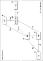
- Fig. 1 is a block diagram showing a first configuration example of communication systems according to an exemplary embodiment of the present invention.
- Fig. 2 is a block diagram showing a second configuration example of the communication systems according to the exemplary embodiment.
- Fig. 3 is a block diagram showing a third configuration example of the communication systems according to the exemplary embodiment.
- Fig. 4 is a block diagram showing examples of connections established between a first node and a base station according to the exemplary embodiment.
- Fig. 5 is a block diagram showing an example of protocol stacks used for the communication systems according to the exemplary embodiment.
- Fig. 6 is a block diagram showing another example of the protocol stacks used for the communication systems according to the exemplary embodiment.
- Fig. 1 is a block diagram showing a first configuration example of communication systems according to an exemplary embodiment of the present invention.
- Fig. 2 is a block diagram showing a second configuration example of the communication systems according to the exemplary embodiment.
- Fig. 3 is a block diagram showing a third
- FIG. 7 is a sequence diagram showing a first example of operations in the communication systems according to the exemplary embodiment.
- Fig. 8 is a sequence diagram showing a second example of the operations in the communication systems according to the exemplary embodiment.
- Fig. 9 is a sequence diagram showing a third example of the operations in the communication systems according to the exemplary embodiment.
- Fig. 10 is a sequence diagram showing a fourth example of the operations in the communication systems according to the exemplary embodiment.
- Fig. 11 is a block diagram showing a configuration example of the first node according to the exemplary embodiment.
- Fig. 12 is a block diagram showing a configuration example of a second node according to the exemplary embodiment.
- Fig. 13 is a block diagram showing a configuration example of a third node according to the exemplary embodiment.
- Fig. 14 is a block diagram showing a configuration example of the base station according to the exemplary embodiment.
- Fig. 15 is a block diagram showing a configuration example of a UE according to the exemplary embodiment.
- Fig. 16 is a block diagram showing a protocol stack between a UE and an MTC-IWF, which will be proposed to 3GPP based on the present invention.
- Fig. 17 is a block diagram showing a packet format which will be proposed to 3GPP based on the present invention.
- This exemplary embodiment considers a UE subscribing to MTC (M2M (Machine-to-Machine)) service, but the present invention is not limited to MTC (M2M) type of application.
- MTC Machine-to-Machine
- New interface T6 This exemplary embodiment proposes a direct interface between an MTC-IWF and an eNB (evolved Node B), named T6.
- This interface is for secure and efficient MTC communication and it supports both CP (Control Plane) and UP (User Plane).
- idea is to use the MTC-IWF as the end point in a mobile network for interconnection with a service provider, and can achieve the following advantageous effects (A) to (G), for example.
- A Offload MME burden caused by the large number of devices communication in case of T5 triggering and small data delivery.
- B Offload MME burden caused by the processing for NAS security in case of T5 triggering and small data delivery.
- MTC-IWF as center point of MTC communication means that UE can also connect over WiFi or any other network element which has interface with MTC-IWF, without any modification.
- MTC-IWF can take care of all issues related to MTC being discussed in 3GPP.
- the MTC-IWF can find the serving eNB indirectly by obtaining the serving eNB information from MME via HSS, or directly from MME.
- MTC trigger and small data are delivered over the T6 interface.
- MTC-IWF and UE establish a security association, and the trigger and small data are protected with keys shared between UE and MTC-IWF.
- MTC-IWF can send the integrity session key it shares with UE to eNB, and thus eNB can perform authorization at an early stage to prevent DoS attack from UEs to network.
- Figs. 1 to 3 show the architecture with new interface T6.
- Fig. 1 shows a configuration example of a communication system for non-roaming case.
- this communication system includes one or more UEs 10, one or more eNB 20, a core network, and an SCS 60.
- the core network includes, as its network nodes, an MME 30, an HSS 40, and an MTC-IFW 50. Note that although the illustration is omitted, the core network also includes, as other network nodes, an SGSN (Serving GPRS (General Packet Radio Service) Support Node), an MSC (Mobile Switching Centre) and the like.
- the SGSN and the MSC function as with the MME 30.
- the UE 10 attaches to the MME 30 through the eNB 20, thereby communicating with the SCS 60 through the core network.
- Messages between the UE 10 and the eNB 20 can be carried on AS (Access Stratum) security.
- Messages between the UE 10 and the MME 30 can be carried on NAS security.
- the UE 10 is a UE equipped for MTC, which will be sometimes referred to as "MTC UE" or "MTC device" in the following description.
- the eNB 20 forms a RAN (Radio Access Network), thereby connecting the UE 10 to the core network.
- RAN Radio Access Network
- messages between the eNB 20 and the MTC-IWF 50 can be carried over the interface T6.
- Messages between the eNB 20 and the MME 30 can be carried over an interface S1.
- the MME 30 manages mobility of the UE 10. Messages between the MME 30 and the HSS 40 are carried over an interface S6a. Messages between the MME 30 and the MTC-IWF 50 can be carried over the interface T5.
- the HSS 40 manages subscription information on the UE 10. Messages between the HSS 40 and the MTC-IWF 50 are carried over an interface S6m.
- the MTC-IWF 50 serves as an entering point to the core network for the SCS 60. Messages between the MTC-IWF 50 and the SCS 60 are carried over an interface Tsp. Upon transmitting traffic between the UE 10 and the SCS 60, the MTC-IWF uses the interface T6.
- the SCS 60 connects to the core network to communicate with the UE 10.
- the UE 10 can host one or multiple MTC Applications.
- the corresponding MTC Applications in the external network are hosted on the SCS 60.
- an H-MTC-IWF (Home MTC-IWF) 50H connects to the eNB 20 via an interface T6'.
- the H-MTC-IWF 50H connects to a V-MTC-IWF 50V via an interface Tiw.
- the V-MTC-IWF 50V connects to the eNB 20 via the interface T6, and connects to the MME 30 via the interface T5.
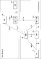
- Fig. 4 shows message flow in case of non-roaming.
- the end-points in 3GPP network for small data and device trigger are UE and MTC-IWF.
- the SDDTE (Small Data and Device Triggering Enhancements) protocol is carried hop-by-hop.
- the eNB 20 and the MME 30 verify whether there is a higher layer protocol (i.e. SDDTE) carrying SD incase the message is carrying SD, they only forward the message but do not perform any process for NAS and AS security.
- SDDTE Small Data and Device Triggering Enhancements
- Fig. 5 shows the proposed protocol stack with using the direct interface.
- Fig. 6 shows the proposed protocol stack with using the virtual interface.
- the protocol SDDTE spans between the UE 10 and the MTC-IWF 50, and can be transparent to the MME/SGSN 30.
- the interface T6 is a direct interface between the eNB 20 and the MTC-IWF 50, the small data and device trigger are transmitted over it directly, and over LTE-Uu between the eNB 20 and the UE 10.
- the small data and derive trigger are transmitted hop-by-hop over T5, S1-MME and LTE-Uu.
- the eNB 20 and the MME 30 verify there is an upper protocol (SDDTE) carrying SD, it only forwards the messages between the MTC-IWF 50 and the eNB 20.
- SDDTE upper protocol
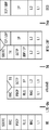
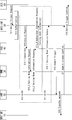
- Fig. 7 shows the trigger delivery flow.
- Steps S15 and S17 are new messages using the T6 interface.
- messages shown at steps S13 and S14 are also modified from the existing messages defined in 3GPP.
- the SCS 60 sends a Device Trigger Request to the MTC-IWF 50 (step S11).
- the MTC-IWF 50 performs authorization (step S12).
- the MTC-IWF 50 does not have subscriber and serving node information, for example, when the MTC-IWF 50 receives request to the UE 10 for the first time, the MTC-IWF 50 will request the HSS 40 for them (step S13).
- the MTC-IWF 50 requests to the HSS 40 of the target device subscriber information (step S13_1).
- the HSS 40 sends a Serving Node Information Request to the MME 30 (step S13_2).
- the MME 30 can be the last MME that the UE 10 attached to.
- the MME 30 responds with a Serving Node Information Response (step S13_3).
- the MME 30 provides the current eNB information to the HSS 40.
- the HSS 40 sends a Subscriber Information Response with serving node information to the MTC-IWF 50 (step S13_4).
- the MME 30 sends a Serving Node Information Update message to the MTC-IWF 50 each time the serving eNB is changed (step S14_1).
- the proposed solution is therefore most effective for low mobility MTC UEs.
- the MTC-IWF 50 submits the Trigger to the current serving eNB 20 over the interface T6 (step S15).
- the eNB 20 pages the UE 10 locally without MME involvement and transfers the message to the UE 10 (step S16).
- the UE 10 may also respond with Ack (Acknowledgement) message.
- the eNB 20 sends a Submit Trigger Confirm message to the MTC-IWF 50 over the interface T6 (step S17).
- the MTC-IWF 50 sends the Device Trigger confirm message to the SCS 60 (step S18).
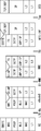
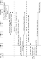
- Fig. 8 shows the MT (Mobile Terminated) Small data transmission flow.
- the MTC-IWF 50 triggers the MME 30 to use normal Paging procedure with indication of small data to inform there will be a small data.
- the MTC-IWF 50 receives a response of Paging, the MTC-IWF 50 sends the small data over interface T6. Steps S24, S28, S29 and S33 are new messages.
- the SCS 60 sends a Small Data submission Request to the MTC-IWF 50 (step S21).
- the MTC-IWF 50 performs authorization on the SCS 60 and the UE 10 (step S22). Upon a successful authorization, the MTC-IWF 50 retrieves the serving node information, from the HSS 40 or directly from the MME 30. Alternatively, the MME 30 sends the Serving Node Information Update to the MTC-IWF 50 each time the serving eNB is changed (step S23).
- the MTC-IWF 50 submits the small data directly to the eNB 20 at step S29, and skips the following steps S24 to S28 in between.
- the eNB 20 performs a local paging of the MTC UE 10 without involving the MME 30 before forwarding the small data to the UE 10. This would be more effective especially for low mobility MTC UEs.
- the MME 30 sends the Request Paging message to the eNB 20 (step S25).
- the eNB 20 sends the Paging message to the UE 10 (step S26).
- the UE 10 responds to the Paging from the MME 30 with a Service Request message (step S27).
- the MME 30 sends a Response Paging message with UE ID and the eNB address to the MTC-IWF 50 (step S28). This will indicate the MTC-IWF 50 that the MME 30 has paged the UE 10 and received a response, and thus the MTC-IWF 50 can send the small data directly to the eNB 20.
- the eNB 20 forwards the Small Data to the UE 10 (step S30).
- the UE 10 performs integrity check with the key it shares with the MTC-IWF 50 (step S31).
- the UE 10 sends a confirm of receiving the Small Data if the integrity check was successful at previous step S31 (step S32).
- the eNB 20 forwards the submit small data confirm to the MTC-IWF 50 (step S33).
- the MTC-IWF 50 forwards the submit confirm to the SCS 60 (step S34).
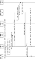
- Fig. 9 shows the MO (Mobile Originated) Small data transmission flow.
- Step S44, S48 and S50 are new messages using the interface T6.
- a message shown at step S43 is also new.
- the UE 10 sends a Small Data submission Request with integrity and/or confidentiality protection by the key it shares with the MTC-IWF 50 (step S41).
- the request message is sent on SRB0 (Signalling Radio Bearer 0, as defined in 3GPP 36.331), and it contains SCS ID. There is no need to establish RRC connection between the UE 10 and the eNB 20, so that RRC signaling can be reduced.
- SRB0 Signaling Radio Bearer 0, as defined in 3GPP 36.331
- the eNB 20 retrieves routing information from the MME 30, of which MTC-IWF to communicate with (step S43).
- the eNB 20 forwards the small data to the MTC-IWF 50 (step S44).
- the MTC-IWF 50 performs integrity check, with the key it shares with the UE 10 (step S45). If the integrity check is successful, the MTC-IWF 50 delivers small data to the SCS 60 (step S46).
- the SCS 60 responds Small data confirm to the MTC-IWF 50 (step S47).
- the MTC-IWF 50 forwards the Small data confirm to the eNB 20 (step S48).
- the eNB 20 forwards the Small data confirm to the UE 10 (step S49).
- Step S6 If the integrity check fails at above Step S6, the MTC-IWF 50 sends Small Data Reject to the UE 10 (step S50).
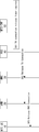
- T6 Connection Release If the T6 connection has not been active for a given time then it can be released. The T6 connection release procedure is given in Fig. 10.
- a T6 connection release timer expires at the MTC-IWF 50 (step S61).
- the MTC-IWF 50 indicates the eNB 20 to release the T6 Connection (step S62).
- the eNB 20 removes related information for small data and device trigger. Note that this procedure is also applied to the MME 30 when virtual interface T6 is in use.
- the eNB 20 sends Release RRC Connection to the UE 10, if there is a RRC Connection (step S63).
- Changes to current network element 4.1. Changes to eNB: Need to support new interface T6, new protocol, need to interact with MME for MTC-IWF information, verify if the message carries SD, (optionally) perform authorization on UE.
- HSS HSS will query MME about serving eNB information and provide it to MTC-IWF at initial phase.
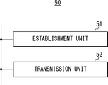
- MTC-IWF 50 configuration examples of the MTC-IWF 50, the MME 30, the HSS 40, the eNB 20, and the UE 10 will be described with reference to Figs. 11 to 15. Note that in the following explanation, there will be described only elements which specific to this exemplary embodiment. However, it will be understood that the MTC-IWF 50, the MME 30, the HSS 40, the eNB 20, and the UE 10 also include elements for functioning as typical MTC-IWF, MME, HSS, eNB and UE, respectively.
- the MTC-IWF 50 includes an establishment unit 51 and a transmission unit 52.
- the establishment unit 51 establishes the above-mentioned T6 connection to the eNB 20.
- the establishment unit 51 acquires the Serving Node Information from the MME 30 or the HSS 40.
- the transmission unit 52 transmits the above-mentioned MTC device trigger message and Small Data Transmission message between the UE 10 and the SCS 60.
- these units 51 and 52 are mutually connected with each other through a bus or the like.
- These units 51 and 52 can be configured by, for example, transceivers which respectively conduct communication with the eNB 20, the MME 30, the HSS 40 and the SCS 60, and a controller such as a CPU (Central Processing Unit) which controls these transceivers.
- a CPU Central Processing Unit
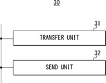
- the MME 30 includes a transfer unit 31 and a send unit 32.
- the transfer unit 31 transparently transfers the MTC device trigger message and the Small Data Transmission message between the eNB 20 and the MTC-IWF 50.
- the send unit 32 sends the Serving Node Information directly to the MTC-IWF 50, or through the HSS 40.
- these units 31 and 32 are mutually connected with each other through a bus or the like.
- These units 31 and 32 can be configured by, for example, transceivers which respectively conduct communication with the eNB 20, the HSS 40 and the MCT-IWF 50, and a controller such as a CPU which controls these transceivers.
- the HSS 40 includes a request unit 41 and a send unit 42.
- the request unit 41 requests the Serving Node Information from the MME 30.
- the send unit 42 sends the Serving Node Information to the MTC-IWF 50.
- these units 41 and 42 are mutually connected with each other through a bus or the like.
- These units 41 and 42 can be configured by, for example, transceivers which respectively conduct communication with the MME 30 and the MCT-IWF 50, and a controller such as a CPU which controls these transceivers.
- the eNB 20 includes a transceiving unit 21.
- the transceiving unit 21 transceives the MTC device trigger message and the Small Data Transmission message between the eNB 20 and the MTC-IWF 50. Further, the transceiving unit 21 retrieves the routing information from the MME 30. Furthermore, the transceiving unit 21 receives, on the SRB0, the MO Small Data Transmission message from the UE 10.
- This unit 21 can be configured by, for example, transceivers which respectively conduct communication with the UE 10, the MME 30 and the MCT-IWF 50, and a controller such as a CPU which controls these transceivers.
- the UE 10 includes a send unit 11.
- the send unit 11 sends, on the SRB0, the MO Small Data Transmission message to the eNB 20.
- This unit 11 can be configured by, for example, a transceiver which conducts communication with the eNB 20, and a controller such as a CPU which controls this transceiver.
- MTC-IWF Small Data
- MME when MME receives a NAS message carrying Small Data (SD), it does the following, 1) Check if the NAS message carries SD. 2) If YES, forward the SD to MTC-IWF and act on the NAS message as defined in TS 33.401. If NO, act on the NAS message as defined in TS 33.401.
- SD Small Data
- the MME will have to (1) check whether a NAS message carries SD and (2) forward the SD to the MTC-IWF.
- the MME has to carry the burden of integrity and confidentiality protection as well.
- MME Mobility Management Entity
- Fig. 16 depicts the protocol stack for MTC-IWF based solution in more detail.
- the protocol between UE and MTC-IWF can be based on PDCP (Packet Data Convergence Protocol).
- PDCP Packet Data Convergence Protocol
- MTC-IWF can be configured with the same algorithms that UE has.
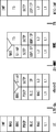
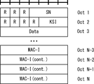
- Fig. 17 shows the packet format for SD that is based on the format defined in [TS 36.323].
- SN Sequence Number
- KSI Key Set Identifier
- MAC-I Message Authentication Code for Integrity
- the solution consists of 1) Authentication and Key Agreement (AKA). During this procedure, HSS derives a master key K_iwf and sends it to MTC-IWF. 2) keys negotiation and establishment using a new Security Mode Command (SMC) procedure carried between UE and MTC-IWF - this new procedure can ride on NAS SMC. As a result of this procedure, UE and MTC-IWF share the same K_iwf and subkeys for confidentiality and integrity protection. 3) SD (both mobile originated, MO, and mobile terminated, MT) and trigger transmission: the transmission can ride on packets that do not need NAS security as per current specification, with recognition of such data is being carried, NAS security can be omitted. In the following section we propose the detailed solution.
- AKA Authentication and Key Agreement
- SMC Security Mode Command
- the IWF protocol is between NAS and application layer protocol for MTC, it spans between UE and MTC-IWF and can be transparent to MME/SGSN/MSC.
- the T5-AP defined in clause 5.1.1.3.3 TR 23.887 [26] can be used.
- Fig. 16 illustrates the protocol stack.
- the protocol between UE and MTC-IWF can be based on PDCP.
- PDCP provides both ciphering, deciphering, integrity protection and integrity verification (as defined in [TS 36.323]) which can be re-used.
- MTC-IWF can be configured with the same algorithms that UE has.
- Fig. 17 shows the packet format for SD that is based on the format defined in [TS 36.323].
- SN can be used to prevent replay attack.
- KSI is a key identifier of subkeys for UE and MTC-IWF to determine the key to be used for small data transmission protection.
- MAC-I is computed by the integrity subkey.
- HSS requests serving eNB information from MME and sends it to MTC-IWF in Subscriber Information Response.
- MME informs the eNB change by sending Serving Node Information Update to MTC-IWF at the change happens.
- eNB retrieves serving MTC-IWF information from MME for MO small data transmission.
- eNB pages the MTC UE locally without MME involvement before submitting the small data, especially beneficial for low mobility MTC UEs.
- UE sends MO small data or MT small data confirm on SRB0, thus there is no need to have RRC Connection Establishment so as to reduce RRC signaling.
- MTC-IWF sends the integrity session key, which it shares with UE, to eNB.
- a node that serves as an entering point to a core network for a service provider comprising: establishment means for establishing a connection to a base station; and transmission means for transmitting, by use of the connection, traffic between the service provider and a UE (User Equipment) that attaches to the core network through the base station, wherein the establishment means is configured to establish as the connection: a first connection for directly transceiving messages between the node and the base station; or a second connection for transparently transceiving the messages through a different node that is placed within the core network and has established a different secure connection to the base station.
- the establishment means is configured to establish as the connection: a first connection for directly transceiving messages between the node and the base station; or a second connection for transparently transceiving the messages through a different node that is placed within the core network and has established a different secure connection to the base station.
- the node according to Supplementary note 10 wherein the different node comprises an MME (Mobility Management Entity), wherein the establishment means is configured to acquire the information from the MME through an HSS (Home Subscriber Server).
- MME Mobility Management Entity
- HSS Home Subscriber Server
- a node that manages mobility of a UE attaching to a core network through a base station comprising: transfer means for transparently transferring messages between the base station and a different node, the different node serving as an entering point to the core network for a service provider and transmitting traffic between the service provider and the UE.
- the node according to Supplementary note 14 further comprising: send means for sending information on the base station to the different node.
- a node that manages subscription information on a UE attaching to a core network through a base station comprising: request means for requesting information on the base station from a first node that manages mobility of the UE; and send means for sending the information to a second node that serves as an entering point to the core network for a service provider and that transmits traffic between the service provider and the UE.
- a base station comprising: transceiving means for transceiving messages between the base station and a node through a first connection or a second connection to the node, the node serving as an entering point to a core network for a service provider and transmitting traffic between the service provider and a UE that attaches to the core network through the base station, the first connection being for directly transceiving the messages, the second connection being for transparently transceiving the messages through a different node that is placed within the core network and has established a different secure connection to the base station.
- a UE that attaches to a core network through a base station and that communicates with a service provider, the UE comprising: send means for sending, on a SRB0, to the base station a message to be transmitted to the service provider through the core network.
- a communication system comprising: a base station that connects a UE to a core network; and a node that serves as an entering point to the core network for a service provider and that transmits traffic between the service provider and the UE, wherein the node establishes as a connection to the base station: a first connection for directly transceiving messages between the node and the base station; or a second connection for transparently transceiving the messages through a different node that is placed within the core network and has established a different secure connection to the base station.
- a method of controlling operation in a node that serves as an entering point to a core network for a service provider comprising: establishing a connection to a base station; and transmitting, by use of the connection, traffic between the service provider and a UE that attaches to the core network through the base station, wherein as the connection, one of following connections is established: a first connection for directly transceiving messages between the node and the base station; or a second connection for transparently transceiving the messages through a different node that is placed within the core network and has established a different secure connection to the base station.
- a method of controlling operations in a node that manages mobility of a UE attaching to a core network through a base station comprising: transparently transferring messages between the base station and a different node, the different node serving as an entering point to the core network for a service provider and transmitting traffic between the service provider and the UE.
- a method of controlling operations in a node that manages subscription information on a UE attaching to a core network through a base station comprising: requesting information on the base station from a first node that manages mobility of the UE; and sending the information to a second node that serves as an entering point to the core network for a service provider and that transmits traffic between the service provider and the UE.
- a method of controlling operations in a base station comprising: transceiving messages between the base station and a node through a first connection or a second connection to the node, the node serving as an entering point to a core network for a service provider and transmitting traffic between the service provider and a UE that attaches to the core network through the base station, the first connection being for directly transceiving the messages, the second connection being for transceiving the messages transparently through a different node that is placed within the core network and has established a different secure connection to the base station.
- a method of controlling operations in a UE that attaches to a core network through a base station and that communicates with a service provider comprising: sending, on a radio bearer shared with one or more different UEs, to the base station a message to be transmitted to the service provider through the core network.
Priority Applications (9)
| Application Number | Priority Date | Filing Date | Title |
|---|---|---|---|
| CN201480060035.2A CN105684469A (zh) | 2013-10-31 | 2014-10-21 | Mtc所用的设备、系统和方法 |
| US15/032,847 US9848334B2 (en) | 2013-10-31 | 2014-10-21 | Apparatus, system and method for MTC |
| JP2016527473A JP2016541175A (ja) | 2013-10-31 | 2014-10-21 | Mtcのための装置、システム、及び方法 |
| EP14795678.3A EP3063971A1 (en) | 2013-10-31 | 2014-10-21 | Apparatus, system and method for mtc |
| US15/808,527 US10306475B2 (en) | 2013-10-31 | 2017-11-09 | Apparatus, system and method for mobile communication |
| US15/808,515 US10299134B2 (en) | 2013-10-31 | 2017-11-09 | Apparatus, system and method for mobile communication |
| US16/287,806 US10681553B2 (en) | 2013-10-31 | 2019-02-27 | Apparatus, system, and method for mobile communication |
| US16/860,855 US20200260286A1 (en) | 2013-10-31 | 2020-04-28 | Apparatus, system and method for mobile communication |
| US17/067,311 US11601790B2 (en) | 2013-10-31 | 2020-10-09 | Apparatus, system and method for mobile communication |
Applications Claiming Priority (2)
| Application Number | Priority Date | Filing Date | Title |
|---|---|---|---|
| JP2013-226680 | 2013-10-31 | ||
| JP2013226680 | 2013-10-31 |
Related Child Applications (3)
| Application Number | Title | Priority Date | Filing Date |
|---|---|---|---|
| US15/032,847 A-371-Of-International US9848334B2 (en) | 2013-10-31 | 2014-10-21 | Apparatus, system and method for MTC |
| US15/808,515 Continuation US10299134B2 (en) | 2013-10-31 | 2017-11-09 | Apparatus, system and method for mobile communication |
| US15/808,527 Continuation US10306475B2 (en) | 2013-10-31 | 2017-11-09 | Apparatus, system and method for mobile communication |
Publications (1)
| Publication Number | Publication Date |
|---|---|
| WO2015064056A1 true WO2015064056A1 (en) | 2015-05-07 |
Family
ID=51868275
Family Applications (1)
| Application Number | Title | Priority Date | Filing Date |
|---|---|---|---|
| PCT/JP2014/005332 WO2015064056A1 (en) | 2013-10-31 | 2014-10-21 | Apparatus, system and method for mtc |
Country Status (5)
| Country | Link |
|---|---|
| US (6) | US9848334B2 (ja) |
| EP (2) | EP3300403A1 (ja) |
| JP (1) | JP2016541175A (ja) |
| CN (2) | CN105684469A (ja) |
| WO (1) | WO2015064056A1 (ja) |
Cited By (2)
| Publication number | Priority date | Publication date | Assignee | Title |
|---|---|---|---|---|
| WO2019074600A1 (en) * | 2017-10-13 | 2019-04-18 | Qualcomm Incorporated | TRANSFER OF CONFIGURATION DATA PROTECTED FROM A DOMESTIC MOBILE NETWORK |
| CN113225701A (zh) * | 2015-11-10 | 2021-08-06 | 夏普株式会社 | Ue、控制装置以及通信控制方法 |
Citations (1)
| Publication number | Priority date | Publication date | Assignee | Title |
|---|---|---|---|---|
| US20130273855A1 (en) * | 2012-04-16 | 2013-10-17 | Qualcomm Incorporated | Systems, methods, and apparatus for machine to machine device triggering |
Family Cites Families (51)
| Publication number | Priority date | Publication date | Assignee | Title |
|---|---|---|---|---|
| JP2001144811A (ja) | 1999-11-17 | 2001-05-25 | Sharp Corp | モバイルipにおける通信制御方式 |
| CN1177436C (zh) * | 2002-02-09 | 2004-11-24 | 华为技术有限公司 | 移动网络中多播用户的管理方法 |
| KR100946697B1 (ko) * | 2006-11-13 | 2010-03-12 | 한국전자통신연구원 | 소형 패킷 데이터를 고속으로 암호화할 수 있는 IPsec암호화 장치 및 방법 |
| KR101370909B1 (ko) * | 2007-10-01 | 2014-03-19 | 엘지전자 주식회사 | 핸드오버시 신속한 상향 데이터 전송방법 |
| CN101610201A (zh) | 2008-06-20 | 2009-12-23 | 大唐移动通信设备有限公司 | 实现pdn连接释放的方法、装置和系统 |
| US9923735B2 (en) * | 2009-05-05 | 2018-03-20 | Nokia Technologies Oy | Systems, methods, and apparatuses for handling a legacy circuit switched communication |
| CN102056204B (zh) * | 2009-10-30 | 2013-11-06 | 中兴通讯股份有限公司 | 一种实现用户终端注销的方法和系统 |
| CN102118789B (zh) * | 2009-12-31 | 2013-02-27 | 华为技术有限公司 | 业务卸载方法、业务卸载功能实体和业务卸载系统 |
| KR101641542B1 (ko) * | 2010-01-15 | 2016-07-22 | 삼성전자주식회사 | 메시지 전송 방법 및 시스템 |
| KR101824987B1 (ko) * | 2010-02-11 | 2018-02-02 | 엘지전자 주식회사 | 이동통신 시스템에서의 다운링크 mtc 데이터 전송 방법 |
| CN102754485A (zh) * | 2010-02-12 | 2012-10-24 | 交互数字专利控股公司 | 机器对机器通信中的接入控制和拥塞控制 |
| WO2011112051A2 (ko) * | 2010-03-11 | 2011-09-15 | 엘지전자 주식회사 | 무선 통신 시스템에서 mtc를 위한 방법 및 장치 |
| KR101766474B1 (ko) * | 2010-03-23 | 2017-08-23 | 인터디지탈 패튼 홀딩스, 인크 | 기계형 통신을 위한 효율적 시그널링을 위한 장치 및 그에 관한 방법 |
| US8724548B2 (en) * | 2010-04-22 | 2014-05-13 | Qualcomm Incorporated | Counter check procedure for packet data transmission |
| CN102238520B (zh) * | 2010-04-26 | 2014-12-31 | 中兴通讯股份有限公司 | 一种小数据包传输的方法和系统 |
| KR101592630B1 (ko) | 2010-06-18 | 2016-02-05 | 후지쯔 가부시끼가이샤 | 무선 통신 방법, 무선 통신 장치 및 무선 통신 시스템 |
| CN102594555B (zh) * | 2011-01-17 | 2015-04-29 | 华为技术有限公司 | 数据的安全保护方法、网络侧实体和通信终端 |
| EP2509345A1 (en) * | 2011-04-05 | 2012-10-10 | Panasonic Corporation | Improved small data transmissions for machine-type-communication (MTC) devices |
| WO2012147270A1 (en) * | 2011-04-28 | 2012-11-01 | Panasonic Corporation | Communication system, mobile terminal, router, and mobility management entity |
| CN103534960B (zh) * | 2011-05-11 | 2017-08-08 | Lg电子株式会社 | 用于无线通信系统中的mtc的方法和设备 |
| TWI459777B (zh) * | 2011-07-11 | 2014-11-01 | Mediatek Inc | 加強型傳呼的方法及其機器類型通訊裝置 |
| GB2493349A (en) * | 2011-07-29 | 2013-02-06 | Intellectual Ventures Holding 81 Llc | Mobile communications network with simplified handover |
| US8938233B2 (en) * | 2011-08-16 | 2015-01-20 | Mediatek Inc. | Enhanced access control in LTE advanced systems |
| CN102300331B (zh) * | 2011-08-19 | 2013-11-27 | 电信科学技术研究院 | 数据传输方法和设备 |
| CN102333293B (zh) * | 2011-09-21 | 2014-07-09 | 电信科学技术研究院 | 一种小数据的传输方法和设备 |
| US9973877B2 (en) * | 2011-09-23 | 2018-05-15 | Htc Corporation | Method of handling small data transmission |
| CN102340754B (zh) * | 2011-09-23 | 2014-07-23 | 电信科学技术研究院 | 数据发送和接收方法及设备 |
| WO2013052163A1 (en) * | 2011-10-03 | 2013-04-11 | Intel Corporation | Device to device (d2d) communication mechanisms |
| RU2014122557A (ru) * | 2011-11-04 | 2015-12-10 | Квэлкомм Инкорпорейтед | Способы и устройства для обновления функциональных возможностей ue в e-utran |
| CN102340826B (zh) * | 2011-11-17 | 2016-05-25 | 电信科学技术研究院 | 一种数据传输的方法和设备 |
| US20130137469A1 (en) * | 2011-11-30 | 2013-05-30 | Intel Mobile Communications GmbH | Method for transmitting an opportunistic network related message |
| CN103220642B (zh) * | 2012-01-19 | 2016-03-09 | 华为技术有限公司 | 一种短消息的安全处理方法和装置 |
| US8953478B2 (en) * | 2012-01-27 | 2015-02-10 | Intel Corporation | Evolved node B and method for coherent coordinated multipoint transmission with per CSI-RS feedback |
| KR102058954B1 (ko) * | 2012-02-06 | 2019-12-26 | 삼성전자 주식회사 | 무선 통신 시스템에서 small data를 효율적으로 전송하는 방법 및 장치 |
| US9143984B2 (en) * | 2012-04-13 | 2015-09-22 | Intel Corporation | Mapping of enhanced physical downlink control channels in a wireless communication network |
| CN103517409B (zh) * | 2012-06-25 | 2018-04-27 | 华为终端有限公司 | 信息传输方法、系统及设备 |
| US9100160B2 (en) * | 2012-08-03 | 2015-08-04 | Intel Corporation | Apparatus and method for small data transmission in 3GPP-LTE systems |
| CN202872810U (zh) * | 2012-08-15 | 2013-04-10 | 泰克威科技(深圳)有限公司 | 基于小型网络存储服务器上主动式数据安全备份系统 |
| CN104704790A (zh) * | 2012-09-13 | 2015-06-10 | 日本电气株式会社 | 机器型通信系统中的密钥管理 |
| US8923880B2 (en) * | 2012-09-28 | 2014-12-30 | Intel Corporation | Selective joinder of user equipment with wireless cell |
| CN103716753B (zh) * | 2012-09-29 | 2018-12-25 | 中兴通讯股份有限公司 | 一种小数据发送方法、系统及用户设备 |
| EP2904869B1 (en) * | 2012-10-08 | 2021-01-13 | Nokia Solutions and Networks Oy | Methods, devices, and computer program products for keeping devices attached without a default bearer |
| EP2725852B1 (en) * | 2012-10-29 | 2016-07-20 | Alcatel Lucent | Optimization of network signaling load and/or of user equipment power consumption in a packet mobile system |
| WO2014148746A1 (ko) * | 2013-03-21 | 2014-09-25 | 주식회사 케이티 | 소량 데이터 전송을 위한 방법 및 그 장치 |
| CN104247499B (zh) * | 2013-03-26 | 2018-09-21 | 华为技术有限公司 | 数据包传输方法、系统及终端设备和网络设备 |
| US9160515B2 (en) * | 2013-04-04 | 2015-10-13 | Intel IP Corporation | User equipment and methods for handover enhancement using scaled time-to-trigger and time-of-stay |
| CN104247328B (zh) * | 2013-04-17 | 2017-06-06 | 华为技术有限公司 | 数据传输方法和装置 |
| CN109219005B (zh) * | 2013-04-23 | 2020-12-22 | 华为技术有限公司 | 一种数据包传输的方法和设备 |
| CN104144524B (zh) * | 2013-05-08 | 2018-05-11 | 电信科学技术研究院 | 一种小数据传输方法和演进基站及用户终端 |
| CN104349311A (zh) * | 2013-08-02 | 2015-02-11 | 中兴通讯股份有限公司 | 一种用于机器类通信小数据传输的密钥建立方法和系统 |
| US9692567B1 (en) * | 2013-09-04 | 2017-06-27 | Cisco Technology, Inc. | Targeted service request for small data communication in a network environment |
-
2014
- 2014-10-21 JP JP2016527473A patent/JP2016541175A/ja active Pending
- 2014-10-21 EP EP17199672.1A patent/EP3300403A1/en not_active Ceased
- 2014-10-21 CN CN201480060035.2A patent/CN105684469A/zh active Pending
- 2014-10-21 EP EP14795678.3A patent/EP3063971A1/en not_active Withdrawn
- 2014-10-21 WO PCT/JP2014/005332 patent/WO2015064056A1/en active Application Filing
- 2014-10-21 US US15/032,847 patent/US9848334B2/en active Active
- 2014-10-21 CN CN201910313315.4A patent/CN110087219A/zh active Pending
-
2017
- 2017-11-09 US US15/808,527 patent/US10306475B2/en active Active
- 2017-11-09 US US15/808,515 patent/US10299134B2/en active Active
-
2019
- 2019-02-27 US US16/287,806 patent/US10681553B2/en active Active
-
2020
- 2020-04-28 US US16/860,855 patent/US20200260286A1/en not_active Abandoned
- 2020-10-09 US US17/067,311 patent/US11601790B2/en active Active
Patent Citations (1)
| Publication number | Priority date | Publication date | Assignee | Title |
|---|---|---|---|---|
| US20130273855A1 (en) * | 2012-04-16 | 2013-10-17 | Qualcomm Incorporated | Systems, methods, and apparatus for machine to machine device triggering |
Non-Patent Citations (5)
Cited By (5)
| Publication number | Priority date | Publication date | Assignee | Title |
|---|---|---|---|---|
| CN113225701A (zh) * | 2015-11-10 | 2021-08-06 | 夏普株式会社 | Ue、控制装置以及通信控制方法 |
| CN113225701B (zh) * | 2015-11-10 | 2022-07-19 | 夏普株式会社 | Ue、控制装置以及通信控制方法 |
| WO2019074600A1 (en) * | 2017-10-13 | 2019-04-18 | Qualcomm Incorporated | TRANSFER OF CONFIGURATION DATA PROTECTED FROM A DOMESTIC MOBILE NETWORK |
| CN111201805A (zh) * | 2017-10-13 | 2020-05-26 | 高通股份有限公司 | 受保护配置数据从本地移动网络的传送 |
| US11172360B2 (en) | 2017-10-13 | 2021-11-09 | Qualcomm Incorporated | Transfer of security protected configuration data from HPLMN |
Also Published As
| Publication number | Publication date |
|---|---|
| US10681553B2 (en) | 2020-06-09 |
| US10299134B2 (en) | 2019-05-21 |
| US20190200231A1 (en) | 2019-06-27 |
| CN105684469A (zh) | 2016-06-15 |
| US20210029523A1 (en) | 2021-01-28 |
| US11601790B2 (en) | 2023-03-07 |
| US10306475B2 (en) | 2019-05-28 |
| US9848334B2 (en) | 2017-12-19 |
| CN110087219A (zh) | 2019-08-02 |
| US20200260286A1 (en) | 2020-08-13 |
| JP2016541175A (ja) | 2016-12-28 |
| US20180077578A1 (en) | 2018-03-15 |
| US20180070240A1 (en) | 2018-03-08 |
| EP3063971A1 (en) | 2016-09-07 |
| EP3300403A1 (en) | 2018-03-28 |
| US20160269907A1 (en) | 2016-09-15 |
Similar Documents
| Publication | Publication Date | Title |
|---|---|---|
| US10652085B2 (en) | Method for setting configuration of non-IP data delivery (NDID) in wireless communication system and device for same | |
| US10716161B2 (en) | Method for resuming connection in wireless communication system and device for same | |
| US11564121B2 (en) | Load control from control plane CIoT EPS optimization | |
| EP2757825B1 (en) | Method, system and device for transmitting data | |
| KR101706383B1 (ko) | 이동 통신 시스템에서 단문 메시지 서비스 메시지 전달 방법 및 시스템 | |
| JP6138058B2 (ja) | サーバ及び通信端末 | |
| TWI713614B (zh) | 用於使用支援多個連線性和服務上下文的安全模型的無線通訊的方法和裝置 | |
| US8848610B2 (en) | Lightweight data transmission mechanism | |
| US11296976B2 (en) | Optimization of MTC device trigger delivery | |
| JP2016502767A (ja) | Mtcのためのグループ認証及びキー管理 | |
| US20180063135A1 (en) | Method for performing authentication of user equipment for individual services in wireless communication system and apparatus for the same | |
| US11601790B2 (en) | Apparatus, system and method for mobile communication | |
| KR102295847B1 (ko) | 사용자 장치를 제어하는 방법 | |
| US11576232B2 (en) | Method for establishing a connection of a mobile terminal to a mobile radio communication network and communication network device | |
| JP2013239837A (ja) | ネットワークノード及びサーバ | |
| CN118044327A (en) | Communicating early data and non-early data between a user equipment and a core network |
Legal Events
| Date | Code | Title | Description |
|---|---|---|---|
| 121 | Ep: the epo has been informed by wipo that ep was designated in this application |
Ref document number: 14795678 Country of ref document: EP Kind code of ref document: A1 |
|
| REEP | Request for entry into the european phase |
Ref document number: 2014795678 Country of ref document: EP |
|
| WWE | Wipo information: entry into national phase |
Ref document number: 2014795678 Country of ref document: EP |
|
| ENP | Entry into the national phase |
Ref document number: 2016527473 Country of ref document: JP Kind code of ref document: A |
|
| WWE | Wipo information: entry into national phase |
Ref document number: 15032847 Country of ref document: US |
|
| NENP | Non-entry into the national phase |
Ref country code: DE |