WO2015060352A1 - Organic electroluminescent element and electronic device - Google Patents
Organic electroluminescent element and electronic device Download PDFInfo
- Publication number
- WO2015060352A1 WO2015060352A1 PCT/JP2014/078108 JP2014078108W WO2015060352A1 WO 2015060352 A1 WO2015060352 A1 WO 2015060352A1 JP 2014078108 W JP2014078108 W JP 2014078108W WO 2015060352 A1 WO2015060352 A1 WO 2015060352A1
- Authority
- WO
- WIPO (PCT)
- Prior art keywords
- group
- substituted
- unsubstituted
- ring
- carbon atoms
- Prior art date
Links
- FQQLVBIVNYKZDG-UHFFFAOYSA-N N#Cc(cc1)cc(C#N)c1-[n]1c(ccc(-c(cc2)cc(c3cc(-[n]4c5ccccc5c5c4cccc5)ccc33)c2[n]3-c2ccccc2)c2)c2c2c1cccc2 Chemical compound N#Cc(cc1)cc(C#N)c1-[n]1c(ccc(-c(cc2)cc(c3cc(-[n]4c5ccccc5c5c4cccc5)ccc33)c2[n]3-c2ccccc2)c2)c2c2c1cccc2 FQQLVBIVNYKZDG-UHFFFAOYSA-N 0.000 description 1
- MRHHGPQHLFKHFL-UHFFFAOYSA-N N#Cc(cc1)cc(C#N)c1-[n]1c(ccc(-c(cc2)cc(c3cc(-c4ccccc4)ccc33)c2[n]3-c2ccccc2)c2)c2c2cc(-c3ccccc3)ccc12 Chemical compound N#Cc(cc1)cc(C#N)c1-[n]1c(ccc(-c(cc2)cc(c3cc(-c4ccccc4)ccc33)c2[n]3-c2ccccc2)c2)c2c2cc(-c3ccccc3)ccc12 MRHHGPQHLFKHFL-UHFFFAOYSA-N 0.000 description 1
- RNOPNNHNZCWWBR-UHFFFAOYSA-N N#Cc(cc1-[n]2c(ccc(-c(cc3c4cc(-c5ccccc5)ccc44)ccc3[n]4-c3ccccc3)c3)c3c3cc(-c4ccccc4)ccc23)ccc1C#N Chemical compound N#Cc(cc1-[n]2c(ccc(-c(cc3c4cc(-c5ccccc5)ccc44)ccc3[n]4-c3ccccc3)c3)c3c3cc(-c4ccccc4)ccc23)ccc1C#N RNOPNNHNZCWWBR-UHFFFAOYSA-N 0.000 description 1
- QAZPFLTYCPZZBT-UHFFFAOYSA-N N#Cc(ccc(-[n]1c(ccc(-c(cc2)cc(c3cc(-[n]4c5ccccc5c5c4cccc5)ccc33)c2[n]3-c2ccccc2)c2)c2c2ccccc12)c1)c1C#N Chemical compound N#Cc(ccc(-[n]1c(ccc(-c(cc2)cc(c3cc(-[n]4c5ccccc5c5c4cccc5)ccc33)c2[n]3-c2ccccc2)c2)c2c2ccccc12)c1)c1C#N QAZPFLTYCPZZBT-UHFFFAOYSA-N 0.000 description 1
- IDPCGDJFMLBYDX-UHFFFAOYSA-N N#Cc(ccc(-[n]1c(ccc(-c(cc2)cc(c3cc(-c4ccccc4)ccc33)c2[n]3-c2ccccc2)c2)c2c2cc(-c3ccccc3)ccc12)c1)c1C#N Chemical compound N#Cc(ccc(-[n]1c(ccc(-c(cc2)cc(c3cc(-c4ccccc4)ccc33)c2[n]3-c2ccccc2)c2)c2c2cc(-c3ccccc3)ccc12)c1)c1C#N IDPCGDJFMLBYDX-UHFFFAOYSA-N 0.000 description 1
- GBTGXWCNWJDXBO-UHFFFAOYSA-N N#Cc(cccc1-[n]2c(ccc(-c(cc3c4c5ccc(-c6ccccc6)c4)ccc3[n]5-c3ccccc3)c3)c3c3cc(-c4ccccc4)ccc23)c1C#N Chemical compound N#Cc(cccc1-[n]2c(ccc(-c(cc3c4c5ccc(-c6ccccc6)c4)ccc3[n]5-c3ccccc3)c3)c3c3cc(-c4ccccc4)ccc23)c1C#N GBTGXWCNWJDXBO-UHFFFAOYSA-N 0.000 description 1
- VDDMDHSPXZXROA-UHFFFAOYSA-N N#Cc1cc(-[n](c(c(c2c3)c4)ccc4-c4ccccc4)c2ccc3-c(cc2c3c4ccc(-c5ccccc5)c3)ccc2[n]4-c2ccccc2)cc(C#N)c1 Chemical compound N#Cc1cc(-[n](c(c(c2c3)c4)ccc4-c4ccccc4)c2ccc3-c(cc2c3c4ccc(-c5ccccc5)c3)ccc2[n]4-c2ccccc2)cc(C#N)c1 VDDMDHSPXZXROA-UHFFFAOYSA-N 0.000 description 1
- AEHJSEGQANUSBM-UHFFFAOYSA-N N#Cc1cc(-[n]2c3cccc(-c(cc4)cc(c5cc(-c6ccccc6)ccc55)c4[n]5-c4ccccc4)c3c3cc(-c4ccccc4)ccc23)cc(C#N)c1 Chemical compound N#Cc1cc(-[n]2c3cccc(-c(cc4)cc(c5cc(-c6ccccc6)ccc55)c4[n]5-c4ccccc4)c3c3cc(-c4ccccc4)ccc23)cc(C#N)c1 AEHJSEGQANUSBM-UHFFFAOYSA-N 0.000 description 1
- KLOGKIWJCYMOCE-UHFFFAOYSA-N N#Cc1cccc(-[n]2c(ccc(-c(cc3)cc(c4cc(-[n]5c6ccccc6c6c5cccc6)ccc44)c3[n]4-c3ccccc3)c3)c3c3ccccc23)c1C#N Chemical compound N#Cc1cccc(-[n]2c(ccc(-c(cc3)cc(c4cc(-[n]5c6ccccc6c6c5cccc6)ccc44)c3[n]4-c3ccccc3)c3)c3c3ccccc23)c1C#N KLOGKIWJCYMOCE-UHFFFAOYSA-N 0.000 description 1
- ZMOBNUNTKRANHQ-UHFFFAOYSA-N N#Cc1cccc(-[n]2c3cccc(-c(cc4c5c6ccc(-c7ccccc7)c5)ccc4[n]6-c4ccccc4)c3c3c2ccc(-c2ccccc2)c3)c1C#N Chemical compound N#Cc1cccc(-[n]2c3cccc(-c(cc4c5c6ccc(-c7ccccc7)c5)ccc4[n]6-c4ccccc4)c3c3c2ccc(-c2ccccc2)c3)c1C#N ZMOBNUNTKRANHQ-UHFFFAOYSA-N 0.000 description 1
- NNPWQGCEPWPHBO-UHFFFAOYSA-N N#Cc1cccc(C#N)c1-[n]1c(ccc(-c(cc2c3cc(-c4ccccc4)ccc33)ccc2[n]3-c2ccccc2)c2)c2c2cc(-c3ccccc3)ccc12 Chemical compound N#Cc1cccc(C#N)c1-[n]1c(ccc(-c(cc2c3cc(-c4ccccc4)ccc33)ccc2[n]3-c2ccccc2)c2)c2c2cc(-c3ccccc3)ccc12 NNPWQGCEPWPHBO-UHFFFAOYSA-N 0.000 description 1
- UMPYKFUYJZAIHA-UHFFFAOYSA-N N#Cc1cccc(C#N)c1-[n]1c2cccc(-c(cc3c4cc(-c5ccccc5)ccc44)ccc3[n]4-c3ccccc3)c2c2cc(-c3ccccc3)ccc12 Chemical compound N#Cc1cccc(C#N)c1-[n]1c2cccc(-c(cc3c4cc(-c5ccccc5)ccc44)ccc3[n]4-c3ccccc3)c2c2cc(-c3ccccc3)ccc12 UMPYKFUYJZAIHA-UHFFFAOYSA-N 0.000 description 1
Images


Classifications
-
- H—ELECTRICITY
- H10—SEMICONDUCTOR DEVICES; ELECTRIC SOLID-STATE DEVICES NOT OTHERWISE PROVIDED FOR
- H10K—ORGANIC ELECTRIC SOLID-STATE DEVICES
- H10K85/00—Organic materials used in the body or electrodes of devices covered by this subclass
- H10K85/60—Organic compounds having low molecular weight
- H10K85/649—Aromatic compounds comprising a hetero atom
- H10K85/657—Polycyclic condensed heteroaromatic hydrocarbons
- H10K85/6572—Polycyclic condensed heteroaromatic hydrocarbons comprising only nitrogen in the heteroaromatic polycondensed ring system, e.g. phenanthroline or carbazole
-
- C—CHEMISTRY; METALLURGY
- C07—ORGANIC CHEMISTRY
- C07D—HETEROCYCLIC COMPOUNDS
- C07D209/00—Heterocyclic compounds containing five-membered rings, condensed with other rings, with one nitrogen atom as the only ring hetero atom
- C07D209/56—Ring systems containing three or more rings
- C07D209/80—[b, c]- or [b, d]-condensed
- C07D209/82—Carbazoles; Hydrogenated carbazoles
- C07D209/86—Carbazoles; Hydrogenated carbazoles with only hydrogen atoms, hydrocarbon or substituted hydrocarbon radicals, directly attached to carbon atoms of the ring system
-
- C—CHEMISTRY; METALLURGY
- C07—ORGANIC CHEMISTRY
- C07D—HETEROCYCLIC COMPOUNDS
- C07D235/00—Heterocyclic compounds containing 1,3-diazole or hydrogenated 1,3-diazole rings, condensed with other rings
- C07D235/02—Heterocyclic compounds containing 1,3-diazole or hydrogenated 1,3-diazole rings, condensed with other rings condensed with carbocyclic rings or ring systems
- C07D235/04—Benzimidazoles; Hydrogenated benzimidazoles
- C07D235/06—Benzimidazoles; Hydrogenated benzimidazoles with only hydrogen atoms, hydrocarbon or substituted hydrocarbon radicals, directly attached in position 2
- C07D235/08—Radicals containing only hydrogen and carbon atoms
-
- C—CHEMISTRY; METALLURGY
- C07—ORGANIC CHEMISTRY
- C07D—HETEROCYCLIC COMPOUNDS
- C07D307/00—Heterocyclic compounds containing five-membered rings having one oxygen atom as the only ring hetero atom
- C07D307/77—Heterocyclic compounds containing five-membered rings having one oxygen atom as the only ring hetero atom ortho- or peri-condensed with carbocyclic rings or ring systems
- C07D307/91—Dibenzofurans; Hydrogenated dibenzofurans
-
- C—CHEMISTRY; METALLURGY
- C07—ORGANIC CHEMISTRY
- C07D—HETEROCYCLIC COMPOUNDS
- C07D333/00—Heterocyclic compounds containing five-membered rings having one sulfur atom as the only ring hetero atom
- C07D333/50—Heterocyclic compounds containing five-membered rings having one sulfur atom as the only ring hetero atom condensed with carbocyclic rings or ring systems
- C07D333/76—Dibenzothiophenes
-
- C—CHEMISTRY; METALLURGY
- C07—ORGANIC CHEMISTRY
- C07D—HETEROCYCLIC COMPOUNDS
- C07D403/00—Heterocyclic compounds containing two or more hetero rings, having nitrogen atoms as the only ring hetero atoms, not provided for by group C07D401/00
- C07D403/14—Heterocyclic compounds containing two or more hetero rings, having nitrogen atoms as the only ring hetero atoms, not provided for by group C07D401/00 containing three or more hetero rings
-
- C—CHEMISTRY; METALLURGY
- C07—ORGANIC CHEMISTRY
- C07D—HETEROCYCLIC COMPOUNDS
- C07D405/00—Heterocyclic compounds containing both one or more hetero rings having oxygen atoms as the only ring hetero atoms, and one or more rings having nitrogen as the only ring hetero atom
- C07D405/14—Heterocyclic compounds containing both one or more hetero rings having oxygen atoms as the only ring hetero atoms, and one or more rings having nitrogen as the only ring hetero atom containing three or more hetero rings
-
- C—CHEMISTRY; METALLURGY
- C07—ORGANIC CHEMISTRY
- C07D—HETEROCYCLIC COMPOUNDS
- C07D487/00—Heterocyclic compounds containing nitrogen atoms as the only ring hetero atoms in the condensed system, not provided for by groups C07D451/00 - C07D477/00
- C07D487/12—Heterocyclic compounds containing nitrogen atoms as the only ring hetero atoms in the condensed system, not provided for by groups C07D451/00 - C07D477/00 in which the condensed system contains three hetero rings
- C07D487/14—Ortho-condensed systems
-
- C—CHEMISTRY; METALLURGY
- C07—ORGANIC CHEMISTRY
- C07D—HETEROCYCLIC COMPOUNDS
- C07D493/00—Heterocyclic compounds containing oxygen atoms as the only ring hetero atoms in the condensed system
- C07D493/02—Heterocyclic compounds containing oxygen atoms as the only ring hetero atoms in the condensed system in which the condensed system contains two hetero rings
- C07D493/04—Ortho-condensed systems
-
- C—CHEMISTRY; METALLURGY
- C09—DYES; PAINTS; POLISHES; NATURAL RESINS; ADHESIVES; COMPOSITIONS NOT OTHERWISE PROVIDED FOR; APPLICATIONS OF MATERIALS NOT OTHERWISE PROVIDED FOR
- C09K—MATERIALS FOR MISCELLANEOUS APPLICATIONS, NOT PROVIDED FOR ELSEWHERE
- C09K11/00—Luminescent, e.g. electroluminescent, chemiluminescent materials
- C09K11/06—Luminescent, e.g. electroluminescent, chemiluminescent materials containing organic luminescent materials
-
- H—ELECTRICITY
- H10—SEMICONDUCTOR DEVICES; ELECTRIC SOLID-STATE DEVICES NOT OTHERWISE PROVIDED FOR
- H10K—ORGANIC ELECTRIC SOLID-STATE DEVICES
- H10K50/00—Organic light-emitting devices
- H10K50/10—OLEDs or polymer light-emitting diodes [PLED]
- H10K50/11—OLEDs or polymer light-emitting diodes [PLED] characterised by the electroluminescent [EL] layers
- H10K50/12—OLEDs or polymer light-emitting diodes [PLED] characterised by the electroluminescent [EL] layers comprising dopants
- H10K50/121—OLEDs or polymer light-emitting diodes [PLED] characterised by the electroluminescent [EL] layers comprising dopants for assisting energy transfer, e.g. sensitization
-
- H—ELECTRICITY
- H10—SEMICONDUCTOR DEVICES; ELECTRIC SOLID-STATE DEVICES NOT OTHERWISE PROVIDED FOR
- H10K—ORGANIC ELECTRIC SOLID-STATE DEVICES
- H10K85/00—Organic materials used in the body or electrodes of devices covered by this subclass
- H10K85/60—Organic compounds having low molecular weight
- H10K85/649—Aromatic compounds comprising a hetero atom
- H10K85/657—Polycyclic condensed heteroaromatic hydrocarbons
- H10K85/6574—Polycyclic condensed heteroaromatic hydrocarbons comprising only oxygen in the heteroaromatic polycondensed ring system, e.g. cumarine dyes
-
- C—CHEMISTRY; METALLURGY
- C09—DYES; PAINTS; POLISHES; NATURAL RESINS; ADHESIVES; COMPOSITIONS NOT OTHERWISE PROVIDED FOR; APPLICATIONS OF MATERIALS NOT OTHERWISE PROVIDED FOR
- C09K—MATERIALS FOR MISCELLANEOUS APPLICATIONS, NOT PROVIDED FOR ELSEWHERE
- C09K2211/00—Chemical nature of organic luminescent or tenebrescent compounds
- C09K2211/10—Non-macromolecular compounds
- C09K2211/1003—Carbocyclic compounds
- C09K2211/1007—Non-condensed systems
-
- C—CHEMISTRY; METALLURGY
- C09—DYES; PAINTS; POLISHES; NATURAL RESINS; ADHESIVES; COMPOSITIONS NOT OTHERWISE PROVIDED FOR; APPLICATIONS OF MATERIALS NOT OTHERWISE PROVIDED FOR
- C09K—MATERIALS FOR MISCELLANEOUS APPLICATIONS, NOT PROVIDED FOR ELSEWHERE
- C09K2211/00—Chemical nature of organic luminescent or tenebrescent compounds
- C09K2211/10—Non-macromolecular compounds
- C09K2211/1003—Carbocyclic compounds
- C09K2211/1011—Condensed systems
-
- C—CHEMISTRY; METALLURGY
- C09—DYES; PAINTS; POLISHES; NATURAL RESINS; ADHESIVES; COMPOSITIONS NOT OTHERWISE PROVIDED FOR; APPLICATIONS OF MATERIALS NOT OTHERWISE PROVIDED FOR
- C09K—MATERIALS FOR MISCELLANEOUS APPLICATIONS, NOT PROVIDED FOR ELSEWHERE
- C09K2211/00—Chemical nature of organic luminescent or tenebrescent compounds
- C09K2211/10—Non-macromolecular compounds
- C09K2211/1018—Heterocyclic compounds
- C09K2211/1025—Heterocyclic compounds characterised by ligands
- C09K2211/1029—Heterocyclic compounds characterised by ligands containing one nitrogen atom as the heteroatom
-
- C—CHEMISTRY; METALLURGY
- C09—DYES; PAINTS; POLISHES; NATURAL RESINS; ADHESIVES; COMPOSITIONS NOT OTHERWISE PROVIDED FOR; APPLICATIONS OF MATERIALS NOT OTHERWISE PROVIDED FOR
- C09K—MATERIALS FOR MISCELLANEOUS APPLICATIONS, NOT PROVIDED FOR ELSEWHERE
- C09K2211/00—Chemical nature of organic luminescent or tenebrescent compounds
- C09K2211/10—Non-macromolecular compounds
- C09K2211/1018—Heterocyclic compounds
- C09K2211/1025—Heterocyclic compounds characterised by ligands
- C09K2211/1088—Heterocyclic compounds characterised by ligands containing oxygen as the only heteroatom
-
- C—CHEMISTRY; METALLURGY
- C09—DYES; PAINTS; POLISHES; NATURAL RESINS; ADHESIVES; COMPOSITIONS NOT OTHERWISE PROVIDED FOR; APPLICATIONS OF MATERIALS NOT OTHERWISE PROVIDED FOR
- C09K—MATERIALS FOR MISCELLANEOUS APPLICATIONS, NOT PROVIDED FOR ELSEWHERE
- C09K2211/00—Chemical nature of organic luminescent or tenebrescent compounds
- C09K2211/10—Non-macromolecular compounds
- C09K2211/1018—Heterocyclic compounds
- C09K2211/1025—Heterocyclic compounds characterised by ligands
- C09K2211/1092—Heterocyclic compounds characterised by ligands containing sulfur as the only heteroatom
-
- H—ELECTRICITY
- H10—SEMICONDUCTOR DEVICES; ELECTRIC SOLID-STATE DEVICES NOT OTHERWISE PROVIDED FOR
- H10K—ORGANIC ELECTRIC SOLID-STATE DEVICES
- H10K2101/00—Properties of the organic materials covered by group H10K85/00
- H10K2101/10—Triplet emission
-
- H—ELECTRICITY
- H10—SEMICONDUCTOR DEVICES; ELECTRIC SOLID-STATE DEVICES NOT OTHERWISE PROVIDED FOR
- H10K—ORGANIC ELECTRIC SOLID-STATE DEVICES
- H10K2101/00—Properties of the organic materials covered by group H10K85/00
- H10K2101/20—Delayed fluorescence emission
-
- H—ELECTRICITY
- H10—SEMICONDUCTOR DEVICES; ELECTRIC SOLID-STATE DEVICES NOT OTHERWISE PROVIDED FOR
- H10K—ORGANIC ELECTRIC SOLID-STATE DEVICES
- H10K50/00—Organic light-emitting devices
- H10K50/10—OLEDs or polymer light-emitting diodes [PLED]
- H10K50/11—OLEDs or polymer light-emitting diodes [PLED] characterised by the electroluminescent [EL] layers
-
- H—ELECTRICITY
- H10—SEMICONDUCTOR DEVICES; ELECTRIC SOLID-STATE DEVICES NOT OTHERWISE PROVIDED FOR
- H10K—ORGANIC ELECTRIC SOLID-STATE DEVICES
- H10K50/00—Organic light-emitting devices
- H10K50/10—OLEDs or polymer light-emitting diodes [PLED]
- H10K50/14—Carrier transporting layers
- H10K50/15—Hole transporting layers
- H10K50/156—Hole transporting layers comprising a multilayered structure
-
- H—ELECTRICITY
- H10—SEMICONDUCTOR DEVICES; ELECTRIC SOLID-STATE DEVICES NOT OTHERWISE PROVIDED FOR
- H10K—ORGANIC ELECTRIC SOLID-STATE DEVICES
- H10K50/00—Organic light-emitting devices
- H10K50/10—OLEDs or polymer light-emitting diodes [PLED]
- H10K50/14—Carrier transporting layers
- H10K50/16—Electron transporting layers
-
- H—ELECTRICITY
- H10—SEMICONDUCTOR DEVICES; ELECTRIC SOLID-STATE DEVICES NOT OTHERWISE PROVIDED FOR
- H10K—ORGANIC ELECTRIC SOLID-STATE DEVICES
- H10K85/00—Organic materials used in the body or electrodes of devices covered by this subclass
- H10K85/60—Organic compounds having low molecular weight
- H10K85/611—Charge transfer complexes
-
- H—ELECTRICITY
- H10—SEMICONDUCTOR DEVICES; ELECTRIC SOLID-STATE DEVICES NOT OTHERWISE PROVIDED FOR
- H10K—ORGANIC ELECTRIC SOLID-STATE DEVICES
- H10K85/00—Organic materials used in the body or electrodes of devices covered by this subclass
- H10K85/60—Organic compounds having low molecular weight
- H10K85/615—Polycyclic condensed aromatic hydrocarbons, e.g. anthracene
-
- H—ELECTRICITY
- H10—SEMICONDUCTOR DEVICES; ELECTRIC SOLID-STATE DEVICES NOT OTHERWISE PROVIDED FOR
- H10K—ORGANIC ELECTRIC SOLID-STATE DEVICES
- H10K85/00—Organic materials used in the body or electrodes of devices covered by this subclass
- H10K85/60—Organic compounds having low molecular weight
- H10K85/631—Amine compounds having at least two aryl rest on at least one amine-nitrogen atom, e.g. triphenylamine
- H10K85/633—Amine compounds having at least two aryl rest on at least one amine-nitrogen atom, e.g. triphenylamine comprising polycyclic condensed aromatic hydrocarbons as substituents on the nitrogen atom
-
- H—ELECTRICITY
- H10—SEMICONDUCTOR DEVICES; ELECTRIC SOLID-STATE DEVICES NOT OTHERWISE PROVIDED FOR
- H10K—ORGANIC ELECTRIC SOLID-STATE DEVICES
- H10K85/00—Organic materials used in the body or electrodes of devices covered by this subclass
- H10K85/60—Organic compounds having low molecular weight
- H10K85/649—Aromatic compounds comprising a hetero atom
- H10K85/654—Aromatic compounds comprising a hetero atom comprising only nitrogen as heteroatom
Definitions
- the present invention relates to an organic electroluminescence element and an electronic device.
- an organic electroluminescence element (hereinafter sometimes referred to as an organic EL element)
- holes from the anode and electrons from the cathode are injected into the light emitting layer.
- the injected holes and electrons are recombined to form excitons.
- singlet excitons and triplet excitons are generated at a ratio of 25%: 75% according to the statistical rule of electron spin.
- the fluorescence type uses light emitted from singlet excitons, and therefore the internal quantum efficiency of the organic EL element is said to be limited to 25%.
- an organic EL element using a TTF (triplet-triplet fusion) mechanism which is one of delayed fluorescence mechanisms.
- the TTF mechanism is a mechanism that utilizes a phenomenon in which singlet excitons are generated by collision of two triplet excitons. If delayed fluorescence due to this TTF mechanism is used, it is considered that the internal quantum efficiency can be theoretically increased to 40% even in fluorescence type light emission.
- fluorescent light-emitting organic EL elements using delayed fluorescence still have a problem of higher efficiency than phosphorescent light-emitting organic EL elements. Therefore, in order to further improve the internal quantum efficiency, an organic EL element using another delayed fluorescence mechanism has been studied.
- Non-Patent Document 1 discloses an organic EL element using the TADF mechanism.
- Non-Patent Document 1 describes carbazolyl dicyanobenzene (CDCB) as a TADF light-emitting material.
- Non-Patent Document 1 describes an organic EL element using this CDCB as a dopant material and CBP as a host material.
- An object of the present invention is to find an organic material that functions as a light-emitting material of the TADF mechanism, and to provide an organic electroluminescence element using the organic material. Another object of the present invention is to provide an organic electroluminescent device capable of improving luminous efficiency and extending the lifetime. Still another object of the present invention is to provide an electronic device including the organic electroluminescence element.
- an anode, a light emitting layer, and a cathode are included, and the light emitting layer includes a first material and a second material, and the first material includes:
- the second material has a partial structure represented by the following general formula (1), and the second material is represented by a partial structure represented by the following general formula (2) and the following general formula (3) in one molecule.
- An organic electroluminescence device including the partial structure is provided.
- X 1 , X 2 , X 5 , X 6 , X 11 to X 14 are each independently bonded to a nitrogen atom or another atom in the molecule of the first material.
- X 1 and X 2 , X 5 and X 6 , X 1 and X 6 , X 11 and X 12 , X 13 and X 14 , and X 12 and X 13 are at least 0 (A group of 4 or less is a carbon atom bonded to a structure represented by the following general formula (1a).
- Y 1 is a sulfur atom, an oxygen atom, or a carbon atom.
- X 15 to X 18 are each independently a nitrogen atom or a carbon atom bonded to another atom in the molecule of the first material.
- Y 3 is a sulfur atom, an oxygen atom, a nitrogen atom, or a carbon atom.
- Y 1 and Y 3 may be the same as or different from each other, and a plurality of Y 3 may be the same as or different from each other.
- CN is a cyano group
- n is an integer of 1 or more.
- Z 1 to Z 6 are each independently a nitrogen atom, a carbon atom bonded to CN, or a carbon atom bonded to another atom in the molecule of the second material.
- the 6-membered ring structure represented by the general formula (2) may construct a ring structure at an arbitrary position.
- F and G each independently represent a ring structure.
- M is 0 or 1.
- Y 20 is a single bond, oxygen atom, sulfur. Represents an atom, a selenium atom, a carbon atom, a silicon atom, or a germanium atom.
- the second aspect of the present invention has an anode, a light emitting layer, and a cathode, and the light emitting layer is a first material and a second material represented by the following general formula (21).
- An organic electroluminescence device is provided in which the singlet energy of the first material is larger than the singlet energy of the second material.
- a 31 and B 31 are each independently a substituted or unsubstituted aromatic hydrocarbon group having 6 to 30 ring carbon atoms, or a substituted or unsubstituted ring atom number of 5 Represents 30 to 30 heterocyclic groups.
- X 31 to X 38 and Y 31 to Y 38 each independently represent a nitrogen atom, a carbon atom bonded to R D , or a carbon atom bonded to L 33 .
- at least one of X 35 to X 38 is a carbon atom bonded to L 33
- at least one of Y 31 to Y 34 is a carbon atom bonded to L 33 .
- RD each independently represents a hydrogen atom, a halogen atom, a substituted or unsubstituted aromatic hydrocarbon group having 6 to 30 ring carbon atoms, a substituted or unsubstituted heterocyclic group having 5 to 30 ring atoms, A substituted or unsubstituted alkyl group having 1 to 30 carbon atoms, or a substituted or unsubstituted silyl group.
- L 31 and L 32 are each independently a single bond or a linking group, and examples of the linking group in L 31 and L 32 include a substituted or unsubstituted aromatic hydrocarbon group having 6 to 30 ring carbon atoms, a substituted group Or an unsubstituted heterocyclic group having 5 to 30 ring-forming atoms, a multiple linking group formed by bonding 2 to 4 groups selected from the aromatic hydrocarbon groups, and two selected from the heterocyclic groups Or a multi-linking group formed by bonding two to four groups selected from the aromatic hydrocarbon group and the heterocyclic group.
- L 33 represents a substituted or unsubstituted monocyclic hydrocarbon group having 6 or less ring-forming carbon atoms, or a substituted or unsubstituted monocyclic heterocyclic group having 6 or less ring-forming atoms.
- w represents an integer of 0 to 3. When w is 0, at least one of X 35 to X 38 and at least one of Y 31 to Y 34 are directly bonded.
- at least one of A 31 and B 31 is an aromatic hydrocarbon group having 6 to 30 ring carbon atoms substituted with a cyano group, or a heterocyclic ring having 6 to 30 ring atoms substituted with a cyano group It is a group.
- the present invention has an anode, a light emitting layer, and a cathode, and the light emitting layer is a first material and a second material represented by the following general formula (31).
- An organic electroluminescence device is provided in which the singlet energy of the first material is larger than the singlet energy of the second material.
- a 31 and B 31 each independently represents a substituted or unsubstituted aromatic hydrocarbon group having 6 to 30 ring carbon atoms, or a substituted or unsubstituted ring atom number of 5 Represents 30 to 30 heterocyclic groups.
- X 31 to X 38 and Y 31 to Y 38 each independently represent a nitrogen atom, a carbon atom bonded to R E , or a carbon atom bonded to L 33 .
- at least one of X 35 to X 38 is a carbon atom bonded to L 33
- at least one of Y 31 to Y 34 is a carbon atom bonded to L 33 .
- R E is independently selected from the group consisting of a hydrogen atom, a cyano group, a substituted or unsubstituted amino group, and a substituted or unsubstituted alkoxy group, provided that when there are a plurality of R E , at least one of Is selected from the group consisting of a cyano group, a substituted or unsubstituted amino group, and a substituted or unsubstituted alkoxy group.
- L 31 and L 32 are each independently a single bond or a linking group, and examples of the linking group in L 31 and L 32 include a substituted or unsubstituted aromatic hydrocarbon group having 6 to 30 ring carbon atoms, a substituted group Or an unsubstituted heterocyclic group having 5 to 30 ring-forming atoms, a multiple linking group formed by bonding 2 to 4 groups selected from the aromatic hydrocarbon groups, and two selected from the heterocyclic groups Or a multi-linking group formed by bonding two to four groups selected from the aromatic hydrocarbon group and the heterocyclic group.
- L 33 represents a substituted or unsubstituted monocyclic hydrocarbon group having 6 or less ring-forming carbon atoms, or a substituted or unsubstituted monocyclic heterocyclic group having 6 or less ring-forming atoms.
- w represents an integer of 0 to 3. When w is 0, at least one of X 35 to X 38 and at least one of Y 31 to Y 34 are directly bonded.
- at least one of A 31 and B 31 is an aromatic hydrocarbon group having 6 to 30 ring carbon atoms substituted with a cyano group, or a heterocyclic ring having 6 to 30 ring atoms substituted with a cyano group It is a group.
- An electronic apparatus includes the organic electroluminescence element according to each aspect of the present invention described above.
- an organic electroluminescent element that emits TADF and an electronic device including the organic electroluminescent element.
- an organic electroluminescence element capable of improving luminous efficiency and extending the lifetime, and an electronic device including the organic electroluminescence element.
- the organic EL element includes an organic layer between a pair of electrodes.
- This organic layer has one or more layers composed of an organic compound.
- the organic layer may further contain an inorganic compound.
- at least one of the organic layers is a light emitting layer. Therefore, the organic layer may be composed of, for example, a single light emitting layer, or an organic layer such as a hole injection layer, a hole transport layer, an electron injection layer, an electron transport layer, a hole barrier layer, or an electron barrier layer. You may have the layer employ
- the configuration (d) is preferably used, but it is of course not limited thereto.
- the above “hole injection / transport layer” means “at least one of a hole injection layer and a hole transport layer”, and “electron injection / transport layer” means “an electron injection layer and an electron transport layer”. “At least one of them”.
- the positive hole injection layer is provided in the anode side.
- the electron injection layer is provided in the cathode side.
- each of the hole injection layer, the hole transport layer, the electron transport layer, and the electron injection layer may be composed of a single layer, or a plurality of layers may be laminated.
- the electron transport layer may be an organic layer having the highest electron mobility among the organic layers in the electron transport region existing between the light emitting layer and the cathode.
- the layer is an electron transport layer.
- a barrier layer not necessarily having a high electron mobility is provided between the light emitting layer and the electron transporting layer for the purpose of preventing diffusion of excitation energy generated in the light emitting layer as shown in the configuration (f). There is. Therefore, the organic layer adjacent to the light emitting layer does not necessarily correspond to the electron transport layer.
- the organic EL element 1 includes a translucent substrate 2, an anode 3, a cathode 4, and an organic layer 10 disposed between the anode 3 and the cathode 4.
- the organic layer 10 has a light emitting layer 5.
- the organic layer 10 includes a hole injection / transport layer 6 between the light emitting layer 5 and the anode 3. Further, the organic layer 10 includes an electron injection / transport layer 7 between the light emitting layer 5 and the cathode 4.
- the light emitting layer contains a first material and a second material.
- the first material is a compound having a structure different from that of the second material.
- the 1st material which concerns on this embodiment has the partial structure represented by following General formula (1).
- X 1 , X 2 , X 5 , X 6 , X 11 to X 14 are each independently bonded to a nitrogen atom or another atom in the molecule of the first material.
- X 1 and X 2 , X 5 and X 6 , X 1 and X 6 , X 11 and X 12 , X 13 and X 14 , and X 12 and X 13 are at least 0 (A group of 4 or less is a carbon atom bonded to a structure represented by the following general formula (1a).
- Y 1 is a sulfur atom, an oxygen atom, or a carbon atom.
- X 15 to X 18 are each independently a nitrogen atom or a carbon atom bonded to another atom in the molecule of the first material.
- Y 3 is a sulfur atom, an oxygen atom, a nitrogen atom, or a carbon atom. * Is selected from the group consisting of X 1 and X 2 , X 5 and X 6 , X 1 and X 6 , X 11 and X 12 , X 13 and X 14 , and X 12 and X 13 in the general formula (1). Shows the bonding site with the carbon atom in the group.
- Y 1 and Y 3 may be the same as or different from each other, and a plurality of Y 3 may be the same as or different from each other.
- the first material is preferably represented by the following general formula (10).
- ka and kb are each independently an integer of 1 to 4, preferably an integer of 1 to 3.
- HA is a structure represented by the general formula (1).
- X 1 , X 2 , X 5 , X 6 , and X 11 to X 14 are each independently nitrogen.
- X 15 to X 18 are each independently a nitrogen atom, a carbon atom bonded to R A , or a carbon atom bonded to H B
- Y 1 is a sulfur atom, an oxygen atom, or CR X R Y
- Y 3 is a sulfur atom, an oxygen atom, NR B , or CR X R Y
- * Is selected from the group consisting of X 1 and X 2 , X 5 and X 6 , X 1 and X 6 , X 1 and X 6 , X 11 and X 12 , X 13 and X 14 , and a group of 0 to 4 in the group of X 12 and X 13 are carbon atoms bonded to the structure represented by the general formula (1a)
- X 15 to X 18 are each independently a nitrogen atom, a carbon atom bonded to R A , or a carbon atom bonded to H B
- Y 1 is a sulfur atom, an oxygen
- R A , R B , R X and R Y each independently represent a hydrogen atom, a halogen atom, a cyano group, a substituted or unsubstituted alkyl group having 1 to 20 carbon atoms, a substituted or unsubstituted ring-forming carbon number of 3
- a plurality of R A may be the same as or different from each other, and a plurality of R B may be the same as or different from each other.
- H B represents a substituted or unsubstituted aryl group having 6 to 30 ring carbon atoms, a substituted or unsubstituted heterocyclic group having 5 to 30 ring atoms, and the structure HA.
- the first material is preferably represented by the following general formula (11).
- pa and pb are each independently an integer of 1 or more and 4 or less, preferably an integer of 1 or more and 3 or less.
- HC is represented by the following formulas (110) to ( 118).
- the structure represented by the following general formula (111) has a structure in which the combination of X 5 and X 6 in the general formula (1) is a carbon atom bonded to the structure represented by the general formula (1a). Correspond.
- the structure represented by the following general formula (114) is when the combination of X 1 and X 2 in the general formula (1) is a carbon atom bonded to the structure represented by the general formula (1a). Correspond.
- X 1 , X 2 , X 5 , X 6 , X 11 to X 14 , X 15 to X 18 , and X 19 to X 22 are each independently a nitrogen atom.
- R A , R B , R X and R Y each independently represent a hydrogen atom, a halogen atom, a cyano group, a substituted or unsubstituted alkyl group having 1 to 20 carbon atoms, a substituted or unsubstituted ring-forming carbon number of 3
- a plurality of R A may be the same as or different from each other, and a plurality of R B may be the same as or different from each other.
- H D is a substituted or unsubstituted ring aryl group having 6 to 30, a substituted or unsubstituted ring atoms 5-30 heterocyclic group, from the structure H C A group derived from, or a group formed by combining 2 or more and 4 or less groups arbitrarily selected from these groups; )
- the general formula (10) and the general formula (11) may be represented by the following general formula (10a), the following general formula (10b), the following general formula (11a), and the following general formula (11b), respectively. preferable.
- Formula (10a), in (10b), H A and H B are each synonymous with H A and H B in the general formula (10), in the general formula (10a), ka is 2 It is preferably 4 or more and 4 or less, and in the general formula (10b), kb is preferably 2 or more and 4 or less.
- Formula (11a), in (11b), H C and H D, respectively, have the same meaning as H C and H D in the general formula (11), in the general formula (11a), pa is 2 Preferably, it is 4 or less, and in the general formula (11b), pb is preferably 2 or more and 4 or less.
- the general formula (10) and the general formula (11) are respectively represented by the following general formula (10c), the following general formula (10d), the following general formula (11c), and the following general formula (11d). There is a case.
- H A and H B are each, synonymous with H A and H B in the general formula (10), ka1 and ka2 are each independently 1 or 3
- the following integers, 2 ⁇ ka1 + ka2 ⁇ 4, kb1 and kb2 are each independently an integer of 1 to 3, and 2 ⁇ kb1 + kb2 ⁇ 4.
- a plurality of H A may be the same or different, and a plurality of H B may be the same or different.
- H C and H D are each, synonymous with H C and H D in the general formula (11), pa1 and pa2 are each independently 1 or 3
- pb1 and pb2 are each independently an integer of 1 to 3
- Multiple H C between may be the same or different, each other a plurality of H D may be the same or different.
- X 1 , X 2 , X 5 , X 6 , and X 11 to X 14 are each independently preferably a carbon atom bonded to R A or a carbon atom bonded to H B.
- X 1 , X 2 , X 5 , X 6 , X 11 to X 14 , X 15 to X 18 , and X 19 to X 22 are each independently a carbon atom bonded to R A or H A carbon atom bonded to D is preferred.
- Y 1 and Y 3 are preferably each independently a sulfur atom or an oxygen atom.
- Y 1, Y 3 and Y 5 are preferably each independently a sulfur atom or an oxygen atom.
- R A is represented by the following general formula It is preferably represented by (1b).
- r is an integer of 0 or more and 5 or less, preferably an integer of 0 or more and 2 or less.
- Ar a is a substituted or unsubstituted ring.
- An arylene group having 6 to 15 carbon atoms, or a substituted or unsubstituted heteroarylene group having 5 to 15 ring atoms, and a plurality of Ar a may be the same or different from each other, and Ar b is a substituted Or an unsubstituted aryl group having 6 to 20 ring carbon atoms or a substituted or unsubstituted heterocyclic group having 5 to 20 ring atoms.
- At least one of X 1 , X 2 , X 5 , X 6 , X 11 to X 14 , X 15 to X 18 , X 19 to X 22 is a carbon atom bonded to R A , R A is preferably represented by the general formula (1b).
- Ar a in the general formula (1b) is preferably a substituted or unsubstituted arylene group having 6 to 15 ring carbon atoms, and more preferably a phenylene group.
- the structure H B or the structure H D is preferably represented by the following general formula (1c).
- s is 0 to 5 integer
- .Ar c is preferably 0 to 2 integer, a substituted or unsubstituted ring carbon atoms 6 to 20 aryl
- Ar d is a substituted or unsubstituted arylene group having 6 to 15 ring carbon atoms, or a substituted or unsubstituted ring forming group (It is a heteroarylene group having 5 to 15 atoms, and the plurality of Ar d may be the same or different from each other.)
- the structure H A or the structure H C is preferably represented by any one of the following formulas (121) - (127).
- Y 1 is a sulfur atom, an oxygen atom, or CR X R Y
- Y 3 is a sulfur atom, an oxygen atom, NR B , or CR X R is Y, among the plurality of R a, at least one is a bond that binds to said structure H B or the structure H D, represented by at least one of the general formula (1b), others are each independently
- the structure H A or the structure H C is preferably represented by the general formula (121).
- Partial structure represented by the general formula (1) shown below an example of the structure of the structure H C in the structure of the general formula (10) H A or the general formula (11). These structures, other atoms in the molecule of the first material, said R A, and at least one of the structures H B, and the structure H D, binds.
- the partial structure in the 1st material of this invention is not limited to these specific examples.
- These structures are bonded to the partial structure represented by the general formula (1), the R A , the H A , and the H C in the molecule of the first material.
- * indicates a binding site with another structure.
- the first material of the present invention is not limited to these structural examples.
- the second material according to the present embodiment has a partial structure represented by the following general formula (2) and a partial structure represented by the following general formula (3) in one molecule.
- CN is a cyano group.
- n is an integer of 1 or more.
- n is preferably an integer of 1 or more and 5 or less, and more preferably an integer of 2 or more and 4 or less.
- Z 1 to Z 6 are each independently a nitrogen atom, a carbon atom bonded to CN, or a carbon atom bonded to another atom in the molecule of the second material.
- Z 1 is a carbon atom bonded to CN
- at least one of the remaining five (Z 2 to Z 6 ) is a carbon atom bonded to another atom in the molecule of the second material; Become.
- the other atom may be an atom constituting a partial structure represented by the following general formula (3), or may be an atom constituting a linking group or substituent interposed between the partial structure.
- the second material according to the present embodiment may have a 6-membered ring composed of Z 1 to Z 6 as a partial structure, or a condensed structure formed by further condensing the 6-membered ring with a ring. You may have a ring as a partial structure.
- F and G each independently represent a ring structure.
- M is 0 or 1.
- Y 20 is a single bond, oxygen atom, sulfur. Represents an atom, a selenium atom, a carbon atom, a silicon atom, or a germanium atom.
- the general formula (3) is represented by the following general formula (30).
- the ring structure F and the ring structure G in the general formula (30) have the same meaning as the ring structure F and the ring structure G in the general formula (3).
- the general formula (3) when m is 1, the general formula (3) is represented by any one of the following general formulas (31) to (37).
- the ring structure F and the ring structure G are synonymous with the ring structure F and the ring structure G in the general formula (3).
- the ring structure F and the ring structure G are preferably a 5-membered ring or a 6-membered ring, and the 5-membered ring or 6-membered ring is preferably an unsaturated ring, More preferably, it is a member ring.
- the second material according to this embodiment is preferably a compound represented by the following general formula (20).
- A is represented by the general formula (2), provided that in the general formula (2), CN is a cyano group, n is an integer of 1 or more, and Z 1 ⁇ Z 6 are independently a nitrogen atom, a carbon atom bonded to the CN, the carbon atom bonded to the R, a carbon atom bonded to the carbon atoms or D, binds as L, the Z 1 ⁇ Z 6 Among them, there is at least one carbon atom bonded to CN, at least one carbon atom bonded to L or D, and each R is independently a hydrogen atom, a halogen atom, a substituted or unsubstituted ring-forming carbon.
- D is represented by the general formula (3), provided that the ring structure F and the ring structure G in the general formula (3) may be unsubstituted or have a substituent.
- m is 0 or 1
- Y 20 is a single bond, oxygen atom, sulfur atom, selenium atom, carbonyl group, CR 21 R 22 , SiR 23 R 24 or GeR 25.
- R 26, R 21 ⁇ R 26 are the same as defined above R.
- the general formula (3) when m is 1, the general formula (3) is represented by any one of the general formulas (31) to (34) and the following general formulas (38) to (41). Is done.
- f is an integer of 1 or more
- e and g are each independently an integer of 0 or more.
- A may mutually be same or different.
- D may mutually be same or different.
- L may mutually be same or different.
- the general formula (20) is represented by the following general formulas (201) to (220), for example.
- D in the repeating unit enclosed in parentheses having the repeating number f, D may be bonded to A via L, or via L to D.
- A may be bonded.
- they may be branched as in the following general formulas (221) to (228).
- the second material according to the present embodiment is not limited to the compounds represented by the general formulas (201) to (228).
- L when L is omitted, L is a single bond interposed between A and D, or L is in the molecule of the second material. Indicates a hydrogen atom located at the end.
- L is not a condensed aromatic ring in terms of molecular design, but a condensed aromatic ring is also employed as long as thermally active delayed fluorescence can be obtained. Can do.
- the 2nd material which concerns on this embodiment is a low molecular material. Therefore, the second material according to this embodiment preferably has a molecular weight of 5000 or less, and more preferably has a molecular weight of 3000 or less.
- the second material according to the present embodiment includes the partial structures of the general formula (2) and the general formula (3). As a result, the organic EL element including the second material emits thermally activated delayed fluorescence. Can do.
- the general formula (3) is preferably represented by at least one of the following general formula (3a) and the following general formula (3b).
- E represents a ring structure represented by the following general formula (3c) or a ring structure represented by the following general formula (3d), and this ring structure E is an adjacent ring structure. And condensed at any position.
- c is an integer of 1 or more and 4 or less.
- the plurality of ring structures E may be the same as or different from each other. Therefore, for example, when c is 2, the ring structure E may have two ring structures represented by the following general formula (5) or two ring structures represented by the following general formula (6).
- a combination of one ring structure represented by the following general formula (5) and one ring structure represented by the following general formula (6) may be used.
- Z 7 represents a carbon atom, a nitrogen atom, a sulfur atom, or an oxygen atom.
- the second material according to this embodiment preferably has a structure represented by the following general formula (3e) in the molecule.
- R 1 to R 9 each independently represents a hydrogen atom, a halogen atom, a substituted or unsubstituted aryl group having 6 to 30 ring carbon atoms, or a substituted or unsubstituted ring forming atom number.
- substituted or unsubstituted alkyl groups having 1 to 30 carbon atoms substituted or unsubstituted alkylsilyl groups having 3 to 30 carbon atoms, substituted or unsubstituted ring forming carbon atoms having 6 to 60 carbon atoms
- At least one of R 1 to R 9 is a single bond that bonds to another atom in the molecule of the second material.
- at least one of the combinations of substituents selected from R 1 to R 9 may be bonded to each other to form a ring structure.
- this ring structure that is, in the general formula (3e), among the 6-membered ring carbon atoms or 5-membered ring nitrogen atoms to which R 1 to R 9 are respectively bonded, Substituents selected from R 1 to R 8 and R 9 bonded to a 5-membered ring nitrogen atom can form a ring structure.
- R 1 and R 9 at least one set may be bonded to each other to form a ring structure.
- the ring structure constructed by bonding substituents to each other is preferably a condensed ring.
- a condensed 6-membered ring structure is preferably constructed.
- the second material according to the present embodiment preferably has a structure represented by the following general formula (3f) in the molecule.
- R 11 to R 19 in the general formula (3f) are independently the same as R 1 to R 9 in the general formula (3e). However, at least one of R 11 to R 19 is a single bond that bonds to another atom in the molecule of the second material. In the general formula (3f), at least one of the combinations of substituents selected from R 11 to R 19 may be bonded to each other to form a ring structure.
- E represents a ring structure represented by the following general formula (3g) or a ring structure represented by the following general formula (3h), and this ring structure E represents an adjacent ring structure. And condensed at any position.
- c is the number of ring structures E, and is an integer of 1 or more and 4 or less.
- the plurality of ring structures E may be the same as or different from each other. Therefore, for example, when c is 2, the ring structure E may have two ring structures represented by the following general formula (3g) or two ring structures represented by the following general formula (3h). A combination of one ring structure represented by the following general formula (3g) and one ring structure represented by the following general formula (3h) may be used.
- R 30 and R 31 are each independently synonymous with R 1 to R 9 , and R 30 and R 31 may be bonded to each other to form a ring structure.
- R 30 and R 31 are each bonded to a carbon atom constituting the 6-membered ring of the general formula (3g).
- Z 8 represents CR 32 R 33 , NR 34 , a sulfur atom, or an oxygen atom, and R 32 to R 34 are independently the same as R 1 to R 9. .
- at least one of the combinations of substituents selected from R 11 to R 19 and R 30 to R 34 may be bonded to each other to form a ring structure.
- the second material according to the present embodiment is preferably represented by the following general formula (2A).
- n is an integer of 1 or more
- t is an integer of 1 or more
- u is an integer of 0 or more.
- L A is a substituted or unsubstituted aromatic hydrocarbon ring having 6 to 30 ring carbon atoms or a heterocyclic ring having 6 to 30 ring atoms.
- CN is a cyano group.
- D 1 and D 2 are each independently represented by the general formula (3), provided that the ring structure F and the ring structure G in the general formula (3) may be unsubstituted or have a substituent.
- m is 0 or 1
- Y 20 is a single bond, oxygen atom, sulfur atom, selenium atom, carbonyl group, CR 21 R 22 , SiR 23 R 24 or GeR 25.
- R 26 R 21 ⁇ R 26 are the same as defined above R.
- the general formula (3) is represented by any one of the general formulas (31) to (34) and the general formulas (38) to (41).
- D 1 and D 2 may be the same or different.
- t is 2 or more
- the plurality of D 1 may be the same as or different from each other.
- u is 2 or more
- the plurality of D 2 may be the same as or different from each other.
- L A is preferably a substituted or unsubstituted aromatic hydrocarbon ring having 6 to 14 ring carbon atoms.
- the aromatic hydrocarbon ring having 6 to 14 ring carbon atoms include benzene, naphthalene, fluorene, phenanthrene and the like. More preferred is an aromatic hydrocarbon ring having 6 to 10 ring carbon atoms.
- the heterocyclic ring atoms 6 to 30 in the L A pyridine, pyrimidine, pyrazine, quinoline, quinazoline, phenanthroline, benzofuran, etc. dibenzofuran and the like.
- L the D 1 or the D 2 is coupled to the first carbon atom of which are building an aromatic hydrocarbon ring represented by A, the first The CN may be bonded to the second carbon atom adjacent to the carbon atom.
- D is bonded to the first carbon atom C 1
- the compound adjacent to the first carbon atom C 1 is adjacent.
- second cyano group to the carbon atom C 2 may be bonded.
- D in the following general formula (2B) has the same meaning as D 1 or D 2 .
- a wavy line portion represents a bonding position with another structure or atom.
- D 1 or D 2 having a skeleton such as in the general formula (3a) or the general formula (3b), is bonded to an aromatic hydrocarbon ring and the cyano group represented by adjacent said L A
- the value of ⁇ ST of the compound can be reduced.
- the t is preferably an integer of 2 or more. If the said D 1 of the 2 or more aromatic hydrocarbon ring represented by L A is attached, a plurality of D 1 may be a different structure may be the same structure.
- the second material according to the present embodiment is preferably represented by the following general formula (21).
- a 31 and B 31 are each independently a substituted or unsubstituted aromatic hydrocarbon group having 6 to 30 ring carbon atoms, or a substituted or unsubstituted ring forming atom number of 5 to 30 heterocyclic groups are represented.
- X 31 to X 38 and Y 31 to Y 38 each independently represent a nitrogen atom, a carbon atom bonded to R D , or a carbon atom bonded to L 33 .
- at least one of X 35 to X 38 is a carbon atom bonded to L 33
- at least one of Y 31 to Y 34 is a carbon atom bonded to L 33 .
- RD each independently represents a hydrogen atom, a halogen atom, a substituted or unsubstituted aromatic hydrocarbon group having 6 to 30 ring carbon atoms, a substituted or unsubstituted heterocyclic group having 5 to 30 ring atoms, A substituted or unsubstituted alkyl group having 1 to 30 carbon atoms, or a substituted or unsubstituted silyl group.
- L 31 and L 32 are each independently a single bond or a linking group, and examples of the linking group in L 31 and L 32 include a substituted or unsubstituted aromatic hydrocarbon group having 6 to 30 ring carbon atoms, a substituted group Or an unsubstituted heterocyclic group having 5 to 30 ring-forming atoms, a multiple linking group formed by bonding 2 to 4 groups selected from the aromatic hydrocarbon groups, and two selected from the heterocyclic groups Or a multi-linking group formed by bonding two to four groups selected from the aromatic hydrocarbon group and the heterocyclic group.
- L 33 represents a substituted or unsubstituted monocyclic hydrocarbon group having 6 or less ring-forming carbon atoms, or a substituted or unsubstituted monocyclic heterocyclic group having 6 or less ring-forming atoms.
- w represents an integer of 0 to 3. When w is 0, at least one of X 35 to X 38 and at least one of Y 31 to Y 34 are directly bonded.
- a monocyclic hydrocarbon group is not a condensed ring but a group derived from a single hydrocarbon ring (aliphatic cyclic hydrocarbon or aromatic hydrocarbon), and a monocyclic heterocyclic group is a single ring A group derived from a heterocyclic ring.
- At least one of the following conditions (i) and (ii) is satisfied.
- At least one of A 31 and B 31 is an aromatic hydrocarbon group having 6 to 30 ring carbon atoms substituted with a cyano group, or a heterocycle having 6 to 30 ring atoms substituted with a cyano group It is a cyclic group.
- At least one of (ii) X 31 ⁇ X 34 and Y 35 ⁇ Y 38 is a carbon atom bonded with R D, the R at least one of D is, ring carbon 6 is substituted with a cyano group
- the aromatic hydrocarbon group having 6 to 30 ring carbon atoms or the heterocyclic group having 6 to 30 ring atoms represented by A 31 and B 31 has a substituent
- the substituent is a cyano group, a halogen atom, an alkyl group having 1 to 20 carbon atoms, a cycloalkyl group having 3 to 20 carbon atoms, an alkoxy group having 1 to 20 carbon atoms, a haloalkyl group having 1 to 20 carbon atoms, a carbon number A haloalkoxy group having 1 to 20 carbon atoms, an alkylsilyl group having 1 to 10 carbon atoms, an aryl group having 6 to 30 ring carbon atoms, an aryloxy group having 6 to 30 ring carbon atoms, an aralkyl group having 6 to 30 carbon atoms, and One or more groups selected from the group consisting of heterocyclic groups having 5 to 30 ring atoms are preferable. When it has a cyano group,
- condition (i) it is preferable that the condition (i) is satisfied and the condition (ii) is not satisfied. Alternatively, in the general formula (21), it is preferable that the condition (ii) is satisfied and the condition (i) is not satisfied. Alternatively, it is also preferable to satisfy the condition (i) and the condition (ii).
- At least one of A 31 and B 31 is substituted with a phenyl group substituted with a cyano group, a naphthyl group substituted with a cyano group, a phenanthryl group substituted with a cyano group, or a cyano group Dibenzofuranyl group, dibenzothiophenyl group substituted with cyano group, biphenyl group substituted with cyano group, terphenyl group substituted with cyano group, 9,9-diphenylfluorine substituted with cyano group Nyl group, 9,9′-spirobi [9H-fluoren] -2-yl group substituted with cyano group, 9,9-dimethylfluorenyl group substituted with cyano group, or triphenylenyl substituted with cyano group It is preferably a group.
- At least one of X 31 ⁇ X 34 and Y 35 ⁇ Y 38 is CR D
- at least one of R D in X 31 ⁇ X 34 and Y 35 ⁇ Y 38 is a cyano Phenyl group substituted with cyano group, naphthyl group substituted with cyano group, phenanthryl group substituted with cyano group, dibenzofuranyl group substituted with cyano group, dibenzothiophenyl group substituted with cyano group, cyano group Biphenyl group substituted with cyano group, terphenyl group substituted with cyano group, 9,9-diphenylfluorenyl group substituted with cyano group, 9,9′-spirobi [9H-fluorene] substituted with cyano group It is preferably a -2-yl group, a 9,9-dimethylfluorenyl group substituted with a cyano group, or a triphenyl
- X 36 and Y 33 are bonded via L 33 or directly bonded.
- X 36 and Y 32 are bonded via L 33 or directly bonded.
- w is preferably 0.
- w is preferably 1.
- L 31 and L 32 are preferably a single bond or a substituted or unsubstituted aromatic hydrocarbon group having 6 to 30 ring carbon atoms.
- the film thickness of the light emitting layer in the organic EL device of the present embodiment is preferably 5 nm to 50 nm, more preferably 7 nm to 50 nm, and most preferably 10 nm to 50 nm. If the thickness is less than 5 nm, it is difficult to form a light emitting layer and the adjustment of chromaticity may be difficult, and if it exceeds 50 nm, the driving voltage may increase.
- the ratio of the first material to the second material in the light emitting layer is preferably 99: 1 or more and 1:99 or less in terms of mass ratio.
- the content of the second material is preferably 5% by mass or more and 80% by mass or less, and more preferably 20% by mass or more and 80% by mass or less.
- -Manufacturing method of 1st material and 2nd material 1st material can be manufactured as follows, for example.
- X 1 , X 2 , X 5 , X 6 , X 11 to X 14 are nitrogen atoms
- a commercially available compound that is a carbon atom bonded to a hydrogen atom is used as a starting material.
- This starting material can be obtained by replacing the hydrogen atom with a halogen atom or an alkyl group by a known method.
- This halogen atom can be substituted with another group such as an aryl group by a method such as Suzuki coupling.
- X 1 and X 2 are the partial structure is a carbon atom bonded to the structure represented by the general formula (1a), each halogen atom to a carbon atom of X 1 and X 2
- the halogen atom bonded to X 1 is substituted with an ortho-hydroxyphenyl group or the like by a method such as Suzuki coupling.
- the halogen atom bonded to X 2 is obtained by substitution by an intramolecular substitution reaction with the hydroxy group or the like in the presence of a base.
- the leaving group is bonded synthetic intermediate bromine group on the carbon atom bonded to the H D and (a), in the formula (11), such as a bromine group in the carbon atom bonded to the H C in the partial structure H D of It can be produced by cross-coupling with a synthetic intermediate (B) to which a leaving group is bonded.
- a leaving group such as a bromine group in the synthetic intermediate (A) is reacted with bis (pinacolato) diboron or the like in the presence of a catalyst such as tetrakis (triphenylphosphine) palladium to form a boronic ester.
- Suzuki coupling which is converted into a group and subsequently coupled with the synthetic intermediate (B) in the presence of a basic aqueous solution can be used.
- the second material has, for example, a commercially available compound having a partial structure represented by the general formula (2), wherein at least one of Z 1 to Z 6 is a carbon atom bonded to a halogen atom.
- the compound represented by the general formula (3) is produced by reacting a compound having a hydrogen atom bonded to a nitrogen atom bonded to the ring structure F and the ring structure G. Can do.
- the first material having the specific structure and the second material are combined and used for the light emitting layer.
- Such a combination can be derived by measuring the transient PL. Therefore, the correlation between the first material and the second material based on the transient PL will be described.
- FIG. 2 shows a schematic diagram of an apparatus for measuring transient PL.
- the transient PL measurement apparatus 100 of the present embodiment includes a pulse laser unit 101 that can irradiate light of a predetermined wavelength, a sample chamber 102 that houses a measurement sample, a spectrometer 103 that separates light emitted from the measurement sample, A streak camera 104 for forming a two-dimensional image and a personal computer 105 for capturing and analyzing the two-dimensional image are provided.
- the measurement of the transient PL is not limited to the apparatus described in this embodiment.
- the sample accommodated in the sample chamber 102 is obtained by forming a thin film in which a doping material is doped at a concentration of 12 mass% with respect to a matrix material on a quartz substrate.
- the thin film sample accommodated in the sample chamber 102 is excited by being irradiated with a pulse laser from the pulse laser unit 101.
- the emitted light is extracted from the direction of 90 degrees of the excitation light, dispersed by the spectroscope 103, and a two-dimensional image is formed in the streak camera 104.
- a two-dimensional image can be obtained in which the vertical axis corresponds to time, the horizontal axis corresponds to wavelength, and the bright spot corresponds to emission intensity.
- an emission spectrum in which the vertical axis represents the emission intensity and the horizontal axis represents the wavelength can be obtained.
- an attenuation curve can be obtained in which the vertical axis represents the logarithm of the emission intensity and the horizontal axis represents time.
- the thin film sample A was prepared as described above using the following reference compound H1 as a matrix material and the following compound D1 as a doping material, and transient PL measurement was performed.
- the emission intensity was larger on the longer wavelength side than the peak wavelength of the emission spectrum of the original organic molecule (compound D1).
- compound D1 the peak wavelength of the emission spectrum of the original organic molecule
- an increase in the emission intensity on the long wavelength side is presumed to be caused by an exciplex being formed by physically joining the organic molecules of the matrix material and the doping material.
- an exciplex is formed by physically joining different kinds of organic molecules. This is because in the exciplex, the emission level is formed on the longer wavelength side than the organic molecule of the doping material.
- the triplet energy of the reference compound H1 is higher than the triplet energy of the compound D1.
- the emission spectrum observed in the transient PL is considered to be derived from the compound D1 having a triplet energy lower than that of the reference compound H1, or from a newly formed exciplex. Further, it was found that a compound having a CN group and a high acceptor property such as compound D1 cannot retain excitons even when a matrix material is selected only for the reason of high triplet energy.
- Transient PL is a technique for measuring the decay behavior (transient characteristics) of PL emission after irradiating a sample with a pulsed laser and exciting it and stopping the irradiation.
- PL emission in the TADF material is classified into a light emission component from a singlet exciton generated by the first PL excitation and a light emission component from a singlet exciton generated via a triplet exciton.
- the lifetime of singlet excitons generated by the first PL excitation is on the order of nanoseconds and is very short. Therefore, light emitted from the singlet excitons is rapidly attenuated after irradiation with the pulse laser.
- delayed fluorescence is emitted slowly from singlet excitons generated via a long-lived triplet exciton, and thus slowly attenuates.
- the emission intensity derived from delayed fluorescence can be obtained.
- the attenuation curve was analyzed using the thin film sample A and the thin film sample B described above.
- the thin film sample B was prepared as described above using the following reference compound H2 as a matrix material and the compound D1 as a doping material.
- FIG. 3 shows attenuation curves obtained from the transient PL measured for the thin film sample A and the thin film sample B.
- Both of the thin film samples A and B have a thin film in which the compound D1 which is a delayed fluorescent compound is used as a doping material and the compound D1 is dispersed in the matrix material. Therefore, it was considered that the transient PL of the co-deposited film of these thin film samples was observed as a single exponential function. However, for the transient PL of the co-deposited film of the thin film sample A, as shown in FIG. 3, the curve portion derived from delayed fluorescence of the decay curve is observed as a luminescent component by a non-single exponential function.
- the matrix material confined the triplet energy of the doping material by observing the transient PL emission spectrum of the co-deposited film and selecting the matrix material and the doping material in an appropriate combination. It was. On the other hand, if an unsuitable combination is selected, even when the triplet energy of the matrix material is large, the exciplex formation of the matrix material and the doping material may prevent the exciton triplet energy from being effectively confined. It could be confirmed. If the triplet energy confinement is weak, it is observed as a non-single exponential function in the decay curve, and the heat deactivation mode due to the formation of the exciplex increases, leading to a decrease in luminous efficiency.
- the exciplex since the exciplex appears on the long wavelength side of the transient PL emission spectrum, the exciplex is considered to have a triplet energy lower than that of the original molecule. That is, it can be predicted that the energy is transferred to an exciplex state having a low triplet energy, and that the light emission efficiency is lowered due to the non-light emission mode.
- the first material and the second material according to the present embodiment are preferably selected and combined so that it is difficult to form an exciplex. Exciplex formation can be confirmed by transient PL measurement of the co-deposited film as described above.
- the first material and the second material according to the present embodiment include an energy gap T 77K (M1) at 77 [K] of the first material and an energy gap T at 77 [K] of the second material.
- 77K (M2) is preferably selected from compounds satisfying the relationship of the following mathematical formula (Equation 1). The energy gap at 77 [K] will be described later.
- Delayed fluorescence emission By transient PL measurement, a light emission decay curve can be obtained with the vertical axis representing the emission intensity and the horizontal axis representing time. Based on this emission decay curve, estimate the fluorescence intensity ratio between the fluorescence emitted from the singlet excited state generated by photoexcitation and the delayed fluorescence emitted from the singlet excited state generated via the triplet excited state. Can do. In the delayed fluorescence emitting material, the ratio of the delayed fluorescence intensity that attenuates slowly is somewhat larger than the fluorescence intensity that decays quickly.
- the delayed fluorescent material in the present invention refers to an emission decay curve measured at room temperature, and a value obtained by integrating the emission intensity after 1 microsecond from the time after photoexcitation with respect to time indicates the emission intensity within 1 microsecond.
- the material is 5% or more of the integrated value.
- the ratio of the triplet excited state among the excited states generated by photoexcitation is extremely small, and even in the case of a delayed fluorescence emitting material, delayed fluorescence may be observed only weakly.
- the transient PL measurement here needs to be performed under conditions where there is no formation of an exciplex or a quencher in a triplet excited state.
- ionization potential a material with a large ionization potential is called an acceptor molecule, and a material with a low ionization potential is called a donor molecule. It is thought that an exciplex is likely to occur when an acceptor molecule and a donor molecule are adjacent to each other.
- the 2nd material which concerns on this embodiment has CN group which is strong acceptor property. Therefore, it is considered that the second material and a general amine material as a hole transport material of the organic EL element can easily form an exciplex.
- the ionization potential of the compound D1 as the doping material is larger than the ionization potential of the reference compound H1 as the matrix material. In this case, an exciplex is formed with a high probability.
- the combination of the reference compound H2 and the compound D1 since the ionization potential of the reference compound H2 is larger than the ionization potential of the compound D1, the formation of an exciplex can be efficiently prevented.
- Both the reference compound H1 and the reference compound H2 are compounds having a dicarbazole skeleton, but it is generally known that the donor performance varies depending on how the carbazole skeleton is bonded.
- the reference compound H1 has a lower ionization potential and stronger donor performance. Furthermore, the ionization potential of the following reference compound H3 is larger than the ionization potential of the compound D1. Therefore, the combination of the following reference compound H3 and compound D1 can efficiently prevent the formation of an exciplex.
- a compound having a partial structure in which two or more six-membered ring structures are condensed to a ring structure containing a sulfur atom or an oxygen atom has an ionization potential higher than that of a carbazole compound such as reference compound H2. Due to its large size, it is difficult to form an exciplex. Further, since the compound has a large triplet energy, the triplet energy of the doping material can be efficiently confined and the structure is strong, so that the lifetime can be increased.
- the compound having the partial structure represented by the general formula (1) as the first material so as to satisfy the relationship of the mathematical formula (Equation 1), and the second
- the light emission efficiency of the organic EL element can be improved and the life can be extended.
- the organic EL element 1 of the present embodiment it is preferable to combine so that the ionization potential IP (M2) of the second material is smaller than the ionization potential IP (M1) of the first material. That is, it is preferable that the ionization potential Ip (M1) of the first material and the ionization potential Ip (M2) of the second material satisfy the relationship of the following formula (Equation 3).
- the ionization potential Ip (M1) of the first material is preferably 5.9 eV or more.
- an exciplex is easily formed when the first material is an amine compound.
- the second material having a cyano group has a high ionization potential, and the amine compound has a low ionization potential. Therefore, it is considered that an exciplex is easily formed in the light emitting layer. Therefore, for example, when a second material having a partial structure represented by the general formula (2) and a partial structure represented by the general formula (3) in one molecule is used, It is preferable to use a non-amine compound as the material.
- the ionization potential can be measured using a photoelectron spectrometer in the atmosphere. Specifically, the measurement was performed by irradiating the material with light and measuring the amount of electrons generated by charge separation at that time.
- the measuring device include a photoelectron spectrometer (device name: AC-3) manufactured by Riken Keiki Co., Ltd.
- the first material in this embodiment has a large triplet energy, the triplet energy can be efficiently confined in the light emitting layer.
- the first material in the present embodiment is a material that has a high ionization potential, does not easily form an exciplex with the second material, and does not easily form an association with a small triplet energy. Therefore, the first material in the present embodiment can improve the light emission efficiency of the organic EL element.
- the second material having a CN group has a high acceptor property and tends to trap electrons and prevent movement of electrons in the light emitting layer.
- the hole transport property of the first material is too high relative to the electron transport property, holes and excitation energy escape to the cathode and the organic layer formed on the cathode side, and the light emission efficiency decreases. Since the 1st material in this embodiment has moderate hole transport property and electron transport property, it can improve luminous efficiency further. Furthermore, since the first material has a rigid structure composed of a condensed ring, there is little chemical change due to heat and physical change of the thin film, and the life of the organic EL element can be extended.
- the difference ⁇ ST (M2) between the singlet energy S (M2) of the second material and the energy gap T 77K (M2) at 77 [K] of the second material is expressed by the following formula. It is preferable to satisfy (Equation 2).
- ⁇ ST (M2) S (M2) ⁇ T 77K (M2) ⁇ 0.3 [eV] (Equation 2)
- ⁇ ST (M2) is preferably less than 0.2 [eV].
- An example of a compound having a small ⁇ ST used for the second material of the present embodiment is a compound in which a donor element and an acceptor element are combined in the molecule, and further, electrochemical stability (redox stability) is considered. And compounds having ⁇ ST of 0 eV or more and less than 0.3 eV. Further, a more preferable compound is a compound that forms an aggregate in which dipoles formed in an excited state of a molecule interact with each other and exchange interaction energy becomes small. According to the study by the present inventors, such a compound has approximately the same dipole direction, and ⁇ ST can be further reduced by molecular interaction. In such a case, ⁇ ST can be extremely small, from 0 eV to 0.2 eV.
- TADF mechanism As described above, when ⁇ ST (M2) of the second material is small, the reverse from the triplet level of the second material to the singlet level of the second material due to the externally applied thermal energy. Interterm crossing is likely to occur.
- An energy state conversion mechanism in which the excited triplet state of the electrically excited exciton inside the organic EL element is spin-exchanged to the excited singlet state by crossing between inverse terms is called a TADF mechanism.
- S0 represents the ground state
- S1 H represents the lowest excited singlet state of the first material
- T1 H represents the lowest excited triplet state of the first material
- S1 D represents The lowest excited singlet state of the second material
- T1 D represents the lowest excited triplet state of the second material
- the dashed arrow represents the energy transfer between each excited state.
- M2 small ⁇ ST
- the second material may be configured to transfer energy from the lowest excited singlet state S1 D to the lowest excited singlet state S1 H of the first material.
- the energy gap at 77 [K] is different from the normally defined triplet energy.
- the triplet energy is measured as follows. First, a sample in which a compound to be measured is deposited on a quartz substrate or a sample in which a solution dissolved in an appropriate solvent is enclosed in a quartz glass tube is prepared.
- a phosphorescence spectrum (vertical axis: phosphorescence emission intensity, horizontal axis: wavelength) is measured at a low temperature (77 [K]), and a tangent line is drawn with respect to the rising edge on the short wavelength side of the phosphorescence spectrum, Based on the wavelength value at the intersection of the tangent and the horizontal axis, triplet energy is calculated from a predetermined conversion formula.
- the compound used in this embodiment is preferably a compound having a small ⁇ ST. When ⁇ ST is small, intersystem crossing and reverse intersystem crossing easily occur even in a low temperature (77 [K]) state, and an excited singlet state and an excited triplet state are mixed.
- the spectrum measured in the same manner as described above includes light emission from both the excited singlet state and the excited triplet state, and it is difficult to distinguish clearly from which state the light is emitted.
- the triplet energy value is considered dominant. Therefore, in this embodiment, the normal triplet energy T and the measurement method are the same, but in order to distinguish the difference in the strict meaning, a value measured as follows is referred to as an energy gap T 77K. .
- a sample is prepared by vapor-depositing a compound to be measured on a quartz substrate with a thickness of 100 nm.
- the maximum point having a peak intensity of 15% or less of the maximum peak intensity of the spectrum is not included in the above-mentioned maximum value on the shortest wavelength side, and has the maximum slope value closest to the maximum value on the shortest wavelength side.
- the tangent drawn at the point where the value is taken is taken as the tangent to the rising edge of the phosphorescence spectrum on the short wavelength side.
- an F-4500 type spectrofluorometer main body manufactured by Hitachi High-Technology Co., Ltd. can be used.
- the measurement device is not limited to this, and the measurement may be performed by combining a cooling device and a cryogenic container, an excitation light source, and a light receiving device.
- the absorption spectrum is measured with a spectrophotometer. For example, a Hitachi spectrophotometer (device name: U3310) or the like can be used.
- a tangent to the rising edge of the emission spectrum on the short wavelength side is drawn as follows.
- tangents at each point on the curve are considered toward the long wavelength side.
- the slope of this tangent line increases as the curve rises (that is, as the vertical axis increases).
- the tangent drawn at the point where the value of the slope takes the maximum value is the tangent to the short wavelength side rise of the emission spectrum.
- the cause may be the formation of molecular aggregates or strong interaction with the solvent. Therefore, the above measurement can also be performed using a sample in which a compound to be measured and another appropriate material having a large energy gap and not forming an exciplex are co-deposited on a quartz substrate.
- the difference between the singlet energy S and the energy gap T 77K is defined as ⁇ ST.
- the second material contained in the light emitting layer emits light.
- the light emitting layer does not contain a metal complex.
- the substrate is used as a support for the organic EL element.
- glass, quartz, plastic, or the like can be used as the substrate.
- a flexible substrate may be used.
- the flexible substrate is a substrate that can be bent (flexible), and examples thereof include plastic substrates made of polycarbonate, polyarylate, polyethersulfone, polypropylene, polyester, polyvinyl fluoride, and polyvinyl chloride. .
- an inorganic vapor deposition film can also be used.
- anode For the anode formed on the substrate, it is preferable to use a metal, an alloy, an electrically conductive compound, a mixture thereof, or the like having a high work function (specifically, 4.0 eV or more). Specifically, for example, indium tin oxide (ITO), indium oxide-tin oxide containing silicon or silicon oxide, indium oxide-zinc oxide, tungsten oxide, and indium oxide containing zinc oxide. And graphene.
- ITO indium tin oxide
- ITO indium oxide-tin oxide containing silicon or silicon oxide
- indium oxide-zinc oxide silicon oxide
- tungsten oxide tungsten oxide
- indium oxide containing zinc oxide and graphene.
- Au gold
- platinum (Pt) nickel
- Ni tungsten
- W chromium
- Mo molybdenum
- iron (Fe) iron
- cobalt Co
- copper copper
- Pd palladium
- Ti titanium
- a metal material nitride for example, titanium nitride
- indium oxide containing tungsten oxide and zinc oxide contains 0.5% by mass to 5% by mass of tungsten oxide and 0.1% by mass to 1% by mass of zinc oxide with respect to indium oxide.
- a target it can be formed by a sputtering method.
- the hole injection layer formed in contact with the anode is formed using a composite material that facilitates hole injection regardless of the work function of the anode.
- any material that can be used as an electrode material for example, a metal, an alloy, an electrically conductive compound, and a mixture thereof, and other elements belonging to Group 1 or Group 2 of the periodic table
- An element belonging to Group 1 or Group 2 of the periodic table which is a material having a low work function, that is, an alkali metal such as lithium (Li) or cesium (Cs), and magnesium (Mg), calcium (Ca), or strontium Alkaline earth metals such as (Sr), and alloys containing these (eg, MgAg, AlLi), rare earth metals such as europium (Eu), ytterbium (Yb), and alloys containing these can also be used.
- an alkali metal such as lithium (Li) or cesium (Cs)
- Mg magnesium
- Ca calcium
- strontium Alkaline earth metals such as (Sr)
- alloys containing these eg, MgAg, AlLi
- rare earth metals such as europium (
- an anode is formed using an alkali metal, an alkaline earth metal, and an alloy containing these
- a vacuum evaporation method or a sputtering method can be used.
- coating method, the inkjet method, etc. can be used.
- cathode It is preferable to use a metal, an alloy, an electrically conductive compound, a mixture thereof, or the like having a low work function (specifically, 3.8 eV or less) for the cathode.
- cathode materials include elements belonging to Group 1 or Group 2 of the periodic table of elements, that is, alkali metals such as lithium (Li) and cesium (Cs), and magnesium (Mg) and calcium (Ca ), Alkaline earth metals such as strontium (Sr), and alloys containing these (for example, rare earth metals such as MgAg, AlLi), europium (Eu), ytterbium (Yb), and alloys containing these.
- a vacuum evaporation method or a sputtering method can be used.
- coating method, the inkjet method, etc. can be used.
- a cathode is formed using various conductive materials such as indium oxide-tin oxide containing Al, Ag, ITO, graphene, silicon, or silicon oxide regardless of the work function. can do. These conductive materials can be formed by a sputtering method, an inkjet method, a spin coating method, or the like.
- the hole injection layer is a layer containing a substance having a high hole injection property.
- Substances with high hole injection properties include molybdenum oxide, titanium oxide, vanadium oxide, rhenium oxide, ruthenium oxide, chromium oxide, zirconium oxide, hafnium oxide, tantalum oxide, silver oxide, Tungsten oxide, manganese oxide, or the like can be used.
- As a substance having a high hole-injecting property 4,4 ′, 4 ′′ -tris (N, N-diphenylamino) triphenylamine (abbreviation: TDATA), 4,4 ′, which is a low-molecular organic compound, is used.
- a high molecular compound an oligomer, a dendrimer, a polymer, or the like
- a high molecular compound an oligomer, a dendrimer, a polymer, or the like
- PVK poly (N-vinylcarbazole)
- PVTPA poly (4-vinyltriphenylamine)
- PTPDMA poly [N- (4- ⁇ N ′-[4- (4-diphenylamino)] Phenyl] phenyl-N′-phenylamino ⁇ phenyl) methacrylamide]
- PTPDMA poly [N, N′-bis (4-butylphenyl) -N, N′-bis (phenyl) benzidine]
- High molecular compounds such as Poly-TPD
- a polymer compound to which an acid such as poly (3,4-ethylenedioxythiophene) / poly (styrenesulfonic acid) (PEDOT / PSS), polyaniline / poly (styrenesulfonic acid) (PAni / PSS) is added is used. You can also.
- the hole transport layer is a layer containing a substance having a high hole transport property.
- An aromatic amine compound, a carbazole derivative, an anthracene derivative, or the like can be used for the hole transport layer.
- NPB 4,4′-bis [N- (1-naphthyl) -N-phenylamino] biphenyl
- TPD diphenyl- [1,1′-biphenyl] -4,4′-diamine
- BAFLP 4-phenyl-4 ′-(9-phenylfluoren-9-yl) triphenylamine
- the substances described here are mainly substances having a hole mobility of 10 ⁇ 6 cm 2 / Vs or higher.
- carbazole derivatives such as CBP, CzPA, and PCzPA
- anthracene derivatives such as t-BuDNA, DNA, and DPAnth
- a high molecular compound such as poly (N-vinylcarbazole) (abbreviation: PVK) or poly (4-vinyltriphenylamine) (abbreviation: PVTPA) can also be used.
- PVK N-vinylcarbazole
- PVTPA poly (4-vinyltriphenylamine
- the layer containing a substance having a high hole-transport property is not limited to a single layer, and two or more layers containing the above substances may be stacked.
- the electron transport layer is a layer containing a substance having a high electron transport property.
- metal complexes such as aluminum complexes, beryllium complexes, and zinc complexes
- heteroaromatic compounds such as imidazole derivatives, benzimidazole derivatives, azine derivatives, carbazole derivatives, and phenanthroline derivatives
- 3) polymer compounds can be used.
- Alq tris (4-methyl-8-quinolinolato) aluminum (abbreviation: Almq 3 ), bis (10-hydroxybenzo [h] quinolinato) beryllium (abbreviation: BeBq 2 ),
- a metal complex such as BAlq, Znq, ZnPBO, ZnBTZ, or the like can be used.
- the substances described here are mainly substances having an electron mobility of 10 ⁇ 6 cm 2 / Vs or higher. Note that any substance other than the above substances may be used for the electron-transport layer as long as the substance has a higher electron-transport property than the hole-transport property. Further, the electron-transport layer is not limited to a single layer, and two or more layers including the above substances may be stacked. Moreover, a high molecular compound can also be used for an electron carrying layer.
- poly [(9,9-dihexylfluorene-2,7-diyl) -co- (pyridine-3,5-diyl)] (abbreviation: PF-Py)
- poly [(9,9-dioctylfluorene-2) , 7-diyl) -co- (2,2′-bipyridine-6,6′-diyl)] (abbreviation: PF-BPy) and the like can be used.
- the electron injection layer is a layer containing a substance having a high electron injection property.
- a substance having a high electron injection property lithium (Li), cesium (Cs), calcium (Ca), lithium fluoride (LiF), cesium fluoride (CsF), calcium fluoride (CaF 2 ), lithium oxide (LiOx), etc.
- An alkali metal, an alkaline earth metal, or a compound thereof can be used.
- a substance in which an alkali metal, an alkaline earth metal, or a compound thereof is contained in a substance having an electron transporting property specifically, a substance in which magnesium (Mg) is contained in Alq may be used. In this case, electron injection from the cathode can be performed more efficiently.
- a composite material obtained by mixing an organic compound and an electron donor (donor) may be used for the electron injection layer.
- a composite material is excellent in electron injecting property and electron transporting property because electrons are generated in the organic compound by the electron donor.
- the organic compound is preferably a material excellent in transporting the generated electrons.
- a substance (metal complex, heteroaromatic compound, or the like) constituting the electron transport layer described above is used. be able to.
- the electron donor may be any substance that exhibits an electron donating property to the organic compound.
- alkali metals, alkaline earth metals, and rare earth metals are preferable, and lithium, cesium, magnesium, calcium, erbium, ytterbium, and the like can be given.
- Alkali metal oxides and alkaline earth metal oxides are preferable, and lithium oxide, calcium oxide, barium oxide, and the like can be given.
- a Lewis base such as magnesium oxide can also be used.
- an organic compound such as tetrathiafulvalene (abbreviation: TTF) can be used.
- the method for forming each layer of the organic EL element of the present embodiment is not limited except as specifically mentioned above, but a dry film forming method such as a vacuum evaporation method, a sputtering method, a plasma method, an ion plating method, a spin method, Known methods such as a coating method, a dipping method, a flow coating method, and a wet film forming method such as an ink jet method can be employed.
- the film thickness of each organic layer of the organic EL element of the present embodiment is not limited except as specifically mentioned above. Generally, if the film thickness is too thin, defects such as pinholes are likely to occur, and conversely, if it is too thick, it is high. Since an applied voltage is required and the efficiency is deteriorated, the range of several nm to 1 ⁇ m is usually preferable.
- the number of ring-forming carbon atoms constitutes the ring itself of a compound having a structure in which atoms are bonded cyclically (for example, a monocyclic compound, a condensed ring compound, a bridged compound, a carbocyclic compound, or a heterocyclic compound). Represents the number of carbon atoms in the atom.
- the carbon contained in the substituent is not included in the number of ring-forming carbons.
- the “ring-forming carbon number” described below is the same unless otherwise specified.
- the benzene ring has 6 ring carbon atoms
- the naphthalene ring has 10 ring carbon atoms
- the pyridinyl group has 5 ring carbon atoms
- the furanyl group has 4 ring carbon atoms.
- the carbon number of the alkyl group is not included in the number of ring-forming carbons.
- the carbon number of the fluorene ring as a substituent is not included in the number of ring-forming carbons.
- the number of ring-forming atoms means a compound (for example, a monocyclic compound, a condensed ring compound, a bridging compound, a carbocyclic compound) having a structure in which atoms are bonded in a cyclic manner (for example, a monocyclic ring, a condensed ring, or a ring assembly).
- Number of atoms constituting the ring itself of the heterocyclic compound An atom that does not constitute a ring (for example, a hydrogen atom that terminates a bond of an atom that constitutes a ring) or an atom contained in a substituent when the ring is substituted by a substituent is not included in the number of ring-forming atoms. .
- the “number of ring-forming atoms” described below is the same unless otherwise specified.
- the pyridine ring has 6 ring atoms
- the quinazoline ring has 10 ring atoms
- the furan ring has 5 ring atoms.
- a hydrogen atom bonded to a carbon atom of a pyridine ring or a quinazoline ring or an atom constituting a substituent is not included in the number of ring-forming atoms. Further, when, for example, a fluorene ring is bonded to the fluorene ring as a substituent (including a spirofluorene ring), the number of atoms of the fluorene ring as a substituent is not included in the number of ring-forming atoms.
- Examples of the aryl group having 6 to 30 ring carbon atoms (sometimes referred to as an aromatic hydrocarbon group) in the present embodiment include a phenyl group, a biphenyl group, a terphenyl group, a naphthyl group, an anthryl group, and a phenanthryl group.
- the aryl group preferably has 6 to 20 ring carbon atoms, more preferably 6 to 14 carbon atoms, and still more preferably 6 to 12 carbon atoms.
- aryl groups a phenyl group, a biphenyl group, a naphthyl group, a phenanthryl group, a terphenyl group, and a fluorenyl group are particularly preferable.
- the 9-position carbon atom is substituted or unsubstituted alkyl group having 1 to 30 carbon atoms in the present embodiment described later or a substituted group.
- an unsubstituted aryl group having 6 to 18 ring carbon atoms is preferably substituted.
- a heterocyclic group having 5 to 30 ring atoms (sometimes referred to as a heteroaryl group, a heteroaromatic ring group, or an aromatic heterocyclic group) has nitrogen, sulfur, oxygen, silicon, selenium as a heteroatom. It preferably contains at least one atom selected from the group consisting of an atom and a germanium atom, and more preferably contains at least one atom selected from the group consisting of nitrogen, sulfur and oxygen.
- heterocyclic group having 5 to 30 ring atoms in the present embodiment examples include a pyridyl group, pyrimidinyl group, pyrazinyl group, pyridazinyl group, triazinyl group, quinolyl group, isoquinolinyl group, naphthyridinyl group, phthalazinyl group, quinoxalinyl group, Quinazolinyl group, phenanthridinyl group, acridinyl group, phenanthrolinyl group, pyrrolyl group, imidazolyl group, pyrazolyl group, triazolyl group, tetrazolyl group, indolyl group, benzimidazolyl group, indazolyl group, imidazolpyridinyl group, benz Triazolyl, carbazolyl, furyl, thienyl, oxazolyl, thiazolyl, isoxazolyl, isothiazo
- the number of ring-forming atoms of the heterocyclic group is preferably 5-20, and more preferably 5-14.
- the substituted or unsubstituted aryl group having 6 to 30 ring carbon atoms in the present embodiment or substitution is performed on the 9th-position nitrogen atom.
- an unsubstituted heterocyclic group having 5 to 30 ring atoms is preferably substituted.
- the heterocyclic group may be a group derived from a partial structure represented by the following general formulas (XY-1) to (XY-18), for example.
- X and Y are each independently a hetero atom, preferably an oxygen atom, a sulfur atom, a selenium atom, a silicon atom, or a germanium atom.
- the partial structures represented by the general formulas (XY-1) to (XY-18) have a bond at an arbitrary position to be a heterocyclic group, and this heterocyclic group has a substituent. Also good.
- substituted or unsubstituted carbazolyl group may include, for example, a group in which a ring is further condensed to a carbazole ring represented by the following formula. Such a group may also have a substituent. Also, the position of the joint can be changed as appropriate.
- the alkyl group having 1 to 30 carbon atoms may be linear, branched or cyclic.
- the linear or branched alkyl group include a methyl group, ethyl group, n-propyl group, isopropyl group, n-butyl group, s-butyl group, isobutyl group, t-butyl group, n-pentyl group, n-hexyl group, n-heptyl group, n-octyl group, n-nonyl group, n-decyl group, n-undecyl group, n-dodecyl group, n-tridecyl group, n-tetradecyl group, n-pentadecyl group, n-hexadecyl group, n-heptadecyl group, n-octadecyl group, neopentyl
- the linear or branched alkyl group in the present embodiment preferably has 1 to 10 carbon atoms, and more preferably 1 to 6 carbon atoms.
- An amyl group, an isoamyl group, and a neopentyl group are particularly preferable.
- Examples of the cycloalkyl group in this embodiment include a cyclopropyl group, a cyclobutyl group, a cyclopentyl group, a cyclohexyl group, a 4-methylcyclohexyl group, an adamantyl group, and a norbornyl group.
- the number of carbon atoms forming the ring of the cycloalkyl group is preferably 3 to 10, and more preferably 5 to 8.
- a cyclopentyl group and a cyclohexyl group are particularly preferable.
- halogenated alkyl group in which the alkyl group is substituted with a halogen atom include those in which the alkyl group having 1 to 30 carbon atoms is substituted with one or more halogen groups. Specific examples include a fluoromethyl group, a difluoromethyl group, a trifluoromethyl group, a fluoroethyl group, a trifluoromethylmethyl group, a trifluoroethyl group, and a pentafluoroethyl group.
- alkylsilyl group having 3 to 30 carbon atoms in the present embodiment examples include a trialkylsilyl group having an alkyl group exemplified as the alkyl group having 1 to 30 carbon atoms, specifically, a trimethylsilyl group and a triethylsilyl group.
- the three alkyl groups in the trialkylsilyl group may be the same or different.
- Examples of the arylsilyl group having 6 to 30 ring carbon atoms in the present embodiment include a dialkylarylsilyl group, an alkyldiarylsilyl group, and a triarylsilyl group.
- Examples of the dialkylarylsilyl group include a dialkylarylsilyl group having two alkyl groups exemplified as the alkyl group having 1 to 30 carbon atoms and one aryl group having 6 to 30 ring carbon atoms. .
- the carbon number of the dialkylarylsilyl group is preferably 8-30.
- alkyldiarylsilyl group examples include an alkyldiarylsilyl group having one alkyl group exemplified for the alkyl group having 1 to 30 carbon atoms and two aryl groups having 6 to 30 ring carbon atoms. .
- the alkyldiarylsilyl group preferably has 13 to 30 carbon atoms.
- Examples of the triarylsilyl group include a triarylsilyl group having three aryl groups having 6 to 30 ring carbon atoms.
- the carbon number of the triarylsilyl group is preferably 18-30.
- the alkoxy group having 1 to 30 carbon atoms in this embodiment is represented by —OZ 1 .
- Z 1 include the above alkyl groups having 1 to 30 carbon atoms.
- Examples of the alkoxy group include a methoxy group, an ethoxy group, a propoxy group, a butoxy group, a pentyloxy group, and a hexyloxy group.
- the alkoxy group preferably has 1 to 20 carbon atoms.
- Examples of the halogenated alkoxy group in which the alkoxy group is substituted with a halogen atom include those in which the alkoxy group having 1 to 30 carbon atoms is substituted with one or more halogen groups.
- the aryloxy group having 6 to 30 ring carbon atoms in the present embodiment is represented by —OZ 2 .
- Z 2 include the aryl group having 6 to 30 ring carbon atoms.
- the ring-forming carbon number of the aryloxy group is preferably 6-20.
- Examples of the aryloxy group include a phenoxy group.
- the alkylamino group having 2 to 30 carbon atoms is represented as —NHR V or —N (R V ) 2 .
- Examples of RV include the alkyl group having 1 to 30 carbon atoms.
- the arylamino group having 6 to 60 ring carbon atoms is represented by —NHR W or —N (R W ) 2 .
- R W and an aryl group the ring-forming carbon atoms 6 to 30.
- the alkylthio group having 1 to 30 carbon atoms is represented as —SR V.
- RV include the alkyl group having 1 to 30 carbon atoms.
- the alkylthio group preferably has 1 to 20 carbon atoms.
- An arylthio group having 6 to 30 ring carbon atoms is represented by —SR W. Examples of R W, and an aryl group the ring-forming carbon atoms 6 to 30.
- the ring-forming carbon number of the arylthio group is preferably 6-20.
- ring-forming carbon means a carbon atom constituting a saturated ring, an unsaturated ring, or an aromatic ring.
- Ring-forming atom means a carbon atom and a hetero atom constituting a hetero ring (including a saturated ring, an unsaturated ring, and an aromatic ring).
- the hydrogen atom includes isotopes having different neutron numbers, that is, light hydrogen (Protium), deuterium (Deuterium), and tritium (Tritium).
- the substituent in this embodiment such as a substituent in the case of “substituted or unsubstituted”, a substituent in the ring structure A, and the ring structure B, includes the aryl group and the heterocyclic ring as described above.
- alkyl group (straight or branched chain alkyl group, cycloalkyl group, haloalkyl group), alkylsilyl group, arylsilyl group, alkoxy group, aryloxy group, alkylamino group, arylamino group, alkylthio group, arylthio group
- alkenyl group, an alkynyl group, an aralkyl group, a halogen atom, a cyano group, a hydroxyl group, a nitro group, and a carboxy group are exemplified.
- an aryl group, a heterocyclic group, an alkyl group, a halogen atom, an alkylsilyl group, an arylsilyl group, and a cyano group are preferable, and further, specific examples that are preferable in the description of each substituent Are preferred.
- These substituents may be further substituted with the above substituents. A plurality of these substituents may be bonded to each other to form a ring.
- the alkenyl group is preferably an alkenyl group having 2 to 30 carbon atoms, which may be linear, branched or cyclic, such as a vinyl group, propenyl group, butenyl group, oleyl group, eicosapentaenyl group. , Docosahexaenyl group, styryl group, 2,2-diphenylvinyl group, 1,2,2-triphenylvinyl group, 2-phenyl-2-propenyl group, cyclopentadienyl group, cyclopentenyl group, cyclohexenyl group And cyclohexadienyl group.
- the alkynyl group is preferably an alkynyl group having 2 to 30 carbon atoms and may be linear, branched or cyclic, and examples thereof include ethynyl, propynyl, 2-phenylethynyl and the like.
- an aralkyl group having 6 to 30 ring carbon atoms is preferable, and is represented by —Z 3 —Z 4 .
- Z 3 include an alkylene group corresponding to the alkyl group having 1 to 30 carbon atoms.
- this Z 4 include the above aryl group having 6 to 30 ring carbon atoms.
- This aralkyl group is an aralkyl group having 7 to 30 carbon atoms (the aryl moiety has 6 to 30 carbon atoms, preferably 6 to 20 carbon atoms, more preferably 6 to 12 carbon atoms), and the alkyl moiety has 1 to 30 carbon atoms (preferably 1 to 1 carbon atoms).
- aralkyl group examples include benzyl group, 2-phenylpropan-2-yl group, 1-phenylethyl group, 2-phenylethyl group, 1-phenylisopropyl group, 2-phenylisopropyl group, and phenyl-t-butyl.
- ⁇ -naphthylmethyl group 1- ⁇ -naphthylethyl group, 2- ⁇ -naphthylethyl group, 1- ⁇ -naphthylisopropyl group, 2- ⁇ -naphthylisopropyl group, ⁇ -naphthylmethyl group, 1- ⁇ - Examples include naphthylethyl group, 2- ⁇ -naphthylethyl group, 1- ⁇ -naphthylisopropyl group, and 2- ⁇ -naphthylisopropyl group.
- halogen atom examples include a fluorine atom, a chlorine atom, a bromine atom and an iodine atom, and a fluorine atom is preferred.
- unsubstituted in the case of “substituted or unsubstituted” means that a hydrogen atom is bonded without being substituted with the substituent.
- carbon number XX to YY in the expression “substituted or unsubstituted ZZ group having XX to YY” represents the number of carbon atoms when the ZZ group is unsubstituted. The carbon number of the substituent when the ZZ group is substituted is not included.
- YY is larger than “XX”, and “XX” and “YY” each mean an integer of 1 or more.
- atom number XX to YY in the expression “a ZZ group having a substituted or unsubstituted atom number XX to YY” represents the number of atoms when the ZZ group is unsubstituted. In this case, the number of substituent atoms is not included.
- YY is larger than “XX”, and “XX” and “YY” each mean an integer of 1 or more.
- the case of “substituted or unsubstituted” is the same as described above.
- the ring structure is a saturated ring, an unsaturated ring, or an aromatic ring.
- examples of the aromatic hydrocarbon group and the heterocyclic group in the linking group include a divalent or higher group obtained by removing one or more atoms from the above monovalent group.
- examples of the aromatic hydrocarbon ring and the heterocyclic ring include a ring structure derived from the above-described monovalent group.
- a multiple linking group in which 2 to 4 groups selected from the aromatic hydrocarbon group are bonded, and a multiple in which 2 to 4 groups selected from the heterocyclic group are bonded examples include the aromatic hydrocarbon group and the heterocyclic group. Examples thereof include a divalent group formed by bonding 2 to 4 groups selected.
- Examples of the multiple linking group formed by bonding 2 to 4 groups selected from the aromatic hydrocarbon group and the heterocyclic group include heterocyclic group-aromatic hydrocarbon group, aromatic hydrocarbon group-heterocycle Group, aromatic hydrocarbon group-heterocyclic group-aromatic hydrocarbon group, heterocyclic group-aromatic hydrocarbon group-heterocyclic group, aromatic hydrocarbon group-heterocyclic group-aromatic hydrocarbon group-heterocycle Group, heterocyclic group-aromatic hydrocarbon group-heterocyclic group-aromatic hydrocarbon group, and the like.
- a divalent group formed by bonding the aromatic hydrocarbon group and the heterocyclic group one by one that is, a heterocyclic group-aromatic hydrocarbon group, and an aromatic hydrocarbon group-heterocyclic group.
- Specific examples of the aromatic hydrocarbon group and the heterocyclic group in these multiple linking groups include the groups described above for the aromatic hydrocarbon group and the heterocyclic group.
- the organic EL element according to this embodiment can be used for electronic devices.
- the electronic device include a display device and a light emitting device.
- the display device include display components such as an organic EL panel module, a television, a mobile phone, a tablet, and a personal computer.
- the light emitting device include lighting and vehicle lamps.
- an organic electroluminescence element that emits TADF light and an electronic device including the organic electroluminescence element. According to this embodiment, the luminous efficiency of the organic EL element can be improved and the life can be extended.
- the organic EL device according to the second embodiment basically has the same configuration as the organic EL device 1 according to the first embodiment, and the configuration of the light emitting layer is as follows.
- the light emitting layer includes a first material and a second material.
- the first material and the second material are compounds having different structures.
- the singlet energy of the first material is greater than the singlet energy of the second material.
- the 1st material which concerns on this embodiment will not be specifically limited if it has singlet energy larger than the singlet energy of 2nd material.
- Examples of the first material in the present embodiment include the first material described in the first embodiment.
- the second material according to the present embodiment is represented by the general formula (21), and the condition (i) (at least one of A 31 and B 31 ) is cyano. Or an aromatic hydrocarbon group having 6 to 30 ring carbon atoms substituted with a group, or a heterocyclic group having 6 to 30 ring atoms substituted with a cyano group.
- the second material represented by the general formula (21) includes three or less cyano groups in one molecule. That is, the second material represented by the general formula (21) preferably contains 1 or more and 3 or less cyano groups in one molecule.
- the A 31 is preferably substituted with two cyano groups.
- B 31 is preferably not substituted with a cyano group.
- a 31 and B 31 are each independently a substituted or unsubstituted aromatic hydrocarbon group having 6 to 10 ring carbon atoms, or a substituted or unsubstituted ring atom having 5 to 13 ring atoms.
- the heterocyclic group is preferably.
- L 31 and L 32 are preferably single bonds.
- L 31 and L 32 are each independently a linking group, and the linking group in L 31 and L 32 is a substituted or unsubstituted ring-forming carbon number of 6 to 10 And a substituted or unsubstituted heterocyclic group having 5 to 10 ring atoms.
- L 331 to L 333 are each independently synonymous with the L 33, and the substituent of L 331 and the substituent of L 332 are bonded to form a ring structure. may be built, bonded to the ring structure and substituents are substituents and L 333 of L 332 may be constructed.
- w 0.
- the w is 1.
- the A 31 is preferably bonded to the L 31 at the para position with respect to the cyano group substituted with the A 31 .
- the A 31 is a benzene ring substituted with a cyano group and is bonded to the L 31 in the para position with respect to the cyano group, the following general formulas (21a), (21b), (21c) expressed.
- X 31 to X 38 , Y 31 to Y 38 , L 31 to L 33 , B 31 , and w are the same as described above.
- the A 31 is preferably substituted with a cyano group even at the para position with respect to the cyano group substituted with the A 31 .
- the A 31 is a benzene ring substituted with two cyano groups and the other cyano group is substituted even in the para position with respect to one cyano group, it is represented by the following general formula (22) .
- X 31 to X 38 , Y 31 to Y 38 , L 31 to L 33 , B 31 , and w are the same as described above.
- At least one of the A 31 and the B 31 is a phenyl group substituted with a cyano group, a naphthyl group substituted with a cyano group, a dibenzofuranyl group substituted with a cyano group, and a cyano group.
- a group selected from the group consisting of dibenzothiophenyl groups substituted with groups is preferred.
- X 36 and Y 33 are bonded via L 33 or directly bonded. Further, the X 36 and Y 32 is either attached via a L 33, or is preferably bonded directly. Also, and the X 37 and Y 33, or attached via a L 33, or is preferably bonded directly.
- the second material is also preferably represented by the following general formula (41).
- B 31 , X 31 to X 38 , Y 31 to Y 38 , L 31 , L 32 , L 33 , and w are respectively B 31 , X in the general formula (21).
- 31 to X 38 , Y 31 to Y 38 , L 31 , L 32 , L 33 , and w have the same meanings
- a 41 and B 41 each independently represent a substituted or unsubstituted ring-forming carbon number of 6 to 30
- X 41 to X 48 and Y 41 to Y 48 are each independently a nitrogen atom, R F and Represents a carbon atom bonded to or a carbon atom bonded to L 43.
- R F each independently represents a hydrogen atom, a halogen atom, a substituted or unsubstituted aromatic hydrocarbon group having 6 to 30 ring carbon atoms, a substituted or unsubstituted heterocyclic group having 5 to 30 ring atoms, A substituted or unsubstituted alkyl group having 1 to 30 carbon atoms, or a substituted or unsubstituted silyl group.
- L 41 and L 42 each independently represents a single bond or a linking group
- examples of the linking group in L 41 and L 42 include a substituted or unsubstituted aromatic hydrocarbon group having 6 to 30 ring carbon atoms and a substituted group.
- an unsubstituted heterocyclic group having 5 to 30 ring-forming atoms a multiple linking group formed by bonding 2 to 4 groups selected from the aromatic hydrocarbon groups, and two selected from the heterocyclic groups
- L 43 represents a substituted or unsubstituted monocyclic hydrocarbon group having 6 or less ring-forming carbon atoms, or a substituted or unsubstituted monocyclic heterocyclic group having 6 or less ring-forming atoms.
- v represents an integer of 0 to 3. When v is 0, at least one of X 45 to X 48 and at least one of Y 41 to Y 44 are directly bonded.
- at least one of B 31 , A 41 , and B 41 is an aromatic hydrocarbon group having 6 to 30 ring carbon atoms substituted with a cyano group, or a ring atom number of 6 to 6 substituted with a cyano group. 30 heterocyclic groups.
- the L 31 , the L 32 , the L 41 , and the L 42 are preferably single bonds.
- the L 31 , the L 32 , the L 41 , and the L 42 are each independently a linking group, and the linking group in the L 31 and the L 32 may be substituted or absent. It is also preferably a substituted aromatic hydrocarbon group having 6 to 10 ring carbon atoms or a substituted or unsubstituted heterocyclic group having 5 to 10 ring atoms.
- the plurality of L 43 may be the same as or different from each other.
- the A 41 is preferably substituted with two cyano groups. In the present embodiment, it is preferable that B 31 and B 41 are not substituted with a cyano group.
- the second material according to the present embodiment is preferably a light emitting material, and is preferably a TADFD light emitting material that emits light by a TADF mechanism.
- the orientation parameter S of the light emitting layer is preferably ⁇ 0.5 or more and ⁇ 0.2 or less, more preferably ⁇ 0.5 or more and ⁇ 0.3 or less, and ⁇ 0.5 More preferably, it is -0.4 or less.
- the orientation parameter S is ⁇ 0.5 when all molecules are oriented in a direction parallel to the substrate. Further, when the molecules are random without being oriented, the value is 0.0.
- by using the second material for the light emitting layer it is possible to suppress a decrease in light emission efficiency in a region where the current density is high.
- the specific example of the second material shown in the first embodiment also includes a compound that satisfies the requirements of the second material according to the present embodiment, and such a compound also includes the organic EL of the present embodiment. It can be used in an element.
- the second material in the present invention is not limited to these specific examples.
- the first material and the second material may be combined from the same viewpoint as the first embodiment. Also in this embodiment, it is also preferable that the first material and the second material satisfy the relationship (Equation 1). Also in the present embodiment, it is also preferable that the first material and the second material satisfy the relationship (Equation 2). Also in the present embodiment, it is also preferable that the first material and the second material satisfy the relationship (Equation 3).
- the second material contained in the light emitting layer emits light.
- the light emitting layer does not contain a metal complex.
- the organic EL element according to the present embodiment can also be used in an electronic device, like the organic EL element of the first embodiment.
- an organic electroluminescence element that emits TADF light and an electronic device including the organic electroluminescence element.
- the organic EL device according to the third embodiment basically has the same configuration as that of the organic EL device 1 according to the first embodiment, and the configuration of the light emitting layer is as follows. That is, the light emitting layer included in the organic EL device according to the third embodiment includes a first material and a second material, and the singlet energy of the first material is a singlet of the second material. Greater than energy.
- the 1st material which concerns on this embodiment will not be specifically limited if it has singlet energy larger than the singlet energy of 2nd material.
- Examples of the first material in the present embodiment include the first material described in the first embodiment.
- a 31 and B 31 each independently represents a substituted or unsubstituted aromatic hydrocarbon group having 6 to 30 ring carbon atoms, or a substituted or unsubstituted ring atom number of 5 Represents 30 to 30 heterocyclic groups.
- X 31 to X 38 and Y 31 to Y 38 each independently represent a nitrogen atom, a carbon atom bonded to R E , or a carbon atom bonded to L 33 .
- at least one of X 35 to X 38 is a carbon atom bonded to L 33
- at least one of Y 31 to Y 34 is a carbon atom bonded to L 33 .
- R E is independently selected from the group consisting of a hydrogen atom, a cyano group, a substituted or unsubstituted amino group, and a substituted or unsubstituted alkoxy group, provided that when there are a plurality of R E , at least one of Is selected from the group consisting of a cyano group, a substituted or unsubstituted amino group, and a substituted or unsubstituted alkoxy group.
- L 31 and L 32 are each independently a single bond or a linking group, and examples of the linking group in L 31 and L 32 include a substituted or unsubstituted aromatic hydrocarbon group having 6 to 30 ring carbon atoms, a substituted group Or an unsubstituted heterocyclic group having 5 to 30 ring-forming atoms, a multiple linking group formed by bonding 2 to 4 groups selected from the aromatic hydrocarbon groups, and two selected from the heterocyclic groups Or a multi-linking group formed by bonding two to four groups selected from the aromatic hydrocarbon group and the heterocyclic group.
- L 33 represents a substituted or unsubstituted monocyclic hydrocarbon group having 6 or less ring-forming carbon atoms, or a substituted or unsubstituted monocyclic heterocyclic group having 6 or less ring-forming atoms.
- w represents an integer of 0 to 3. When w is 0, at least one of X 35 to X 38 and at least one of Y 31 to Y 34 are directly bonded.
- at least one of A 31 and B 31 is an aromatic hydrocarbon group having 6 to 30 ring carbon atoms substituted with a cyano group, or a heterocyclic ring having 6 to 30 ring atoms substituted with a cyano group It is a group.
- R E is preferably represented by —N (R 200 ), and R 200 represents a substituted or unsubstituted alkyl group having 1 to 30 carbon atoms, or a substituted or unsubstituted group. It is preferably an aromatic hydrocarbon group having 6 to 30 ring carbon atoms.
- the alkyl group in R 200 preferably has 1 to 10 carbon atoms, more preferably 1 to 6 carbon atoms, and the aromatic hydrocarbon group preferably has 6 to 20 ring carbon atoms. 6 to 12 is more preferable.
- the second material of the present embodiment the substituent groups recited as the R E, with the substituent listed as the R D in the second material of the second embodiment is different.
- the present embodiment and the second embodiment are the same, and the preferred mode is also the same as the preferred mode of the second material in the second embodiment.
- the second material according to the present embodiment is preferably a light emitting material, and is preferably a TADFD light emitting material that emits light by a TADF mechanism.
- the second material contained in the light emitting layer emits light.
- the light emitting layer does not contain a metal complex.
- the first material and the second material may be combined from the same viewpoint as the first embodiment. Also in this embodiment, it is also preferable that the first material and the second material satisfy the relationship (Equation 1). Also in the present embodiment, it is also preferable that the first material and the second material satisfy the relationship (Equation 2). Also in the present embodiment, it is also preferable that the first material and the second material satisfy the relationship (Equation 3).
- an organic electroluminescence element that emits TADF light and an electronic device including the organic electroluminescence element.
- the light emitting layer is not limited to one layer, and a plurality of light emitting layers may be stacked.
- the organic EL element has a plurality of light emitting layers, it is sufficient that at least one light emitting layer contains the second material according to the embodiment, and other light emitting layers are fluorescent light emitting layers, It may be a phosphorescent light emitting layer.
- these light emitting layers may be provided adjacent to each other, or a so-called tandem organic material in which a plurality of light emitting units are stacked via an intermediate layer. It may be an EL element.
- the organic EL element 1A includes an organic layer 10A.
- the organic layer 10A includes a first light-emitting layer 51 and a second light-emitting layer 52 between the hole injection / transport layer 6 and the electron injection / transport layer 7. It differs from the organic EL element 1 shown in FIG. At least one of the first light-emitting layer 51 and the second light-emitting layer 52 contains the compound represented by the general formula (1). In other respects, the organic EL element 1 ⁇ / b> A is configured similarly to the organic EL element 1.
- an electron barrier layer may be provided on the anode side of the light emitting layer and a hole barrier layer may be provided adjacent to the cathode side of the light emitting layer.
- the compounds used in this example are as follows.
- a tangent to the rising edge of the emission spectrum on the short wavelength side was drawn as follows. When moving on the spectrum curve from the short wavelength side of the emission spectrum to the maximum value on the shortest wavelength side of the maximum value of the spectrum, tangents at each point on the curve are considered toward the long wavelength side. The slope of this tangent line increases as the curve rises (that is, as the vertical axis increases). The tangent drawn at the point where the value of the slope takes the maximum value (that is, the tangent at the inflection point) was taken as the tangent to the rise on the short wavelength side of the emission spectrum.
- the maximum point having a peak intensity of 15% or less of the maximum peak intensity of the spectrum is not included in the above-mentioned maximum value on the shortest wavelength side, and has the maximum slope value closest to the maximum value on the shortest wavelength side.
- the tangent drawn at the point where the value was taken was taken as the tangent to the rising edge of the emission spectrum on the short wavelength side.
- the phosphorescence spectrum (vertical axis: phosphorescence emission intensity, horizontal axis: wavelength) is measured at a low temperature (77 [K]), and a tangent line is formed with respect to the short wavelength side rise of the phosphorescence spectrum.
- the energy amount calculated from the following conversion formula 1 based on the wavelength value ⁇ edge [nm] of the intersection between the tangent line and the horizontal axis is defined as an energy gap T 77K .
- Conversion formula 1: T 77K [eV] 1239.85 / ⁇ edge
- the tangent to the rising edge on the short wavelength side of the phosphorescence spectrum was drawn as described above.
- an F-4500 spectrofluorometer main body manufactured by Hitachi High-Technology Co., Ltd. was used.
- ⁇ ST of compound TD-1 was determined to be 0.16 [eV] as the difference between S and T 77K measured by the method described above.
- ⁇ Ionization potential Ip Measurement was performed using a photoelectron spectrometer (AC-3, manufactured by Riken Keiki Co., Ltd.) in the atmosphere. Specifically, the measurement was performed by irradiating the compound to be measured with light and measuring the amount of electrons generated by charge separation.
- the ionization potential Ip of TH-7 indicates that a value exceeding 6.50 eV was measured.
- Example 1 A glass substrate (manufactured by Geomatic Co., Ltd.) with an ITO transparent electrode (anode) having a thickness of 25 mm ⁇ 75 mm ⁇ 1.1 mm was subjected to ultrasonic cleaning for 5 minutes in isopropyl alcohol, and then UV ozone cleaning was performed for 30 minutes.
- the film thickness of ITO was 130 nm.
- the glass substrate with the transparent electrode line after the cleaning is mounted on the substrate holder of the vacuum deposition apparatus, and first, the compound HI is deposited so as to cover the transparent electrode on the surface where the transparent electrode line is formed, and the film thickness is 5 nm.
- the hole injection layer was formed.
- Compound HT-1 was vapor-deposited on the hole injection layer, and a first hole transport layer having a thickness of 20 nm was formed on the HI film.
- Compound HT-2 was vapor-deposited on the first hole transport layer to form a second hole transport layer having a thickness of 5 nm.
- a compound CBP was vapor-deposited on the second hole transport layer to form a third hole transport layer having a thickness of 5 nm.
- a compound TH-1 as the first material and a compound TD-1 as the second material were co-evaporated on the third hole transport layer to form a light emitting layer having a thickness of 25 nm.
- the mass ratio of Compound TH-1 to Compound TD-1 was 1: 1.
- Compound EB-1 was vapor-deposited on this light emitting layer to form a hole blocking layer having a thickness of 5 nm.
- Compound ET-1 was vapor-deposited on this hole blocking layer to form an electron transport layer having a thickness of 50 nm.
- lithium fluoride (LiF) was vapor-deposited on the electron transport layer to form an electron injecting electrode (cathode) having a thickness of 1 nm.
- metal aluminum (Al) was vapor-deposited on this electron injecting electrode, and the metal Al cathode with a film thickness of 80 nm was formed.
- a device arrangement of the organic EL device of Example 1 is schematically shown as follows.
- ITO (130) / HI (5) / HT-1 (20) / HT-2 (5) / CBP (5) / TH-1: TD-1 (25, 50%) / EB-1 (5) / ET-1 (50) / LiF (1) / Al (80)
- the numbers in parentheses indicate the film thickness (unit: nm). Similarly, in the parentheses, the number displayed as a percentage indicates the ratio (mass%) of a component to be added, such as a dopant material in the light emitting layer.
- Example 2 The organic EL devices of Examples 2 to 8 were prepared in the same manner as in Example 1 except that the first material of the light emitting layer in Example 1 was changed from TH-1 to the compounds shown in Table 2.
- a device arrangement of the organic EL device of Example 2 is schematically shown as follows. ITO (130) / HI (5) / HT-1 (20) / HT-2 (5) / CBP (5) / TH-2: TD-1 (25, 50%) / EB-1 (5) / ET-1 (50) / LiF (1) / Al (80)
- a device arrangement of the organic EL device of Example 3 is schematically shown as follows.
- a device arrangement of the organic EL device of Example 4 is schematically shown as follows.
- a device arrangement of the organic EL device of Example 5 is schematically shown as follows.
- a device arrangement of the organic EL device of Example 6 is schematically shown as follows.
- a device arrangement of the organic EL device of Example 7 is schematically shown as follows.
- a device arrangement of the organic EL device of Example 8 is schematically shown as follows. ITO (130) / HI (5) / HT-1 (20) / HT-2 (5) / CBP (5) / TH-8: TD-1 (25, 50%) / EB-1 (5) / ET-1 (50) / LiF (1) / Al (80)
- Comparative Example 1 The organic EL device of Comparative Example 1 was produced in the same manner as in Example 1 except that the first material of the light emitting layer in Example 1 was changed from TH-1 to the compounds shown in Table 2.
- a device configuration of the organic EL device of Comparative Example 1 is schematically shown as follows. ITO (130) / HI (5) / HT-1 (20) / HT-2 (5) / CBP (5) / CBP: TD-1 (25, 50%) / EB-1 (5) / ET- 1 (50) / LiF (1) / Al (80)
- V voltage (unit: V) when electricity was passed between the ITO electrode and the metal Al cathode so that the current density was 10.0 mA / cm 2 was measured.
- the organic electroluminescence elements of Examples 1 to 8 emitted TADF. Further, as shown in Table 6, in the organic EL devices of Examples 1 to 8, the compound TD-1 as the second material and the compounds TH-1 to TH-8 as the first material were used. By using in combination, the current efficiency was improved and the life could be extended as compared with the organic EL device of Comparative Example 1 in which the compound TD-1 and CBP were combined.
- the method for evaluating the orientation parameter S in the thin film is a known method, and details are described in Organic Electronics, 2009, Vol. 10, page 127.
- the angle between the molecular axis and the substrate normal direction in the thin film formed on the substrate is ⁇
- the extinction coefficients in the substrate parallel direction and the vertical direction obtained by multi-incidence angle spectroscopic ellipsometry measurement of the thin film are k o and k, respectively.
- the orientation parameter S is represented by the following formula (A).
- Compound 1 and compound 2 in this example are materials that are easily molecularly oriented in the thin film.
- the alignment parameter of the thin film of the formed light emitting layer is considered to be ⁇ 0.5 or more and ⁇ 0.2 or less. It is done.
- Compound 1 and Compound 2 are further delayed fluorescent materials, and by making these materials into thin films, it is possible to expect improvement in luminous efficiency.
- light emission from an organic compound is mainly perpendicular to the transition dipole moment of the molecule.
- the transition dipole moment includes an amount representing the likelihood of electronic transition
- the direction of the transition dipole moment means the direction in which the electrons move with the electron transition.
- the organic compound when the organic compound is oriented horizontally with respect to the substrate, the emitted light is directed perpendicular to the substrate, so that the organic compound is not confined inside the device, and the external light emission efficiency of the organic EL device is improved.
- the molecules are randomly or vertically oriented with respect to the substrate, light emission from the organic compound is easily confined inside the organic EL element, and the external light emission efficiency cannot be improved. That is, Compound 1 and Compound 2 are delayed fluorescent materials that can theoretically increase the internal quantum efficiency to 100%, and are easily oriented in a thin film, and thus can simultaneously increase the external quantum efficiency. I was able to confirm that there was.
- Example 9 A glass substrate (manufactured by Geomatic Co., Ltd.) with an ITO transparent electrode (anode) having a thickness of 25 mm ⁇ 75 mm ⁇ 1.1 mm was subjected to ultrasonic cleaning for 5 minutes in isopropyl alcohol, and then UV ozone cleaning was performed for 30 minutes.
- the film thickness of ITO was 130 nm.
- the glass substrate with the transparent electrode line after the cleaning is mounted on the substrate holder of the vacuum deposition apparatus, and first, the compound HI is deposited so as to cover the transparent electrode on the surface where the transparent electrode line is formed, and the film thickness is 5 nm.
- the hole injection layer was formed.
- Compound HT-1 was vapor-deposited on the hole injection layer, and a first hole transport layer having a thickness of 20 nm was formed on the HI film.
- Compound HT-2 was vapor-deposited on the first hole transport layer to form a second hole transport layer having a thickness of 5 nm.
- a compound CBP was vapor-deposited on the second hole transport layer to form a third hole transport layer having a thickness of 5 nm.
- Compound TH-8 as the first material and Compound 1 as the second material were co-evaporated on the third hole transport layer to form a light emitting layer having a thickness of 25 nm.
- the ratio of the first material in the light emitting layer was 76% by mass, and the ratio of the second material was 24% by mass.
- Compound EB-2 was vapor-deposited on this light emitting layer to form a hole blocking layer having a thickness of 5 nm.
- Compound ET-1 was vapor-deposited on this hole blocking layer to form an electron transport layer having a thickness of 50 nm.
- lithium fluoride (LiF) was vapor-deposited on the electron transport layer to form an electron injecting electrode (cathode) having a thickness of 1 nm.
- metal aluminum (Al) was vapor-deposited on this electron injecting electrode, and the metal Al cathode with a film thickness of 80 nm was formed.
- a device arrangement of the organic EL device of Example 9 is schematically shown as follows.
- ITO 130) / HI (5) / HT-1 (20) / HT-2 (5) / CBP (5) / TH-8: Compound 1 (25, 50%) / EB-2 (5) / ET -1 (50) / LiF (1) / Al (80)
- the numbers in parentheses indicate the film thickness (unit: nm). Similarly, in the parentheses, the number displayed as a percentage indicates the ratio (mass%) of a component to be added, such as a dopant material in the light emitting layer.
- the voltage when the current was passed between the ITO electrode and the metal Al cathode so that the current density was 10 mA / cm 2 was 4.87V.
- the luminance when a voltage was applied to the organic EL element so that the current density was 10 mA / cm 2 was measured with a spectral radiance meter CS-1000 (manufactured by Konica Minolta), and was 2398.0 nit. .
- the main peak wavelength ⁇ p was determined from the spectral radiance spectrum measured with the spectral radiance meter CS-1000 and found to be 547 nm.
- the main peak wavelength ⁇ p was the peak wavelength at which the emission intensity was maximum in the spectrum. Furthermore, the delayed fluorescence lifetime was measured and calculated using a fluorescence lifetime photometer (TemPro: manufactured by Horiba, Ltd.). As the excitation light source, a semiconductor pulse LED light source NanoLED-340 or a semiconductor pulse LED light source Spectral LED-355 was used. The excitation light source was properly used according to the delayed fluorescence lifetime. The spectral wavelength at the detector PPD-850 fluorescence lifetime photometer, as a main peak wavelength lambda p of the organic EL element. The measurement was performed at room temperature. As a result, the delayed fluorescence lifetime of the organic EL device of Example 9 was 25.8 ⁇ s.
- Example 10 The organic EL device of Example 10 was produced in the same manner as in Example 9 except that the second material of the light emitting layer in Example 9 was changed from Compound 1 to Compound 2.
- a device arrangement of the organic EL device of Example 10 is schematically shown as follows. ITO (130) / HI (5) / HT-1 (20) / HT-2 (5) / CBP (5) / TH-8: Compound 2 (25, 50%) / EB-2 (5) / ET -1 (50) / LiF (1) / Al (80)
- the organic EL device of Example 10 was evaluated in the same manner as in Example 9. As a result, the voltage was 4.77 V, the luminance was 2892.1 nit, the main peak wavelength ⁇ p was 547 nm, and the delayed fluorescence lifetime was 30.4 ⁇ s.
- Example 11 The organic EL device of Example 11 was produced in the same manner as in Example 9 except that the second material of the light emitting layer in Example 9 was changed from Compound 1 to Compound 3.
- a device arrangement of the organic EL device of Example 11 is schematically shown as follows. ITO (130) / HI (5) / HT-1 (20) / HT-2 (5) / CBP (5) / TH-8: Compound 3 (25, 50%) / EB-2 (5) / ET -1 (50) / LiF (1) / Al (80)
- the organic EL device of Example 11 was evaluated in the same manner as in Example 9. As a result, the voltage was 4.44 V, the luminance was 1597.1 nit, the main peak wavelength ⁇ p was 551 nm, and the delayed fluorescence lifetime was 8.29 ⁇ s.
- Example 12 The organic EL device of Example 12 was produced in the same manner as in Example 9 except that the second material of the light emitting layer in Example 9 was changed from Compound 1 to Compound 4.
- a device arrangement of the organic EL device of Example 12 is schematically shown as follows. ITO (130) / HI (5) / HT-1 (20) / HT-2 (5) / CBP (5) / TH-8: Compound 4 (25, 50%) / EB-2 (5) / ET -1 (50) / LiF (1) / Al (80)
- the organic EL device of Example 12 was evaluated in the same manner as in Example 9. As a result, the voltage was 4.36 V, the luminance was 821.2 nit, the main peak wavelength ⁇ p was 539 nm, and the delayed fluorescence lifetime was 11.9 ⁇ s.
- Example 13 The organic EL device of Example 13 was produced in the same manner as in Example 9 except that the second material of the light emitting layer in Example 9 was changed from Compound 1 to Compound 6.
- a device arrangement of the organic EL device of Example 13 is schematically shown as follows. ITO (130) / HI (5) / HT-1 (20) / HT-2 (5) / CBP (5) / TH-8: Compound 6 (25, 50%) / EB-2 (5) / ET -1 (50) / LiF (1) / Al (80)
- the organic EL device of Example 13 was evaluated in the same manner as in Example 9. As a result, the voltage was 4.71 V, the luminance was 4314.5 nit, the main peak wavelength ⁇ p was 529 nm, and the delayed fluorescence lifetime was 19.2 ⁇ s.
- SYMBOLS 1 Organic EL element, 2 ... Substrate, 3 ... Anode, 4 ... Cathode, 5 ... Light emitting layer, 6 ... Hole injection / transport layer, 7 ... Electron injection / transport layer, 10 ... Organic layer.
Abstract
This organic electroluminescent element comprises a positive electrode, a light emitting layer and a negative electrode. The light emitting layer contains a first material and a second material represented by general formula (21), and the singlet energy of the first material is larger than the singlet energy of the second material.
Description
本発明は、有機エレクトロルミネッセンス素子および電子機器に関する。
The present invention relates to an organic electroluminescence element and an electronic device.
有機エレクトロルミネッセンス素子(以下、有機EL素子という場合がある。)に電圧を印加すると、陽極から正孔が、また陰極から電子が、それぞれ発光層に注入される。そして、発光層において、注入された正孔と電子とが再結合し、励起子が形成される。このとき、電子スピンの統計則により、一重項励起子、及び三重項励起子が25%:75%の割合で生成する。発光原理に従って分類した場合、蛍光型では、一重項励起子による発光を用いるため、有機EL素子の内部量子効率は25%が限界といわれている。一方、燐光型では、三重項励起子による発光を用いるため、一重項励起子から項間交差が効率的に行われた場合には内部量子効率が100%まで高められることが知られている。
蛍光型の有機EL素子は、近年、長寿命化技術が進展し、携帯電話やテレビ等のフルカラーディスプレイへ応用されつつあるものの、高効率化が課題であった。 When a voltage is applied to an organic electroluminescence element (hereinafter sometimes referred to as an organic EL element), holes from the anode and electrons from the cathode are injected into the light emitting layer. Then, in the light emitting layer, the injected holes and electrons are recombined to form excitons. At this time, singlet excitons and triplet excitons are generated at a ratio of 25%: 75% according to the statistical rule of electron spin. When classified according to the light emission principle, the fluorescence type uses light emitted from singlet excitons, and therefore the internal quantum efficiency of the organic EL element is said to be limited to 25%. On the other hand, in the phosphorescent type, since light emission by triplet excitons is used, it is known that the internal quantum efficiency can be increased to 100% when intersystem crossing is efficiently performed from singlet excitons.
In recent years, fluorescent organic EL devices have been developed for long-life technology and are being applied to full-color displays such as mobile phones and televisions.
このような背景から、遅延蛍光を利用した高効率の蛍光型の有機EL素子が提案され、開発がなされている。例えば、遅延蛍光のメカニズムの一つであるTTF(Triplet-Triplet Fusion)機構を利用した有機EL素子が提案されている。TTF機構は、2つの三重項励起子の衝突によって一重項励起子が生成する現象を利用する機構である。
このTTF機構による遅延蛍光を利用すると、蛍光型発光においても理論的に内部量子効率を40%まで高めることができると考えられている。しかしながら、遅延蛍光を利用する蛍光型発光の有機EL素子は、依然として燐光型発光の有機EL素子に比べて高効率化の課題を有する。そこで、さらなる内部量子効率向上を図るべく、他の遅延蛍光のメカニズムを利用する有機EL素子が検討されている。 Against this background, highly efficient fluorescent organic EL elements using delayed fluorescence have been proposed and developed. For example, an organic EL element using a TTF (triplet-triplet fusion) mechanism, which is one of delayed fluorescence mechanisms, has been proposed. The TTF mechanism is a mechanism that utilizes a phenomenon in which singlet excitons are generated by collision of two triplet excitons.
If delayed fluorescence due to this TTF mechanism is used, it is considered that the internal quantum efficiency can be theoretically increased to 40% even in fluorescence type light emission. However, fluorescent light-emitting organic EL elements using delayed fluorescence still have a problem of higher efficiency than phosphorescent light-emitting organic EL elements. Therefore, in order to further improve the internal quantum efficiency, an organic EL element using another delayed fluorescence mechanism has been studied.
例えば、TADF(Thermally Activated Delayed Fluorescence、熱活性化遅延蛍光)機構が挙げられる。このTADF機構は、一重項準位と三重項準位とのエネルギー差(ΔST)の小さな材料を用いた場合に、三重項励起子から一重項励起子への逆項間交差が生じる現象を利用する機構である。このTADF機構を利用した有機EL素子としては、例えば、非特許文献1に開示されている。
非特許文献1には、TADF発光材料として、カルバゾリルジシアノベンゼン(CDCB)が記載されている。また、非特許文献1には、このCDCBをドーパント材料として用い、CBPをホスト材料として用いた有機EL素子が記載されている。 For example, a TADF (Thermally Activated Delayed Fluorescence, heat activated delayed fluorescence) mechanism can be mentioned. This TADF mechanism uses the phenomenon that reverse intersystem crossing from triplet excitons to singlet excitons occurs when a material with a small energy difference (ΔST) between singlet levels and triplet levels is used. It is a mechanism to do. For example, Non-PatentDocument 1 discloses an organic EL element using the TADF mechanism.
Non-PatentDocument 1 describes carbazolyl dicyanobenzene (CDCB) as a TADF light-emitting material. Non-Patent Document 1 describes an organic EL element using this CDCB as a dopant material and CBP as a host material.
非特許文献1には、TADF発光材料として、カルバゾリルジシアノベンゼン(CDCB)が記載されている。また、非特許文献1には、このCDCBをドーパント材料として用い、CBPをホスト材料として用いた有機EL素子が記載されている。 For example, a TADF (Thermally Activated Delayed Fluorescence, heat activated delayed fluorescence) mechanism can be mentioned. This TADF mechanism uses the phenomenon that reverse intersystem crossing from triplet excitons to singlet excitons occurs when a material with a small energy difference (ΔST) between singlet levels and triplet levels is used. It is a mechanism to do. For example, Non-Patent
Non-Patent
しかしながら、TADF機構の発光材料として機能する材料は限られており、高度な分子設計技術を必要とする。
However, materials that function as light emitting materials for the TADF mechanism are limited and require advanced molecular design techniques.
本発明の目的は、TADF機構の発光材料として機能する有機材料を見出し、それを用いた有機エレクトロルミネッセンス素子を提供することである。本発明の別の目的は、発光効率を向上させること、および寿命を延ばすことができる有機エレクトロルミネッセンス素子を提供することである。本発明のさらに別の目的は、当該有機エレクトロルミネッセンス素子を備えた電子機器を提供することである。
An object of the present invention is to find an organic material that functions as a light-emitting material of the TADF mechanism, and to provide an organic electroluminescence element using the organic material. Another object of the present invention is to provide an organic electroluminescent device capable of improving luminous efficiency and extending the lifetime. Still another object of the present invention is to provide an electronic device including the organic electroluminescence element.
本発明の第一の態様によれば、陽極と、発光層と、陰極と、を有し、前記発光層は、第一の材料と第二の材料とを含み、前記第一の材料は、下記一般式(1)で表される部分構造を有し、前記第二の材料は、一つの分子中に下記一般式(2)で表される部分構造および下記一般式(3)で表される部分構造を含む有機エレクトロルミネッセンス素子が提供される。
According to a first aspect of the present invention, an anode, a light emitting layer, and a cathode are included, and the light emitting layer includes a first material and a second material, and the first material includes: The second material has a partial structure represented by the following general formula (1), and the second material is represented by a partial structure represented by the following general formula (2) and the following general formula (3) in one molecule. An organic electroluminescence device including the partial structure is provided.

(前記一般式(1)において、X1、X2、X5、X6、X11~X14は、それぞれ独立に、窒素原子、または前記第一の材料の分子中における他の原子と結合する炭素原子であり、ただし、X1とX2、X5とX6、X1とX6、X11とX12、X13とX14、並びにX12とX13の組のうち0以上4以下の組が下記一般式(1a)で表される構造と結合する炭素原子である。Y1は、硫黄原子、酸素原子、または炭素原子である。)
(In the general formula (1), X 1 , X 2 , X 5 , X 6 , X 11 to X 14 are each independently bonded to a nitrogen atom or another atom in the molecule of the first material. Provided that X 1 and X 2 , X 5 and X 6 , X 1 and X 6 , X 11 and X 12 , X 13 and X 14 , and X 12 and X 13 are at least 0 (A group of 4 or less is a carbon atom bonded to a structure represented by the following general formula (1a). Y 1 is a sulfur atom, an oxygen atom, or a carbon atom.)

(前記一般式(1a)において、X15~X18は、それぞれ独立に、窒素原子、または前記第一の材料の分子中における他の原子と結合する炭素原子である。
Y3は、硫黄原子、酸素原子、窒素原子、または炭素原子である。
*は、前記一般式(1)のX1とX2、X5とX6、X1とX6、X11とX12、X13とX14、並びにX12とX13の組から選ばれる組における炭素原子との結合部位を示す。
Y1およびY3は、互いに同一でも異なっていてもよく、複数のY3は、互いに同一でも異なっていてもよい。) (In the general formula (1a), X 15 to X 18 are each independently a nitrogen atom or a carbon atom bonded to another atom in the molecule of the first material.
Y 3 is a sulfur atom, an oxygen atom, a nitrogen atom, or a carbon atom.
* Is selected from the group consisting of X 1 and X 2 , X 5 and X 6 , X 1 and X 6 , X 11 and X 12 , X 13 and X 14 , and X 12 and X 13 in the general formula (1) Shows the bonding site with the carbon atom in the group.
Y 1 and Y 3 may be the same as or different from each other, and a plurality of Y 3 may be the same as or different from each other. )

(前記一般式(2)において、CNは、シアノ基であり、nは、1以上の整数である。
Z1~Z6は、それぞれ独立に、窒素原子、CNと結合する炭素原子、または前記第二の材料の分子中における他の原子と結合する炭素原子である。前記一般式(2)で表される6員環構造は、任意の位置で環構造を構築してもよい。) (In the general formula (2), CN is a cyano group, and n is an integer of 1 or more.
Z 1 to Z 6 are each independently a nitrogen atom, a carbon atom bonded to CN, or a carbon atom bonded to another atom in the molecule of the second material. The 6-membered ring structure represented by the general formula (2) may construct a ring structure at an arbitrary position. )

(前記一般式(3)において、FおよびGは、それぞれ独立に環構造を表す。mは、0あるいは1である。mが1の場合には、Y20は、単結合、酸素原子、硫黄原子、セレン原子、炭素原子、ケイ素原子、またはゲルマニウム原子を表す。)
(In the general formula (3), F and G each independently represent a ring structure. M is 0 or 1. When m is 1, Y 20 is a single bond, oxygen atom, sulfur. Represents an atom, a selenium atom, a carbon atom, a silicon atom, or a germanium atom.)
本発明の第二の態様によれば、陽極と、発光層と、陰極と、を有し、前記発光層は、第一の材料と、下記一般式(21)で表される第二の材料とを含み、前記第一の材料の一重項エネルギーは、前記第二の材料の一重項エネルギーよりも大きい有機エレクトロルミネッセンス素子が提供される。
According to the second aspect of the present invention, it has an anode, a light emitting layer, and a cathode, and the light emitting layer is a first material and a second material represented by the following general formula (21). An organic electroluminescence device is provided in which the singlet energy of the first material is larger than the singlet energy of the second material.

(前記一般式(21)中、A31およびB31は、それぞれ独立に、置換もしくは無置換の環形成炭素数6~30の芳香族炭化水素基、または置換もしくは無置換の環形成原子数5~30の複素環基を表す。
X31~X38およびY31~Y38は、それぞれ独立に、窒素原子、RDと結合する炭素原子、またはL33と結合する炭素原子を表す。ただし、X35~X38のうち少なくともいずれかが、L33と結合する炭素原子であり、Y31~Y34のうち少なくともいずれかが、L33と結合する炭素原子である。
RDは、それぞれ独立に、水素原子、ハロゲン原子、置換もしくは無置換の環形成炭素数6~30の芳香族炭化水素基、置換もしくは無置換の環形成原子数5~30の複素環基、置換もしくは無置換の炭素数1~30のアルキル基、または置換もしくは無置換のシリル基を表す。
L31およびL32は、それぞれ独立に、単結合または連結基であり、L31およびL32における連結基としては、置換もしくは無置換の環形成炭素数6~30の芳香族炭化水素基、置換もしくは無置換の環形成原子数5~30の複素環基、前記芳香族炭化水素基から選ばれる2個から4個の基が結合してなる多重連結基、前記複素環基から選ばれる2個から4個の基が結合してなる多重連結基、又は前記芳香族炭化水素基及び前記複素環基から選ばれる2個から4個の基が結合してなる多重連結基である。
L33は、置換もしくは無置換の環形成炭素数6以下の単環炭化水素基、または置換もしくは無置換の環形成原子数6以下の単環複素環基を表す。
wは、0~3の整数を表す。wが0のとき、X35~X38のうち少なくともいずれかと、Y31~Y34のうち少なくともいずれかとが直接結合する。
ただし、A31およびB31の少なくともいずれかが、シアノ基で置換された環形成炭素数6~30の芳香族炭化水素基、またはシアノ基で置換された環形成原子数6~30の複素環基である。) (In the general formula (21), A 31 and B 31 are each independently a substituted or unsubstituted aromatic hydrocarbon group having 6 to 30 ring carbon atoms, or a substituted or unsubstituted ring atom number of 5 Represents 30 to 30 heterocyclic groups.
X 31 to X 38 and Y 31 to Y 38 each independently represent a nitrogen atom, a carbon atom bonded to R D , or a carbon atom bonded to L 33 . However, at least one of X 35 to X 38 is a carbon atom bonded to L 33, and at least one of Y 31 to Y 34 is a carbon atom bonded to L 33 .
RD each independently represents a hydrogen atom, a halogen atom, a substituted or unsubstituted aromatic hydrocarbon group having 6 to 30 ring carbon atoms, a substituted or unsubstituted heterocyclic group having 5 to 30 ring atoms, A substituted or unsubstituted alkyl group having 1 to 30 carbon atoms, or a substituted or unsubstituted silyl group.
L 31 and L 32 are each independently a single bond or a linking group, and examples of the linking group in L 31 and L 32 include a substituted or unsubstituted aromatic hydrocarbon group having 6 to 30 ring carbon atoms, a substituted group Or an unsubstituted heterocyclic group having 5 to 30 ring-forming atoms, a multiple linking group formed by bonding 2 to 4 groups selected from the aromatic hydrocarbon groups, and two selected from the heterocyclic groups Or a multi-linking group formed by bonding two to four groups selected from the aromatic hydrocarbon group and the heterocyclic group.
L 33 represents a substituted or unsubstituted monocyclic hydrocarbon group having 6 or less ring-forming carbon atoms, or a substituted or unsubstituted monocyclic heterocyclic group having 6 or less ring-forming atoms.
w represents an integer of 0 to 3. When w is 0, at least one of X 35 to X 38 and at least one of Y 31 to Y 34 are directly bonded.
Provided that at least one of A 31 and B 31 is an aromatic hydrocarbon group having 6 to 30 ring carbon atoms substituted with a cyano group, or a heterocyclic ring having 6 to 30 ring atoms substituted with a cyano group It is a group. )
本発明の第三の態様によれば、陽極と、発光層と、陰極と、を有し、前記発光層は、第一の材料と、下記一般式(31)で表される第二の材料とを含み、前記第一の材料の一重項エネルギーは、前記第二の材料の一重項エネルギーよりも大きい有機エレクトロルミネッセンス素子が提供される。
According to the third aspect of the present invention, it has an anode, a light emitting layer, and a cathode, and the light emitting layer is a first material and a second material represented by the following general formula (31). An organic electroluminescence device is provided in which the singlet energy of the first material is larger than the singlet energy of the second material.

(前記一般式(31)中、A31およびB31は、それぞれ独立に、置換もしくは無置換の環形成炭素数6~30の芳香族炭化水素基、または置換もしくは無置換の環形成原子数5~30の複素環基を表す。
X31~X38およびY31~Y38は、それぞれ独立に、窒素原子、REと結合する炭素原子、またはL33と結合する炭素原子を表す。ただし、X35~X38のうち少なくともいずれかが、L33と結合する炭素原子であり、Y31~Y34のうち少なくともいずれかが、L33と結合する炭素原子である。
REは、それぞれ独立に、水素原子、シアノ基、置換もしくは無置換のアミノ基、および置換もしくは無置換のアルコキシ基からなる群から選択され、ただし、REが複数個の場合、少なくともいずれかは、シアノ基、置換もしくは無置換のアミノ基、および置換もしくは無置換のアルコキシ基からなる群から選択される。
L31およびL32は、それぞれ独立に、単結合または連結基であり、L31およびL32における連結基としては、置換もしくは無置換の環形成炭素数6~30の芳香族炭化水素基、置換もしくは無置換の環形成原子数5~30の複素環基、前記芳香族炭化水素基から選ばれる2個から4個の基が結合してなる多重連結基、前記複素環基から選ばれる2個から4個の基が結合してなる多重連結基、又は前記芳香族炭化水素基及び前記複素環基から選ばれる2個から4個の基が結合してなる多重連結基である。
L33は、置換もしくは無置換の環形成炭素数6以下の単環炭化水素基、または置換もしくは無置換の環形成原子数6以下の単環複素環基を表す。
wは、0~3の整数を表す。wが0のとき、X35~X38のうち少なくともいずれかと、Y31~Y34のうち少なくともいずれかとが直接結合する。
ただし、A31およびB31の少なくともいずれかが、シアノ基で置換された環形成炭素数6~30の芳香族炭化水素基、またはシアノ基で置換された環形成原子数6~30の複素環基である。) (In the general formula (31), A 31 and B 31 each independently represents a substituted or unsubstituted aromatic hydrocarbon group having 6 to 30 ring carbon atoms, or a substituted or unsubstituted ring atom number of 5 Represents 30 to 30 heterocyclic groups.
X 31 to X 38 and Y 31 to Y 38 each independently represent a nitrogen atom, a carbon atom bonded to R E , or a carbon atom bonded to L 33 . However, at least one of X 35 to X 38 is a carbon atom bonded to L 33, and at least one of Y 31 to Y 34 is a carbon atom bonded to L 33 .
R E is independently selected from the group consisting of a hydrogen atom, a cyano group, a substituted or unsubstituted amino group, and a substituted or unsubstituted alkoxy group, provided that when there are a plurality of R E , at least one of Is selected from the group consisting of a cyano group, a substituted or unsubstituted amino group, and a substituted or unsubstituted alkoxy group.
L 31 and L 32 are each independently a single bond or a linking group, and examples of the linking group in L 31 and L 32 include a substituted or unsubstituted aromatic hydrocarbon group having 6 to 30 ring carbon atoms, a substituted group Or an unsubstituted heterocyclic group having 5 to 30 ring-forming atoms, a multiple linking group formed by bonding 2 to 4 groups selected from the aromatic hydrocarbon groups, and two selected from the heterocyclic groups Or a multi-linking group formed by bonding two to four groups selected from the aromatic hydrocarbon group and the heterocyclic group.
L 33 represents a substituted or unsubstituted monocyclic hydrocarbon group having 6 or less ring-forming carbon atoms, or a substituted or unsubstituted monocyclic heterocyclic group having 6 or less ring-forming atoms.
w represents an integer of 0 to 3. When w is 0, at least one of X 35 to X 38 and at least one of Y 31 to Y 34 are directly bonded.
Provided that at least one of A 31 and B 31 is an aromatic hydrocarbon group having 6 to 30 ring carbon atoms substituted with a cyano group, or a heterocyclic ring having 6 to 30 ring atoms substituted with a cyano group It is a group. )
本発明の一態様に係る電子機器は、前述の本発明の各態様に係る有機エレクトロルミネッセンス素子を備える。
An electronic apparatus according to an aspect of the present invention includes the organic electroluminescence element according to each aspect of the present invention described above.
本発明の前述の態様によれば、TADF発光する有機エレクトロルミネッセンス素子、および当該有機エレクトロルミネッセンス素子を備える電子機器を提供することができる。また、本発明の第一の態様によれば、発光効率を向上させること、および寿命を延ばすことができる有機エレクトロルミネッセンス素子、および当該有機エレクトロルミネッセンス素子を備えた電子機器を提供することができる。
According to the above-described aspect of the present invention, it is possible to provide an organic electroluminescent element that emits TADF and an electronic device including the organic electroluminescent element. In addition, according to the first aspect of the present invention, it is possible to provide an organic electroluminescence element capable of improving luminous efficiency and extending the lifetime, and an electronic device including the organic electroluminescence element.
[第一実施形態]
(有機EL素子の素子構成)
第一実施形態に係る有機EL素子の構成について説明する。
有機EL素子は、一対の電極間に有機層を備える。この有機層は、有機化合物で構成される層を一つ以上有する。有機層は、無機化合物をさらに含んでいてもよい。
本実施形態の有機EL素子において、有機層のうち少なくとも1層は、発光層である。ゆえに、有機層は、例えば、一層の発光層で構成されていてもよいし、正孔注入層、正孔輸送層、電子注入層、電子輸送層、正孔障壁層、電子障壁層等の有機EL素子で採用される層を有していてもよい。 [First embodiment]
(Element structure of organic EL element)
The configuration of the organic EL element according to the first embodiment will be described.
The organic EL element includes an organic layer between a pair of electrodes. This organic layer has one or more layers composed of an organic compound. The organic layer may further contain an inorganic compound.
In the organic EL device of the present embodiment, at least one of the organic layers is a light emitting layer. Therefore, the organic layer may be composed of, for example, a single light emitting layer, or an organic layer such as a hole injection layer, a hole transport layer, an electron injection layer, an electron transport layer, a hole barrier layer, or an electron barrier layer. You may have the layer employ | adopted with an EL element.
有機EL素子の代表的な素子構成としては、
(a)陽極/発光層/陰極
(b)陽極/正孔注入・輸送層/発光層/陰極
(c)陽極/発光層/電子注入・輸送層/陰極
(d)陽極/正孔注入・輸送層/発光層/電子注入・輸送層/陰極
(e)陽極/正孔注入・輸送層/第1発光層/第2発光層/電子注入・輸送層/陰極
(f)陽極/正孔注入・輸送層/発光層/障壁層/電子注入・輸送層/陰極
などの構造を挙げることができる。
上記の中で(d)の構成が好ましく用いられるが、もちろんこれらに限定されるものではない。
上記「正孔注入・輸送層」は「正孔注入層および正孔輸送層のうちの少なくともいずれか1つ」を意味し、「電子注入・輸送層」は「電子注入層および電子輸送層のうちの少なくともいずれか1つ」を意味する。ここで、正孔注入層および正孔輸送層を有する場合には、陽極側に正孔注入層が設けられていることが好ましい。また、電子注入層および電子輸送層を有する場合には、陰極側に電子注入層が設けられていることが好ましい。また、正孔注入層、正孔輸送層、電子輸送層、電子注入層は、それぞれ、一層で構成されていても良いし、複数の層が積層されていてもよい。
本実施形態において電子輸送層といった場合には、発光層と陰極との間に存在する電子輸送領域の有機層のうち、最も電子移動度の高い有機層をいう場合がある。電子輸送領域が一層で構成されている場合には、当該層が電子輸送層である。また、発光層と電子輸送層との間には、構成(f)に示すように発光層で生成された励起エネルギーの拡散を防ぐ目的で、必ずしも電子移動度の高くない障壁層が設けられることがある。そのため、発光層に隣接する有機層が電子輸送層に必ずしも該当しない。 As a typical element configuration of the organic EL element,
(A) Anode / light emitting layer / cathode (b) Anode / hole injection / transport layer / light emitting layer / cathode (c) Anode / light emitting layer / electron injection / transport layer / cathode (d) Anode / hole injection / transport Layer / light emitting layer / electron injection / transport layer / cathode (e) anode / hole injection / transport layer / first light emitting layer / second light emitting layer / electron injection / transport layer / cathode (f) anode / hole injection Examples thereof include a transport layer / light emitting layer / barrier layer / electron injection / transport layer / cathode structure.
Among the above, the configuration (d) is preferably used, but it is of course not limited thereto.
The above “hole injection / transport layer” means “at least one of a hole injection layer and a hole transport layer”, and “electron injection / transport layer” means “an electron injection layer and an electron transport layer”. "At least one of them". Here, when it has a positive hole injection layer and a positive hole transport layer, it is preferable that the positive hole injection layer is provided in the anode side. Moreover, when it has an electron injection layer and an electron carrying layer, it is preferable that the electron injection layer is provided in the cathode side. Further, each of the hole injection layer, the hole transport layer, the electron transport layer, and the electron injection layer may be composed of a single layer, or a plurality of layers may be laminated.
In the present embodiment, the electron transport layer may be an organic layer having the highest electron mobility among the organic layers in the electron transport region existing between the light emitting layer and the cathode. When the electron transport region is composed of one layer, the layer is an electron transport layer. In addition, a barrier layer not necessarily having a high electron mobility is provided between the light emitting layer and the electron transporting layer for the purpose of preventing diffusion of excitation energy generated in the light emitting layer as shown in the configuration (f). There is. Therefore, the organic layer adjacent to the light emitting layer does not necessarily correspond to the electron transport layer.
図1に、本実施形態における有機EL素子の一例の概略構成を示す。
有機EL素子1は、透光性の基板2と、陽極3と、陰極4と、陽極3と陰極4との間に配置された有機層10と、を有する。
有機層10は、発光層5を有する。有機層10は、発光層5と陽極3との間に、正孔注入・輸送層6、を有する。さらに、有機層10は、発光層5と陰極4との間に、電子注入・輸送層7を有する。 In FIG. 1, schematic structure of an example of the organic EL element in this embodiment is shown.
Theorganic EL element 1 includes a translucent substrate 2, an anode 3, a cathode 4, and an organic layer 10 disposed between the anode 3 and the cathode 4.
Theorganic layer 10 has a light emitting layer 5. The organic layer 10 includes a hole injection / transport layer 6 between the light emitting layer 5 and the anode 3. Further, the organic layer 10 includes an electron injection / transport layer 7 between the light emitting layer 5 and the cathode 4.
有機EL素子1は、透光性の基板2と、陽極3と、陰極4と、陽極3と陰極4との間に配置された有機層10と、を有する。
有機層10は、発光層5を有する。有機層10は、発光層5と陽極3との間に、正孔注入・輸送層6、を有する。さらに、有機層10は、発光層5と陰極4との間に、電子注入・輸送層7を有する。 In FIG. 1, schematic structure of an example of the organic EL element in this embodiment is shown.
The
The
(発光層)
本実施形態の有機EL素子において、発光層には、第一の材料と第二の材料が含有されている。第一の材料は、第二の材料とは異なる構造を有する化合物である。 (Light emitting layer)
In the organic EL element of the present embodiment, the light emitting layer contains a first material and a second material. The first material is a compound having a structure different from that of the second material.
・第一の材料
本実施形態に係る第一の材料は、下記一般式(1)で表される部分構造を有する。 -1st material The 1st material which concerns on this embodiment has the partial structure represented by following General formula (1).
本実施形態に係る第一の材料は、下記一般式(1)で表される部分構造を有する。 -1st material The 1st material which concerns on this embodiment has the partial structure represented by following General formula (1).

(前記一般式(1)において、X1、X2、X5、X6、X11~X14は、それぞれ独立に、窒素原子、または前記第一の材料の分子中における他の原子と結合する炭素原子であり、ただし、X1とX2、X5とX6、X1とX6、X11とX12、X13とX14、並びにX12とX13の組のうち0以上4以下の組が下記一般式(1a)で表される構造と結合する炭素原子である。Y1は、硫黄原子、酸素原子、または炭素原子である。)
(In the general formula (1), X 1 , X 2 , X 5 , X 6 , X 11 to X 14 are each independently bonded to a nitrogen atom or another atom in the molecule of the first material. Provided that X 1 and X 2 , X 5 and X 6 , X 1 and X 6 , X 11 and X 12 , X 13 and X 14 , and X 12 and X 13 are at least 0 (A group of 4 or less is a carbon atom bonded to a structure represented by the following general formula (1a). Y 1 is a sulfur atom, an oxygen atom, or a carbon atom.)

(前記一般式(1a)において、X15~X18は、それぞれ独立に、窒素原子、または前記第一の材料の分子中における他の原子と結合する炭素原子である。
Y3は、硫黄原子、酸素原子、窒素原子、または炭素原子である。
*は、前記一般式(1)のX1とX2、X5とX6、X1とX6、X11とX12、X13とX14、並びにX12とX13の組から選ばれる組における炭素原子との結合部位を示す。
Y1およびY3は、互いに同一でも異なっていてもよく、複数のY3は、互いに同一でも異なっていてもよい。) (In the general formula (1a), X 15 to X 18 are each independently a nitrogen atom or a carbon atom bonded to another atom in the molecule of the first material.
Y 3 is a sulfur atom, an oxygen atom, a nitrogen atom, or a carbon atom.
* Is selected from the group consisting of X 1 and X 2 , X 5 and X 6 , X 1 and X 6 , X 11 and X 12 , X 13 and X 14 , and X 12 and X 13 in the general formula (1). Shows the bonding site with the carbon atom in the group.
Y 1 and Y 3 may be the same as or different from each other, and a plurality of Y 3 may be the same as or different from each other. )
本実施形態において、前記第一の材料は、下記一般式(10)で表されることが好ましい。
In the present embodiment, the first material is preferably represented by the following general formula (10).
(前記一般式(10)において、kaおよびkbは、それぞれ独立に、1以上4以下の整数であり、好ましくは1以上3以下の整数である。
HAは、前記一般式(1)で表される構造であり、前記一般式(1)において、X1、X2、X5、X6、X11~X14は、それぞれ独立に、窒素原子、RAと結合する炭素原子、またはHBと結合する炭素原子であり、ただし、X1とX2、X5とX6、X1とX6、X11とX12、X13とX14、並びにX12とX13の組のうち0以上4以下の組が前記一般式(1a)で表される構造と結合する炭素原子であり、
前記一般式(1a)において、X15~X18は、それぞれ独立に、窒素原子、RAと結合する炭素原子、またはHBと結合する炭素原子であり、
Y1は、硫黄原子、酸素原子、またはCRXRYであり、
Y3は、硫黄原子、酸素原子、NRB、またはCRXRYであり、
*は、前記一般式(1)のX1とX2、X5とX6、X1とX6、X11とX12、X13とX14、並びにX12とX13の組から選ばれる組における炭素原子との結合部位を示し、
Y1およびY3は、互いに同一でも異なっていてもよく、複数のY3は、互いに同一でも異なっていてもよい。
RA、RB、RXおよびRYは、それぞれ独立に、水素原子、ハロゲン原子、シアノ基、置換もしくは無置換の炭素数1~20のアルキル基、置換もしくは無置換の環形成炭素数3~20のシクロアルキル基、置換もしくは無置換の炭素数1~20のアルコキシ基、置換もしくは無置換の環形成炭素数6~30のアリールオキシ基、置換もしくは無置換の炭素数1~20のアルキルチオ基、置換もしくは無置換の環形成炭素数6~30のアリールチオ基、置換もしくは無置換の炭素数3~50のアルキルシリル基、置換もしくは無置換の環形成炭素数6~50のアリールシリル基、置換もしくは無置換の環形成炭素数6~30のアリール基、又は置換もしくは無置換の環形成原子数5~30の複素環基を示す。
複数のRAは、互いに同一でも異なっていてもよく、複数のRBは、互いに同一でも異なっていてもよい。
前記一般式(10)において、HBは、置換もしくは無置換の環形成炭素数6~30のアリール基、置換もしくは無置換の環形成原子数5~30の複素環基、前記構造HAから誘導される基、またはこれらの中から任意に選択された2以上4以下の基が結合して形成される基である。) (In the general formula (10), ka and kb are each independently an integer of 1 to 4, preferably an integer of 1 to 3.
HA is a structure represented by the general formula (1). In the general formula (1), X 1 , X 2 , X 5 , X 6 , and X 11 to X 14 are each independently nitrogen. An atom, a carbon atom bonded to R A , or a carbon atom bonded to H B , provided that X 1 and X 2 , X 5 and X 6 , X 1 and X 6 , X 11 and X 12 , X 13 and X 14 , and a group of 0 to 4 in the group of X 12 and X 13 are carbon atoms bonded to the structure represented by the general formula (1a),
In the general formula (1a), X 15 to X 18 are each independently a nitrogen atom, a carbon atom bonded to R A , or a carbon atom bonded to H B ,
Y 1 is a sulfur atom, an oxygen atom, or CR X R Y ;
Y 3 is a sulfur atom, an oxygen atom, NR B , or CR X R Y ;
* Is selected from the group consisting of X 1 and X 2 , X 5 and X 6 , X 1 and X 6 , X 11 and X 12 , X 13 and X 14 , and X 12 and X 13 in the general formula (1). The bonding sites with carbon atoms in
Y 1 and Y 3 may be the same as or different from each other, and a plurality of Y 3 may be the same as or different from each other.
R A , R B , R X and R Y each independently represent a hydrogen atom, a halogen atom, a cyano group, a substituted or unsubstituted alkyl group having 1 to 20 carbon atoms, a substituted or unsubstituted ring-forming carbon number of 3 A cycloalkyl group having 20 carbon atoms, a substituted or unsubstituted alkoxy group having 1 to 20 carbon atoms, a substituted or unsubstituted aryloxy group having 6 to 30 ring carbon atoms, a substituted or unsubstituted alkylthio group having 1 to 20 carbon atoms. A substituted or unsubstituted arylthio group having 6 to 30 ring carbon atoms, a substituted or unsubstituted alkylsilyl group having 3 to 50 carbon atoms, a substituted or unsubstituted arylsilyl group having 6 to 50 ring carbon atoms, A substituted or unsubstituted aryl group having 6 to 30 ring carbon atoms, or a substituted or unsubstituted heterocyclic group having 5 to 30 ring atoms.
A plurality of R A may be the same as or different from each other, and a plurality of R B may be the same as or different from each other.
In the general formula (10), H B represents a substituted or unsubstituted aryl group having 6 to 30 ring carbon atoms, a substituted or unsubstituted heterocyclic group having 5 to 30 ring atoms, and the structure HA. A group derived from, or a group formed by combining 2 or more and 4 or less groups arbitrarily selected from these groups; )
また、本実施形態において、前記第一の材料は、下記一般式(11)で表されることが好ましい。
In the present embodiment, the first material is preferably represented by the following general formula (11).

(前記一般式(11)において、paおよびpbは、それぞれ独立に、1以上4以下の整数であり、好ましくは1以上3以下の整数である。HCは、下記一般式(110)~(118)で表される構造である。)
(In the general formula (11), pa and pb are each independently an integer of 1 or more and 4 or less, preferably an integer of 1 or more and 3 or less. HC is represented by the following formulas (110) to ( 118).)

なお、下記一般式(111)で表される構造は、前記一般式(1)におけるX5とX6の組が前記一般式(1a)で表される構造と結合する炭素原子である場合に対応する。
The structure represented by the following general formula (111) has a structure in which the combination of X 5 and X 6 in the general formula (1) is a carbon atom bonded to the structure represented by the general formula (1a). Correspond.

なお、下記一般式(112)で表される構造は、前記一般式(1)におけるX5とX6の組が前記一般式(1a)で表される構造と結合する炭素原子である場合に対応する。
In addition, the structure represented by the following general formula (112) is a case where the combination of X 5 and X 6 in the general formula (1) is a carbon atom bonded to the structure represented by the general formula (1a). Correspond.

なお、下記一般式(113)で表される構造は、前記一般式(1)におけるX1とX2の組が前記一般式(1a)で表される構造と結合する炭素原子である場合に対応する。
In addition, the structure represented by the following general formula (113) is obtained when the combination of X 1 and X 2 in the general formula (1) is a carbon atom bonded to the structure represented by the general formula (1a). Correspond.

なお、下記一般式(114)で表される構造は、前記一般式(1)におけるX1とX2の組が前記一般式(1a)で表される構造と結合する炭素原子である場合に対応する。
In addition, the structure represented by the following general formula (114) is when the combination of X 1 and X 2 in the general formula (1) is a carbon atom bonded to the structure represented by the general formula (1a). Correspond.

なお、下記一般式(115)で表される構造は、前記一般式(1)におけるX1とX6の組が前記一般式(1a)で表される構造と結合する炭素原子である場合に対応する。
In addition, the structure represented by the following general formula (115) is obtained when the combination of X 1 and X 6 in the general formula (1) is a carbon atom bonded to the structure represented by the general formula (1a). Correspond.

なお、下記一般式(116)で表される構造は、前記一般式(1)におけるX1とX6の組が前記一般式(1a)で表される構造と結合する炭素原子である場合に対応する。
The structure represented by the following general formula (116) is obtained when the combination of X 1 and X 6 in the general formula (1) is a carbon atom bonded to the structure represented by the general formula (1a). Correspond.

なお、下記一般式(117)および下記一般式(118)で表される構造は、前記一般式(1)におけるX1とX2、およびX5とX6の2組が前記一般式(1a)で表される構造と結合する炭素原子である場合に対応する。
Note that the structure represented by the following general formula (117) and the following general formula (118) has two groups of X 1 and X 2 and X 5 and X 6 in the general formula (1). This corresponds to the case where the carbon atom is bonded to the structure represented by).


(前記一般式(110)~(118)において、X1、X2、X5、X6、X11~X14、X15~X18、X19~X22は、それぞれ独立に、窒素原子、RAと結合する炭素原子、またはHDと結合する炭素原子であり、Y1は、硫黄原子、酸素原子、またはCRXRYであり、Y3およびY5は、それぞれ独立に、硫黄原子、酸素原子、NRB、またはCRXRYであり、Y1、Y3およびY5は、互いに同一でも異なっていてもよい。
RA、RB、RXおよびRYは、それぞれ独立に、水素原子、ハロゲン原子、シアノ基、置換もしくは無置換の炭素数1~20のアルキル基、置換もしくは無置換の環形成炭素数3~20のシクロアルキル基、置換もしくは無置換の炭素数1~20のアルコキシ基、置換もしくは無置換の環形成炭素数6~30のアリールオキシ基、置換もしくは無置換の炭素数1~20のアルキルチオ基、置換もしくは無置換の環形成炭素数6~30のアリールチオ基、置換もしくは無置換の炭素数3~50のアルキルシリル基、置換もしくは無置換の環形成炭素数6~50のアリールシリル基、置換もしくは無置換の環形成炭素数6~30のアリール基、又は置換もしくは無置換の環形成原子数5~30の複素環基を示す。
複数のRAは、互いに同一でも異なっていてもよく、複数のRBは、互いに同一でも異なっていてもよい。
前記一般式(11)において、HDは、置換もしくは無置換の環形成炭素数6~30のアリール基、置換もしくは無置換の環形成原子数5~30の複素環基、前記構造HCから誘導される基、またはこれらの中から任意に選択された2以上4以下の基が結合して形成される基である。) (In the general formulas (110) to (118), X 1 , X 2 , X 5 , X 6 , X 11 to X 14 , X 15 to X 18 , and X 19 to X 22 are each independently a nitrogen atom. is a carbon atom bonded to the carbon atoms or H D, binds to R a, Y 1 is a sulfur atom, an oxygen atom or CR X R Y,, Y 3 and Y 5 are each independently sulfur An atom, an oxygen atom, NR B , or CR X R Y , Y 1 , Y 3, and Y 5 may be the same or different from each other;
R A , R B , R X and R Y each independently represent a hydrogen atom, a halogen atom, a cyano group, a substituted or unsubstituted alkyl group having 1 to 20 carbon atoms, a substituted or unsubstituted ring-forming carbon number of 3 A cycloalkyl group having 20 carbon atoms, a substituted or unsubstituted alkoxy group having 1 to 20 carbon atoms, a substituted or unsubstituted aryloxy group having 6 to 30 ring carbon atoms, a substituted or unsubstituted alkylthio group having 1 to 20 carbon atoms. A substituted or unsubstituted arylthio group having 6 to 30 ring carbon atoms, a substituted or unsubstituted alkylsilyl group having 3 to 50 carbon atoms, a substituted or unsubstituted arylsilyl group having 6 to 50 ring carbon atoms, A substituted or unsubstituted aryl group having 6 to 30 ring carbon atoms, or a substituted or unsubstituted heterocyclic group having 5 to 30 ring atoms.
A plurality of R A may be the same as or different from each other, and a plurality of R B may be the same as or different from each other.
In the general formula (11), H D is a substituted or unsubstituted ring aryl group having 6 to 30, a substituted or unsubstituted ring atoms 5-30 heterocyclic group, from the structure H C A group derived from, or a group formed by combining 2 or more and 4 or less groups arbitrarily selected from these groups; )
前記一般式(10)および前記一般式(11)は、それぞれ、下記一般式(10a)、下記一般式(10b)、下記一般式(11a)、下記一般式(11b)で表されることが好ましい。
The general formula (10) and the general formula (11) may be represented by the following general formula (10a), the following general formula (10b), the following general formula (11a), and the following general formula (11b), respectively. preferable.

前記一般式(10a)、(10b)において、HAおよびHBは、それぞれ、前記一般式(10)のHAおよびHBと同義であり、前記一般式(10a)において、kaは、2以上4以下であることが好ましく、前記一般式(10b)において、kbは、2以上4以下であることが好ましい。
前記一般式(11a)、(11b)において、HCおよびHDは、それぞれ、前記一般式(11)のHCおよびHDと同義であり、前記一般式(11a)において、paは、2以上4以下であることが好ましく、前記一般式(11b)において、pbは、2以上4以下であることが好ましい。 Formula (10a), in (10b), H A and H B are each synonymous with H A and H B in the general formula (10), in the general formula (10a), ka is 2 It is preferably 4 or more and 4 or less, and in the general formula (10b), kb is preferably 2 or more and 4 or less.
Formula (11a), in (11b), H C and H D, respectively, have the same meaning as H C and H D in the general formula (11), in the general formula (11a), pa is 2 Preferably, it is 4 or less, and in the general formula (11b), pb is preferably 2 or more and 4 or less.
また、前記一般式(10)および前記一般式(11)は、それぞれ、下記一般式(10c)、下記一般式(10d)、下記一般式(11c)、下記一般式(11d)で表される場合がある。
The general formula (10) and the general formula (11) are respectively represented by the following general formula (10c), the following general formula (10d), the following general formula (11c), and the following general formula (11d). There is a case.

前記一般式(10c)、(10d)において、HAおよびHBは、それぞれ、前記一般式(10)のHAおよびHBと同義であり、ka1およびka2は、それぞれ独立に、1以上3以下の整数であり、2≦ka1+ka2≦4であり、kb1およびkb2は、それぞれ独立に、1以上3以下の整数であり、2≦kb1+kb2≦4である。複数のHA同士は同一でも異なっていてもよく、複数のHB同士は同一でも異なっていてもよい。前記一般式(11c)、(11d)において、HCおよびHDは、それぞれ、前記一般式(11)のHCおよびHDと同義であり、pa1およびpa2は、それぞれ独立に、1以上3以下の整数であり、2≦pa1+pa2≦4であり、pb1およびpb2は、それぞれ独立に、1以上3以下の整数であり、2≦pb1+pb2≦4である。複数のHC同士は同一でも異なっていてもよく、複数のHD同士は同一でも異なっていてもよい。
Formula (10c), in (10d), H A and H B are each, synonymous with H A and H B in the general formula (10), ka1 and ka2 are each independently 1 or 3 The following integers, 2 ≦ ka1 + ka2 ≦ 4, kb1 and kb2 are each independently an integer of 1 to 3, and 2 ≦ kb1 + kb2 ≦ 4. A plurality of H A may be the same or different, and a plurality of H B may be the same or different. Formula (11c), in (11d), H C and H D are each, synonymous with H C and H D in the general formula (11), pa1 and pa2 are each independently 1 or 3 The following integers, 2 ≦ pa1 + pa2 ≦ 4, pb1 and pb2 are each independently an integer of 1 to 3, and 2 ≦ pb1 + pb2 ≦ 4. Multiple H C between may be the same or different, each other a plurality of H D may be the same or different.
本実施形態において、X1、X2、X5、X6、X11~X14は、それぞれ独立に、RAと結合する炭素原子、またはHBと結合する炭素原子であることが好ましい。
In the present embodiment, X 1 , X 2 , X 5 , X 6 , and X 11 to X 14 are each independently preferably a carbon atom bonded to R A or a carbon atom bonded to H B.
本実施形態において、X1、X2、X5、X6、X11~X14、X15~X18、X19~X22は、それぞれ独立に、RAと結合する炭素原子、またはHDと結合する炭素原子であることが好ましい。
In this embodiment, X 1 , X 2 , X 5 , X 6 , X 11 to X 14 , X 15 to X 18 , and X 19 to X 22 are each independently a carbon atom bonded to R A or H A carbon atom bonded to D is preferred.
本実施形態において、Y1およびY3は、それぞれ独立に、硫黄原子または酸素原子であることが好ましい。
In the present embodiment, Y 1 and Y 3 are preferably each independently a sulfur atom or an oxygen atom.
また、本実施形態において、Y1、Y3、およびY5は、それぞれ独立に、硫黄原子または酸素原子であることが好ましい。
In the present embodiment, Y 1, Y 3 and Y 5 are preferably each independently a sulfur atom or an oxygen atom.
本実施形態において、X1、X2、X5、X6、X11~X14、X15~X18のうち少なくともいずれかがRAと結合する炭素原子であり、RAが下記一般式(1b)で表されることが好ましい。
In the present embodiment, a carbon atom at least one is bound to R A of X 1, X 2, X 5 , X 6, X 11 ~ X 14, X 15 ~ X 18, R A is represented by the following general formula It is preferably represented by (1b).

(前記一般式(1b)において、rは、0以上5以下の整数であり、好ましくは0以上2以下の整数である。前記一般式(1b)において、Araは、置換もしくは無置換の環形成炭素数6~15のアリーレン基、または置換もしくは無置換の環形成原子数5~15のヘテロアリーレン基であり、複数のAraは、互いに同一でも異なっていてもよく、Arbは、置換もしくは無置換の環形成炭素数6~20のアリール基、または置換もしくは無置換の環形成原子数5~20の複素環基である。)
(In the general formula (1b), r is an integer of 0 or more and 5 or less, preferably an integer of 0 or more and 2 or less. In the general formula (1b), Ar a is a substituted or unsubstituted ring. An arylene group having 6 to 15 carbon atoms, or a substituted or unsubstituted heteroarylene group having 5 to 15 ring atoms, and a plurality of Ar a may be the same or different from each other, and Ar b is a substituted Or an unsubstituted aryl group having 6 to 20 ring carbon atoms or a substituted or unsubstituted heterocyclic group having 5 to 20 ring atoms.)
本実施形態において、X1、X2、X5、X6、X11~X14、X15~X18、X19~X22のうち少なくともいずれかがRAと結合する炭素原子であり、RAが前記一般式(1b)で表されることが好ましい。
In the present embodiment, at least one of X 1 , X 2 , X 5 , X 6 , X 11 to X 14 , X 15 to X 18 , X 19 to X 22 is a carbon atom bonded to R A , R A is preferably represented by the general formula (1b).
本実施形態において、前記一般式(1b)のAraは、置換もしくは無置換の環形成炭素数6~15のアリーレン基であることが好ましく、フェニレン基であることがより好ましい。
In the present embodiment, Ar a in the general formula (1b) is preferably a substituted or unsubstituted arylene group having 6 to 15 ring carbon atoms, and more preferably a phenylene group.
本実施形態において、前記構造HBまたは前記構造HDは、下記一般式(1c)で表されることが好ましい。
In this embodiment, the structure H B or the structure H D is preferably represented by the following general formula (1c).

(前記一般式(1c)において、sは、0以上5以下の整数であり、好ましくは0以上2以下の整数である。Arcは、置換もしくは無置換の環形成炭素数6~20のアリール基、または置換もしくは無置換の環形成原子数5~20の複素環基であり、Ardは、置換もしくは無置換の環形成炭素数6~15のアリーレン基、または置換もしくは無置換の環形成原子数5~15のヘテロアリーレン基であり、複数のArdは、互いに同一でも異なっていてもよい。)
In (Formula (1c), s is 0 to 5 integer, .Ar c is preferably 0 to 2 integer, a substituted or unsubstituted ring carbon atoms 6 to 20 aryl A substituted or unsubstituted heterocyclic group having 5 to 20 ring atoms, Ar d is a substituted or unsubstituted arylene group having 6 to 15 ring carbon atoms, or a substituted or unsubstituted ring forming group (It is a heteroarylene group having 5 to 15 atoms, and the plurality of Ar d may be the same or different from each other.)
本実施形態において、前記構造HAまたは前記構造HCは、下記一般式(121)~(127)のいずれかで表されることが好ましい。
In this embodiment, the structure H A or the structure H C is preferably represented by any one of the following formulas (121) - (127).


(前記一般式(121)~(127)のそれぞれにおいて、Y1は、硫黄原子、酸素原子、またはCRXRYであり、Y3は、硫黄原子、酸素原子、NRB、またはCRXRYであり、複数のRAのうち、少なくとも一つが、前記構造HBまたは前記構造HDと結合する結合手であり、少なくとも一つが前記一般式(1b)で表され、その他は、それぞれ独立に、水素原子、ハロゲン原子、シアノ基、置換もしくは無置換の炭素数1~20のアルキル基、置換もしくは無置換の環形成炭素数3~20のシクロアルキル基、置換もしくは無置換の炭素数1~20のアルコキシ基、置換もしくは無置換の環形成炭素数6~30のアリールオキシ基、置換もしくは無置換の炭素数1~20のアルキルチオ基、置換もしくは無置換の環形成炭素数6~30のアリールチオ基、置換もしくは無置換の炭素数3~50のアルキルシリル基、置換もしくは無置換の環形成炭素数6~50のアリールシリル基、置換もしくは無置換の環形成炭素数6~30のアリール基、置換もしくは無置換の環形成原子数5~30の複素環基、又は前記構造HAもしくは前記構造HCと結合する結合手である。)
(In each of the general formulas (121) to (127), Y 1 is a sulfur atom, an oxygen atom, or CR X R Y , and Y 3 is a sulfur atom, an oxygen atom, NR B , or CR X R is Y, among the plurality of R a, at least one is a bond that binds to said structure H B or the structure H D, represented by at least one of the general formula (1b), others are each independently In addition, a hydrogen atom, a halogen atom, a cyano group, a substituted or unsubstituted alkyl group having 1 to 20 carbon atoms, a substituted or unsubstituted cycloalkyl group having 3 to 20 ring carbon atoms, a substituted or unsubstituted carbon number of 1 ˜20 alkoxy group, substituted or unsubstituted aryloxy group having 6 to 30 ring carbon atoms, substituted or unsubstituted alkylthio group having 1 to 20 carbon atoms, substituted or unsubstituted ring forming carbon An arylthio group having 6 to 30 prime atoms, a substituted or unsubstituted alkylsilyl group having 3 to 50 carbon atoms, a substituted or unsubstituted arylsilyl group having 6 to 50 ring carbon atoms, a substituted or unsubstituted ring carbon number 6 aryl groups of to 30, a substituted or unsubstituted ring atoms 5-30 heterocyclic group or a bond that binds to said structure H a or the structure H C.)
本実施形態において、前記構造HAまたは前記構造HCは、前記一般式(121)で表されることが好ましい。
In this embodiment, the structure H A or the structure H C is preferably represented by the general formula (121).
前記一般式(1)で表される部分構造、前記一般式(10)における構造HA、または前記一般式(11)における構造HCの構造例を次に示す。これらの構造は、第一の材料の分子中における他の原子、前記RA、前記構造HB、および前記構造HDの少なくともいずれかと、結合する。なお、本発明の第一の材料における部分構造は、これらの具体例に限定されない。
Partial structure represented by the general formula (1), shown below an example of the structure of the structure H C in the structure of the general formula (10) H A or the general formula (11). These structures, other atoms in the molecule of the first material, said R A, and at least one of the structures H B, and the structure H D, binds. In addition, the partial structure in the 1st material of this invention is not limited to these specific examples.


前記一般式(10)における構造HB、前記一般式(11)における構造HD、前記一般式(1b)で表されるRA、前記一般式(1c)で表される前記構造HB,構造HDの構造例を次に示す。これらの構造は、第一の材料の分子中において、前記一般式(1)で表される部分構造や、前記RA、前記HA、および前記HCなどと結合する。以下の構造例において、*は、他の構造との結合部位を示す。なお、本発明の第一の材料においては、これらの構造例に限定されない。
The structure H B in the general formula (10), the structure H D in the general formula (11), R A represented by the general formula (1b), the structure H B represented by the general formula (1c), following a structural example of the structure H D. These structures are bonded to the partial structure represented by the general formula (1), the R A , the H A , and the H C in the molecule of the first material. In the following structural examples, * indicates a binding site with another structure. The first material of the present invention is not limited to these structural examples.


さらに、前記一般式(10)における構造HBや前記一般式(11)における構造HDの構造例を次に示す。これらの構造は、第一の材料の分子中において、前記一般式(1)で表される部分構造や、前記RA、前記HA、および前記HCなどと結合する。以下の構造例において、*は、他の構造との結合部位を示す。なお、本発明の第一の材料においては、これらの構造例に限定されない。
Furthermore, following a structural example of the structure H D in the structure H B and the general formula in the formula (10) (11). These structures are bonded to the partial structure represented by the general formula (1), the R A , the H A , and the H C in the molecule of the first material. In the following structural examples, * indicates a binding site with another structure. The first material of the present invention is not limited to these structural examples.

・第二の材料
本実施形態に係る第二の材料は、一つの分子中に下記一般式(2)で表される部分構造および下記一般式(3)で表される部分構造を有する。 -Second material The second material according to the present embodiment has a partial structure represented by the following general formula (2) and a partial structure represented by the following general formula (3) in one molecule.
本実施形態に係る第二の材料は、一つの分子中に下記一般式(2)で表される部分構造および下記一般式(3)で表される部分構造を有する。 -Second material The second material according to the present embodiment has a partial structure represented by the following general formula (2) and a partial structure represented by the following general formula (3) in one molecule.

前記一般式(2)において、CNは、シアノ基である。
nは、1以上の整数である。nは、1以上5以下の整数であることが好ましく、2以上4以下の整数であることがより好ましい。
Z1~Z6は、それぞれ独立に、窒素原子、CNと結合する炭素原子、または前記第二の材料の分子中における他の原子と結合する炭素原子である。例えば、Z1がCNと結合する炭素原子である場合、残りの5つ(Z2~Z6)のうち少なくとも一つが、前記第二の材料の分子中における他の原子と結合する炭素原子となる。当該他の原子は、下記一般式(3)で表される部分構造を構成する原子でもよいし、当該部分構造との間に介在する連結基や置換基を構成する原子でもよい。
本実施形態に係る第二の材料は、Z1~Z6で構成される6員環を部分構造として有していてもよいし、当該6員環にさらに環が縮合して構成される縮合環を部分構造として有していてもよい。 In the general formula (2), CN is a cyano group.
n is an integer of 1 or more. n is preferably an integer of 1 or more and 5 or less, and more preferably an integer of 2 or more and 4 or less.
Z 1 to Z 6 are each independently a nitrogen atom, a carbon atom bonded to CN, or a carbon atom bonded to another atom in the molecule of the second material. For example, when Z 1 is a carbon atom bonded to CN, at least one of the remaining five (Z 2 to Z 6 ) is a carbon atom bonded to another atom in the molecule of the second material; Become. The other atom may be an atom constituting a partial structure represented by the following general formula (3), or may be an atom constituting a linking group or substituent interposed between the partial structure.
The second material according to the present embodiment may have a 6-membered ring composed of Z 1 to Z 6 as a partial structure, or a condensed structure formed by further condensing the 6-membered ring with a ring. You may have a ring as a partial structure.

(前記一般式(3)において、FおよびGは、それぞれ独立に環構造を表す。mは、0あるいは1である。mが1の場合には、Y20は、単結合、酸素原子、硫黄原子、セレン原子、炭素原子、ケイ素原子、またはゲルマニウム原子を表す。)
(In the general formula (3), F and G each independently represent a ring structure. M is 0 or 1. When m is 1, Y 20 is a single bond, oxygen atom, sulfur. Represents an atom, a selenium atom, a carbon atom, a silicon atom, or a germanium atom.)
前記一般式(3)においてmが0の場合、前記一般式(3)は、下記一般式(30)で表される。
When m is 0 in the general formula (3), the general formula (3) is represented by the following general formula (30).

前記一般式(30)における環構造Fおよび環構造Gは、前記一般式(3)における環構造Fおよび環構造Gと同義である。
The ring structure F and the ring structure G in the general formula (30) have the same meaning as the ring structure F and the ring structure G in the general formula (3).
また、前記一般式(3)において、mが1の場合、前記一般式(3)は、下記一般式(31)~(37)のいずれかで表される。
In the general formula (3), when m is 1, the general formula (3) is represented by any one of the following general formulas (31) to (37).

前記一般式(31)~(37)における環構造Fおよび環構造Gは、前記一般式(3)における環構造Fおよび環構造Gと同義である。
In the general formulas (31) to (37), the ring structure F and the ring structure G are synonymous with the ring structure F and the ring structure G in the general formula (3).
本実施形態において、前記環構造Fおよび前記環構造Gは、5員環または6員環であることが好ましく、この5員環または6員環は不飽和環であることが好ましく、不飽和6員環であることがより好ましい。
In the present embodiment, the ring structure F and the ring structure G are preferably a 5-membered ring or a 6-membered ring, and the 5-membered ring or 6-membered ring is preferably an unsaturated ring, More preferably, it is a member ring.
本実施形態に係る第二の材料は、下記一般式(20)で表される化合物であることが好ましい。
The second material according to this embodiment is preferably a compound represented by the following general formula (20).

前記一般式(20)において、Aは、前記一般式(2)で表され、ただし、前記一般式(2)において、CNは、シアノ基であり、nは、1以上の整数であり、Z1~Z6は、それぞれ独立に、窒素原子、CNと結合する炭素原子、Rと結合する炭素原子、Lと結合する炭素原子、またはDと結合する炭素原子であり、Z1~Z6の内、CNと結合する炭素原子が少なくとも一つあり、LまたはDと結合する炭素原子が少なくとも一つあり、前記Rは、それぞれ独立に、水素原子、ハロゲン原子、置換もしくは無置換の環形成炭素数6~30のアリール基、置換もしくは無置換の環形成原子数5~30の複素環基、置換もしくは無置換の炭素数1~30のアルキル基、置換もしくは無置換の炭素数3~30のアルキルシリル基、置換もしくは無置換の環形成炭素数6~60のアリールシリル基、置換もしくは無置換の炭素数1~30のアルコキシ基、置換もしくは無置換の環形成炭素数6~30のアリールオキシ基、置換もしくは無置換の炭素数2~30のアルキルアミノ基、置換もしくは無置換の環形成炭素数6~60のアリールアミノ基、置換もしくは無置換の炭素数1~30のアルキルチオ基、または置換もしくは無置換の環形成炭素数6~30のアリールチオ基である。
In the general formula (20), A is represented by the general formula (2), provided that in the general formula (2), CN is a cyano group, n is an integer of 1 or more, and Z 1 ~ Z 6 are independently a nitrogen atom, a carbon atom bonded to the CN, the carbon atom bonded to the R, a carbon atom bonded to the carbon atoms or D, binds as L, the Z 1 ~ Z 6 Among them, there is at least one carbon atom bonded to CN, at least one carbon atom bonded to L or D, and each R is independently a hydrogen atom, a halogen atom, a substituted or unsubstituted ring-forming carbon. An aryl group having 6 to 30 atoms, a substituted or unsubstituted heterocyclic group having 5 to 30 ring atoms, a substituted or unsubstituted alkyl group having 1 to 30 carbon atoms, a substituted or unsubstituted carbon group having 3 to 30 carbon atoms Alkylsilyl group, substituted Is an unsubstituted arylsilyl group having 6 to 60 ring carbon atoms, a substituted or unsubstituted alkoxy group having 1 to 30 carbon atoms, a substituted or unsubstituted aryloxy group having 6 to 30 ring carbon atoms, substituted or unsubstituted A substituted alkylamino group having 2 to 30 carbon atoms, a substituted or unsubstituted ring amino group having 6 to 60 carbon atoms, a substituted or unsubstituted alkylthio group having 1 to 30 carbon atoms, or a substituted or unsubstituted ring An arylthio group having 6 to 30 carbon atoms formed.
前記一般式(20)において、Dは,前記一般式(3)で表され、ただし、前記一般式(3)における環構造Fおよび環構造Gは、無置換でも置換基を有していても良く、mは、0あるいは1であり、mが1の場合には、Y20は、単結合、酸素原子、硫黄原子、セレン原子、カルボニル基、CR21R22、SiR23R24またはGeR25R26を表し、R21~R26は、前記Rと同義である。また、前記一般式(3)において、mが1の場合、前記一般式(3)は、前記一般式(31)~(34)並びに下記一般式(38)~(41)のいずれかで表される。
In the general formula (20), D is represented by the general formula (3), provided that the ring structure F and the ring structure G in the general formula (3) may be unsubstituted or have a substituent. Well, m is 0 or 1, and when m is 1, Y 20 is a single bond, oxygen atom, sulfur atom, selenium atom, carbonyl group, CR 21 R 22 , SiR 23 R 24 or GeR 25. represents R 26, R 21 ~ R 26 are the same as defined above R. In the general formula (3), when m is 1, the general formula (3) is represented by any one of the general formulas (31) to (34) and the following general formulas (38) to (41). Is done.

前記一般式(20)において、
(i)Lが、AとDとの間に介在している場合
Lは、単結合、置換もしくは無置換の環形成炭素数6~14の芳香族炭化水素基、置換もしくは無置換の環形成原子数5~14の複素環基、CR81R82、NR83、O、S、SiR84R85、CR86R87-CR88R89、CR90=CR91、置換もしくは無置換の脂肪族炭化水素環基、または置換もしくは無置換の脂肪族複素環基であり、前記R81~R91は、それぞれ独立に、前記Rと同義である。
前記一般式(20)において、
(ii)Lが、前記第二の材料の分子中で末端に位置する場合、Lは、前記Rと同義である。 In the general formula (20),
(I) When L is interposed between A and D L is a single bond, a substituted or unsubstituted aromatic hydrocarbon group having 6 to 14 ring carbon atoms, a substituted or unsubstituted ring formation Heterocyclic group having 5 to 14 atoms, CR 81 R 82 , NR 83 , O, S, SiR 84 R 85 , CR 86 R 87 -CR 88 R 89 , CR 90 = CR 91 , substituted or unsubstituted aliphatic It is a hydrocarbon ring group or a substituted or unsubstituted aliphatic heterocyclic group, and R 81 to R 91 are each independently synonymous with R.
In the general formula (20),
(Ii) When L is located at the terminal in the molecule of the second material, L has the same meaning as R.
前記一般式(20)において、fは、1以上の整数であり、eおよびgは、それぞれ独立に、0以上の整数である。複数のAは、互いに同一であっても異なっていてもよい。複数のDは、互いに同一であっても異なっていてもよい。複数のLは、互いに同一であっても異なっていてもよい。
In the general formula (20), f is an integer of 1 or more, and e and g are each independently an integer of 0 or more. Several A may mutually be same or different. Several D may mutually be same or different. Several L may mutually be same or different.
前記一般式(20)は、例えば、下記一般式(201)~(220)で表される。
The general formula (20) is represented by the following general formulas (201) to (220), for example.


また、前記一般式(20)中、繰り返し数fを有するカッコで括られている繰り返し単位において、Aに対してLを介してDが結合していてもよいし、Dに対してLを介してAが結合していてもよい。例えば、下記一般式(221)~(228)のように分岐していてもよい。
In the general formula (20), in the repeating unit enclosed in parentheses having the repeating number f, D may be bonded to A via L, or via L to D. A may be bonded. For example, they may be branched as in the following general formulas (221) to (228).

本実施形態に係る第二の材料は、前記一般式(201)~(228)で表される化合物に限定されない。なお、前記一般式(201)~(228)においてLが省略されている場合は、LがAとDとの間に介在する単結合であるか、またはLが第二の材料の分子中で末端に位置する水素原子であることを示す。
一分子のΔSTを小さく保持する目的において、前記Lは分子設計上、縮合芳香族環ではないことが好ましいが、熱活性遅延蛍光発光を得ることが可能な範囲において縮合芳香族環も採用することができる。また、一分子中にAとDを正確に配置する分子設計が必要となる事から、本実施形態に係る第二の材料は低分子材料であることが好ましい。従って、本実施形態に係る第二の材料は、分子量が5000以下であることが好ましく、分子量が3000以下であることがより好ましい。本実施形態に係る第二の材料は、前記一般式(2)および前記一般式(3)の部分構造を含み、この結果、第二の材料を含む有機EL素子は熱活性遅延蛍光発光する事ができる。 The second material according to the present embodiment is not limited to the compounds represented by the general formulas (201) to (228). In the general formulas (201) to (228), when L is omitted, L is a single bond interposed between A and D, or L is in the molecule of the second material. Indicates a hydrogen atom located at the end.
For the purpose of keeping ΔST of one molecule small, it is preferable that L is not a condensed aromatic ring in terms of molecular design, but a condensed aromatic ring is also employed as long as thermally active delayed fluorescence can be obtained. Can do. Moreover, since the molecular design which arrange | positions A and D correctly in one molecule is needed, it is preferable that the 2nd material which concerns on this embodiment is a low molecular material. Therefore, the second material according to this embodiment preferably has a molecular weight of 5000 or less, and more preferably has a molecular weight of 3000 or less. The second material according to the present embodiment includes the partial structures of the general formula (2) and the general formula (3). As a result, the organic EL element including the second material emits thermally activated delayed fluorescence. Can do.
本実施形態において、前記一般式(3)は、下記一般式(3a)および下記一般式(3b)のうち少なくともいずれかで表されることが好ましい。
In the present embodiment, the general formula (3) is preferably represented by at least one of the following general formula (3a) and the following general formula (3b).


前記一般式(3b)において、Eは、下記一般式(3c)で表される環構造、または下記一般式(3d)で表される環構造を示し、この環構造Eは、隣接する環構造と任意の位置で縮合している。
cは、1以上4以下の整数である。cが2以上4以下の整数の場合、複数の環構造Eは、互いに同一でも異なっていてもよい。したがって、例えば、cが2のとき、環構造Eは、下記一般式(5)で表される環構造が2つでもよいし、下記一般式(6)で表される環構造が2つでもよいし、下記一般式(5)で表される環構造を1つと、下記一般式(6)で表される環構造を1つとの組み合わせでもよい。 In the general formula (3b), E represents a ring structure represented by the following general formula (3c) or a ring structure represented by the following general formula (3d), and this ring structure E is an adjacent ring structure. And condensed at any position.
c is an integer of 1 or more and 4 or less. When c is an integer of 2 or more and 4 or less, the plurality of ring structures E may be the same as or different from each other. Therefore, for example, when c is 2, the ring structure E may have two ring structures represented by the following general formula (5) or two ring structures represented by the following general formula (6). A combination of one ring structure represented by the following general formula (5) and one ring structure represented by the following general formula (6) may be used.


前記一般式(3d)において、Z7は、炭素原子、窒素原子、硫黄原子、または酸素原子を表す。
In the general formula (3d), Z 7 represents a carbon atom, a nitrogen atom, a sulfur atom, or an oxygen atom.
前記一般式(2)と前記一般式(3)の部分構造を一分子に同時に保有する事で、ΔSTを効果的に小さく設計することが可能である。
It is possible to design ΔST effectively small by simultaneously holding the partial structures of the general formula (2) and the general formula (3) in one molecule.
本実施形態に係る第二の材料は、その分子中に、下記一般式(3e)で表される構造を有していることが好ましい。
The second material according to this embodiment preferably has a structure represented by the following general formula (3e) in the molecule.

前記一般式(3e)において、R1~R9は、それぞれ独立に、水素原子、ハロゲン原子、置換もしくは無置換の環形成炭素数6~30のアリール基、置換もしくは無置換の環形成原子数5~30の複素環基、置換もしくは無置換の炭素数1~30のアルキル基、置換もしくは無置換の炭素数3~30のアルキルシリル基、置換もしくは無置換の環形成炭素数6~60のアリールシリル基、置換もしくは無置換の炭素数1~30のアルコキシ基、置換もしくは無置換の環形成炭素数6~30のアリールオキシ基、置換もしくは無置換の炭素数2~30のアルキルアミノ基、置換もしくは無置換の環形成炭素数6~60のアリールアミノ基、置換もしくは無置換の炭素数1~30のアルキルチオ基、置換もしくは無置換の環形成炭素数6~30のアリールチオ基、または前記第二の材料の分子中における他の原子と結合する単結合である。ただし、R1~R9のうち少なくともいずれかは、前記第二の材料の分子中における他の原子と結合する単結合である。
前記一般式(3e)において、R1~R9から選ばれる置換基同士の組み合せのうち少なくとも1組は、互いに結合して、環構造を構築していてもよい。この環構造を構築する場合とは、すなわち、前記一般式(3e)において、R1~R9がそれぞれ結合する6員環の炭素原子または5員環の窒素原子の内、隣り合う炭素原子にそれぞれ結合するR1~R8および5員環の窒素原子に結合するR9から選ばれる置換基同士が環構造を構築し得る。具体的には、前記一般式(3e)において、R1とR2、R2とR3、R3とR4、R4とR5、R5とR6、R6とR7、R7とR8、R8とR9、並びにR1とR9からなる置換基の組み合わせのうち、少なくとも1組が、互いに結合して、環構造を構築し得る。
本実施形態において、置換基同士が結合して構築する環構造は、縮合環であることが好ましい。例えば、前記一般式(3e)において当該環構造を構築する場合には、縮合6員環構造が構築されていることが好ましい。 In the general formula (3e), R 1 to R 9 each independently represents a hydrogen atom, a halogen atom, a substituted or unsubstituted aryl group having 6 to 30 ring carbon atoms, or a substituted or unsubstituted ring forming atom number. 5-30 heterocyclic groups, substituted or unsubstituted alkyl groups having 1 to 30 carbon atoms, substituted or unsubstituted alkylsilyl groups having 3 to 30 carbon atoms, substituted or unsubstituted ring forming carbon atoms having 6 to 60 carbon atoms An arylsilyl group, a substituted or unsubstituted alkoxy group having 1 to 30 carbon atoms, a substituted or unsubstituted aryloxy group having 6 to 30 ring carbon atoms, a substituted or unsubstituted alkylamino group having 2 to 30 carbon atoms, Substituted or unsubstituted arylamino group having 6 to 60 ring carbon atoms, substituted or unsubstituted alkylthio group having 1 to 30 carbon atoms, substituted or unsubstituted ring carbon atoms having 6 to 3 carbon atoms Arylthio group, or a single bond to bond to other atoms in the molecule of said second material. However, at least one of R 1 to R 9 is a single bond that bonds to another atom in the molecule of the second material.
In the general formula (3e), at least one of the combinations of substituents selected from R 1 to R 9 may be bonded to each other to form a ring structure. In the case of constructing this ring structure, that is, in the general formula (3e), among the 6-membered ring carbon atoms or 5-membered ring nitrogen atoms to which R 1 to R 9 are respectively bonded, Substituents selected from R 1 to R 8 and R 9 bonded to a 5-membered ring nitrogen atom can form a ring structure. Specifically, in the general formula (3e), R 1 and R 2 , R 2 and R 3 , R 3 and R 4 , R 4 and R 5 , R 5 and R 6 , R 6 and R 7 , R Of the combinations of substituents consisting of 7 and R 8 , R 8 and R 9 , and R 1 and R 9 , at least one set may be bonded to each other to form a ring structure.
In the present embodiment, the ring structure constructed by bonding substituents to each other is preferably a condensed ring. For example, when the ring structure is constructed in the general formula (3e), a condensed 6-membered ring structure is preferably constructed.
また、本実施形態に係る第二の材料は、その分子中に、下記一般式(3f)で表される構造を有していることが好ましい。
The second material according to the present embodiment preferably has a structure represented by the following general formula (3f) in the molecule.

前記一般式(3f)におけるR11~R19は、それぞれ独立に、前記一般式(3e)におけるR1~R9と同義である。
ただし、R11~R19のうち少なくともいずれかは、前記第二の材料の分子中における他の原子と結合する単結合である。
前記一般式(3f)において、R11~R19から選ばれる置換基同士の組み合せのうち少なくとも1組は、互いに結合して、環構造を構築していてもよい。
前記一般式(3f)において、Eは、下記一般式(3g)で表される環構造、または下記一般式(3h)で表される環構造を示し、この環構造Eは、隣接する環構造と任意の位置で縮合している。
cは、環構造Eの数であり、1以上4以下の整数である。cが2以上4以下の整数の場合、複数の環構造Eは、互いに同一でも異なっていてもよい。したがって、例えば、cが2のとき、環構造Eは、下記一般式(3g)で表される環構造が2つでもよいし、下記一般式(3h)で表される環構造が2つでもよいし、下記一般式(3g)で表される環構造を1つと、下記一般式(3h)で表される環構造を1つとの組み合わせでもよい。 R 11 to R 19 in the general formula (3f) are independently the same as R 1 to R 9 in the general formula (3e).
However, at least one of R 11 to R 19 is a single bond that bonds to another atom in the molecule of the second material.
In the general formula (3f), at least one of the combinations of substituents selected from R 11 to R 19 may be bonded to each other to form a ring structure.
In the general formula (3f), E represents a ring structure represented by the following general formula (3g) or a ring structure represented by the following general formula (3h), and this ring structure E represents an adjacent ring structure. And condensed at any position.
c is the number of ring structures E, and is an integer of 1 or more and 4 or less. When c is an integer of 2 or more and 4 or less, the plurality of ring structures E may be the same as or different from each other. Therefore, for example, when c is 2, the ring structure E may have two ring structures represented by the following general formula (3g) or two ring structures represented by the following general formula (3h). A combination of one ring structure represented by the following general formula (3g) and one ring structure represented by the following general formula (3h) may be used.

前記一般式(3g)において、R30およびR31は、それぞれ独立に、前記R1~R9と同義であり、R30およびR31が互いに結合して、環構造を構築していてもよい。R30およびR31は前記一般式(3g)の6員環を構築している炭素原子にそれぞれ結合する。
前記一般式(3h)において、Z8は、CR32R33、NR34、硫黄原子、または酸素原子を表し、R32~R34は、それぞれ独立に、前記R1~R9と同義である。
前記一般式(3f)中、R11~R19、およびR30~R34から選ばれる置換基同士の組み合せのうち少なくとも1組は、互いに結合して、環構造を構築していてもよい。 In the general formula (3g), R 30 and R 31 are each independently synonymous with R 1 to R 9 , and R 30 and R 31 may be bonded to each other to form a ring structure. . R 30 and R 31 are each bonded to a carbon atom constituting the 6-membered ring of the general formula (3g).
In the general formula (3h), Z 8 represents CR 32 R 33 , NR 34 , a sulfur atom, or an oxygen atom, and R 32 to R 34 are independently the same as R 1 to R 9. .
In the general formula (3f), at least one of the combinations of substituents selected from R 11 to R 19 and R 30 to R 34 may be bonded to each other to form a ring structure.
本実施形態に係る第二の材料は、下記一般式(2A)で表されることが好ましい。
The second material according to the present embodiment is preferably represented by the following general formula (2A).

前記一般式(2A)において、nは、1以上の整数であり、tは、1以上の整数であり、uは、0以上の整数である。LAは、置換もしくは無置換の環形成炭素数6~30の芳香族炭化水素環または環形成原子数6~30の複素環である。CNは、シアノ基である。
D1およびD2は、それぞれ独立に、前記一般式(3)で表され、ただし、前記一般式(3)における環構造Fおよび環構造Gは、無置換でも置換基を有していても良く、mは、0あるいは1であり、mが1の場合には、Y20は、単結合、酸素原子、硫黄原子、セレン原子、カルボニル基、CR21R22、SiR23R24またはGeR25R26を表し、R21~R26は、前記Rと同義である。また、mが1である場合、前記一般式(3)は、前記一般式(31)~(34)並びに前記一般式(38)~(41)のいずれかで表される。
D1とD2とは同じであっても異なっていても良い。tが2以上の場合、複数のD1は、互いに同一でも異なっていてもよい。uが2以上の場合、複数のD2は、互いに同一でも異なっていてもよい。 In the general formula (2A), n is an integer of 1 or more, t is an integer of 1 or more, and u is an integer of 0 or more. L A is a substituted or unsubstituted aromatic hydrocarbon ring having 6 to 30 ring carbon atoms or a heterocyclic ring having 6 to 30 ring atoms. CN is a cyano group.
D 1 and D 2 are each independently represented by the general formula (3), provided that the ring structure F and the ring structure G in the general formula (3) may be unsubstituted or have a substituent. Well, m is 0 or 1, and when m is 1, Y 20 is a single bond, oxygen atom, sulfur atom, selenium atom, carbonyl group, CR 21 R 22 , SiR 23 R 24 or GeR 25. represents R 26, R 21 ~ R 26 are the same as defined above R. When m is 1, the general formula (3) is represented by any one of the general formulas (31) to (34) and the general formulas (38) to (41).
D 1 and D 2 may be the same or different. When t is 2 or more, the plurality of D 1 may be the same as or different from each other. When u is 2 or more, the plurality of D 2 may be the same as or different from each other.
本実施形態において、前記LAは、置換もしくは無置換の環形成炭素数6~14の芳香族炭化水素環であることが好ましい。環形成炭素数6~14の芳香族炭化水素環としては、ベンゼン、ナフタレン、フルオレン、フェナントレンなどが挙げられる。さらに好ましくは、環形成炭素数6~10の芳香族炭化水素環である。
また、前記LAにおける環形成原子数6~30の複素環としては、ピリジン、ピリミジン、ピラジン、キノリン、キナゾリン、フェナントロリン、ベンゾフラン、ジベンゾフランなどが挙げられる。 In the present embodiment, L A is preferably a substituted or unsubstituted aromatic hydrocarbon ring having 6 to 14 ring carbon atoms. Examples of the aromatic hydrocarbon ring having 6 to 14 ring carbon atoms include benzene, naphthalene, fluorene, phenanthrene and the like. More preferred is an aromatic hydrocarbon ring having 6 to 10 ring carbon atoms.
Further, examples of the heterocyclic ring atoms 6 to 30 in the L A, pyridine, pyrimidine, pyrazine, quinoline, quinazoline, phenanthroline, benzofuran, etc. dibenzofuran and the like.
本実施形態では、前記一般式(2A)において、LAで表される芳香族炭化水素環を構築している第1の炭素原子に前記D1または前記D2が結合し、前記第1の炭素原子の隣の第2の炭素原子に前記CNが結合していてもよい。例えば、本実施形態に係る化合物は、下記一般式(2B)で表される部分構造のように、第1の炭素原子C1に前記Dが結合し、第1の炭素原子C1の隣の第2の炭素原子C2にシアノ基が結合していてもよい。下記一般式(2B)におけるDは、前記D1または前記D2と同義である。下記一般式(2B)において、波線部分は他の構造または原子との結合箇所を表す。
In the present embodiment, in the general formula (2A), L the D 1 or the D 2 is coupled to the first carbon atom of which are building an aromatic hydrocarbon ring represented by A, the first The CN may be bonded to the second carbon atom adjacent to the carbon atom. For example, in the compound according to this embodiment, as in the partial structure represented by the following general formula (2B), D is bonded to the first carbon atom C 1, and the compound adjacent to the first carbon atom C 1 is adjacent. second cyano group to the carbon atom C 2 may be bonded. D in the following general formula (2B) has the same meaning as D 1 or D 2 . In the following general formula (2B), a wavy line portion represents a bonding position with another structure or atom.

前記一般式(3a)や前記一般式(3b)のような骨格を有するD1またはD2と、シアノ基とが隣り合って前記LAで表される芳香族炭化水素環に結合していることで、化合物のΔSTの値を低減させることができる。
And D 1 or D 2 having a skeleton such as in the general formula (3a) or the general formula (3b), is bonded to an aromatic hydrocarbon ring and the cyano group represented by adjacent said L A As a result, the value of ΔST of the compound can be reduced.
本実施形態において、前記tは、2以上の整数であることが好ましい。前記LAで表される芳香族炭化水素環に2以上の前記D1が結合している場合、複数のD1は、互いに同一構造であっても異なる構造であってもよい。
In the present embodiment, the t is preferably an integer of 2 or more. If the said D 1 of the 2 or more aromatic hydrocarbon ring represented by L A is attached, a plurality of D 1 may be a different structure may be the same structure.
本実施形態に係る第二の材料は、下記一般式(21)で表されることが好ましい。
The second material according to the present embodiment is preferably represented by the following general formula (21).

前記一般式(21)中、A31およびB31は、それぞれ独立に、置換もしくは無置換の環形成炭素数6~30の芳香族炭化水素基、または置換もしくは無置換の環形成原子数5~30の複素環基を表す。
X31~X38およびY31~Y38は、それぞれ独立に、窒素原子、RDと結合する炭素原子、またはL33と結合する炭素原子を表す。ただし、X35~X38のうち少なくともいずれかが、L33と結合する炭素原子であり、Y31~Y34のうち少なくともいずれかが、L33と結合する炭素原子である。
RDは、それぞれ独立に、水素原子、ハロゲン原子、置換もしくは無置換の環形成炭素数6~30の芳香族炭化水素基、置換もしくは無置換の環形成原子数5~30の複素環基、置換もしくは無置換の炭素数1~30のアルキル基、または置換もしくは無置換のシリル基を表す。
L31およびL32は、それぞれ独立に、単結合または連結基であり、L31およびL32における連結基としては、置換もしくは無置換の環形成炭素数6~30の芳香族炭化水素基、置換もしくは無置換の環形成原子数5~30の複素環基、前記芳香族炭化水素基から選ばれる2個から4個の基が結合してなる多重連結基、前記複素環基から選ばれる2個から4個の基が結合してなる多重連結基、又は前記芳香族炭化水素基及び前記複素環基から選ばれる2個から4個の基が結合してなる多重連結基である。
L33は、置換もしくは無置換の環形成炭素数6以下の単環炭化水素基、または置換もしくは無置換の環形成原子数6以下の単環複素環基を表す。
wは、0~3の整数を表す。wが0のとき、X35~X38のうち少なくともいずれかと、Y31~Y34のうち少なくともいずれかとが直接結合する。
なお、単環炭化水素基は、縮合環ではなく、単一の炭化水素環(脂肪族環状炭化水素または芳香族炭化水素)から誘導される基であり、単環複素環基は、単一の複素環から誘導される基である。 In the general formula (21), A 31 and B 31 are each independently a substituted or unsubstituted aromatic hydrocarbon group having 6 to 30 ring carbon atoms, or a substituted or unsubstituted ring forming atom number of 5 to 30 heterocyclic groups are represented.
X 31 to X 38 and Y 31 to Y 38 each independently represent a nitrogen atom, a carbon atom bonded to R D , or a carbon atom bonded to L 33 . However, at least one of X 35 to X 38 is a carbon atom bonded to L 33, and at least one of Y 31 to Y 34 is a carbon atom bonded to L 33 .
RD each independently represents a hydrogen atom, a halogen atom, a substituted or unsubstituted aromatic hydrocarbon group having 6 to 30 ring carbon atoms, a substituted or unsubstituted heterocyclic group having 5 to 30 ring atoms, A substituted or unsubstituted alkyl group having 1 to 30 carbon atoms, or a substituted or unsubstituted silyl group.
L 31 and L 32 are each independently a single bond or a linking group, and examples of the linking group in L 31 and L 32 include a substituted or unsubstituted aromatic hydrocarbon group having 6 to 30 ring carbon atoms, a substituted group Or an unsubstituted heterocyclic group having 5 to 30 ring-forming atoms, a multiple linking group formed by bonding 2 to 4 groups selected from the aromatic hydrocarbon groups, and two selected from the heterocyclic groups Or a multi-linking group formed by bonding two to four groups selected from the aromatic hydrocarbon group and the heterocyclic group.
L 33 represents a substituted or unsubstituted monocyclic hydrocarbon group having 6 or less ring-forming carbon atoms, or a substituted or unsubstituted monocyclic heterocyclic group having 6 or less ring-forming atoms.
w represents an integer of 0 to 3. When w is 0, at least one of X 35 to X 38 and at least one of Y 31 to Y 34 are directly bonded.
A monocyclic hydrocarbon group is not a condensed ring but a group derived from a single hydrocarbon ring (aliphatic cyclic hydrocarbon or aromatic hydrocarbon), and a monocyclic heterocyclic group is a single ring A group derived from a heterocyclic ring.
さらに、前記一般式(21)において、下記(i)および(ii)の少なくともいずれかの条件を満たす。
(i)A31およびB31の少なくともいずれかが、シアノ基で置換された環形成炭素数6~30の芳香族炭化水素基、またはシアノ基で置換された環形成原子数6~30の複素環基である。
(ii)X31~X34およびY35~Y38の少なくともいずれかが、RDと結合する炭素原子であり、当該RDの少なくともいずれかが、シアノ基で置換された環形成炭素数6~30の芳香族炭化水素基、またはシアノ基で置換された環形成原子数6~30の複素環基である。
ただし、RDが複数存在する場合、複数のRDはそれぞれ同一でも異なっていてもよい。 Further, in the general formula (21), at least one of the following conditions (i) and (ii) is satisfied.
(I) At least one of A 31 and B 31 is an aromatic hydrocarbon group having 6 to 30 ring carbon atoms substituted with a cyano group, or a heterocycle having 6 to 30 ring atoms substituted with a cyano group It is a cyclic group.
At least one of (ii) X 31 ~ X 34 and Y 35 ~ Y 38 is a carbon atom bonded with R D, the R at least one of D is, ring carbon 6 is substituted with a cyano group An aromatic hydrocarbon group having from 30 to 30 or a heterocyclic group having 6 to 30 ring atoms substituted with a cyano group.
However, if R D there are a plurality, or different in each of the plurality of R D identical.
前記一般式(21)において、前記A31及びB31で表される環形成炭素数6~30の芳香族炭化水素基または環形成原子数6~30の複素環基が置換基を有する場合、当該置換基が、シアノ基、ハロゲン原子、炭素数1~20のアルキル基、炭素数3~20のシクロアルキル基、炭素数1~20のアルコキシ基、炭素数1~20のハロアルキル基、炭素数1~20のハロアルコキシ基、炭素数1~10のアルキルシリル基、環形成炭素数6~30のアリール基、環形成炭素数6~30のアリールオキシ基、炭素数6~30のアラルキル基及び環形成原子数5~30の複素環基からなる群から選択される一種以上の基であることが好ましい。複数の置換基を有する場合には、それぞれ同一でも異なっていてもよい。
In the general formula (21), when the aromatic hydrocarbon group having 6 to 30 ring carbon atoms or the heterocyclic group having 6 to 30 ring atoms represented by A 31 and B 31 has a substituent, The substituent is a cyano group, a halogen atom, an alkyl group having 1 to 20 carbon atoms, a cycloalkyl group having 3 to 20 carbon atoms, an alkoxy group having 1 to 20 carbon atoms, a haloalkyl group having 1 to 20 carbon atoms, a carbon number A haloalkoxy group having 1 to 20 carbon atoms, an alkylsilyl group having 1 to 10 carbon atoms, an aryl group having 6 to 30 ring carbon atoms, an aryloxy group having 6 to 30 ring carbon atoms, an aralkyl group having 6 to 30 carbon atoms, and One or more groups selected from the group consisting of heterocyclic groups having 5 to 30 ring atoms are preferable. When it has a plurality of substituents, they may be the same or different.
前記一般式(21)において、前記(i)の条件を満たし、前記(ii)の条件を満たさないことが好ましい。
または、前記一般式(21)において、前記(ii)の条件を満たし、前記(i)の条件を満たさないことが好ましい。
または、前記(i)の条件および前記(ii)の条件を満たすことも好ましい。 In the general formula (21), it is preferable that the condition (i) is satisfied and the condition (ii) is not satisfied.
Alternatively, in the general formula (21), it is preferable that the condition (ii) is satisfied and the condition (i) is not satisfied.
Alternatively, it is also preferable to satisfy the condition (i) and the condition (ii).
前記一般式(21)において、A31およびB31の少なくともいずれかが、シアノ基で置換されたフェニル基、シアノ基で置換されたナフチル基、シアノ基で置換されたフェナントリル基、シアノ基で置換されたジベンゾフラニル基、シアノ基で置換されたジベンゾチオフェニル基、シアノ基で置換されたビフェニル基、シアノ基で置換されたターフェニル基、シアノ基で置換された9,9-ジフェニルフルオレニル基、シアノ基で置換された9,9’-スピロビ[9H-フルオレン]-2-イル基、シアノ基で置換された9,9-ジメチルフルオレニル基、またはシアノ基で置換されたトリフェニレニル基であることが好ましい。
In the general formula (21), at least one of A 31 and B 31 is substituted with a phenyl group substituted with a cyano group, a naphthyl group substituted with a cyano group, a phenanthryl group substituted with a cyano group, or a cyano group Dibenzofuranyl group, dibenzothiophenyl group substituted with cyano group, biphenyl group substituted with cyano group, terphenyl group substituted with cyano group, 9,9-diphenylfluorine substituted with cyano group Nyl group, 9,9′-spirobi [9H-fluoren] -2-yl group substituted with cyano group, 9,9-dimethylfluorenyl group substituted with cyano group, or triphenylenyl substituted with cyano group It is preferably a group.
前記一般式(21)において、X31~X34およびY35~Y38の少なくとも1つはCRDであり、X31~X34およびY35~Y38におけるRDの少なくともいずれかが、シアノ基で置換されたフェニル基、シアノ基で置換されたナフチル基、シアノ基で置換されたフェナントリル基、シアノ基で置換されたジベンゾフラニル基、シアノ基で置換されたジベンゾチオフェニル基、シアノ基で置換されたビフェニル基、シアノ基で置換されたターフェニル基、シアノ基で置換された9,9-ジフェニルフルオレニル基、シアノ基で置換された9,9’-スピロビ[9H-フルオレン]-2-イル基、シアノ基で置換された9,9-ジメチルフルオレニル基、またはシアノ基で置換されたトリフェニレニル基であることが好ましい。
In the general formula (21), at least one of X 31 ~ X 34 and Y 35 ~ Y 38 is CR D, at least one of R D in X 31 ~ X 34 and Y 35 ~ Y 38 is a cyano Phenyl group substituted with cyano group, naphthyl group substituted with cyano group, phenanthryl group substituted with cyano group, dibenzofuranyl group substituted with cyano group, dibenzothiophenyl group substituted with cyano group, cyano group Biphenyl group substituted with cyano group, terphenyl group substituted with cyano group, 9,9-diphenylfluorenyl group substituted with cyano group, 9,9′-spirobi [9H-fluorene] substituted with cyano group It is preferably a -2-yl group, a 9,9-dimethylfluorenyl group substituted with a cyano group, or a triphenylenyl group substituted with a cyano group. There.
前記一般式(21)において、X36とY33とが、L33を介して結合しているか、もしくは直接結合していることが好ましい。
また、前記一般式(21)において、X36とY32とが、L33を介して結合しているか、もしくは直接結合していることが好ましい。
また、前記一般式(21)において、X37とY33とが、L33を介して結合しているか、もしくは直接結合していることが好ましい。 In the general formula (21), it is preferable that X 36 and Y 33 are bonded via L 33 or directly bonded.
In the general formula (21), it is preferable that X 36 and Y 32 are bonded via L 33 or directly bonded.
Further, in the general formula (21), and the X 37 and Y 33, or attached via a L 33, or is preferably bonded directly.
前記一般式(21)において、wが0であることが好ましい。
または、前記一般式(21)において、wが1であることが好ましい。 In the general formula (21), w is preferably 0.
Alternatively, in the general formula (21), w is preferably 1.
または、前記一般式(21)において、wが1であることが好ましい。 In the general formula (21), w is preferably 0.
Alternatively, in the general formula (21), w is preferably 1.
前記一般式(21)において、L31およびL32が、単結合、または置換もしくは無置換の環形成炭素数6~30の芳香族炭化水素基であることが好ましい。
In the general formula (21), L 31 and L 32 are preferably a single bond or a substituted or unsubstituted aromatic hydrocarbon group having 6 to 30 ring carbon atoms.
本実施形態に係る第二の材料の具体例を以下に示す。なお、本発明における第二の材料は、これらの具体例に限定されない。
Specific examples of the second material according to this embodiment are shown below. The second material in the present invention is not limited to these specific examples.


本実施形態の有機EL素子における発光層の膜厚は、好ましくは5nm以上50nm以下、より好ましくは7nm以上50nm以下、最も好ましくは10nm以上50nm以下である。5nm未満では発光層形成が困難となり、色度の調整が困難となるおそれがあり、50nmを超えると駆動電圧が上昇するおそれがある。
The film thickness of the light emitting layer in the organic EL device of the present embodiment is preferably 5 nm to 50 nm, more preferably 7 nm to 50 nm, and most preferably 10 nm to 50 nm. If the thickness is less than 5 nm, it is difficult to form a light emitting layer and the adjustment of chromaticity may be difficult, and if it exceeds 50 nm, the driving voltage may increase.
本実施形態の有機EL素子では、発光層において、第一の材料と第二の材料との比率は、質量比で99:1以上1:99以下であることが好ましい。また、発光層において、第二の材料の含有率は、5質量%以上80質量%以下であることが好ましく、20質量%以上80質量%以下であることが好ましい。
In the organic EL element of the present embodiment, the ratio of the first material to the second material in the light emitting layer is preferably 99: 1 or more and 1:99 or less in terms of mass ratio. In the light emitting layer, the content of the second material is preferably 5% by mass or more and 80% by mass or less, and more preferably 20% by mass or more and 80% by mass or less.
・第一の材料および第二の材料の製造方法
第一の材料は、例えば以下のように製造することができる。
例えば一般式(1)で表される部分構造を有する化合物を製造する場合、まず、一般式(1)においてX1、X2、X5、X6、X11~X14が、窒素原子、または水素原子と結合した炭素原子である市販の化合物を出発物質とする。この出発物質の水素原子を、公知の方法によりハロゲン原子やアルキル基等で置換して得られる。このハロゲン原子をSuzukiカップリング等の方法によりアリール基などさらに別の基に置換することもできる。
また、例えば一般式(1)において、X1とX2が一般式(1a)で表される構造と結合する炭素原子である部分構造は、X1およびX2の炭素原子にそれぞれハロゲン原子が結合した構造に対して、X1に結合したハロゲン原子をSuzukiカップリング等の方法によりortho-ヒドロキシフェニル基などに置換する。その後、X2に結合したハロゲン原子を、塩基の存在下での当該ヒドロキシ基などによる分子内置換反応により置換することで得られる。
また、例えば一般式(11)におけるHCが一般式(110)で表される材料の場合、一般式(110)におけるX1、X2、X5、X6、X11~X14のうち、HDと結合する炭素原子に臭素基等の脱離基が結合した合成中間体(A)と、一般式(11)の部分構造HDにおいてHCと結合する炭素原子に臭素基等の脱離基が結合した合成中間体(B)とのクロスカップリングにより製造することができる。ここでクロスカップリングとしては、例えば合成中間体(A)における臭素基等の脱離基をテトラキス(トリフェニルホスフィン)パラジウム等の触媒存在下、ビス(ピナコラート)ジボロン等と反応させてボロン酸エステル基に変換し、引き続き塩基性水溶液の存在下で合成中間体(B)とカップリングさせるSuzukiカップリング等を用いることができる。
また、第二の材料は、例えば一般式(2)で表される部分構造を有し、Z1~Z6のうち少なくとも1つがハロゲン原子と結合した炭素原子である市販の化合物を、テトラキス(トリフェニルホスフィン)パラジウム等の触媒および塩基の存在下で、一般式(3)で表され、環構造Fおよび環構造Gと結合した窒素原子に水素原子が結合した化合物を反応させて製造することができる。 -Manufacturing method of 1st material and 2nd material 1st material can be manufactured as follows, for example.
For example, when producing a compound having a partial structure represented by the general formula (1), first, in the general formula (1), X 1 , X 2 , X 5 , X 6 , X 11 to X 14 are nitrogen atoms, Alternatively, a commercially available compound that is a carbon atom bonded to a hydrogen atom is used as a starting material. This starting material can be obtained by replacing the hydrogen atom with a halogen atom or an alkyl group by a known method. This halogen atom can be substituted with another group such as an aryl group by a method such as Suzuki coupling.
Further, for example, in the general formula (1), X 1 and X 2 are the partial structure is a carbon atom bonded to the structure represented by the general formula (1a), each halogen atom to a carbon atom of X 1 and X 2 In the bonded structure, the halogen atom bonded to X 1 is substituted with an ortho-hydroxyphenyl group or the like by a method such as Suzuki coupling. Thereafter, the halogen atom bonded to X 2 is obtained by substitution by an intramolecular substitution reaction with the hydroxy group or the like in the presence of a base.
Further, for example, when HC in the general formula (11) is a material represented by the general formula (110), among X 1 , X 2 , X 5 , X 6 , and X 11 to X 14 in the general formula (110) , the leaving group is bonded synthetic intermediate bromine group on the carbon atom bonded to the H D and (a), in the formula (11), such as a bromine group in the carbon atom bonded to the H C in the partial structure H D of It can be produced by cross-coupling with a synthetic intermediate (B) to which a leaving group is bonded. Here, as the cross coupling, for example, a leaving group such as a bromine group in the synthetic intermediate (A) is reacted with bis (pinacolato) diboron or the like in the presence of a catalyst such as tetrakis (triphenylphosphine) palladium to form a boronic ester. Suzuki coupling which is converted into a group and subsequently coupled with the synthetic intermediate (B) in the presence of a basic aqueous solution can be used.
The second material has, for example, a commercially available compound having a partial structure represented by the general formula (2), wherein at least one of Z 1 to Z 6 is a carbon atom bonded to a halogen atom. In the presence of a catalyst such as triphenylphosphine) palladium and a base, the compound represented by the general formula (3) is produced by reacting a compound having a hydrogen atom bonded to a nitrogen atom bonded to the ring structure F and the ring structure G. Can do.
・第一の材料と第二の材料の組み合せ
本実施形態では、特定構造を有する第一の材料と第二の材料とを組み合わせて発光層に用いる。このような組み合せは、過渡PLの測定によって導き出すことができる。
そこで、過渡PLに基づく、第一の材料および第二の材料の相関性について説明する。 -Combination of the first material and the second material In the present embodiment, the first material having the specific structure and the second material are combined and used for the light emitting layer. Such a combination can be derived by measuring the transient PL.
Therefore, the correlation between the first material and the second material based on the transient PL will be described.
図2には、過渡PLを測定するための装置の概略図が示されている。
本実施形態の過渡PL測定装置100は、所定波長の光を照射可能なパルスレーザー部101と、測定試料を収容する試料室102と、測定試料から放射された光を分光する分光器103と、2次元像を結像するためのストリークカメラ104と、2次元像を取り込んで解析するパーソナルコンピュータ105とを備える。なお、過渡PLの測定は、本実施形態で説明する装置に限定されない。
試料室102に収容される試料は、マトリックス材料に対し、ドーピング材料が12質量%の濃度でドープされた薄膜を石英基板に成膜することで得られる。
試料室102に収容された薄膜試料に対し、パルスレーザー部101からパルスレーザーを照射して励起させる。励起光の90度の方向から発光を取り出し、分光器103で分光し、ストリークカメラ104内で2次元像を結像する。その結果、縦軸が時間に対応し、横軸が波長に対応し、輝点が発光強度に対応する2次元画像を得ることができる。この2次元画像を所定の時間軸で切り出すと、縦軸が発光強度であり、横軸が波長である発光スペクトルを得ることができる。また、当該2次元画像を波長軸で切り出すと、縦軸が発光強度の対数であり、横軸が時間である減衰曲線を得ることができる。 FIG. 2 shows a schematic diagram of an apparatus for measuring transient PL.
The transientPL measurement apparatus 100 of the present embodiment includes a pulse laser unit 101 that can irradiate light of a predetermined wavelength, a sample chamber 102 that houses a measurement sample, a spectrometer 103 that separates light emitted from the measurement sample, A streak camera 104 for forming a two-dimensional image and a personal computer 105 for capturing and analyzing the two-dimensional image are provided. Note that the measurement of the transient PL is not limited to the apparatus described in this embodiment.
The sample accommodated in thesample chamber 102 is obtained by forming a thin film in which a doping material is doped at a concentration of 12 mass% with respect to a matrix material on a quartz substrate.
The thin film sample accommodated in thesample chamber 102 is excited by being irradiated with a pulse laser from the pulse laser unit 101. The emitted light is extracted from the direction of 90 degrees of the excitation light, dispersed by the spectroscope 103, and a two-dimensional image is formed in the streak camera 104. As a result, a two-dimensional image can be obtained in which the vertical axis corresponds to time, the horizontal axis corresponds to wavelength, and the bright spot corresponds to emission intensity. When this two-dimensional image is cut out along a predetermined time axis, an emission spectrum in which the vertical axis represents the emission intensity and the horizontal axis represents the wavelength can be obtained. When the two-dimensional image is cut out along the wavelength axis, an attenuation curve can be obtained in which the vertical axis represents the logarithm of the emission intensity and the horizontal axis represents time.
本実施形態の過渡PL測定装置100は、所定波長の光を照射可能なパルスレーザー部101と、測定試料を収容する試料室102と、測定試料から放射された光を分光する分光器103と、2次元像を結像するためのストリークカメラ104と、2次元像を取り込んで解析するパーソナルコンピュータ105とを備える。なお、過渡PLの測定は、本実施形態で説明する装置に限定されない。
試料室102に収容される試料は、マトリックス材料に対し、ドーピング材料が12質量%の濃度でドープされた薄膜を石英基板に成膜することで得られる。
試料室102に収容された薄膜試料に対し、パルスレーザー部101からパルスレーザーを照射して励起させる。励起光の90度の方向から発光を取り出し、分光器103で分光し、ストリークカメラ104内で2次元像を結像する。その結果、縦軸が時間に対応し、横軸が波長に対応し、輝点が発光強度に対応する2次元画像を得ることができる。この2次元画像を所定の時間軸で切り出すと、縦軸が発光強度であり、横軸が波長である発光スペクトルを得ることができる。また、当該2次元画像を波長軸で切り出すと、縦軸が発光強度の対数であり、横軸が時間である減衰曲線を得ることができる。 FIG. 2 shows a schematic diagram of an apparatus for measuring transient PL.
The transient
The sample accommodated in the
The thin film sample accommodated in the
例えば、マトリックス材料として、下記参考化合物H1を用い、ドーピング材料として下記化合物D1を用いて上述のようにして薄膜試料Aを作製し、過渡PL測定を行った。
For example, the thin film sample A was prepared as described above using the following reference compound H1 as a matrix material and the following compound D1 as a doping material, and transient PL measurement was performed.

薄膜試料Aの参考化合物H1と化合物D1とを含む共蒸着膜の発光スペクトルは、もともとの有機分子(化合物D1)の発光スペクトルのピーク波長よりも長波長側において発光強度が大きくなった。このような長波長側における発光強度の増大は、マトリックス材料とドーピング材料の有機分子同士が物理的に接合してエキサイプレックスが形成されたことに起因すると推測される。一般的に、異種の有機分子同士が物理的に接合することでエキサイプレックスが形成される。エキサイプレックスにおいては、ドーピング材料の有機分子よりも長波長側に発光準位が形成されるからである。
また、参考化合物H1の三重項エネルギーは、化合物D1の三重項エネルギーより高い。このことから過渡PLにおいて観測される発光スペクトルは、参考化合物H1よりも低い三重項エネルギーを有する化合物D1由来、または新たに形成されたエキサイプレックス由来と考えられる。また、化合物D1のようにCN基を有するアクセプター性の高い化合物は、三重項エネルギーが高いという理由でのみマトリックス材料を選択したとしても、励起子を保持できないことが分かった。 In the emission spectrum of the co-deposited film containing the reference compound H1 and the compound D1 of the thin film sample A, the emission intensity was larger on the longer wavelength side than the peak wavelength of the emission spectrum of the original organic molecule (compound D1). Such an increase in the emission intensity on the long wavelength side is presumed to be caused by an exciplex being formed by physically joining the organic molecules of the matrix material and the doping material. Generally, an exciplex is formed by physically joining different kinds of organic molecules. This is because in the exciplex, the emission level is formed on the longer wavelength side than the organic molecule of the doping material.
Further, the triplet energy of the reference compound H1 is higher than the triplet energy of the compound D1. From this, the emission spectrum observed in the transient PL is considered to be derived from the compound D1 having a triplet energy lower than that of the reference compound H1, or from a newly formed exciplex. Further, it was found that a compound having a CN group and a high acceptor property such as compound D1 cannot retain excitons even when a matrix material is selected only for the reason of high triplet energy.
過渡PL測定から得た減衰曲線に基づいて遅延蛍光の挙動を解析することもできる。過渡PLとは、試料にパルスレーザーを照射して励起させ、照射を止めた後のPL発光の減衰挙動(過渡特性)を測定する手法である。TADF材料におけるPL発光は、最初のPL励起で生成する一重項励起子からの発光成分と、三重項励起子を経由して生成する一重項励起子からの発光成分に分類される。最初のPL励起で生成する一重項励起子の寿命は、ナノ秒オーダーであり、非常に短い。そのため、当該一重項励起子からの発光は、パルスレーザーを照射後、速やかに減衰する。
一方、遅延蛍光は、寿命の長い三重項励起子を経由して生成する一重項励起子からの発光であるため、ゆるやかに減衰する。このように最初のPL励起で生成する一重項励起子からの発光と、三重項励起子を経由して生成する一重項励起子からの発光とでは、時間的に大きな差がある。そのため、遅延蛍光由来の発光強度を求めることができる。 The behavior of delayed fluorescence can also be analyzed based on the decay curve obtained from the transient PL measurement. Transient PL is a technique for measuring the decay behavior (transient characteristics) of PL emission after irradiating a sample with a pulsed laser and exciting it and stopping the irradiation. PL emission in the TADF material is classified into a light emission component from a singlet exciton generated by the first PL excitation and a light emission component from a singlet exciton generated via a triplet exciton. The lifetime of singlet excitons generated by the first PL excitation is on the order of nanoseconds and is very short. Therefore, light emitted from the singlet excitons is rapidly attenuated after irradiation with the pulse laser.
On the other hand, delayed fluorescence is emitted slowly from singlet excitons generated via a long-lived triplet exciton, and thus slowly attenuates. Thus, there is a large time difference between the light emission from the singlet exciton generated by the first PL excitation and the light emission from the singlet exciton generated via the triplet exciton. Therefore, the emission intensity derived from delayed fluorescence can be obtained.
ここでは、前述の薄膜試料A、および薄膜試料Bを用いて減衰曲線を解析した。薄膜試料Bは、マトリックス材料として下記参考化合物H2を用い、ドーピング材料として前記化合物D1を用いて、上述のようにして薄膜試料を作製した。
Here, the attenuation curve was analyzed using the thin film sample A and the thin film sample B described above. The thin film sample B was prepared as described above using the following reference compound H2 as a matrix material and the compound D1 as a doping material.
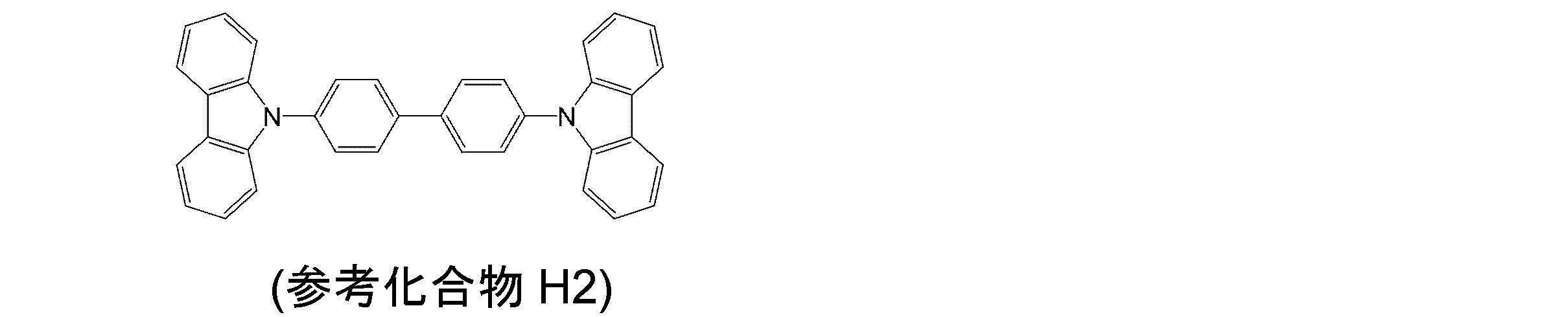
図3には、薄膜試料Aおよび薄膜試料Bについて測定した過渡PLから得た減衰曲線が示されている。
薄膜試料AおよびBともに、ドーピング材料として遅延蛍光発光性の化合物である化合物D1を用い、化合物D1がマトリックス材料中に分散した薄膜を有している。そのため、これら薄膜試料の共蒸着膜の過渡PLは、単一指数関数として観測されると考えられた。
しかしながら、薄膜試料Aの共蒸着膜の過渡PLについては、図3に示すように、減衰曲線の遅延蛍光由来の曲線部分が、非単一指数関数による発光成分として観測されている。これは、エキサイプレックスの発光準位と化合物D1の発光準位との間におけるエネルギー移動のやり取りが行われたため、非単一指数関数として観測されたと考えられる。
一方で、薄膜試料Bの共蒸着膜の過渡PLについては、図3に示すように、減衰曲線の遅延蛍光由来の曲線部分が、単一指数関数による発光成分として観測されている。そのため、参考化合物H2と化合物D1とは、エキサイプレックスを形成しにくい組み合わせであることが推測される。 FIG. 3 shows attenuation curves obtained from the transient PL measured for the thin film sample A and the thin film sample B.
Both of the thin film samples A and B have a thin film in which the compound D1 which is a delayed fluorescent compound is used as a doping material and the compound D1 is dispersed in the matrix material. Therefore, it was considered that the transient PL of the co-deposited film of these thin film samples was observed as a single exponential function.
However, for the transient PL of the co-deposited film of the thin film sample A, as shown in FIG. 3, the curve portion derived from delayed fluorescence of the decay curve is observed as a luminescent component by a non-single exponential function. This is considered to be observed as a non-single exponential function because of the exchange of energy transfer between the emission level of the exciplex and the emission level of the compound D1.
On the other hand, for the transient PL of the co-deposited film of the thin film sample B, as shown in FIG. 3, the curve portion derived from delayed fluorescence of the decay curve is observed as a luminescent component by a single exponential function. Therefore, it is speculated that the reference compound H2 and the compound D1 are a combination that hardly forms an exciplex.
以上の検討より、共蒸着膜の過渡PL発光スペクトルを観察し、マトリックス材料とドーピング材料とを適切な組合せで選択することで、ドーピング材料の三重項エネルギーをマトリックス材料が閉じ込めていることが確認された。一方、適切でない組合せを選択すると、マトリックス材料の三重項エネルギーが大きい場合であっても、マトリックス材料とドーピング材料のエキサイプレックスの形成によって、励起子の三重項エネルギーが効果的に閉じ込められなくなる事が確認できた。三重項エネルギーの閉じ込めが弱いと、減衰曲線において非単一指数関数として観測され、エキサイプレックスの形成による熱失活モードが増え、発光効率の低下につながると考えられる。上述のとおり、エキサイプレックスは、過渡PL発光スペクトルの長波長側に現れるため、エキサイプレックスは、元の分子よりも低い三重項エネルギーを有していると考えられる。つまり、三重項エネルギーの低いエキサイプレックス状態にエネルギーが移動し、非発光モードによる発光効率の低下を招来することが予測できる。
From the above study, it was confirmed that the matrix material confined the triplet energy of the doping material by observing the transient PL emission spectrum of the co-deposited film and selecting the matrix material and the doping material in an appropriate combination. It was. On the other hand, if an unsuitable combination is selected, even when the triplet energy of the matrix material is large, the exciplex formation of the matrix material and the doping material may prevent the exciton triplet energy from being effectively confined. It could be confirmed. If the triplet energy confinement is weak, it is observed as a non-single exponential function in the decay curve, and the heat deactivation mode due to the formation of the exciplex increases, leading to a decrease in luminous efficiency. As described above, since the exciplex appears on the long wavelength side of the transient PL emission spectrum, the exciplex is considered to have a triplet energy lower than that of the original molecule. That is, it can be predicted that the energy is transferred to an exciplex state having a low triplet energy, and that the light emission efficiency is lowered due to the non-light emission mode.
そして、上述の過渡PL測定の検討から、発光層中で第一の材料と第二の材料とが接してもエキサイプレックスを形成し難くなるように、第一の材料と第二の材料とを組み合わせることが重要であることが分かった。
本実施形態に係る第一の材料および第二の材料は、エキサイプレックスを形成し難くなるように化合物を選択して組み合わせることが好ましい。エキサイプレックスの形成は、上述のような共蒸着膜の過渡PL測定によって確認できる。
なお、本実施形態に係る第一の材料および第二の材料は、第一の材料の77[K]におけるエネルギーギャップT77K(M1)と、第二の材料の77[K]におけるエネルギーギャップT77K(M2)とが下記数式(数1)の関係を満たす化合物から選択されることが好ましい。77[K]におけるエネルギーギャップについては後述する。
T77K(M1) > T77K(M2) …(数1) Then, from the examination of the transient PL measurement described above, the first material and the second material are combined so that it is difficult to form an exciplex even if the first material and the second material are in contact with each other in the light emitting layer. It turns out that combining is important.
The first material and the second material according to the present embodiment are preferably selected and combined so that it is difficult to form an exciplex. Exciplex formation can be confirmed by transient PL measurement of the co-deposited film as described above.
The first material and the second material according to the present embodiment include an energy gap T 77K (M1) at 77 [K] of the first material and an energy gap T at 77 [K] of the second material. 77K (M2) is preferably selected from compounds satisfying the relationship of the following mathematical formula (Equation 1). The energy gap at 77 [K] will be described later.
T 77K (M1)> T 77K (M2) ( Equation 1)
・遅延蛍光発光性
過渡PL測定によって、縦軸を発光強度とし、横軸を時間とする発光減衰曲線を得ることができる。この発光減衰曲線に基づいて、光励起により生成した一重項励起状態から発光する蛍光と、三重項励起状態を経由して生成する一重項励起状態から発光する遅延蛍光との、蛍光強度比を見積もることができる。遅延蛍光発光性の材料では、素早く減衰する蛍光の強度に対し、緩やかに減衰する遅延蛍光の強度の割合が、ある程度大きい。本発明における遅延蛍光発光性の材料とは、室温で測定した発光減衰曲線において、光励起後から1マイクロ秒以降の発光強度を時間に対して積算した値が、1マイクロ秒以内の発光強度を時間に対して積算した値の5%以上である材料とする。
ただし、光励起により生成する励起状態の中で三重項励起状態の割合が極端に小さく、本来、遅延蛍光発光性の材料であっても遅延蛍光が微弱にしか観測されない場合がある。このような材料については、室温で三重項励起状態が基底状態へ緩和する過程において、一重項励起状態を経由して発光する割合が、無輻射失活する割合よりも大きい場合に遅延蛍光性の材料であるとする。なお、ここでの過渡PLの測定は、エキサイプレックスの形成や三重項励起状態の消光剤などが無い条件で行う必要がある。 Delayed fluorescence emission: By transient PL measurement, a light emission decay curve can be obtained with the vertical axis representing the emission intensity and the horizontal axis representing time. Based on this emission decay curve, estimate the fluorescence intensity ratio between the fluorescence emitted from the singlet excited state generated by photoexcitation and the delayed fluorescence emitted from the singlet excited state generated via the triplet excited state. Can do. In the delayed fluorescence emitting material, the ratio of the delayed fluorescence intensity that attenuates slowly is somewhat larger than the fluorescence intensity that decays quickly. The delayed fluorescent material in the present invention refers to an emission decay curve measured at room temperature, and a value obtained by integrating the emission intensity after 1 microsecond from the time after photoexcitation with respect to time indicates the emission intensity within 1 microsecond. The material is 5% or more of the integrated value.
However, the ratio of the triplet excited state among the excited states generated by photoexcitation is extremely small, and even in the case of a delayed fluorescence emitting material, delayed fluorescence may be observed only weakly. For such materials, in the process where the triplet excited state relaxes to the ground state at room temperature, when the rate of light emission via the singlet excited state is greater than the rate of non-radiation deactivation, Suppose that it is a material. Note that the transient PL measurement here needs to be performed under conditions where there is no formation of an exciplex or a quencher in a triplet excited state.
・イオン化ポテンシャルの関係性
一般的に、イオン化ポテンシャルが大きな材料をアクセプター分子と呼び、イオン化ポテンシャルの小さい材料をドナー分子と呼ぶ。アクセプター分子とドナー分子が隣接すると、エキサイプレックスを起こしやすいと考えられている。本実施形態に係る第二の材料は、強いアクセプター性であるCN基を有している。そのため、第二の材料と、有機EL素子の正孔輸送材料として一般的なアミン系材料とは、エキサイプレックスを形成しやすいと考えられる。
参考化合物H1と、第二の材料である化合物D1との組み合わせの場合は、マトリックス材料としての参考化合物H1のイオン化ポテンシャルよりも、ドーピング材料としての化合物D1のイオン化ポテンシャルの方が大きい。この場合、高い確率でエキサイプレックスを形成する。一方、参考化合物H2と化合物D1との組み合わせの場合は、化合物D1のイオン化ポテンシャルよりも、参考化合物H2のイオン化ポテンシャルの方が大きくなるため、エキサイプレックスの形成を効率良く阻止できる。参考化合物H1と参考化合物H2は共にジカルバゾール骨格を有する化合物であるが、一般的にカルバゾール骨格の結合の仕方により、ドナー性能が変わることが知られている。本参考例の場合、参考化合物H1の方が、イオン化ポテンシャルが小さく、ドナー性能が強い事が知られている。
さらに、下記参考化合物H3のイオン化ポテンシャルは、化合物D1のイオン化ポテンシャルよりも大きい。そのため、下記参考化合物H3と化合物D1との組み合わせにより、エキサイプレックスの形成を効率よく阻止することができる。 ・ Relationship of ionization potential Generally, a material with a large ionization potential is called an acceptor molecule, and a material with a low ionization potential is called a donor molecule. It is thought that an exciplex is likely to occur when an acceptor molecule and a donor molecule are adjacent to each other. The 2nd material which concerns on this embodiment has CN group which is strong acceptor property. Therefore, it is considered that the second material and a general amine material as a hole transport material of the organic EL element can easily form an exciplex.
In the case of the combination of the reference compound H1 and the compound D1 as the second material, the ionization potential of the compound D1 as the doping material is larger than the ionization potential of the reference compound H1 as the matrix material. In this case, an exciplex is formed with a high probability. On the other hand, in the case of the combination of the reference compound H2 and the compound D1, since the ionization potential of the reference compound H2 is larger than the ionization potential of the compound D1, the formation of an exciplex can be efficiently prevented. Both the reference compound H1 and the reference compound H2 are compounds having a dicarbazole skeleton, but it is generally known that the donor performance varies depending on how the carbazole skeleton is bonded. In the case of this reference example, it is known that the reference compound H1 has a lower ionization potential and stronger donor performance.
Furthermore, the ionization potential of the following reference compound H3 is larger than the ionization potential of the compound D1. Therefore, the combination of the following reference compound H3 and compound D1 can efficiently prevent the formation of an exciplex.

参考化合物H3のように、硫黄原子や酸素原子を含む環構造にさらに6員環構造が2つ以上縮合したような部分構造を有する化合物は、参考化合物H2のようなカルバゾール化合物よりもイオン化ポテンシャルが大きいため、エキサイプレックスを形成し難い。また、当該化合物は、三重項エネルギーが大きいため、ドーピング材料の三重項エネルギーを効率良く閉じ込めることができ、構造的にも強いため、長寿命化を図ることができる。
したがって、本実施形態の有機EL素子1では、前記数式(数1)の関係を満たすように、第一の材料として前記一般式(1)で表される部分構造を有する化合物と、前記第二の材料とを発光層に含有させることで、有機EL素子の発光効率を向上させ、寿命を延ばすことができる。 Like reference compound H3, a compound having a partial structure in which two or more six-membered ring structures are condensed to a ring structure containing a sulfur atom or an oxygen atom has an ionization potential higher than that of a carbazole compound such as reference compound H2. Due to its large size, it is difficult to form an exciplex. Further, since the compound has a large triplet energy, the triplet energy of the doping material can be efficiently confined and the structure is strong, so that the lifetime can be increased.
Therefore, in theorganic EL element 1 of the present embodiment, the compound having the partial structure represented by the general formula (1) as the first material so as to satisfy the relationship of the mathematical formula (Equation 1), and the second When the material is contained in the light emitting layer, the light emission efficiency of the organic EL element can be improved and the life can be extended.
したがって、本実施形態の有機EL素子1では、前記数式(数1)の関係を満たすように、第一の材料として前記一般式(1)で表される部分構造を有する化合物と、前記第二の材料とを発光層に含有させることで、有機EL素子の発光効率を向上させ、寿命を延ばすことができる。 Like reference compound H3, a compound having a partial structure in which two or more six-membered ring structures are condensed to a ring structure containing a sulfur atom or an oxygen atom has an ionization potential higher than that of a carbazole compound such as reference compound H2. Due to its large size, it is difficult to form an exciplex. Further, since the compound has a large triplet energy, the triplet energy of the doping material can be efficiently confined and the structure is strong, so that the lifetime can be increased.
Therefore, in the
また、本実施形態の有機EL素子1において、第一の材料のイオン化ポテンシャルIP(M1)よりも、第二の材料のイオン化ポテンシャルIP(M2)の方が小さくなるように組み合わせることが好ましい。すなわち、第一の材料のイオン化ポテンシャルIp(M1)と、第二の材料のイオン化ポテンシャルIp(M2)とが下記数式(数3)の関係を満たすことが好ましい。
In addition, in the organic EL element 1 of the present embodiment, it is preferable to combine so that the ionization potential IP (M2) of the second material is smaller than the ionization potential IP (M1) of the first material. That is, it is preferable that the ionization potential Ip (M1) of the first material and the ionization potential Ip (M2) of the second material satisfy the relationship of the following formula (Equation 3).
Ip(M1) > Ip(M2) …(数3)
Ip (M1)> Ip (M2) ... (Equation 3)
また、本実施形態において、第一の材料のイオン化ポテンシャルIp(M1)が、5.9eV以上であることが好ましい。
このような関係を満たすことで、エキサイプレックスの形成を抑制することができる。 In the present embodiment, the ionization potential Ip (M1) of the first material is preferably 5.9 eV or more.
By satisfying such a relationship, formation of an exciplex can be suppressed.
このような関係を満たすことで、エキサイプレックスの形成を抑制することができる。 In the present embodiment, the ionization potential Ip (M1) of the first material is preferably 5.9 eV or more.
By satisfying such a relationship, formation of an exciplex can be suppressed.
本実施形態において、シアノ基を有する第二の材料を用いる場合、第一の材料がアミン系化合物であると、エキサイプレックスを形成し易い。シアノ基を有する第二の材料は、イオン化ポテンシャルが大きく、アミン系化合物は、イオン化ポテンシャルが小さいため、発光層においてエキサイプレックスが形成されやすいと考えられる。
したがって、例えば、一つの分子中に前記一般式(2)で表される部分構造、および前記一般式(3)で表される部分構造を有する第二の材料を用いる場合には、第一の材料として、非アミン系化合物を用いることが好ましい。 In the present embodiment, when a second material having a cyano group is used, an exciplex is easily formed when the first material is an amine compound. The second material having a cyano group has a high ionization potential, and the amine compound has a low ionization potential. Therefore, it is considered that an exciplex is easily formed in the light emitting layer.
Therefore, for example, when a second material having a partial structure represented by the general formula (2) and a partial structure represented by the general formula (3) in one molecule is used, It is preferable to use a non-amine compound as the material.
なお、イオン化ポテンシャルの測定は、大気下で光電子分光装置を用いて測定することができる。具体的には、材料に光を照射し、その際に電荷分離によって生じる電子量を測定することにより測定した。測定装置としては、例えば、理研計器株式会社製の光電子分光装置(装置名:AC-3)などが挙げられる。
The ionization potential can be measured using a photoelectron spectrometer in the atmosphere. Specifically, the measurement was performed by irradiating the material with light and measuring the amount of electrons generated by charge separation at that time. Examples of the measuring device include a photoelectron spectrometer (device name: AC-3) manufactured by Riken Keiki Co., Ltd.
本実施形態における第一の材料は、三重項エネルギーが大きいため、発光層中に三重項エネルギーを効率よく閉じ込めることができる。また、本実施形態における第一の材料は、イオン化ポテンシャルが大きく、第二の材料とエキサイプレックスを形成し難く、三重項エネルギーの小さな会合体などを形成し難い材料である。そのため、本実施形態における第一の材料は、有機EL素子の発光効率を向上させることができる。
また、CN基を有する第二の材料は、アクセプター性が高く、電子をトラップして発光層内における電子の移動を妨げる傾向がある。そのため、第一の材料のホール輸送性が電子輸送性に対して相対的に高過ぎると、ホールや励起エネルギーが陰極や陰極側に形成された有機層に逃げ、発光効率が低下してしまう。本実施形態における第一の材料は、適度なホール輸送性と電子輸送性を有するため、発光効率をより一層向上させることができる。さらに第一の材料は、縮合環からなる剛直な構造を有するため、熱による化学的な変化や薄膜の物理的変化が少なく、有機EL素子を長寿命化させることができる。 Since the first material in this embodiment has a large triplet energy, the triplet energy can be efficiently confined in the light emitting layer. In addition, the first material in the present embodiment is a material that has a high ionization potential, does not easily form an exciplex with the second material, and does not easily form an association with a small triplet energy. Therefore, the first material in the present embodiment can improve the light emission efficiency of the organic EL element.
The second material having a CN group has a high acceptor property and tends to trap electrons and prevent movement of electrons in the light emitting layer. For this reason, if the hole transport property of the first material is too high relative to the electron transport property, holes and excitation energy escape to the cathode and the organic layer formed on the cathode side, and the light emission efficiency decreases. Since the 1st material in this embodiment has moderate hole transport property and electron transport property, it can improve luminous efficiency further. Furthermore, since the first material has a rigid structure composed of a condensed ring, there is little chemical change due to heat and physical change of the thin film, and the life of the organic EL element can be extended.
・ΔST
本実施形態の有機EL素子では、第二の材料の一重項エネルギーS(M2)と、第二の材料の77[K]におけるエネルギーギャップT77K(M2)との差ΔST(M2)が下記数式(数2)を満たすことが好ましい。
ΔST(M2)=S(M2)-T77K(M2)<0.3[eV] (数2)
また、ΔST(M2)は、0.2[eV]未満であることが好ましい。 ・ ΔST
In the organic EL element of the present embodiment, the difference ΔST (M2) between the singlet energy S (M2) of the second material and the energy gap T 77K (M2) at 77 [K] of the second material is expressed by the following formula. It is preferable to satisfy (Equation 2).
ΔST (M2) = S (M2) −T 77K (M2) <0.3 [eV] (Equation 2)
In addition, ΔST (M2) is preferably less than 0.2 [eV].
一重項エネルギーSと三重項エネルギーTの差に値するΔSTを小さくするには、量子化学的には、一重項エネルギーSと三重項エネルギーTにおける交換相互作用が小さいことで実現する。ΔSTと交換相互作用の関係性における物理的な詳細に関しては、例えば、次の参考文献1や参考文献2に記載されている。
参考文献1:安達千波矢ら、有機EL討論会 第10回例会予稿集、S2-5,p11~12
参考文献2:徳丸克己、有機光化学反応論、東京化学同人出版、(1973)
このような材料は、量子計算により分子設計を行い合成することが可能であり、具体的には、LUMO、及びHOMOの電子軌道を重ねないように局在化させた化合物である。
本実施形態の第二の材料に用いるΔSTの小さな化合物の例としては、分子内でドナー要素とアクセプター要素とを結合した化合物であり、さらに電気化学的な安定性(酸化還元安定性)を考慮し、ΔSTが0eV以上0.3eV未満の化合物が挙げられる。
また、より好ましい化合物は、分子の励起状態で形成される双極子(ダイポール)が互いに相互作用し、交換相互作用エネルギーが小さくなるような会合体を形成する化合物である。本発明者らの検討によれば、このような化合物は、双極子(ダイポール)の方向がおおよそ揃い、分子の相互作用により、さらにΔSTが小さくなり得る。このような場合、ΔSTは、0eV以上0.2eV以下と極めて小さくなり得る。 In order to reduce ΔST that is equivalent to the difference between the singlet energy S and the triplet energy T, quantum exchange is realized by a small exchange interaction between the singlet energy S and the triplet energy T. The physical details of the relationship between ΔST and exchange interaction are described in, for example, the followingReference 1 and Reference 2.
Reference 1: Chitaya Adachi et al., Organic EL Discussion Group 10th Annual Meeting Proceedings, S2-5, p11-12
Reference 2: Katsumi Tokumaru, Organic Photochemical Reaction Theory, Tokyo Kagaku Doujin Publishing, (1973)
Such a material can be synthesized by molecular design by quantum calculation. Specifically, it is a compound localized so as not to overlap the LUMO and HOMO electron orbitals.
An example of a compound having a small ΔST used for the second material of the present embodiment is a compound in which a donor element and an acceptor element are combined in the molecule, and further, electrochemical stability (redox stability) is considered. And compounds having ΔST of 0 eV or more and less than 0.3 eV.
Further, a more preferable compound is a compound that forms an aggregate in which dipoles formed in an excited state of a molecule interact with each other and exchange interaction energy becomes small. According to the study by the present inventors, such a compound has approximately the same dipole direction, and ΔST can be further reduced by molecular interaction. In such a case, ΔST can be extremely small, from 0 eV to 0.2 eV.
参考文献1:安達千波矢ら、有機EL討論会 第10回例会予稿集、S2-5,p11~12
参考文献2:徳丸克己、有機光化学反応論、東京化学同人出版、(1973)
このような材料は、量子計算により分子設計を行い合成することが可能であり、具体的には、LUMO、及びHOMOの電子軌道を重ねないように局在化させた化合物である。
本実施形態の第二の材料に用いるΔSTの小さな化合物の例としては、分子内でドナー要素とアクセプター要素とを結合した化合物であり、さらに電気化学的な安定性(酸化還元安定性)を考慮し、ΔSTが0eV以上0.3eV未満の化合物が挙げられる。
また、より好ましい化合物は、分子の励起状態で形成される双極子(ダイポール)が互いに相互作用し、交換相互作用エネルギーが小さくなるような会合体を形成する化合物である。本発明者らの検討によれば、このような化合物は、双極子(ダイポール)の方向がおおよそ揃い、分子の相互作用により、さらにΔSTが小さくなり得る。このような場合、ΔSTは、0eV以上0.2eV以下と極めて小さくなり得る。 In order to reduce ΔST that is equivalent to the difference between the singlet energy S and the triplet energy T, quantum exchange is realized by a small exchange interaction between the singlet energy S and the triplet energy T. The physical details of the relationship between ΔST and exchange interaction are described in, for example, the following
Reference 1: Chitaya Adachi et al., Organic EL Discussion Group 10th Annual Meeting Proceedings, S2-5, p11-12
Reference 2: Katsumi Tokumaru, Organic Photochemical Reaction Theory, Tokyo Kagaku Doujin Publishing, (1973)
Such a material can be synthesized by molecular design by quantum calculation. Specifically, it is a compound localized so as not to overlap the LUMO and HOMO electron orbitals.
An example of a compound having a small ΔST used for the second material of the present embodiment is a compound in which a donor element and an acceptor element are combined in the molecule, and further, electrochemical stability (redox stability) is considered. And compounds having ΔST of 0 eV or more and less than 0.3 eV.
Further, a more preferable compound is a compound that forms an aggregate in which dipoles formed in an excited state of a molecule interact with each other and exchange interaction energy becomes small. According to the study by the present inventors, such a compound has approximately the same dipole direction, and ΔST can be further reduced by molecular interaction. In such a case, ΔST can be extremely small, from 0 eV to 0.2 eV.
・TADF機構
前述したとおり、第二の材料のΔST(M2)が小さいと、外部から与えられる熱エネルギーによって、第二の材料の三重項準位から第二の材料の一重項準位への逆項間交差が起こり易くなる。有機EL素子内部の電気励起された励起子の励起三重項状態が、逆項間交差によって、励起一重項状態へスピン交換がされるエネルギー状態変換機構をTADF機構と呼ぶ。
本実施形態の有機EL素子では、第二の材料としてΔST(M2)が小さい化合物を用いることが好ましく、外部から与えられる熱エネルギーによって、第二の材料の三重項準位から第二の材料の一重項準位への逆項間交差が起こり易くなる。
図4は、発光層における第二の材料と第一の材料とのエネルギー準位の関係の一例を示す。図4において、S0は、基底状態を表し、S1Hは、第一の材料の最低励起一重項状態を表し、T1Hは、第一の材料の最低励起三重項状態を表し、S1Dは、第二の材料の最低励起一重項状態を表し、T1Dは、第二の材料の最低励起三重項状態を表し、破線の矢印は、各励起状態間のエネルギー移動を表す。図4に示すように、第二の材料としてΔST(M2)の小さな材料を用いることにより、第一の材料の最低励起三重項状態T1Hからのデクスター移動により第二の材料の最低励起一重項状態S1Dまたは最低励起三重項状態T1Dにエネルギー移動する。さらに第二の材料の最低励起三重項状態T1Dは、熱エネルギーにより、最低励起一重項状態S1Dに逆項間交差が可能である。この結果、第二の材料の最低励起一重項状態S1Dからの蛍光発光を観測することができる。このTADF機構による遅延蛍光を利用することによっても、理論的に内部効率を100%まで高めることができると考えられている。
なお、本発明は、図4に示したような第二の材料と第一の材料のエネルギー準位の関係に限定されない。例えば、ΔST(M2)の小さな第二の材料を用いることで、熱エネルギーにより最低励起三重項状態T1Dから最低励起一重項状態S1Dに逆項間交差を起こり易くさせ、第二の材料の最低励起一重項状態S1Dから、第一の材料の最低励起一重項状態S1Hへエネルギー移動させるように発光層を構成してもよい。 TADF mechanism As described above, when ΔST (M2) of the second material is small, the reverse from the triplet level of the second material to the singlet level of the second material due to the externally applied thermal energy. Interterm crossing is likely to occur. An energy state conversion mechanism in which the excited triplet state of the electrically excited exciton inside the organic EL element is spin-exchanged to the excited singlet state by crossing between inverse terms is called a TADF mechanism.
In the organic EL element of the present embodiment, it is preferable to use a compound having a small ΔST (M2) as the second material, and from the triplet level of the second material to the second material by heat energy given from the outside. Inverse crossing to singlet levels easily occurs.
FIG. 4 shows an example of the energy level relationship between the second material and the first material in the light emitting layer. In FIG. 4, S0 represents the ground state, S1 H represents the lowest excited singlet state of the first material, T1 H represents the lowest excited triplet state of the first material, and S1 D represents The lowest excited singlet state of the second material is represented, T1 D represents the lowest excited triplet state of the second material, and the dashed arrow represents the energy transfer between each excited state. As shown in FIG. 4, by using a material having a small ΔST (M2) as the second material, the lowest excited singlet of the second material is caused by Dexter movement from the lowest excited triplet state T1 H of the first material. Energy transfer to state S1 D or lowest excited triplet state T1 D. Further lowest excited triplet state T1 D of the second material, by thermal energy, it is possible Gyakuko intersystem crossing to the lowest excited singlet state S1 D. As a result, it is possible to observe the fluorescence emission from the lowest excited singlet state S1 D of the second material. It is believed that the internal efficiency can theoretically be increased to 100% also by utilizing delayed fluorescence due to this TADF mechanism.
The present invention is not limited to the relationship between the energy levels of the second material and the first material as shown in FIG. For example, by using a small second material .DELTA.St (M2), the lowest excited singlet state S1 D from the lowest excited triplet state T1 D by thermal energy is likely to occur a cross between Gyakuko, the second material The light emitting layer may be configured to transfer energy from the lowest excited singlet state S1 D to the lowest excited singlet state S1 H of the first material.
・三重項エネルギーと77[K]におけるエネルギーギャップとの関係
ここで、三重項エネルギーと77[K]におけるエネルギーギャップとの関係について説明する。本実施形態では、77[K]におけるエネルギーギャップは、通常定義される三重項エネルギーとは異なる点がある。
三重項エネルギーの測定は、次のようにして行われる。まず、測定対象となる化合物を石英基板上に蒸着した試料、または適切な溶媒中に溶解した溶液を石英ガラス管内に封入した試料を作製する。この試料について、低温(77[K])で燐光スペクトル(縦軸:燐光発光強度、横軸:波長とする。)を測定し、この燐光スペクトルの短波長側の立ち上がりに対して接線を引き、その接線と横軸との交点の波長値に基づいて、所定の換算式から三重項エネルギーを算出する。
ここで、本実施形態に用いる化合物としては、ΔSTが小さい化合物であることが好ましい。ΔSTが小さいと、低温(77[K])状態でも、項間交差、及び逆項間交差が起こりやすく、励起一重項状態と励起三重項状態とが混在する。その結果、上記と同様にして測定されるスペクトルは、励起一重項状態および励起三重項状態の両者からの発光を含んでおり、いずれの状態から発光したかについて峻別することは困難であるが、基本的には三重項エネルギーの値が支配的と考えられる。
そのため、本実施形態では、通常の三重項エネルギーTと測定手法は同じであるが、その厳密な意味において異なることを区別するため、次のようにして測定される値をエネルギーギャップT77Kと称する。薄膜を用いて測定する場合には、測定対象となる化合物を石英基板上に膜厚100nmで蒸着して試料を作製する。この試料について、低温(77[K])で燐光スペクトル(縦軸:燐光発光強度、横軸:波長とする。)を測定し、この燐光スペクトルの短波長側の立ち上がりに対して接線を引き、その接線と横軸との交点の波長値λedge[nm]に基づいて、次の換算式1から算出されるエネルギー量をエネルギーギャップT77Kとする。
換算式1:T77K[eV]=1239.85/λedge
燐光スペクトルの短波長側の立ち上がりに対する接線は以下のように引く。燐光スペクトルの短波長側から、スペクトルの極大値のうち、最も短波長側の極大値までスペクトル曲線上を移動する際に、長波長側に向けて曲線上の各点における接線を考える。この接線は、曲線が立ち上がるにつれ(つまり縦軸が増加するにつれ)、傾きが増加する。この傾きの値が極大値をとる点において引いた接線(すなわち変曲点における接線)が、当該燐光スペクトルの短波長側の立ち上がりに対する接線とする。
なお、スペクトルの最大ピーク強度の15%以下のピーク強度をもつ極大点は、上述の最も短波長側の極大値には含めず、最も短波長側の極大値に最も近い、傾きの値が極大値をとる点において引いた接線を当該燐光スペクトルの短波長側の立ち上がりに対する接線とする。
燐光の測定には、(株)日立ハイテクノロジー製のF-4500形分光蛍光光度計本体を用いることができる。なお、測定装置はこの限りではなく、冷却装置及び低温用容器と、励起光源と、受光装置とを組み合わせることにより、測定してもよい。 -Relationship between triplet energy and energy gap at 77 [K] Here, the relationship between triplet energy and energy gap at 77 [K] will be described. In the present embodiment, the energy gap at 77 [K] is different from the normally defined triplet energy.
The triplet energy is measured as follows. First, a sample in which a compound to be measured is deposited on a quartz substrate or a sample in which a solution dissolved in an appropriate solvent is enclosed in a quartz glass tube is prepared. With respect to this sample, a phosphorescence spectrum (vertical axis: phosphorescence emission intensity, horizontal axis: wavelength) is measured at a low temperature (77 [K]), and a tangent line is drawn with respect to the rising edge on the short wavelength side of the phosphorescence spectrum, Based on the wavelength value at the intersection of the tangent and the horizontal axis, triplet energy is calculated from a predetermined conversion formula.
Here, the compound used in this embodiment is preferably a compound having a small ΔST. When ΔST is small, intersystem crossing and reverse intersystem crossing easily occur even in a low temperature (77 [K]) state, and an excited singlet state and an excited triplet state are mixed. As a result, the spectrum measured in the same manner as described above includes light emission from both the excited singlet state and the excited triplet state, and it is difficult to distinguish clearly from which state the light is emitted. Basically, the triplet energy value is considered dominant.
Therefore, in this embodiment, the normal triplet energy T and the measurement method are the same, but in order to distinguish the difference in the strict meaning, a value measured as follows is referred to as an energy gap T 77K. . In the case of measuring using a thin film, a sample is prepared by vapor-depositing a compound to be measured on a quartz substrate with a thickness of 100 nm. With respect to this sample, a phosphorescence spectrum (vertical axis: phosphorescence emission intensity, horizontal axis: wavelength) is measured at a low temperature (77 [K]), and a tangent line is drawn with respect to the rising edge on the short wavelength side of the phosphorescence spectrum, Based on the wavelength value λ edge [nm] at the intersection of the tangent and the horizontal axis, the energy amount calculated from the followingconversion formula 1 is defined as an energy gap T 77K .
Conversion formula 1: T 77K [eV] = 1239.85 / λ edge
The tangent to the rising edge on the short wavelength side of the phosphorescence spectrum is drawn as follows. When moving on the spectrum curve from the short wavelength side of the phosphorescence spectrum to the maximum value on the shortest wavelength side among the maximum values of the spectrum, tangents at each point on the curve are considered toward the long wavelength side. The slope of this tangent line increases as the curve rises (that is, as the vertical axis increases). A tangent drawn at a point where the value of the slope takes a maximum value (that is, a tangent at the inflection point) is a tangent to the rising edge of the phosphorescence spectrum on the short wavelength side.
Note that the maximum point having a peak intensity of 15% or less of the maximum peak intensity of the spectrum is not included in the above-mentioned maximum value on the shortest wavelength side, and has the maximum slope value closest to the maximum value on the shortest wavelength side. The tangent drawn at the point where the value is taken is taken as the tangent to the rising edge of the phosphorescence spectrum on the short wavelength side.
For measurement of phosphorescence, an F-4500 type spectrofluorometer main body manufactured by Hitachi High-Technology Co., Ltd. can be used. Note that the measurement device is not limited to this, and the measurement may be performed by combining a cooling device and a cryogenic container, an excitation light source, and a light receiving device.
ここで、三重項エネルギーと77[K]におけるエネルギーギャップとの関係について説明する。本実施形態では、77[K]におけるエネルギーギャップは、通常定義される三重項エネルギーとは異なる点がある。
三重項エネルギーの測定は、次のようにして行われる。まず、測定対象となる化合物を石英基板上に蒸着した試料、または適切な溶媒中に溶解した溶液を石英ガラス管内に封入した試料を作製する。この試料について、低温(77[K])で燐光スペクトル(縦軸:燐光発光強度、横軸:波長とする。)を測定し、この燐光スペクトルの短波長側の立ち上がりに対して接線を引き、その接線と横軸との交点の波長値に基づいて、所定の換算式から三重項エネルギーを算出する。
ここで、本実施形態に用いる化合物としては、ΔSTが小さい化合物であることが好ましい。ΔSTが小さいと、低温(77[K])状態でも、項間交差、及び逆項間交差が起こりやすく、励起一重項状態と励起三重項状態とが混在する。その結果、上記と同様にして測定されるスペクトルは、励起一重項状態および励起三重項状態の両者からの発光を含んでおり、いずれの状態から発光したかについて峻別することは困難であるが、基本的には三重項エネルギーの値が支配的と考えられる。
そのため、本実施形態では、通常の三重項エネルギーTと測定手法は同じであるが、その厳密な意味において異なることを区別するため、次のようにして測定される値をエネルギーギャップT77Kと称する。薄膜を用いて測定する場合には、測定対象となる化合物を石英基板上に膜厚100nmで蒸着して試料を作製する。この試料について、低温(77[K])で燐光スペクトル(縦軸:燐光発光強度、横軸:波長とする。)を測定し、この燐光スペクトルの短波長側の立ち上がりに対して接線を引き、その接線と横軸との交点の波長値λedge[nm]に基づいて、次の換算式1から算出されるエネルギー量をエネルギーギャップT77Kとする。
換算式1:T77K[eV]=1239.85/λedge
燐光スペクトルの短波長側の立ち上がりに対する接線は以下のように引く。燐光スペクトルの短波長側から、スペクトルの極大値のうち、最も短波長側の極大値までスペクトル曲線上を移動する際に、長波長側に向けて曲線上の各点における接線を考える。この接線は、曲線が立ち上がるにつれ(つまり縦軸が増加するにつれ)、傾きが増加する。この傾きの値が極大値をとる点において引いた接線(すなわち変曲点における接線)が、当該燐光スペクトルの短波長側の立ち上がりに対する接線とする。
なお、スペクトルの最大ピーク強度の15%以下のピーク強度をもつ極大点は、上述の最も短波長側の極大値には含めず、最も短波長側の極大値に最も近い、傾きの値が極大値をとる点において引いた接線を当該燐光スペクトルの短波長側の立ち上がりに対する接線とする。
燐光の測定には、(株)日立ハイテクノロジー製のF-4500形分光蛍光光度計本体を用いることができる。なお、測定装置はこの限りではなく、冷却装置及び低温用容器と、励起光源と、受光装置とを組み合わせることにより、測定してもよい。 -Relationship between triplet energy and energy gap at 77 [K] Here, the relationship between triplet energy and energy gap at 77 [K] will be described. In the present embodiment, the energy gap at 77 [K] is different from the normally defined triplet energy.
The triplet energy is measured as follows. First, a sample in which a compound to be measured is deposited on a quartz substrate or a sample in which a solution dissolved in an appropriate solvent is enclosed in a quartz glass tube is prepared. With respect to this sample, a phosphorescence spectrum (vertical axis: phosphorescence emission intensity, horizontal axis: wavelength) is measured at a low temperature (77 [K]), and a tangent line is drawn with respect to the rising edge on the short wavelength side of the phosphorescence spectrum, Based on the wavelength value at the intersection of the tangent and the horizontal axis, triplet energy is calculated from a predetermined conversion formula.
Here, the compound used in this embodiment is preferably a compound having a small ΔST. When ΔST is small, intersystem crossing and reverse intersystem crossing easily occur even in a low temperature (77 [K]) state, and an excited singlet state and an excited triplet state are mixed. As a result, the spectrum measured in the same manner as described above includes light emission from both the excited singlet state and the excited triplet state, and it is difficult to distinguish clearly from which state the light is emitted. Basically, the triplet energy value is considered dominant.
Therefore, in this embodiment, the normal triplet energy T and the measurement method are the same, but in order to distinguish the difference in the strict meaning, a value measured as follows is referred to as an energy gap T 77K. . In the case of measuring using a thin film, a sample is prepared by vapor-depositing a compound to be measured on a quartz substrate with a thickness of 100 nm. With respect to this sample, a phosphorescence spectrum (vertical axis: phosphorescence emission intensity, horizontal axis: wavelength) is measured at a low temperature (77 [K]), and a tangent line is drawn with respect to the rising edge on the short wavelength side of the phosphorescence spectrum, Based on the wavelength value λ edge [nm] at the intersection of the tangent and the horizontal axis, the energy amount calculated from the following
Conversion formula 1: T 77K [eV] = 1239.85 / λ edge
The tangent to the rising edge on the short wavelength side of the phosphorescence spectrum is drawn as follows. When moving on the spectrum curve from the short wavelength side of the phosphorescence spectrum to the maximum value on the shortest wavelength side among the maximum values of the spectrum, tangents at each point on the curve are considered toward the long wavelength side. The slope of this tangent line increases as the curve rises (that is, as the vertical axis increases). A tangent drawn at a point where the value of the slope takes a maximum value (that is, a tangent at the inflection point) is a tangent to the rising edge of the phosphorescence spectrum on the short wavelength side.
Note that the maximum point having a peak intensity of 15% or less of the maximum peak intensity of the spectrum is not included in the above-mentioned maximum value on the shortest wavelength side, and has the maximum slope value closest to the maximum value on the shortest wavelength side. The tangent drawn at the point where the value is taken is taken as the tangent to the rising edge of the phosphorescence spectrum on the short wavelength side.
For measurement of phosphorescence, an F-4500 type spectrofluorometer main body manufactured by Hitachi High-Technology Co., Ltd. can be used. Note that the measurement device is not limited to this, and the measurement may be performed by combining a cooling device and a cryogenic container, an excitation light source, and a light receiving device.
・一重項エネルギーS
一重項エネルギーSは、次のようにして測定される。
測定対象となる化合物を石英基板上に膜厚100nmで蒸着して試料を作製し、常温(300K)でこの試料の発光スペクトル(縦軸:発光強度、横軸:波長とする。)を測定する。この発光スペクトルの短波長側の立ち上がりに対して接線を引き、その接線と横軸との交点の波長値λedge[nm]に基づいて、次に示す換算式2から算出される。
換算式2:S[eV]=1239.85/λedge
吸収スペクトルは、分光光度計で測定する。例えば、日立社製の分光光度計(装置名:U3310)等を用いることができる。 ・ Singlet energy S
The singlet energy S is measured as follows.
A sample to be measured is deposited on a quartz substrate with a film thickness of 100 nm to prepare a sample, and the emission spectrum (vertical axis: emission intensity, horizontal axis: wavelength) of this sample is measured at room temperature (300 K). . A tangent line is drawn with respect to the rise of the emission spectrum on the short wavelength side, and is calculated from the followingconversion formula 2 based on the wavelength value λ edge [nm] at the intersection of the tangent line and the horizontal axis.
Conversion formula 2: S [eV] = 1239.85 / λ edge
The absorption spectrum is measured with a spectrophotometer. For example, a Hitachi spectrophotometer (device name: U3310) or the like can be used.
一重項エネルギーSは、次のようにして測定される。
測定対象となる化合物を石英基板上に膜厚100nmで蒸着して試料を作製し、常温(300K)でこの試料の発光スペクトル(縦軸:発光強度、横軸:波長とする。)を測定する。この発光スペクトルの短波長側の立ち上がりに対して接線を引き、その接線と横軸との交点の波長値λedge[nm]に基づいて、次に示す換算式2から算出される。
換算式2:S[eV]=1239.85/λedge
吸収スペクトルは、分光光度計で測定する。例えば、日立社製の分光光度計(装置名:U3310)等を用いることができる。 ・ Singlet energy S
The singlet energy S is measured as follows.
A sample to be measured is deposited on a quartz substrate with a film thickness of 100 nm to prepare a sample, and the emission spectrum (vertical axis: emission intensity, horizontal axis: wavelength) of this sample is measured at room temperature (300 K). . A tangent line is drawn with respect to the rise of the emission spectrum on the short wavelength side, and is calculated from the following
Conversion formula 2: S [eV] = 1239.85 / λ edge
The absorption spectrum is measured with a spectrophotometer. For example, a Hitachi spectrophotometer (device name: U3310) or the like can be used.
発光スペクトルの短波長側の立ち上がりに対する接線は以下のように引く。発光スペクトルの短波長側から、スペクトルの極大値のうち、最も短波長側の極大値までスペクトル曲線上を移動する際に、長波長側に向けて曲線上の各点における接線を考える。この接線は、曲線が立ち上がるにつれ(つまり縦軸が増加するにつれ)、傾きが増加する。この傾きの値が極大値をとる点において引いた接線(すなわち変曲点における接線)が、当該発光スペクトルの短波長側の立ち上がりに対する接線とする。
なお、石英基板上に蒸着した試料を用いた測定結果と、溶液を用いた測定結果とが大きく異なる場合には、その原因として分子の会合体の形成や溶媒との強い相互作用などが考えられる。そのため、測定対象となる化合物と、エネルギーギャップが大きくエキサイプレックスを形成しない適切な他の材料とを、石英基板上に共蒸着した試料を用いて上記の測定を行うこともできる。 A tangent to the rising edge of the emission spectrum on the short wavelength side is drawn as follows. When moving on the spectrum curve from the short wavelength side of the emission spectrum to the maximum value on the shortest wavelength side of the maximum value of the spectrum, tangents at each point on the curve are considered toward the long wavelength side. The slope of this tangent line increases as the curve rises (that is, as the vertical axis increases). The tangent drawn at the point where the value of the slope takes the maximum value (that is, the tangent at the inflection point) is the tangent to the short wavelength side rise of the emission spectrum.
In addition, when the measurement result using the sample deposited on the quartz substrate and the measurement result using the solution are greatly different, the cause may be the formation of molecular aggregates or strong interaction with the solvent. . Therefore, the above measurement can also be performed using a sample in which a compound to be measured and another appropriate material having a large energy gap and not forming an exciplex are co-deposited on a quartz substrate.
本実施形態では、一重項エネルギーSとエネルギーギャップT77Kとの差をΔSTとして定義する。
In the present embodiment, the difference between the singlet energy S and the energy gap T 77K is defined as ΔST.
本実施形態の有機EL素子において、発光層に含有されている第二の材料が発光することが好ましい。
また、本実施形態の有機EL素子において、発光層には金属錯体が含有されていないことが好ましい。 In the organic EL device of the present embodiment, it is preferable that the second material contained in the light emitting layer emits light.
Moreover, in the organic EL element of this embodiment, it is preferable that the light emitting layer does not contain a metal complex.
(基板)
基板は、有機EL素子の支持体として用いられる。基板としては、例えば、ガラス、石英、プラスチックなどを用いることができる。また、可撓性基板を用いてもよい。可撓性基板とは、折り曲げることができる(フレキシブル)基板のことであり、例えば、ポリカーボネート、ポリアリレート、ポリエーテルスルフォン、ポリプロピレン、ポリエステル、ポリフッ化ビニル、ポリ塩化ビニルからなるプラスチック基板等が挙げられる。また、無機蒸着フィルムを用いることもできる。 (substrate)
The substrate is used as a support for the organic EL element. For example, glass, quartz, plastic, or the like can be used as the substrate. Further, a flexible substrate may be used. The flexible substrate is a substrate that can be bent (flexible), and examples thereof include plastic substrates made of polycarbonate, polyarylate, polyethersulfone, polypropylene, polyester, polyvinyl fluoride, and polyvinyl chloride. . Moreover, an inorganic vapor deposition film can also be used.
(陽極)
基板上に形成される陽極には、仕事関数の大きい(具体的には4.0eV以上)金属、合金、電気伝導性化合物、およびこれらの混合物などを用いることが好ましい。具体的には、例えば、酸化インジウム-酸化スズ(ITO:Indium Tin Oxide)、珪素若しくは酸化珪素を含有した酸化インジウム-酸化スズ、酸化インジウム-酸化亜鉛、酸化タングステン、および酸化亜鉛を含有した酸化インジウム、グラフェン等が挙げられる。この他、金(Au)、白金(Pt)、ニッケル(Ni)、タングステン(W)、クロム(Cr)、モリブデン(Mo)、鉄(Fe)、コバルト(Co)、銅(Cu)、パラジウム(Pd)、チタン(Ti)、または金属材料の窒化物(例えば、窒化チタン)等が挙げられる。
これらの材料は、通常、スパッタリング法により成膜される。例えば、酸化インジウム-酸化亜鉛は、酸化インジウムに対し1質量%以上10質量%以下の酸化亜鉛を加えたターゲットを用いることにより、スパッタリング法で形成することができる。また、例えば、酸化タングステン、および酸化亜鉛を含有した酸化インジウムは、酸化インジウムに対し酸化タングステンを0.5質量%以上5質量%以下、酸化亜鉛を0.1質量%以上1質量%以下含有したターゲットを用いることにより、スパッタリング法で形成することができる。その他、真空蒸着法、塗布法、インクジェット法、スピンコート法などにより作製してもよい。
陽極上に形成されるEL層のうち、陽極に接して形成される正孔注入層は、陽極の仕事関数に関係なく正孔(ホール)注入が容易である複合材料を用いて形成されるため、電極材料として可能な材料(例えば、金属、合金、電気伝導性化合物、およびこれらの混合物、その他、元素周期表の第1族または第2族に属する元素も含む)を用いることができる。
仕事関数の小さい材料である、元素周期表の第1族または第2族に属する元素、すなわちリチウム(Li)やセシウム(Cs)等のアルカリ金属、およびマグネシウム(Mg)、カルシウム(Ca)、ストロンチウム(Sr)等のアルカリ土類金属、およびこれらを含む合金(例えば、MgAg、AlLi)、ユーロピウム(Eu)、イッテルビウム(Yb)等の希土類金属およびこれらを含む合金等を用いることもできる。なお、アルカリ金属、アルカリ土類金属、およびこれらを含む合金を用いて陽極を形成する場合には、真空蒸着法やスパッタリング法を用いることができる。さらに、銀ペーストなどを用いる場合には、塗布法やインクジェット法などを用いることができる。 (anode)
For the anode formed on the substrate, it is preferable to use a metal, an alloy, an electrically conductive compound, a mixture thereof, or the like having a high work function (specifically, 4.0 eV or more). Specifically, for example, indium tin oxide (ITO), indium oxide-tin oxide containing silicon or silicon oxide, indium oxide-zinc oxide, tungsten oxide, and indium oxide containing zinc oxide. And graphene. In addition, gold (Au), platinum (Pt), nickel (Ni), tungsten (W), chromium (Cr), molybdenum (Mo), iron (Fe), cobalt (Co), copper (Cu), palladium ( Pd), titanium (Ti), or a metal material nitride (for example, titanium nitride).
These materials are usually formed by sputtering. For example, indium oxide-zinc oxide can be formed by a sputtering method by using a target in which 1% by mass to 10% by mass of zinc oxide is added to indium oxide. For example, indium oxide containing tungsten oxide and zinc oxide contains 0.5% by mass to 5% by mass of tungsten oxide and 0.1% by mass to 1% by mass of zinc oxide with respect to indium oxide. By using a target, it can be formed by a sputtering method. In addition, you may produce by the vacuum evaporation method, the apply | coating method, the inkjet method, a spin coat method, etc.
Of the EL layers formed on the anode, the hole injection layer formed in contact with the anode is formed using a composite material that facilitates hole injection regardless of the work function of the anode. Any material that can be used as an electrode material (for example, a metal, an alloy, an electrically conductive compound, and a mixture thereof, and other elements belonging toGroup 1 or Group 2 of the periodic table) can be used.
An element belonging toGroup 1 or Group 2 of the periodic table, which is a material having a low work function, that is, an alkali metal such as lithium (Li) or cesium (Cs), and magnesium (Mg), calcium (Ca), or strontium Alkaline earth metals such as (Sr), and alloys containing these (eg, MgAg, AlLi), rare earth metals such as europium (Eu), ytterbium (Yb), and alloys containing these can also be used. Note that when an anode is formed using an alkali metal, an alkaline earth metal, and an alloy containing these, a vacuum evaporation method or a sputtering method can be used. Furthermore, when using a silver paste etc., the apply | coating method, the inkjet method, etc. can be used.
基板上に形成される陽極には、仕事関数の大きい(具体的には4.0eV以上)金属、合金、電気伝導性化合物、およびこれらの混合物などを用いることが好ましい。具体的には、例えば、酸化インジウム-酸化スズ(ITO:Indium Tin Oxide)、珪素若しくは酸化珪素を含有した酸化インジウム-酸化スズ、酸化インジウム-酸化亜鉛、酸化タングステン、および酸化亜鉛を含有した酸化インジウム、グラフェン等が挙げられる。この他、金(Au)、白金(Pt)、ニッケル(Ni)、タングステン(W)、クロム(Cr)、モリブデン(Mo)、鉄(Fe)、コバルト(Co)、銅(Cu)、パラジウム(Pd)、チタン(Ti)、または金属材料の窒化物(例えば、窒化チタン)等が挙げられる。
これらの材料は、通常、スパッタリング法により成膜される。例えば、酸化インジウム-酸化亜鉛は、酸化インジウムに対し1質量%以上10質量%以下の酸化亜鉛を加えたターゲットを用いることにより、スパッタリング法で形成することができる。また、例えば、酸化タングステン、および酸化亜鉛を含有した酸化インジウムは、酸化インジウムに対し酸化タングステンを0.5質量%以上5質量%以下、酸化亜鉛を0.1質量%以上1質量%以下含有したターゲットを用いることにより、スパッタリング法で形成することができる。その他、真空蒸着法、塗布法、インクジェット法、スピンコート法などにより作製してもよい。
陽極上に形成されるEL層のうち、陽極に接して形成される正孔注入層は、陽極の仕事関数に関係なく正孔(ホール)注入が容易である複合材料を用いて形成されるため、電極材料として可能な材料(例えば、金属、合金、電気伝導性化合物、およびこれらの混合物、その他、元素周期表の第1族または第2族に属する元素も含む)を用いることができる。
仕事関数の小さい材料である、元素周期表の第1族または第2族に属する元素、すなわちリチウム(Li)やセシウム(Cs)等のアルカリ金属、およびマグネシウム(Mg)、カルシウム(Ca)、ストロンチウム(Sr)等のアルカリ土類金属、およびこれらを含む合金(例えば、MgAg、AlLi)、ユーロピウム(Eu)、イッテルビウム(Yb)等の希土類金属およびこれらを含む合金等を用いることもできる。なお、アルカリ金属、アルカリ土類金属、およびこれらを含む合金を用いて陽極を形成する場合には、真空蒸着法やスパッタリング法を用いることができる。さらに、銀ペーストなどを用いる場合には、塗布法やインクジェット法などを用いることができる。 (anode)
For the anode formed on the substrate, it is preferable to use a metal, an alloy, an electrically conductive compound, a mixture thereof, or the like having a high work function (specifically, 4.0 eV or more). Specifically, for example, indium tin oxide (ITO), indium oxide-tin oxide containing silicon or silicon oxide, indium oxide-zinc oxide, tungsten oxide, and indium oxide containing zinc oxide. And graphene. In addition, gold (Au), platinum (Pt), nickel (Ni), tungsten (W), chromium (Cr), molybdenum (Mo), iron (Fe), cobalt (Co), copper (Cu), palladium ( Pd), titanium (Ti), or a metal material nitride (for example, titanium nitride).
These materials are usually formed by sputtering. For example, indium oxide-zinc oxide can be formed by a sputtering method by using a target in which 1% by mass to 10% by mass of zinc oxide is added to indium oxide. For example, indium oxide containing tungsten oxide and zinc oxide contains 0.5% by mass to 5% by mass of tungsten oxide and 0.1% by mass to 1% by mass of zinc oxide with respect to indium oxide. By using a target, it can be formed by a sputtering method. In addition, you may produce by the vacuum evaporation method, the apply | coating method, the inkjet method, a spin coat method, etc.
Of the EL layers formed on the anode, the hole injection layer formed in contact with the anode is formed using a composite material that facilitates hole injection regardless of the work function of the anode. Any material that can be used as an electrode material (for example, a metal, an alloy, an electrically conductive compound, and a mixture thereof, and other elements belonging to
An element belonging to
(陰極)
陰極には、仕事関数の小さい(具体的には3.8eV以下)金属、合金、電気伝導性化合物、およびこれらの混合物などを用いることが好ましい。このような陰極材料の具体例としては、元素周期表の第1族または第2族に属する元素、すなわちリチウム(Li)やセシウム(Cs)等のアルカリ金属、およびマグネシウム(Mg)、カルシウム(Ca)、ストロンチウム(Sr)等のアルカリ土類金属、およびこれらを含む合金(例えば、MgAg、AlLi)、ユーロピウム(Eu)、イッテルビウム(Yb)等の希土類金属およびこれらを含む合金等が挙げられる。
なお、アルカリ金属、アルカリ土類金属、これらを含む合金を用いて陰極を形成する場合には、真空蒸着法やスパッタリング法を用いることができる。また、銀ペーストなどを用いる場合には、塗布法やインクジェット法などを用いることができる。
なお、電子注入層を設けることにより、仕事関数の大小に関わらず、Al、Ag、ITO、グラフェン、珪素若しくは酸化珪素を含有した酸化インジウム-酸化スズ等様々な導電性材料を用いて陰極を形成することができる。これらの導電性材料は、スパッタリング法やインクジェット法、スピンコート法等を用いて成膜することができる。 (cathode)
It is preferable to use a metal, an alloy, an electrically conductive compound, a mixture thereof, or the like having a low work function (specifically, 3.8 eV or less) for the cathode. Specific examples of such cathode materials include elements belonging toGroup 1 or Group 2 of the periodic table of elements, that is, alkali metals such as lithium (Li) and cesium (Cs), and magnesium (Mg) and calcium (Ca ), Alkaline earth metals such as strontium (Sr), and alloys containing these (for example, rare earth metals such as MgAg, AlLi), europium (Eu), ytterbium (Yb), and alloys containing these.
Note that in the case where the cathode is formed using an alkali metal, an alkaline earth metal, or an alloy containing these, a vacuum evaporation method or a sputtering method can be used. Moreover, when using a silver paste etc., the apply | coating method, the inkjet method, etc. can be used.
By providing an electron injection layer, a cathode is formed using various conductive materials such as indium oxide-tin oxide containing Al, Ag, ITO, graphene, silicon, or silicon oxide regardless of the work function. can do. These conductive materials can be formed by a sputtering method, an inkjet method, a spin coating method, or the like.
陰極には、仕事関数の小さい(具体的には3.8eV以下)金属、合金、電気伝導性化合物、およびこれらの混合物などを用いることが好ましい。このような陰極材料の具体例としては、元素周期表の第1族または第2族に属する元素、すなわちリチウム(Li)やセシウム(Cs)等のアルカリ金属、およびマグネシウム(Mg)、カルシウム(Ca)、ストロンチウム(Sr)等のアルカリ土類金属、およびこれらを含む合金(例えば、MgAg、AlLi)、ユーロピウム(Eu)、イッテルビウム(Yb)等の希土類金属およびこれらを含む合金等が挙げられる。
なお、アルカリ金属、アルカリ土類金属、これらを含む合金を用いて陰極を形成する場合には、真空蒸着法やスパッタリング法を用いることができる。また、銀ペーストなどを用いる場合には、塗布法やインクジェット法などを用いることができる。
なお、電子注入層を設けることにより、仕事関数の大小に関わらず、Al、Ag、ITO、グラフェン、珪素若しくは酸化珪素を含有した酸化インジウム-酸化スズ等様々な導電性材料を用いて陰極を形成することができる。これらの導電性材料は、スパッタリング法やインクジェット法、スピンコート法等を用いて成膜することができる。 (cathode)
It is preferable to use a metal, an alloy, an electrically conductive compound, a mixture thereof, or the like having a low work function (specifically, 3.8 eV or less) for the cathode. Specific examples of such cathode materials include elements belonging to
Note that in the case where the cathode is formed using an alkali metal, an alkaline earth metal, or an alloy containing these, a vacuum evaporation method or a sputtering method can be used. Moreover, when using a silver paste etc., the apply | coating method, the inkjet method, etc. can be used.
By providing an electron injection layer, a cathode is formed using various conductive materials such as indium oxide-tin oxide containing Al, Ag, ITO, graphene, silicon, or silicon oxide regardless of the work function. can do. These conductive materials can be formed by a sputtering method, an inkjet method, a spin coating method, or the like.
(正孔注入層)
正孔注入層は、正孔注入性の高い物質を含む層である。正孔注入性の高い物質としては、モリブデン酸化物、チタン酸化物、バナジウム酸化物、レニウム酸化物、ルテニウム酸化物、クロム酸化物、ジルコニウム酸化物、ハフニウム酸化物、タンタル酸化物、銀酸化物、タングステン酸化物、マンガン酸化物等を用いることができる。
また、正孔注入性の高い物質としては、低分子の有機化合物である4,4’,4’’-トリス(N,N-ジフェニルアミノ)トリフェニルアミン(略称:TDATA)、4,4’,4’’-トリス[N-(3-メチルフェニル)-N-フェニルアミノ]トリフェニルアミン(略称:MTDATA)、4,4’-ビス[N-(4-ジフェニルアミノフェニル)-N-フェニルアミノ]ビフェニル(略称:DPAB)、4,4’-ビス(N-{4-[N’-(3-メチルフェニル)-N’-フェニルアミノ]フェニル}-N-フェニルアミノ)ビフェニル(略称:DNTPD)、1,3,5-トリス[N-(4-ジフェニルアミノフェニル)-N-フェニルアミノ]ベンゼン(略称:DPA3B)、3-[N-(9-フェニルカルバゾール-3-イル)-N-フェニルアミノ]-9-フェニルカルバゾール(略称:PCzPCA1)、3,6-ビス[N-(9-フェニルカルバゾール-3-イル)-N-フェニルアミノ]-9-フェニルカルバゾール(略称:PCzPCA2)、3-[N-(1-ナフチル)-N-(9-フェニルカルバゾール-3-イル)アミノ]-9-フェニルカルバゾール(略称:PCzPCN1)等の芳香族アミン化合物等も挙げられる。
また、正孔注入性の高い物質としては、高分子化合物(オリゴマー、デンドリマー、ポリマー等)を用いることもできる。例えば、ポリ(N-ビニルカルバゾール)(略称:PVK)、ポリ(4-ビニルトリフェニルアミン)(略称:PVTPA)、ポリ[N-(4-{N’-[4-(4-ジフェニルアミノ)フェニル]フェニル-N’-フェニルアミノ}フェニル)メタクリルアミド](略称:PTPDMA)、ポリ[N,N’-ビス(4-ブチルフェニル)-N,N’-ビス(フェニル)ベンジジン](略称:Poly-TPD)などの高分子化合物が挙げられる。また、ポリ(3,4-エチレンジオキシチオフェン)/ポリ(スチレンスルホン酸)(PEDOT/PSS)、ポリアニリン/ポリ(スチレンスルホン酸)(PAni/PSS)等の酸を添加した高分子化合物を用いることもできる。 (Hole injection layer)
The hole injection layer is a layer containing a substance having a high hole injection property. Substances with high hole injection properties include molybdenum oxide, titanium oxide, vanadium oxide, rhenium oxide, ruthenium oxide, chromium oxide, zirconium oxide, hafnium oxide, tantalum oxide, silver oxide, Tungsten oxide, manganese oxide, or the like can be used.
As a substance having a high hole-injecting property, 4,4 ′, 4 ″ -tris (N, N-diphenylamino) triphenylamine (abbreviation: TDATA), 4,4 ′, which is a low-molecular organic compound, is used. , 4 ″ -tris [N- (3-methylphenyl) -N-phenylamino] triphenylamine (abbreviation: MTDATA), 4,4′-bis [N- (4-diphenylaminophenyl) -N-phenyl Amino] biphenyl (abbreviation: DPAB), 4,4′-bis (N- {4- [N ′-(3-methylphenyl) -N′-phenylamino] phenyl} -N-phenylamino) biphenyl (abbreviation: DNTPD), 1,3,5-tris [N- (4-diphenylaminophenyl) -N-phenylamino] benzene (abbreviation: DPA3B), 3- [N- (9-phenylcarbazol-3-yl) -N -F Phenylamino] -9-phenylcarbazole (abbreviation: PCzPCA1), 3,6-bis [N- (9-phenylcarbazol-3-yl) -N-phenylamino] -9-phenylcarbazole (abbreviation: PCzPCA2), 3- An aromatic amine compound such as [N- (1-naphthyl) -N- (9-phenylcarbazol-3-yl) amino] -9-phenylcarbazole (abbreviation: PCzPCN1) can also be used.
As the substance having a high hole injecting property, a high molecular compound (an oligomer, a dendrimer, a polymer, or the like) can also be used. For example, poly (N-vinylcarbazole) (abbreviation: PVK), poly (4-vinyltriphenylamine) (abbreviation: PVTPA), poly [N- (4- {N ′-[4- (4-diphenylamino)] Phenyl] phenyl-N′-phenylamino} phenyl) methacrylamide] (abbreviation: PTPDMA), poly [N, N′-bis (4-butylphenyl) -N, N′-bis (phenyl) benzidine] (abbreviation: High molecular compounds such as Poly-TPD). In addition, a polymer compound to which an acid such as poly (3,4-ethylenedioxythiophene) / poly (styrenesulfonic acid) (PEDOT / PSS), polyaniline / poly (styrenesulfonic acid) (PAni / PSS) is added is used. You can also.
(正孔輸送層)
正孔輸送層は、正孔輸送性の高い物質を含む層である。正孔輸送層には、芳香族アミン化合物、カルバゾール誘導体、アントラセン誘導体等を使用する事ができる。具体的には、4,4’-ビス[N-(1-ナフチル)-N-フェニルアミノ]ビフェニル(略称:NPB)やN,N’-ビス(3-メチルフェニル)-N,N’-ジフェニル-[1,1’-ビフェニル]-4,4’-ジアミン(略称:TPD)、4-フェニル-4’-(9-フェニルフルオレン-9-イル)トリフェニルアミン(略称:BAFLP)、4,4’-ビス[N-(9,9-ジメチルフルオレン-2-イル)-N-フェニルアミノ]ビフェニル(略称:DFLDPBi)、4,4’,4’’-トリス(N,N-ジフェニルアミノ)トリフェニルアミン(略称:TDATA)、4,4’,4’’-トリス[N-(3-メチルフェニル)-N-フェニルアミノ]トリフェニルアミン(略称:MTDATA)、4,4’-ビス[N-(スピロ-9,9’-ビフルオレン-2-イル)-N―フェニルアミノ]ビフェニル(略称:BSPB)などの芳香族アミン化合物等を用いることができる。ここに述べた物質は、主に10-6cm2/Vs以上の正孔移動度を有する物質である。
正孔輸送層には、CBP、CzPA、PCzPAのようなカルバゾール誘導体や、t-BuDNA、DNA、DPAnthのようなアントラセン誘導体を用いても良い。ポリ(N-ビニルカルバゾール)(略称:PVK)やポリ(4-ビニルトリフェニルアミン)(略称:PVTPA)等の高分子化合物を用いることもできる。
但し、電子よりも正孔の輸送性の高い物質であれば、これら以外のものを用いてもよい。なお、正孔輸送性の高い物質を含む層は、単層のものだけでなく、上記物質からなる層が二層以上積層したものとしてもよい。 (Hole transport layer)
The hole transport layer is a layer containing a substance having a high hole transport property. An aromatic amine compound, a carbazole derivative, an anthracene derivative, or the like can be used for the hole transport layer. Specifically, 4,4′-bis [N- (1-naphthyl) -N-phenylamino] biphenyl (abbreviation: NPB) and N, N′-bis (3-methylphenyl) -N, N′— Diphenyl- [1,1′-biphenyl] -4,4′-diamine (abbreviation: TPD), 4-phenyl-4 ′-(9-phenylfluoren-9-yl) triphenylamine (abbreviation: BAFLP), 4 , 4′-bis [N- (9,9-dimethylfluoren-2-yl) -N-phenylamino] biphenyl (abbreviation: DFLDPBi), 4,4 ′, 4 ″ -tris (N, N-diphenylamino) ) Triphenylamine (abbreviation: TDATA), 4,4 ′, 4 ″ -tris [N- (3-methylphenyl) -N-phenylamino] triphenylamine (abbreviation: MTDATA), 4,4′-bis [N- (Spiro-9,9'-Biff Oren-2-yl) -N- phenylamino] biphenyl (abbreviation: BSPB) can be used aromatic amine compounds such as. The substances described here are mainly substances having a hole mobility of 10 −6 cm 2 / Vs or higher.
For the hole transport layer, carbazole derivatives such as CBP, CzPA, and PCzPA, and anthracene derivatives such as t-BuDNA, DNA, and DPAnth may be used. A high molecular compound such as poly (N-vinylcarbazole) (abbreviation: PVK) or poly (4-vinyltriphenylamine) (abbreviation: PVTPA) can also be used.
Note that other than these substances, any substance that has a property of transporting more holes than electrons may be used. Note that the layer containing a substance having a high hole-transport property is not limited to a single layer, and two or more layers containing the above substances may be stacked.
(電子輸送層)
電子輸送層は、電子輸送性の高い物質を含む層である。電子輸送層には、1)アルミニウム錯体、ベリリウム錯体、亜鉛錯体等の金属錯体、2)イミダゾール誘導体、ベンゾイミダゾール誘導体、アジン誘導体、カルバゾール誘導体、フェナントロリン誘導体等の複素芳香族化合物、3)高分子化合物を使用することができる。具体的には低分子の有機化合物として、Alq、トリス(4-メチル-8-キノリノラト)アルミニウム(略称:Almq3)、ビス(10-ヒドロキシベンゾ[h]キノリナト)ベリリウム(略称:BeBq2)、BAlq、Znq、ZnPBO、ZnBTZなどの金属錯体等を用いることができる。また、金属錯体以外にも、2-(4-ビフェニリル)-5-(4-tert-ブチルフェニル)-1,3,4-オキサジアゾール(略称:PBD)、1,3-ビス[5-(ptert-ブチルフェニル)-1,3,4-オキサジアゾール-2-イル]ベンゼン(略称:OXD-7)、3-(4-tert-ブチルフェニル)-4-フェニル-5-(4-ビフェニリル)-1,2,4-トリアゾール(略称:TAZ)、3-(4-tert-ブチルフェニル)-4-(4-エチルフェニル)-5-(4-ビフェニリル)-1,2,4-トリアゾール(略称:p-EtTAZ)、バソフェナントロリン(略称:BPhen)、バソキュプロイン(略称:BCP)、4,4’-ビス(5-メチルベンゾオキサゾール-2-イル)スチルベン(略称:BzOs)などの複素芳香族化合物も用いることができる。ここに述べた物質は、主に10-6cm2/Vs以上の電子移動度を有する物質である。なお、正孔輸送性よりも電子輸送性の高い物質であれば、上記以外の物質を電子輸送層として用いてもよい。また、電子輸送層は、単層のものだけでなく、上記物質からなる層が二層以上積層したものとしてもよい。
また、電子輸送層には、高分子化合物を用いることもできる。例えば、ポリ[(9,9-ジヘキシルフルオレン-2,7-ジイル)-co-(ピリジン-3,5-ジイル)](略称:PF-Py)、ポリ[(9,9-ジオクチルフルオレン-2,7-ジイル)-co-(2,2’-ビピリジン-6,6’-ジイル)](略称:PF-BPy)などを用いることができる。 (Electron transport layer)
The electron transport layer is a layer containing a substance having a high electron transport property. For the electron transport layer, 1) metal complexes such as aluminum complexes, beryllium complexes, and zinc complexes, 2) heteroaromatic compounds such as imidazole derivatives, benzimidazole derivatives, azine derivatives, carbazole derivatives, and phenanthroline derivatives, and 3) polymer compounds Can be used. Specifically, as a low-molecular organic compound, Alq, tris (4-methyl-8-quinolinolato) aluminum (abbreviation: Almq 3 ), bis (10-hydroxybenzo [h] quinolinato) beryllium (abbreviation: BeBq 2 ), A metal complex such as BAlq, Znq, ZnPBO, ZnBTZ, or the like can be used. In addition to metal complexes, 2- (4-biphenylyl) -5- (4-tert-butylphenyl) -1,3,4-oxadiazole (abbreviation: PBD), 1,3-bis [5- (Ptert-butylphenyl) -1,3,4-oxadiazol-2-yl] benzene (abbreviation: OXD-7), 3- (4-tert-butylphenyl) -4-phenyl-5- (4- Biphenylyl) -1,2,4-triazole (abbreviation: TAZ), 3- (4-tert-butylphenyl) -4- (4-ethylphenyl) -5- (4-biphenylyl) -1,2,4- Triazole (abbreviation: p-EtTAZ), bathophenanthroline (abbreviation: BPhen), bathocuproin (abbreviation: BCP), 4,4′-bis (5-methylbenzoxazol-2-yl) stilbene (abbreviation: B Heteroaromatic compounds such as zOs) can also be used. The substances described here are mainly substances having an electron mobility of 10 −6 cm 2 / Vs or higher. Note that any substance other than the above substances may be used for the electron-transport layer as long as the substance has a higher electron-transport property than the hole-transport property. Further, the electron-transport layer is not limited to a single layer, and two or more layers including the above substances may be stacked.
Moreover, a high molecular compound can also be used for an electron carrying layer. For example, poly [(9,9-dihexylfluorene-2,7-diyl) -co- (pyridine-3,5-diyl)] (abbreviation: PF-Py), poly [(9,9-dioctylfluorene-2) , 7-diyl) -co- (2,2′-bipyridine-6,6′-diyl)] (abbreviation: PF-BPy) and the like can be used.
(電子注入層)
電子注入層は、電子注入性の高い物質を含む層である。電子注入層には、リチウム(Li)、セシウム(Cs)、カルシウム(Ca)、フッ化リチウム(LiF)、フッ化セシウム(CsF)、フッ化カルシウム(CaF2)、リチウム酸化物(LiOx)等のようなアルカリ金属、アルカリ土類金属、またはそれらの化合物を用いることができる。その他、電子輸送性を有する物質にアルカリ金属、アルカリ土類金属、またはそれらの化合物を含有させたもの、具体的にはAlq中にマグネシウム(Mg)を含有させたもの等を用いてもよい。なお、この場合には、陰極からの電子注入をより効率良く行うことができる。
あるいは、電子注入層に、有機化合物と電子供与体(ドナー)とを混合してなる複合材料を用いてもよい。このような複合材料は、電子供与体によって有機化合物に電子が発生するため、電子注入性および電子輸送性に優れている。この場合、有機化合物としては、発生した電子の輸送に優れた材料であることが好ましく、具体的には、例えば上述した電子輸送層を構成する物質(金属錯体や複素芳香族化合物等)を用いることができる。電子供与体としては、有機化合物に対し電子供与性を示す物質であればよい。具体的には、アルカリ金属やアルカリ土類金属や希土類金属が好ましく、リチウム、セシウム、マグネシウム、カルシウム、エルビウム、イッテルビウム等が挙げられる。また、アルカリ金属酸化物やアルカリ土類金属酸化物が好ましく、リチウム酸化物、カルシウム酸化物、バリウム酸化物等が挙げられる。また、酸化マグネシウムのようなルイス塩基を用いることもできる。また、テトラチアフルバレン(略称:TTF)等の有機化合物を用いることもできる。 (Electron injection layer)
The electron injection layer is a layer containing a substance having a high electron injection property. For the electron injection layer, lithium (Li), cesium (Cs), calcium (Ca), lithium fluoride (LiF), cesium fluoride (CsF), calcium fluoride (CaF 2 ), lithium oxide (LiOx), etc. An alkali metal, an alkaline earth metal, or a compound thereof can be used. In addition, a substance in which an alkali metal, an alkaline earth metal, or a compound thereof is contained in a substance having an electron transporting property, specifically, a substance in which magnesium (Mg) is contained in Alq may be used. In this case, electron injection from the cathode can be performed more efficiently.
Alternatively, a composite material obtained by mixing an organic compound and an electron donor (donor) may be used for the electron injection layer. Such a composite material is excellent in electron injecting property and electron transporting property because electrons are generated in the organic compound by the electron donor. In this case, the organic compound is preferably a material excellent in transporting the generated electrons. Specifically, for example, a substance (metal complex, heteroaromatic compound, or the like) constituting the electron transport layer described above is used. be able to. The electron donor may be any substance that exhibits an electron donating property to the organic compound. Specifically, alkali metals, alkaline earth metals, and rare earth metals are preferable, and lithium, cesium, magnesium, calcium, erbium, ytterbium, and the like can be given. Alkali metal oxides and alkaline earth metal oxides are preferable, and lithium oxide, calcium oxide, barium oxide, and the like can be given. A Lewis base such as magnesium oxide can also be used. Alternatively, an organic compound such as tetrathiafulvalene (abbreviation: TTF) can be used.
(層形成方法)
本実施形態の有機EL素子の各層の形成方法としては、上記で特に言及した以外には制限されないが、真空蒸着法、スパッタリング法、プラズマ法、イオンプレーティング法などの乾式成膜法や、スピンコーティング法、ディッピング法、フローコーティング法、インクジェット法などの湿式成膜法などの公知の方法を採用することができる。 (Layer formation method)
The method for forming each layer of the organic EL element of the present embodiment is not limited except as specifically mentioned above, but a dry film forming method such as a vacuum evaporation method, a sputtering method, a plasma method, an ion plating method, a spin method, Known methods such as a coating method, a dipping method, a flow coating method, and a wet film forming method such as an ink jet method can be employed.
(膜厚)
本実施形態の有機EL素子の各有機層の膜厚は、上記で特に言及した以外には制限されないが、一般に膜厚が薄すぎるとピンホール等の欠陥が生じやすく、逆に厚すぎると高い印加電圧が必要となり効率が悪くなるため、通常は数nmから1μmの範囲が好ましい。 (Film thickness)
The film thickness of each organic layer of the organic EL element of the present embodiment is not limited except as specifically mentioned above. Generally, if the film thickness is too thin, defects such as pinholes are likely to occur, and conversely, if it is too thick, it is high. Since an applied voltage is required and the efficiency is deteriorated, the range of several nm to 1 μm is usually preferable.
本明細書において、環形成炭素数とは、原子が環状に結合した構造の化合物(例えば、単環化合物、縮合環化合物、架橋化合物、炭素環化合物、複素環化合物)の当該環自体を構成する原子のうちの炭素原子の数を表す。当該環が置換基によって置換される場合、置換基に含まれる炭素は環形成炭素数には含まない。以下で記される「環形成炭素数」については、特筆しない限り同様とする。例えば、ベンゼン環は環形成炭素数が6であり、ナフタレン環は環形成炭素数が10であり、ピリジニル基は環形成炭素数5であり、フラニル基は環形成炭素数4である。また、ベンゼン環やナフタレン環に置換基として例えばアルキル基が置換している場合、当該アルキル基の炭素数は、環形成炭素数の数に含めない。また、フルオレン環に置換基として例えばフルオレン環が結合している場合(スピロフルオレン環を含む)、置換基としてのフルオレン環の炭素数は環形成炭素数の数に含めない。
本明細書において、環形成原子数とは、原子が環状に結合した構造(例えば単環、縮合環、環集合)の化合物(例えば、単環化合物、縮合環化合物、架橋化合物、炭素環化合物、複素環化合物)の当該環自体を構成する原子の数を表す。環を構成しない原子(例えば、環を構成する原子の結合手を終端する水素原子)や、当該環が置換基によって置換される場合の置換基に含まれる原子は環形成原子数には含まない。以下で記される「環形成原子数」については、特筆しない限り同様とする。例えば、ピリジン環は、環形成原子数が6であり、キナゾリン環は、環形成原子数が10であり、フラン環は、環形成原子数が5である。ピリジン環やキナゾリン環の炭素原子にそれぞれ結合している水素原子や置換基を構成する原子については、環形成原子数の数に含めない。また、フルオレン環に置換基として例えばフルオレン環が結合している場合(スピロフルオレン環を含む)、置換基としてのフルオレン環の原子数は環形成原子数の数に含めない。
次に本明細書における前記一般式に記載の各置換基について説明する。 In this specification, the number of ring-forming carbon atoms constitutes the ring itself of a compound having a structure in which atoms are bonded cyclically (for example, a monocyclic compound, a condensed ring compound, a bridged compound, a carbocyclic compound, or a heterocyclic compound). Represents the number of carbon atoms in the atom. When the ring is substituted with a substituent, the carbon contained in the substituent is not included in the number of ring-forming carbons. The “ring-forming carbon number” described below is the same unless otherwise specified. For example, the benzene ring has 6 ring carbon atoms, the naphthalene ring has 10 ring carbon atoms, the pyridinyl group has 5 ring carbon atoms, and the furanyl group has 4 ring carbon atoms. Further, when an alkyl group is substituted as a substituent on the benzene ring or naphthalene ring, the carbon number of the alkyl group is not included in the number of ring-forming carbons. In addition, for example, when a fluorene ring is bonded to the fluorene ring as a substituent (including a spirofluorene ring), the carbon number of the fluorene ring as a substituent is not included in the number of ring-forming carbons.
In the present specification, the number of ring-forming atoms means a compound (for example, a monocyclic compound, a condensed ring compound, a bridging compound, a carbocyclic compound) having a structure in which atoms are bonded in a cyclic manner (for example, a monocyclic ring, a condensed ring, or a ring assembly). Number of atoms constituting the ring itself of the heterocyclic compound). An atom that does not constitute a ring (for example, a hydrogen atom that terminates a bond of an atom that constitutes a ring) or an atom contained in a substituent when the ring is substituted by a substituent is not included in the number of ring-forming atoms. . The “number of ring-forming atoms” described below is the same unless otherwise specified. For example, the pyridine ring has 6 ring atoms, the quinazoline ring has 10 ring atoms, and the furan ring has 5 ring atoms. A hydrogen atom bonded to a carbon atom of a pyridine ring or a quinazoline ring or an atom constituting a substituent is not included in the number of ring-forming atoms. Further, when, for example, a fluorene ring is bonded to the fluorene ring as a substituent (including a spirofluorene ring), the number of atoms of the fluorene ring as a substituent is not included in the number of ring-forming atoms.
Next, each substituent described in the general formula in this specification will be described.
本実施形態における環形成炭素数6~30のアリール基(芳香族炭化水素基と称する場合がある。)としては、例えば、フェニル基、ビフェニル基、ターフェニル基、ナフチル基、アントリル基、フェナントリル基、フルオレニル基、ピレニル基、クリセニル基、フルオランテニル基、ベンゾ[a]アントリル基、ベンゾ[c]フェナントリル基、トリフェニレニル基、ベンゾ[k]フルオランテニル基、ベンゾ[g]クリセニル基、ベンゾ[b]トリフェニレニル基、ピセニル基、ペリレニル基などが挙げられる。
本実施形態におけるアリール基としては、環形成炭素数が6~20であることが好ましく、6~14であることがより好ましく、6~12であることが更に好ましい。上記アリール基の中でもフェニル基、ビフェニル基、ナフチル基、フェナントリル基、ターフェニル基、フルオレニル基が特に好ましい。1-フルオレニル基、2-フルオレニル基、3-フルオレニル基および4-フルオレニル基については、9位の炭素原子に、後述する本実施形態における置換もしくは無置換の炭素数1~30のアルキル基や置換もしくは無置換の環形成炭素数6~18のアリール基が置換されていることが好ましい。 Examples of the aryl group having 6 to 30 ring carbon atoms (sometimes referred to as an aromatic hydrocarbon group) in the present embodiment include a phenyl group, a biphenyl group, a terphenyl group, a naphthyl group, an anthryl group, and a phenanthryl group. , Fluorenyl group, pyrenyl group, chrysenyl group, fluoranthenyl group, benzo [a] anthryl group, benzo [c] phenanthryl group, triphenylenyl group, benzo [k] fluoranthenyl group, benzo [g] chrysenyl group, benzo [g b] A triphenylenyl group, a picenyl group, a perylenyl group, and the like.
In the present embodiment, the aryl group preferably has 6 to 20 ring carbon atoms, more preferably 6 to 14 carbon atoms, and still more preferably 6 to 12 carbon atoms. Among the aryl groups, a phenyl group, a biphenyl group, a naphthyl group, a phenanthryl group, a terphenyl group, and a fluorenyl group are particularly preferable. For the 1-fluorenyl group, 2-fluorenyl group, 3-fluorenyl group, and 4-fluorenyl group, the 9-position carbon atom is substituted or unsubstituted alkyl group having 1 to 30 carbon atoms in the present embodiment described later or a substituted group. Alternatively, an unsubstituted aryl group having 6 to 18 ring carbon atoms is preferably substituted.
環形成原子数5~30の複素環基(ヘテロアリール基、ヘテロ芳香族環基、または芳香族複素環基と称する場合がある。)は、ヘテロ原子として、窒素、硫黄、酸素、ケイ素、セレン原子、およびゲルマニウム原子からなる群から選択される少なくともいずれかの原子を含むことが好ましく、窒素、硫黄、および酸素からなる群から選択される少なくともいずれかの原子を含むことがより好ましい。
本実施形態における環形成原子数5~30の複素環基としては、例えば、ピリジル基、ピリミジニル基、ピラジニル基、ピリダジニル基、トリアジニル基、キノリル基、イソキノリニル基、ナフチリジニル基、フタラジニル基、キノキサリニル基、キナゾリニル基、フェナントリジニル基、アクリジニル基、フェナントロリニル基、ピロリル基、イミダゾリル基、ピラゾリル基、トリアゾリル基、テトラゾリル基、インドリル基、ベンズイミダゾリル基、インダゾリル基、イミダゾピリジニル基、ベンズトリアゾリル基、カルバゾリル基、フリル基、チエニル基、オキサゾリル基、チアゾリル基、イソキサゾリル基、イソチアゾリル基、オキサジアゾリル基、チアジアゾリル基、ベンゾフラニル基、ベンゾチオフェニル基、ベンゾオキサゾリル基、ベンゾチアゾリル基、ベンゾイソキサゾリル基、ベンゾイソチアゾリル基、ベンゾオキサジアゾリル基、ベンゾチアジアゾリル基、ジベンゾフラニル基、ジベンゾチオフェニル基、ピペリジニル基、ピロリジニル基、ピペラジニル基、モルホリル基、フェナジニル基、フェノチアジニル基、フェノキサジニル基などが挙げられる。
本実施形態における複素環基の環形成原子数は、5~20であることが好ましく、5~14であることがさらに好ましい。上記複素環基の中でも1-ジベンゾフラニル基、2-ジベンゾフラニル基、3-ジベンゾフラニル基、4-ジベンゾフラニル基、1-ジベンゾチオフェニル基、2-ジベンゾチオフェニル基、3-ジベンゾチオフェニル基、4-ジベンゾチオフェニル基、1-カルバゾリル基、2-カルバゾリル基、3-カルバゾリル基、4-カルバゾリル基、9-カルバゾリル基が特に好ましい。1-カルバゾリル基、2-カルバゾリル基、3-カルバゾリル基および4-カルバゾリル基については、9位の窒素原子に、本実施形態における置換もしくは無置換の環形成炭素数6~30のアリール基または置換もしくは無置換の環形成原子数5~30の複素環基が置換されていることが好ましい。 A heterocyclic group having 5 to 30 ring atoms (sometimes referred to as a heteroaryl group, a heteroaromatic ring group, or an aromatic heterocyclic group) has nitrogen, sulfur, oxygen, silicon, selenium as a heteroatom. It preferably contains at least one atom selected from the group consisting of an atom and a germanium atom, and more preferably contains at least one atom selected from the group consisting of nitrogen, sulfur and oxygen.
Examples of the heterocyclic group having 5 to 30 ring atoms in the present embodiment include a pyridyl group, pyrimidinyl group, pyrazinyl group, pyridazinyl group, triazinyl group, quinolyl group, isoquinolinyl group, naphthyridinyl group, phthalazinyl group, quinoxalinyl group, Quinazolinyl group, phenanthridinyl group, acridinyl group, phenanthrolinyl group, pyrrolyl group, imidazolyl group, pyrazolyl group, triazolyl group, tetrazolyl group, indolyl group, benzimidazolyl group, indazolyl group, imidazolpyridinyl group, benz Triazolyl, carbazolyl, furyl, thienyl, oxazolyl, thiazolyl, isoxazolyl, isothiazolyl, oxadiazolyl, thiadiazolyl, benzofuranyl, benzothiophenyl, benzoxazolyl Group, benzothiazolyl group, benzisoxazolyl group, benzoisothiazolyl group, benzoxiadiazolyl group, benzothiadiazolyl group, dibenzofuranyl group, dibenzothiophenyl group, piperidinyl group, pyrrolidinyl group, piperazinyl group, morpholyl Group, phenazinyl group, phenothiazinyl group, phenoxazinyl group and the like.
In the present embodiment, the number of ring-forming atoms of the heterocyclic group is preferably 5-20, and more preferably 5-14. Among the above heterocyclic groups, 1-dibenzofuranyl group, 2-dibenzofuranyl group, 3-dibenzofuranyl group, 4-dibenzofuranyl group, 1-dibenzothiophenyl group, 2-dibenzothiophenyl group, 3- Particularly preferred are a dibenzothiophenyl group, a 4-dibenzothiophenyl group, a 1-carbazolyl group, a 2-carbazolyl group, a 3-carbazolyl group, a 4-carbazolyl group, and a 9-carbazolyl group. With respect to the 1-carbazolyl group, 2-carbazolyl group, 3-carbazolyl group and 4-carbazolyl group, the substituted or unsubstituted aryl group having 6 to 30 ring carbon atoms in the present embodiment or substitution is performed on the 9th-position nitrogen atom. Alternatively, an unsubstituted heterocyclic group having 5 to 30 ring atoms is preferably substituted.
また、複素環基は、例えば、下記一般式(XY-1)~(XY-18)で表される部分構造から誘導される基であってもよい。
The heterocyclic group may be a group derived from a partial structure represented by the following general formulas (XY-1) to (XY-18), for example.


前記一般式(XY-1)~(XY-18)において、XおよびYは、それぞれ独立に、ヘテロ原子であり、酸素原子、硫黄原子、セレン原子、ケイ素原子、またはゲルマニウム原子であることが好ましい。前記一般式(XY-1)~(XY-18)で表される部分構造は、任意の位置で結合手を有して複素環基となり、この複素環基は、置換基を有していてもよい。
In the general formulas (XY-1) to (XY-18), X and Y are each independently a hetero atom, preferably an oxygen atom, a sulfur atom, a selenium atom, a silicon atom, or a germanium atom. . The partial structures represented by the general formulas (XY-1) to (XY-18) have a bond at an arbitrary position to be a heterocyclic group, and this heterocyclic group has a substituent. Also good.
また、置換もしくは無置換のカルバゾリル基としては、例えば、下記式で表されるようなカルバゾール環に対してさらに環が縮合した基も含み得る。このような基も置換基を有していてもよい。また、結合手の位置も適宜変更され得る。
Further, the substituted or unsubstituted carbazolyl group may include, for example, a group in which a ring is further condensed to a carbazole ring represented by the following formula. Such a group may also have a substituent. Also, the position of the joint can be changed as appropriate.

本実施形態における炭素数1~30のアルキル基としては、直鎖、分岐鎖又は環状のいずれであってもよい。直鎖または分岐鎖のアルキル基としては、例えば、メチル基、エチル基、n-プロピル基、イソプロピル基、n-ブチル基、s-ブチル基、イソブチル基、t-ブチル基、n-ペンチル基、n-ヘキシル基、n-ヘプチル基、n-オクチル基、n-ノニル基、n-デシル基、n-ウンデシル基、n-ドデシル基、n-トリデシル基、n-テトラデシル基、n-ペンタデシル基、n-ヘキサデシル基、n-ヘプタデシル基、n-オクタデシル基、ネオペンチル基、アミル基、イソアミル基、1-メチルペンチル基、2-メチルペンチル基、1-ペンチルヘキシル基、1-ブチルペンチル基、1-ヘプチルオクチル基、3-メチルペンチル基、が挙げられる。
本実施形態における直鎖または分岐鎖のアルキル基の炭素数は、1~10であることが好ましく、1~6であることがさらに好ましい。上記直鎖または分岐鎖のアルキル基の中でもメチル基、エチル基、プロピル基、イソプロピル基、n-ブチル基、s-ブチル基、イソブチル基、t-ブチル基、n-ペンチル基、n-ヘキシル基、アミル基、イソアミル基、ネオペンチル基が特に好ましい。
本実施形態におけるシクロアルキル基としては、シクロプロピル基、シクロブチル基、シクロペンチル基、シクロヘキシル基、4-メチルシクロヘキシル基、アダマンチル基、ノルボルニル基等が挙げられる。シクロアルキル基の環形成炭素数は、3~10であることが好ましく、5~8であることがさらに好ましい。上記シクロアルキル基の中でも、シクロペンチル基やシクロヘキシル基が特に好ましい。
アルキル基がハロゲン原子で置換されたハロゲン化アルキル基としては、例えば、上記炭素数1~30のアルキル基が1以上のハロゲン基で置換されたものが挙げられる。具体的には、フルオロメチル基、ジフルオロメチル基、トリフルオロメチル基、フルオロエチル基、トリフルオロメチルメチル基、トリフルオロエチル基、ペンタフルオロエチル基等が挙げられる。 In the present embodiment, the alkyl group having 1 to 30 carbon atoms may be linear, branched or cyclic. Examples of the linear or branched alkyl group include a methyl group, ethyl group, n-propyl group, isopropyl group, n-butyl group, s-butyl group, isobutyl group, t-butyl group, n-pentyl group, n-hexyl group, n-heptyl group, n-octyl group, n-nonyl group, n-decyl group, n-undecyl group, n-dodecyl group, n-tridecyl group, n-tetradecyl group, n-pentadecyl group, n-hexadecyl group, n-heptadecyl group, n-octadecyl group, neopentyl group, amyl group, isoamyl group, 1-methylpentyl group, 2-methylpentyl group, 1-pentylhexyl group, 1-butylpentyl group, 1- A heptyloctyl group and a 3-methylpentyl group.
The linear or branched alkyl group in the present embodiment preferably has 1 to 10 carbon atoms, and more preferably 1 to 6 carbon atoms. Among the above linear or branched alkyl groups, methyl group, ethyl group, propyl group, isopropyl group, n-butyl group, s-butyl group, isobutyl group, t-butyl group, n-pentyl group, n-hexyl group , An amyl group, an isoamyl group, and a neopentyl group are particularly preferable.
Examples of the cycloalkyl group in this embodiment include a cyclopropyl group, a cyclobutyl group, a cyclopentyl group, a cyclohexyl group, a 4-methylcyclohexyl group, an adamantyl group, and a norbornyl group. The number of carbon atoms forming the ring of the cycloalkyl group is preferably 3 to 10, and more preferably 5 to 8. Among the cycloalkyl groups, a cyclopentyl group and a cyclohexyl group are particularly preferable.
Examples of the halogenated alkyl group in which the alkyl group is substituted with a halogen atom include those in which the alkyl group having 1 to 30 carbon atoms is substituted with one or more halogen groups. Specific examples include a fluoromethyl group, a difluoromethyl group, a trifluoromethyl group, a fluoroethyl group, a trifluoromethylmethyl group, a trifluoroethyl group, and a pentafluoroethyl group.
本実施形態における炭素数3~30のアルキルシリル基としては、上記炭素数1~30のアルキル基で例示したアルキル基を有するトリアルキルシリル基が挙げられ、具体的にはトリメチルシリル基、トリエチルシリル基、トリ-n-ブチルシリル基、トリ-n-オクチルシリル基、トリイソブチルシリル基、ジメチルエチルシリル基、ジメチルイソプロピルシリル基、ジメチル-n-プロピルシリル基、ジメチル-n-ブチルシリル基、ジメチル-t-ブチルシリル基、ジエチルイソプロピルシリル基、ビニルジメチルシリル基、プロピルジメチルシリル基、トリイソプロピルシリル基等が挙げられる。トリアルキルシリル基における3つのアルキル基は、それぞれ同一でも異なっていてもよい。
Examples of the alkylsilyl group having 3 to 30 carbon atoms in the present embodiment include a trialkylsilyl group having an alkyl group exemplified as the alkyl group having 1 to 30 carbon atoms, specifically, a trimethylsilyl group and a triethylsilyl group. , Tri-n-butylsilyl group, tri-n-octylsilyl group, triisobutylsilyl group, dimethylethylsilyl group, dimethylisopropylsilyl group, dimethyl-n-propylsilyl group, dimethyl-n-butylsilyl group, dimethyl-t- Examples thereof include a butylsilyl group, a diethylisopropylsilyl group, a vinyldimethylsilyl group, a propyldimethylsilyl group, and a triisopropylsilyl group. The three alkyl groups in the trialkylsilyl group may be the same or different.
本実施形態における環形成炭素数6~30のアリールシリル基としては、ジアルキルアリールシリル基、アルキルジアリールシリル基、トリアリールシリル基が挙げられる。
ジアルキルアリールシリル基は、例えば、上記炭素数1~30のアルキル基で例示したアルキル基を2つ有し、上記環形成炭素数6~30のアリール基を1つ有するジアルキルアリールシリル基が挙げられる。ジアルキルアリールシリル基の炭素数は、8~30であることが好ましい。
アルキルジアリールシリル基は、例えば、上記炭素数1~30のアルキル基で例示したアルキル基を1つ有し、上記環形成炭素数6~30のアリール基を2つ有するアルキルジアリールシリル基が挙げられる。アルキルジアリールシリル基の炭素数は、13~30であることが好ましい。
トリアリールシリル基は、例えば、上記環形成炭素数6~30のアリール基を3つ有するトリアリールシリル基が挙げられる。トリアリールシリル基の炭素数は、18~30であることが好ましい。 Examples of the arylsilyl group having 6 to 30 ring carbon atoms in the present embodiment include a dialkylarylsilyl group, an alkyldiarylsilyl group, and a triarylsilyl group.
Examples of the dialkylarylsilyl group include a dialkylarylsilyl group having two alkyl groups exemplified as the alkyl group having 1 to 30 carbon atoms and one aryl group having 6 to 30 ring carbon atoms. . The carbon number of the dialkylarylsilyl group is preferably 8-30.
Examples of the alkyldiarylsilyl group include an alkyldiarylsilyl group having one alkyl group exemplified for the alkyl group having 1 to 30 carbon atoms and two aryl groups having 6 to 30 ring carbon atoms. . The alkyldiarylsilyl group preferably has 13 to 30 carbon atoms.
Examples of the triarylsilyl group include a triarylsilyl group having three aryl groups having 6 to 30 ring carbon atoms. The carbon number of the triarylsilyl group is preferably 18-30.
本実施形態における炭素数1~30のアルコキシ基は、-OZ1と表される。このZ1の例として、上記炭素数1~30のアルキル基が挙げられる。アルコキシ基は、例えばメトキシ基、エトキシ基、プロポキシ基、ブトキシ基、ペンチルオキシ基、ヘキシルオキシ基があげられる。アルコキシ基の炭素数は、1~20であることが好ましい。
アルコキシ基がハロゲン原子で置換されたハロゲン化アルコキシ基としては、例えば、上記炭素数1~30のアルコキシ基が1以上のハロゲン基で置換されたものが挙げられる。 The alkoxy group having 1 to 30 carbon atoms in this embodiment is represented by —OZ 1 . Examples of Z 1 include the above alkyl groups having 1 to 30 carbon atoms. Examples of the alkoxy group include a methoxy group, an ethoxy group, a propoxy group, a butoxy group, a pentyloxy group, and a hexyloxy group. The alkoxy group preferably has 1 to 20 carbon atoms.
Examples of the halogenated alkoxy group in which the alkoxy group is substituted with a halogen atom include those in which the alkoxy group having 1 to 30 carbon atoms is substituted with one or more halogen groups.
本実施形態における環形成炭素数6~30のアリールオキシ基は、-OZ2と表される。このZ2の例として、上記環形成炭素数6~30のアリール基が挙げられる。アリールオキシ基の環形成炭素数は、6~20であることが好ましい。このアリールオキシ基としては、例えば、フェノキシ基が挙げられる。
The aryloxy group having 6 to 30 ring carbon atoms in the present embodiment is represented by —OZ 2 . Examples of Z 2 include the aryl group having 6 to 30 ring carbon atoms. The ring-forming carbon number of the aryloxy group is preferably 6-20. Examples of the aryloxy group include a phenoxy group.
炭素数2~30のアルキルアミノ基は、-NHRV、または-N(RV)2と表される。このRVの例として、上記炭素数1~30のアルキル基が挙げられる。
The alkylamino group having 2 to 30 carbon atoms is represented as —NHR V or —N (R V ) 2 . Examples of RV include the alkyl group having 1 to 30 carbon atoms.
環形成炭素数6~60のアリールアミノ基は、-NHRW、または-N(RW)2と表される。このRWの例として、上記環形成炭素数6~30のアリール基が挙げられる。
The arylamino group having 6 to 60 ring carbon atoms is represented by —NHR W or —N (R W ) 2 . Examples of R W, and an aryl group the ring-forming carbon atoms 6 to 30.
炭素数1~30のアルキルチオ基は、-SRVと表される。このRVの例として、上記炭素数1~30のアルキル基が挙げられる。アルキルチオ基の炭素数は、1~20であることが好ましい。
環形成炭素数6~30のアリールチオ基は、-SRWと表される。このRWの例として、上記環形成炭素数6~30のアリール基が挙げられる。アリールチオ基の環形成炭素数は、6~20であることが好ましい。 The alkylthio group having 1 to 30 carbon atoms is represented as —SR V. Examples of RV include the alkyl group having 1 to 30 carbon atoms. The alkylthio group preferably has 1 to 20 carbon atoms.
An arylthio group having 6 to 30 ring carbon atoms is represented by —SR W. Examples of R W, and an aryl group the ring-forming carbon atoms 6 to 30. The ring-forming carbon number of the arylthio group is preferably 6-20.
本明細書において、「環形成炭素」とは飽和環、不飽和環、又は芳香環を構成する炭素原子を意味する。「環形成原子」とはヘテロ環(飽和環、不飽和環、および芳香環を含む)を構成する炭素原子およびヘテロ原子を意味する。
また、本明細書において、水素原子とは、中性子数の異なる同位体、すなわち、軽水素(Protium)、重水素(Deuterium)、三重水素(Tritium)を包含する。 In the present specification, “ring-forming carbon” means a carbon atom constituting a saturated ring, an unsaturated ring, or an aromatic ring. “Ring-forming atom” means a carbon atom and a hetero atom constituting a hetero ring (including a saturated ring, an unsaturated ring, and an aromatic ring).
In the present specification, the hydrogen atom includes isotopes having different neutron numbers, that is, light hydrogen (Protium), deuterium (Deuterium), and tritium (Tritium).
また、本明細書において、「置換もしくは無置換の」という場合における置換基、環構造A,環構造Bにおける置換基等、本実施形態における置換基としては、上述のようなアリール基、複素環基、アルキル基(直鎖または分岐鎖のアルキル基、シクロアルキル基、ハロアルキル基)、アルキルシリル基、アリールシリル基、アルコキシ基、アリールオキシ基、アルキルアミノ基、アリールアミノ基、アルキルチオ基、アリールチオ基の他に、アルケニル基、アルキニル基、アラルキル基、ハロゲン原子、シアノ基、ヒドロキシル基、ニトロ基、およびカルボキシ基が挙げられる。
ここで挙げた置換基の中では、アリール基、複素環基、アルキル基、ハロゲン原子、アルキルシリル基、アリールシリル基、シアノ基が好ましく、さらには、各置換基の説明において好ましいとした具体的な置換基が好ましい。
これらの置換基は、上記の置換基によって更に置換されてもよい。また、これらの置換基は複数が互いに結合して環を形成してもよい。 In the present specification, the substituent in this embodiment, such as a substituent in the case of “substituted or unsubstituted”, a substituent in the ring structure A, and the ring structure B, includes the aryl group and the heterocyclic ring as described above. Group, alkyl group (straight or branched chain alkyl group, cycloalkyl group, haloalkyl group), alkylsilyl group, arylsilyl group, alkoxy group, aryloxy group, alkylamino group, arylamino group, alkylthio group, arylthio group In addition, an alkenyl group, an alkynyl group, an aralkyl group, a halogen atom, a cyano group, a hydroxyl group, a nitro group, and a carboxy group are exemplified.
Among the substituents mentioned here, an aryl group, a heterocyclic group, an alkyl group, a halogen atom, an alkylsilyl group, an arylsilyl group, and a cyano group are preferable, and further, specific examples that are preferable in the description of each substituent Are preferred.
These substituents may be further substituted with the above substituents. A plurality of these substituents may be bonded to each other to form a ring.
アルケニル基としては、炭素数2~30のアルケニル基が好ましく、直鎖、分岐鎖又は環状のいずれであってもよく、例えば、ビニル基、プロペニル基、ブテニル基、オレイル基、エイコサペンタエニル基、ドコサヘキサエニル基、スチリル基、2,2-ジフェニルビニル基、1,2,2-トリフェニルビニル基、2-フェニル-2-プロペニル基、シクロペンタジエニル基、シクロペンテニル基、シクロヘキセニル基、シクロヘキサジエニル基等が挙げられる。
The alkenyl group is preferably an alkenyl group having 2 to 30 carbon atoms, which may be linear, branched or cyclic, such as a vinyl group, propenyl group, butenyl group, oleyl group, eicosapentaenyl group. , Docosahexaenyl group, styryl group, 2,2-diphenylvinyl group, 1,2,2-triphenylvinyl group, 2-phenyl-2-propenyl group, cyclopentadienyl group, cyclopentenyl group, cyclohexenyl group And cyclohexadienyl group.
アルキニル基としては、炭素数2~30のアルキニル基が好ましく、直鎖、分岐鎖又は環状のいずれであってもよく、例えば、エチニル、プロピニル、2-フェニルエチニル等が挙げられる。
The alkynyl group is preferably an alkynyl group having 2 to 30 carbon atoms and may be linear, branched or cyclic, and examples thereof include ethynyl, propynyl, 2-phenylethynyl and the like.
アラルキル基としては、環形成炭素数6~30のアラルキル基が好ましく、-Z3-Z4と表される。このZ3の例として、上記炭素数1~30のアルキル基に対応するアルキレン基が挙げられる。このZ4の例として、上記環形成炭素数6~30のアリール基の例が挙げられる。このアラルキル基は、炭素数7~30のアラルキル基(アリール部分は炭素数6~30、好ましくは6~20、より好ましくは6~12)、アルキル部分は炭素数1~30(好ましくは1~20、より好ましくは1~10、さらに好ましくは1~6)であることが好ましい。このアラルキル基としては、例えば、ベンジル基、2-フェニルプロパン-2-イル基、1-フェニルエチル基、2-フェニルエチル基、1-フェニルイソプロピル基、2-フェニルイソプロピル基、フェニル-t-ブチル基、α-ナフチルメチル基、1-α-ナフチルエチル基、2-α-ナフチルエチル基、1-α-ナフチルイソプロピル基、2-α-ナフチルイソプロピル基、β-ナフチルメチル基、1-β-ナフチルエチル基、2-β-ナフチルエチル基、1-β-ナフチルイソプロピル基、2-β-ナフチルイソプロピル基が挙げられる。
As the aralkyl group, an aralkyl group having 6 to 30 ring carbon atoms is preferable, and is represented by —Z 3 —Z 4 . Examples of Z 3 include an alkylene group corresponding to the alkyl group having 1 to 30 carbon atoms. Examples of this Z 4 include the above aryl group having 6 to 30 ring carbon atoms. This aralkyl group is an aralkyl group having 7 to 30 carbon atoms (the aryl moiety has 6 to 30 carbon atoms, preferably 6 to 20 carbon atoms, more preferably 6 to 12 carbon atoms), and the alkyl moiety has 1 to 30 carbon atoms (preferably 1 to 1 carbon atoms). 20, more preferably 1 to 10, and still more preferably 1 to 6). Examples of the aralkyl group include benzyl group, 2-phenylpropan-2-yl group, 1-phenylethyl group, 2-phenylethyl group, 1-phenylisopropyl group, 2-phenylisopropyl group, and phenyl-t-butyl. Group, α-naphthylmethyl group, 1-α-naphthylethyl group, 2-α-naphthylethyl group, 1-α-naphthylisopropyl group, 2-α-naphthylisopropyl group, β-naphthylmethyl group, 1-β- Examples include naphthylethyl group, 2-β-naphthylethyl group, 1-β-naphthylisopropyl group, and 2-β-naphthylisopropyl group.
ハロゲン原子として、フッ素原子、塩素原子、臭素原子、ヨウ素原子等が挙げられ、好ましくはフッ素原子である。
Examples of the halogen atom include a fluorine atom, a chlorine atom, a bromine atom and an iodine atom, and a fluorine atom is preferred.
本明細書において、「置換もしくは無置換の」という場合における「無置換」とは前記置換基で置換されておらず、水素原子が結合していることを意味する。
なお、本明細書において、「置換もしくは無置換の炭素数XX~YYのZZ基」という表現における「炭素数XX~YY」は、ZZ基が無置換である場合の炭素数を表すものであり、ZZ基が置換されている場合の置換基の炭素数は含めない。ここで、「YY」は「XX」よりも大きく、「XX」と「YY」はそれぞれ1以上の整数を意味する。
本明細書において、「置換もしくは無置換の原子数XX~YYのZZ基」という表現における「原子数XX~YY」は、ZZ基が無置換である場合の原子数を表すものであり、置換されている場合の置換基の原子数は含めない。ここで、「YY」は「XX」よりも大きく、「XX」と「YY」はそれぞれ1以上の整数を意味する。
以下に説明する化合物またはその部分構造において、「置換もしくは無置換の」という場合についても、前記と同様である。 In the present specification, “unsubstituted” in the case of “substituted or unsubstituted” means that a hydrogen atom is bonded without being substituted with the substituent.
In the present specification, “carbon number XX to YY” in the expression “substituted or unsubstituted ZZ group having XX to YY” represents the number of carbon atoms when the ZZ group is unsubstituted. The carbon number of the substituent when the ZZ group is substituted is not included. Here, “YY” is larger than “XX”, and “XX” and “YY” each mean an integer of 1 or more.
In this specification, “atom number XX to YY” in the expression “a ZZ group having a substituted or unsubstituted atom number XX to YY” represents the number of atoms when the ZZ group is unsubstituted. In this case, the number of substituent atoms is not included. Here, “YY” is larger than “XX”, and “XX” and “YY” each mean an integer of 1 or more.
In the compound described below or a partial structure thereof, the case of “substituted or unsubstituted” is the same as described above.
本明細書において、置換基同士が互いに結合して環構造が構築される場合、環構造は、飽和環、不飽和環、または芳香環である。
本明細書において、連結基における芳香族炭化水素基および複素環基としては、上述した一価の基から、さらに1つ以上の原子を除いて得られる二価以上の基が挙げられる。
また、本明細書において、芳香族炭化水素環および複素環としては、上述した一価の基の由来となる環構造が挙げられる。 In this specification, when substituents are bonded to each other to form a ring structure, the ring structure is a saturated ring, an unsaturated ring, or an aromatic ring.
In the present specification, examples of the aromatic hydrocarbon group and the heterocyclic group in the linking group include a divalent or higher group obtained by removing one or more atoms from the above monovalent group.
In this specification, examples of the aromatic hydrocarbon ring and the heterocyclic ring include a ring structure derived from the above-described monovalent group.
本実施形態において、前記芳香族炭化水素基から選ばれる2個から4個の基が結合してなる多重連結基、前記複素環基から選ばれる2個から4個の基が結合してなる多重連結基、又は前記芳香族炭化水素基及び前記複素環基から選ばれる2個から4個の基が結合してなる多重連結基の例としては、前記芳香族炭化水素基および前記複素環基から選ばれる2個から4個の基が結合してなる2価の基が挙げられる。前記芳香族炭化水素基及び前記複素環基から選ばれる2個から4個の基が結合してなる多重連結基としては、複素環基-芳香族炭化水素基、芳香族炭化水素基-複素環基、芳香族炭化水素基-複素環基-芳香族炭化水素基、複素環基-芳香族炭化水素基-複素環基、芳香族炭化水素基-複素環基-芳香族炭化水素基-複素環基、複素環基-芳香族炭化水素基-複素環基-芳香族炭化水素基等が挙げられる。好ましくは、前記芳香族炭化水素基と前記複素環基が1つずつ結合してなる2価の基、つまり複素環基-芳香族炭化水素基、及び芳香族炭化水素基-複素環基である。なお、これらの多重連結基における芳香族炭化水素基および複素環基の具体例としては、芳香族炭化水素基および複素環基について説明した前述の基が挙げられる。
In the present embodiment, a multiple linking group in which 2 to 4 groups selected from the aromatic hydrocarbon group are bonded, and a multiple in which 2 to 4 groups selected from the heterocyclic group are bonded. Examples of a linking group or a multiple linking group formed by bonding two to four groups selected from the aromatic hydrocarbon group and the heterocyclic group include the aromatic hydrocarbon group and the heterocyclic group. Examples thereof include a divalent group formed by bonding 2 to 4 groups selected. Examples of the multiple linking group formed by bonding 2 to 4 groups selected from the aromatic hydrocarbon group and the heterocyclic group include heterocyclic group-aromatic hydrocarbon group, aromatic hydrocarbon group-heterocycle Group, aromatic hydrocarbon group-heterocyclic group-aromatic hydrocarbon group, heterocyclic group-aromatic hydrocarbon group-heterocyclic group, aromatic hydrocarbon group-heterocyclic group-aromatic hydrocarbon group-heterocycle Group, heterocyclic group-aromatic hydrocarbon group-heterocyclic group-aromatic hydrocarbon group, and the like. Preferably, a divalent group formed by bonding the aromatic hydrocarbon group and the heterocyclic group one by one, that is, a heterocyclic group-aromatic hydrocarbon group, and an aromatic hydrocarbon group-heterocyclic group. . Specific examples of the aromatic hydrocarbon group and the heterocyclic group in these multiple linking groups include the groups described above for the aromatic hydrocarbon group and the heterocyclic group.
本実施形態に係る有機EL素子は、電子機器に使用できる。電子機器としては、例えば、表示装置、および発光装置等が挙げられる。表示装置としては、例えば、有機ELパネルモジュール等の表示部品、テレビ、携帯電話、タブレット、およびパーソナルコンピュータ等が挙げられる。発光装置としては、例えば、照明、および車両用灯具等が挙げられる。
The organic EL element according to this embodiment can be used for electronic devices. Examples of the electronic device include a display device and a light emitting device. Examples of the display device include display components such as an organic EL panel module, a television, a mobile phone, a tablet, and a personal computer. Examples of the light emitting device include lighting and vehicle lamps.
本実施形態によれば、TADF発光する有機エレクトロルミネッセンス素子、および当該有機エレクトロルミネッセンス素子を備える電子機器を提供することができる。本実施形態によれば、有機EL素子の発光効率を向上させること、および寿命を延ばすことができる。
According to the present embodiment, it is possible to provide an organic electroluminescence element that emits TADF light and an electronic device including the organic electroluminescence element. According to this embodiment, the luminous efficiency of the organic EL element can be improved and the life can be extended.
[第二実施形態]
次に第二実施形態に係る有機EL素子について説明する。
なお、第二実施形態では、特に言及しない限り、第一実施形態で説明したものと同様の材料や化合物を用いることができる。 [Second Embodiment]
Next, the organic EL element according to the second embodiment will be described.
In the second embodiment, the same materials and compounds as those described in the first embodiment can be used unless otherwise specified.
第二実施形態に係る有機EL素子は、基本的には、第一実施形態に係る有機EL素子1と同様の構成を備え、発光層の構成が下記のとおりである。
The organic EL device according to the second embodiment basically has the same configuration as the organic EL device 1 according to the first embodiment, and the configuration of the light emitting layer is as follows.
(発光層)
本実施形態の有機EL素子において、発光層には、第一の材料と、第二の材料と、を含む。第一の材料と、第二の材料とは、互いに異なる構造を有する化合物である。
第一の材料の一重項エネルギーは、第二の材料の一重項エネルギーよりも大きい。 (Light emitting layer)
In the organic EL element of the present embodiment, the light emitting layer includes a first material and a second material. The first material and the second material are compounds having different structures.
The singlet energy of the first material is greater than the singlet energy of the second material.
・第一の材料
本実施形態に係る第一の材料は、第二の材料の一重項エネルギーよりも大きな一重項エネルギーを有していれば、特に限定されない。本実施形態における第一の材料としては、例えば、第一実施形態で説明した第一の材料が挙げられる。 -1st material The 1st material which concerns on this embodiment will not be specifically limited if it has singlet energy larger than the singlet energy of 2nd material. Examples of the first material in the present embodiment include the first material described in the first embodiment.
本実施形態に係る第一の材料は、第二の材料の一重項エネルギーよりも大きな一重項エネルギーを有していれば、特に限定されない。本実施形態における第一の材料としては、例えば、第一実施形態で説明した第一の材料が挙げられる。 -1st material The 1st material which concerns on this embodiment will not be specifically limited if it has singlet energy larger than the singlet energy of 2nd material. Examples of the first material in the present embodiment include the first material described in the first embodiment.
・第二の材料
本実施形態に係る第二の材料としては、前記一般式(21)で表され、さらに前記(i)の条件((i)A31およびB31の少なくともいずれかが、シアノ基で置換された環形成炭素数6~30の芳香族炭化水素基、またはシアノ基で置換された環形成原子数6~30の複素環基である。)を満たす化合物が用いられる。 Second material The second material according to the present embodiment is represented by the general formula (21), and the condition (i) (at least one of A 31 and B 31 ) is cyano. Or an aromatic hydrocarbon group having 6 to 30 ring carbon atoms substituted with a group, or a heterocyclic group having 6 to 30 ring atoms substituted with a cyano group.
本実施形態に係る第二の材料としては、前記一般式(21)で表され、さらに前記(i)の条件((i)A31およびB31の少なくともいずれかが、シアノ基で置換された環形成炭素数6~30の芳香族炭化水素基、またはシアノ基で置換された環形成原子数6~30の複素環基である。)を満たす化合物が用いられる。 Second material The second material according to the present embodiment is represented by the general formula (21), and the condition (i) (at least one of A 31 and B 31 ) is cyano. Or an aromatic hydrocarbon group having 6 to 30 ring carbon atoms substituted with a group, or a heterocyclic group having 6 to 30 ring atoms substituted with a cyano group.
本実施形態において、前記一般式(21)で表される第二の材料は、一分子中に3つ以下のシアノ基を含むことが好ましい。すなわち、前記一般式(21)で表される第二の材料は、一分子中に1つ以上3つ以下のシアノ基を含むことが好ましい。
In this embodiment, it is preferable that the second material represented by the general formula (21) includes three or less cyano groups in one molecule. That is, the second material represented by the general formula (21) preferably contains 1 or more and 3 or less cyano groups in one molecule.
本実施形態において、前記A31は、2つのシアノ基で置換されていることが好ましい。
In the present embodiment, the A 31 is preferably substituted with two cyano groups.
本実施形態において、前記B31は、シアノ基で置換されていないことが好ましい。
In the present embodiment, B 31 is preferably not substituted with a cyano group.
本実施形態において、前記A31および前記B31は、それぞれ独立に、置換もしくは無置換の環形成炭素数6~10の芳香族炭化水素基、または置換もしくは無置換の環形成原子数5~13の複素環基であることが好ましい。
In this embodiment, A 31 and B 31 are each independently a substituted or unsubstituted aromatic hydrocarbon group having 6 to 10 ring carbon atoms, or a substituted or unsubstituted ring atom having 5 to 13 ring atoms. The heterocyclic group is preferably.
本実施形態において、前記L31および前記L32は、単結合であることが好ましい。
In the present embodiment, L 31 and L 32 are preferably single bonds.
また、本実施形態において、前記L31および前記L32は、それぞれ独立に、連結基であり、前記L31および前記L32における連結基としては、置換もしくは無置換の環形成炭素数6~10の芳香族炭化水素基、または置換もしくは無置換の環形成原子数5~10の複素環基であることが好ましい。
In this embodiment, L 31 and L 32 are each independently a linking group, and the linking group in L 31 and L 32 is a substituted or unsubstituted ring-forming carbon number of 6 to 10 And a substituted or unsubstituted heterocyclic group having 5 to 10 ring atoms.
前記一般式(21)においてwが0である場合、X35~X38のうち少なくともいずれかと、Y31~Y34のうち少なくともいずれかとが単結合で結合する。wが2または3である場合、複数のL33は、互いに同一でも異なっていてもよい。X35~X38のうち少なくともいずれかと、Y31~Y34のうち少なくともいずれかとを結合する構造は、wが2である場合、下記一般式(21x)で表され、wが3である場合、下記一般式(21y)で表される。
In the general formula (21), when w is 0, at least one of X 35 to X 38 and at least one of Y 31 to Y 34 are bonded by a single bond. When w is 2 or 3, the plurality of L 33 may be the same as or different from each other. A structure in which at least one of X 35 to X 38 and at least one of Y 31 to Y 34 are bonded is represented by the following general formula (21x) when w is 2 and w is 3 And represented by the following general formula (21y).

前記一般式(21x)および(21y)において、L331~L333は、それぞれ独立に、前記L33と同義であり、L331の置換基とL332の置換基とが結合して環構造が構築されていてもよいし、L332の置換基とL333の置換基とが結合して環構造が構築されていてもよい。
In the general formulas (21x) and (21y), L 331 to L 333 are each independently synonymous with the L 33, and the substituent of L 331 and the substituent of L 332 are bonded to form a ring structure. may be built, bonded to the ring structure and substituents are substituents and L 333 of L 332 may be constructed.
本実施形態において、前記wが0であることが好ましい。
In this embodiment, it is preferable that w is 0.
または、本実施形態において、前記wが1であることが好ましい。
Alternatively, in the present embodiment, it is preferable that the w is 1.
本実施形態において、前記A31は、当該A31に置換されたシアノ基に対してパラ位で前記L31と結合することが好ましい。
例えば、前記A31がシアノ基で置換されたベンゼン環であり、当該シアノ基に対してパラ位で前記L31と結合する場合、下記一般式(21a),(21b),(21c)などで表される。 In the present embodiment, the A 31 is preferably bonded to the L 31 at the para position with respect to the cyano group substituted with the A 31 .
For example, when the A 31 is a benzene ring substituted with a cyano group and is bonded to the L 31 in the para position with respect to the cyano group, the following general formulas (21a), (21b), (21c) expressed.


前記一般式(21a),(21b),(21c)において、X31~X38、Y31~Y38、L31~L33、B31、およびwは、それぞれ前述と同様である。
In the general formulas (21a), (21b), and (21c), X 31 to X 38 , Y 31 to Y 38 , L 31 to L 33 , B 31 , and w are the same as described above.
本実施形態において、前記A31は、当該A31に置換されたシアノ基に対してパラ位でもシアノ基で置換されていることが好ましい。
例えば、前記A31が2つのシアノ基で置換されたベンゼン環であり、一方のシアノ基に対してパラ位でも他方のシアノ基が置換されている場合、下記一般式(22)で表される。 In this embodiment, the A 31 is preferably substituted with a cyano group even at the para position with respect to the cyano group substituted with the A 31 .
For example, when the A 31 is a benzene ring substituted with two cyano groups and the other cyano group is substituted even in the para position with respect to one cyano group, it is represented by the following general formula (22) .

前記一般式(22)において、X31~X38、Y31~Y38、L31~L33、B31、およびwは、それぞれ前述と同様である。
In the general formula (22), X 31 to X 38 , Y 31 to Y 38 , L 31 to L 33 , B 31 , and w are the same as described above.
本実施形態においても、前記A31および前記B31の少なくともいずれかが、シアノ基で置換されたフェニル基、シアノ基で置換されたナフチル基、シアノ基で置換されたジベンゾフラニル基、およびシアノ基で置換されたジベンゾチオフェニル基からなる群から選択される基であることが好ましい。
Also in this embodiment, at least one of the A 31 and the B 31 is a phenyl group substituted with a cyano group, a naphthyl group substituted with a cyano group, a dibenzofuranyl group substituted with a cyano group, and a cyano group. A group selected from the group consisting of dibenzothiophenyl groups substituted with groups is preferred.
本実施形態において、X36とY33とが、L33を介して結合しているか、もしくは直接結合していることが好ましい。
また、X36とY32とが、L33を介して結合しているか、もしくは直接結合していることが好ましい。
また、X37とY33とが、L33を介して結合しているか、もしくは直接結合していることが好ましい。 In the present embodiment, it is preferable that X 36 and Y 33 are bonded via L 33 or directly bonded.
Further, the X 36 and Y 32 is either attached via a L 33, or is preferably bonded directly.
Also, and the X 37 and Y 33, or attached via a L 33, or is preferably bonded directly.
本実施形態において、第二の材料は、下記一般式(41)で表されることも好ましい。
In the present embodiment, the second material is also preferably represented by the following general formula (41).

(前記一般式(41)において、B31、X31~X38、Y31~Y38、L31、L32、L33、およびwは、それぞれ、前記一般式(21)におけるB31、X31~X38、Y31~Y38、L31、L32、L33、およびwと同義であり、A41およびB41は、それぞれ独立に、置換もしくは無置換の環形成炭素数6~30の芳香族炭化水素基、または置換もしくは無置換の環形成原子数5~30の複素環基を表し、X41~X48およびY41~Y48は、それぞれ独立に、窒素原子、RFと結合する炭素原子、またはL43と結合する炭素原子を表す。ただし、X41~X44のうち少なくともいずれかが、L43と結合する炭素原子であり、Y45~Y48のうち少なくともいずれかが、L43と結合する炭素原子である。
RFは、それぞれ独立に、水素原子、ハロゲン原子、置換もしくは無置換の環形成炭素数6~30の芳香族炭化水素基、置換もしくは無置換の環形成原子数5~30の複素環基、置換もしくは無置換の炭素数1~30のアルキル基、または置換もしくは無置換のシリル基を表す。
L41およびL42は、それぞれ独立に、単結合または連結基であり、L41およびL42における連結基としては、置換もしくは無置換の環形成炭素数6~30の芳香族炭化水素基、置換もしくは無置換の環形成原子数5~30の複素環基、前記芳香族炭化水素基から選ばれる2個から4個の基が結合してなる多重連結基、前記複素環基から選ばれる2個から4個の基が結合してなる多重連結基、又は前記芳香族炭化水素基及び前記複素環基から選ばれる2個から4個の基が結合してなる多重連結基である。
L43は、置換もしくは無置換の環形成炭素数6以下の単環炭化水素基、または置換もしくは無置換の環形成原子数6以下の単環複素環基を表す。
vは、0~3の整数を表す。vが0のとき、X45~X48のうち少なくともいずれかと、Y41~Y44のうち少なくともいずれかとが直接結合する。
ただし、B31、A41、およびB41の少なくともいずれかが、シアノ基で置換された環形成炭素数6~30の芳香族炭化水素基、またはシアノ基で置換された環形成原子数6~30の複素環基である。) (In the general formula (41), B 31 , X 31 to X 38 , Y 31 to Y 38 , L 31 , L 32 , L 33 , and w are respectively B 31 , X in the general formula (21). 31 to X 38 , Y 31 to Y 38 , L 31 , L 32 , L 33 , and w have the same meanings, and A 41 and B 41 each independently represent a substituted or unsubstituted ring-forming carbon number of 6 to 30 An aromatic hydrocarbon group or a substituted or unsubstituted heterocyclic group having 5 to 30 ring atoms, and X 41 to X 48 and Y 41 to Y 48 are each independently a nitrogen atom, R F and Represents a carbon atom bonded to or a carbon atom bonded to L 43. However, at least one of X 41 to X 44 is a carbon atom bonded to L 43, and at least one of Y 45 to Y 48 Or is a carbon atom bonded to the L 43.
R F each independently represents a hydrogen atom, a halogen atom, a substituted or unsubstituted aromatic hydrocarbon group having 6 to 30 ring carbon atoms, a substituted or unsubstituted heterocyclic group having 5 to 30 ring atoms, A substituted or unsubstituted alkyl group having 1 to 30 carbon atoms, or a substituted or unsubstituted silyl group.
L 41 and L 42 each independently represents a single bond or a linking group, and examples of the linking group in L 41 and L 42 include a substituted or unsubstituted aromatic hydrocarbon group having 6 to 30 ring carbon atoms and a substituted group. Or an unsubstituted heterocyclic group having 5 to 30 ring-forming atoms, a multiple linking group formed by bonding 2 to 4 groups selected from the aromatic hydrocarbon groups, and two selected from the heterocyclic groups Or a multi-linking group formed by bonding two to four groups selected from the aromatic hydrocarbon group and the heterocyclic group.
L 43 represents a substituted or unsubstituted monocyclic hydrocarbon group having 6 or less ring-forming carbon atoms, or a substituted or unsubstituted monocyclic heterocyclic group having 6 or less ring-forming atoms.
v represents an integer of 0 to 3. When v is 0, at least one of X 45 to X 48 and at least one of Y 41 to Y 44 are directly bonded.
Provided that at least one of B 31 , A 41 , and B 41 is an aromatic hydrocarbon group having 6 to 30 ring carbon atoms substituted with a cyano group, or a ring atom number of 6 to 6 substituted with a cyano group. 30 heterocyclic groups. )
本実施形態において、前記L31、前記L32、前記L41、および前記L42は、単結合であることが好ましい。
また、本実施形態において、前記L31、前記L32、前記L41、および前記L42は、それぞれ独立に、連結基であり、前記L31および前記L32における連結基としては、置換もしくは無置換の環形成炭素数6~10の芳香族炭化水素基、または置換もしくは無置換の環形成原子数5~10の複素環基であることも好ましい。 In the present embodiment, the L 31 , the L 32 , the L 41 , and the L 42 are preferably single bonds.
In the present embodiment, the L 31 , the L 32 , the L 41 , and the L 42 are each independently a linking group, and the linking group in the L 31 and the L 32 may be substituted or absent. It is also preferably a substituted aromatic hydrocarbon group having 6 to 10 ring carbon atoms or a substituted or unsubstituted heterocyclic group having 5 to 10 ring atoms.
前記vが2または3であるとき、複数のL43は、互いに同一でも異なっていてもよい。
本実施形態において、前記w、および前記vが0であることが好ましい。
また、本実施形態において、前記w、および前記vが1であることも好ましい。 When v is 2 or 3, the plurality of L 43 may be the same as or different from each other.
In this embodiment, it is preferable that the w and the v are 0.
In the present embodiment, it is also preferable that w and v are 1.
本実施形態において、前記w、および前記vが0であることが好ましい。
また、本実施形態において、前記w、および前記vが1であることも好ましい。 When v is 2 or 3, the plurality of L 43 may be the same as or different from each other.
In this embodiment, it is preferable that the w and the v are 0.
In the present embodiment, it is also preferable that w and v are 1.
本実施形態において、前記A41は、2つのシアノ基で置換されていることが好ましい。
また、本実施形態において、前記B31、および前記B41は、シアノ基で置換されていないことが好ましい。 In this embodiment, the A 41 is preferably substituted with two cyano groups.
In the present embodiment, it is preferable that B 31 and B 41 are not substituted with a cyano group.
また、本実施形態において、前記B31、および前記B41は、シアノ基で置換されていないことが好ましい。 In this embodiment, the A 41 is preferably substituted with two cyano groups.
In the present embodiment, it is preferable that B 31 and B 41 are not substituted with a cyano group.
本実施形態に係る第二の材料は、発光材料であることが好ましく、TADF機構で発光するTADFD発光材料であることが好ましい。
The second material according to the present embodiment is preferably a light emitting material, and is preferably a TADFD light emitting material that emits light by a TADF mechanism.
本実施形態において、発光層の配向パラメータSは、-0.5以上-0.2以下であることが好ましく、-0.5以上-0.3以下であることがより好ましく、-0.5以上-0.4以下であることが更に好ましい。配向パラメータSは、すべての分子が基板と平行方向に配向した場合に-0.5となる。また、分子が配向せずにランダムである場合は0.0となる。本実施形態では、発光層に第二の材料を用いることで、電流密度が高い領域における発光効率の低下を抑制できる。
In this embodiment, the orientation parameter S of the light emitting layer is preferably −0.5 or more and −0.2 or less, more preferably −0.5 or more and −0.3 or less, and −0.5 More preferably, it is -0.4 or less. The orientation parameter S is −0.5 when all molecules are oriented in a direction parallel to the substrate. Further, when the molecules are random without being oriented, the value is 0.0. In the present embodiment, by using the second material for the light emitting layer, it is possible to suppress a decrease in light emission efficiency in a region where the current density is high.
本実施形態に係る第二の材料の具体例を以下に示す。第一実施形態において示した第二の材料の具体例の中にも、本実施形態に係る第二の材料の要件を満たす化合物が含まれており、そのような化合物も本実施形態の有機EL素子において用いることができる。なお、本発明における第二の材料は、これらの具体例に限定されない。
Specific examples of the second material according to this embodiment are shown below. The specific example of the second material shown in the first embodiment also includes a compound that satisfies the requirements of the second material according to the present embodiment, and such a compound also includes the organic EL of the present embodiment. It can be used in an element. The second material in the present invention is not limited to these specific examples.


・第一の材料と第二の材料の組み合せ
本実施形態においても第一実施形態と同様の観点で第一の材料と第二の材料とを組み合わせてもよい。また、本実施形態においても、第一の材料および第二の材料が前記(数1)の関係を満たすことも好ましい。また、本実施形態においても、第一の材料および第二の材料が前記(数2)の関係を満たすことも好ましい。また、本実施形態においても、第一の材料および第二の材料が前記(数3)の関係を満たすことも好ましい。 -Combination of the first material and the second material Also in the present embodiment, the first material and the second material may be combined from the same viewpoint as the first embodiment. Also in this embodiment, it is also preferable that the first material and the second material satisfy the relationship (Equation 1). Also in the present embodiment, it is also preferable that the first material and the second material satisfy the relationship (Equation 2). Also in the present embodiment, it is also preferable that the first material and the second material satisfy the relationship (Equation 3).
本実施形態においても第一実施形態と同様の観点で第一の材料と第二の材料とを組み合わせてもよい。また、本実施形態においても、第一の材料および第二の材料が前記(数1)の関係を満たすことも好ましい。また、本実施形態においても、第一の材料および第二の材料が前記(数2)の関係を満たすことも好ましい。また、本実施形態においても、第一の材料および第二の材料が前記(数3)の関係を満たすことも好ましい。 -Combination of the first material and the second material Also in the present embodiment, the first material and the second material may be combined from the same viewpoint as the first embodiment. Also in this embodiment, it is also preferable that the first material and the second material satisfy the relationship (Equation 1). Also in the present embodiment, it is also preferable that the first material and the second material satisfy the relationship (Equation 2). Also in the present embodiment, it is also preferable that the first material and the second material satisfy the relationship (Equation 3).
本実施形態の有機EL素子において、発光層に含有されている第二の材料が発光することが好ましい。また、本実施形態の有機EL素子において、発光層には金属錯体が含有されていないことが好ましい。
In the organic EL element of the present embodiment, it is preferable that the second material contained in the light emitting layer emits light. Moreover, in the organic EL element of this embodiment, it is preferable that the light emitting layer does not contain a metal complex.
本実施形態に係る有機EL素子も第一実施形態の有機EL素子と同様、電子機器に使用できる。
The organic EL element according to the present embodiment can also be used in an electronic device, like the organic EL element of the first embodiment.
本実施形態によれば、TADF発光する有機エレクトロルミネッセンス素子、および当該有機エレクトロルミネッセンス素子を備える電子機器を提供することができる。
According to the present embodiment, it is possible to provide an organic electroluminescence element that emits TADF light and an electronic device including the organic electroluminescence element.
[第三実施形態]
次に第三実施形態に係る有機EL素子について説明する。
なお、第三実施形態では、特に言及しない限り、第一実施形態および第二実施形態で説明したものと同様の材料や化合物を用いることができる。 [Third embodiment]
Next, the organic EL element according to the third embodiment will be described.
In the third embodiment, the same materials and compounds as those described in the first embodiment and the second embodiment can be used unless otherwise specified.
第三実施形態に係る有機EL素子は、基本的には、第一実施形態に係る有機EL素子1と同様の構成を備え、発光層の構成が下記のとおりである。
すなわち、第三実施形態に係る有機EL素子が備える発光層は、第一の材料と、第二の材料とを含み、前記第一の材料の一重項エネルギーは、前記第二の材料の一重項エネルギーよりも大きい。 The organic EL device according to the third embodiment basically has the same configuration as that of theorganic EL device 1 according to the first embodiment, and the configuration of the light emitting layer is as follows.
That is, the light emitting layer included in the organic EL device according to the third embodiment includes a first material and a second material, and the singlet energy of the first material is a singlet of the second material. Greater than energy.
すなわち、第三実施形態に係る有機EL素子が備える発光層は、第一の材料と、第二の材料とを含み、前記第一の材料の一重項エネルギーは、前記第二の材料の一重項エネルギーよりも大きい。 The organic EL device according to the third embodiment basically has the same configuration as that of the
That is, the light emitting layer included in the organic EL device according to the third embodiment includes a first material and a second material, and the singlet energy of the first material is a singlet of the second material. Greater than energy.
・第一の材料
本実施形態に係る第一の材料は、第二の材料の一重項エネルギーよりも大きな一重項エネルギーを有していれば、特に限定されない。本実施形態における第一の材料としては、例えば、第一実施形態で説明した第一の材料が挙げられる。 -1st material The 1st material which concerns on this embodiment will not be specifically limited if it has singlet energy larger than the singlet energy of 2nd material. Examples of the first material in the present embodiment include the first material described in the first embodiment.
本実施形態に係る第一の材料は、第二の材料の一重項エネルギーよりも大きな一重項エネルギーを有していれば、特に限定されない。本実施形態における第一の材料としては、例えば、第一実施形態で説明した第一の材料が挙げられる。 -1st material The 1st material which concerns on this embodiment will not be specifically limited if it has singlet energy larger than the singlet energy of 2nd material. Examples of the first material in the present embodiment include the first material described in the first embodiment.
・第二の材料
本実施形態に係る第二の材料は、下記一般式(31)で表される。 -2nd material The 2nd material which concerns on this embodiment is represented by the following general formula (31).
本実施形態に係る第二の材料は、下記一般式(31)で表される。 -2nd material The 2nd material which concerns on this embodiment is represented by the following general formula (31).

(前記一般式(31)中、A31およびB31は、それぞれ独立に、置換もしくは無置換の環形成炭素数6~30の芳香族炭化水素基、または置換もしくは無置換の環形成原子数5~30の複素環基を表す。
X31~X38およびY31~Y38は、それぞれ独立に、窒素原子、REと結合する炭素原子、またはL33と結合する炭素原子を表す。ただし、X35~X38のうち少なくともいずれかが、L33と結合する炭素原子であり、Y31~Y34のうち少なくともいずれかが、L33と結合する炭素原子である。
REは、それぞれ独立に、水素原子、シアノ基、置換もしくは無置換のアミノ基、および置換もしくは無置換のアルコキシ基からなる群から選択され、ただし、REが複数個の場合、少なくともいずれかは、シアノ基、置換もしくは無置換のアミノ基、および置換もしくは無置換のアルコキシ基からなる群から選択される。
L31およびL32は、それぞれ独立に、単結合または連結基であり、L31およびL32における連結基としては、置換もしくは無置換の環形成炭素数6~30の芳香族炭化水素基、置換もしくは無置換の環形成原子数5~30の複素環基、前記芳香族炭化水素基から選ばれる2個から4個の基が結合してなる多重連結基、前記複素環基から選ばれる2個から4個の基が結合してなる多重連結基、又は前記芳香族炭化水素基及び前記複素環基から選ばれる2個から4個の基が結合してなる多重連結基である。
L33は、置換もしくは無置換の環形成炭素数6以下の単環炭化水素基、または置換もしくは無置換の環形成原子数6以下の単環複素環基を表す。
wは、0~3の整数を表す。wが0のとき、X35~X38のうち少なくともいずれかと、Y31~Y34のうち少なくともいずれかとが直接結合する。
ただし、A31およびB31の少なくともいずれかが、シアノ基で置換された環形成炭素数6~30の芳香族炭化水素基、またはシアノ基で置換された環形成原子数6~30の複素環基である。) (In the general formula (31), A 31 and B 31 each independently represents a substituted or unsubstituted aromatic hydrocarbon group having 6 to 30 ring carbon atoms, or a substituted or unsubstituted ring atom number of 5 Represents 30 to 30 heterocyclic groups.
X 31 to X 38 and Y 31 to Y 38 each independently represent a nitrogen atom, a carbon atom bonded to R E , or a carbon atom bonded to L 33 . However, at least one of X 35 to X 38 is a carbon atom bonded to L 33, and at least one of Y 31 to Y 34 is a carbon atom bonded to L 33 .
R E is independently selected from the group consisting of a hydrogen atom, a cyano group, a substituted or unsubstituted amino group, and a substituted or unsubstituted alkoxy group, provided that when there are a plurality of R E , at least one of Is selected from the group consisting of a cyano group, a substituted or unsubstituted amino group, and a substituted or unsubstituted alkoxy group.
L 31 and L 32 are each independently a single bond or a linking group, and examples of the linking group in L 31 and L 32 include a substituted or unsubstituted aromatic hydrocarbon group having 6 to 30 ring carbon atoms, a substituted group Or an unsubstituted heterocyclic group having 5 to 30 ring-forming atoms, a multiple linking group formed by bonding 2 to 4 groups selected from the aromatic hydrocarbon groups, and two selected from the heterocyclic groups Or a multi-linking group formed by bonding two to four groups selected from the aromatic hydrocarbon group and the heterocyclic group.
L 33 represents a substituted or unsubstituted monocyclic hydrocarbon group having 6 or less ring-forming carbon atoms, or a substituted or unsubstituted monocyclic heterocyclic group having 6 or less ring-forming atoms.
w represents an integer of 0 to 3. When w is 0, at least one of X 35 to X 38 and at least one of Y 31 to Y 34 are directly bonded.
Provided that at least one of A 31 and B 31 is an aromatic hydrocarbon group having 6 to 30 ring carbon atoms substituted with a cyano group, or a heterocyclic ring having 6 to 30 ring atoms substituted with a cyano group It is a group. )
X31~X38およびY31~Y38は、それぞれ独立に、窒素原子、REと結合する炭素原子、またはL33と結合する炭素原子を表す。ただし、X35~X38のうち少なくともいずれかが、L33と結合する炭素原子であり、Y31~Y34のうち少なくともいずれかが、L33と結合する炭素原子である。
REは、それぞれ独立に、水素原子、シアノ基、置換もしくは無置換のアミノ基、および置換もしくは無置換のアルコキシ基からなる群から選択され、ただし、REが複数個の場合、少なくともいずれかは、シアノ基、置換もしくは無置換のアミノ基、および置換もしくは無置換のアルコキシ基からなる群から選択される。
L31およびL32は、それぞれ独立に、単結合または連結基であり、L31およびL32における連結基としては、置換もしくは無置換の環形成炭素数6~30の芳香族炭化水素基、置換もしくは無置換の環形成原子数5~30の複素環基、前記芳香族炭化水素基から選ばれる2個から4個の基が結合してなる多重連結基、前記複素環基から選ばれる2個から4個の基が結合してなる多重連結基、又は前記芳香族炭化水素基及び前記複素環基から選ばれる2個から4個の基が結合してなる多重連結基である。
L33は、置換もしくは無置換の環形成炭素数6以下の単環炭化水素基、または置換もしくは無置換の環形成原子数6以下の単環複素環基を表す。
wは、0~3の整数を表す。wが0のとき、X35~X38のうち少なくともいずれかと、Y31~Y34のうち少なくともいずれかとが直接結合する。
ただし、A31およびB31の少なくともいずれかが、シアノ基で置換された環形成炭素数6~30の芳香族炭化水素基、またはシアノ基で置換された環形成原子数6~30の複素環基である。) (In the general formula (31), A 31 and B 31 each independently represents a substituted or unsubstituted aromatic hydrocarbon group having 6 to 30 ring carbon atoms, or a substituted or unsubstituted ring atom number of 5 Represents 30 to 30 heterocyclic groups.
X 31 to X 38 and Y 31 to Y 38 each independently represent a nitrogen atom, a carbon atom bonded to R E , or a carbon atom bonded to L 33 . However, at least one of X 35 to X 38 is a carbon atom bonded to L 33, and at least one of Y 31 to Y 34 is a carbon atom bonded to L 33 .
R E is independently selected from the group consisting of a hydrogen atom, a cyano group, a substituted or unsubstituted amino group, and a substituted or unsubstituted alkoxy group, provided that when there are a plurality of R E , at least one of Is selected from the group consisting of a cyano group, a substituted or unsubstituted amino group, and a substituted or unsubstituted alkoxy group.
L 31 and L 32 are each independently a single bond or a linking group, and examples of the linking group in L 31 and L 32 include a substituted or unsubstituted aromatic hydrocarbon group having 6 to 30 ring carbon atoms, a substituted group Or an unsubstituted heterocyclic group having 5 to 30 ring-forming atoms, a multiple linking group formed by bonding 2 to 4 groups selected from the aromatic hydrocarbon groups, and two selected from the heterocyclic groups Or a multi-linking group formed by bonding two to four groups selected from the aromatic hydrocarbon group and the heterocyclic group.
L 33 represents a substituted or unsubstituted monocyclic hydrocarbon group having 6 or less ring-forming carbon atoms, or a substituted or unsubstituted monocyclic heterocyclic group having 6 or less ring-forming atoms.
w represents an integer of 0 to 3. When w is 0, at least one of X 35 to X 38 and at least one of Y 31 to Y 34 are directly bonded.
Provided that at least one of A 31 and B 31 is an aromatic hydrocarbon group having 6 to 30 ring carbon atoms substituted with a cyano group, or a heterocyclic ring having 6 to 30 ring atoms substituted with a cyano group It is a group. )
前記REにおける置換もしくは無置換のアミノ基は、-N(R200)で表されることが好ましく、R200は、置換もしくは無置換の炭素数1~30のアルキル基、または置換もしくは無置換の環形成炭素数6~30の芳香族炭化水素基であることが好ましい。前記R200におけるアルキル基の炭素数は、1~10であることが好ましく、1~6であることがさらに好ましく、芳香族炭化水素基の環形成炭素数は、6~20であることが好ましく、6~12であることが更に好ましい。
The substituted or unsubstituted amino group in R E is preferably represented by —N (R 200 ), and R 200 represents a substituted or unsubstituted alkyl group having 1 to 30 carbon atoms, or a substituted or unsubstituted group. It is preferably an aromatic hydrocarbon group having 6 to 30 ring carbon atoms. The alkyl group in R 200 preferably has 1 to 10 carbon atoms, more preferably 1 to 6 carbon atoms, and the aromatic hydrocarbon group preferably has 6 to 20 ring carbon atoms. 6 to 12 is more preferable.
本実施形態の第二の材料では、前記REとして列挙された置換基と、第二実施形態の第二の材料において前記RDとして列挙された置換基とが相違する。その他の点では、本実施形態と第二実施形態とでは同様であり、好ましい態様も、第二実施形態における第二の材料の好ましい態様と同様である。
The second material of the present embodiment, the substituent groups recited as the R E, with the substituent listed as the R D in the second material of the second embodiment is different. In other respects, the present embodiment and the second embodiment are the same, and the preferred mode is also the same as the preferred mode of the second material in the second embodiment.
本実施形態に係る第二の材料は、発光材料であることが好ましく、TADF機構で発光するTADFD発光材料であることが好ましい。
The second material according to the present embodiment is preferably a light emitting material, and is preferably a TADFD light emitting material that emits light by a TADF mechanism.
本実施形態の有機EL素子において、発光層に含有されている第二の材料が発光することが好ましい。また、本実施形態の有機EL素子において、発光層には金属錯体が含有されていないことが好ましい。
In the organic EL element of the present embodiment, it is preferable that the second material contained in the light emitting layer emits light. Moreover, in the organic EL element of this embodiment, it is preferable that the light emitting layer does not contain a metal complex.
本実施形態に係る第二の材料の具体例を以下に示す。なお、本発明における第二の材料は、これらの具体例に限定されない。
Specific examples of the second material according to this embodiment are shown below. The second material in the present invention is not limited to these specific examples.


・第一の材料と第二の材料の組み合せ
本実施形態においても第一実施形態と同様の観点で第一の材料と第二の材料とを組み合わせてもよい。また、本実施形態においても、第一の材料および第二の材料が前記(数1)の関係を満たすことも好ましい。また、本実施形態においても、第一の材料および第二の材料が前記(数2)の関係を満たすことも好ましい。また、本実施形態においても、第一の材料および第二の材料が前記(数3)の関係を満たすことも好ましい。 -Combination of the first material and the second material Also in the present embodiment, the first material and the second material may be combined from the same viewpoint as the first embodiment. Also in this embodiment, it is also preferable that the first material and the second material satisfy the relationship (Equation 1). Also in the present embodiment, it is also preferable that the first material and the second material satisfy the relationship (Equation 2). Also in the present embodiment, it is also preferable that the first material and the second material satisfy the relationship (Equation 3).
本実施形態においても第一実施形態と同様の観点で第一の材料と第二の材料とを組み合わせてもよい。また、本実施形態においても、第一の材料および第二の材料が前記(数1)の関係を満たすことも好ましい。また、本実施形態においても、第一の材料および第二の材料が前記(数2)の関係を満たすことも好ましい。また、本実施形態においても、第一の材料および第二の材料が前記(数3)の関係を満たすことも好ましい。 -Combination of the first material and the second material Also in the present embodiment, the first material and the second material may be combined from the same viewpoint as the first embodiment. Also in this embodiment, it is also preferable that the first material and the second material satisfy the relationship (Equation 1). Also in the present embodiment, it is also preferable that the first material and the second material satisfy the relationship (Equation 2). Also in the present embodiment, it is also preferable that the first material and the second material satisfy the relationship (Equation 3).
本実施形態によれば、TADF発光する有機エレクトロルミネッセンス素子、および当該有機エレクトロルミネッセンス素子を備える電子機器を提供することができる。
According to the present embodiment, it is possible to provide an organic electroluminescence element that emits TADF light and an electronic device including the organic electroluminescence element.
[実施形態の変形]
なお、本発明は、上述の実施形態に限定されるものではなく、本発明の目的を達成できる範囲での変更、改良などは、本発明に含まれるものである。 [Modification of Embodiment]
In addition, this invention is not limited to the above-mentioned embodiment, The change in the range which can achieve the objective of this invention, improvement, etc. are included in this invention.
なお、本発明は、上述の実施形態に限定されるものではなく、本発明の目的を達成できる範囲での変更、改良などは、本発明に含まれるものである。 [Modification of Embodiment]
In addition, this invention is not limited to the above-mentioned embodiment, The change in the range which can achieve the objective of this invention, improvement, etc. are included in this invention.
発光層は、1層に限られず、複数の発光層が積層されていてもよい。有機EL素子が複数の発光層を有する場合、少なくとも1つの発光層が前記実施形態に係る第二の材料を含んでいればよく、その他の発光層が蛍光発光型の発光層であっても、燐光発光型の発光層であってもよい。
また、有機EL素子が複数の発光層を有する場合、これらの発光層が互いに隣接して設けられていてもよいし、中間層を介して複数の発光ユニットが積層された、いわゆるタンデム型の有機EL素子であってもよい。
発光層が複数層積層されている場合としては、例えば図5に示される有機EL素子1Aが挙げられる。有機EL素子1Aは、有機層10Aを有し、この有機層10Aは、正孔注入・輸送層6と電子注入・輸送層7との間に、第1発光層51及び第2発光層52を有する点で、図1に示された有機EL素子1と異なる。第1発光層51及び第2発光層52のうち少なくともいずれかが前記一般式(1)で表される化合物を含んでいる。その他の点においては、有機EL素子1Aは、有機EL素子1と同様に構成される。 The light emitting layer is not limited to one layer, and a plurality of light emitting layers may be stacked. When the organic EL element has a plurality of light emitting layers, it is sufficient that at least one light emitting layer contains the second material according to the embodiment, and other light emitting layers are fluorescent light emitting layers, It may be a phosphorescent light emitting layer.
In addition, when the organic EL element has a plurality of light emitting layers, these light emitting layers may be provided adjacent to each other, or a so-called tandem organic material in which a plurality of light emitting units are stacked via an intermediate layer. It may be an EL element.
As a case where a plurality of light emitting layers are laminated, for example, anorganic EL element 1A shown in FIG. 5 is exemplified. The organic EL element 1A includes an organic layer 10A. The organic layer 10A includes a first light-emitting layer 51 and a second light-emitting layer 52 between the hole injection / transport layer 6 and the electron injection / transport layer 7. It differs from the organic EL element 1 shown in FIG. At least one of the first light-emitting layer 51 and the second light-emitting layer 52 contains the compound represented by the general formula (1). In other respects, the organic EL element 1 </ b> A is configured similarly to the organic EL element 1.
また、有機EL素子が複数の発光層を有する場合、これらの発光層が互いに隣接して設けられていてもよいし、中間層を介して複数の発光ユニットが積層された、いわゆるタンデム型の有機EL素子であってもよい。
発光層が複数層積層されている場合としては、例えば図5に示される有機EL素子1Aが挙げられる。有機EL素子1Aは、有機層10Aを有し、この有機層10Aは、正孔注入・輸送層6と電子注入・輸送層7との間に、第1発光層51及び第2発光層52を有する点で、図1に示された有機EL素子1と異なる。第1発光層51及び第2発光層52のうち少なくともいずれかが前記一般式(1)で表される化合物を含んでいる。その他の点においては、有機EL素子1Aは、有機EL素子1と同様に構成される。 The light emitting layer is not limited to one layer, and a plurality of light emitting layers may be stacked. When the organic EL element has a plurality of light emitting layers, it is sufficient that at least one light emitting layer contains the second material according to the embodiment, and other light emitting layers are fluorescent light emitting layers, It may be a phosphorescent light emitting layer.
In addition, when the organic EL element has a plurality of light emitting layers, these light emitting layers may be provided adjacent to each other, or a so-called tandem organic material in which a plurality of light emitting units are stacked via an intermediate layer. It may be an EL element.
As a case where a plurality of light emitting layers are laminated, for example, an
また、例えば、発光層の陽極側に電子障壁層を、発光層の陰極側に正孔障壁層を、隣接させて、それぞれ設けてもよい。これにより、電子や正孔を発光層に閉じ込めて、発光層における励起子の生成確率を高めることができる。
Further, for example, an electron barrier layer may be provided on the anode side of the light emitting layer and a hole barrier layer may be provided adjacent to the cathode side of the light emitting layer. Thereby, electrons and holes can be confined in the light emitting layer, and the exciton generation probability in the light emitting layer can be increased.
その他、本発明の実施における具体的な構造および形状などは、本発明の目的を達成できる範囲で他の構造などとしてもよい。
In addition, the specific structure and shape in the implementation of the present invention may be other structures as long as the object of the present invention can be achieved.
以下、本発明に係る実施例を説明するが、本発明はこれらの実施例によって限定されない。
Examples according to the present invention will be described below, but the present invention is not limited to these examples.
本実施例で用いた化合物は、次の通りである。
The compounds used in this example are as follows.


<化合物の評価>
次に、本実施例で使用した化合物の物性を測定した。測定方法および算出方法を以下に示すとともに、測定結果および算出結果を表5に示す。 <Evaluation of compound>
Next, the physical properties of the compounds used in this example were measured. The measurement method and calculation method are shown below, and the measurement results and calculation results are shown in Table 5.
・一重項エネルギーS
化合物TD-1の10μmol/Lトルエン溶液を調製して石英セルに入れ、常温(300K)でこの試料の発光スペクトル(縦軸:発光強度、横軸:波長とする。)を測定した。この発光スペクトルの短波長側の立ち上がりに対して接線を引き、その接線と横軸との交点の波長値λedge[nm]を次に示す換算式2に代入して一重項エネルギーを算出した。
換算式2:S[eV]=1239.85/λedge
本実施例では、発光スペクトルを日立社製の分光光度計(装置名:U3310)で測定した。 ・ Singlet energy S
A 10 μmol / L toluene solution of Compound TD-1 was prepared and placed in a quartz cell, and the emission spectrum (vertical axis: emission intensity, horizontal axis: wavelength) of this sample was measured at room temperature (300 K). A single line energy was calculated by drawing a tangent line from the short wavelength side rise of the emission spectrum and substituting the wavelength value λ edge [nm] at the intersection of the tangent line and the horizontal axis into the followingconversion formula 2.
Conversion formula 2: S [eV] = 1239.85 / λ edge
In this example, the emission spectrum was measured with a spectrophotometer manufactured by Hitachi (device name: U3310).
化合物TD-1の10μmol/Lトルエン溶液を調製して石英セルに入れ、常温(300K)でこの試料の発光スペクトル(縦軸:発光強度、横軸:波長とする。)を測定した。この発光スペクトルの短波長側の立ち上がりに対して接線を引き、その接線と横軸との交点の波長値λedge[nm]を次に示す換算式2に代入して一重項エネルギーを算出した。
換算式2:S[eV]=1239.85/λedge
本実施例では、発光スペクトルを日立社製の分光光度計(装置名:U3310)で測定した。 ・ Singlet energy S
A 10 μmol / L toluene solution of Compound TD-1 was prepared and placed in a quartz cell, and the emission spectrum (vertical axis: emission intensity, horizontal axis: wavelength) of this sample was measured at room temperature (300 K). A single line energy was calculated by drawing a tangent line from the short wavelength side rise of the emission spectrum and substituting the wavelength value λ edge [nm] at the intersection of the tangent line and the horizontal axis into the following
Conversion formula 2: S [eV] = 1239.85 / λ edge
In this example, the emission spectrum was measured with a spectrophotometer manufactured by Hitachi (device name: U3310).
発光スペクトルの短波長側の立ち上がりに対する接線は以下のようにして引いた。発光スペクトルの短波長側から、スペクトルの極大値の内、最も短波長側の極大値までスペクトル曲線上を移動する際に、長波長側に向けて曲線上の各点における接線を考える。この接線は、曲線が立ち上がるにつれ(つまり縦軸が増加するにつれ)、傾きが増加する。この傾きの値が極大値をとる点において引いた接線(すなわち変曲点における接線)が、当該発光スペクトルの短波長側の立ち上がりに対する接線とした。
なお、スペクトルの最大ピーク強度の15%以下のピーク強度をもつ極大点は、上述の最も短波長側の極大値には含めず、最も短波長側の極大値に最も近い、傾きの値が極大値をとる点において引いた接線を当該発光スペクトルの短波長側の立ち上がりに対する接線とした。 A tangent to the rising edge of the emission spectrum on the short wavelength side was drawn as follows. When moving on the spectrum curve from the short wavelength side of the emission spectrum to the maximum value on the shortest wavelength side of the maximum value of the spectrum, tangents at each point on the curve are considered toward the long wavelength side. The slope of this tangent line increases as the curve rises (that is, as the vertical axis increases). The tangent drawn at the point where the value of the slope takes the maximum value (that is, the tangent at the inflection point) was taken as the tangent to the rise on the short wavelength side of the emission spectrum.
Note that the maximum point having a peak intensity of 15% or less of the maximum peak intensity of the spectrum is not included in the above-mentioned maximum value on the shortest wavelength side, and has the maximum slope value closest to the maximum value on the shortest wavelength side. The tangent drawn at the point where the value was taken was taken as the tangent to the rising edge of the emission spectrum on the short wavelength side.
・遅延蛍光発光性
化合物TD-1と化合物TH-2とを、化合物TD-1の割合が12質量%となるように石英基板上に共蒸着し、膜厚100nmの薄膜を形成して試料を作製した。
この試料に室温でパルス励起光を照射したところ、化合物TD-1からの発光が観察された。また、光照射後の発光強度の時間に対する変化(過渡PLスペクトル)を測定した。過渡PLスペクトルにおける光照射後1マイクロ秒以降の発光強度を時間に対して積算した値は、1マイクロ秒以内の発光強度を時間に対して積算した値の5%以上であったことから、化合物TD-1が遅延蛍光発光性を示すことを確認した。 -Delayed fluorescence emission Compound TD-1 and compound TH-2 are co-evaporated on a quartz substrate so that the ratio of compound TD-1 is 12% by mass to form a thin film having a thickness of 100 nm. Produced.
When this sample was irradiated with pulsed excitation light at room temperature, light emission from the compound TD-1 was observed. Moreover, the change (transient PL spectrum) with respect to time of the emitted light intensity after light irradiation was measured. The value obtained by integrating the emission intensity after 1 microsecond after light irradiation in the transient PL spectrum with respect to time was 5% or more of the value obtained by integrating the emission intensity within 1 microsecond with respect to time. It was confirmed that TD-1 exhibited delayed fluorescence.
・エネルギーギャップT77K
測定試料を以下のように作製した。
化合物TD-1以外の化合物については、測定対象となる化合物を溶媒となるEPA(ジエチルエーテル:イソペンタン:エタノール=5:5:5(容積比))中に、濃度が10μmol/Lとなるように溶解し、この溶液を石英セル中に入れて測定試料とした。
化合物TD-1は、前述したとおり遅延蛍光発光性を示したので、測定試料を変更した。具体的には、化合物TD-1と化合物TH-2とを、化合物TD-1の割合が12質量%となるように石英基板上に共蒸着し、膜厚100nmの薄膜を形成し、測定試料とした。
これらの測定試料について、低温(77[K])で燐光スペクトル(縦軸:燐光発光強度、横軸:波長とする。)を測定し、この燐光スペクトルの短波長側の立ち上がりに対して接線を引き、その接線と横軸との交点の波長値λedge[nm]に基づいて、次の換算式1から算出されるエネルギー量をエネルギーギャップT77Kとした。
換算式1:T77K[eV]=1239.85/λedge
燐光スペクトルの短波長側の立ち上がりに対する接線は前述のとおり引いた。燐光の測定には、(株)日立ハイテクノロジー製のF-4500形分光蛍光光度計本体を用いた。 ・ Energy gap T 77K
A measurement sample was prepared as follows.
For compounds other than compound TD-1, the concentration of the compound to be measured is 10 μmol / L in EPA (diethyl ether: isopentane: ethanol = 5: 5: 5 (volume ratio)) as a solvent. It melt | dissolved, this solution was put in the quartz cell, and it was set as the measurement sample.
Since compound TD-1 exhibited delayed fluorescence as described above, the measurement sample was changed. Specifically, compound TD-1 and compound TH-2 are co-evaporated on a quartz substrate so that the ratio of compound TD-1 is 12% by mass to form a thin film having a thickness of 100 nm, and a measurement sample It was.
For these measurement samples, the phosphorescence spectrum (vertical axis: phosphorescence emission intensity, horizontal axis: wavelength) is measured at a low temperature (77 [K]), and a tangent line is formed with respect to the short wavelength side rise of the phosphorescence spectrum. The energy amount calculated from the followingconversion formula 1 based on the wavelength value λ edge [nm] of the intersection between the tangent line and the horizontal axis is defined as an energy gap T 77K .
Conversion formula 1: T 77K [eV] = 1239.85 / λ edge
The tangent to the rising edge on the short wavelength side of the phosphorescence spectrum was drawn as described above. For the phosphorescence measurement, an F-4500 spectrofluorometer main body manufactured by Hitachi High-Technology Co., Ltd. was used.
測定試料を以下のように作製した。
化合物TD-1以外の化合物については、測定対象となる化合物を溶媒となるEPA(ジエチルエーテル:イソペンタン:エタノール=5:5:5(容積比))中に、濃度が10μmol/Lとなるように溶解し、この溶液を石英セル中に入れて測定試料とした。
化合物TD-1は、前述したとおり遅延蛍光発光性を示したので、測定試料を変更した。具体的には、化合物TD-1と化合物TH-2とを、化合物TD-1の割合が12質量%となるように石英基板上に共蒸着し、膜厚100nmの薄膜を形成し、測定試料とした。
これらの測定試料について、低温(77[K])で燐光スペクトル(縦軸:燐光発光強度、横軸:波長とする。)を測定し、この燐光スペクトルの短波長側の立ち上がりに対して接線を引き、その接線と横軸との交点の波長値λedge[nm]に基づいて、次の換算式1から算出されるエネルギー量をエネルギーギャップT77Kとした。
換算式1:T77K[eV]=1239.85/λedge
燐光スペクトルの短波長側の立ち上がりに対する接線は前述のとおり引いた。燐光の測定には、(株)日立ハイテクノロジー製のF-4500形分光蛍光光度計本体を用いた。 ・ Energy gap T 77K
A measurement sample was prepared as follows.
For compounds other than compound TD-1, the concentration of the compound to be measured is 10 μmol / L in EPA (diethyl ether: isopentane: ethanol = 5: 5: 5 (volume ratio)) as a solvent. It melt | dissolved, this solution was put in the quartz cell, and it was set as the measurement sample.
Since compound TD-1 exhibited delayed fluorescence as described above, the measurement sample was changed. Specifically, compound TD-1 and compound TH-2 are co-evaporated on a quartz substrate so that the ratio of compound TD-1 is 12% by mass to form a thin film having a thickness of 100 nm, and a measurement sample It was.
For these measurement samples, the phosphorescence spectrum (vertical axis: phosphorescence emission intensity, horizontal axis: wavelength) is measured at a low temperature (77 [K]), and a tangent line is formed with respect to the short wavelength side rise of the phosphorescence spectrum. The energy amount calculated from the following
Conversion formula 1: T 77K [eV] = 1239.85 / λ edge
The tangent to the rising edge on the short wavelength side of the phosphorescence spectrum was drawn as described above. For the phosphorescence measurement, an F-4500 spectrofluorometer main body manufactured by Hitachi High-Technology Co., Ltd. was used.
・ΔST
化合物TD-1のΔSTを、上述の方法で測定したSとT77Kとの差として求めた結果、0.16[eV]であった。 ・ ΔST
The ΔST of compound TD-1 was determined to be 0.16 [eV] as the difference between S and T 77K measured by the method described above.
化合物TD-1のΔSTを、上述の方法で測定したSとT77Kとの差として求めた結果、0.16[eV]であった。 ・ ΔST
The ΔST of compound TD-1 was determined to be 0.16 [eV] as the difference between S and T 77K measured by the method described above.
・イオン化ポテンシャルIp
大気下で光電子分光装置(理研計器株式会社製:AC-3)を用いて測定した。具体的
には、測定対象となる化合物に光を照射し、その際に電荷分離によって生じる電子量を測定することにより測定した。 ・ Ionization potential Ip
Measurement was performed using a photoelectron spectrometer (AC-3, manufactured by Riken Keiki Co., Ltd.) in the atmosphere. Specifically, the measurement was performed by irradiating the compound to be measured with light and measuring the amount of electrons generated by charge separation.

なお、表5において、TH-7のイオン化ポテンシャルIpは、6.50eVを超える値が測定されたことを示す。
In Table 5, the ionization potential Ip of TH-7 indicates that a value exceeding 6.50 eV was measured.
<有機EL素子の作製、および評価>
有機EL素子を以下のように作製し、評価した。 <Production and Evaluation of Organic EL Element>
An organic EL element was produced and evaluated as follows.
有機EL素子を以下のように作製し、評価した。 <Production and Evaluation of Organic EL Element>
An organic EL element was produced and evaluated as follows.
(実施例1)
25mm×75mm×1.1mm厚のITO透明電極(陽極)付きガラス基板(ジオマティック社製)を、イソプロピルアルコール中で5分間超音波洗浄を行なった後、UVオゾン洗浄を30分間行なった。ITOの膜厚は、130nmとした。
洗浄後の透明電極ライン付きガラス基板を真空蒸着装置の基板ホルダーに装着し、まず透明電極ラインが形成されている側の面上に透明電極を覆うようにして化合物HIを蒸着し、膜厚5nmの正孔注入層を形成した。
次に、正孔注入層上に、化合物HT-1を蒸着し、HI膜上に膜厚20nmの第一正孔輸送層を形成した。
次に、この第一正孔輸送層上に、化合物HT-2を蒸着し、膜厚5nmの第二正孔輸送層を形成した。
次に、この第二正孔輸送層上に、化合物CBPを蒸着し、膜厚5nmの第三正孔輸送層を形成した。
さらに、この第三正孔輸送層上に、第一材料としての化合物TH-1と、第二材料としての化合物TD-1とを共蒸着し、膜厚25nmの発光層を形成した。化合物TH-1と化合物TD-1との質量比は、1:1とした。
次に、この発光層上に、化合物EB-1を蒸着し、膜厚5nmの正孔ブロック層を形成した。
次に、この正孔ブロック層上に、化合物ET-1を蒸着し、膜厚50nmの電子輸送層を形成した。
次に、この電子輸送層上に、フッ化リチウム(LiF)を蒸着し、膜厚1nmの電子注入性電極(陰極)を形成した。
そして、この電子注入性電極上に、金属アルミニウム(Al)を蒸着し、膜厚80nmの金属Al陰極を形成した。実施例1の有機EL素子の素子構成を略式的に示すと次のとおりである。
ITO(130) / HI(5) / HT-1(20) / HT-2(5) / CBP(5) / TH-1:TD-1(25, 50%) / EB-1(5) / ET-1(50) / LiF(1) / Al(80)
なお、括弧内の数字は、膜厚(単位:nm)を示す。また、同じく括弧内において、パーセント表示された数字は、発光層におけるドーパント材料等のように、添加される成分の割合(質量%)を示す。 Example 1
A glass substrate (manufactured by Geomatic Co., Ltd.) with an ITO transparent electrode (anode) having a thickness of 25 mm × 75 mm × 1.1 mm was subjected to ultrasonic cleaning for 5 minutes in isopropyl alcohol, and then UV ozone cleaning was performed for 30 minutes. The film thickness of ITO was 130 nm.
The glass substrate with the transparent electrode line after the cleaning is mounted on the substrate holder of the vacuum deposition apparatus, and first, the compound HI is deposited so as to cover the transparent electrode on the surface where the transparent electrode line is formed, and the film thickness is 5 nm. The hole injection layer was formed.
Next, Compound HT-1 was vapor-deposited on the hole injection layer, and a first hole transport layer having a thickness of 20 nm was formed on the HI film.
Next, Compound HT-2 was vapor-deposited on the first hole transport layer to form a second hole transport layer having a thickness of 5 nm.
Next, a compound CBP was vapor-deposited on the second hole transport layer to form a third hole transport layer having a thickness of 5 nm.
Further, a compound TH-1 as the first material and a compound TD-1 as the second material were co-evaporated on the third hole transport layer to form a light emitting layer having a thickness of 25 nm. The mass ratio of Compound TH-1 to Compound TD-1 was 1: 1.
Next, Compound EB-1 was vapor-deposited on this light emitting layer to form a hole blocking layer having a thickness of 5 nm.
Next, Compound ET-1 was vapor-deposited on this hole blocking layer to form an electron transport layer having a thickness of 50 nm.
Next, lithium fluoride (LiF) was vapor-deposited on the electron transport layer to form an electron injecting electrode (cathode) having a thickness of 1 nm.
And metal aluminum (Al) was vapor-deposited on this electron injecting electrode, and the metal Al cathode with a film thickness of 80 nm was formed. A device arrangement of the organic EL device of Example 1 is schematically shown as follows.
ITO (130) / HI (5) / HT-1 (20) / HT-2 (5) / CBP (5) / TH-1: TD-1 (25, 50%) / EB-1 (5) / ET-1 (50) / LiF (1) / Al (80)
The numbers in parentheses indicate the film thickness (unit: nm). Similarly, in the parentheses, the number displayed as a percentage indicates the ratio (mass%) of a component to be added, such as a dopant material in the light emitting layer.
(実施例2~8)
実施例2~8の有機EL素子は、実施例1における発光層の第一の材料をTH-1から表2に示す化合物に変更した以外は、実施例1と同様にして作製した。
実施例2の有機EL素子の素子構成を略式的に示すと次のとおりである。
ITO(130) / HI(5) / HT-1(20) / HT-2(5) / CBP(5) / TH-2:TD-1(25, 50%) / EB-1(5) / ET-1(50) / LiF(1) / Al(80)
実施例3の有機EL素子の素子構成を略式的に示すと次のとおりである。
ITO(130) / HI(5) / HT-1(20) / HT-2(5) / CBP(5) / TH-3:TD-1(25, 50%) / EB-1(5) / ET-1(50) / LiF(1) / Al(80)
実施例4の有機EL素子の素子構成を略式的に示すと次のとおりである。
ITO(130) / HI(5) / HT-1(20) / HT-2(5) / CBP(5) / TH-4:TD-1(25, 50%) / EB-1(5) / ET-1(50) / LiF(1) / Al(80)
実施例5の有機EL素子の素子構成を略式的に示すと次のとおりである。
ITO(130) / HI(5) / HT-1(20) / HT-2(5) / CBP(5) / TH-5:TD-1(25, 50%) / EB-1(5) / ET-1(50) / LiF(1) / Al(80)
実施例6の有機EL素子の素子構成を略式的に示すと次のとおりである。
ITO(130) / HI(5) / HT-1(20) / HT-2(5) / CBP(5) / TH-6:TD-1(25, 50%) / EB-1(5) / ET-1(50) / LiF(1) / Al(80)
実施例7の有機EL素子の素子構成を略式的に示すと次のとおりである。
ITO(130) / HI(5) / HT-1(20) / HT-2(5) / CBP(5) / TH-7:TD-1(25, 50%) / EB-1(5) / ET-1(50) / LiF(1) / Al(80)
実施例8の有機EL素子の素子構成を略式的に示すと次のとおりである。
ITO(130) / HI(5) / HT-1(20) / HT-2(5)/ CBP(5) /TH-8 :TD-1(25, 50%) / EB-1(5) / ET-1(50) / LiF(1) / Al(80) (Examples 2 to 8)
The organic EL devices of Examples 2 to 8 were prepared in the same manner as in Example 1 except that the first material of the light emitting layer in Example 1 was changed from TH-1 to the compounds shown in Table 2.
A device arrangement of the organic EL device of Example 2 is schematically shown as follows.
ITO (130) / HI (5) / HT-1 (20) / HT-2 (5) / CBP (5) / TH-2: TD-1 (25, 50%) / EB-1 (5) / ET-1 (50) / LiF (1) / Al (80)
A device arrangement of the organic EL device of Example 3 is schematically shown as follows.
ITO (130) / HI (5) / HT-1 (20) / HT-2 (5) / CBP (5) / TH-3: TD-1 (25, 50%) / EB-1 (5) / ET-1 (50) / LiF (1) / Al (80)
A device arrangement of the organic EL device of Example 4 is schematically shown as follows.
ITO (130) / HI (5) / HT-1 (20) / HT-2 (5) / CBP (5) / TH-4: TD-1 (25, 50%) / EB-1 (5) / ET-1 (50) / LiF (1) / Al (80)
A device arrangement of the organic EL device of Example 5 is schematically shown as follows.
ITO (130) / HI (5) / HT-1 (20) / HT-2 (5) / CBP (5) / TH-5: TD-1 (25, 50%) / EB-1 (5) / ET-1 (50) / LiF (1) / Al (80)
A device arrangement of the organic EL device of Example 6 is schematically shown as follows.
ITO (130) / HI (5) / HT-1 (20) / HT-2 (5) / CBP (5) / TH-6: TD-1 (25, 50%) / EB-1 (5) / ET-1 (50) / LiF (1) / Al (80)
A device arrangement of the organic EL device of Example 7 is schematically shown as follows.
ITO (130) / HI (5) / HT-1 (20) / HT-2 (5) / CBP (5) / TH-7: TD-1 (25, 50%) / EB-1 (5) / ET-1 (50) / LiF (1) / Al (80)
A device arrangement of the organic EL device of Example 8 is schematically shown as follows.
ITO (130) / HI (5) / HT-1 (20) / HT-2 (5) / CBP (5) / TH-8: TD-1 (25, 50%) / EB-1 (5) / ET-1 (50) / LiF (1) / Al (80)
(比較例1)
比較例1の有機EL素子は、実施例1における発光層の第一の材料をTH-1から表2に示す化合物に変更した以外は、実施例1と同様にして作製した。比較例1の有機EL素子の素子構成を略式的に示すと次のとおりである。
ITO(130) / HI(5) / HT-1(20) / HT-2(5) / CBP(5) / CBP:TD-1(25, 50%) / EB-1(5) / ET-1(50) / LiF(1) / Al(80) (Comparative Example 1)
The organic EL device of Comparative Example 1 was produced in the same manner as in Example 1 except that the first material of the light emitting layer in Example 1 was changed from TH-1 to the compounds shown in Table 2. A device configuration of the organic EL device of Comparative Example 1 is schematically shown as follows.
ITO (130) / HI (5) / HT-1 (20) / HT-2 (5) / CBP (5) / CBP: TD-1 (25, 50%) / EB-1 (5) / ET- 1 (50) / LiF (1) / Al (80)
〔有機EL素子の評価〕
実施例1~8並びに比較例1において作製した有機EL素子について、以下の評価を行った。評価結果を表6に示す。 [Evaluation of organic EL elements]
The organic EL elements produced in Examples 1 to 8 and Comparative Example 1 were evaluated as follows. The evaluation results are shown in Table 6.
実施例1~8並びに比較例1において作製した有機EL素子について、以下の評価を行った。評価結果を表6に示す。 [Evaluation of organic EL elements]
The organic EL elements produced in Examples 1 to 8 and Comparative Example 1 were evaluated as follows. The evaluation results are shown in Table 6.
・駆動電圧
電流密度が10.0mA/cm2となるようにITO電極と金属Al陰極との間に通電したときの電圧(単位:V)を計測した。 -Driving voltage The voltage (unit: V) when electricity was passed between the ITO electrode and the metal Al cathode so that the current density was 10.0 mA / cm 2 was measured.
電流密度が10.0mA/cm2となるようにITO電極と金属Al陰極との間に通電したときの電圧(単位:V)を計測した。 -Driving voltage The voltage (unit: V) when electricity was passed between the ITO electrode and the metal Al cathode so that the current density was 10.0 mA / cm 2 was measured.
・電流効率L/J
電流密度が10.0mA/cm2となるように有機EL素子に電圧を印加した時の分光放射輝度スペクトルを分光放射輝度計CS-1000(コニカミノルタ社製)で計測し、得られた分光放射輝度スペクトルから、電流効率L/J(単位:cd/A)を算出した。 ・ Current efficiency L / J
Spectral radiance spectrum when a voltage is applied to the organic EL element so that the current density is 10.0 mA / cm 2 is measured with a spectral radiance meter CS-1000 (manufactured by Konica Minolta), and the obtained spectral radiation The current efficiency L / J (unit: cd / A) was calculated from the luminance spectrum.
・寿命
電流密度が50.00mA/cm2となるように有機EL素子に電圧を印加し、初期輝度に対して80%となるまでの時間(単位:h)を測定した。 Lifetime A voltage was applied to the organic EL element so that the current density was 50.00 mA / cm 2, and the time (unit: h) until 80% of the initial luminance was measured.
電流密度が50.00mA/cm2となるように有機EL素子に電圧を印加し、初期輝度に対して80%となるまでの時間(単位:h)を測定した。 Lifetime A voltage was applied to the organic EL element so that the current density was 50.00 mA / cm 2, and the time (unit: h) until 80% of the initial luminance was measured.

実施例1~実施例8の有機エレクトロルミネッセンス素子はTADF発光した。また、表6に示されているように、実施例1~実施例8の有機EL素子では、第二の材料としての化合物TD-1と、第一の材料として化合物TH-1~TH-8を組み合わせて用いたことで、化合物TD-1とCBPとを組み合わせた比較例1の有機EL素子と比べて、電流効率を向上させ、寿命を延ばすことができた。
The organic electroluminescence elements of Examples 1 to 8 emitted TADF. Further, as shown in Table 6, in the organic EL devices of Examples 1 to 8, the compound TD-1 as the second material and the compounds TH-1 to TH-8 as the first material were used. By using in combination, the current efficiency was improved and the life could be extended as compared with the organic EL device of Comparative Example 1 in which the compound TD-1 and CBP were combined.
さらに、以下の実施例では、下記化合物を用いた。
Furthermore, in the following examples, the following compounds were used.


[合成実施例]
(合成実施例1)
化合物1の合成にあたり、まず、下記スキームに従って中間体1を合成した。 [Synthesis Example]
(Synthesis Example 1)
In the synthesis ofCompound 1, first, Intermediate 1 was synthesized according to the following scheme.
(合成実施例1)
化合物1の合成にあたり、まず、下記スキームに従って中間体1を合成した。 [Synthesis Example]
(Synthesis Example 1)
In the synthesis of

アルゴン雰囲気下、9-フェニルカルバゾール-3-ボロン酸(2.41g、8.4mmol)、3-ブロモカルバゾール(1.71g、6.9mmol)、パラジウム-塩化メチレン錯体Pd(dppf)Cl2-CH2Cl2(0.057g、0.07mmol)、および1,4-ジオキサン(21mL)、2M炭酸ナトリウム水溶液(10.5mL)を順次加えて8時間加熱還流した。室温まで反応液を冷却した後、析出した固体をろ取し、1,4-ジオキサンおよび水で洗浄し、減圧乾燥した。得られた残渣をシリカゲルカラムクロマトグラフィーにて精製し、中間体1(2.49g、収率88%)を得た。
9-phenylcarbazole-3-boronic acid (2.41 g, 8.4 mmol), 3-bromocarbazole (1.71 g, 6.9 mmol), palladium-methylene chloride complex Pd (dppf) Cl 2 -CH under argon atmosphere 2 Cl 2 (0.057g, 0.07mmol) , and 1,4-dioxane (21 mL), were successively added 8 hours refluxed 2M aqueous sodium carbonate (10.5 mL). After cooling the reaction solution to room temperature, the precipitated solid was collected by filtration, washed with 1,4-dioxane and water, and dried under reduced pressure. The obtained residue was purified by silica gel column chromatography to obtain Intermediate 1 (2.49 g, yield 88%).
次に、下記スキームに従って化合物1を合成した。
Next, Compound 1 was synthesized according to the following scheme.

アルゴン雰囲気下、中間体1(3.35g、8.2mmol)、4-フルオロフタロニトリル(1.00g、6.8mmol)、炭酸カリウム(1.42g、10mmol)、およびN,N-ジメチルホルムアミド(15mL)を順次加えて80℃にて8時間攪拌した。N,N-ジメチルホルムアミドを、DMFと表記する場合がある。室温まで反応液を冷却した後、メタノールと水で洗浄し、析出した固体をろ取し、減圧乾燥した。得られた残渣をシリカゲルカラムクロマトグラフィーにて精製し、化合物1(2.84g、収率78%)を得た。
Under an argon atmosphere, Intermediate 1 (3.35 g, 8.2 mmol), 4-fluorophthalonitrile (1.00 g, 6.8 mmol), potassium carbonate (1.42 g, 10 mmol), and N, N-dimethylformamide ( 15 mL) was sequentially added, and the mixture was stirred at 80 ° C. for 8 hours. N, N-dimethylformamide is sometimes referred to as DMF. The reaction solution was cooled to room temperature, washed with methanol and water, and the precipitated solid was collected by filtration and dried under reduced pressure. The obtained residue was purified by silica gel column chromatography to obtain compound 1 (2.84 g, yield 78%).
(合成実施例2)
化合物2の合成にあたり、まず、下記スキームに従って中間体2を合成した。 (Synthesis Example 2)
In the synthesis ofCompound 2, first, Intermediate 2 was synthesized according to the following scheme.
化合物2の合成にあたり、まず、下記スキームに従って中間体2を合成した。 (Synthesis Example 2)
In the synthesis of

アルゴン雰囲気下、3,6-ジブロモカルバゾール(8.16g、25mmol)、9-フェニルカルバゾール-3-ボロン酸(15.8g、55mmol)、テトラキス(トリフェニルフォスフィン)パラジウム(0.230g、0.20mmol)、トルエン(25mL)、1,2-ジメトキシエタン(25mL)、および2M炭酸ナトリウム水溶液(12.5mL)を順次加えて10時間加熱還流した。1,2-ジメトキシエタンを、DMEと表記する場合がある。反応終了後、直ちにろ過した後、水層を除去した。有機層を硫酸ナトリウムで乾燥させた後、濃縮した。得られた残渣をシリカゲルカラムクロマトグラフィーにて精製し、中間体2(11.4g、収率70%)を得た。
Under an argon atmosphere, 3,6-dibromocarbazole (8.16 g, 25 mmol), 9-phenylcarbazole-3-boronic acid (15.8 g, 55 mmol), tetrakis (triphenylphosphine) palladium (0.230 g, 0.2 mmol). 20 mmol), toluene (25 mL), 1,2-dimethoxyethane (25 mL), and 2M aqueous sodium carbonate solution (12.5 mL) were sequentially added, and the mixture was heated to reflux for 10 hours. 1,2-dimethoxyethane may be referred to as DME. After completion of the reaction, the mixture was immediately filtered and the aqueous layer was removed. The organic layer was dried over sodium sulfate and concentrated. The obtained residue was purified by silica gel column chromatography to obtain Intermediate 2 (11.4 g, yield 70%).
次に、下記スキームに従って化合物2を合成した。
Next, Compound 2 was synthesized according to the following scheme.

アルゴン雰囲気下、中間体2(3.40g、5.2mmol)、4-フルオロフタロニトリル(0.701g、4.8mmol)、炭酸カリウム(0.992g、7.2mmol)、およびN,N-ジメチルホルムアミド(12mL)を順次加えて80℃にて8時間攪拌した。室温まで反応液を冷却した後、メタノールと水で洗浄し、析出した固体をろ取し、減圧乾燥した。得られた残渣をシリカゲルカラムクロマトグラフィーにて精製し、化合物2(2.98g、収率80%)を得た。
Under argon atmosphere, intermediate 2 (3.40 g, 5.2 mmol), 4-fluorophthalonitrile (0.701 g, 4.8 mmol), potassium carbonate (0.992 g, 7.2 mmol), and N, N-dimethyl Formamide (12 mL) was sequentially added and stirred at 80 ° C. for 8 hours. The reaction solution was cooled to room temperature, washed with methanol and water, and the precipitated solid was collected by filtration and dried under reduced pressure. The obtained residue was purified by silica gel column chromatography to obtain compound 2 (2.98 g, yield 80%).
(合成実施例3)
下記スキームに従って化合物3を合成した。 (Synthesis Example 3)
Compound 3 was synthesized according to the following scheme.
下記スキームに従って化合物3を合成した。 (Synthesis Example 3)

化合物2の合成において、4-フルオロフタロニトリルの代わりに、5-フルオロイソフタロニトリルを用いたこと以外は、合成実施例2と同様の方法で化合物3を合成した。
Compound 3 was synthesized in the same manner as in Synthesis Example 2, except that 5-fluoroisophthalonitrile was used instead of 4-fluorophthalonitrile in the synthesis of Compound 2.
(合成実施例4)
下記スキームに従って化合物4を合成した。 (Synthesis Example 4)
Compound 4 was synthesized according to the following scheme.
下記スキームに従って化合物4を合成した。 (Synthesis Example 4)

化合物1の合成において、4-フルオロフタロニトリルの代わりに、5-フルオロイソフタロニトリルを用いこと以外は、合成実施例1と同様の方法で化合物4を合成した。
Compound 4 was synthesized in the same manner as in Synthesis Example 1, except that 5-fluoroisophthalonitrile was used instead of 4-fluorophthalonitrile in the synthesis of Compound 1.
(合成実施例5)
化合物5の合成にあたり、まず、下記スキームに従って中間体3を合成した。 (Synthesis Example 5)
In the synthesis ofCompound 5, first, Intermediate 3 was synthesized according to the following scheme.
化合物5の合成にあたり、まず、下記スキームに従って中間体3を合成した。 (Synthesis Example 5)
In the synthesis of

アルゴン雰囲気下、2-ニトロヨードベンゼン(62.0g、249mmol)、2-ブロモフェニルホウ素酸(50.0g、249mmol)、トルエン(345mL)、1,2-ジメトキシエタン(345mL)、および2M炭酸ナトリウム水溶液(344mL)を順次加えて76℃にて20時間攪拌した。室温まで反応液を冷却した後、トルエン層を分液し、硫酸マグネシウムにて乾燥し、減圧乾燥した。得られた残渣をシリカゲルカラムクロマトグラフィーにて精製し、中間体3(64.8g、収率94%)を得た。
2-nitroiodobenzene (62.0 g, 249 mmol), 2-bromophenylboronic acid (50.0 g, 249 mmol), toluene (345 mL), 1,2-dimethoxyethane (345 mL), and 2M sodium carbonate under argon atmosphere Aqueous solution (344 mL) was sequentially added and stirred at 76 ° C. for 20 hours. After cooling the reaction solution to room temperature, the toluene layer was separated, dried over magnesium sulfate, and dried under reduced pressure. The obtained residue was purified by silica gel column chromatography to obtain Intermediate 3 (64.8 g, 94% yield).
次に、下記スキームに従って中間体4を合成した。
Next, Intermediate 4 was synthesized according to the following scheme.

アルゴン雰囲気下、中間体3(64.8g、233mmol)、トリフェニルフォスフィン(152g、583mmol)、およびо-ジクロロベンゼン(500mL)を順次加えて186℃にて13時間攪拌した。о-ジクロロベンゼンを、o-DCBと表記する場合がある。室温まで反応液を冷却した後、シリカゲルカラムクロマトグラフィーにて2回と再結晶にて精製し、中間体4(21.2g、収率37%)を得た。
Under an argon atmosphere, intermediate 3 (64.8 g, 233 mmol), triphenylphosphine (152 g, 583 mmol), and о-dichlorobenzene (500 mL) were sequentially added, and the mixture was stirred at 186 ° C. for 13 hours. о-Dichlorobenzene may be expressed as o-DCB. After cooling the reaction solution to room temperature, it was purified by silica gel column chromatography twice and recrystallization to obtain Intermediate 4 (21.2 g, yield 37%).
次に、下記スキームに従って中間体5を合成した。
Next, Intermediate 5 was synthesized according to the following scheme.

アルゴン雰囲気下、9-フェニルカルバゾール-3-ボロン酸(24.7g、86.0mmol)、中間体4(21.2g、86.0mmol)、パラジウム-塩化メチレン錯体Pd(dppf)Cl2-CH2Cl2(0.988g、1.21mmol)、シクロペンチルメテルエーテル(458mL)、および2M炭酸ナトリウム水溶液(130mL)を順次加えて80℃にて5時間攪拌した。シクロペンチルメテルエーテルを、CPMEと表記する場合がある。室温まで反応液を冷却した後、CPME層を分液し、硫酸マグネシウムにて乾燥し、減圧乾燥した。得られた残渣をシリカゲルカラムクロマトグラフィーにて2回精製し、さらに再結晶にて精製し、中間体5(27.1g、収率77%)を得た。
Under an argon atmosphere, 9-phenylcarbazole-3-boronic acid (24.7 g, 86.0 mmol), intermediate 4 (21.2 g, 86.0 mmol), palladium-methylene chloride complex Pd (dppf) Cl 2 —CH 2 Cl 2 (0.988 g, 1.21 mmol), cyclopentyl ether (458 mL), and 2M aqueous sodium carbonate solution (130 mL) were sequentially added, and the mixture was stirred at 80 ° C. for 5 hours. Cyclopentyl methyl ether may be referred to as CPME. After cooling the reaction solution to room temperature, the CPME layer was separated, dried over magnesium sulfate, and dried under reduced pressure. The obtained residue was purified twice by silica gel column chromatography, and further purified by recrystallization to obtain Intermediate 5 (27.1 g, yield 77%).
次に、下記スキームに従って中間体6を合成した。
Next, Intermediate 6 was synthesized according to the following scheme.

アルゴン雰囲気下、1,4-ジブロモ-2-フルオロベンゼン(30.0g、118mmol)、シアン化銅(42.1g、470mmol)、およびN,N-ジメチルホルムアミド(200mL)を順次加えて16時間加熱還流した。室温まで反応液を冷却した後、減圧乾燥した。得られた残渣をジクロロメタンで分液し、硫酸マグネシウムにて乾燥し、減圧乾燥し、中間体6(9.12g、収率53%)を得た。
Under an argon atmosphere, 1,4-dibromo-2-fluorobenzene (30.0 g, 118 mmol), copper cyanide (42.1 g, 470 mmol), and N, N-dimethylformamide (200 mL) were sequentially added and heated for 16 hours. Refluxed. The reaction solution was cooled to room temperature and then dried under reduced pressure. The obtained residue was partitioned with dichloromethane, dried over magnesium sulfate, and dried under reduced pressure to obtain Intermediate 6 (9.12 g, yield 53%).
次に、下記スキームに従って化合物5を合成した。
Next, Compound 5 was synthesized according to the following scheme.

化合物1の合成において、中間体1の代わりに中間体5を用いたこと、および4-フルオロフタロニトリルの代わりに中間体6を用いたこと以外は、合成実施例1と同様の方法で化合物5を合成した。
In the synthesis of Compound 1, Compound 5 was prepared in the same manner as in Synthesis Example 1 except that Intermediate 5 was used instead of Intermediate 1 and Intermediate 6 was used instead of 4-fluorophthalonitrile. Was synthesized.
(合成実施例6)
化合物6の合成にあたり、まず、下記スキームに従って中間体7を合成した。 (Synthesis Example 6)
In the synthesis of Compound 6, first,Intermediate 7 was synthesized according to the following scheme.
化合物6の合成にあたり、まず、下記スキームに従って中間体7を合成した。 (Synthesis Example 6)
In the synthesis of Compound 6, first,

中間体5の合成における9-フェニルカルバゾール-3-ボロン酸の代わりに9-フェニルカルバゾール-2-ボロン酸を用いたこと以外は、中間体5と同様の方法で中間体7を合成した。
Intermediate 7 was synthesized in the same manner as Intermediate 5 except that 9-phenylcarbazole-2-boronic acid was used instead of 9-phenylcarbazole-3-boronic acid in the synthesis of Intermediate 5.
次に、下記スキームに従って化合物6を合成した。
Next, Compound 6 was synthesized according to the following scheme.

アルゴン雰囲気下、中間体7(2.57g、6.3mmol)、2,5-ジクロロテレフタロニトリル(0.591g、3.0mmol)、炭酸カリウム(0.912g、6.6mmol)、および1-メチル-2-ピロリドン(12mL)を順次加えて110℃にて8時間、150℃にて8時間攪拌した。1-メチル-2-ピロリドンは、NMPと表記する場合がある。室温まで反応液を冷却した後、メタノールと水で洗浄し、析出した固体をろ取し、減圧乾燥した。得られた残渣をシリカゲルカラムクロマトグラフィーにて精製し、化合物6(1.00g、収率35%)を得た。
Under an argon atmosphere, Intermediate 7 (2.57 g, 6.3 mmol), 2,5-dichloroterephthalonitrile (0.591 g, 3.0 mmol), potassium carbonate (0.912 g, 6.6 mmol), and 1- Methyl-2-pyrrolidone (12 mL) was sequentially added and stirred at 110 ° C. for 8 hours and at 150 ° C. for 8 hours. 1-methyl-2-pyrrolidone is sometimes referred to as NMP. The reaction solution was cooled to room temperature, washed with methanol and water, and the precipitated solid was collected by filtration and dried under reduced pressure. The obtained residue was purified by silica gel column chromatography to obtain compound 6 (1.00 g, yield 35%).
[化合物の物性測定]
化合物1、化合物2、化合物TD-1、および比較化合物について、配向パラメータSを測定した。表7に測定結果を示す。 [Measurement of compound properties]
The orientation parameter S was measured for thecompound 1, the compound 2, the compound TD-1, and the comparative compound. Table 7 shows the measurement results.
化合物1、化合物2、化合物TD-1、および比較化合物について、配向パラメータSを測定した。表7に測定結果を示す。 [Measurement of compound properties]
The orientation parameter S was measured for the
薄膜内における配向パラメータSの評価方法は公知の手法であり、詳細はOrganicElectronics誌,2009年,第10巻,127頁に記載されている。基板上に形成した薄膜内における分子軸と基板法線方向のなす角をθ、薄膜の多入射角分光エリプソメトリー測定により得られる基板平行方向及び垂直方向の消衰係数をそれぞれko、およびkeとした場合、配向パラメータSは、下記式(A)で表される。
S=(1/2)<3cos2θ-1>
=(ke-ko)/(ke+2ko) ・・・(A)
尚、薄膜を形成する方法としては、真空蒸着法、スピンコート法、キャスト法等の公知の方法を適用することができる。 The method for evaluating the orientation parameter S in the thin film is a known method, and details are described in Organic Electronics, 2009, Vol. 10, page 127. The angle between the molecular axis and the substrate normal direction in the thin film formed on the substrate is θ, and the extinction coefficients in the substrate parallel direction and the vertical direction obtained by multi-incidence angle spectroscopic ellipsometry measurement of the thin film are k o and k, respectively. In the case of e , the orientation parameter S is represented by the following formula (A).
S = (1/2) <3 cos 2 θ−1>
= (K e -k o ) / (k e + 2k o ) (A)
As a method for forming the thin film, a known method such as a vacuum deposition method, a spin coating method, or a casting method can be applied.
本実施例における化合物1、および化合物2は、薄膜内で分子配向し易い材料である。配向し易い化合物1を発光層中で本実施例のように高濃度で用いた場合、製膜された当該発光層の薄膜の配向パラメータは、-0.5以上-0.2以下になると考えられる。化合物1および化合物2は、さらに遅延蛍光発光性の材料であり、これらの材料を薄膜にする事で、発光効率の向上が期待できる。
一般に、有機化合物からの発光は、主として分子の遷移双極子モーメントに対して垂直方向となる。ここで、遷移双極子モーメントとは、電子遷移の起こりやすさを表す量を含み、遷移双極子モーメントの向きは、電子遷移に伴って電子が動く方向を意味する。従って、有機化合物が基板に対して水平配向すると、その発光は、基板に対して垂直に向かうため、素子内部に閉じこもることが無く、有機EL素子の外部発光効率を向上させる。一方、分子が基板に対してランダム配向や垂直配向すると、有機化合物からの発光は、有機EL素子内部に閉じ込められ易くなり、外部発光効率を向上させることができない。つまり、化合物1、および化合物2は、理論上100%まで内部量子効率を高められる遅延蛍光材料であり、かつ、薄膜中で配向しやすいため、外部量子効率を同時に高める事も可能である材料である事が確認できた。Compound 1 and compound 2 in this example are materials that are easily molecularly oriented in the thin film. When compound 1 which is easy to align is used at a high concentration in the light emitting layer as in this example, the alignment parameter of the thin film of the formed light emitting layer is considered to be −0.5 or more and −0.2 or less. It is done. Compound 1 and Compound 2 are further delayed fluorescent materials, and by making these materials into thin films, it is possible to expect improvement in luminous efficiency.
In general, light emission from an organic compound is mainly perpendicular to the transition dipole moment of the molecule. Here, the transition dipole moment includes an amount representing the likelihood of electronic transition, and the direction of the transition dipole moment means the direction in which the electrons move with the electron transition. Accordingly, when the organic compound is oriented horizontally with respect to the substrate, the emitted light is directed perpendicular to the substrate, so that the organic compound is not confined inside the device, and the external light emission efficiency of the organic EL device is improved. On the other hand, when the molecules are randomly or vertically oriented with respect to the substrate, light emission from the organic compound is easily confined inside the organic EL element, and the external light emission efficiency cannot be improved. That is,Compound 1 and Compound 2 are delayed fluorescent materials that can theoretically increase the internal quantum efficiency to 100%, and are easily oriented in a thin film, and thus can simultaneously increase the external quantum efficiency. I was able to confirm that there was.
一般に、有機化合物からの発光は、主として分子の遷移双極子モーメントに対して垂直方向となる。ここで、遷移双極子モーメントとは、電子遷移の起こりやすさを表す量を含み、遷移双極子モーメントの向きは、電子遷移に伴って電子が動く方向を意味する。従って、有機化合物が基板に対して水平配向すると、その発光は、基板に対して垂直に向かうため、素子内部に閉じこもることが無く、有機EL素子の外部発光効率を向上させる。一方、分子が基板に対してランダム配向や垂直配向すると、有機化合物からの発光は、有機EL素子内部に閉じ込められ易くなり、外部発光効率を向上させることができない。つまり、化合物1、および化合物2は、理論上100%まで内部量子効率を高められる遅延蛍光材料であり、かつ、薄膜中で配向しやすいため、外部量子効率を同時に高める事も可能である材料である事が確認できた。
In general, light emission from an organic compound is mainly perpendicular to the transition dipole moment of the molecule. Here, the transition dipole moment includes an amount representing the likelihood of electronic transition, and the direction of the transition dipole moment means the direction in which the electrons move with the electron transition. Accordingly, when the organic compound is oriented horizontally with respect to the substrate, the emitted light is directed perpendicular to the substrate, so that the organic compound is not confined inside the device, and the external light emission efficiency of the organic EL device is improved. On the other hand, when the molecules are randomly or vertically oriented with respect to the substrate, light emission from the organic compound is easily confined inside the organic EL element, and the external light emission efficiency cannot be improved. That is,

<有機EL素子の作製、および評価>
有機EL素子を以下のように作製し、評価した。 <Production and Evaluation of Organic EL Element>
An organic EL element was produced and evaluated as follows.
有機EL素子を以下のように作製し、評価した。 <Production and Evaluation of Organic EL Element>
An organic EL element was produced and evaluated as follows.
(実施例9)
25mm×75mm×1.1mm厚のITO透明電極(陽極)付きガラス基板(ジオマティック社製)を、イソプロピルアルコール中で5分間超音波洗浄を行なった後、UVオゾン洗浄を30分間行なった。ITOの膜厚は、130nmとした。
洗浄後の透明電極ライン付きガラス基板を真空蒸着装置の基板ホルダーに装着し、まず透明電極ラインが形成されている側の面上に透明電極を覆うようにして化合物HIを蒸着し、膜厚5nmの正孔注入層を形成した。
次に、正孔注入層上に、化合物HT-1を蒸着し、HI膜上に膜厚20nmの第一正孔輸送層を形成した。
次に、この第一正孔輸送層上に、化合物HT-2を蒸着し、膜厚5nmの第二正孔輸送層を形成した。
次に、この第二正孔輸送層上に、化合物CBPを蒸着し、膜厚5nmの第三正孔輸送層を形成した。
さらに、この第三正孔輸送層上に、第一材料としての化合物TH-8と、第二材料としての化合物1とを共蒸着し、膜厚25nmの発光層を形成した。この発光層における第一の材料の割合は、76質量%とし、第二の材料の割合は、24質量%とした。
次に、この発光層上に、化合物EB-2を蒸着し、膜厚5nmの正孔ブロック層を形成した。
次に、この正孔ブロック層上に、化合物ET-1を蒸着し、膜厚50nmの電子輸送層を形成した。
次に、この電子輸送層上に、フッ化リチウム(LiF)を蒸着し、膜厚1nmの電子注入性電極(陰極)を形成した。
そして、この電子注入性電極上に、金属アルミニウム(Al)を蒸着し、膜厚80nmの金属Al陰極を形成した。実施例9の有機EL素子の素子構成を略式的に示すと次のとおりである。
ITO(130) / HI(5) / HT-1(20) / HT-2(5) / CBP(5) / TH-8 :化合物1(25, 50%) / EB-2(5) / ET-1(50) / LiF(1) / Al(80)
なお、括弧内の数字は、膜厚(単位:nm)を示す。また、同じく括弧内において、パーセント表示された数字は、発光層におけるドーパント材料等のように、添加される成分の割合(質量%)を示す。 Example 9
A glass substrate (manufactured by Geomatic Co., Ltd.) with an ITO transparent electrode (anode) having a thickness of 25 mm × 75 mm × 1.1 mm was subjected to ultrasonic cleaning for 5 minutes in isopropyl alcohol, and then UV ozone cleaning was performed for 30 minutes. The film thickness of ITO was 130 nm.
The glass substrate with the transparent electrode line after the cleaning is mounted on the substrate holder of the vacuum deposition apparatus, and first, the compound HI is deposited so as to cover the transparent electrode on the surface where the transparent electrode line is formed, and the film thickness is 5 nm. The hole injection layer was formed.
Next, Compound HT-1 was vapor-deposited on the hole injection layer, and a first hole transport layer having a thickness of 20 nm was formed on the HI film.
Next, Compound HT-2 was vapor-deposited on the first hole transport layer to form a second hole transport layer having a thickness of 5 nm.
Next, a compound CBP was vapor-deposited on the second hole transport layer to form a third hole transport layer having a thickness of 5 nm.
Further, Compound TH-8 as the first material andCompound 1 as the second material were co-evaporated on the third hole transport layer to form a light emitting layer having a thickness of 25 nm. The ratio of the first material in the light emitting layer was 76% by mass, and the ratio of the second material was 24% by mass.
Next, Compound EB-2 was vapor-deposited on this light emitting layer to form a hole blocking layer having a thickness of 5 nm.
Next, Compound ET-1 was vapor-deposited on this hole blocking layer to form an electron transport layer having a thickness of 50 nm.
Next, lithium fluoride (LiF) was vapor-deposited on the electron transport layer to form an electron injecting electrode (cathode) having a thickness of 1 nm.
And metal aluminum (Al) was vapor-deposited on this electron injecting electrode, and the metal Al cathode with a film thickness of 80 nm was formed. A device arrangement of the organic EL device of Example 9 is schematically shown as follows.
ITO (130) / HI (5) / HT-1 (20) / HT-2 (5) / CBP (5) / TH-8: Compound 1 (25, 50%) / EB-2 (5) / ET -1 (50) / LiF (1) / Al (80)
The numbers in parentheses indicate the film thickness (unit: nm). Similarly, in the parentheses, the number displayed as a percentage indicates the ratio (mass%) of a component to be added, such as a dopant material in the light emitting layer.
25mm×75mm×1.1mm厚のITO透明電極(陽極)付きガラス基板(ジオマティック社製)を、イソプロピルアルコール中で5分間超音波洗浄を行なった後、UVオゾン洗浄を30分間行なった。ITOの膜厚は、130nmとした。
洗浄後の透明電極ライン付きガラス基板を真空蒸着装置の基板ホルダーに装着し、まず透明電極ラインが形成されている側の面上に透明電極を覆うようにして化合物HIを蒸着し、膜厚5nmの正孔注入層を形成した。
次に、正孔注入層上に、化合物HT-1を蒸着し、HI膜上に膜厚20nmの第一正孔輸送層を形成した。
次に、この第一正孔輸送層上に、化合物HT-2を蒸着し、膜厚5nmの第二正孔輸送層を形成した。
次に、この第二正孔輸送層上に、化合物CBPを蒸着し、膜厚5nmの第三正孔輸送層を形成した。
さらに、この第三正孔輸送層上に、第一材料としての化合物TH-8と、第二材料としての化合物1とを共蒸着し、膜厚25nmの発光層を形成した。この発光層における第一の材料の割合は、76質量%とし、第二の材料の割合は、24質量%とした。
次に、この発光層上に、化合物EB-2を蒸着し、膜厚5nmの正孔ブロック層を形成した。
次に、この正孔ブロック層上に、化合物ET-1を蒸着し、膜厚50nmの電子輸送層を形成した。
次に、この電子輸送層上に、フッ化リチウム(LiF)を蒸着し、膜厚1nmの電子注入性電極(陰極)を形成した。
そして、この電子注入性電極上に、金属アルミニウム(Al)を蒸着し、膜厚80nmの金属Al陰極を形成した。実施例9の有機EL素子の素子構成を略式的に示すと次のとおりである。
ITO(130) / HI(5) / HT-1(20) / HT-2(5) / CBP(5) / TH-8 :化合物1(25, 50%) / EB-2(5) / ET-1(50) / LiF(1) / Al(80)
なお、括弧内の数字は、膜厚(単位:nm)を示す。また、同じく括弧内において、パーセント表示された数字は、発光層におけるドーパント材料等のように、添加される成分の割合(質量%)を示す。 Example 9
A glass substrate (manufactured by Geomatic Co., Ltd.) with an ITO transparent electrode (anode) having a thickness of 25 mm × 75 mm × 1.1 mm was subjected to ultrasonic cleaning for 5 minutes in isopropyl alcohol, and then UV ozone cleaning was performed for 30 minutes. The film thickness of ITO was 130 nm.
The glass substrate with the transparent electrode line after the cleaning is mounted on the substrate holder of the vacuum deposition apparatus, and first, the compound HI is deposited so as to cover the transparent electrode on the surface where the transparent electrode line is formed, and the film thickness is 5 nm. The hole injection layer was formed.
Next, Compound HT-1 was vapor-deposited on the hole injection layer, and a first hole transport layer having a thickness of 20 nm was formed on the HI film.
Next, Compound HT-2 was vapor-deposited on the first hole transport layer to form a second hole transport layer having a thickness of 5 nm.
Next, a compound CBP was vapor-deposited on the second hole transport layer to form a third hole transport layer having a thickness of 5 nm.
Further, Compound TH-8 as the first material and
Next, Compound EB-2 was vapor-deposited on this light emitting layer to form a hole blocking layer having a thickness of 5 nm.
Next, Compound ET-1 was vapor-deposited on this hole blocking layer to form an electron transport layer having a thickness of 50 nm.
Next, lithium fluoride (LiF) was vapor-deposited on the electron transport layer to form an electron injecting electrode (cathode) having a thickness of 1 nm.
And metal aluminum (Al) was vapor-deposited on this electron injecting electrode, and the metal Al cathode with a film thickness of 80 nm was formed. A device arrangement of the organic EL device of Example 9 is schematically shown as follows.
ITO (130) / HI (5) / HT-1 (20) / HT-2 (5) / CBP (5) / TH-8: Compound 1 (25, 50%) / EB-2 (5) / ET -1 (50) / LiF (1) / Al (80)
The numbers in parentheses indicate the film thickness (unit: nm). Similarly, in the parentheses, the number displayed as a percentage indicates the ratio (mass%) of a component to be added, such as a dopant material in the light emitting layer.
実施例9で作製した有機EL素子について、電流密度が10mA/cm2となるようにITO電極と金属Al陰極との間に通電したときの電圧は、4.87Vであった。また、有機EL素子に電流密度が10mA/cm2となるように電圧を印加した時の輝度を、分光放射輝度計CS-1000(コニカミノルタ社製)で計測したところ、2398.0nitであった。また、分光放射輝度計CS-1000で測定した分光放射輝度スペクトルから、主ピーク波長λpを求めたところ、547nmであった。なお、主ピーク波長λpは、スペクトルにおいて発光強度が最大となるピークの波長とした。
さらに、蛍光寿命光度計(TemPro:株式会社堀場製作所製)を用いて、遅延蛍光寿命の測定および算出を行った。励起光源として、半導体パルスLED光源NanoLED-340、または半導体パルスLED光源SpectralLED-355を用いた。励起光源は遅延蛍光寿命に応じて使い分けた。前記蛍光寿命光度計の検出器PPD-850における分光波長は、有機EL素子の主ピーク波長λpとした。測定は、室温で行った。その結果、実施例9の有機EL素子の遅延蛍光寿命は、25.8μsであった。 With respect to the organic EL device produced in Example 9, the voltage when the current was passed between the ITO electrode and the metal Al cathode so that the current density was 10 mA / cm 2 was 4.87V. Further, the luminance when a voltage was applied to the organic EL element so that the current density was 10 mA / cm 2 was measured with a spectral radiance meter CS-1000 (manufactured by Konica Minolta), and was 2398.0 nit. . Further, the main peak wavelength λ p was determined from the spectral radiance spectrum measured with the spectral radiance meter CS-1000 and found to be 547 nm. The main peak wavelength λ p was the peak wavelength at which the emission intensity was maximum in the spectrum.
Furthermore, the delayed fluorescence lifetime was measured and calculated using a fluorescence lifetime photometer (TemPro: manufactured by Horiba, Ltd.). As the excitation light source, a semiconductor pulse LED light source NanoLED-340 or a semiconductor pulse LED light source Spectral LED-355 was used. The excitation light source was properly used according to the delayed fluorescence lifetime. The spectral wavelength at the detector PPD-850 fluorescence lifetime photometer, as a main peak wavelength lambda p of the organic EL element. The measurement was performed at room temperature. As a result, the delayed fluorescence lifetime of the organic EL device of Example 9 was 25.8 μs.
(実施例10)
実施例10の有機EL素子は、実施例9における発光層の第二の材料を化合物1から化合物2に変更した以外は、実施例9と同様にして作製した。実施例10の有機EL素子の素子構成を略式的に示すと次のとおりである。
ITO(130) / HI(5) / HT-1(20) / HT-2(5) / CBP(5) / TH-8 : 化合物2(25, 50%) / EB-2(5) / ET-1(50) / LiF(1) / Al(80) (Example 10)
The organic EL device of Example 10 was produced in the same manner as in Example 9 except that the second material of the light emitting layer in Example 9 was changed fromCompound 1 to Compound 2. A device arrangement of the organic EL device of Example 10 is schematically shown as follows.
ITO (130) / HI (5) / HT-1 (20) / HT-2 (5) / CBP (5) / TH-8: Compound 2 (25, 50%) / EB-2 (5) / ET -1 (50) / LiF (1) / Al (80)
実施例10の有機EL素子は、実施例9における発光層の第二の材料を化合物1から化合物2に変更した以外は、実施例9と同様にして作製した。実施例10の有機EL素子の素子構成を略式的に示すと次のとおりである。
ITO(130) / HI(5) / HT-1(20) / HT-2(5) / CBP(5) / TH-8 : 化合物2(25, 50%) / EB-2(5) / ET-1(50) / LiF(1) / Al(80) (Example 10)
The organic EL device of Example 10 was produced in the same manner as in Example 9 except that the second material of the light emitting layer in Example 9 was changed from
ITO (130) / HI (5) / HT-1 (20) / HT-2 (5) / CBP (5) / TH-8: Compound 2 (25, 50%) / EB-2 (5) / ET -1 (50) / LiF (1) / Al (80)
実施例10の有機EL素子について、実施例9と同様にして評価した。その結果、電圧は、4.77Vであり、輝度は、2892.1nitであり、主ピーク波長λpは、547nmであり、遅延蛍光寿命は、30.4μsであった。
The organic EL device of Example 10 was evaluated in the same manner as in Example 9. As a result, the voltage was 4.77 V, the luminance was 2892.1 nit, the main peak wavelength λ p was 547 nm, and the delayed fluorescence lifetime was 30.4 μs.
(実施例11)
実施例11の有機EL素子は、実施例9における発光層の第二の材料を化合物1から化合物3に変更した以外は、実施例9と同様にして作製した。実施例11の有機EL素子の素子構成を略式的に示すと次のとおりである。
ITO(130) / HI(5) / HT-1(20) / HT-2(5) / CBP(5) / TH-8 : 化合物3(25, 50%) / EB-2(5) / ET-1(50) / LiF(1) / Al(80) (Example 11)
The organic EL device of Example 11 was produced in the same manner as in Example 9 except that the second material of the light emitting layer in Example 9 was changed fromCompound 1 to Compound 3. A device arrangement of the organic EL device of Example 11 is schematically shown as follows.
ITO (130) / HI (5) / HT-1 (20) / HT-2 (5) / CBP (5) / TH-8: Compound 3 (25, 50%) / EB-2 (5) / ET -1 (50) / LiF (1) / Al (80)
実施例11の有機EL素子は、実施例9における発光層の第二の材料を化合物1から化合物3に変更した以外は、実施例9と同様にして作製した。実施例11の有機EL素子の素子構成を略式的に示すと次のとおりである。
ITO(130) / HI(5) / HT-1(20) / HT-2(5) / CBP(5) / TH-8 : 化合物3(25, 50%) / EB-2(5) / ET-1(50) / LiF(1) / Al(80) (Example 11)
The organic EL device of Example 11 was produced in the same manner as in Example 9 except that the second material of the light emitting layer in Example 9 was changed from
ITO (130) / HI (5) / HT-1 (20) / HT-2 (5) / CBP (5) / TH-8: Compound 3 (25, 50%) / EB-2 (5) / ET -1 (50) / LiF (1) / Al (80)
実施例11の有機EL素子について、実施例9と同様にして評価した。その結果、電圧は、4.44Vであり、輝度は、1597.1nitであり、主ピーク波長λpは、551nmであり、遅延蛍光寿命は、8.29μsであった。
The organic EL device of Example 11 was evaluated in the same manner as in Example 9. As a result, the voltage was 4.44 V, the luminance was 1597.1 nit, the main peak wavelength λ p was 551 nm, and the delayed fluorescence lifetime was 8.29 μs.
(実施例12)
実施例12の有機EL素子は、実施例9における発光層の第二の材料を化合物1から化合物4に変更した以外は、実施例9と同様にして作製した。実施例12の有機EL素子の素子構成を略式的に示すと次のとおりである。
ITO(130) / HI(5) / HT-1(20) / HT-2(5) / CBP(5) / TH-8 : 化合物4(25, 50%) / EB-2(5) / ET-1(50) / LiF(1) / Al(80) Example 12
The organic EL device of Example 12 was produced in the same manner as in Example 9 except that the second material of the light emitting layer in Example 9 was changed fromCompound 1 to Compound 4. A device arrangement of the organic EL device of Example 12 is schematically shown as follows.
ITO (130) / HI (5) / HT-1 (20) / HT-2 (5) / CBP (5) / TH-8: Compound 4 (25, 50%) / EB-2 (5) / ET -1 (50) / LiF (1) / Al (80)
実施例12の有機EL素子は、実施例9における発光層の第二の材料を化合物1から化合物4に変更した以外は、実施例9と同様にして作製した。実施例12の有機EL素子の素子構成を略式的に示すと次のとおりである。
ITO(130) / HI(5) / HT-1(20) / HT-2(5) / CBP(5) / TH-8 : 化合物4(25, 50%) / EB-2(5) / ET-1(50) / LiF(1) / Al(80) Example 12
The organic EL device of Example 12 was produced in the same manner as in Example 9 except that the second material of the light emitting layer in Example 9 was changed from
ITO (130) / HI (5) / HT-1 (20) / HT-2 (5) / CBP (5) / TH-8: Compound 4 (25, 50%) / EB-2 (5) / ET -1 (50) / LiF (1) / Al (80)
実施例12の有機EL素子について、実施例9と同様にして評価した。その結果、電圧は、4.36Vであり、輝度は、821.2nitであり、主ピーク波長λpは、539nmであり、遅延蛍光寿命は、11.9μsであった。
The organic EL device of Example 12 was evaluated in the same manner as in Example 9. As a result, the voltage was 4.36 V, the luminance was 821.2 nit, the main peak wavelength λ p was 539 nm, and the delayed fluorescence lifetime was 11.9 μs.
(実施例13)
実施例13の有機EL素子は、実施例9における発光層の第二の材料を化合物1から化合物6に変更した以外は、実施例9と同様にして作製した。実施例13の有機EL素子の素子構成を略式的に示すと次のとおりである。
ITO(130) / HI(5) / HT-1(20) / HT-2(5) / CBP(5) / TH-8 : 化合物6(25, 50%) / EB-2(5) / ET-1(50) / LiF(1) / Al(80) (Example 13)
The organic EL device of Example 13 was produced in the same manner as in Example 9 except that the second material of the light emitting layer in Example 9 was changed fromCompound 1 to Compound 6. A device arrangement of the organic EL device of Example 13 is schematically shown as follows.
ITO (130) / HI (5) / HT-1 (20) / HT-2 (5) / CBP (5) / TH-8: Compound 6 (25, 50%) / EB-2 (5) / ET -1 (50) / LiF (1) / Al (80)
実施例13の有機EL素子は、実施例9における発光層の第二の材料を化合物1から化合物6に変更した以外は、実施例9と同様にして作製した。実施例13の有機EL素子の素子構成を略式的に示すと次のとおりである。
ITO(130) / HI(5) / HT-1(20) / HT-2(5) / CBP(5) / TH-8 : 化合物6(25, 50%) / EB-2(5) / ET-1(50) / LiF(1) / Al(80) (Example 13)
The organic EL device of Example 13 was produced in the same manner as in Example 9 except that the second material of the light emitting layer in Example 9 was changed from
ITO (130) / HI (5) / HT-1 (20) / HT-2 (5) / CBP (5) / TH-8: Compound 6 (25, 50%) / EB-2 (5) / ET -1 (50) / LiF (1) / Al (80)
実施例13の有機EL素子について、実施例9と同様にして評価した。その結果、電圧は、4.71Vであり、輝度は、4314.5nitであり、主ピーク波長λpは、529nmであり、遅延蛍光寿命は、19.2μsであった。
The organic EL device of Example 13 was evaluated in the same manner as in Example 9. As a result, the voltage was 4.71 V, the luminance was 4314.5 nit, the main peak wavelength λ p was 529 nm, and the delayed fluorescence lifetime was 19.2 μs.
実施例9~13の有機EL素子の遅延蛍光寿命に関する評価結果から、化合物1~4,6は、遅延蛍光発光性の材料であることが確認された。
From the evaluation results on the delayed fluorescence lifetime of the organic EL elements of Examples 9 to 13, it was confirmed that the compounds 1 to 4 and 6 are delayed fluorescent materials.
1…有機EL素子、2…基板、3…陽極、4…陰極、5…発光層、6…正孔注入・輸送層、7…電子注入・輸送層、10…有機層。
DESCRIPTION OF SYMBOLS 1 ... Organic EL element, 2 ... Substrate, 3 ... Anode, 4 ... Cathode, 5 ... Light emitting layer, 6 ... Hole injection / transport layer, 7 ... Electron injection / transport layer, 10 ... Organic layer.
Claims (48)
- 陽極と、
発光層と、
陰極と、を有し、
前記発光層は、第一の材料と第二の材料とを含み、
前記第一の材料は、下記一般式(1)で表される部分構造を有し、
前記第二の材料は、一つの分子中に下記一般式(2)で表される部分構造および下記一般式(3)で表される部分構造を含む有機エレクトロルミネッセンス素子。

(前記一般式(1)において、X1、X2、X5、X6、X11~X14は、それぞれ独立に、窒素原子、または前記第一の材料の分子中における他の原子と結合する炭素原子であり、ただし、X1とX2、X5とX6、X1とX6、X11とX12、X13とX14、並びにX12とX13の組のうち0以上4以下の組が下記一般式(1a)で表される構造と結合する炭素原子である。Y1は、硫黄原子、酸素原子、または炭素原子である。)

(前記一般式(1a)において、X15~X18は、それぞれ独立に、窒素原子、または前記第一の材料の分子中における他の原子と結合する炭素原子である。Y3は、硫黄原子、酸素原子、窒素原子、または炭素原子である。*は、前記一般式(1)のX1とX2、X5とX6、X1とX6、X11とX12、X13とX14、並びにX12とX13の組から選ばれる組における炭素原子との結合部位を示す。Y1およびY3は、互いに同一でも異なっていてもよく、複数のY3は、互いに同一でも異なっていてもよい。)

(前記一般式(2)において、CNは、シアノ基であり、nは、1以上の整数である。Z1~Z6は、それぞれ独立に、窒素原子、CNと結合する炭素原子、または前記第二の材料の分子中における他の原子と結合する炭素原子である。前記一般式(2)で表される6員環構造は、任意の位置で環構造を構築してもよい。)

(前記一般式(3)において、FおよびGは、それぞれ独立に環構造を表す。mは、0あるいは1である。mが1の場合には、Y20は、単結合、酸素原子、硫黄原子、セレン原子、炭素原子、ケイ素原子、またはゲルマニウム原子を表す。) The anode,
A light emitting layer;
A cathode,
The light emitting layer includes a first material and a second material,
The first material has a partial structure represented by the following general formula (1),
The second material is an organic electroluminescence device including a partial structure represented by the following general formula (2) and a partial structure represented by the following general formula (3) in one molecule.
(In the general formula (1), X 1 , X 2 , X 5 , X 6 , X 11 to X 14 are each independently bonded to a nitrogen atom or another atom in the molecule of the first material. Provided that X 1 and X 2 , X 5 and X 6 , X 1 and X 6 , X 11 and X 12 , X 13 and X 14 , and X 12 and X 13 are at least 0 (A group of 4 or less is a carbon atom bonded to a structure represented by the following general formula (1a). Y 1 is a sulfur atom, an oxygen atom, or a carbon atom.)
(In the general formula (1a), X 15 to X 18 are each independently a nitrogen atom or a carbon atom bonded to another atom in the molecule of the first material. Y 3 represents a sulfur atom. , Oxygen atom, nitrogen atom, or carbon atom, * represents X 1 and X 2 , X 5 and X 6 , X 1 and X 6 , X 11 and X 12 , X 13 in the general formula (1) X 14 and a bonding site to a carbon atom in a group selected from the group consisting of X 12 and X 13. Y 1 and Y 3 may be the same as or different from each other, and a plurality of Y 3 may be the same as each other May be different.)
(In the general formula (2), CN is a cyano group, and n is an integer of 1 or more. Z 1 to Z 6 are each independently a nitrogen atom, a carbon atom bonded to CN, or (It is a carbon atom bonded to another atom in the molecule of the second material. The 6-membered ring structure represented by the general formula (2) may form a ring structure at an arbitrary position.)
(In the general formula (3), F and G each independently represent a ring structure. M is 0 or 1. When m is 1, Y 20 is a single bond, oxygen atom, sulfur. Represents an atom, a selenium atom, a carbon atom, a silicon atom, or a germanium atom.) - 請求項1に記載の有機エレクトロルミネッセンス素子において、前記一般式(3)は、下記一般式(3a)および下記一般式(3b)のうち少なくともいずれかで表される有機エレクトロルミネッセンス素子。


(前記一般式(3b)において、Eは、下記一般式(3c)で表される環構造、または下記一般式(3d)で表される環構造を示し、この環構造Eは、隣接する環構造と任意の位置で縮合している。cは、1以上4以下の整数である。cが2以上4以下の整数の場合、複数の環構造Eは、互いに同一でも異なっていてもよい。)


(前記一般式(3d)において、Z7は、炭素原子、窒素原子、硫黄原子、または酸素原子を表す。) 2. The organic electroluminescence device according to claim 1, wherein the general formula (3) is represented by at least one of the following general formula (3a) and the following general formula (3b).
(In the general formula (3b), E represents a ring structure represented by the following general formula (3c) or a ring structure represented by the following general formula (3d), and this ring structure E represents an adjacent ring. Condensed with the structure at an arbitrary position, c is an integer of 1 to 4, and when c is an integer of 2 to 4, the plurality of ring structures E may be the same or different from each other. )
(In the general formula (3d), Z 7 represents a carbon atom, a nitrogen atom, a sulfur atom, or an oxygen atom.) - 請求項1または請求項2に記載の有機エレクトロルミネッセンス素子において、前記第二の材料は、下記一般式(20)で表される有機エレクトロルミネッセンス素子。

(前記一般式(20)において、
Aは、前記一般式(2)で表され、ただし、前記一般式(2)において、CNは、シアノ基であり、nは、1以上の整数であり、
Z1~Z6は、それぞれ独立に、窒素原子、CNと結合する炭素原子、Rと結合する炭素原子、Lと結合する炭素原子、またはDと結合する炭素原子であり、Z1~Z6の内、CNと結合する炭素原子が少なくとも一つあり、LまたはDと結合する炭素原子が少なくとも一つあり、
前記Rは、それぞれ独立に、水素原子、ハロゲン原子、置換もしくは無置換の環形成炭素数6~30のアリール基、置換もしくは無置換の環形成原子数5~30の複素環基、置換もしくは無置換の炭素数1~30のアルキル基、置換もしくは無置換の炭素数3~30のアルキルシリル基、置換もしくは無置換の環形成炭素数6~60のアリールシリル基、置換もしくは無置換の炭素数1~30のアルコキシ基、置換もしくは無置換の環形成炭素数6~30のアリールオキシ基、置換もしくは無置換の炭素数2~30のアルキルアミノ基、置換もしくは無置換の環形成炭素数6~60のアリールアミノ基、置換もしくは無置換の炭素数1~30のアルキルチオ基、または置換もしくは無置換の環形成炭素数6~30のアリールチオ基である。
Dは,前記一般式(3)で表され、ただし、前記一般式(3)における環構造Fおよび環構造Gは、無置換でも置換基を有していても良く、
mは、0あるいは1であり、
mが1の場合には、Y20は、単結合、酸素原子、硫黄原子、セレン原子、カルボニル基、CR21R22、SiR23R24またはGeR25R26を表し、R21~R26は、前記Rで挙げられた基と同義である。
Lは、
(i)AとDとの間に介在している場合
単結合、置換もしくは無置換の環形成炭素数6~14の芳香族炭化水素基、置換もしくは無置換の環形成原子数5~14の複素環基、CR81R82、NR83、O、S、SiR84R85、CR86R87-CR88R89、CR90=CR91、置換もしくは無置換の脂肪族炭化水素環基、または置換もしくは無置換の脂肪族複素環基であり、前記R81~R91は、それぞれ独立に、前記Rで挙げられた基と同義であり、
(ii)前記第二の材料の分子中で末端に位置する場合、前記Rで挙げられた基と同義であり、
fは、1以上の整数であり、
eおよびgは、それぞれ独立に、0以上の整数であり、
複数のAは、互いに同一であっても異なっていてもよく、
複数のDは、互いに同一であっても異なっていてもよく、
複数のLは、互いに同一であっても異なっていてもよい。) The organic electroluminescent element of Claim 1 or Claim 2 WHEREIN: Said 2nd material is an organic electroluminescent element represented by following General formula (20).
(In the general formula (20),
A is represented by the general formula (2), provided that in the general formula (2), CN is a cyano group, n is an integer of 1 or more,
Z 1 to Z 6 are each independently a nitrogen atom, a carbon atom bonded to CN, a carbon atom bonded to R, a carbon atom bonded to L, or a carbon atom bonded to D, and Z 1 to Z 6 And at least one carbon atom bonded to CN, at least one carbon atom bonded to L or D,
Each R is independently a hydrogen atom, a halogen atom, a substituted or unsubstituted aryl group having 6 to 30 ring carbon atoms, a substituted or unsubstituted heterocyclic group having 5 to 30 ring atoms, a substituted or unsubstituted group. Substituted alkyl group having 1 to 30 carbon atoms, substituted or unsubstituted alkylsilyl group having 3 to 30 carbon atoms, substituted or unsubstituted arylsilyl group having 6 to 60 ring carbon atoms, substituted or unsubstituted carbon number 1-30 alkoxy groups, substituted or unsubstituted aryloxy groups having 6 to 30 ring carbon atoms, substituted or unsubstituted alkylamino groups having 2 to 30 carbon atoms, substituted or unsubstituted ring carbon atoms having 6 to 30 carbon atoms 60 arylamino groups, substituted or unsubstituted alkylthio groups having 1 to 30 carbon atoms, or substituted or unsubstituted arylthio groups having 6 to 30 ring carbon atoms.
D is represented by the general formula (3), provided that the ring structure F and the ring structure G in the general formula (3) may be unsubstituted or have a substituent,
m is 0 or 1,
When m is 1, Y 20 represents a single bond, oxygen atom, sulfur atom, selenium atom, carbonyl group, CR 21 R 22 , SiR 23 R 24 or GeR 25 R 26 , and R 21 to R 26 represent , Are the same as the groups listed for R.
L is
(I) When intervening between A and D: Single bond, substituted or unsubstituted aromatic hydrocarbon group having 6 to 14 ring carbon atoms, substituted or unsubstituted ring atoms having 5 to 14 ring atoms A heterocyclic group, CR 81 R 82 , NR 83 , O, S, SiR 84 R 85 , CR 86 R 87 -CR 88 R 89 , CR 90 = CR 91 , a substituted or unsubstituted aliphatic hydrocarbon ring group, or A substituted or unsubstituted aliphatic heterocyclic group, and each of R 81 to R 91 independently has the same meaning as the group listed for R;
(Ii) when located at the terminal in the molecule of the second material, it is synonymous with the group mentioned for R;
f is an integer of 1 or more,
e and g are each independently an integer of 0 or more;
A plurality of A may be the same or different from each other,
Several D may mutually be same or different,
Several L may mutually be same or different. ) - 陽極と、発光層と、陰極と、を有し、
前記発光層は、第一の材料と、下記一般式(21)で表される第二の材料とを含み、
前記第一の材料の一重項エネルギーは、前記第二の材料の一重項エネルギーよりも大きい有機エレクトロルミネッセンス素子。

(前記一般式(21)中、A31およびB31は、それぞれ独立に、置換もしくは無置換の環形成炭素数6~30の芳香族炭化水素基、または置換もしくは無置換の環形成原子数5~30の複素環基を表す。
X31~X38およびY31~Y38は、それぞれ独立に、窒素原子、RDと結合する炭素原子、またはL33と結合する炭素原子を表す。ただし、X35~X38のうち少なくともいずれかが、L33と結合する炭素原子であり、Y31~Y34のうち少なくともいずれかが、L33と結合する炭素原子である。
RDは、それぞれ独立に、水素原子、ハロゲン原子、置換もしくは無置換の環形成炭素数6~30の芳香族炭化水素基、置換もしくは無置換の環形成原子数5~30の複素環基、置換もしくは無置換の炭素数1~30のアルキル基、または置換もしくは無置換のシリル基を表す。
L31およびL32は、それぞれ独立に、単結合または連結基であり、L31およびL32における連結基としては、置換もしくは無置換の環形成炭素数6~30の芳香族炭化水素基、置換もしくは無置換の環形成原子数5~30の複素環基、前記芳香族炭化水素基から選ばれる2個から4個の基が結合してなる多重連結基、前記複素環基から選ばれる2個から4個の基が結合してなる多重連結基、又は前記芳香族炭化水素基及び前記複素環基から選ばれる2個から4個の基が結合してなる多重連結基である。
L33は、置換もしくは無置換の環形成炭素数6以下の単環炭化水素基、または置換もしくは無置換の環形成原子数6以下の単環複素環基を表す。
wは、0~3の整数を表す。wが0のとき、X35~X38のうち少なくともいずれかと、Y31~Y34のうち少なくともいずれかとが直接結合する。
ただし、A31およびB31の少なくともいずれかが、シアノ基で置換された環形成炭素数6~30の芳香族炭化水素基、またはシアノ基で置換された環形成原子数6~30の複素環基である。) An anode, a light emitting layer, and a cathode;
The light emitting layer includes a first material and a second material represented by the following general formula (21),
An organic electroluminescence device wherein the singlet energy of the first material is larger than the singlet energy of the second material.
(In the general formula (21), A 31 and B 31 are each independently a substituted or unsubstituted aromatic hydrocarbon group having 6 to 30 ring carbon atoms, or a substituted or unsubstituted ring atom number of 5 Represents 30 to 30 heterocyclic groups.
X 31 to X 38 and Y 31 to Y 38 each independently represent a nitrogen atom, a carbon atom bonded to R D , or a carbon atom bonded to L 33 . However, at least one of X 35 to X 38 is a carbon atom bonded to L 33, and at least one of Y 31 to Y 34 is a carbon atom bonded to L 33 .
RD each independently represents a hydrogen atom, a halogen atom, a substituted or unsubstituted aromatic hydrocarbon group having 6 to 30 ring carbon atoms, a substituted or unsubstituted heterocyclic group having 5 to 30 ring atoms, A substituted or unsubstituted alkyl group having 1 to 30 carbon atoms, or a substituted or unsubstituted silyl group.
L 31 and L 32 are each independently a single bond or a linking group, and examples of the linking group in L 31 and L 32 include a substituted or unsubstituted aromatic hydrocarbon group having 6 to 30 ring carbon atoms, a substituted group Or an unsubstituted heterocyclic group having 5 to 30 ring-forming atoms, a multiple linking group formed by bonding 2 to 4 groups selected from the aromatic hydrocarbon groups, and two selected from the heterocyclic groups Or a multi-linking group formed by bonding two to four groups selected from the aromatic hydrocarbon group and the heterocyclic group.
L 33 represents a substituted or unsubstituted monocyclic hydrocarbon group having 6 or less ring-forming carbon atoms, or a substituted or unsubstituted monocyclic heterocyclic group having 6 or less ring-forming atoms.
w represents an integer of 0 to 3. When w is 0, at least one of X 35 to X 38 and at least one of Y 31 to Y 34 are directly bonded.
Provided that at least one of A 31 and B 31 is an aromatic hydrocarbon group having 6 to 30 ring carbon atoms substituted with a cyano group, or a heterocyclic ring having 6 to 30 ring atoms substituted with a cyano group It is a group. ) - 請求項4に記載の有機エレクトロルミネッセンス素子において、前記一般式(21)で表される第二の材料は、一分子中に3つ以下のシアノ基を含む有機エレクトロルミネッセンス素子。 5. The organic electroluminescence device according to claim 4, wherein the second material represented by the general formula (21) contains three or less cyano groups in one molecule.
- 請求項4に記載の有機エレクトロルミネッセンス素子において、前記A31は、2つのシアノ基で置換されている有機エレクトロルミネッセンス素子。 The organic electroluminescent element according to claim 4, wherein the A 31 is substituted with two cyano groups.
- 請求項4から請求項6のいずれか一項に記載の有機エレクトロルミネッセンス素子において、前記B31は、シアノ基で置換されていない有機エレクトロルミネッセンス素子。 The organic electroluminescent element according to any one of claims 4 to 6, wherein the B 31 is not substituted with a cyano group.
- 請求項4から請求項7のいずれか一項に記載の有機エレクトロルミネッセンス素子において、前記A31および前記B31は、それぞれ独立に、置換もしくは無置換の環形成炭素数6~10の芳香族炭化水素基、または置換もしくは無置換の環形成原子数5~13の複素環基である有機エレクトロルミネッセンス素子。 8. The organic electroluminescence device according to claim 4, wherein the A 31 and the B 31 are each independently substituted or unsubstituted aromatic carbon atoms having 6 to 10 ring carbon atoms. An organic electroluminescence device which is a hydrogen group or a substituted or unsubstituted heterocyclic group having 5 to 13 ring atoms.
- 請求項4から請求項8のいずれか一項に記載の有機エレクトロルミネッセンス素子において、
前記A31および前記B31の少なくともいずれかが、シアノ基で置換されたフェニル基、シアノ基で置換されたナフチル基、シアノ基で置換されたジベンゾフラニル基、およびシアノ基で置換されたジベンゾチオフェニル基からなる群から選択される基である有機エレクトロルミネッセンス素子。 In the organic electroluminescent element according to any one of claims 4 to 8,
At least one of the A 31 and the B 31 is a phenyl group substituted with a cyano group, a naphthyl group substituted with a cyano group, a dibenzofuranyl group substituted with a cyano group, and a dibenzo substituted with a cyano group An organic electroluminescence device which is a group selected from the group consisting of thiophenyl groups. - 請求項4から請求項9のいずれか一項に記載の有機エレクトロルミネッセンス素子において、前記L31および前記L32は、単結合である有機エレクトロルミネッセンス素子。 The organic electroluminescent element according to any one of claims 4 to 9, wherein the L 31 and the L 32 are a single bond.
- 請求項4から請求項9のいずれか一項に記載の有機エレクトロルミネッセンス素子において、前記L31および前記L32は、それぞれ独立に、連結基であり、前記L31および前記L32における連結基としては、置換もしくは無置換の環形成炭素数6~10の芳香族炭化水素基、または置換もしくは無置換の環形成原子数5~10の複素環基である有機エレクトロルミネッセンス素子。 The organic electroluminescent element according to any one of claims 4 to 9, wherein the L 31 and the L 32 are each independently a linking group, and the linking group in the L 31 and the L 32 is a linking group. Is an organic electroluminescence device which is a substituted or unsubstituted aromatic hydrocarbon group having 6 to 10 ring carbon atoms or a substituted or unsubstituted heterocyclic group having 5 to 10 ring atoms.
- 請求項4から請求項11のいずれか一項に記載の有機エレクトロルミネッセンス素子において、前記wが0である有機エレクトロルミネッセンス素子。 The organic electroluminescent element according to any one of claims 4 to 11, wherein the w is 0.
- 請求項4から請求項11のいずれか一項に記載の有機エレクトロルミネッセンス素子において、前記wが1である有機エレクトロルミネッセンス素子。 The organic electroluminescent element according to any one of claims 4 to 11, wherein the w is 1.
- 請求項4から請求項13のいずれか一項に記載の有機エレクトロルミネッセンス素子において、前記A31は、当該A31に置換されたシアノ基に対してパラ位で前記L31と結合する有機エレクトロルミネッセンス素子。 The organic electroluminescence device according to any one of claims 4 to 13, wherein the A 31 is bonded to the L 31 in a para position with respect to a cyano group substituted with the A 31. element.
- 請求項4から請求項13のいずれか一項に記載の有機エレクトロルミネッセンス素子において、前記A31は、当該A31に置換されたシアノ基に対してパラ位でもシアノ基で置換されている有機エレクトロルミネッセンス素子。 The organic electroluminescence device according to any one of claims 4 to 13, wherein the A 31 is substituted with a cyano group at a para position relative to the cyano group substituted with the A 31. Luminescence element.
- 請求項4に記載の有機エレクトロルミネッセンス素子において、前記第二の材料は、下記一般式(41)で表される有機エレクトロルミネッセンス素子。

(前記一般式(41)において、B31、X31~X38、Y31~Y38、L31、L32、L33、およびwは、それぞれ、前記一般式(21)におけるB31、X31~X38、Y31~Y38、L31、L32、L33、およびwと同義であり、
A41およびB41は、それぞれ独立に、置換もしくは無置換の環形成炭素数6~30の芳香族炭化水素基、または置換もしくは無置換の環形成原子数5~30の複素環基を表し、
X41~X48およびY41~Y48は、それぞれ独立に、窒素原子、RFと結合する炭素原子、またはL43と結合する炭素原子を表す。ただし、X41~X48のうち少なくともいずれかが、L43と結合する炭素原子であり、Y41~Y48のうち少なくともいずれかが、L43と結合する炭素原子である。
RFは、それぞれ独立に、水素原子、ハロゲン原子、置換もしくは無置換の環形成炭素数6~30の芳香族炭化水素基、置換もしくは無置換の環形成原子数5~30の複素環基、置換もしくは無置換の炭素数1~30のアルキル基、または置換もしくは無置換のシリル基を表す。
L41およびL42は、それぞれ独立に、単結合または連結基であり、L41およびL42における連結基としては、置換もしくは無置換の環形成炭素数6~30の芳香族炭化水素基、置換もしくは無置換の環形成原子数5~30の複素環基、前記芳香族炭化水素基から選ばれる2個から4個の基が結合してなる多重連結基、前記複素環基から選ばれる2個から4個の基が結合してなる多重連結基、又は前記芳香族炭化水素基及び前記複素環基から選ばれる2個から4個の基が結合してなる多重連結基である。
L43は、置換もしくは無置換の環形成炭素数6以下の単環炭化水素基、または置換もしくは無置換の環形成原子数6以下の単環複素環基を表す。
vは、0~3の整数を表す。vが0のとき、X45~X48のうち少なくともいずれかと、Y41~Y44のうち少なくともいずれかとが直接結合する。
ただし、B31、A41、およびB41の少なくともいずれかが、シアノ基で置換された環形成炭素数6~30の芳香族炭化水素基、またはシアノ基で置換された環形成原子数6~30の複素環基である。) The organic electroluminescent element of Claim 4 WHEREIN: Said 2nd material is an organic electroluminescent element represented by following General formula (41).
(In the general formula (41), B 31 , X 31 to X 38 , Y 31 to Y 38 , L 31 , L 32 , L 33 , and w are respectively B 31 , X in the general formula (21). 31 to X 38 , Y 31 to Y 38 , L 31 , L 32 , L 33 and w.
A 41 and B 41 each independently represents a substituted or unsubstituted aromatic hydrocarbon group having 6 to 30 ring carbon atoms or a substituted or unsubstituted heterocyclic group having 5 to 30 ring atoms;
X 41 to X 48 and Y 41 to Y 48 each independently represent a nitrogen atom, a carbon atom bonded to R F , or a carbon atom bonded to L 43 . However, at least one of X 41 to X 48 is a carbon atom bonded to L 43, and at least one of Y 41 to Y 48 is a carbon atom bonded to L 43 .
R F each independently represents a hydrogen atom, a halogen atom, a substituted or unsubstituted aromatic hydrocarbon group having 6 to 30 ring carbon atoms, a substituted or unsubstituted heterocyclic group having 5 to 30 ring atoms, A substituted or unsubstituted alkyl group having 1 to 30 carbon atoms, or a substituted or unsubstituted silyl group.
L 41 and L 42 each independently represents a single bond or a linking group, and examples of the linking group in L 41 and L 42 include a substituted or unsubstituted aromatic hydrocarbon group having 6 to 30 ring carbon atoms and a substituted group. Or an unsubstituted heterocyclic group having 5 to 30 ring-forming atoms, a multiple linking group formed by bonding 2 to 4 groups selected from the aromatic hydrocarbon groups, and two selected from the heterocyclic groups Or a multi-linking group formed by bonding two to four groups selected from the aromatic hydrocarbon group and the heterocyclic group.
L 43 represents a substituted or unsubstituted monocyclic hydrocarbon group having 6 or less ring-forming carbon atoms, or a substituted or unsubstituted monocyclic heterocyclic group having 6 or less ring-forming atoms.
v represents an integer of 0 to 3. When v is 0, at least one of X 45 to X 48 and at least one of Y 41 to Y 44 are directly bonded.
Provided that at least one of B 31 , A 41 , and B 41 is an aromatic hydrocarbon group having 6 to 30 ring carbon atoms substituted with a cyano group, or a ring atom number of 6 to 6 substituted with a cyano group. 30 heterocyclic groups. ) - 請求項16に記載の有機エレクトロルミネッセンス素子において、
前記L31、前記L32、前記L41、および前記L42は、単結合である有機エレクトロルミネッセンス素子。 The organic electroluminescence device according to claim 16,
The L 31 , the L 32 , the L 41 , and the L 42 are single bonds, and are organic electroluminescent elements. - 請求項16に記載の有機エレクトロルミネッセンス素子において、
前記L31、前記L32、前記L41、および前記L42は、それぞれ独立に、連結基であり、前記L31および前記L32における連結基としては、置換もしくは無置換の環形成炭素数6~10の芳香族炭化水素基、または置換もしくは無置換の環形成原子数5~10の複素環基である有機エレクトロルミネッセンス素子。 The organic electroluminescence device according to claim 16,
L 31 , L 32 , L 41 , and L 42 are each independently a linking group, and the linking group in L 31 and L 32 is a substituted or unsubstituted ring carbon number of 6 An organic electroluminescence device which is an aromatic hydrocarbon group of ˜10 or a substituted or unsubstituted heterocyclic group having 5 to 10 ring atoms. - 請求項16から請求項18のいずれか一項に記載の有機エレクトロルミネッセンス素子において、前記w、および前記vが0である有機エレクトロルミネッセンス素子。 The organic electroluminescence device according to any one of claims 16 to 18, wherein the w and the v are 0.
- 請求項16から請求項18のいずれか一項に記載の有機エレクトロルミネッセンス素子において、前記w、および前記vが1である有機エレクトロルミネッセンス素子。 The organic electroluminescent element according to any one of claims 16 to 18, wherein the w and the v are 1.
- 請求項16から請求項20のいずれか一項に記載の有機エレクトロルミネッセンス素子において、前記A41は、2つのシアノ基で置換されている有機エレクトロルミネッセンス素子。 The organic electroluminescent element according to any one of claims 16 to 20, wherein the A 41 is substituted with two cyano groups.
- 請求項16から請求項21のいずれか一項に記載の有機エレクトロルミネッセンス素子において、前記B31、および前記B41は、シアノ基で置換されていない有機エレクトロルミネッセンス素子。 In the organic electroluminescent device according to any one of claims 21 claim 16, wherein B 31, and the B 41 to an organic electroluminescent device which is not substituted with a cyano group.
- 陽極と、発光層と、陰極と、を有し、
前記発光層は、第一の材料と、下記一般式(31)で表される第二の材料とを含み、
前記第一の材料の一重項エネルギーは、前記第二の材料の一重項エネルギーよりも大きい有機エレクトロルミネッセンス素子。

(前記一般式(31)中、A31およびB31は、それぞれ独立に、置換もしくは無置換の環形成炭素数6~30の芳香族炭化水素基、または置換もしくは無置換の環形成原子数5~30の複素環基を表す。
X31~X38およびY31~Y38は、それぞれ独立に、窒素原子、REと結合する炭素原子、またはL33と結合する炭素原子を表す。ただし、X35~X38のうち少なくともいずれかが、L33と結合する炭素原子であり、Y31~Y34のうち少なくともいずれかが、L33と結合する炭素原子である。
REは、それぞれ独立に、水素原子、シアノ基、置換もしくは無置換のアミノ基、および置換もしくは無置換のアルコキシ基からなる群から選択され、ただし、REが複数個の場合、少なくともいずれかは、シアノ基、置換もしくは無置換のアミノ基、および置換もしくは無置換のアルコキシ基からなる群から選択される。
L31およびL32は、それぞれ独立に、単結合または連結基であり、L31およびL32における連結基としては、置換もしくは無置換の環形成炭素数6~30の芳香族炭化水素基、置換もしくは無置換の環形成原子数5~30の複素環基、前記芳香族炭化水素基から選ばれる2個から4個の基が結合してなる多重連結基、前記複素環基から選ばれる2個から4個の基が結合してなる多重連結基、又は前記芳香族炭化水素基及び前記複素環基から選ばれる2個から4個の基が結合してなる多重連結基である。
L33は、置換もしくは無置換の環形成炭素数6以下の単環炭化水素基、または置換もしくは無置換の環形成原子数6以下の単環複素環基を表す。
wは、0~3の整数を表す。wが0のとき、X35~X38のうち少なくともいずれかと、Y31~Y34のうち少なくともいずれかとが直接結合する。
ただし、A31およびB31の少なくともいずれかが、シアノ基で置換された環形成炭素数6~30の芳香族炭化水素基、またはシアノ基で置換された環形成原子数6~30の複素環基である。) An anode, a light emitting layer, and a cathode;
The light emitting layer includes a first material and a second material represented by the following general formula (31),
An organic electroluminescence device wherein the singlet energy of the first material is larger than the singlet energy of the second material.
(In the general formula (31), A 31 and B 31 each independently represents a substituted or unsubstituted aromatic hydrocarbon group having 6 to 30 ring carbon atoms, or a substituted or unsubstituted ring atom number of 5 Represents 30 to 30 heterocyclic groups.
X 31 to X 38 and Y 31 to Y 38 each independently represent a nitrogen atom, a carbon atom bonded to R E , or a carbon atom bonded to L 33 . However, at least one of X 35 to X 38 is a carbon atom bonded to L 33, and at least one of Y 31 to Y 34 is a carbon atom bonded to L 33 .
R E is independently selected from the group consisting of a hydrogen atom, a cyano group, a substituted or unsubstituted amino group, and a substituted or unsubstituted alkoxy group, provided that when there are a plurality of R E , at least one of Is selected from the group consisting of a cyano group, a substituted or unsubstituted amino group, and a substituted or unsubstituted alkoxy group.
L 31 and L 32 are each independently a single bond or a linking group, and examples of the linking group in L 31 and L 32 include a substituted or unsubstituted aromatic hydrocarbon group having 6 to 30 ring carbon atoms, a substituted group Or an unsubstituted heterocyclic group having 5 to 30 ring-forming atoms, a multiple linking group formed by bonding 2 to 4 groups selected from the aromatic hydrocarbon groups, and two selected from the heterocyclic groups Or a multi-linking group formed by bonding two to four groups selected from the aromatic hydrocarbon group and the heterocyclic group.
L 33 represents a substituted or unsubstituted monocyclic hydrocarbon group having 6 or less ring-forming carbon atoms, or a substituted or unsubstituted monocyclic heterocyclic group having 6 or less ring-forming atoms.
w represents an integer of 0 to 3. When w is 0, at least one of X 35 to X 38 and at least one of Y 31 to Y 34 are directly bonded.
Provided that at least one of A 31 and B 31 is an aromatic hydrocarbon group having 6 to 30 ring carbon atoms substituted with a cyano group, or a heterocyclic ring having 6 to 30 ring atoms substituted with a cyano group It is a group. ) - 請求項4から請求項23のいずれか一項に記載の有機エレクトロルミネッセンス素子において、前記第一の材料は、下記一般式(1)で表される部分構造を有する有機エレクトロルミネッセンス素子。

(前記一般式(1)において、X1、X2、X5、X6、X11~X14は、それぞれ独立に、窒素原子、または前記第一の材料の分子中における他の原子と結合する炭素原子であり、ただし、X1とX2、X5とX6、X1とX6、X11とX12、X13とX14、並びにX12とX13の組のうち0以上4以下の組が下記一般式(1a)で表される構造と結合する炭素原子である。
Y1は、硫黄原子、酸素原子、または炭素原子である。)

(前記一般式(1a)において、X15~X18は、それぞれ独立に、窒素原子、または前記第一の材料の分子中における他の原子と結合する炭素原子である。
Y3は、硫黄原子、酸素原子、窒素原子、または炭素原子である。
*は、前記一般式(1)のX1とX2、X5とX6、X1とX6、X11とX12、X13とX14、並びにX12とX13の組から選ばれる組における炭素原子との結合部位を示す。
Y1およびY3は、互いに同一でも異なっていてもよく、複数のY3は、互いに同一でも異なっていてもよい。) The organic electroluminescent element according to any one of claims 4 to 23, wherein the first material has a partial structure represented by the following general formula (1).
(In the general formula (1), X 1 , X 2 , X 5 , X 6 , X 11 to X 14 are each independently bonded to a nitrogen atom or another atom in the molecule of the first material. Provided that X 1 and X 2 , X 5 and X 6 , X 1 and X 6 , X 11 and X 12 , X 13 and X 14 , and X 12 and X 13 are at least 0 The group of 4 or less is a carbon atom bonded to the structure represented by the following general formula (1a).
Y 1 is a sulfur atom, an oxygen atom, or a carbon atom. )
(In the general formula (1a), X 15 to X 18 are each independently a nitrogen atom or a carbon atom bonded to another atom in the molecule of the first material.
Y 3 is a sulfur atom, an oxygen atom, a nitrogen atom, or a carbon atom.
* Is selected from the group consisting of X 1 and X 2 , X 5 and X 6 , X 1 and X 6 , X 11 and X 12 , X 13 and X 14 , and X 12 and X 13 in the general formula (1). Shows the bonding site with the carbon atom in the group.
Y 1 and Y 3 may be the same as or different from each other, and a plurality of Y 3 may be the same as or different from each other. ) - 請求項1から請求項3、および請求項24のいずれか一項に記載の有機エレクトロルミネッセンス素子において、前記第一の材料は、下記一般式(10a)または下記一般式(10b)で表される有機エレクトロルミネッセンス素子。

(前記一般式(10a)において、kaは、1以上4以下の整数であり、前記一般式(10b)において、kbは、1以上4以下の整数であり、前記一般式(10a)および(10b)において、HAは、前記一般式(1)で表される構造であり、前記一般式(1)において、X1、X2、X5、X6、X11~X14は、それぞれ独立に、窒素原子、RAと結合する炭素原子、またはHBと結合する炭素原子であり、ただし、X1とX2、X5とX6、X1とX6、X11とX12、X13とX14、並びにX12とX13の組のうち0以上4以下の組が前記一般式(1a)で表される構造と結合する炭素原子であり、
前記一般式(1a)において、X15~X18は、それぞれ独立に、窒素原子、RAと結合する炭素原子、またはHBと結合する炭素原子であり、
Y1は、硫黄原子、酸素原子、またはCRXRYであり、
Y3は、硫黄原子、酸素原子、NRB、またはCRXRYであり、
*は、前記一般式(1)のX1とX2、X5とX6、X1とX6、X11とX12、X13とX14、並びにX12とX13の組から選ばれる組における炭素原子との結合部位を示し、
Y1およびY3は、互いに同一でも異なっていてもよく、複数のY3は、互いに同一でも異なっていてもよい。
RA、RB、RXおよびRYは、それぞれ独立に、水素原子、ハロゲン原子、シアノ基、置換もしくは無置換の炭素数1~20のアルキル基、置換もしくは無置換の環形成炭素数3~20のシクロアルキル基、置換もしくは無置換の炭素数1~20のアルコキシ基、置換もしくは無置換の環形成炭素数6~30のアリールオキシ基、置換もしくは無置換の炭素数1~20のアルキルチオ基、置換もしくは無置換の環形成炭素数6~30のアリールチオ基、置換もしくは無置換の炭素数3~50のアルキルシリル基、置換もしくは無置換の環形成炭素数6~50のアリールシリル基、置換もしくは無置換の環形成炭素数6~30のアリール基、又は置換もしくは無置換の環形成原子数5~30の複素環基を示す。
複数のRAは、互いに同一でも異なっていてもよく、複数のRBは、互いに同一でも異なっていてもよい。
前記一般式(10)において、HBは、置換もしくは無置換の環形成炭素数6~30のアリール基、置換もしくは無置換の環形成原子数5~30の複素環基、前記構造HAから誘導される基、またはこれらの中から任意に選択された2以上4以下の基が結合して形成される基である。) The organic electroluminescent element according to any one of claims 1 to 3 and claim 24, wherein the first material is represented by the following general formula (10a) or the following general formula (10b). Organic electroluminescence device.
(In the general formula (10a), ka is an integer of 1 to 4, and in the general formula (10b), kb is an integer of 1 to 4, and the general formulas (10a) and (10b in), H a is a structure represented by the general formula (1), in the general formula (1), X 1, X 2, X 5, X 6, X 11 ~ X 14 are each independently And a nitrogen atom, a carbon atom bonded to R A , or a carbon atom bonded to H B , provided that X 1 and X 2 , X 5 and X 6 , X 1 and X 6 , X 11 and X 12 , X 13 and X 14 , and a combination of X 12 and X 13 of 0 to 4 is a carbon atom bonded to the structure represented by the general formula (1a),
In the general formula (1a), X 15 to X 18 are each independently a nitrogen atom, a carbon atom bonded to R A , or a carbon atom bonded to H B ,
Y 1 is a sulfur atom, an oxygen atom, or CR X R Y ;
Y 3 is a sulfur atom, an oxygen atom, NR B , or CR X R Y ;
* Is selected from the group consisting of X 1 and X 2 , X 5 and X 6 , X 1 and X 6 , X 11 and X 12 , X 13 and X 14 , and X 12 and X 13 in the general formula (1). The bonding sites with carbon atoms in
Y 1 and Y 3 may be the same as or different from each other, and a plurality of Y 3 may be the same as or different from each other.
R A , R B , R X and R Y each independently represent a hydrogen atom, a halogen atom, a cyano group, a substituted or unsubstituted alkyl group having 1 to 20 carbon atoms, a substituted or unsubstituted ring-forming carbon number of 3 A cycloalkyl group having 20 carbon atoms, a substituted or unsubstituted alkoxy group having 1 to 20 carbon atoms, a substituted or unsubstituted aryloxy group having 6 to 30 ring carbon atoms, a substituted or unsubstituted alkylthio group having 1 to 20 carbon atoms. A substituted or unsubstituted arylthio group having 6 to 30 ring carbon atoms, a substituted or unsubstituted alkylsilyl group having 3 to 50 carbon atoms, a substituted or unsubstituted arylsilyl group having 6 to 50 ring carbon atoms, A substituted or unsubstituted aryl group having 6 to 30 ring carbon atoms, or a substituted or unsubstituted heterocyclic group having 5 to 30 ring atoms.
A plurality of R A may be the same as or different from each other, and a plurality of R B may be the same as or different from each other.
In the general formula (10), H B represents a substituted or unsubstituted aryl group having 6 to 30 ring carbon atoms, a substituted or unsubstituted heterocyclic group having 5 to 30 ring atoms, and the structure HA. A group derived from, or a group formed by combining 2 or more and 4 or less groups arbitrarily selected from these groups; ) - 請求項1から請求項3、および請求項24のいずれか一項に記載の有機エレクトロルミネッセンス素子において、前記第一の材料は、下記一般式(11a)または下記一般式(11b)で表される有機エレクトロルミネッセンス素子。

(前記一般式(11a)において、paは、1以上4以下の整数であり、前記一般式(11b)において、pbは、1以上4以下の整数であり、前記一般式(11a)および(11b)において、HCは、下記一般式(110)~(118)で表される構造である。)


(前記一般式(110)~(118)において、X1、X2、X5、X6、X11~X14、X15~X18、X19~X22は、それぞれ独立に、窒素原子、RAと結合する炭素原子、またはHDと結合する炭素原子であり、
Y1は、硫黄原子、酸素原子、またはCRXRYであり、
Y3およびY5は、それぞれ独立に、硫黄原子、酸素原子、NRB、またはCRXRYであり、
Y1、Y3およびY5は、互いに同一でも異なっていてもよい。
RA、RB、RXおよびRYは、それぞれ独立に、水素原子、ハロゲン原子、シアノ基、置換もしくは無置換の炭素数1~20のアルキル基、置換もしくは無置換の環形成炭素数3~20のシクロアルキル基、置換もしくは無置換の炭素数1~20のアルコキシ基、置換もしくは無置換の環形成炭素数6~30のアリールオキシ基、置換もしくは無置換の炭素数1~20のアルキルチオ基、置換もしくは無置換の環形成炭素数6~30のアリールチオ基、置換もしくは無置換の炭素数3~50のアルキルシリル基、置換もしくは無置換の環形成炭素数6~50のアリールシリル基、置換もしくは無置換の環形成炭素数6~30のアリール基、又は置換もしくは無置換の環形成原子数5~30の複素環基を示す。
複数のRAは、互いに同一でも異なっていてもよく、複数のRBは、互いに同一でも異なっていてもよい。
前記一般式(11)において、HDは、置換もしくは無置換の環形成炭素数6~30のアリール基、置換もしくは無置換の環形成原子数5~30の複素環基、前記構造HCから誘導される基、またはこれらの中から任意に選択された2以上4以下の基が結合して形成される基である。) The organic electroluminescent element according to any one of claims 1 to 3 and claim 24, wherein the first material is represented by the following general formula (11a) or the following general formula (11b). Organic electroluminescence device.
(In the general formula (11a), pa is an integer of 1 to 4, and in the general formula (11b), pb is an integer of 1 to 4, and the general formulas (11a) and (11b in), H C is the structure represented by the following general formula (110) - (118).)
(In the general formulas (110) to (118), X 1 , X 2 , X 5 , X 6 , X 11 to X 14 , X 15 to X 18 , and X 19 to X 22 are each independently a nitrogen atom. is a carbon atom bonded to the carbon atoms or H D, it binds to R a,
Y 1 is a sulfur atom, an oxygen atom, or CR X R Y ;
Y 3 and Y 5 are each independently a sulfur atom, an oxygen atom, NR B , or CR X R Y ;
Y 1 , Y 3 and Y 5 may be the same as or different from each other.
R A , R B , R X and R Y each independently represent a hydrogen atom, a halogen atom, a cyano group, a substituted or unsubstituted alkyl group having 1 to 20 carbon atoms, a substituted or unsubstituted ring-forming carbon number of 3 A cycloalkyl group having 20 carbon atoms, a substituted or unsubstituted alkoxy group having 1 to 20 carbon atoms, a substituted or unsubstituted aryloxy group having 6 to 30 ring carbon atoms, a substituted or unsubstituted alkylthio group having 1 to 20 carbon atoms. A substituted or unsubstituted arylthio group having 6 to 30 ring carbon atoms, a substituted or unsubstituted alkylsilyl group having 3 to 50 carbon atoms, a substituted or unsubstituted arylsilyl group having 6 to 50 ring carbon atoms, A substituted or unsubstituted aryl group having 6 to 30 ring carbon atoms, or a substituted or unsubstituted heterocyclic group having 5 to 30 ring atoms.
A plurality of R A may be the same as or different from each other, and a plurality of R B may be the same as or different from each other.
In the general formula (11), H D is a substituted or unsubstituted ring aryl group having 6 to 30, a substituted or unsubstituted ring atoms 5-30 heterocyclic group, from the structure H C A group derived from, or a group formed by combining 2 or more and 4 or less groups arbitrarily selected from these groups; ) - 請求項25に記載の有機エレクトロルミネッセンス素子において、X1、X2、X5、X6、X11~X14は、それぞれ独立に、RAと結合する炭素原子、またはHBと結合する炭素原子である有機エレクトロルミネッセンス素子。 26. The organic electroluminescence device according to claim 25, wherein X 1 , X 2 , X 5 , X 6 , X 11 to X 14 are each independently a carbon atom bonded to R A or a carbon bonded to H B. An organic electroluminescence element that is an atom.
- 請求項26に記載の有機エレクトロルミネッセンス素子において、X1、X2、X5、X6、X11~X14、X15~X18、X19~X22は、それぞれ独立に、RAと結合する炭素原子、またはHDと結合する炭素原子である有機エレクトロルミネッセンス素子。 27. The organic electroluminescence device according to claim 26, wherein X 1 , X 2 , X 5 , X 6 , X 11 to X 14 , X 15 to X 18 , and X 19 to X 22 are each independently R A and bonded to carbon atoms or an organic electroluminescence element is a carbon atom bonded to the H D,.
- 請求項1から請求項3、および請求項24から請求項28のいずれか一項に記載の有機エレクトロルミネッセンス素子において、Y1およびY3は、それぞれ独立に、硫黄原子または酸素原子である有機エレクトロルミネッセンス素子。 The organic electroluminescent element according to any one of claims 1 to 3 and claim 24 to claim 28, wherein each of Y 1 and Y 3 is independently a sulfur atom or an oxygen atom. Luminescence element.
- 請求項26または請求項28に記載の有機エレクトロルミネッセンス素子において、Y1、Y3、およびY5は、それぞれ独立に、硫黄原子または酸素原子である有機エレクトロルミネッセンス素子。 In the organic electroluminescent device according to claim 26 or claim 28, Y 1, Y 3, and Y 5 are each independently an organic electroluminescence device is a sulfur atom or an oxygen atom.
- 請求項1から請求項3、および請求項24から請求項30のいずれか一項に記載の有機エレクトロルミネッセンス素子において、X1、X2、X5、X6、X11~X14、X15~X18のうち少なくともいずれかがRAと結合する炭素原子であり、RAが下記一般式(1b)で表される有機エレクトロルミネッセンス素子。

(前記一般式(1b)において、rは、0以上5以下の整数であり、
Araは、置換もしくは無置換の環形成炭素数6~15のアリーレン基、または置換もしくは無置換の環形成原子数5~15のヘテロアリーレン基であり、複数のAraは、互いに同一でも異なっていてもよく、
Arbは、置換もしくは無置換の環形成炭素数6~20のアリール基、または置換もしくは無置換の環形成原子数5~20の複素環基である。) The organic electroluminescence device according to any one of claims 1 to 3, and 24 to 30, wherein X 1 , X 2 , X 5 , X 6 , X 11 to X 14 , X 15 at least one of the ~ X 18 is a carbon atom bonded to the R a, an organic electroluminescent device R a is represented by the following general formula (1b).
(In the general formula (1b), r is an integer of 0 to 5,
Ar a is a substituted or unsubstituted arylene group having 6 to 15 ring carbon atoms or a substituted or unsubstituted heteroarylene group having 5 to 15 ring atoms, and a plurality of Ar a may be the same or different from each other You may,
Ar b is a substituted or unsubstituted aryl group having 6 to 20 ring carbon atoms, or a substituted or unsubstituted heterocyclic group having 5 to 20 ring atoms. ) - 請求項26または請求項28に記載の有機エレクトロルミネッセンス素子において、X1、X2、X5、X6、X11~X14、X15~X18、X19~X22のうち少なくともいずれかがRAと結合する炭素原子であり、RAが下記一般式(1b)で表される有機エレクトロルミネッセンス素子。

(前記一般式(1b)において、rは、0以上5以下の整数であり、
Araは、置換もしくは無置換の環形成炭素数6~15のアリーレン基、または置換もしくは無置換の環形成原子数5~15のヘテロアリーレン基であり、複数のAraは、互いに同一でも異なっていてもよく、
Arbは、置換もしくは無置換の環形成炭素数6~20のアリール基、または置換もしくは無置換の環形成原子数5~20の複素環基である。) 29. The organic electroluminescence device according to claim 26 or claim 28, wherein at least one of X 1 , X 2 , X 5 , X 6 , X 11 to X 14 , X 15 to X 18 , and X 19 to X 22 . Is a carbon atom bonded to RA, and RA is represented by the following general formula (1b).
(In the general formula (1b), r is an integer of 0 to 5,
Ar a is a substituted or unsubstituted arylene group having 6 to 15 ring carbon atoms or a substituted or unsubstituted heteroarylene group having 5 to 15 ring atoms, and a plurality of Ar a may be the same or different from each other You may,
Ar b is a substituted or unsubstituted aryl group having 6 to 20 ring carbon atoms, or a substituted or unsubstituted heterocyclic group having 5 to 20 ring atoms. ) - 請求項31または請求項32に記載の有機エレクトロルミネッセンス素子において、前記一般式(1b)のAraは、フェニレン基である有機エレクトロルミネッセンス素子。 33. The organic electroluminescence element according to claim 31 or claim 32, wherein Ar a in the general formula (1b) is a phenylene group.
- 請求項25から請求項33のいずれか一項に記載の有機エレクトロルミネッセンス素子において、前記構造HBまたは前記構造HDは、下記一般式(1c)で表される有機エレクトロルミネッセンス素子。

(前記一般式(1c)において、sは、0以上5以下の整数であり、
Arcは、置換もしくは無置換の環形成炭素数6~20のアリール基、または置換もしくは無置換の環形成原子数5~20の複素環基であり、
Ardは、置換もしくは無置換の環形成炭素数6~15のアリーレン基、または置換もしくは無置換の環形成原子数5~15のヘテロアリーレン基であり、複数のArdは、互いに同一でも異なっていてもよい。) In the organic electroluminescent device according to any one of claims 33 claim 25, wherein the structure H B or the structure H D is an organic electroluminescent device represented by the following general formula (1c).
(In the general formula (1c), s is an integer of 0 to 5,
Ar c is a substituted or unsubstituted aryl group having ring carbon atoms of 6 to 20 or a substituted or unsubstituted heterocyclic group ring atoms 5-20,
Ar d is a substituted or unsubstituted arylene group having 6 to 15 ring carbon atoms or a substituted or unsubstituted heteroarylene group having 5 to 15 ring atoms, and a plurality of Ar d may be the same or different from each other It may be. ) - 請求項25から請求項34のいずれか一項に記載の有機エレクトロルミネッセンス素子において、前記構造HAまたは前記構造HCは、下記一般式(121)~(127)のいずれかで表される有機エレクトロルミネッセンス素子。


(前記一般式(121)~(127)のそれぞれにおいて、
Y1は、硫黄原子、酸素原子、またはCRXRYであり、
Y3は、硫黄原子、酸素原子、NRB、またはCRXRYであり、
複数のRAのうち、少なくとも一つが、前記構造HBまたは前記構造HDと結合する結合手であり、少なくとも一つが下記一般式(1b)で表され、その他は、それぞれ独立に、水素原子、ハロゲン原子、シアノ基、置換もしくは無置換の炭素数1~20のアルキル基、置換もしくは無置換の環形成炭素数3~20のシクロアルキル基、置換もしくは無置換の炭素数1~20のアルコキシ基、置換もしくは無置換の環形成炭素数6~30のアリールオキシ基、置換もしくは無置換の炭素数1~20のアルキルチオ基、置換もしくは無置換の環形成炭素数6~30のアリールチオ基、置換もしくは無置換の炭素数3~50のアルキルシリル基、置換もしくは無置換の環形成炭素数6~50のアリールシリル基、置換もしくは無置換の環形成炭素数6~30のアリール基、置換もしくは無置換の環形成原子数5~30の複素環基、又は前記構造HAもしくは前記構造HCと結合する結合手である。前記一般式(121)~(127)におけるRB、RXおよびRYは、それぞれ独立に、水素原子、ハロゲン原子、シアノ基、置換もしくは無置換の炭素数1~20のアルキル基、置換もしくは無置換の環形成炭素数3~20のシクロアルキル基、置換もしくは無置換の炭素数1~20のアルコキシ基、置換もしくは無置換の環形成炭素数6~30のアリールオキシ基、置換もしくは無置換の炭素数1~20のアルキルチオ基、置換もしくは無置換の環形成炭素数6~30のアリールチオ基、置換もしくは無置換の炭素数3~50のアルキルシリル基、置換もしくは無置換の環形成炭素数6~50のアリールシリル基、置換もしくは無置換の環形成炭素数6~30のアリール基、又は置換もしくは無置換の環形成原子数5~30の複素環基である。)

(前記一般式(1b)において、rは、0以上5以下の整数であり、
Araは、置換もしくは無置換の環形成炭素数6~15のアリーレン基、または置換もしくは無置換の環形成原子数5~15のヘテロアリーレン基であり、複数のAraは、互いに同一でも異なっていてもよく、
Arbは、置換もしくは無置換の環形成炭素数6~20のアリール基、または置換もしくは無置換の環形成原子数5~20の複素環基である。) The organic electroluminescent device according to claims 25 to any one of claims 34, wherein the structure H A or the structure H C, the organic represented by any one of the following formulas (121) - (127) Electroluminescence element.
(In each of the general formulas (121) to (127),
Y 1 is a sulfur atom, an oxygen atom, or CR X R Y ;
Y 3 is a sulfur atom, an oxygen atom, NR B , or CR X R Y ;
Among the plurality of R A, at least one is a bond that binds to said structure H B or the structure H D, at least one is represented by the following general formula (1b), others are each independently a hydrogen atom A halogen atom, a cyano group, a substituted or unsubstituted alkyl group having 1 to 20 carbon atoms, a substituted or unsubstituted cycloalkyl group having 3 to 20 ring carbon atoms, a substituted or unsubstituted alkoxy group having 1 to 20 carbon atoms Group, substituted or unsubstituted aryloxy group having 6 to 30 ring carbon atoms, substituted or unsubstituted alkylthio group having 1 to 20 carbon atoms, substituted or unsubstituted arylthio group having 6 to 30 ring carbon atoms, substituted Or an unsubstituted alkylsilyl group having 3 to 50 carbon atoms, a substituted or unsubstituted arylsilyl group having 6 to 50 ring carbon atoms, and a substituted or unsubstituted ring forming carbon. The number of 6 to 30 aryl group, a substituted or unsubstituted ring atoms 5-30 heterocyclic group or a bond that binds to said structure H A or the structure H C. R B , R X and R Y in the general formulas (121) to (127) are each independently a hydrogen atom, a halogen atom, a cyano group, a substituted or unsubstituted alkyl group having 1 to 20 carbon atoms, a substituted or Unsubstituted cycloalkyl group having 3 to 20 carbon atoms, substituted or unsubstituted alkoxy group having 1 to 20 carbon atoms, substituted or unsubstituted aryloxy group having 6 to 30 ring carbon atoms, substituted or unsubstituted Alkylthio group having 1 to 20 carbon atoms, substituted or unsubstituted arylthio group having 6 to 30 ring carbon atoms, substituted or unsubstituted alkylsilyl group having 3 to 50 carbon atoms, substituted or unsubstituted ring carbon atoms 6 to 50 arylsilyl group, substituted or unsubstituted aryl group having 6 to 30 ring carbon atoms, or substituted or unsubstituted heterocyclic group having 5 to 30 ring atoms It is. )
(In the general formula (1b), r is an integer of 0 to 5,
Ar a is a substituted or unsubstituted arylene group having 6 to 15 ring carbon atoms or a substituted or unsubstituted heteroarylene group having 5 to 15 ring atoms, and a plurality of Ar a may be the same or different from each other You may,
Ar b is a substituted or unsubstituted aryl group having 6 to 20 ring carbon atoms, or a substituted or unsubstituted heterocyclic group having 5 to 20 ring atoms. ) - 請求項35に記載の有機エレクトロルミネッセンス素子において、前記構造HAまたは前記構造HCは、前記一般式(121)で表される有機エレクトロルミネッセンス素子。 In the organic electroluminescent device according to claim 35, wherein the structure H A or the structure H C to an organic electroluminescent device represented by the general formula (121).
- 請求項1から請求項36のいずれか一項に記載の有機エレクトロルミネッセンス素子において、前記第二の材料の一重項エネルギーS(M2)と、前記第二の材料の77[K]におけるエネルギーギャップT77K(M2)との差ΔST(M2)が、下記数式(数2)の関係を満たす有機エレクトロルミネッセンス素子。
ΔST(M2)=S(M2)-T77K(M2) <0.3[eV] …(数2) 37. The organic electroluminescence device according to claim 1, wherein a singlet energy S (M2) of the second material and an energy gap T at 77 [K] of the second material. An organic electroluminescent element in which a difference ΔST (M2) from 77K (M2) satisfies the relationship of the following mathematical formula (Formula 2).
ΔST (M2) = S (M2) −T 77K (M2) <0.3 [eV] (Equation 2) - 請求項1から請求項37のいずれか一項に記載の有機エレクトロルミネッセンス素子において、前記第二の材料は、遅延蛍光発光を示す有機エレクトロルミネッセンス素子。 38. The organic electroluminescence device according to any one of claims 1 to 37, wherein the second material exhibits delayed fluorescence emission.
- 請求項1から請求項38のいずれか一項に記載の有機エレクトロルミネッセンス素子において、前記第一の材料のイオン化ポテンシャルIp(M1)と、前記第二の材料のイオン化ポテンシャルIp(M2)とが下記数式(数3)の関係を満たす有機エレクトロルミネッセンス素子。
Ip(M1) > Ip(M2) …(数3) 39. The organic electroluminescence device according to claim 1, wherein the ionization potential Ip (M1) of the first material and the ionization potential Ip (M2) of the second material are as follows: An organic electroluminescence device satisfying the relationship of the mathematical formula (Equation 3).
Ip (M1)> Ip (M2) (Equation 3) - 請求項1から請求項39のいずれか一項に記載の有機エレクトロルミネッセンス素子において、前記第一の材料のイオン化ポテンシャルIp(M1)が、5.9eV以上である有機エレクトロルミネッセンス素子。 40. The organic electroluminescence device according to any one of claims 1 to 39, wherein the ionization potential Ip (M1) of the first material is 5.9 eV or more.
- 請求項1から請求項40のいずれか一項に記載の有機エレクトロルミネッセンス素子において、前記第一の材料の77[K]におけるエネルギーギャップT77K(M1)と、前記第二の材料の77[K]におけるエネルギーギャップT77K(M2)とが下記数式(数1)の関係を満たす有機エレクトロルミネッセンス素子。
T77K(M1) > T77K(M2) …(数1) 41. The organic electroluminescence device according to any one of claims 1 to 40, wherein an energy gap T 77K (M1) at 77 [K] of the first material and 77 [K of the second material are used. ] The organic electroluminescent element with which energy gap T77K (M2) in following formula | equation satisfies the relationship of following numerical formula (Equation 1).
T 77K (M1)> T 77K (M2) ( Equation 1) - 請求項1から請求項41のいずれか一項に記載の有機エレクトロルミネッセンス素子において、前記第二の材料が発光する有機エレクトロルミネッセンス素子。 42. The organic electroluminescence element according to any one of claims 1 to 41, wherein the second material emits light.
- 請求項1から請求項42のいずれか一項に記載の有機エレクトロルミネッセンス素子において、前記発光層には金属錯体が含有されていない有機エレクトロルミネッセンス素子。 43. The organic electroluminescence device according to any one of claims 1 to 42, wherein the light emitting layer does not contain a metal complex.
- 請求項1から請求項43のいずれか一項に記載の有機エレクトロルミネッセンス素子において、前記発光層中に前記第二の材料は、20質量%以上含有されている有機エレクトロルミネッセンス素子。 45. The organic electroluminescence device according to any one of claims 1 to 43, wherein the light emitting layer contains 20% by mass or more of the second material.
- 請求項1から請求項44のいずれか一項に記載の有機エレクトロルミネッセンス素子において、前記発光層の配向パラメータは、-0.5以上-0.2以下である有機エレクトロルミネッセンス素子。 45. The organic electroluminescence element according to claim 1, wherein an alignment parameter of the light emitting layer is −0.5 or more and −0.2 or less.
- 請求項1から請求項45のいずれか一項に記載の有機エレクトロルミネッセンス素子において、前記陽極と前記発光層との間に正孔輸送層が設けられている有機エレクトロルミネッセンス素子。 The organic electroluminescent element according to any one of claims 1 to 45, wherein a hole transport layer is provided between the anode and the light emitting layer.
- 請求項1から請求項46のいずれか一項に記載の有機エレクトロルミネッセンス素子において、前記陰極と前記発光層との間に電子輸送層が設けられている有機エレクトロルミネッセンス素子。 The organic electroluminescent element according to any one of claims 1 to 46, wherein an electron transport layer is provided between the cathode and the light emitting layer.
- 請求項1から請求項47のいずれか一項に記載の有機エレクトロルミネッセンス素子を備える電子機器。 An electronic device comprising the organic electroluminescence element according to any one of claims 1 to 47.
Priority Applications (1)
| Application Number | Priority Date | Filing Date | Title |
|---|---|---|---|
| US14/908,031 US20160211466A1 (en) | 2013-10-24 | 2014-10-22 | Organic electroluminescent element and electronic device |
Applications Claiming Priority (4)
| Application Number | Priority Date | Filing Date | Title |
|---|---|---|---|
| JP2013-221563 | 2013-10-24 | ||
| JP2013221563 | 2013-10-24 | ||
| JP2014-056975 | 2014-03-19 | ||
| JP2014056975A JP6088995B2 (en) | 2013-10-24 | 2014-03-19 | Organic electroluminescence device and electronic device |
Publications (1)
| Publication Number | Publication Date |
|---|---|
| WO2015060352A1 true WO2015060352A1 (en) | 2015-04-30 |
Family
ID=52992941
Family Applications (1)
| Application Number | Title | Priority Date | Filing Date |
|---|---|---|---|
| PCT/JP2014/078108 WO2015060352A1 (en) | 2013-10-24 | 2014-10-22 | Organic electroluminescent element and electronic device |
Country Status (3)
| Country | Link |
|---|---|
| US (1) | US20160211466A1 (en) |
| JP (1) | JP6088995B2 (en) |
| WO (1) | WO2015060352A1 (en) |
Cited By (10)
| Publication number | Priority date | Publication date | Assignee | Title |
|---|---|---|---|---|
| WO2016125807A1 (en) * | 2015-02-06 | 2016-08-11 | 出光興産株式会社 | Organic electroluminescence element and electronic device |
| WO2016181844A1 (en) * | 2015-05-08 | 2016-11-17 | コニカミノルタ株式会社 | Π-conjugated compound, delayed fluorescent body, light-emitting thin film, organic electroluminescence element, display device, and illumination device |
| CN106278995A (en) * | 2015-06-23 | 2017-01-04 | 三星电子株式会社 | Fused ring compound and the organic luminescent device including it |
| WO2017012694A1 (en) * | 2015-07-23 | 2017-01-26 | Merck Patent Gmbh | Phenyl derivatives substituted with at least two electron acceptors and at least two electron donors for use in organic electronic devices |
| JP2018022865A (en) * | 2016-07-20 | 2018-02-08 | 株式会社Joled | Organic electroluminescent element, organic electroluminescent device, and electronic apparatus |
| JP2019006988A (en) * | 2017-06-27 | 2019-01-17 | 株式会社Kyulux | Light-emitting material, compound, delayed fluorescent material, and light-emitting element |
| KR20190027343A (en) * | 2017-09-06 | 2019-03-14 | 주식회사 엘지화학 | Organic light emitting device |
| JP2019116461A (en) * | 2017-12-27 | 2019-07-18 | 三星電子株式会社Samsung Electronics Co.,Ltd. | Compound, liquid composition for organic electroluminescent element, ink composition for organic electroluminescent element, thin film for organic electroluminescent element, and organic electroluminescent element |
| US10381573B2 (en) | 2013-11-28 | 2019-08-13 | Kyulux, Inc. | Light-emitting material, organic light-emitting device, and compound |
| US10934248B2 (en) | 2013-11-28 | 2021-03-02 | Kyulux, Inc. | Light-emitting material, organic light-emitting device, and compound |
Families Citing this family (8)
| Publication number | Priority date | Publication date | Assignee | Title |
|---|---|---|---|---|
| KR101929860B1 (en) * | 2015-05-15 | 2018-12-17 | 삼성에스디아이 주식회사 | Organic optoelectronic device and display device |
| JP6601008B2 (en) * | 2015-06-22 | 2019-11-06 | 凸版印刷株式会社 | Organic electroluminescence device |
| CN108346750B (en) * | 2017-08-08 | 2019-07-19 | 广东聚华印刷显示技术有限公司 | Electroluminescent device and its luminescent layer and application |
| CN111372918B (en) | 2018-07-27 | 2023-09-05 | 出光兴产株式会社 | Compound, material for organic electroluminescent element, and electronic device |
| MX2021003158A (en) | 2018-09-18 | 2021-07-16 | Nikang Therapeutics Inc | Fused tricyclic ring derivatives as src homology-2 phosphatase inhibitors. |
| CN110759918B (en) * | 2019-10-31 | 2021-07-06 | 上海天马有机发光显示技术有限公司 | Compound, display panel and electronic equipment |
| CN111440159B (en) * | 2020-04-16 | 2023-12-15 | 烟台显华化工科技有限公司 | Compound, light extraction material and organic electroluminescent device |
| WO2023282224A1 (en) * | 2021-07-06 | 2023-01-12 | 株式会社Kyulux | Organic light-emitting element and design method therefor |
Citations (5)
| Publication number | Priority date | Publication date | Assignee | Title |
|---|---|---|---|---|
| JP2009094486A (en) * | 2007-09-18 | 2009-04-30 | Fujifilm Corp | Organic electroluminescence device |
| WO2011070963A1 (en) * | 2009-12-07 | 2011-06-16 | 新日鐵化学株式会社 | Organic light-emitting material and organic light-emitting element |
| JP2013200939A (en) * | 2010-06-08 | 2013-10-03 | Idemitsu Kosan Co Ltd | Organic electroluminescent element |
| WO2013145923A1 (en) * | 2012-03-30 | 2013-10-03 | 出光興産株式会社 | Organic electroluminescent element |
| WO2014166572A1 (en) * | 2013-04-08 | 2014-10-16 | Merck Patent Gmbh | Organic light-emitting device having delayed fluorescence |
Family Cites Families (5)
| Publication number | Priority date | Publication date | Assignee | Title |
|---|---|---|---|---|
| WO2006108497A1 (en) * | 2005-04-14 | 2006-10-19 | Merck Patent Gmbh | Compounds for organic electronic devices |
| JP5233081B2 (en) * | 2006-05-17 | 2013-07-10 | コニカミノルタ株式会社 | ORGANIC ELECTROLUMINESCENT ELEMENT MATERIAL, ORGANIC ELECTROLUMINESCENT ELEMENT, DISPLAY DEVICE AND LIGHTING DEVICE |
| US8057919B2 (en) * | 2008-06-05 | 2011-11-15 | Idemitsu Kosan Co., Ltd. | Material for organic electroluminescence device and organic electroluminescence device using the same |
| CN102448945B (en) * | 2009-05-29 | 2016-01-20 | 出光兴产株式会社 | Anthracene derivative and organic electroluminescent element using the same |
| US9435021B2 (en) * | 2010-07-29 | 2016-09-06 | University Of Southern California | Co-deposition methods for the fabrication of organic optoelectronic devices |
-
2014
- 2014-03-19 JP JP2014056975A patent/JP6088995B2/en active Active
- 2014-10-22 US US14/908,031 patent/US20160211466A1/en active Pending
- 2014-10-22 WO PCT/JP2014/078108 patent/WO2015060352A1/en active Application Filing
Patent Citations (5)
| Publication number | Priority date | Publication date | Assignee | Title |
|---|---|---|---|---|
| JP2009094486A (en) * | 2007-09-18 | 2009-04-30 | Fujifilm Corp | Organic electroluminescence device |
| WO2011070963A1 (en) * | 2009-12-07 | 2011-06-16 | 新日鐵化学株式会社 | Organic light-emitting material and organic light-emitting element |
| JP2013200939A (en) * | 2010-06-08 | 2013-10-03 | Idemitsu Kosan Co Ltd | Organic electroluminescent element |
| WO2013145923A1 (en) * | 2012-03-30 | 2013-10-03 | 出光興産株式会社 | Organic electroluminescent element |
| WO2014166572A1 (en) * | 2013-04-08 | 2014-10-16 | Merck Patent Gmbh | Organic light-emitting device having delayed fluorescence |
Cited By (20)
| Publication number | Priority date | Publication date | Assignee | Title |
|---|---|---|---|---|
| US10381573B2 (en) | 2013-11-28 | 2019-08-13 | Kyulux, Inc. | Light-emitting material, organic light-emitting device, and compound |
| US10934248B2 (en) | 2013-11-28 | 2021-03-02 | Kyulux, Inc. | Light-emitting material, organic light-emitting device, and compound |
| US10351765B2 (en) | 2015-02-06 | 2019-07-16 | Idemitsu Kosan Co., Ltd. | Organic electroluminescence element and electronic device |
| US10125310B2 (en) | 2015-02-06 | 2018-11-13 | Idemitsu Kosan Co., Ltd. | Organic electroluminescence element and electronic device |
| JPWO2016125807A1 (en) * | 2015-02-06 | 2017-11-24 | 出光興産株式会社 | Organic electroluminescence device and electronic device |
| WO2016125807A1 (en) * | 2015-02-06 | 2016-08-11 | 出光興産株式会社 | Organic electroluminescence element and electronic device |
| WO2016181844A1 (en) * | 2015-05-08 | 2016-11-17 | コニカミノルタ株式会社 | Π-conjugated compound, delayed fluorescent body, light-emitting thin film, organic electroluminescence element, display device, and illumination device |
| CN106278995A (en) * | 2015-06-23 | 2017-01-04 | 三星电子株式会社 | Fused ring compound and the organic luminescent device including it |
| CN106278995B (en) * | 2015-06-23 | 2022-02-18 | 三星电子株式会社 | Condensed ring compound and organic light emitting device including the same |
| WO2017012694A1 (en) * | 2015-07-23 | 2017-01-26 | Merck Patent Gmbh | Phenyl derivatives substituted with at least two electron acceptors and at least two electron donors for use in organic electronic devices |
| JP2018524819A (en) * | 2015-07-23 | 2018-08-30 | メルク パテント ゲーエムベーハー | Phenyl derivatives substituted with at least two electron acceptors and at least two electron donors for use in organic electronic devices |
| JP2018022865A (en) * | 2016-07-20 | 2018-02-08 | 株式会社Joled | Organic electroluminescent element, organic electroluminescent device, and electronic apparatus |
| CN110799624A (en) * | 2017-06-27 | 2020-02-14 | 九州有机光材股份有限公司 | Light-emitting material, compound, delayed phosphor, and light-emitting element |
| JP2019006988A (en) * | 2017-06-27 | 2019-01-17 | 株式会社Kyulux | Light-emitting material, compound, delayed fluorescent material, and light-emitting element |
| JP7267563B2 (en) | 2017-06-27 | 2023-05-02 | 株式会社Kyulux | Luminescent materials, compounds, delayed phosphors and light-emitting devices |
| CN110799624B (en) * | 2017-06-27 | 2023-07-04 | 九州有机光材股份有限公司 | Luminescent material, compound, delayed phosphor, and light-emitting element |
| US11832516B2 (en) | 2017-06-27 | 2023-11-28 | Kyulux, Inc. | Light-emitting material, compound, long-persistent phosphor and light-emitting element |
| KR102138430B1 (en) * | 2017-09-06 | 2020-07-27 | 주식회사 엘지화학 | Organic light emitting device |
| KR20190027343A (en) * | 2017-09-06 | 2019-03-14 | 주식회사 엘지화학 | Organic light emitting device |
| JP2019116461A (en) * | 2017-12-27 | 2019-07-18 | 三星電子株式会社Samsung Electronics Co.,Ltd. | Compound, liquid composition for organic electroluminescent element, ink composition for organic electroluminescent element, thin film for organic electroluminescent element, and organic electroluminescent element |
Also Published As
| Publication number | Publication date |
|---|---|
| JP6088995B2 (en) | 2017-03-01 |
| US20160211466A1 (en) | 2016-07-21 |
| JP2015109405A (en) | 2015-06-11 |
Similar Documents
| Publication | Publication Date | Title |
|---|---|---|
| JP6088995B2 (en) | Organic electroluminescence device and electronic device | |
| JP6761796B2 (en) | Organic electroluminescence devices, electronics, and compounds | |
| JP5905916B2 (en) | Organic electroluminescence device and electronic device | |
| JP6148731B2 (en) | COMPOUND, MATERIAL FOR ORGANIC ELECTROLUMINESCENT ELEMENT, ORGANIC ELECTROLUMINESCENT ELEMENT, AND ELECTRONIC DEVICE | |
| JP6742236B2 (en) | Organic electroluminescence device and electronic device | |
| JP6378106B2 (en) | Compound, organic electroluminescence device and electronic device | |
| JP2016115940A (en) | Organic electroluminescent element and electronic apparatus | |
| JP6522313B2 (en) | Organic electroluminescent device and electronic device | |
| WO2021015177A1 (en) | Organic electroluminescent element and electronic device | |
| JP2021119583A (en) | Organic electroluminescent element and electronic apparatus | |
| JP6387311B2 (en) | ORGANIC ELECTROLUMINESCENT ELEMENT, MATERIAL FOR ORGANIC ELECTROLUMINESCENT ELEMENT, AND ELECTRONIC DEVICE | |
| JP6215674B2 (en) | Organic electroluminescence device and electronic device | |
| JP6829583B2 (en) | Compounds, compositions, organic electroluminescence devices, and electronic devices | |
| JP2020158425A (en) | Compounds, organic electroluminescent element material, organic electroluminescent element, and electronic apparatus | |
| JP7374187B2 (en) | Organic electroluminescent devices, compounds and electronic devices | |
| JP2021020857A (en) | Compound, organic electroluminescent element, and electronic apparatus | |
| WO2022196634A1 (en) | Organic electroluminescent element and electronic device | |
| JP2020174072A (en) | Organic electroluminescence device and electronic device | |
| WO2021215446A1 (en) | Compound, material for organic electroluminescent element, organic electroluminescent element, and electronic equipment | |
| CN114450815A (en) | Organic electroluminescent element and electronic device | |
| JP6433935B2 (en) | Organic electroluminescence device and electronic device | |
| WO2022176922A1 (en) | Organic electroluminescent element and electronic device | |
| WO2023171688A1 (en) | Compound, organic electroluminescent element material, organic electroluminescent element, and electronic device | |
| JP2018076260A (en) | Compound, composition, organic electroluminescent element, and electronic apparatus | |
| JP2023158501A (en) | Compound, material for organic electroluminescent device, organic electroluminescent device, and electronic apparatus |
Legal Events
| Date | Code | Title | Description |
|---|---|---|---|
| 121 | Ep: the epo has been informed by wipo that ep was designated in this application |
Ref document number: 14855342 Country of ref document: EP Kind code of ref document: A1 |
|
| NENP | Non-entry into the national phase |
Ref country code: DE |
|
| 122 | Ep: pct application non-entry in european phase |
Ref document number: 14855342 Country of ref document: EP Kind code of ref document: A1 |