WO2015056809A1 - 画像生成装置、画像生成方法及び画像生成プログラム - Google Patents
画像生成装置、画像生成方法及び画像生成プログラム Download PDFInfo
- Publication number
- WO2015056809A1 WO2015056809A1 PCT/JP2014/077844 JP2014077844W WO2015056809A1 WO 2015056809 A1 WO2015056809 A1 WO 2015056809A1 JP 2014077844 W JP2014077844 W JP 2014077844W WO 2015056809 A1 WO2015056809 A1 WO 2015056809A1
- Authority
- WO
- WIPO (PCT)
- Prior art keywords
- image
- processing
- processing target
- synthesis
- area
- Prior art date
- Legal status (The legal status is an assumption and is not a legal conclusion. Google has not performed a legal analysis and makes no representation as to the accuracy of the status listed.)
- Ceased
Links
Images












Classifications
-
- G—PHYSICS
- G06—COMPUTING OR CALCULATING; COUNTING
- G06V—IMAGE OR VIDEO RECOGNITION OR UNDERSTANDING
- G06V10/00—Arrangements for image or video recognition or understanding
- G06V10/70—Arrangements for image or video recognition or understanding using pattern recognition or machine learning
- G06V10/764—Arrangements for image or video recognition or understanding using pattern recognition or machine learning using classification, e.g. of video objects
-
- G—PHYSICS
- G06—COMPUTING OR CALCULATING; COUNTING
- G06F—ELECTRIC DIGITAL DATA PROCESSING
- G06F18/00—Pattern recognition
- G06F18/20—Analysing
- G06F18/24—Classification techniques
-
- G—PHYSICS
- G06—COMPUTING OR CALCULATING; COUNTING
- G06T—IMAGE DATA PROCESSING OR GENERATION, IN GENERAL
- G06T11/00—Two-dimensional [2D] image generation
- G06T11/60—Creating or editing images; Combining images with text
-
- G—PHYSICS
- G06—COMPUTING OR CALCULATING; COUNTING
- G06T—IMAGE DATA PROCESSING OR GENERATION, IN GENERAL
- G06T13/00—Animation
- G06T13/20—Three-dimensional [3D] animation
-
- G—PHYSICS
- G06—COMPUTING OR CALCULATING; COUNTING
- G06V—IMAGE OR VIDEO RECOGNITION OR UNDERSTANDING
- G06V20/00—Scenes; Scene-specific elements
- G06V20/20—Scenes; Scene-specific elements in augmented reality scenes
-
- H—ELECTRICITY
- H04—ELECTRIC COMMUNICATION TECHNIQUE
- H04N—PICTORIAL COMMUNICATION, e.g. TELEVISION
- H04N5/00—Details of television systems
- H04N5/222—Studio circuitry; Studio devices; Studio equipment
- H04N5/262—Studio circuits, e.g. for mixing, switching-over, change of character of image, other special effects ; Cameras specially adapted for the electronic generation of special effects
- H04N5/272—Means for inserting a foreground image in a background image, i.e. inlay, outlay
-
- G—PHYSICS
- G06—COMPUTING OR CALCULATING; COUNTING
- G06T—IMAGE DATA PROCESSING OR GENERATION, IN GENERAL
- G06T2210/00—Indexing scheme for image generation or computer graphics
- G06T2210/24—Fluid dynamics
-
- G—PHYSICS
- G06—COMPUTING OR CALCULATING; COUNTING
- G06V—IMAGE OR VIDEO RECOGNITION OR UNDERSTANDING
- G06V20/00—Scenes; Scene-specific elements
- G06V20/60—Type of objects
- G06V20/68—Food, e.g. fruit or vegetables
Definitions
- the present invention relates to an image generation apparatus, an image generation method, and an image generation program.
- a technique for processing a cooking image is known in order to make a cooking image of a dish look delicious to the user (see Non-Patent Document 1, for example).
- the hue of the cooking image is converted.
- an object of one aspect of the present invention is to add a motion suitable for a captured image to the image.
- the inventions of claims 12 to 14 show movements that match the captured images even when the ingredients and the liquid contained in the cooking are not photographed at a timing at which they look delicious. It is an object to easily obtain a cooking image in which both ingredients and liquid look delicious.
- an image generation device partially or entirely synthesizes or superimposes or partially replaces another image with a target image.
- An image generation apparatus for generating a new image by performing processing wherein region specifying means for specifying one or a plurality of regions to be processed for a target image, and specification of the target image
- Another image designating unit for designating another image for processing the processed area, a processing content designating unit for designating the processing content in the designated region, and an operation for performing processing based on the processing content on the target image
- a generating unit configured to generate an image; and an image generating unit configured to generate a moving image based on the motion image.
- an image generation method includes a target image that is partially or entirely combined with, overlapped with, or partially replaced with another image.
- An image generation method in an image generation apparatus for generating a new image by performing processing an area specifying step for specifying one or a plurality of areas to be processed with respect to the target image, and the target Another image specifying step for specifying another image for processing the specified region of the image, a processing content specifying step for specifying the processing content in the specified region, and based on the processing content for the target image
- an image generation program causes a computer to partially synthesize or superimpose another image on a target image or to superimpose or partially
- An image generation program for causing a computer to function as an image generation device for generating a new image by performing a replacement process, wherein the computer has one or more regions for processing the target image.
- Area specification function to specify, another image specification function to specify another image for processing the specified area of the target image, processing content specification function to specify the processing content in the specified area, and target A generation function that generates a motion image by processing the image to be processed based on the processing content, and an image generation function that generates a moving image based on the motion image.
- a motion image that has been processed by another image based on the specified processing content is generated for a specified region of the target image, and a new moving image is generated based on the motion image.
- the processing content specifying unit specifies the operation direction in the specified area as the processing content, and the operation direction in the image is predetermined for the image to be processed
- the means may generate the motion image by performing processing so that the motion direction in the designated region and the motion direction in the image to be processed coincide with each other.
- a motion represented in another image used for processing is accompanied by a motion direction
- a motion image processed so that the motion direction of the other image matches the motion direction specified in the target image is generated. Is done. Therefore, it is possible to easily obtain a moving image in which a motion accompanied by a motion direction is appropriately represented.
- the different image for performing processing includes a first separate image for representing an operation and a second separate image for representing a temporal change of the target image.
- the generation unit may generate one or a plurality of motion images representing the motions and temporal changes of the first and second separate images.
- an operation image processed by another image representing a change over time is generated, and a new moving image is generated.
- a new moving image is generated.
- an image generation apparatus includes an acquisition unit that acquires a processing target image that is an image to be processed, and region information that specifies a processing target region in the processing target image.
- Area information acquisition means for acquiring characteristic acquisition means for acquiring feature parameters that indicate characteristics of the processing target area specified by the area information acquired by the area information acquisition means, and that affect the movement of the liquid, and liquid movement
- the storage unit that stores the characteristic parameter that affects the image and the image information for synthesis for acquiring the image for synthesis in which the liquid accompanied by the motion is represented, and the acquired characteristic parameter of the processing target region
- a synthesis image acquisition unit that acquires a synthesis image based on the synthesis image information stored in association with each other, and a synthesis image acquired by the synthesis image acquisition unit. Comprising synthesizing means for synthesizing the target region, and output means for synthesizing image to output the processed target image combined by the combining means.
- the region information for specifying the processing target region in the processing target image is acquired, and the composite image acquired based on the composite image information associated with the feature parameter indicating the feature of the processing target region is processed.
- Composite to the target area Composite to the target area.
- the composition image in which the liquid accompanied by the movement is synthesized with the processing target area that is a part of the processing target image including the case of the still image.
- the still image of the dish that is not heated An image of a liquid with movement can be synthesized in the area where the liquid in a stationary state is represented. Therefore, it is possible to obtain a cooking image in which ingredients that are not in a heated state and appear to be delicious and liquids that appear to be delicious because of movement are displayed.
- the image for synthesis is acquired based on the characteristic parameter that affects the liquid movement, it is not always necessary that the characteristic of the liquid movement is represented in the processing target region.
- an appropriate composition image based on the characteristics of the processing target area is acquired by the computer based only on easy input such as designation of the processing target area, it is easy to create a cooking image in which both ingredients and liquids look delicious. Can get to.
- the composition image acquisition unit associates the characteristic parameter with at least one of the reproduction speed and size of the composition image and the number of times of superimposing when the composition image is combined with the processing target region. It is also possible to refer to the storage means that has been added and to acquire a compositing image corresponding to the feature parameter of the processing target area that has been designated by the area information acquisition means.
- the reproduction speed and size in the composition image and the number of times of superimposition when the composition image is combined with the processing target area are, for example, the size of the liquid portion in the dish shown in the dish image.
- Features of liquid movement such as the distance from the source of the area, can be represented.
- the synthesis image having the reproduction speed and size according to the characteristic parameter of the processing target area and the number of superimpositions is acquired, an appropriate synthesis image is selected for the designated processing target area. .
- the feature parameter of the processing target region includes the position specified by the user in the processing target image or the distance from the predetermined position set in advance to the processing target region, and the processing target It is good also as including at least one of the parameter which shows the viscosity of the liquid represented to the magnitude
- the parameters such as the distance from the predetermined position to the processing target area and the size of the processing target area, the parameter indicating the viscosity of the liquid expressed in the processing target area,
- the distance from the fire source in cooking, the size of the liquid portion in the cooking shown in the cooking image, and the viscosity of the liquid portion can be included in the parameters.
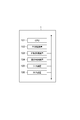
- FIG. 1 It is a figure which shows the structure of an image generation program. It is a block diagram which shows the function structure of the image generation apparatus in 2nd Embodiment. It is a figure which shows the example of the structure of the shape classification table memory
- FIG. 1 is a block diagram showing a functional configuration of an image generation apparatus 1 according to the present embodiment.
- the image generation apparatus 1 uses a still image representing a dish as a processing target image, and synthesizes a composition image that is a moving image in which liquid with motion is represented in a processing target region in which the liquid is mainly represented in the processing target image.
- Output device In the present embodiment, a moving image representing a state in which bubbles are generated in the heated liquid is used as an image for synthesis, and a portion of the cooking image in which ingredients such as vegetables and meat and juice are represented is represented.
- An example in which a moving image showing a state in which bubbles are generated in a region where the juice of a cooking image is represented will be described.
- the image generation apparatus 1 of the present embodiment functionally includes an acquisition unit 11 (acquisition unit), a region information acquisition unit 12 (region information acquisition unit), and a composition image acquisition unit 13 (features).
- Each of the function units 11 to 15 of the image generation apparatus 1 can access storage means such as the image storage unit 21 for synthesis.
- the image generation apparatus 1 can be configured as a server that can communicate with a user terminal via a network.
- the image generation device 1 may be configured as a device such as a smartphone or a personal computer.
- FIG. 2 is a hardware configuration diagram of the image generation apparatus 1.
- the image generation apparatus 1 is physically configured with a CPU 101, a main storage device 102 composed of memories such as a RAM and a ROM, an auxiliary storage device 103 composed of a hard disk, a network card, and the like.
- the computer system includes a communication control device 104, an input device 105 such as a keyboard and mouse, an output device 106 such as a display, and the like.
- the image generation device 1 may not include the input device 105 and the output device 106.
- Each function unit shown in FIG. 1 controls communication under the control of the CPU 101 by reading predetermined computer software (image generation program) on the hardware such as the CPU 101 and the main storage device 102 shown in FIG. This is realized by operating the device 104, the input device 105, and the output device 106, and reading and writing data in the main storage device 102 and the auxiliary storage device 103. Data and databases necessary for processing are stored in the main storage device 102 and the auxiliary storage device 103.
- the compositing image storage unit 21 is a storage unit that stores a compositing image that is a moving image in which a liquid with movement is represented.
- the composition image storage unit 21 stores a plurality of moving images representing how bubbles are generated in the heated liquid as composition images.
- the composition image stored in the composition image storage unit 21 includes various variations in which the type, size, and reproduction speed of the liquid are different.
- the type of liquid include variations such as water, soy sauce, and sauce, and the difference in the viscosity of the liquid is expressed by the difference in these variations.
- the difference in bubble size is expressed by the difference in the size of the image for synthesis.
- the time from the generation of bubbles to the disappearance is expressed by the difference in the reproduction speed of the composite image.
- the size of the foam and the time from occurrence to disappearance depends on the strength of the heating power when the dish is heated.
- the image for synthesis may include a plurality of images obtained by photographing bubbles generated in the heated liquid from different angles. The difference in the height of the generated bubbles is expressed by the difference in the photographing angle.
- the acquisition unit 11 is a part that acquires a processing target image that is an image to be processed.
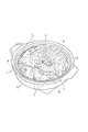
- FIG. 3 is a diagram illustrating an example of the processing target image acquired by the acquisition unit 11. As shown in FIG. 3, in the present embodiment, a dish image representing a pot dish including ingredients such as vegetables and meat and soup is acquired as a processing target image.
- the processing target image of the present embodiment is a still image.
- the region information acquisition unit 12 has a function of accepting designation of a processing target region in the processing target image from the user and a function of specifying the processing target region L based on the received information.
- FIG. 4 is a diagram illustrating an example of accepting designation of a processing target area from a user for the displayed processing target image. As illustrated in FIG. 4, for example, the user can designate a processing target region by inputting a line in the region where the juice to be processed is represented. In FIG. 4, the line input by the user is indicated by a solid line.
- the area information acquisition unit 12 can specify a processing target area by a known image processing technique such as an area divider based on the input line.
- the area information acquisition unit 12 recognizes adjacent pixels whose degree of color difference from a portion where a line is input is equal to or smaller than a predetermined value as the same area, and detects a boundary with a pixel whose color difference exceeds a predetermined value. It can be an area boundary. As illustrated in FIG. 4, the region information acquisition unit 12 acquires a processing target region L based on a line input indicated by a solid line.
- the region information acquisition unit 12 receives an input from the user in order to specify the processing target region L. However, without receiving this input, the region information acquisition unit 12 receives the processing target region L. May be specified. For example, the color of the liquid region is registered in advance, and the region of the color registered by the region information acquisition unit 12 is specified as the processing target region L.
- the processing target area acquired here is not a still image obtained by shooting a moving liquid.
- the image showing the liquid such as the juice in the processing target image is not an image of the liquid that is heated and moves.
- the area information acquisition unit 12 can accept the designation of the reference position F by an input from the user.
- the reference position F can represent the position of the fire source when the dish shown in the dish image is heated.
- the area information acquisition unit 12 can accept designation of an object area that is an area in which ingredients are represented. That is, the area information acquisition unit 12 receives designation of the object area S in which the material is represented based on the input of the line by the user to the portion in which the material is represented.
- a line for designating the object region S is indicated by a one-dot broken line. Processing for the object region S in which the material is represented will be described later as a second embodiment.
- the compositing image acquisition unit 13 acquires a parameter (feature parameter) indicating the feature of the processing target region L that has been designated by the region information acquisition unit 12, and combines it with the processing target region based on the acquired parameter. This is the part for acquiring images. Specifically, first, the compositing image acquisition unit 13 generates a mask indicating the processing target region L in the processing target image.
- FIG. 5 is a diagram schematically illustrating an example of a mask indicating the processing target region L (see FIG. 4) designated by the region information acquisition unit 12. As shown in FIG. 5, eleven processing target areas L are extracted.
- the compositing image acquisition unit 13 calculates and normalizes the distance and the size of each extracted processing target region L from the reference position F, and acquires them as parameters of each processing target region L.
- the parameters acquired here affect the movement of the liquid.
- the distance from the reference position F to the processing target region L is obtained, for example, by obtaining the center of gravity position of the processing target region L and calculating the distance from the reference position F to the center of gravity position.
- the size of the processing target area L is obtained based on the number of pixels of the processing target area L, for example.
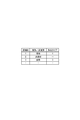
- FIG. 6 is a diagram illustrating parameters of each processing target region L extracted by the synthesis image acquisition unit 13. As shown in FIG. 6, the processing target region L 1 (see FIG. 5) is expressed as a region ID “1”, and parameters such as a distance “far” and a size “large” from the reference position F are associated with each other. ing.
- These parameters indicate the characteristics of the processing target area L, and do not indicate the characteristics of the object represented in the processing target area L.
- the synthesis image is acquired based on the parameters indicating the characteristics of the processing target region L, the object represented in the processing target region L does not need to be a liquid with movement.
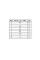
- FIG. 7 is a diagram illustrating an example of a table used for acquiring the attributes of the composition image.
- this table may be preliminarily included in the composition image acquisition unit 13 or may be stored in a storage unit such as the composition image storage unit 21.
- the composition image storage unit 21 refers to the table of FIG. 7 based on parameters such as the distance “far” and the size “medium” from the reference position F of the processing target region L 1 , and the size “100%”.
- the size indicates the ratio of the size to the reference image having a predetermined size
- the reproduction material length indicates the ratio of the reproduction time to the moving image having the predetermined length as the reference. That is, the larger the value of the playback material length, the slower the playback speed.
- the composition image acquisition unit 13 obtains the attributes of the composition image by referring to a table set in advance based on the parameters of the processing target region L. Good. That is, assuming that the size of the processing target area is a (i) and the distance from the reference position is d (i), the size S (i) and the reproduction speed V (i) of the image for synthesis are expressed by the following equation (1). And represented by equation (2). Since the composition image acquisition unit 13 has these equations, it is not necessary to set a table as shown in FIG. 7 in advance.
- a synthesis image acquisition unit 13 also acquires the number of superpositions (composition image information), which is an attribute in the compositing process, indicating the number of superimpositions in the overlay process.
- the synthesis image acquiring unit 13 acquires parameters such superposition number "2".
- the compositing image acquisition unit 13 may further accept a user designation of a parameter (feature parameter) indicating the characteristics of the compositing image.
- the parameter indicating the characteristics of the composition image may indicate the type of liquid such as water, soy sauce, or sauce.
- a moving image showing a state in which bubbles are generated by heating each of these liquids is stored as a composition image including a plurality of variations in size and material length during reproduction. . By specifying these liquid types, the difference in the viscosity of the liquid is expressed.
- the composition image in the present embodiment is a moving image representing a state in which bubbles are generated by heating the liquid, but may be a still image expressing the movement of the liquid.
- the synthesis image acquisition unit 13 acquires a synthesis image corresponding to the acquired attribute of the synthesis image from the synthesis image storage unit 21.
- the synthetic image acquisition unit 13 as synthesis image for synthesizing the processing target area L 1, the size "100%”, acquires a synthesis image having the attributes of the playback time of the material length "150%”.
- the composition image acquisition unit 13 corresponds to the specification, and has a size “100%” and a reproduction material length “150%”. A composite image having attributes is acquired.
- the composition image storage unit 21 stores composition image variations with different sizes and reproduction speeds, and the attributes of these variations are attributes of the composition image (composition image). Information) is acquired by the compositing image acquisition unit 13.
- the size and reproduction speed variations are not stored in the composition image storage unit 21, for example, one composition image is stored in the composition image storage unit 21 for each liquid type. Therefore, an image having a size and a reproduction speed corresponding to the attribute (image information for synthesis) of the image for synthesis acquired with reference to the table shown in FIG. 7 may be generated by the image acquisition unit for synthesis 13.
- the synthesizing unit 14 is a part that synthesizes the synthesis image acquired by the synthesis image acquisition unit 13 with the processing target area. First, a method of arranging the composition image with respect to the processing target area L in the composition process will be described with reference to FIG.
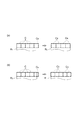
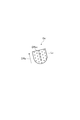
- Combining unit 14 as shown in FIG. 8 (a), the processing target area L to set the rectangular region R L inscribed.
- the synthesizing unit 14 arranges the synthesizing images C in a rectangular area RL in a grid shape.
- the synthesizing unit 14 puts a mask M for preventing the synthesis image C from being displayed on the area other than the processing target area L in the rectangular area RL , The arranged synthesis image C is synthesized with the processing target region L.
- combining unit 14 due to the length of one side of the rectangular region R L does not correspond to an integral multiple of the length of one side of the combined images C, is located at the end of the rectangular region R L sides of the rectangular synthesis image fails to match the sides of the end portion of the rectangular region R L, synthesized by enlarging or reducing the size of all the combined images C arranged in a rectangular region R L was.
- the rectangular region R L of the end portion in the array of synthesis image C E side does not match the side ends of the rectangular region R L, for synthesis If more than half of the area of the image C E does not fit within the R L is, synthesizing unit 14 obtains a composite image C B to expand all the combined images C arranged, it is arranged Composition is performed so that the sides of the composition image coincide with the sides of the rectangular area.
- synthesizing unit 14 obtains a composite image C S by reducing all the combined images C arranged, the array of images to be combined Compositing so that the sides coincide with the sides of the rectangular area.
- the synthesis image C is arranged and synthesized with the processing target area L.
- the synthesis unit 14 adds the synthesis image C to the rectangular area RL inscribed with the processing target area L. It is good also as arrange
- the synthesis unit 14 adds the brightness component of the synthesis image C acquired by the synthesis image acquisition unit 13 to the processing target region L as one of the synthesis processes of the color components of the synthesis image (first process). Synthesis process).
- the composition image C is a moving image having the concept of time, and the pixel value varies with the passage of time. And the movement of the liquid in a moving image is suitably expressed by the fluctuation
- FIG. 10 is a diagram conceptually illustrating the synthesis of the brightness component of the synthesis image with respect to the processing target area.
- Figure A 10 (a) the brightness component V C1 in one of the pixels of the synthesized image C, the corresponding pixel in the process target region L is a time average value V AV and still image luminance component V C1 brightness value V L It is shown.
- the combining unit 14 offsets the lightness component V C1 to the lightness component V C2 so that the time average value V AV matches the lightness value V L , and is used for combining the moving image.
- the image C is combined with the processing target area L.
- the synthesis unit 14 superimposes and synthesizes the synthesis image C on the processing target area L according to the number of superimpositions according to the parameters of the processing target area L ( The second synthesis process) can be performed.
- the number of superimpositions for the superimposition synthesis process is acquired by referring to the table shown in FIG. 7 according to the parameters of the processing target area L by the synthesis image acquisition unit 13, for example.
- the synthesis image C which is a moving image showing the generation and disappearance of bubbles
- the movement of the liquid is expressed more clearly by increasing the number of times of superposition. Therefore, by performing superposition and synthesis of the compositing image C with the number of times of superimposition according to the parameters of the processing target area L, it is possible to express the characteristics of the liquid motion suitable for the attributes of the processing target area L.
- the synthesizing unit 14 determines the brightness component of the image C for synthesis based on the distance in the color space between the color of the image C for synthesis acquired by the image acquisition unit 13 for synthesis and the color of the processing target region L. Either one of the synthesis process to be added to L and the synthesis process to superimpose the synthesis image C on the processing target area L may be performed.
- the synthesis unit 14 superimposes the average value of the pixel values indicating the color of the synthesis image C acquired by the synthesis image acquisition unit 13 and the synthesis image C in the processing target region L. The distance in the color space from the average value of the pixel values indicating the color in the area to be obtained is obtained. Then, when the obtained distance is equal to or less than the predetermined value, the synthesizing unit 14 performs a synthesizing process for adding the brightness component of the synthesizing image C to the processing target region L. On the other hand, when the obtained distance exceeds a predetermined value, the synthesizing unit 14 performs a synthesizing process in which the synthesis image C is superimposed and synthesized on the processing target region L. Thereby, in order to more suitably represent the movement of the liquid in the processing target region L, it is possible to select a more appropriate synthesis process.
- the composition unit 14 may perform blurring on the processing target region L before compositing the composition image C with the processing target region L.
- the synthesis unit 14 may perform so-called blur processing on the image of the processing target region L.
- the synthesizing unit 14 may calculate the average of the pixel values representing the colors of the pixels of the image in the processing target area L, and use the calculated average value as the pixel value of each pixel of the image of the processing target area L. . By these processes, a more natural composite image can be obtained.
- the output unit 15 is a part that outputs a processing target image in which the synthesis image C is synthesized by the synthesis unit 14.
- FIG. 11 is a diagram illustrating a part of the processing target image in which the composition image C is combined with the processing target region L.
- the output unit 15 outputs an image in which a synthesis image C representing a state in which bubbles are generated is synthesized in the processing target region L in the processing target image shown in FIG. 3.
- the dish image shown in the base processing target image represents a dish in a heated state. It doesn't need to be a thing. Accordingly, it is possible to output a cooking image in which ingredients that are not in a heated state and appear to be delicious and liquids such as juice that appear to be delicious because of movement are output.
- one or more same compositing images C are arranged in one processing target area L and synthesized.
- the image generation apparatus 1 when a synthesis image is synthesized with one processing target region L, an exception process is performed in which a synthesis image corresponding to a synthesis position is selected and synthesized. Also good. A specific example will be described below.
- the compositing image acquisition unit 13 obtains the processing target area L from the reference position F when acquiring the compositing image. It is also possible to obtain a compositing image in which the reproduction speed and / or size is set according to the distance to the position where the compositing image is placed.
- the composition image acquisition unit 13 performs one composition from the reference position F after the provisional placement of the composition image C with respect to the processing target region L by the composition unit 14.
- the attribute of the compositing image according to the distance to the arrangement position of the image C is acquired with reference to a table (see FIG. 7) in which the distance from the reference position is associated with the attribute of the compositing image.
- the synthesis image acquisition unit 13 acquires a synthesis image corresponding to the acquired attribute, and the synthesis unit 14 combines the reacquired synthesis image with the arrangement position.
- the synthesizing unit 14 uses the reference position F in the processing target image for the synthesis in the processing target area L.
- the composition image may be superimposed and synthesized on the processing target area according to the number of times of superimposition according to the distance to the position where the image is arranged.
- the composition unit 14 after performing the provisional arrangement of the composition image C with respect to the processing target region L by the composition unit 14, the composition unit 14 performs the number of times of superimposition according to the distance from the reference position F to the arrangement position of one composition image C. Is obtained with reference to a table (see FIG. 7) in which the distance from the reference position is associated with the number of times of overlay in the overlay process. Then, the combining unit 14 combines the combining image with the arrangement position according to the acquired number of times of superimposition.
- the distance from the reference position F assumed as the fire source position in the dish image By selecting and composing the compositing image according to the above, a suitable compositing image in which the liquid movement such as generation of bubbles is not unnatural can be obtained.
- the ingredients in the processing target region L are considered in view of the fact that the generation of bubbles is slower in the portion near the ingredients of the juice than in the portion that is more than a certain distance from the ingredients.
- Predetermined weighting can be applied to the image for synthesis synthesized in the area near the material. Specifically, after the provisional placement of the compositing image C with respect to the processing target region L by the compositing unit 14, the compositing image acquisition unit 13 determines the position at which the compositing image is placed in the processing target region L.
- a synthesis image in which a predetermined weight is added to the reproduction speed and / or size of the synthesis image is acquired.
- the composition image acquisition unit 13 acquires from the composition image storage unit 21 a composition image having a reproduction material length larger than that of the temporarily arranged composition image. Then, the synthesizing unit 14 synthesizes the re-acquired synthesis image with the arrangement position.
- the synthesizing unit 14 may add a predetermined weight to the number of times of superimposing when synthesizing the synthesis image. Specifically, after the provisional placement of the compositing image C with respect to the processing target region L by the compositing unit 14, the compositing unit 14 is configured for compositing disposed within a predetermined distance from the edge of the processing target region L. The number of superimpositions in overlay composition with a predetermined amount of weight added to the image is set, and the composition image is composed according to the set number of superimpositions. As described above, since an image for synthesis is synthesized with an appropriate weight applied to an area in the vicinity of the material of the processing target area L, an image in which the movement of the liquid at the edge of the processing target area is appropriately expressed is obtained. It is done.
- FIG. 12 is a flowchart showing an example of processing contents of the image generation method in the image generation apparatus 1 shown in FIG.
- the acquisition unit 11 acquires a processing target image that is a still image to be processed (S1).
- the region information acquisition unit 12 accepts selection of an image composition mode from the user (S2). That is, the selection of the processing method of the lightness assignment algorithm (first combining process) or the overlay combining (second combining process) is accepted.
- the selection of the synthesis mode is explicitly accepted from the user, but the synthesis mode may be automatically selected by the synthesis unit 14.
- the region information acquisition unit 12 accepts designation of a processing target region in the processing target image (S3).
- the compositing image acquisition unit 13 generates a mask indicating the processing target area L in the processing target image (S4).
- the composition image acquisition unit 13 calculates and acquires parameters such as the distance and size of each extracted processing target region L from the reference position F (S5).
- the compositing image acquisition unit 13 may further accept a user designation of a parameter indicating the characteristics of the compositing image (S6).
- the compositing image acquisition unit 13 classifies the processing target area based on the parameters, provisionally determines a compositing image corresponding to the parameters, and acquires it from the compositing image storage unit 21 (S7).
- the composition image acquisition unit 13 also acquires the number of times of superimposition according to the parameters of the processing target region.
- step S8 If overlay composition is selected as the composition mode, the processing procedure proceeds to step S8.
- step S12 On the other hand, when the synthesis by the brightness imparting algorithm is selected as the synthesis mode, the processing procedure proceeds to step S12.
- step S8 the synthesizing unit 14 temporarily arranges the synthesis image acquired in step S7 to synthesize it with the processing target area (S8).
- the synthesizing unit 14 also temporarily determines the number of superpositions acquired in step S7. Here, it is determined whether or not there is a region where exception processing is to be performed (S9).
- One of the exception processes is that when there is a processing target region having a size larger than a predetermined size with respect to the size of the processing target image, the reproduction speed and size according to the distance from the reference position F in the processing target image are set. This is a process of synthesizing the composition image.
- the other exceptional process is a process for applying a predetermined weight to the synthesis image synthesized at the edge of the processing target area.
- the composition image acquisition unit 13 and the composition unit 14 perform exception processing (S10).
- the synthesizing unit 14 then performs a synthesizing process that overlays the synthesizing image on the processing target area including the exception process in step S10 (S11).
- step S12 the composition unit 14 temporarily arranges the composition image acquired in step S7 in order to synthesize the image for processing (S12).
- step S9 it is determined whether there is a region where exception processing is to be performed (S13). If it is determined that there is a region where exception processing is to be performed, the composition image acquisition unit 13 and the composition unit 14 perform exception processing (S14). Then, the synthesizing unit 14 performs the synthesizing process for the synthesizing image with respect to the processing target area by the brightness providing algorithm including the exception process in step S14 (S15).
- step S16 based on an instruction from the user or automatically by the system, adjustment processing such as color tone may be performed on the image obtained by the synthesis processing (S16).
- step S16 a process for adding sound to the image can be performed.
- the output part 15 outputs the process target image by which the image for a synthesis
- the image generation program P1 includes a main module m10, an acquisition module m11, an area information acquisition module m12, a composition image acquisition module m13, a composition module m14, and an output module m15.
- the main module m10 is a part that comprehensively controls the image generation process.
- the functions realized by executing the acquisition module m11, the region information acquisition module m12, the composition image acquisition module m13, the composition module m14, and the output module m15 are the acquisition unit 11 of the image generation apparatus 1 shown in FIG.
- the functions of the area information acquisition unit 12, the composition image acquisition unit 13, the synthesis unit 14, and the output unit 15 are the same.
- the image generation program P1 is provided by a storage medium 1D such as a CD-ROM, a DVD, or a ROM, or a semiconductor memory, for example.
- the image generation program P1 may be provided via a communication network as a computer data signal superimposed on a carrier wave.
- the processing target area L is received in the processing target image and associated with the parameter indicating the characteristics of the processing target area L.
- the composition image acquired based on the attribute of the composition image is combined with the processing target region L.
- the composition image C showing the liquid with movement is synthesized with the processing target area that is a part of the processing target image including the case where the image is a still image. It is possible to synthesize an image of a liquid that accompanies movement in an area in which an image of a stationary liquid is represented.
- FIG. 14 is a block diagram illustrating a functional configuration of an image generation device 1A (moving image generation device) according to the second embodiment.
- the image generating apparatus 1A uses the image representing the dish as the processing target image, acquires region information for specifying the object region in which the object is represented in the processing target image, and displays the moving image displayed as if the object is vibrating Is a device that generates
- a moving image is generated that shows a state in which ingredients are vibrated by heating, with an area representing the ingredients in the cooking image representing ingredients such as vegetables and meat and a juice being represented as an object area.
- a still image representing a dish is used as the processing target image.
- a cooking image including a moving image of ingredients with little movement may be used as the processing target image.
- the image generation device 1A has an acquisition unit 11 (image acquisition unit), a region information acquisition unit 12A (region information acquisition unit), a synthesis image acquisition unit 13, and a synthesis unit that the image generation device 1 has. 14, an output unit 15 (output unit), a setting unit 16 (setting unit), and a generation unit 17 (generation unit).
- the setting unit 16 can access storage means such as the shape classification table storage unit 22.
- the acquisition unit 11 is a part that acquires a processing target image that is an image to be processed. As shown in the first embodiment, the acquisition unit 11 acquires a dish image representing a pot dish including ingredients such as vegetables and meat and soup as shown in FIG.
- the area information acquisition unit 12A is a part that acquires area information for specifying an object area in which an object to be processed is represented in the processing target image.
- the area information acquisition unit 12A accepts designation of an object area by a user, and specifies an object area based on the accepted information. The reception of the designation of the object area will be described with reference to FIG.
- the area information acquisition unit 12A can accept a process target area and can also accept designation of an object area that is an area in which ingredients are represented.
- the region information acquisition unit 12A accepts designation of the object region S in which the material is represented based on the input of a line by the user to the portion in which the material is represented. In FIG. 4, a line for designating the object region S is indicated by a one-dot broken line.
- the area information acquisition unit 12A may acquire, as area information, an object area specified by a known image processing technique such as area division using image color information.
- the setting unit 16 is a part for setting a fixed control point, a vibration control point, and a vibration direction in the object based on the shape of the object region S received by the region information acquisition unit 12A.
- the shape of the object region S is obtained by designation by the user or known image processing.
- the fixed control point and the vibration control point respectively indicate a portion where the position is fixed and a portion which is vibrated with respect to the fixed control point when generating a moving image displayed as if the object is vibrating.
- the vibration direction indicates a direction in which the vibration control point is vibrated with respect to the fixed control point.
- the setting unit 16 makes these settings with reference to the shape classification table storage unit 22.
- the setting unit 16 receives designation of one of the deformation and non-deformation attributes for the object from the user, and when the deformation attribute is received, the setting unit 16 fixes the fixed control point, the vibration control point, and the vibration direction with respect to the object area. Set.
- the shape classification table storage unit 22 is a storage unit that stores an object shape, a fixed control point, a vibration control point, and a vibration direction in association with each other.
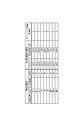
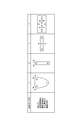
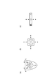
- FIG. 15 is a diagram illustrating a configuration of the shape classification table storage unit 22 and an example of stored data. As illustrated in FIG. 15, the shape classification table storage unit 22 stores various object shapes, fixed control points, vibration control points, and vibration directions in association with each shape type ID. In the table of FIG. 15, fixed control points are indicated by x, vibration control points are indicated by circles, and vibration directions are indicated by arrows.
- FIG. 16 is a diagram illustrating an example of the object region S and its shape R received by the region information acquisition unit 12A.
- the attribute of the object such as deformation or non-deformation and the shape of the object area S are specified by the user.
- FIG. 17 is a diagram showing a table that stores the deformation or non-deformation attributes and shape types designated for each object region S.
- the area information acquisition unit 12A accepts the designation of the object area S 1.
- the setting unit 16 accepts an attribute designation of “deformation” from the user and the shape table (FIG. 15) based on the shape R 1 of the object region S 1 because the leaf vegetable is an object whose shape is deformed when heated.
- the specification of the shape type ID “1” among the shape types stored in is received.
- the setting unit 16 stores the attribute “deformation” and the shape type “1” in the table shown in FIG. 17 in association with the area ID “1” of the object area S 1 .
- the setting unit 16 performs fixed control points, vibration control on the object region S 1 according to the fixed control points, vibration control points, and vibration directions associated with the shape of the shape type ID “1” in the shape classification table. Set point and vibration direction.
- the area information acquisition unit 12A accepts the designation of the object area S 2.
- the setting unit 16 receives an attribute designation of “non-deformation” from the user because Shiitake is an object whose shape does not deform during heating.
- the setting unit 16 stores the attribute “non-deformation” in association with the area ID “2” of the object area S 2 in the table illustrated in FIG.
- the setting unit 16 the attribute of the object area S 2 because it is non-deformable, fixed control points, does not set the vibration control points and the vibration direction.
- the area information acquisition unit 12A receives the designation of the object area S 3.
- the setting unit 16 accepts an attribute designation of “deformation” from the user and the shape table (FIG. 15) based on the shape R 3 of the object region S 3 because the long leek is an object whose shape is deformed when heated.
- the designation of the shape type ID “3” among the stored shape types is accepted.
- the setting unit 16 the table shown in FIG. 17, in association with the area ID of the object area S 3 "3", and stores the attribute "deformation” and feature type "3” .
- the setting unit 16 fixed control points associated with the shape of the feature type ID "3" in the shape classification table according to the vibration control points and the vibration direction, a fixed control point for the object area S 3, vibration control Set point and vibration direction.
- FIG. 18 is a diagram illustrating an example of setting a rectangular area for setting a fixed control point, a vibration control point, and a vibration direction in the object area S.
- 18 (a) is a diagram showing an object area S 0 received by the area information obtaining unit 12A.
- the setting unit 16 calculates the longitudinal direction of the object region S 0 by a method such as principal component analysis, and calculates the short direction orthogonal to the longitudinal direction.
- . 18 (b) is a diagram showing an object region longitudinal direction (X-axis direction) calculated for S 0 and lateral direction (Y axis direction).
- the setting unit 16 as shown in FIG.
- the object area S 0 has sides parallel to the respective longitudinal and lateral direction to set the rectangular region R 0 inscribed.
- the setting unit 16 refers to the shape classification table (see FIG. 15) and sets a fixed control point or the like corresponding to the selected shape type for the rectangular region R0 .
- FIG. 19 is a diagram schematically showing the state of vibration for each object region S (see FIG. 16) received by the region information acquisition unit 12A.
- the generation unit 17 sets the magnitude of vibration at the vibration control point according to, for example, the size of the object area. Specifically, assuming that the size of the object region S is associated with the magnitude of vibration in advance, the generation unit 17 acquires the size of the object region S based on, for example, the number of pixels, The magnitude of vibration corresponding to the size of the acquired object area S can be set for the object area S. For example, the magnitude of the vibration may be set to be smaller as the size of the object area is larger.
- the generation unit 17 sets the processing target region at a nearby position within a predetermined distance from the object region S.
- the magnitude of the vibration of the object may be controlled according to the attribute of the synthesized image for synthesis.
- the generation unit 17 generates a moving image in which the magnitude of the vibration of the object region S increases as the size of the composition image to be combined near the object region S increases or the playback speed increases. It is good to do.
- the output unit 15 outputs the processing target image generated by the generation unit 17 and synthesized with the moving image displayed as if the object region S vibrates. Specifically, the output unit 15 displays a processing target image in which moving images displayed such that each of the object regions S specified in FIG. 4 is vibrating as described with reference to FIG. 19 are combined. Output.
- FIG. 20 is a flowchart illustrating an example of the processing content of the image generation method in the image generation apparatus 1A illustrated in FIG.
- the acquisition unit 11 acquires a processing target image that is a still image to be processed (S31).
- the area information acquisition unit 12A receives, for example, designation of the object area S in which the ingredients in the dish image are represented (S32).
- the region information acquisition unit 12A accepts designation of an attribute such as deformation or non-deformation and a shape type.
- a mask indicating the object region S in the processing target image is generated (S33).
- step S35 If “deformation” is set as the attribute of the object area S, the processing procedure proceeds to step S34.
- step S34 the setting unit 16 sets the magnitude of vibration based on the size of the object area S and the attribute of the bubble image (image for synthesis) synthesized around the object area S (S34).
- step S35 the setting unit 16 sets a fixed control point, a vibration control point, and a vibration direction based on the shape type of the object region S (S35). Further, the setting unit 16 sets the magnitude of vibration based on the size of the object area S and the attribute of the bubble image (image for synthesis) synthesized around the object area S (S36).
- the generation unit 17 generates a moving image displayed as if the object region S is vibrating, and synthesizes the moving image with the processing target image (S37). Then, the output unit 15 outputs a composite image in which the object region S displayed so as to vibrate is combined (S38).
- the image generation program P1 includes a setting module for realizing the function of the setting unit 16 and a generation module for realizing the function of the generation unit 17.
- an image generation program for causing the computer to function as the image generation apparatus 1A is configured.
- the area information for specifying the object area S in the processing target image is acquired, and the fixed control set in the object area S is acquired.
- a moving image is generated that is displayed as if the object is vibrating according to the point, the vibration control point, and the vibration direction.
- a hamburger is baked by synthesizing an image for synthesis representing a state in which bubbles are generated in a region where the oil around the hamburger is represented with respect to a photograph of the hamburger that has been cooled. It can be applied to express a state in the middle or immediately after baking. In addition, the present invention is applied to expressing a state immediately after being baked by synthesizing an image for synthesis representing a state where bubbles are generated in a region of the surface of the fish with a photograph of a chilled grilled fish. it can.
- the processing target area may be any area as long as it is designated by the user, and is not limited to the area where the liquid is represented.
- the image generation apparatuses 1 and 1A of the present embodiment shown in FIG. 1 and FIG. 14 partially synthesize or superimpose another image on the target image, or superimpose or partially replace it. It is an apparatus which produces
- the composition image storage unit 21 may store a plurality of still images as a composition image in addition to the moving image showing the liquid with movement.
- the plurality of still images are, for example, a plurality of still images obtained by photographing a liquid with movement at predetermined time intervals. More specifically, the plurality of still images are, for example, a plurality of images that represent in stages how bubbles are generated in the heated liquid.
- the area information acquisition unit 12 (area specifying means) specifies one or a plurality of areas where the target image is processed.
- the target image is a processing target image acquired by the acquisition unit 11.
- the region information acquisition unit 12 receives designation of the processing target region in the processing target image from the user (see FIG. 4), the region information acquisition unit 12 specifies the processing target region L based on the received information.
- the processing target area L is an area to be processed (see, for example, FIG. 5).
- the area information acquisition unit 12 may constitute means (processing contents specifying means) for specifying processing contents in an area specified as a processing target area.
- the processing content may be designated based on whether the processing target area is an area representing a liquid or an object area representing an object.
- the area information acquisition unit 12 may have a function of accepting specification of processing content from the user.
- the synthesizing image acquisition unit 13 designates another image for processing the designated area of the target image. That is, the compositing image acquisition unit 13 designates a compositing image for processing the processing target area of the processing target image. As described in the first embodiment, the compositing image acquisition unit 13 acquires a compositing image from the compositing image storage unit 21 according to the parameters of the processing target region L, for example.
- the synthesizing unit 14 (generating means, image generating means) performs processing based on the specified processing content on the processing target image to generate an operation image. And the synthetic
- the output unit 15 outputs the moving image generated by the combining unit 14.
- the processing content of the synthesis unit 14 will be specifically described below.
- the synthesizing unit 14 processes the processing target image with each still image of the synthesis image to generate a plurality of motion images. Then, the synthesizing unit 14 generates a moving image by combining a plurality of motion images so that they can be displayed in time series.
- the composition image is a plurality of still images that express in stages how the liquid is heated and bubbles are generated. May be.
- a plurality of still images include, for example, the state of liquid before bubbles are generated, the state of the initial stage of bubble generation, the state of the stage in the middle of bubble generation, and the bubbles to the maximum size. It can be assumed that a still image showing a state of becoming a bubble, a state where a bubble bursts, or the like is included.
- the synthesizing unit 14 synthesizes each still image representing a state where bubbles are generated in an area where the liquid in the cooking image that is the processing target image is represented, and generates an operation image. And the synthetic
- the image to be processed is an image of a person's face with eyes open
- the composition image is an image representing an eye portion, and the first image with the eyes closed. It may be a still image and a second still image with half-open eyes.
- the synthesizing unit 14 generates a first motion image obtained by synthesizing the first still image with the eye region of the processing target image and a second motion image obtained by synthesizing the second still image.
- combination part 14 produces
- the synthesizing unit 14 generates a plurality of motion images by processing the image to be processed using images of scenes in a moving image that is a synthesis image. Then, the synthesizing unit 14 generates a moving image by combining a plurality of motion images so that they can be displayed in time series.
- the processing target image is a cooking image as shown in FIG. 3, for example, the composition image may be a moving image expressing a state in which bubbles are generated by heating the liquid.
- the synthesizing unit 14 images each scene in the moving image representing a state in which bubbles are generated in the region where the liquid in the cooking image that is the processing target image is represented (among the plurality of frames constituting the moving image). One frame) is synthesized to generate motion images.
- combination part 14 produces
- the synthesizing unit 14 generates a moving image by arranging a plurality of moving images in which a display order is set according to a frame order constituting a moving image expressing a state in which bubbles are generated according to the display order. .
- the synthesizing unit 14 processes the images of the scenes of the processing target image with the images of the scenes of the synthesis image to generate a plurality of motion images. Then, the synthesizing unit 14 generates a moving image by combining a plurality of motion images so that they can be displayed in time series.
- the composition image is a moving image that represents a state in which bubbles are generated by heating the liquid.
- the synthesizing unit 14 adds bubbles to the image of each scene of the region where the liquid is represented in the cooking image that is the processing target image (the region where the liquid is represented in one frame among the plurality of frames constituting the cooking image).
- Each of the scene images (one frame among a plurality of frames constituting the moving image) in the moving image representing the appearance of the moving image is synthesized to generate an operation image.
- combination part 14 produces
- the movement represented in the processing target image can be more emphasized.
- the area information acquisition unit 12 specifies an operation direction in an area where the processing target image is to be processed. Specifically, the area information acquisition unit 12 accepts designation of an operation direction based on, for example, an input by a user.
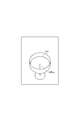
- FIG. 21 is a diagram illustrating an example of the processing target image. 21 is shown sparkling wine poured into a glass is sparkling wine is represented area is designated as an area L A subjected to machining.
- the area information acquisition unit 12 receives the designation of the operation direction DR A1 based on the user input. For example, the user designates a vertical upward direction in the processing target image as the operation direction DR A1 .
- FIG. 22 is a diagram illustrating an example of a composition image. In the example of FIG.
- the composition image represents a state where bubbles move.
- the movement direction of the bubbles is set as the operation direction DR B1 .
- the synthesis image acquisition unit 13 may detect the movement direction of the feature point in the synthesis image and set the movement direction as the movement direction DR B1 .
- FIG. 23 is a diagram illustrating an example of the motion image generated by the synthesis unit 14.
- the combining unit 14 generates the operation direction DR A1 in the region L A subjected to processing, the operation image G A1 giving the process so that the operating direction DR B1 in combined images coincide with each other To do. That is, the synthesizing unit 14 rotates and synthesizes the synthesis image with respect to the processing target image so that the motion direction DR A1 matches the motion direction DR B1 .
- FIG. 24 is a diagram illustrating another example of a composition image.
- operating direction DR B2 is set.
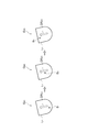
- Combining unit 14 the operation direction DR A1 in the region L A subjected to processing, and the operation direction DR B2 in the combined image to generate an operation image G B1 ⁇ G B3 giving the process to match each other.
- the synthesizing unit 14 displays each image B 1 to B 3 representing a state in which the image B 0 representing bubbles moves in a stepwise manner along the motion direction DR B2.
- the example of expressing the movement of bubbles in the image of sparkling wine poured into the glass has been described.
- the expression can be applied to a thing with a certain directionality in the movement.
- the present invention can be applied to generation of a moving image representing smoke generated from a chimney.
- the processing target image and / or the composition image of the present embodiment may be configured by three-dimensional image data. That is, a three-dimensional model expressed in the world coordinate system is used as data for displaying the processing target image. In addition, a three-dimensional model expressed in a local coordinate system is used as data for displaying an image for synthesis. Based on these three-dimensional image data, what is projected onto the two-dimensional image is output and displayed as an image. With reference to FIGS. 26 to 27, an example in which the image to be processed and / or the image for synthesis is composed of three-dimensional image data will be described.
- FIG. 26 is a diagram illustrating an example of the processing target image displayed based on the three-dimensional image data.
- the processing target image shown in FIG. 26, there is shown sparkling wine poured into a glass is, sparkling wine is represented area is designated as an area L A2 subjected to machining.
- the region information acquisition unit 12 accepts the designation as the operation direction DR A2 in the vertically upward direction from the bottom of the glass to the liquid level.
- the motion direction DR A2 in the processing target image is expressed by a vector described in the world coordinate system.
- three-dimensional image data representing bubbles is used as an image for synthesis.
- the motion direction which is the direction of movement of the bubbles in this composite image, is expressed by a vector described in the local coordinate system.
- the synthesizing unit 14 generates images B 11 to B 13 representing how the bubbles move stepwise along the operation direction DR A2 based on the three-dimensional image data representing the bubbles,
- the generated images B 11 to B 13 are respectively combined with the region L A2 to be processed to generate operation images G B11 to G B13 .
- the local coordinates are set in a vector representing the motion direction DR A2 in the world coordinate system so that the motion direction specified by the user for the processing target image matches the motion direction of the bubbles in the processing target image.
- the three-dimensional model of the image for synthesis is rotated and synthesized with the image to be processed so that the vectors representing the direction of bubble movement in the system match.
- the composition image storage unit 21 may store a plurality of still images as a composition image in addition to the moving image showing the liquid with movement.
- the plurality of still images are, for example, a plurality of still images obtained by photographing a liquid with movement at predetermined time intervals. More specifically, the plurality of still images are, for example, a plurality of images that represent in stages how bubbles are generated in the heated liquid.
- the area information acquisition unit 12A designates one or a plurality of areas where the target image is processed.
- the target image is a processing target image acquired by the acquisition unit 11.
- the region information acquisition unit 12A receives designation of an object region in the processing target image from the user (see FIG. 4), the region information acquisition unit 12A specifies the object region as a processing target region to be processed based on the received information.
- the region information acquisition unit 12A may constitute means (processing content specifying means) for specifying the processing content in the region specified as the processing target region.
- the processing content may be designated based on whether the processing target area is an area representing a liquid or an object area representing an object.
- the area information acquisition unit 12A may have a function of accepting specification of processing content from the user.
- the synthesizing image acquisition unit 13 designates another image for processing the designated area of the target image. That is, the compositing image acquisition unit 13 designates a compositing image for processing the processing target area of the processing target image.
- the compositing image acquisition unit 13 may extract an image of an object specified as a processing target area from the processing target image as a compositing image, for example.
- the generation unit 17 (generation unit, image generation unit) performs processing based on the specified processing content on the processing target image to generate an operation image. And the synthetic
- the output unit 15 outputs the moving image generated by the combining unit 14.
- the processing content of the synthesis unit 14 will be specifically described below.
- the generation unit 17 generates a plurality of motion images by processing the processing target image with the synthesis image. Then, the generation unit 17 generates a moving image by combining the processing target image itself and the generated operation image so that they can be displayed in time series.
- the composition image is, for example, an image of an object represented in the object area specified based on the user's designation.
- the image of the object that is the composition image can be extracted from the processing target image.
- the generation unit 17 makes the object vibrate with respect to the original image of the object based on the set fixed control point, vibration control point, and vibration direction. A visible image is generated as an action image. Then, the generation unit 17 generates a moving image by combining the object image itself in the processing target image and the generated operation image so that they can be displayed in time series.
- the generation unit 17 generates one or a plurality of motion images representing a state in which the processing target image gradually changes to an image after the processing target image is changed with time. This example will be specifically described with reference to FIG.
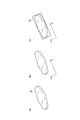
- the generation unit 17 generates an image of the object after change based on the image of the object extracted from the processing target image. For example, when an object region as shown in FIG. 16C is designated as a processing target region and extracted as a synthesis image, the generation unit 17 creates the object region as shown in FIG. Operation images O 1 to O 3 representing changes with time are generated. For example, for a bar-shaped object, an action image that is gradually curved is generated. Thereby, for example, it can be shown that the long onion is soft. Then, the generation unit 17 combines the motion images O 1 to O 3 with the processing target area of the processing target image to generate a moving image. Thereby, the image showing a time-dependent change of ingredients etc. in a cooking image can be obtained easily.
- the generation unit 17 generates a plurality of motion images that gradually darken the baked color.
- the generation unit 17 generates one or a plurality of motion images that represent the motions and temporal changes based on the first and second synthesis images. This example will be specifically described with reference to FIG.
- the generation unit 17 For example, based on the image of the object extracted from the image to be processed, the generation unit 17 generates an image representing the movement and change with time of the object. For example, when an object region as shown in FIG. 16C is designated as a processing target region and extracted as a synthesis image, the generation unit 17 selects the object region as shown in FIG. Motion images O 1A and O 1B forming a pair indicating the motion are generated. The motion images O 1A and O 1B are alternately displayed in time series, thereby expressing the motion of the object.
- the generation unit 17 generates motion images O 2A and O 3A representing changes with time of the object represented in the motion image O 1A . Further, the generation unit 17 represents the vibrations of the objects represented in the motion images O 2A and O 3A , and generates motion images O 2B and O 3B that are paired with these motion images, respectively. Then, the generation unit 17 combines the motion images O 1A , O 1B , O 2A , O 2B , O 3A , and O 3B with the processing target area of the processing target image to generate a moving image. Thereby, the image showing operation
- each function of the image generation apparatuses 1 and 1A described in the other embodiments is realized by executing an image generation program including functional modules for realizing each function by a computer, and the computer is the image generation apparatus. 1, 1A.
- a synthesis image acquisition means for acquiring a synthesis image based on the synthesis image information stored in association with the feature parameter;
- Synthesizing means for synthesizing the synthesis image acquired by the synthesis image acquiring means with the processing target region;
- Output means for outputting a processing target image obtained by synthesizing the synthesis image by the synthesis means;
- (Clause 12) An image generation method executed by a computer, An acquisition step of acquiring a processing target image that is a processing target image; An area information acquisition step for acquiring area information for specifying a processing target area in the processing target image; A feature acquisition step for indicating a feature of the processing target region specified by the region information acquired in the region information acquisition step, and acquiring a feature parameter that affects the movement of the liquid; The processing target area acquired by referring to the storage means that stores the characteristic parameter that affects the movement of the liquid in association with the image information for synthesis for acquiring the image for synthesis in which the liquid accompanying the movement is represented.
- a compositing image acquisition step for acquiring a compositing image based on the compositing image information stored in association with the feature parameter;
- An output hand step for outputting a processing target image obtained by synthesizing the synthesis image in the synthesis step;
- An image generation method comprising:
- a composite image acquisition function for acquiring a composite image based on the composite image information stored in association with the feature parameter;
- a synthesis function for synthesizing the synthesis image acquired by the synthesis image acquisition function into the processing target region;
- An output function for outputting an image to be processed in which a synthesis image is synthesized by the synthesis function;
- An image generation program that realizes
- the region information for specifying the processing target region in the processing target image is acquired, and the composite image acquired based on the composite image information associated with the feature parameter indicating the feature of the processing target region is processed.
- Composite to the target area Composite to the target area.
- the composition image in which the liquid accompanied by the movement is synthesized with the processing target area that is a part of the processing target image including the case of the still image.
- the still image of the dish that is not heated An image of a liquid with movement can be synthesized in the area where the liquid in a stationary state is represented. Therefore, it is possible to obtain a cooking image in which ingredients that are not in a heated state and appear to be delicious and liquids that appear to be delicious because of movement are displayed.
- the image for synthesis is acquired based on the characteristic parameter that affects the liquid movement, it is not always necessary that the characteristic of the liquid movement is represented in the processing target region.
- an appropriate composition image based on the characteristics of the processing target area is acquired by the computer based only on easy input such as designation of the processing target area, it is easy to create a cooking image in which both ingredients and liquids look delicious. Can get to.
- the compositing image acquisition means includes Refer to the storage means for storing the feature parameter in association with at least one of the reproduction speed and size of the image for synthesis and the number of times of superimposing when the image for synthesis is combined with the processing target region, Obtaining the compositing image according to the feature parameter of the processing target area whose designation is received by the information obtaining means; Item 2.
- the image generation device according to Item 1.
- the reproduction speed and size in the composition image and the number of times of superimposition when the composition image is combined with the processing target area are, for example, the size of the liquid portion in the dish shown in the dish image.
- Features of liquid movement such as the distance from the source of the area, can be represented.
- the synthesis image having the reproduction speed and size according to the characteristic parameter of the processing target area and the number of superimpositions is acquired, an appropriate synthesis image is selected for the designated processing target area. .
- the feature parameter of the processing target area includes a position specified by a user in the processing target image or a distance from the predetermined position set in advance to the processing target area, the size of the processing target area, and the processing target area. Including at least one of the parameters indicating the viscosity of the liquid represented in Item 3.
- the image generation device according to Item 2.
- the parameters such as the distance from the predetermined position to the processing target area and the size of the processing target area, the parameter indicating the viscosity of the liquid expressed in the processing target area,
- the distance from the fire source in cooking, the size of the liquid portion in the cooking shown in the cooking image, and the viscosity of the liquid portion can be included in the parameters.
- the synthesis means includes A first synthesis process for synthesizing the brightness component of the synthesis image acquired by the synthesis image acquisition unit with the processing target area; or In accordance with the number of times of superimposition according to the characteristic parameter acquired by the acquisition unit, one of the second synthesis processes for superimposing and synthesizing the synthesis image on the processing target area is performed.
- Item 4 The image generating device according to Item 2 or 3.
- the movement of the liquid in the moving image is suitably expressed by the fluctuation of the brightness component. Further, by superimposing a composition image, which is a moving image showing a liquid accompanied by a movement, on the processing target area an appropriate number of times, the movement of the liquid is suitably represented. According to this aspect, the first synthesis process for synthesizing the brightness component of the synthesis image to the processing target region or the second synthesis process for superimposing the synthesis image at an appropriate number of times is performed.
- the movement of the liquid is preferably represented in the region.
- the synthesizing unit is configured to perform the first synthesizing process and the second synthesizing process based on a distance in a color space between the color of the synthesis image acquired by the synthesis image acquiring unit and the color of the processing target area. Do either one, The image generation apparatus according to claim 4.
- a more appropriate synthesis process is selected in order to more suitably represent the movement of the liquid in the processing target region, out of the first and second synthesis processes.
- the compositing image acquisition means stores the memory according to a distance from a position specified by a user in the processing target image or a predetermined position set in advance to a position where the compositing image is arranged in the processing target region.
- the synthesizing unit refers to the storage unit according to a distance from a position specified by the user in the processing target image or a predetermined position set in advance to a position where the synthesis image is arranged in the processing target region.
- the composition image is superimposed and synthesized on the processing target area.
- Item 6 The image generating device according to Item 4 or 5.
- the size of the processing target area is larger than a predetermined size.
- the synthesis image acquisition means acquires a synthesis image in which a predetermined weight is added to the reproduction speed and / or size of the synthesis image, or
- the synthesizing unit adds a predetermined weight to the number of times of superimposing when synthesizing the synthesis image.
- Item 7. The image generating device according to any one of Items 4 to 6.
- the edge of the processing target area corresponds to, for example, a portion in the vicinity of the ingredients in the area where the liquid of the cooking image is represented.
- the portion near the ingredients of the cooking liquid being heated is different from the portion not near the ingredients.
- the reproduction speed and / or size of the composition image arranged at the edge of the processing target area is weighted, or the number of superimposing times when the composition image is superimposed is weighted.
- the synthesizing unit arranges one or more compositing images acquired by the synthesizing image acquisition unit in a rectangular region inscribed by the processing target region, and in the region other than the processing target region in the rectangular region, A mask is applied so that the synthesis image is not displayed, and the synthesis image is synthesized with the processing target area.
- Item 8 The image generating device according to any one of Items 1 to 7.
- an image in which the moving image of the composition image is appropriately represented in the processing target area can be obtained.
- the compositing means arranges one or more compositing images acquired by the compositing image acquisition means in a rectangular area inscribed by the processing target area, and the rectangular compositing arranged at the end of the rectangular area All of the images for composition arranged in the rectangular area so that the sides of the image for composition coincide with the sides of the rectangular area when the sides of the image for use do not coincide with the edges of the end of the rectangular area Synthesize by enlarging or reducing the size of Item 9.
- the image generation device according to Item 8.
- the composition image can be arranged over the entire area to be processed by enlarging or reducing the size of the composition image.
- the weighting based on the designation by the user can be set to the position specified by the user in the processing target image or the distance from the predetermined position set in advance to the processing target area in the feature parameter of the processing target area. is there, Item 4.
- DESCRIPTION OF SYMBOLS 1,1A ... Image generation apparatus 11 ... Acquisition part, 12, 12A ... Area
Landscapes
- Engineering & Computer Science (AREA)
- Theoretical Computer Science (AREA)
- General Physics & Mathematics (AREA)
- Physics & Mathematics (AREA)
- Multimedia (AREA)
- Evolutionary Computation (AREA)
- Computer Vision & Pattern Recognition (AREA)
- Artificial Intelligence (AREA)
- Signal Processing (AREA)
- Data Mining & Analysis (AREA)
- Databases & Information Systems (AREA)
- Computing Systems (AREA)
- Software Systems (AREA)
- Medical Informatics (AREA)
- Health & Medical Sciences (AREA)
- General Health & Medical Sciences (AREA)
- Bioinformatics & Cheminformatics (AREA)
- Bioinformatics & Computational Biology (AREA)
- Evolutionary Biology (AREA)
- General Engineering & Computer Science (AREA)
- Life Sciences & Earth Sciences (AREA)
- Studio Circuits (AREA)
- Image Processing (AREA)
- Processing Or Creating Images (AREA)
Abstract
Description
図1は、本実施形態に係る画像生成装置1の機能的構成を示すブロック図である。画像生成装置1は、料理を表した静止画像を加工対象画像として、加工対象画像における主として液体が表された処理対象領域に、動きを伴う液体が表された動画である合成用画像を合成して出力する装置である。本実施形態では、加熱された液体に泡が発生している様子を表す動画を合成用画像とし、野菜や肉等の具材及び汁が表された料理画像のうちの汁が表された部分を処理対象領域として、料理画像の汁が表された領域に泡が発生している様子を示す動画が合成される例を説明する。


図14は、第2実施形態に係る画像生成装置1A(動画生成装置)の機能的構成を示すブロック図である。画像生成装置1Aは、料理を表した画像を加工対象画像として、加工対象画像におけるオブジェクトが表されたオブジェクト領域を特定する領域情報を取得して、オブジェクトが振動しているように表示される動画を生成する装置である。本実施形態では、野菜や肉等の具材及び汁が表された料理画像のうちの具材が表された領域をオブジェクト領域として、加熱により具材が振動されている様子を示す動画が生成される例を説明する。なお、本実施形態では、料理を表した静止画像を加工対象画像としているが、動きが少ない具材の動画像を含む料理画像を加工対象画像としてもよい。
次に、本発明のその他の実施形態を更に説明する。図1及び図14に示される、本実施形態の画像生成装置1,1Aは、対象となる画像に、別の画像を部分的にまたは全体的に合成させるか若しくは重畳させ、または部分的に置換する加工を施すことにより新たな画像を生成する装置である。
加工対象の画像である加工対象画像を取得する取得手段と、
前記加工対象画像内における処理対象領域を特定する領域情報を取得する領域情報取得手段と、
前記領域情報取得手段により取得された領域情報により特定される処理対象領域の特徴を示し、液体の動きに影響を与える特徴パラメータを取得する特徴取得手段と、
液体の動きに影響を与える特徴パラメータと、動きを伴う液体が表された合成用画像を取得するための合成用画像情報とを関連付けて記憶する記憶手段を参照し、取得された前記処理対象領域の特徴パラメータと関連付けて記憶された合成用画像情報に基づいて合成用画像を取得する合成用画像取得手段と、
前記合成用画像取得手段により取得された合成用画像を前記処理対象領域に合成する合成手段と、
前記合成手段により合成用画像が合成された加工対象画像を出力する出力手段と、
を備える画像生成装置。
コンピュータにより実行される画像生成方法であって、
加工対象の画像である加工対象画像を取得する取得ステップと、
前記加工対象画像内における処理対象領域を特定する領域情報を取得する領域情報取得ステップと、
前記領域情報取得ステップにおいて取得された領域情報により特定される処理対象領域の特徴を示し、液体の動きに影響を与える特徴パラメータを取得する特徴取得ステップと、
液体の動きに影響を与える特徴パラメータと、動きを伴う液体が表された合成用画像を取得するための合成用画像情報とを関連付けて記憶する記憶手段を参照し、取得された前記処理対象領域の特徴パラメータと関連付けて記憶された合成用画像情報に基づいて合成用画像を取得する合成用画像取得ステップと、
前記合成用画像取得ステップにおいて取得された合成用画像を前記処理対象領域に合成する合成ステップと、
前記合成ステップにおいて合成用画像が合成された加工対象画像を出力する出力手ステップと、
を有する画像生成方法。
コンピュータに、
加工対象の画像である加工対象画像を取得する取得機能と、
前記加工対象画像内における処理対象領域を特定する領域情報を取得する領域情報取得機能と、
前記領域情報取得機能手段により取得された領域情報により特定される処理対象領域の特徴を示し、液体の動きに影響を与える特徴パラメータを取得する特徴取得機能と、
液体の動きに影響を与える特徴パラメータと、動きを伴う液体が表された合成用画像を取得するための合成用画像情報とを関連付けて記憶する記憶手段を参照し、取得された前記処理対象領域の特徴パラメータと関連付けて記憶された合成用画像情報に基づいて合成用画像を取得する合成用画像取得機能と、
前記合成用画像取得機能により取得された合成用画像を前記処理対象領域に合成する合成機能と、
前記合成機能により合成用画像が合成された加工対象画像を出力する出力機能と、
を実現させる画像生成プログラム。
前記合成用画像取得手段は、
前記特徴パラメータと、前記合成用画像の再生速度及びサイズ並びに合成用画像を前記処理対象領域に合成する際の重畳回数の少なくとも一つとを対応付けて記憶している記憶手段を参照し、前記領域情報取得手段により指定を受け付けられた処理対象領域の特徴パラメータに応じた前記合成用画像を取得する、
項1に記載の画像生成装置。
前記処理対象領域の特徴パラメータは、前記加工対象画像におけるユーザにより指定された位置又は予め設定された所定の位置から該処理対象領域までの距離、及び該処理対象領域の大きさ並びに該処理対象領域に表された液体の粘性を示すパラメータの少なくとも一つを含む、
項2に記載の画像生成装置。
前記合成手段は、
前記合成用画像取得手段により取得された合成用画像の明度成分を前記処理対象領域に合成する第1の合成処理、または、
前記取得手段により取得された特徴パラメータに応じた前記重畳回数に従って、前記合成用画像を前記処理対象領域に重畳合成する第2の合成処理のいずれか一方を実施する、
項2または3に記載の画像生成装置。
前記合成手段は、前記合成用画像取得手段により取得された合成用画像の色と前記処理対象領域の色との色空間における距離に基づき、前記第1の合成処理及び前記第2の合成処理のいずれか一方を実施する、
請求項4に記載の画像生成装置。
前記処理対象領域の大きさが前記加工対象画像の大きさに対して所定以上の大きさである場合に、
前記合成用画像取得手段は、前記加工対象画像におけるユーザにより指定された位置又は予め設定された所定の位置から前記処理対象領域における当該合成用画像が配置される位置までの距離に応じて前記記憶手段の参照により得られる再生速度及び/又はサイズが設定された合成用画像を取得し、または、
前記合成手段は、前記加工対象画像におけるユーザにより指定された位置又は予め設定された所定の位置から前記処理対象領域における当該合成用画像が配置される位置までの距離に応じて前記記憶手段の参照により得られる重畳回数に従って、当該合成用画像を前記処理対象領域に重畳合成する、
項4または5に記載の画像生成装置。
前記処理対象領域における当該合成用画像が配置される位置が前記処理対象領域の縁部から所定の距離以内である場合に、
前記合成用画像取得手段は、当該合成用画像における再生速度及び/又はサイズに対して所定の重み付けが加えられた合成用画像を取得し、または、
前記合成手段は、当該合成用画像を合成する際の重畳回数に対して所定の重み付けを加える、
項4~6のいずれか一項に記載の画像生成装置。
前記合成手段は、前記処理対象領域が内接する矩形領域に、前記合成用画像取得手段により取得された合成用画像を1以上配置し、前記矩形領域内における前記処理対象領域以外の領域に、前記合成用画像が表示されないようにマスクをかけて、前記合成用画像を前記処理対象領域に合成する、
項1~7のいずれか一項に記載の画像生成装置。
前記合成手段は、前記処理対象領域が内接する矩形領域に、前記合成用画像取得手段により取得された合成用画像を1以上配列し、前記矩形領域の端部に配置された矩形状の前記合成用画像の辺が前記矩形領域の端部の辺に一致しない場合に、前記合成用画像の辺が前記矩形領域の辺に一致するように、前記矩形領域に配置された全ての前記合成用画像のサイズを拡大又は縮小させて合成する、
項8に記載の画像生成装置。
前記合成手段は、前記処理対象領域が内接する矩形領域に前記合成用画像をランダムに配置する、
項8に記載の画像生成装置。
前記処理対象領域の特徴パラメータにおける、前記加工対象画像におけるユーザにより指定された位置又は予め設定された所定の位置から該処理対象領域までの距離に対して、ユーザによる指定に基づく重み付けが設定可能である、
項3に記載の画像生成装置。
Claims (14)
- 対象となる画像に、別の画像を部分的にまたは全体的に合成させるか若しくは重畳させ、または部分的に置換する加工を施すことにより新たな画像を生成するための画像生成装置であって、
前記対象となる画像に対して前記加工を施す1または複数の領域を指定する領域指定手段と、
前記対象となる画像の前記指定された領域に前記加工を施すための別画像を指定する別画像指定手段と、
前記指定された領域における加工内容を指定する加工内容指定手段と、
前記対象となる画像に対して前記加工内容に基づく前記加工を施し動作画像を生成する生成手段と、
前記動作画像に基づき動画像を生成する画像生成手段と、
を備える画像生成装置。 - 前記対象となる画像が静止画像であり、かつ前記加工を施すための別画像が複数の静止画から構成され、
前記生成手段は、前記対象となる画像に前記各静止画による前記加工を施して複数の動作画像を生成し、
前記画像生成手段は、前記複数の動作画像を時系列に表示可能に組み合わせて前記動画像を生成する、
請求項1に記載の画像生成装置。 - 前記対象となる画像が静止画像であり、かつ前記加工を施すための別画像が動画像であり、
前記生成手段は、前記対象となる画像に前記動画像の各場面の画像による前記加工を施して複数の動作画像を生成し、
前記画像生成手段は、前記複数の動作画像を時系列に表示可能に組み合わせて前記動画像を生成する、
請求項1に記載の画像生成装置。 - 前記対象となる画像及び前記加工を施すための別画像が共に動画像であり、
前記生成手段は、前記対象となる画像の各場面の画像に前記動画像の各場面の画像による前記加工を施して複数の動作画像を生成し、
前記画像生成手段は、前記複数の動作画像を時系列に表示可能に組み合わせて前記動画像を生成する、
請求項1に記載の画像生成装置。 - 前記対象となる画像及び前記加工を施すための別画像が共に1つの静止画からなり、
前記生成手段は、前記対象となる画像に前記別画像による前記加工を施して動作画像を生成し、
前記画像生成手段は、前記対象となる画像自体と前記動作画像とを時系列に表示可能に組み合わせて前記動画像を生成する、
請求項1に記載の画像生成装置。 - 前記加工内容指定手段は、前記指定された領域における動作方向を前記加工内容として指定し、
前記加工を施す画像には、該画像における動作方向が予め定められており、
前記生成手段は、前記指定された領域における動作方向と前記加工を施す画像における動作方向とが互いに一致するように前記加工を施して動作画像を生成する、
請求項1に記載の画像生成装置。 - 前記加工を施すための別画像が前記対象となる画像の経時変化後の画像を表す画像を含み、
前記生成手段は、前記対象となる画像が前記対象となる画像の経時変化後の画像に徐々に変化する状態を表す1または複数の動作画像を生成する、
請求項1に記載の画像生成装置。 - 前記加工を施すための別画像が、動作を表すための第1の別画像と、前記対象となる画像の経時変化を表すための第2の別画像とを含み、
前記生成手段は、前記第1及び第2の別画像による動作及び経時変化を表す1または複数の動作画像を生成する、
請求項1に記載の画像生成装置。 - 前記対象となる画像及び/または前記加工を施すための別画像が3次元画像データにより構成される、
請求項1~8のいずれか一項に記載の画像生成装置。 - 対象となる画像に、別の画像を部分的にまたは全体的に合成させるか若しくは重畳させ、または部分的に置換する加工を施すことにより新たな画像を生成するための画像生成装置における画像生成方法であって、
前記対象となる画像に対して前記加工を施す1または複数の領域を指定する領域指定ステップと、
前記対象となる画像の前記指定された領域に前記加工を施すための別画像を指定する別画像指定ステップと、
前記指定された領域における加工内容を指定する加工内容指定ステップと、
前記対象となる画像に対して前記加工内容に基づく前記加工を施し動作画像を生成する生成ステップと、
前記動作画像に基づき動画像を生成する画像生成ステップと、
を有する画像生成方法。 - コンピュータを、対象となる画像に、別の画像を部分的にまたは全体的に合成させるか若しくは重畳させ、または部分的に置換する加工を施すことにより新たな画像を生成するための画像生成装置として機能させるための画像生成プログラムであって、
前記コンピュータに、
前記対象となる画像に対して前記加工を施す1または複数の領域を指定する領域指定機能と、
前記対象となる画像の前記指定された領域に前記加工を施すための別画像を指定する別画像指定機能と、
前記指定された領域における加工内容を指定する加工内容指定機能と、
前記対象となる画像に対して前記加工内容に基づく前記加工を施し動作画像を生成する生成機能と、
前記動作画像に基づき動画像を生成する画像生成機能と、
を実現させる画像生成プログラム。 - 加工対象の画像である加工対象画像を取得する取得手段と、
前記加工対象画像内における処理対象領域を特定する領域情報を取得する領域情報取得手段と、
前記領域情報取得手段により取得された領域情報により特定される処理対象領域の特徴を示し、液体の動きに影響を与える特徴パラメータを取得する特徴取得手段と、
液体の動きに影響を与える特徴パラメータと、動きを伴う液体が表された合成用画像を取得するための合成用画像情報とを関連付けて記憶する記憶手段を参照し、取得された前記処理対象領域の特徴パラメータと関連付けて記憶された合成用画像情報に基づいて合成用画像を取得する合成用画像取得手段と、
前記合成用画像取得手段により取得された合成用画像を前記処理対象領域に合成する合成手段と、
前記合成手段により合成用画像が合成された加工対象画像を出力する出力手段と、
を備える画像生成装置。 - 前記合成用画像取得手段は、
前記特徴パラメータと、前記合成用画像の再生速度及びサイズ並びに合成用画像を前記処理対象領域に合成する際の重畳回数の少なくとも一つとを対応付けて記憶している記憶手段を参照し、前記領域情報取得手段により指定を受け付けられた処理対象領域の特徴パラメータに応じた前記合成用画像を取得する、
請求項12に記載の画像生成装置。 - 前記処理対象領域の特徴パラメータは、前記加工対象画像におけるユーザにより指定された位置又は予め設定された所定の位置から該処理対象領域までの距離、及び該処理対象領域の大きさ並びに該処理対象領域に表された液体の粘性を示すパラメータの少なくとも一つを含む、
請求項13に記載の画像生成装置。
Priority Applications (2)
| Application Number | Priority Date | Filing Date | Title |
|---|---|---|---|
| JP2015542918A JP6262758B2 (ja) | 2013-10-18 | 2014-10-20 | 画像生成装置、画像生成方法及び画像生成プログラム |
| US15/029,667 US9710948B2 (en) | 2013-10-18 | 2014-10-20 | Image creation device, image creation method, and image creation program |
Applications Claiming Priority (2)
| Application Number | Priority Date | Filing Date | Title |
|---|---|---|---|
| JP2013-217365 | 2013-10-18 | ||
| JP2013217365 | 2013-10-18 |
Publications (1)
| Publication Number | Publication Date |
|---|---|
| WO2015056809A1 true WO2015056809A1 (ja) | 2015-04-23 |
Family
ID=52828246
Family Applications (1)
| Application Number | Title | Priority Date | Filing Date |
|---|---|---|---|
| PCT/JP2014/077844 Ceased WO2015056809A1 (ja) | 2013-10-18 | 2014-10-20 | 画像生成装置、画像生成方法及び画像生成プログラム |
Country Status (3)
| Country | Link |
|---|---|
| US (1) | US9710948B2 (ja) |
| JP (1) | JP6262758B2 (ja) |
| WO (1) | WO2015056809A1 (ja) |
Cited By (1)
| Publication number | Priority date | Publication date | Assignee | Title |
|---|---|---|---|---|
| CN114742805A (zh) * | 2022-04-22 | 2022-07-12 | 淮阴工学院 | 蘑菇图像数据采集预处理方法、装置及存储介质 |
Families Citing this family (2)
| Publication number | Priority date | Publication date | Assignee | Title |
|---|---|---|---|---|
| JP7345236B2 (ja) * | 2017-11-10 | 2023-09-15 | 株式会社小松製作所 | 作業車両の動作を推定するための方法、システム、学習済みの分類モデルの製造方法、学習データ、及び学習データの製造方法 |
| JP7363409B2 (ja) * | 2019-11-25 | 2023-10-18 | 船井電機株式会社 | 印刷装置 |
Citations (2)
| Publication number | Priority date | Publication date | Assignee | Title |
|---|---|---|---|---|
| JP2001209814A (ja) * | 2000-01-24 | 2001-08-03 | Sharp Corp | 画像処理装置 |
| JP2010237516A (ja) * | 2009-03-31 | 2010-10-21 | Nikon Corp | 再生演出プログラムおよび再生演出装置 |
Family Cites Families (2)
| Publication number | Priority date | Publication date | Assignee | Title |
|---|---|---|---|---|
| US6287197B1 (en) * | 1998-08-18 | 2001-09-11 | Midway Games Inc. | Video game with randomly generated images |
| US20160232811A9 (en) * | 2012-06-14 | 2016-08-11 | Robert A. Connor | Eyewear System for Monitoring and Modifying Nutritional Intake |
-
2014
- 2014-10-20 US US15/029,667 patent/US9710948B2/en active Active
- 2014-10-20 WO PCT/JP2014/077844 patent/WO2015056809A1/ja not_active Ceased
- 2014-10-20 JP JP2015542918A patent/JP6262758B2/ja active Active
Patent Citations (2)
| Publication number | Priority date | Publication date | Assignee | Title |
|---|---|---|---|---|
| JP2001209814A (ja) * | 2000-01-24 | 2001-08-03 | Sharp Corp | 画像処理装置 |
| JP2010237516A (ja) * | 2009-03-31 | 2010-10-21 | Nikon Corp | 再生演出プログラムおよび再生演出装置 |
Cited By (1)
| Publication number | Priority date | Publication date | Assignee | Title |
|---|---|---|---|---|
| CN114742805A (zh) * | 2022-04-22 | 2022-07-12 | 淮阴工学院 | 蘑菇图像数据采集预处理方法、装置及存储介质 |
Also Published As
| Publication number | Publication date |
|---|---|
| US9710948B2 (en) | 2017-07-18 |
| US20160247304A1 (en) | 2016-08-25 |
| JPWO2015056809A1 (ja) | 2017-03-09 |
| JP6262758B2 (ja) | 2018-01-17 |
Similar Documents
| Publication | Publication Date | Title |
|---|---|---|
| JP5962393B2 (ja) | 画像処理装置、画像処理方法及び画像処理プログラム | |
| JP5556394B2 (ja) | 立体画像表示システム、視差変換装置、視差変換方法およびプログラム | |
| JP6583660B2 (ja) | 画像合成装置及び画像合成方法 | |
| CN109844800A (zh) | 虚拟化妆装置和虚拟化妆方法 | |
| JP6262758B2 (ja) | 画像生成装置、画像生成方法及び画像生成プログラム | |
| WO2014169653A1 (zh) | 一种图像合成的优化方法及装置 | |
| CN115272570A (zh) | 虚拟表情生成方法、装置、电子设备和存储介质 | |
| JPWO2021084571A1 (ja) | 時間的に変化する風味を時間的に変化する視覚的要素として表示するための方法、プログラム及び情報処理装置 | |
| CN107123096B (zh) | Vr设备中的图像显示方法和装置以及vr设备 | |
| JP4801009B2 (ja) | 画像処理装置、画像処理方法、ならびに、プログラム | |
| JP6039527B2 (ja) | 動画生成装置、動画生成方法及び動画生成プログラム | |
| CN106485609A (zh) | 基于增强现实技术的点单方法、系统及设备 | |
| US20170148177A1 (en) | Image processing apparatus, image processing method, and program | |
| JP6666296B2 (ja) | 映像生成装置、その方法、およびプログラム | |
| CN103514593B (zh) | 图像处理方法及装置 | |
| JP2019008582A (ja) | 映像処理装置、映像処理方法および映像処理プログラム | |
| Aides et al. | Multiscale ultrawide foveated video extrapolation | |
| JP5971017B2 (ja) | 画像処理装置、画像処理方法及び画像処理プログラム | |
| KR101212223B1 (ko) | 촬영장치 및 깊이정보를 포함하는 영상의 생성방법 | |
| JP5857606B2 (ja) | 奥行き製作支援装置、奥行き製作支援方法、およびプログラム | |
| JP2018073091A (ja) | 画像処理システム、およびプログラム。 | |
| CN109923853A (zh) | 图像处理装置、图像处理方法以及程序 | |
| WO2004070662A1 (ja) | 画像生成装置、画像生成方法、及びプログラム | |
| CN112988101B (zh) | 图像的处理方法及装置、非易失性存储介质、处理器 | |
| Lee et al. | Stitching of heterogeneous images using depth information |
Legal Events
| Date | Code | Title | Description |
|---|---|---|---|
| 121 | Ep: the epo has been informed by wipo that ep was designated in this application |
Ref document number: 14853650 Country of ref document: EP Kind code of ref document: A1 |
|
| ENP | Entry into the national phase |
Ref document number: 2015542918 Country of ref document: JP Kind code of ref document: A |
|
| WWE | Wipo information: entry into national phase |
Ref document number: 15029667 Country of ref document: US |
|
| NENP | Non-entry into the national phase |
Ref country code: DE |
|
| 122 | Ep: pct application non-entry in european phase |
Ref document number: 14853650 Country of ref document: EP Kind code of ref document: A1 |