WO2015045773A1 - Wireless base station, user terminal, and communication control method - Google Patents
Wireless base station, user terminal, and communication control method Download PDFInfo
- Publication number
- WO2015045773A1 WO2015045773A1 PCT/JP2014/073285 JP2014073285W WO2015045773A1 WO 2015045773 A1 WO2015045773 A1 WO 2015045773A1 JP 2014073285 W JP2014073285 W JP 2014073285W WO 2015045773 A1 WO2015045773 A1 WO 2015045773A1
- Authority
- WO
- WIPO (PCT)
- Prior art keywords
- measurement
- specific
- base station
- user terminal
- rsrp
- Prior art date
Links
Images


Classifications
-
- H—ELECTRICITY
- H04—ELECTRIC COMMUNICATION TECHNIQUE
- H04L—TRANSMISSION OF DIGITAL INFORMATION, e.g. TELEGRAPHIC COMMUNICATION
- H04L5/00—Arrangements affording multiple use of the transmission path
- H04L5/0091—Signaling for the administration of the divided path
- H04L5/0096—Indication of changes in allocation
- H04L5/0098—Signalling of the activation or deactivation of component carriers, subcarriers or frequency bands
-
- H—ELECTRICITY
- H04—ELECTRIC COMMUNICATION TECHNIQUE
- H04W—WIRELESS COMMUNICATION NETWORKS
- H04W24/00—Supervisory, monitoring or testing arrangements
- H04W24/10—Scheduling measurement reports ; Arrangements for measurement reports
-
- H—ELECTRICITY
- H04—ELECTRIC COMMUNICATION TECHNIQUE
- H04L—TRANSMISSION OF DIGITAL INFORMATION, e.g. TELEGRAPHIC COMMUNICATION
- H04L5/00—Arrangements affording multiple use of the transmission path
- H04L5/0001—Arrangements for dividing the transmission path
- H04L5/0003—Two-dimensional division
- H04L5/0005—Time-frequency
- H04L5/0007—Time-frequency the frequencies being orthogonal, e.g. OFDM(A), DMT
- H04L5/001—Time-frequency the frequencies being orthogonal, e.g. OFDM(A), DMT the frequencies being arranged in component carriers
-
- H—ELECTRICITY
- H04—ELECTRIC COMMUNICATION TECHNIQUE
- H04L—TRANSMISSION OF DIGITAL INFORMATION, e.g. TELEGRAPHIC COMMUNICATION
- H04L5/00—Arrangements affording multiple use of the transmission path
- H04L5/003—Arrangements for allocating sub-channels of the transmission path
- H04L5/0058—Allocation criteria
- H04L5/0073—Allocation arrangements that take into account other cell interferences
-
- H—ELECTRICITY
- H04—ELECTRIC COMMUNICATION TECHNIQUE
- H04W—WIRELESS COMMUNICATION NETWORKS
- H04W72/00—Local resource management
- H04W72/20—Control channels or signalling for resource management
- H04W72/21—Control channels or signalling for resource management in the uplink direction of a wireless link, i.e. towards the network
-
- H—ELECTRICITY
- H04—ELECTRIC COMMUNICATION TECHNIQUE
- H04W—WIRELESS COMMUNICATION NETWORKS
- H04W72/00—Local resource management
- H04W72/20—Control channels or signalling for resource management
- H04W72/23—Control channels or signalling for resource management in the downlink direction of a wireless link, i.e. towards a terminal
-
- H—ELECTRICITY
- H04—ELECTRIC COMMUNICATION TECHNIQUE
- H04L—TRANSMISSION OF DIGITAL INFORMATION, e.g. TELEGRAPHIC COMMUNICATION
- H04L5/00—Arrangements affording multiple use of the transmission path
- H04L5/0001—Arrangements for dividing the transmission path
- H04L5/0014—Three-dimensional division
- H04L5/0023—Time-frequency-space
-
- H—ELECTRICITY
- H04—ELECTRIC COMMUNICATION TECHNIQUE
- H04L—TRANSMISSION OF DIGITAL INFORMATION, e.g. TELEGRAPHIC COMMUNICATION
- H04L5/00—Arrangements affording multiple use of the transmission path
- H04L5/003—Arrangements for allocating sub-channels of the transmission path
- H04L5/0048—Allocation of pilot signals, i.e. of signals known to the receiver
- H04L5/005—Allocation of pilot signals, i.e. of signals known to the receiver of common pilots, i.e. pilots destined for multiple users or terminals
-
- H—ELECTRICITY
- H04—ELECTRIC COMMUNICATION TECHNIQUE
- H04L—TRANSMISSION OF DIGITAL INFORMATION, e.g. TELEGRAPHIC COMMUNICATION
- H04L5/00—Arrangements affording multiple use of the transmission path
- H04L5/003—Arrangements for allocating sub-channels of the transmission path
- H04L5/0053—Allocation of signaling, i.e. of overhead other than pilot signals
- H04L5/0057—Physical resource allocation for CQI
-
- H—ELECTRICITY
- H04—ELECTRIC COMMUNICATION TECHNIQUE
- H04L—TRANSMISSION OF DIGITAL INFORMATION, e.g. TELEGRAPHIC COMMUNICATION
- H04L5/00—Arrangements affording multiple use of the transmission path
- H04L5/003—Arrangements for allocating sub-channels of the transmission path
- H04L5/0058—Allocation criteria
- H04L5/006—Quality of the received signal, e.g. BER, SNR, water filling
-
- H—ELECTRICITY
- H04—ELECTRIC COMMUNICATION TECHNIQUE
- H04W—WIRELESS COMMUNICATION NETWORKS
- H04W84/00—Network topologies
- H04W84/02—Hierarchically pre-organised networks, e.g. paging networks, cellular networks, WLAN [Wireless Local Area Network] or WLL [Wireless Local Loop]
- H04W84/04—Large scale networks; Deep hierarchical networks
- H04W84/042—Public Land Mobile systems, e.g. cellular systems
- H04W84/045—Public Land Mobile systems, e.g. cellular systems using private Base Stations, e.g. femto Base Stations, home Node B
Definitions
- the present invention relates to a radio base station, a user terminal, and a communication control method in a next generation mobile communication system in which a small cell is arranged in a macro cell.
- LTE Long Term Evolution
- LTE successor systems for example, LTE Advanced, FRA (Future Radio Access), 4G, etc.
- a macro cell having a relatively large coverage with a radius of several hundred meters to several kilometers is used.
- Wireless communication systems for example, also called HetNet (Heterogeneous Network)
- small cells including picocells, femtocells, etc.
- Non-Patent Document 1 Non-Patent Document 1
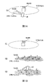
- FIG. 1A a scenario (Co-channel) in which both the macro cell and the small cell use the same frequency F1, and a macro cell and a small cell differ as shown in FIG. 1B.
- Scenarios Separated frequency, Non-co-channel
- F1 and F2 frequency bands
- FIG. 1B it is also considered to use different frequencies F2 and F3 between the small cells.
- a user terminal measures the reception quality (for example, RSRQ: Reference Signal Received Quality) of a measurement signal of a neighboring small cell and reports it to the network side.
- the network side determines whether or not to perform handover based on the reception quality reported from the user terminal.
- CCs component carriers
- the user terminal reports the reception quality of the measurement signal to the network side for each CC.
- the reception quality of the measurement signal is reported to the network side for each CC, the measurement load and the amount of report information in the user terminal increase.
- the present invention has been made in view of such points, and in a radio communication system in which a plurality of CCs are used in each small cell in a macro cell, a radio base station capable of reducing the measurement load and the amount of report information in a user terminal, It is an object to provide a user terminal and a communication control method.
- a radio base station is a radio base station that forms the macro cell in a radio communication system in which a plurality of component carriers (CC) are used in a small cell in the macro cell, and A transmitter for transmitting measurement instruction information including a report instruction for reception power of a specific CC in a cell; a receiver for receiving a measurement report including reception power of the specific CC from the user terminal; and the specific CC A calculation unit that calculates reception quality of the plurality of CCs based on the received power of the first CC.
- CC component carriers
- the present invention in a radio communication system in which a plurality of CCs are used in each small cell in a macro cell, it is possible to prevent an increase in measurement load and report information amount in a user terminal.
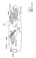
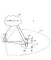
- FIG. 2 is an explanatory diagram of an example of a wireless communication system in which small cells are arranged in a macro cell.
- the radio communication system includes a radio base station forming a macro cell (hereinafter referred to as a macro base station (MeNB: Macro eNodeB)) and a radio base station forming a small cell 1-3 (hereinafter referred to as a small cell). It includes a base station (referred to as SeNB: Small eNodeB) 1-3 and a user terminal (UE: User Equipment).
- SeNB Small eNodeB
- UE User Equipment
- the macro cell uses a relatively low frequency band F1 such as 2 GHz or 800 MHz, and the small cell 1-3 uses a relatively high frequency such as 3.5 GHz or 10 GHz.
- the frequency band F2 is used.
- the small cells 1-3 are concentratedly arranged. Therefore, in the radio communication system shown in FIG. 2, the small cells 1-3 are switched on / off based on the traffic of the small cells 1-3, thereby reducing interference and power consumption between the small cells. Is being considered.
- the on state is a state in which data is transmitted and received, and is also referred to as a continuous transmission state.
- the small cell 1 small base station 1 with relatively high traffic is in an on state.
- a cell-specific reference signal CRS: Cell-specific Reference Signal
- PSS Primary Synchronization Signal
- SSS Secondary Synchronization Signal
- the off state is a state in which data transmission / reception is not performed, and is also referred to as a discontinuous transmission (DTX) state.
- DTX discontinuous transmission
- the small cells 2 and 3 small base stations 2 and 3 with relatively low traffic are in an off state.
- a discovery signal to be described later is transmitted in a longer cycle than CRS.
- transmission of CRS is omitted, so that interference between the small cells 1-3 and power consumption of the small base stations 2 and 3 can be reduced.
- each small cell (small base station) supports a plurality of component carriers (CC), and switching on / off states for each CC is also considered.
- CC1-3 is supported in each of the small cells 1-3.
- CCs 1 and 3 of the small cell 1 are in the on state
- CC2 of the small cell 2 is in the on state
- CCs 2 and 3 of the small cell 3 are in the on state.
- the user terminal is not sure which CC of the small cell 1-3 is in the on state (or off state). For this reason, the user terminal needs to measure the reception quality (for example, RSRQ) of CC1-3 of each of the small cells 1-3. Therefore, when the on / off state is switched for each CC of the small cell, the measurement load on the user terminal and the amount of information reported to the network side are increased as compared with the case of switching the on / off state for each small cell.
- RSRQ reception quality
- the user terminal connected to the macro cell interrupts communication with the macro cell in order to measure the reception quality of the CC 1-3 of each of the small cells 1-3 (different frequency measurement (Inter- frequency measurement)).
- the interruption time of communication with the macrocell increases, and the throughput may be reduced.
- the user terminal can perform carrier aggregation (CA) by integrating the CCs in the on state.
- CA carrier aggregation
- a plurality of CCs in a single small cell may be integrated, or a plurality of CCs in different small cells may be integrated.
- F1 for example, 2 GHz
- F2 for example, 3.5 GHz
- CCs 2 and 3 of the small cell 3 are integrated.
- the RSRP Reference Signal Received Power
- the RSRQ is measured as the received quality of the desired signal
- the RSSI Receiveived Signal Strength
- Indicator is measured, but is not limited to this.
- SINR Signal to Interference Noise Ratio
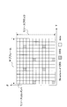
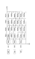
- FIG. 5 is an explanatory diagram of measurement of RSRP and RSRQ using CRS. As shown in FIG. 5, CRS is arranged in a part of OFDM symbols of each subframe. The user terminal measures received power per resource element in which CRS is arranged as RSRP.
- the user terminal measures received power per resource block (that is, a resource block in which CRS is arranged) shown in FIG. 5 as RSSI.
- RSSI is the sum of received power of CRS.
- RSSI is the sum of the received power of CRS, the received power of traffic data, interference power, and the like.
- the traffic load is reflected in RSSI.
- the user terminal measures RSRQ based on RSRP and RSSI.
- the user terminal may calculate RSRQ according to equation (1).
- N is a parameter indicating the bandwidth, and may be the number of resource blocks, for example.
- i is a CC subscript
- j is a small cell subscript.
- RSRQ ij (N * RSRP ij ) / RSSI i (1)
- the user terminal measures RSRP and RSRQ of a maximum of 4 small cells for a maximum of 3 CCs and reports them to the network side.
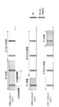
- FIG. 6 is an explanatory diagram of measurement of RSRP and RSRQ using a discovery signal (DS).
- FIG. 6 shows the state of CC1 of each of the small cells 1-3.
- the user terminal since CRS is transmitted in the ON state, the user terminal can measure RSRP and RSRQ using CRS as described above.
- CRS since CRS is not transmitted in the off state, it is considered that the user terminal measures RSRP using a discovery signal instead of CRS.
- the discovery signal is a signal for measuring received power in a small cell.
- the discovery signal may be a detection signal used for detecting a small cell.
- the discovery signal is a reference signal such as CRS, CSI-RS (Channel State Information-Reference Signal), PRS (Positioning Reference Signal), or a synchronous signal such as PSS (Primary Synchronization Signal) or SSS (Secondary Synchronization Signal). Based on this, a new signal may be defined.
- the discovery signal is transmitted in a DS transmission period repeated in the DS transmission cycle.
- the DS transmission cycle is a predetermined cycle such as 100 ms or 160 ms, and is a cycle longer than CRS.
- the DS transmission period is a period during which a discovery signal is transmitted, and is, for example, 1 ms. In the DS transmission period, the discovery signal may be arranged with a higher arrangement density than the CRS.
- FIG. 7 is an explanatory diagram of the measurement time for each CC using the discovery signal.
- the DS transmission period of each CC in one small cell is shown.
- the discovery signal has a different DS transmission period for each CC.
- the total measurement time in the user terminal is at least the total of the DS transmission periods of CC1-3.
- the DS transmission period of each CC is the same timing.
- the total measurement time in the user terminal depends on the number of reception circuits (RF circuits) in the user terminal. For example, when a user terminal has a single receiving circuit, the user terminal can receive only a discovery signal of 1 CC in a certain DS transmission period.
- the user terminal when the user terminal has a single receiving circuit, the user terminal measures the RSRP of CC1 in the DS transmission period t1, and measures the RSRP of CC2 in the DS transmission period t2, as shown in FIG. 7B. Then, the RSRP of the CC3 discovery signal is measured in the DS transmission period t3. In this case, the total measurement time in the user terminal is at least the sum of the DS transmission periods t1-t3.
- the user terminal reports RSRP and RSRQ of a plurality of CCs to the network side in each small cell, it is assumed that the measurement load and the amount of report information in the user terminal become a problem.
- the present inventors pay attention to the fact that RSRP between a plurality of CCs in the same small cell does not change so much, and by measuring the RSRP of a specific CC, it is assumed that the RSRPs of other CCs are the same.
- the present inventors conceived of preventing an increase in measurement load and report information amount in the user terminal, and the present invention has been achieved.
- a macro base station sends an RSRP (measurement signal for a specific CC in the small cell to a user terminal.
- Measurement instruction information including a measurement instruction of (received power).
- the macro base station receives a measurement report including RSRP of the specific CC from the user terminal.
- the macro base station calculates RSRQ (reception quality of measurement signals) of a plurality of CCs based on the RSRP of the specific CC.
- the user terminal since the macro base station considers that the RSRP of a specific CC in a small cell is the same as the RSRP of another CC, the user terminal measures the RSRP of the specific CC. And report. For this reason, compared with the case where RSRP of all CC is measured and reported, the measurement load and report information amount in a user terminal can be reduced.
- a discovery signal is used as the measurement signal.
- RSRP is used as the reception power of the measurement signal
- RSSI is used as the total reception power
- RSRQ is used as the reception quality of the measurement signal, but is not limited thereto.
- the user terminal measures RSRP of a specific CC and RSSI in a plurality of CCs based on measurement instruction information from the macro base station, and transmits a measurement report to the macro base station.
- the macro base station calculates RSRQ in a plurality of CCs based on the RSRP of a specific CC included in the measurement report and the RSSI in the plurality of CCs.
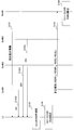
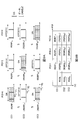
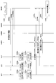
- FIG. 8 is a sequence diagram showing a communication control method according to the first aspect.
- FIG. 9 is an explanatory diagram of the communication control method according to the first aspect. 8 and 9 assume a wireless communication system (FIG. 2) in which small cells 1-3 are arranged in a macro cell. In addition, it is assumed that CC1-3 is used in each of the small cells 1-3.
- the macro base station transmits measurement instruction information for instructing measurement of RSRP in CC1 and RSSI in CC1-CC3 to the user terminal (step S101).
- the measurement instruction information may be transmitted using higher layer signaling such as RRC signaling or broadcast information. Further, the measurement instruction information may be transmitted from the small base station.
- PCI Physical Cell Identifier
- each small base station transmits the CC1-3 discovery signal at the same timing (see FIG. 7B), but may transmit it at different timings (see FIG. 7A).
- the user terminal Based on the measurement instruction information, the user terminal measures the RSRP of a specific CC (here, CC1) in each small cell (step S103). Specifically, the user terminal measures RSRP (RSRP 11 , RSRP 12 , RSRP 13 ) in the DS transmission period of the small cell 1-3 of CC 1 in FIG. 9A.
- a specific CC here, CC1
- RSRP RSRP 11 , RSRP 12 , RSRP 13
- the user terminal omits measurement of RSRP 21 , RSRP 22 , and RSRP 23 of the small cell 1-3 in CC2.
- the user terminal omits measurement of RSRP 31 , RSRP 32 , and RSRP 33 of small cell 1-3 in CC 3.
- a user terminal measures RSSI of each CC based on the said measurement instruction information. Specifically, the user terminal measures the RSSI (RSSI 1 , RSSI 2 , RSSI 3 ) of each CC 1-3 (step S 104). Since RSSI is the total received power including desired received power, interference power, noise, and the like, the RSSI in each CC is common among the small cells. RSSI may also be measured before RSRP.
- the RSSI measurement period may be a predetermined time unit, such as a subframe or an OFDM symbol.
- RSRP is measured using a discovery signal during a DS transmission period.
- the DS transmission period it is assumed that only discovery signals are transmitted and other signals (for example, data signals, CRS, PSS / SSS, etc.) are not transmitted. For this reason, the load of the small cell in the on state is not reflected in the RSSI in the DS transmission period.
- the user terminal measures RSSI 1 -RSSI 3 of CC1 to CC3 in a measurement period T1-T3 during which no discovery signal is transmitted.
- a data signal, CRS, or the like is transmitted in the on state, and is not transmitted in the off state. For this reason, the load according to the on / off state of the small cell is reflected.
- the RSSI measurement period T1-T3 is specified using one of the following methods (1) to (3).
- the user terminal specifies a discovery signal transmission period based on discovery signal configuration information (hereinafter, DS configuration information), and sets a predetermined period other than the transmission period as the measurement period T1-T3.
- DS configuration information is notified from the macro base station to the user terminal, and may include at least one of a DS transmission period, a DS transmission period, a DS transmission period start offset, and a sequence pattern.
- the measurement period T1-T3 can be implicitly notified to the user terminal by notification of the DS configuration information.
- the user terminal specifies the measurement periods T1 to T3 based on the measurement period information notified explicitly.
- the measurement period information is information indicating the measurement period, and may be a relative position such as an offset with respect to the discovery signal transmission period, or may be an absolute position such as a subframe number or an OFDM symbol number. Further, the measurement period information may be notified from the macro base station to a user terminal in a connected state (for example, RRC_CONNECTED).
- the user terminal specifies the measurement period T1-T3 based on the prior rule.
- the prior rule is a rule stored in the user terminal in advance, for example, a subframe next to a discovery signal transmission subframe is set as a measurement period.
- the user terminal transmits, to the macro base station, a measurement report (Measurement Report) including the RSRP of the specific CC in each small cell measured in step S103 and the RSSI of each CC measured in step S104 (step S104). S105). Specifically, the user terminal reports a measurement report including RSRP 11 , RSRP 12 and RSRP 13 of small cells 1 , 2 and 3 in CC 1 and RSSI 1 , RSSI 2 and RSSI 3 in CCs 1 , 2 and 3. Send.
- a measurement report including RSRP 11 , RSRP 12 and RSRP 13 of small cells 1 , 2 and 3 in CC 1 and RSSI 1 , RSSI 2 and RSSI 3 in CCs 1 , 2 and 3.
- the macro base station calculates RSRQs of a plurality of CCs in each small cell based on the measurement report from the user terminal (step S106). Specifically, as illustrated in FIG. 9B, the macro base station uses RSRQ 11, RSRQ 12, RSRQ 13 of small cells 1, 2, and 3 in CC1 , and uses RSRP 11, RSRP 12, RSRP 13, and RSSI 1 . To calculate. For example, RSRQ 11, RSRQ 12, and RSRQ 13 may be calculated using the above formula (1).
- the RSRP 21, RSRP 22, and RSRP 23 of the small cells 1, 2, and 3 in CC2 are substantially equal to the RSRP 11, RSRP 12, and RSRP 13 of the small cells 1, 2, and 3 in CC1, respectively.
- Measurement at the user terminal and reporting to the macro base station are omitted.
- the macro base station calculates RSRQ 21, RSRQ 22, and RSRQ 23 of CC2 using RSRP 11, RSRP 12, RSRP 13 of CC1, and RSSI 2 of CC2.
- the macro base station calculates the RSRQ 31, RSRQ 32, and RSRQ 33 of CC3 using the RSRP 11, RSRP 12, RSRP 13, and the RSSI 3 of CC3 of CC1.
- RSRQ 21 -RSRQ 33 may be calculated using Equation (1) above.
- the user terminal when a plurality of CCs are used in each small cell, the user terminal only measures and reports the RSRP of each small cell in a specific CC.
- the macro base station can calculate the RSRQ of each small cell in all CCs. For this reason, compared with the case where RSRP of each small cell in all CC is measured and reported, the measurement load and report information amount in a user terminal can be reduced.
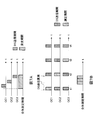
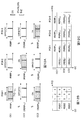
- FIG. 10 is an explanatory diagram of the effect of the communication control method according to the first aspect.
- the user terminal measures RSRP 11 , RSRP 12 , RSRP 13 of small cell 1-3 in the DS transmission period of CC1, and no discovery signal is transmitted.
- measurement period T1-T3 RSSI 1 -RSSI 3 of CC1-3 is measured.
- measurement of the DS transmission periods of CCs 2 and 3 can be omitted, so that the measurement load can be reduced.
- the RSSI measurement periods T1-T3 may not be provided.
- the user terminal measures RSRP 11 -RSRP 13 using a discovery signal in a part (for example, OFDM symbol) within the DS transmission period (for example, subframe) of CC1, and CRS, data signal, etc. Measure RSSI 1 for the remaining time included (eg, OFDM symbol).
- the user terminal measures RSSI 2 and RSSI 3 in a time (for example, OFDM symbol) in which CRS, data signals, and the like within the DS transmission period of CC2 and CC3 are included.
- the communication control method according to the first aspect it is only necessary to report 1-CC maximum RSRP of 4 cells and maximum 3-CC RSSI. For this reason, the report information amount of a user terminal becomes the sum of the information amount of a maximum of 4 RSRP and a maximum of 3 RSSI.
- RSSI has a smaller amount of information than RSRQ. Therefore, the communication control method according to the first aspect can reduce the amount of report information compared to Release 11.
- the user terminal transmits a measurement report including the RSRP of the specific CC and the RSRQ of the specific CC to the macro base station based on the measurement instruction information from the macro base station. .
- the macro base station calculates RSRQ in a plurality of CCs based on the RSRP of the specific CC and the RSRQ of the specific CC included in the measurement report.
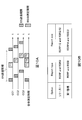
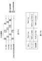
- FIG. 11 is a sequence diagram showing a communication control method according to the second aspect.
- FIG. 12 is an explanatory diagram of the communication control method according to the second aspect. The communication control method according to the following second aspect will be described focusing on the differences from the communication control method according to the first aspect.
- the macro base station transmits measurement instruction information for instructing measurement of RSRP in CC1 and RSRQ in CC1 to the user terminal (step S201).
- the communication control method according to the second aspect is different from the first aspect in that the measurement instruction information includes an RSRQ measurement instruction of CC1 instead of an RSSI measurement instruction in CC1-3.
- the small base station 1-3 transmits a CC1 discovery signal (steps S202a to S202c).
- the small base stations 1-3 can omit the transmission of discovery signals of CCs (here, CC2 and CC3) that are not instructed by the measurement instruction information.
- CCs here, CC2 and CC3
- the details of steps S202 and S203 in FIG. 11 are the same as steps S102 and S103 in FIG.
- the user terminal measures RSSI 1 in CC 1 in order to obtain RSRQ in CC 1 (step S204). Specifically, as shown in FIG. 12A, RSSI 1 of CC1 is measured in a measurement period T1 during which no discovery signal is transmitted. In the communication control method according to the second aspect, unlike the first aspect, the RSSI 2 and RSSI 3 of CCs 2 and 3 are not measured.
- the user terminal receives the RSRQ 11, RSRQ 12, and RSRQ 13 of the small cells 1, 2, and 3 in CC1, the RSRP 11, RSRP 12, and RSRP 13 measured in step S203, and the RSSI 1 calculated in step S204.
- the user terminal may calculate RSRQ 11, RSRQ 12, and RSRQ 13 using the above equation (1).
- the user terminal transmits a measurement report including RSRP 11, RSRP 12, and RSRP 13 measured in step S203 and RSRQ 11, RSRQ 12, and RSRQ 13 calculated in step S205 to the macro base station (step S206). ).
- the macro base station calculates the RSSI 2 and RSSI 3 of CC 2 and 3 based on the RSRP 11, RSRP 12 and RSRP 13 of CC 1 included in the measurement report, and the on / off states of the small cells of CC 2 and 3 ( Step S207). Specifically, the macro base station may calculate RSSI 2 and RSSI 3 using Equation (2).
- RSSI i ⁇ j RSRP ij * (N PDSCH_RE * load ij + N CRS_RE ) ... Formula (2)
- i is a CC subscript and j is a small cell subscript.
- Load ij is a parameter based on the on / off state of the small cell j in CCi. For example, Load ij may be set to “1” when the small cell j in CCi is on, and may be set to “0” when the small cell j in CCi is off. For example, in the case shown in FIG. 12A, Load ij is set as shown in FIG. 12B.
- N CRS_RE is the number of CRS resource elements arranged in one OFDM symbol in one resource block. For example, as shown in FIG. 5, in the case of 1-antenna transmission, NCRS_RE is “2”. On the other hand, in the case of 2-antenna transmission (not shown), NCRS_RE is “4”.
- N PDSCH_RE is the number of PDSCH resource elements arranged in one OFDM symbol in one resource block. For example, as shown in FIG. 5, in the case of 1 antenna transmission, N PDSCH_RE is “10”. On the other hand, in the case of two-antenna transmission (not shown), N PDSCH_RE is “8”.
- RSSI 2 is calculated as follows using the above equation (2). Is done.
- RSRP 21 , RSRP 22 , and RSRP 23 not included in the measurement report are regarded as substantially equal to RSRP 11 , RSRP 12 , and RSRP 13 , respectively.
- RSSI 2 RSRP 21 * (N PDSCH_RE * 0 + N CRS_RE ) + RSRP 22 * (N PDSCH_RE * 1 + N CRS_RE ) + RSRP 23 * (N PDSCH_RE * 0 + N CRS_RE )
- RSSI 3 is calculated as follows using the above equation (2). Is done.
- RSRP 31 , RSRP 32 , and RSRP 33 that are not included in the measurement report are considered to be approximately equal to RSRP 11 , RSRP 12 , and RSRP 13 , respectively.
- RSSI 3 RSRP 31 * (N PDSCH_RE * 1 + N CRS_RE ) + RSRP 32 * (N PDSCH_R * 0 + N CRS_RE ) + RSRP 23 * (N PDSCH_RE * 1 + N CRS_RE )
- the macro base station may correct the RSSI 2 and RSSI 3 of CCs 2 and 3 (step S208). Specifically, the macro base station calculates RSSI 1 using Equation (2) above, and calculates RSSI 1 based on RSRP 11 -RSRP 13 and RSRQ 11 -RSRQ 13 included in the measurement report. . The macro base station corrects RSSI 2 and RSSI 3 of CCs 2 and 3 based on the comparison result between the two . For example, the macro base station may add the difference (true value) between both to RSSI 1 and RSSI 2 . Thus, it is possible to reflect the influence of noise such as RSSI 2, RSSI 3.
- the macro base station calculates RSRQ 21 -RSRQ 23 , RSRQ 31 -RSRQ 33 based on the RSRP 11 , RSRP 12 , RSRP 13 reported from the user terminal and the calculated RSSI 2, RSSI 3 (steps). S209).
- the user terminal measures and reports the RSRP and RSRQ of each small cell in the specific CC. Only, the macro base station can calculate the RSRQ of each small cell in all CCs. For this reason, compared with the case where RSRP and RSRQ of each small cell in all CC are measured and reported, the measurement load and report information amount in a user terminal can be reduced.
- FIG. 13 is an explanatory diagram of the effect of the communication control method according to the second aspect.
- the user terminal measures RSRP 11 , RSRP 12 , RSRP 13 of the small cell 1-3 in the DS transmission period of CC1, and no discovery signal is transmitted.
- RSSI 1 of CC1 is measured.
- measurement of the DS transmission periods of CC2 and 3 and measurement of RSSI 2 and RSSI 3 in measurement periods T2 and T3 can be omitted, so that the measurement load can be reduced.
- transmission of CCs 2 and 3 can be omitted.
- the RSSI measurement period T1 may not be provided.
- the user terminal may report RSCC of a maximum of 4 cells of 1 CC and RSRQ of a maximum of 4 cells of 1 CC. Therefore, in the communication control method according to the second aspect, the amount of report information can be reduced as compared with Release 11. Further, in the communication control method according to the second correspondence, since the type of information to be reported as Release 11 (that is, RSRP and RSRQ) is the same, it is not necessary to update the report type.
- a communication control method will be described with reference to FIGS.
- a plurality of user terminals within a predetermined range are grouped.
- Each user terminal in the group is specified to be different from other user terminals based on the measurement instruction information from the macro base station, the RSRP of the specific CC in the specific small cell, and the specific CC of the specific CC RSSI is measured and a measurement report is transmitted to the macro base station.
- the macro base station calculates the RSRQ of all CCs based on the measurement report from each user terminal in the group.
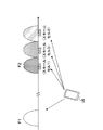
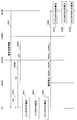
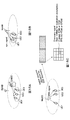
- FIG. 14 is a sequence diagram showing a communication control method according to the third aspect.
- 15 and 16 are explanatory diagrams of the communication control method according to the third aspect. Note that the communication control method according to the following third aspect will be described focusing on differences from the communication control method according to the first aspect.
- the macro base station groups a plurality of user terminals located within a predetermined range (step S301). Specifically, as shown in FIG. 15A, a plurality of user terminals may be grouped using GNSS (Global Navigation Satellite System) or GPS (Global Positioning System). In such a case, each of the plurality of user terminals transmits position information from GNSS and GPS to the macro base station.
- the macro base station groups a plurality of user terminals whose positions indicated by the position information are within a predetermined range.
- reception quality of measurement signals eg, CRS, CSI-RS, PSS, SSS, etc.
- a macro base station or a small base station not shown
- User terminals may be grouped. In such a case, each user terminal measures the reception quality of the measurement signal from the macro base station and reports the measurement result to the macro base station.
- a plurality of user terminals whose reception quality is within a predetermined range are estimated to be located within the predetermined range. For this reason, the macro base station groups a plurality of user terminals whose reception quality is within a predetermined range.
- a plurality of user terminals may be grouped using a D2D (Device to Device) function.
- the D2D function is a function of performing communication between user terminals without using a base station.
- the user terminal recognizes other user terminals in the vicinity by transmitting and detecting discovery signals between the user terminals, and the macro base station groups a plurality of user terminals based on the report of the recognition result. To do.
- the macro base station designates a specific small cell and a specific CC for each grouped user terminal so as to be different from other user terminals in the group.
- the small cell 3 and CC2 are designated with respect to the user terminal 2.
- the small cell 4 and CC3 are designated with respect to the user terminal 3.
- the macro base station provides measurement instruction information including RSRP measurement of a specific CC and RSSI of the specific CC to each user terminal in the group. Transmit (steps S302a-302c).
- Each user terminal in the group measures the RSRP of a specific CC in a specific small cell indicated by the measurement instruction information (steps S303a to 303c).
- the small base stations 1-3 transmit CC1-CC3 discovery signals, respectively.
- the user terminal 1 measures RSRP 11 and RSRP 12 of CC1 in the small cells 1 and 2.
- the user terminal 2 measures the RSRP 23 of the CC 2 in the small cell 3.
- the user terminal 3 measures the RSRP 34 of CC3 in the small cell 4.
- Each user terminal in the group measures the RSSI of a specific CC indicated by the measurement instruction information (steps S304a to 304c). For example, in the case illustrated in FIG. 16, the user terminal 1 measures the RSSI 1 of CC1, the user terminal 2 measures the RSSI 2 of CC2, and the user terminal 3 measures the RSSI 3 of CC3.
- Each user terminal in the group transmits a measurement report including the measured RSRP and RSSI to the macro base station (steps S305a to S305c). Details of the RSRP and RSSI measurement processing in the user terminal are the same as steps S103 and S104 in FIG.
- the macro base station calculates RSRQs of a plurality of CCs in each small cell based on the measurement report from each user terminal in the group (step S306). For example, in the case illustrated in FIG. 16, the macro base station calculates RSRQ 11 and RSRQ 12 of CC1 in the small cells 1 and 2 based on RSRP 11 , RSRP 12 and RSSI 1 reported from the user terminal 1.
- the macro base station calculates RSRQ 21 and RSRQ 22 of CC2 in the small cells 1 and 2 based on RSRP 11 and RSRP 12 reported from the user terminal 1 and RSSI 2 reported from the user terminal 2. . Further, the macro base station calculates RSRQ 31 and RSRQ 32 of CC3 in the small cells 1 and 2 based on RSRP 11 and RSRP 12 reported from the user terminal 1 and RSSI 3 reported from the user terminal 3. .
- the macro base station determines the RSRQ 13 and RSRQ of CC1-3 in the small cell 3 based on the RSRP 23 reported from the user terminal 2 and the RSSI 1 -RSSI 3 reported from the user terminal 1-3. 23 , RSRQ 33 is calculated. Further, the macro base station determines the RSRQ 14 and RSRQ 24 of CC1-3 in the small cell 4 based on the RSRP 34 reported from the user terminal 3 and the RSSI 1 -RSSI 3 reported from the user terminal 1-3. , RSRQ 34 is calculated.
- the communication control method when a plurality of CCs are used in each small cell, one user terminal measures the RSRP and RSSI of a specific CC in the specific small cell, and By simply reporting, the macro base station can calculate the RSRQ of each small cell in all CCs. For this reason, compared with the case where RSRP and RSRQ of each small cell in all CCs are measured and reported, the measurement load and report information amount per user terminal can be reduced.
- FIG. 17 is an explanatory diagram of the effect of the communication control method according to the third aspect.
- the user terminal 1 measures RSRP 11 and RSRP 12 in the DS transmission period of CC1, and measures RSSI 1 in the measurement period T1 in which no discovery signal is transmitted.
- the user terminal 2 measures the RSRP 23 in the DS transmission period of CC2, and measures RSSI 2 in the measurement period T2 in which no discovery signal is transmitted.
- the user terminal 3 measures RSRP 34 in the DS transmission period of CC3, and measures RSSI 3 in the measurement period T3 in which no discovery signal is transmitted.
- the whole measurement time per user terminal can be shortened, and a measurement load can be reduced.
- the RSSI measurement period T1 may not be provided.
- each user terminal in the group may report the RSRP and RSSI assigned to the own terminal.
- the sum of 2RSRP and 1RSSI reported by the user terminal 1 is the maximum amount of report information.
- RSSI has a smaller amount of information than RSRQ. Therefore, the communication control method according to the third aspect can reduce the amount of report information as compared to Release 11.
- a discovery signal is used as a measurement signal.
- RSRP is used as the reception power of the measurement signal
- RSSI is used as the total reception power
- RSRQ is used as the reception quality of the measurement signal, but is not limited thereto.
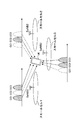
- FIG. 18 is a schematic configuration diagram of the radio communication system according to the present embodiment.
- the radio communication system 1 includes a macro base station 11 that forms a macro cell C1, and small base stations 12a and 12b that are arranged in the macro cell C1 and form a small cell C2 that is narrower than the macro cell C1. I have.
- the user terminal 20 is arrange
- the user terminal 20 is arranged in the macro cell C1 and each small cell C2.
- the user terminal 20 is configured to be able to wirelessly communicate with the macro base station 11 and / or the small base station 12.
- a relatively low frequency band F1 (for example, 2 GHz) is used between the user terminal 20 and the macro base station 11.
- a relatively high frequency band F2 (for example, 3.5 GHz) is used between the user terminal 20 and the small base station 12.
- F1 for example, 2 GHz
- F2 for example, 3.5 GHz
- a plurality of frequency bands may be used.
- the macro base station 11 and the small base station 12 may use the same frequency band.
- the macro base station 11 and each small base station 12 may be connected by a relatively low speed line (Non-Ideal backhaul) such as an X2 interface, or may be relatively high speed (low delay) such as an optical fiber. ) Line (Ideal backhaul) or wireless connection.
- the small base stations 12 may be connected by a relatively low speed line (Non-Ideal backhaul) such as an X2 interface, or may be connected by a relatively high speed line (Ideal backhaul) such as an optical fiber. Or may be wirelessly connected.
- the macro base station 11 and each small base station 12 are each connected to the core network 30.
- the core network 30 is provided with core network devices such as MME (Mobility Management Entity), S-GW (Serving-Gateway), and P-GW (Packet-Gateway).
- MME Mobility Management Entity
- S-GW Serving-Gateway
- P-GW Packet-Gateway
- the macro base station 11 is a radio base station having a relatively wide coverage, and may be called an eNodeB, a macro base station, an aggregation node, a transmission point, a transmission / reception point, or the like.
- the small base station 12 is a radio base station having local coverage, such as a small base station, a pico base station, a femto base station, a HeNB (Home eNodeB), an RRH (Remote Radio Head), a micro base station, a transmission point, It may be called a transmission / reception point.
- the user terminal 20 is a terminal that supports various communication schemes such as LTE, LTE-A, and FRA, and may include not only a mobile communication terminal but also a fixed communication terminal.
- a downlink physical channel a physical downlink shared channel (PDSCH) shared by each user terminal 20, a physical downlink control channel (PDCCH), and an EPDCCH : Enhanced Physical Downlink Control Channel), physical broadcast channel (PBCH), etc. are used.
- PDSCH physical downlink shared channel
- PDCCH physical downlink control channel
- EPDCCH Enhanced Physical Downlink Control Channel
- PBCH physical broadcast channel
- DCI Downlink control information
- PUSCH physical uplink shared channel
- PUCCH physical uplink control channel
- User data and higher layer control information are transmitted by PUSCH.
- downlink radio quality information CQI: Channel Quality Indicator
- ACK / NACK delivery confirmation information
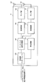
- FIG. 19 is an overall configuration diagram of the radio base station 10.
- the radio base station 10 includes a plurality of transmission / reception antennas 101 for MIMO transmission, an amplifier unit 102, a transmission / reception unit 103 (transmission unit, reception unit), a baseband signal processing unit 104, A call processing unit 105 and a transmission path interface 106 are provided.
- user data transmitted from the radio base station 10 to the user terminal 20 is input from the S-GW provided in the core network 30 to the baseband signal processing unit 104 via the transmission path interface 106.
- the baseband signal processing unit 104 performs PDCP layer processing, user data division / combination, RLC layer transmission processing such as RLC (Radio Link Control) retransmission control transmission processing, MAC (Medium Access Control) retransmission control, for example, HARQ transmission processing, scheduling, transmission format selection, channel coding, Inverse Fast Fourier Transform (IFFT) processing, and precoding processing are performed and transferred to each transceiver 103. Also, downlink control signals (including reference signals, synchronization signals, broadcast signals, etc.) are subjected to transmission processing such as channel coding and inverse fast Fourier transform, and transferred to each transmitting / receiving unit 103.
- RLC layer transmission processing such as RLC (Radio Link Control) retransmission control transmission processing, MAC (Medium Access Control) retransmission control, for example, HARQ transmission processing, scheduling, transmission format selection, channel coding, Inverse Fast Fourier Transform (IFFT) processing, and precoding processing are performed and transferred to each transceiver 103.
- Each transmission / reception unit 103 converts the downlink signal output from the baseband signal processing unit 104 by precoding for each antenna to a radio frequency.
- the amplifier unit 102 amplifies the frequency-converted radio frequency signal and transmits the amplified signal using the transmission / reception antenna 101.
- the radio frequency signal received by each transmitting / receiving antenna 101 is amplified by the amplifier unit 102, frequency-converted by each transmitting / receiving unit 103, converted into a baseband signal, and sent to the baseband signal processing unit 104. Entered.
- the baseband signal processing unit 104 performs FFT processing, IDFT processing, error correction decoding, MAC retransmission control reception processing, RLC layer, and PDCP layer reception processing on user data included in the input uplink signal.
- the data is transferred to the core network 30 via the transmission path interface 106.
- the call processing unit 105 performs call processing such as communication channel setting and release, status management of the radio base station 10, and radio resource management.
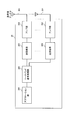
- FIG. 20 is an overall configuration diagram of the user terminal 20 according to the present embodiment.
- the user terminal 20 includes a plurality of transmission / reception antennas 201 for MIMO transmission, an amplifier unit 202, a transmission / reception unit 203 (transmission unit, reception unit), a baseband signal processing unit 204, and an application unit 205.
- the user terminal 20 may switch the reception frequency by one reception circuit (RF circuit) or may have a plurality of reception circuits.
- radio frequency signals received by a plurality of transmission / reception antennas 201 are respectively amplified by an amplifier unit 202, frequency-converted by a transmission / reception unit 203, and input to a baseband signal processing unit 204.
- the baseband signal processing unit 204 performs FFT processing, error correction decoding, reception processing for retransmission control, and the like.
- User data included in the downlink signal is transferred to the application unit 205.
- the application unit 205 performs processing related to layers higher than the physical layer and the MAC layer. Also, broadcast information in the downlink data is also transferred to the application unit 205.
- uplink user data is input from the application unit 205 to the baseband signal processing unit 204.
- the baseband signal processing unit 204 performs transmission processing for retransmission control (H-ARQ (Hybrid ARQ)), channel coding, precoding, DFT processing, IFFT processing, and the like, and transfers them to each transmission / reception unit 203.
- the transmission / reception unit 203 converts the baseband signal output from the baseband signal processing unit 204 into a radio frequency. Thereafter, the amplifier unit 202 amplifies the frequency-converted radio frequency signal and transmits the amplified signal using the transmitting / receiving antenna 201.
- the functional configuration of the macro base station 11 illustrated in FIG. 21 and the small base station 12 illustrated in FIG. 22 is mainly configured by the baseband signal processing unit 104.
- the functional configuration of the user terminal 20 illustrated in FIG. 23 is mainly configured by the baseband signal processing unit 204.
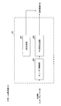
- FIG. 21 is a functional configuration diagram of the macro base station 11 according to the present embodiment.
- the macro base station 11 includes a measurement instruction generation unit 301, a calculation unit 302, a grouping unit 303, and an on / off control unit 304.
- the grouping unit 303 may be omitted in the first aspect and the second aspect of the present invention.
- the measurement instruction generation unit 301 generates measurement instruction information including a measurement instruction for the user terminal 20.
- the measurement instruction information may include a measurement instruction of the RSRP of the specific CC and the RSSI of the specific CC (first mode).
- the measurement instruction information may include a measurement instruction of RSRP and RSRQ of a specific CC (second mode).
- the measurement instruction information may include a measurement instruction of the RSRP of a specific CC and the RSSI of the specific CC in a specific small cell C2 assigned by the grouping unit 303 described later (third mode).
- the measurement instruction information measured by the measurement instruction generation unit 301 is input to the transmission / reception unit 103 and transmitted to the user terminal 20.
- the measurement instruction information may be transmitted using higher layer signaling such as RRC signaling or broadcast information.
- the measurement report is input from the transmission / reception unit 103 to the calculation unit 302.
- the calculation unit 302 calculates the RSRQ of a plurality of CCs based on the RSRP of a specific CC included in the measurement report.
- the measurement report includes RSSIs of a plurality of CCs in addition to RSRPs of specific CCs.
- the calculation unit 302 based on the RSRP of the specific CC (eg, CC1) and the RSSI of the plurality of CCs (eg, CC1-3) included in the measurement report, RSRQ is calculated (see FIG. 9B).
- the measurement report includes the RSRQ of the specific CC in addition to the RSRP of the specific CC in each small cell C2.
- the calculation unit 302 determines the other CC based on the RSRP of a specific CC (eg, CC1) in each small cell C2 and the on / off state of other CCs (eg, CC2, CC3). Calculate the RSSI of the CC.
- the calculation unit 302 calculates the RSRQ of the other CC based on the RSRP of the specific CC (for example, CC1) and the calculated RSSI of the other CCs (for example, CC2 and 3) (FIG. 12B and FIG. 12B). 12C).
- the calculation unit 302 may calculate the RSSI of the specific CC based on the RSRP of the specific CC (for example, CC1) in each small cell C2 and the RSRQ of the specific CC. Good. In this case, the calculation unit 302 calculates the RSSI of the specific CC based on the RSRP of the specific CC in each small cell C2 and the on / off state of the specific CC. The calculation unit 302 may correct the RSSI of other CCs (for example, CC2 and CC3) based on the calculated comparison result of both RSSIs.
- the measurement report from each user terminal 20 in the group includes the RSRP of a specific CC in a different specific small cell C2 and the RSSI of the specific CC.
- the calculation unit 302 calculates the RSRQ of the specific CC based on the RSRP of the specific CC (for example, CC1) reported from a certain user terminal 20 and the RSSI of the specific CC ( (See FIG. 16). Further, the calculation unit 302 calculates the RSRQ of the other CC based on the RSRP of the specific CC reported from the certain user terminal 20 and the RSSI of the other CC reported from the other user terminal ( (See FIG. 16).
- the grouping unit 303 groups a plurality of user terminals 20 located within a predetermined range.
- the several user terminal 20 may be grouped based on the positional information from GNSS or GPS (FIG. 15A).
- the plurality of user terminals 20 may be grouped based on reception quality of measurement signals (for example, CRS, CSI-RS, PSS, SSS, etc.) from the macro base station 11 (FIG. 15B).
- the plurality of user terminals 20 may be grouped based on the D2D function (FIG. 15C).
- the grouping unit 303 designates a specific small cell C2 and a specific CC for the user terminals in the group so that they are different from other user terminals in the group.
- the grouping unit 303 outputs the designation result to the measurement instruction generation unit 301.
- the on / off determination unit 304 determines the on / off state of each small cell C2 for each CC based on the calculation result by the calculation unit 302. Further, the on / off determination unit 304 notifies the small base station 12 of the determination result.
- FIG. 22 is a functional configuration diagram of the small base station 12 according to the present embodiment.
- the small base station 11 includes a discovery signal (DS) generation unit 401, an on / off control unit 402, and a downlink signal generation unit 403.
- DS discovery signal
- the DS generation unit 401 generates a discovery signal for each CC and maps it to predetermined radio resources (for example, time resources such as subframes and OFDM symbols, and frequency resources such as resource blocks).
- predetermined radio resources for example, time resources such as subframes and OFDM symbols, and frequency resources such as resource blocks).
- the generated discovery signal is input to the transmission / reception unit 103 and transmitted in the DS transmission period repeated in the DS transmission cycle.
- the DS transmission cycle is a transmission cycle longer than CRS or the like.
- the discovery signal may be transmitted with a different DS transmission period for each CC (see FIG. 7A), or may be transmitted with the same DS transmission period between CCs (see FIG. 7B). Further, the discovery signal may be transmitted in synchronization with the adjacent small base station 12 (see FIG. 6).
- DS configuration information including a DS transmission period, a DS transmission period, a DS transmission period start offset, a sequence pattern, and the like may be notified from the small base station 12 to the user terminal, or from the macro base station 11 to the user terminal 20. May be notified.
- the on / off control unit 402 controls the on / off state of the small base station 12 based on an instruction from the macro base station 11.
- the downlink signal generation unit 403 When the downlink signal generation unit 403 is in the on state, the downlink signal generation unit 403 generates a downlink signal and maps it to a predetermined radio resource.
- the downlink signal may include a data (PDSCH) signal, CRS, CSI-RS, SSS / PSS, and the like.
- the downlink signal generation unit 403 stops the generation of the downlink signal when it is in the off state. Thereby, in the off state, the power consumption of the small base station 12 can be reduced.
- FIG. 23 is a functional configuration diagram of the user terminal 20 according to the present embodiment.
- the user terminal 20 includes a measurement unit 501 and a measurement report generation unit 502.
- the measurement unit 501 includes an RSRP measurement unit 5011, an RSSI measurement unit 5012, and an RSRQ calculation unit 5013.
- the RSRQ calculation unit 5013 may be omitted.
- the RSRP measurement unit 5011 measures the RSRP of a specific CC indicated by the measurement instruction information. Specifically, the RSRP measurement unit 5011 measures RSRP using a discovery signal transmitted during the DS transmission period. The DS transmission period is specified by the DS configuration information notified from the macro base station 11.
- the RSRP measurement unit 5011 may measure RSRP in each small cell C2 (first and second modes), or may measure RSRP in a specific small cell C2 indicated by the measurement instruction information (first). 3 modes).
- the RSSI measurement unit 5012 measures the RSSI indicated by the measurement instruction information. Specifically, the RSSI measurement unit 5012 may measure the RSSI of a plurality of CCs (for example, CC1-CC3) (see the first aspect, FIG. 10A). Alternatively, the RSSI measurement unit 5012 may measure the RSSI of a specific CC (see the second and third aspects, FIG. 13A and FIG. 17A).
- the RSSI measurement unit 5012 measures RSSI in a measurement period during which no discovery signal is transmitted (for example, measurement periods T1-T3 in FIGS. 10A, 13A, and 17A). This is because if the RSSI is measured during the period in which the discovery signal is transmitted (DS transmission period), the load of the small cell C2 is not reflected.
- the RSRQ calculation unit 5013 calculates RSRQ based on the RSRP measured by the RSRP measurement unit 5011 and the RSSI measured by the RSSI measurement unit 5012. Specifically, the RSRQ calculation unit 5013, based on the RSRP of a specific CC in each small cell C2 and the RSRQ of the specific CC, for example, by the above formula (1), the specific in each small cell C2
- the RSRQ of the CC may be calculated (second mode).
- the measurement report generation unit 502 generates a measurement report including the measurement result of the measurement unit 501 and outputs the measurement report to the transmission / reception unit 203.
- the measurement report is transmitted to the macro base station 11 using higher layer signaling such as RRC signaling.
- the measurement report generation unit 502 may generate a measurement report including the RSRP of a specific CC measured by the RSRP measurement unit 5011 and the RSSIs of a plurality of CCs measured by the RSSI measurement unit 5012. (First embodiment). Further, the measurement report generation unit 502 may generate a measurement report including the RSRQ of the specific CC calculated by the RSRQ calculation unit 5013 in addition to the RSRP of the specific CC measured by the RSRP measurement unit 5011 ( Second embodiment). Further, the measurement report generation unit 502 generates a measurement report including the RSRP of the specific CC in the specific small cell C2 measured by the RSRP measurement unit 5011 and the RSSI of the specific CC measured by the RSSI measurement unit 5012. (3rd aspect) may be sufficient.
- the macro base station 11 considers that the RSRP of a specific CC in a certain small cell C2 is the same as the RSRP of another CC. What is necessary is just to measure and report RSRP of CC. For this reason, compared with the case where RSRP of all CC is measured and reported, the measurement load and the amount of report information in the user terminal 20 can be reduced.
- the measurement instruction information is notified from the macro base station 11 to the user terminal 20. However, from any device (for example, the small base station 12) as long as it is a device on the network side. Also good.
- the measurement report is notified from the user terminal 20 to the macro base station 11, but may be notified to any device (for example, the small base station 12) as long as it is a device on the network side.
Abstract
Description
RSRQij=(N*RSRPij)/RSSIi …式(1) Further, the user terminal measures RSRQ based on RSRP and RSSI. For example, the user terminal may calculate RSRQ according to equation (1). In Equation (1), N is a parameter indicating the bandwidth, and may be the number of resource blocks, for example. Note that i is a CC subscript, and j is a small cell subscript.
RSRQ ij = (N * RSRP ij ) / RSSI i (1)
図8-10を参照し、第1態様に係る通信制御方法を説明する。第1態様に係る通信制御方法では、ユーザ端末は、マクロ基地局からの測定指示情報に基づいて、特定のCCのRSRPと、複数のCCにおけるRSSIを測定し、測定報告をマクロ基地局に送信する。マクロ基地局は、測定報告に含まれる特定のCCのRSRPと複数のCCにおけるRSSIとに基づいて、複数のCCにおけるRSRQを算出する。 (First aspect)
The communication control method according to the first aspect will be described with reference to FIGS. 8-10. In the communication control method according to the first aspect, the user terminal measures RSRP of a specific CC and RSSI in a plurality of CCs based on measurement instruction information from the macro base station, and transmits a measurement report to the macro base station. To do. The macro base station calculates RSRQ in a plurality of CCs based on the RSRP of a specific CC included in the measurement report and the RSSI in the plurality of CCs.
図11-13を参照し、第2態様に係る通信制御方法を説明する。第2態様に係る通信制御方法では、ユーザ端末は、マクロ基地局からの測定指示情報に基づいて、特定のCCのRSRPと当該特定のCCのRSRQとを含む測定報告をマクロ基地局に送信する。マクロ基地局は、測定報告に含まれる特定のCCのRSRPと当該特定のCCのRSRQとに基づいて、複数のCCにおけるRSRQを算出する。 (Second aspect)
The communication control method according to the second aspect will be described with reference to FIGS. In the communication control method according to the second aspect, the user terminal transmits a measurement report including the RSRP of the specific CC and the RSRQ of the specific CC to the macro base station based on the measurement instruction information from the macro base station. . The macro base station calculates RSRQ in a plurality of CCs based on the RSRP of the specific CC and the RSRQ of the specific CC included in the measurement report.
RSSIi=ΣjRSRPij*(NPDSCH_RE*loadij+NCRS_RE)
…式(2) The macro base station calculates the RSSI 2 and RSSI 3 of CC 2 and 3 based on the RSRP 11, RSRP 12 and RSRP 13 of
RSSI i = Σ j RSRP ij * (N PDSCH_RE * load ij + N CRS_RE )
... Formula (2)
RSSI2=RSRP21*(NPDSCH_RE*0+NCRS_RE)+RSRP22*(NPDSCH_RE*1+NCRS_RE)+RSRP23*(NPDSCH_RE*0+NCRS_RE) For example, as shown in FIG. 12A, when the
RSSI 2 = RSRP 21 * (N PDSCH_RE * 0 + N CRS_RE ) + RSRP 22 * (N PDSCH_RE * 1 + N CRS_RE ) + RSRP 23 * (N PDSCH_RE * 0 + N CRS_RE )
RSSI3=RSRP31*(NPDSCH_RE*1+NCRS_RE)+RSRP32*(NPDSCH_R*0+NCRS_RE)+RSRP23*(NPDSCH_RE*1+NCRS_RE) Also, as shown in FIG. 12A, when the
RSSI 3 = RSRP 31 * (N PDSCH_RE * 1 + N CRS_RE ) + RSRP 32 * (N PDSCH_R * 0 + N CRS_RE ) + RSRP 23 * (N PDSCH_RE * 1 + N CRS_RE )
図14-17を参照し、第3態様に係る通信制御方法を説明する。第3態様に係る通信制御方法では、所定範囲内の複数のユーザ端末がグループ化される。グループ内の各ユーザ端末は、マクロ基地局からの測定指示情報に基づいて、他のユーザ端末とは異なるように指定された、特定のスモールセルにおける特定のCCのRSRPと、当該特定のCCのRSSIと、を測定し、測定報告をマクロ基地局に送信する。マクロ基地局は、グループ内の各ユーザ端末からの測定報告に基づいて、全CCのRSRQを算出する。 (Third aspect)
A communication control method according to the third aspect will be described with reference to FIGS. In the communication control method according to the third aspect, a plurality of user terminals within a predetermined range are grouped. Each user terminal in the group is specified to be different from other user terminals based on the measurement instruction information from the macro base station, the RSRP of the specific CC in the specific small cell, and the specific CC of the specific CC RSSI is measured and a measurement report is transmitted to the macro base station. The macro base station calculates the RSRQ of all CCs based on the measurement report from each user terminal in the group.
以下、本実施の形態に係る無線通信システムについて、詳細に説明する。この無線通信システムでは、上述の第1-3態様に係る通信制御方法が適用される。なお、以下の無線通信システムでは、測定用信号として、ディスカバリー信号を用いるものとする。また、測定用信号の受信電力としてRSRP、総受信電力としてRSSI、測定用信号の受信品質としてRSRQを用いるものとするが、これに限られない。 (Configuration of wireless communication system)
Hereinafter, the radio communication system according to the present embodiment will be described in detail. In this wireless communication system, the communication control method according to the above first to third aspects is applied. In the following wireless communication system, a discovery signal is used as a measurement signal. Further, RSRP is used as the reception power of the measurement signal, RSSI is used as the total reception power, and RSRQ is used as the reception quality of the measurement signal, but is not limited thereto.
This application is based on Japanese Patent Application No. 2013-199190 filed on Sep. 26, 2013. All this content is included here.
Claims (9)
- マクロセル内のスモールセルにおいて複数のコンポーネントキャリア(CC)が用いられる無線通信システムにおいて、前記マクロセルを形成する無線基地局であって、
ユーザ端末に対して、前記スモールセルにおける特定のCCの測定用信号の受信電力の測定指示を含む測定指示情報を送信する送信部と、
前記ユーザ端末から、前記特定のCCの測定用信号の受信電力を含む測定報告を受信する受信部と、
前記特定のCCの測定用信号の受信電力に基づいて、前記複数のCCの測定用信号の受信品質を算出する算出部と、を具備することを特徴とする無線基地局。 In a radio communication system in which a plurality of component carriers (CC) are used in a small cell in a macro cell, the radio base station forms the macro cell,
A transmission unit that transmits measurement instruction information including a measurement instruction of received power of a measurement signal of a specific CC in the small cell to a user terminal;
A receiving unit that receives a measurement report including the reception power of the measurement signal of the specific CC from the user terminal;
A radio base station comprising: a calculation unit that calculates reception quality of the plurality of CC measurement signals based on reception power of the specific CC measurement signals. - 前記測定指示情報は、前記複数のCCの総受信電力の測定指示を更に含み、
前記測定報告は、前記複数のCCの総受信電力を更に含み、
前記算出部は、前記特定のCCの測定用信号の受信電力と前記複数のCCの総受信電力とに基づいて、前記複数のCCの測定用信号の受信品質を算出することを特徴とする請求項1に記載の無線基地局。 The measurement instruction information further includes a measurement instruction of the total received power of the plurality of CCs,
The measurement report further includes a total received power of the plurality of CCs,
The calculation unit calculates reception quality of the measurement signals of the plurality of CCs based on reception power of the measurement signals of the specific CC and total reception power of the plurality of CCs. Item 2. The radio base station according to Item 1. - 前記算出部は、前記特定のCCの測定用信号の受信電力と前記各スモールセルの他のCCのオン/オフ状態とに基づいて、前記他のCCの総受信電力を算出し、前記特定のCCの測定用信号の受信電力と算出された前記他のCCの総受信電力とに基づいて、前記他のCCの測定用信号の受信品質を算出することを特徴とする請求項1に記載の無線基地局。 The calculation unit calculates the total received power of the other CC based on the received power of the measurement signal of the specific CC and the on / off state of other CCs of the small cells, and the specific CC The reception quality of the measurement signal of the other CC is calculated based on the received power of the CC measurement signal and the calculated total received power of the other CC. Radio base station.
- 前記測定指示情報は、前記特定のCCの測定用信号の受信品質の測定指示を更に含み、
前記測定報告は、前記特定のCCの測定用信号の受信品質を更に含み、
前記算出部は、前記特定のCCの測定用信号の受信電力と前記特定のCCの測定用信号の受信品質とに基づいて算出される前記特定のCCの総受信電力と、前記特定のCCの測定用信号の受信電力と前記特定のCCのオン/オフ状態とに基づいて算出される前記特定のCCの総受信電力との比較結果に基づいて、前記他のCCの総受信電力を補正することを特徴とする請求項3に記載の無線基地局。 The measurement instruction information further includes a measurement instruction of reception quality of the measurement signal of the specific CC,
The measurement report further includes reception quality of the measurement signal of the specific CC,
The calculation unit is configured to calculate the total received power of the specific CC calculated based on the received power of the measurement signal of the specific CC and the reception quality of the measurement signal of the specific CC, and the specific CC. Based on the comparison result between the received power of the measurement signal and the total received power of the specific CC calculated based on the on / off state of the specific CC, the total received power of the other CC is corrected. The radio base station according to claim 3. - 前記測定指示情報は、グループ内の他のユーザ端末とは異なるように指定された、特定のスモールセルにおける前記特定のCCの測定用信号の受信電力と前記特定のCCの総受信電力の測定指示とを含み、
前記測定報告は、前記特定のスモールセルにおける前記特定のCCの測定用信号の受信電力と前記特定のCCの総受信電力とを含み、
前記算出部は、前記特定のCCの測定用信号の受信電力と前記特定のCCの総受信電力とに基づいて、前記特定のCCの測定用信号の受信品質を算出し、前記特定のCCの測定用信号の受信電力と前記他のユーザ端末から報告される他のCCの総受信電力とに基づいて、前記他のCCの測定用信号の受信品質を算出することを特徴とする請求項1に記載の無線基地局。 The measurement instruction information is specified to be different from the other user terminals in the group, and is a measurement instruction for the reception power of the measurement signal of the specific CC and the total reception power of the specific CC in a specific small cell. Including
The measurement report includes the reception power of the measurement signal of the specific CC and the total reception power of the specific CC in the specific small cell,
The calculation unit calculates reception quality of the measurement signal of the specific CC based on the reception power of the measurement signal of the specific CC and the total reception power of the specific CC, and The reception quality of the measurement signal of the other CC is calculated based on the reception power of the measurement signal and the total reception power of the other CC reported from the other user terminal. The radio base station described in 1. - 前記測定用信号は、セル固有参照信号(CRS)よりも長い周期で繰り返される期間に送信されることを特徴とする請求項1から請求項5のいずれかに記載の無線基地局。 The radio base station according to any one of claims 1 to 5, wherein the measurement signal is transmitted in a period that is repeated in a longer cycle than a cell-specific reference signal (CRS).
- 前記総受信電力は、前記測定用信号が送信されない期間における総受信電力であることを特徴とする請求項2から請求項5のいずれかに記載の無線基地局。 The radio base station according to any one of claims 2 to 5, wherein the total received power is a total received power during a period in which the measurement signal is not transmitted.
- マクロセル内のスモールセルにおいて複数のコンポーネントキャリア(CC)が用いられる無線通信システムにおけるユーザ端末であって、
前記マクロセルを形成する無線基地局から、前記スモールセルにおける特定のCCの測定用信号の受信電力の測定指示を含む測定指示情報を受信する受信部と、
前記測定指示情報に基づいて、前記特定のCCの測定用信号の受信電力を測定する測定部と、
前記無線基地局に対して、前記特定のCCの測定用信号の受信電力を含む測定報告を送信する送信部と、を具備することを特徴とするユーザ端末。 A user terminal in a radio communication system in which a plurality of component carriers (CC) are used in a small cell in a macro cell,
A reception unit that receives measurement instruction information including a measurement instruction of received power of a measurement signal of a specific CC in the small cell from a radio base station that forms the macro cell;
Based on the measurement instruction information, a measurement unit that measures received power of the measurement signal of the specific CC,
A user terminal comprising: a transmission unit that transmits a measurement report including reception power of a measurement signal for the specific CC to the radio base station. - マクロセル内のスモールセルにおいて複数のコンポーネントキャリア(CC)が用いられる無線通信システムにおける通信制御方法であって、
前記マクロセルを形成する無線基地局において、
ユーザ端末に対して、前記スモールセルにおける特定のCCの測定用信号の受信電力の測定指示を含む測定指示情報を送信する工程と、
前記ユーザ端末から、前記特定のCCの測定用信号の受信電力を含む測定報告を受信する工程と、
前記特定のCCの測定用信号の受信電力に基づいて、前記複数のCCの測定用信号の受信品質を算出する工程と、を有することを特徴とする通信制御方法。
A communication control method in a radio communication system in which a plurality of component carriers (CC) are used in a small cell in a macro cell,
In the radio base station forming the macro cell,
Transmitting measurement instruction information including a measurement instruction of received power of a signal for measurement of a specific CC in the small cell to a user terminal;
Receiving, from the user terminal, a measurement report including received power of the measurement signal of the specific CC;
Calculating the reception quality of the measurement signals of the plurality of CCs based on the reception power of the measurement signal of the specific CC.
Priority Applications (4)
| Application Number | Priority Date | Filing Date | Title |
|---|---|---|---|
| EP14849963.5A EP3051864B1 (en) | 2013-09-26 | 2014-09-04 | Wireless base station, user terminal, and communication control method |
| US15/024,865 US10470066B2 (en) | 2013-09-26 | 2014-09-04 | Radio base station, user terminal and communication control method |
| CN201480052761.XA CN105580415B (en) | 2013-09-26 | 2014-09-04 | Wireless base station, user terminal and communication control method |
| IL244721A IL244721A0 (en) | 2013-09-26 | 2016-03-23 | Wireless base station, user terminal, and communication control method |
Applications Claiming Priority (2)
| Application Number | Priority Date | Filing Date | Title |
|---|---|---|---|
| JP2013-199190 | 2013-09-26 | ||
| JP2013199190A JP6219110B2 (en) | 2013-09-26 | 2013-09-26 | Radio base station, user terminal, and communication control method |
Publications (1)
| Publication Number | Publication Date |
|---|---|
| WO2015045773A1 true WO2015045773A1 (en) | 2015-04-02 |
Family
ID=52742920
Family Applications (1)
| Application Number | Title | Priority Date | Filing Date |
|---|---|---|---|
| PCT/JP2014/073285 WO2015045773A1 (en) | 2013-09-26 | 2014-09-04 | Wireless base station, user terminal, and communication control method |
Country Status (6)
| Country | Link |
|---|---|
| US (1) | US10470066B2 (en) |
| EP (1) | EP3051864B1 (en) |
| JP (1) | JP6219110B2 (en) |
| CN (1) | CN105580415B (en) |
| IL (1) | IL244721A0 (en) |
| WO (1) | WO2015045773A1 (en) |
Cited By (1)
| Publication number | Priority date | Publication date | Assignee | Title |
|---|---|---|---|---|
| WO2017041659A1 (en) * | 2015-09-09 | 2017-03-16 | 中兴通讯股份有限公司 | Method and device for transmitting resource allocation information |
Families Citing this family (11)
| Publication number | Priority date | Publication date | Assignee | Title |
|---|---|---|---|---|
| CN105659694B (en) | 2013-12-25 | 2020-09-04 | 松下电器(美国)知识产权公司 | Mobile station and reception quality measuring method |
| JP6227793B2 (en) * | 2013-12-31 | 2017-11-08 | 華為技術有限公司Huawei Technologies Co.,Ltd. | Communication method, apparatus, and system |
| WO2015163634A1 (en) | 2014-04-24 | 2015-10-29 | 엘지전자 주식회사 | Method and user equipment for performing measurement |
| CN105101282A (en) * | 2014-05-21 | 2015-11-25 | 中兴通讯股份有限公司 | Discovery signal measurement method, discovery signal measurement device and user terminal |
| EP3183829B1 (en) * | 2014-08-22 | 2019-08-21 | LG Electronics Inc. | Method and apparatus for discovery signals in wireless communication system |
| CN107172890B (en) * | 2014-09-12 | 2020-11-06 | 日本电气株式会社 | Radio station, radio terminal, and method for terminal measurement |
| JP6636038B2 (en) * | 2015-04-02 | 2020-01-29 | テレフオンアクチーボラゲット エルエム エリクソン(パブル) | User equipment and method for link quality determination |
| WO2017037845A1 (en) * | 2015-08-31 | 2017-03-09 | 日本電気株式会社 | Network node, network system, terminal, network control method, and program |
| JPWO2017078034A1 (en) * | 2015-11-05 | 2018-08-16 | 株式会社Nttドコモ | User terminal, radio base station, and radio communication method |
| CN110099392B (en) | 2018-01-30 | 2021-05-04 | 华为技术有限公司 | Measuring method and measuring device |
| US10972154B2 (en) * | 2019-01-10 | 2021-04-06 | Qualcomm Incorporated | Methods and apparatus for dynamic soft combining for multi-beam transmissions |
Citations (3)
| Publication number | Priority date | Publication date | Assignee | Title |
|---|---|---|---|---|
| WO2013040487A1 (en) * | 2011-09-16 | 2013-03-21 | Ntt Docomo, Inc. | Extension carrier discovery for carrier aggregation |
| WO2013111422A1 (en) * | 2012-01-26 | 2013-08-01 | ソニー株式会社 | Wireless communication device, wireless communication method, and wireless communication system |
| JP2013199190A (en) | 2012-03-23 | 2013-10-03 | Bridgestone Corp | Pneumatic radial tire |
Family Cites Families (8)
| Publication number | Priority date | Publication date | Assignee | Title |
|---|---|---|---|---|
| US8014311B2 (en) * | 2009-06-08 | 2011-09-06 | Telefonaktiebolaget L M Ericsson (Publ) | Signal measurements based on sync signals |
| CN101938774B (en) * | 2009-07-02 | 2014-06-11 | 中兴通讯股份有限公司南京分公司 | Methods for measurement and reporting in carrier aggregation |
| US8446872B2 (en) * | 2010-06-18 | 2013-05-21 | Intel Mobile Communications GmbH | Communication terminal, communication device, method for data communication, and method for frequency allocation |
| JP5243492B2 (en) * | 2010-06-21 | 2013-07-24 | 株式会社エヌ・ティ・ティ・ドコモ | Base station, mobile station, measurement result information control method |
| EP2933942B1 (en) * | 2012-12-17 | 2019-02-06 | LG Electronics Inc. | Method of receiving downlink signal, user device, method of transmitting downlink signal, and base station |
| US20160295500A1 (en) * | 2013-09-25 | 2016-10-06 | Nec Corporation | Discovery period configuration for small cell on/off |
| EP3218737B1 (en) * | 2014-11-10 | 2019-01-09 | Telefonaktiebolaget LM Ericsson (publ) | Signaling and using crs muting in shared cell for positioning |
| US11356872B2 (en) * | 2015-01-30 | 2022-06-07 | Lg Electronics Inc. | Radio link monitoring method in wireless communication system and device therefor |
-
2013
- 2013-09-26 JP JP2013199190A patent/JP6219110B2/en active Active
-
2014
- 2014-09-04 CN CN201480052761.XA patent/CN105580415B/en active Active
- 2014-09-04 US US15/024,865 patent/US10470066B2/en active Active
- 2014-09-04 EP EP14849963.5A patent/EP3051864B1/en active Active
- 2014-09-04 WO PCT/JP2014/073285 patent/WO2015045773A1/en active Application Filing
-
2016
- 2016-03-23 IL IL244721A patent/IL244721A0/en unknown
Patent Citations (3)
| Publication number | Priority date | Publication date | Assignee | Title |
|---|---|---|---|---|
| WO2013040487A1 (en) * | 2011-09-16 | 2013-03-21 | Ntt Docomo, Inc. | Extension carrier discovery for carrier aggregation |
| WO2013111422A1 (en) * | 2012-01-26 | 2013-08-01 | ソニー株式会社 | Wireless communication device, wireless communication method, and wireless communication system |
| JP2013199190A (en) | 2012-03-23 | 2013-10-03 | Bridgestone Corp | Pneumatic radial tire |
Non-Patent Citations (5)
| Title |
|---|
| "E-UTRA Further Advancements for E-UTRA Physical Layer Aspects", 3GPP TR 36.814 |
| NTT DOCOMO: "Enhanced Cell Identification for Additional Carrier Type[ online", 3GPP TSG-RAN WG1#68 RL-120398, 31 January 2012 (2012-01-31), XP050562892, Retrieved from the Internet <URL:http://www.3gpp. org/ftp/tsg_ran/WG1_RL1/ TSGR1_68/Docs/R1- 120398.zip> * |
| NTT DOCOMO: "Small Cell Discovery for Efficient Small Cell On/Off Operation", 3GPP TSG- RAN WG1#74 RL-133457, 10 August 2013 (2013-08-10), XP050716565, Retrieved from the Internet <URL:http://www. 3gpp.org/ftp/tsg_ran/WG1_RL1/ TSGR1_74/Docs/R1- 133457.zip> * |
| NTT DOCOMO: "VIEWS ON BENEFIT OF SMALL CELL DISCOVERY BASED ON DISCOVERY", 3GPP TSG-RAN WG1#74 RL-133458, SI, XP050716566, Retrieved from the Internet <URL:http://www.3gpp.org/ftp/tsg_ran/WG1_RL1/ TSGR1_74/Docs/R1-133458.zip> DOI: GNAL * |
| See also references of EP3051864A4 |
Cited By (3)
| Publication number | Priority date | Publication date | Assignee | Title |
|---|---|---|---|---|
| WO2017041659A1 (en) * | 2015-09-09 | 2017-03-16 | 中兴通讯股份有限公司 | Method and device for transmitting resource allocation information |
| CN106535332A (en) * | 2015-09-09 | 2017-03-22 | 中兴通讯股份有限公司 | Method and device for transmitting resource allocation |
| CN106535332B (en) * | 2015-09-09 | 2020-05-05 | 中兴通讯股份有限公司 | Resource allocation transmission method and device |
Also Published As
| Publication number | Publication date |
|---|---|
| EP3051864B1 (en) | 2020-10-21 |
| JP2015065606A (en) | 2015-04-09 |
| EP3051864A4 (en) | 2017-04-26 |
| IL244721A0 (en) | 2016-04-21 |
| US20160242061A1 (en) | 2016-08-18 |
| CN105580415A (en) | 2016-05-11 |
| JP6219110B2 (en) | 2017-10-25 |
| US10470066B2 (en) | 2019-11-05 |
| CN105580415B (en) | 2019-05-28 |
| EP3051864A1 (en) | 2016-08-03 |
Similar Documents
| Publication | Publication Date | Title |
|---|---|---|
| JP6219110B2 (en) | Radio base station, user terminal, and communication control method | |
| US10045242B2 (en) | User terminal, radio base station and inter-frequency measurement method | |
| US10154479B2 (en) | User terminal, base station and radio communication method | |
| US9693291B2 (en) | User terminal, radio base station and communication control method | |
| US9888520B2 (en) | User terminal, radio base station and communication control method | |
| US20170135039A1 (en) | User terminal, base station and communication method | |
| KR20130101078A (en) | Channel state information measurement and reporting | |
| JP6301065B2 (en) | Radio base station, user terminal, and radio communication method | |
| US20200187104A1 (en) | Terminal, radio communication method, and base station | |
| US9844007B2 (en) | Radio base station, user terminal and radio communication method | |
| WO2014156397A1 (en) | User terminal, wireless base station, and wireless communication method | |
| JP2017204876A (en) | User terminal, radio base station, and communication control method |
Legal Events
| Date | Code | Title | Description |
|---|---|---|---|
| WWE | Wipo information: entry into national phase |
Ref document number: 201480052761.X Country of ref document: CN |
|
| 121 | Ep: the epo has been informed by wipo that ep was designated in this application |
Ref document number: 14849963 Country of ref document: EP Kind code of ref document: A1 |
|
| WWE | Wipo information: entry into national phase |
Ref document number: 244721 Country of ref document: IL |
|
| WWE | Wipo information: entry into national phase |
Ref document number: 15024865 Country of ref document: US |
|
| NENP | Non-entry into the national phase |
Ref country code: DE |
|
| REEP | Request for entry into the european phase |
Ref document number: 2014849963 Country of ref document: EP |
|
| WWE | Wipo information: entry into national phase |
Ref document number: 2014849963 Country of ref document: EP |