WO2015045478A1 - Paper currency sorting device - Google Patents
Paper currency sorting device Download PDFInfo
- Publication number
- WO2015045478A1 WO2015045478A1 PCT/JP2014/063236 JP2014063236W WO2015045478A1 WO 2015045478 A1 WO2015045478 A1 WO 2015045478A1 JP 2014063236 W JP2014063236 W JP 2014063236W WO 2015045478 A1 WO2015045478 A1 WO 2015045478A1
- Authority
- WO
- WIPO (PCT)
- Prior art keywords
- glass
- banknote
- resin member
- transport
- resin
- Prior art date
Links
- 229920005989 resin Polymers 0.000 claims abstract description 128
- 239000011347 resin Substances 0.000 claims abstract description 128
- 239000011521 glass Substances 0.000 claims abstract description 53
- 238000001514 detection method Methods 0.000 claims abstract description 11
- 239000005304 optical glass Substances 0.000 claims description 61
- 238000000465 moulding Methods 0.000 claims description 26
- 230000005540 biological transmission Effects 0.000 claims description 21
- 238000000151 deposition Methods 0.000 description 10
- 239000000463 material Substances 0.000 description 10
- 238000010586 diagram Methods 0.000 description 8
- 238000003860 storage Methods 0.000 description 7
- 230000007246 mechanism Effects 0.000 description 5
- 229920000106 Liquid crystal polymer Polymers 0.000 description 4
- 239000004977 Liquid-crystal polymers (LCPs) Substances 0.000 description 4
- 230000014759 maintenance of location Effects 0.000 description 4
- 238000000034 method Methods 0.000 description 4
- 239000012466 permeate Substances 0.000 description 4
- 230000008859 change Effects 0.000 description 3
- 230000000694 effects Effects 0.000 description 3
- 238000007496 glass forming Methods 0.000 description 3
- 238000004519 manufacturing process Methods 0.000 description 3
- 238000007789 sealing Methods 0.000 description 3
- 229920005992 thermoplastic resin Polymers 0.000 description 3
- 244000126211 Hericium coralloides Species 0.000 description 2
- 239000000470 constituent Substances 0.000 description 2
- 238000005516 engineering process Methods 0.000 description 2
- 230000006872 improvement Effects 0.000 description 2
- 238000003780 insertion Methods 0.000 description 2
- 230000037431 insertion Effects 0.000 description 2
- 239000002184 metal Substances 0.000 description 2
- 230000004048 modification Effects 0.000 description 2
- 238000012986 modification Methods 0.000 description 2
- 238000007639 printing Methods 0.000 description 2
- 229920000122 acrylonitrile butadiene styrene Polymers 0.000 description 1
- 239000000654 additive Substances 0.000 description 1
- 239000000428 dust Substances 0.000 description 1
- 239000000945 filler Substances 0.000 description 1
- 239000012530 fluid Substances 0.000 description 1
- 239000012778 molding material Substances 0.000 description 1
- 230000003287 optical effect Effects 0.000 description 1
- 239000002245 particle Substances 0.000 description 1
- 229920000515 polycarbonate Polymers 0.000 description 1
- 239000004417 polycarbonate Substances 0.000 description 1
- 229920001955 polyphenylene ether Polymers 0.000 description 1
- 230000008569 process Effects 0.000 description 1
Images


Classifications
-
- G—PHYSICS
- G07—CHECKING-DEVICES
- G07D—HANDLING OF COINS OR VALUABLE PAPERS, e.g. TESTING, SORTING BY DENOMINATIONS, COUNTING, DISPENSING, CHANGING OR DEPOSITING
- G07D7/00—Testing specially adapted to determine the identity or genuineness of valuable papers or for segregating those which are unacceptable, e.g. banknotes that are alien to a currency
- G07D7/04—Testing magnetic properties of the materials thereof, e.g. by detection of magnetic imprint
-
- G—PHYSICS
- G07—CHECKING-DEVICES
- G07D—HANDLING OF COINS OR VALUABLE PAPERS, e.g. TESTING, SORTING BY DENOMINATIONS, COUNTING, DISPENSING, CHANGING OR DEPOSITING
- G07D7/00—Testing specially adapted to determine the identity or genuineness of valuable papers or for segregating those which are unacceptable, e.g. banknotes that are alien to a currency
- G07D7/06—Testing specially adapted to determine the identity or genuineness of valuable papers or for segregating those which are unacceptable, e.g. banknotes that are alien to a currency using wave or particle radiation
- G07D7/12—Visible light, infrared or ultraviolet radiation
- G07D7/121—Apparatus characterised by sensor details
-
- G—PHYSICS
- G07—CHECKING-DEVICES
- G07D—HANDLING OF COINS OR VALUABLE PAPERS, e.g. TESTING, SORTING BY DENOMINATIONS, COUNTING, DISPENSING, CHANGING OR DEPOSITING
- G07D7/00—Testing specially adapted to determine the identity or genuineness of valuable papers or for segregating those which are unacceptable, e.g. banknotes that are alien to a currency
Definitions
- the present invention relates to a banknote discrimination device.
- a bill discriminating apparatus is disclosed (see, for example, Japanese Patent Laid-Open No. 09-245217).
- a banknote discriminating apparatus as a sensor for determining the denomination, fouling state, authenticity, etc. of a banknote while conveying the banknote, it is transmitted by a reflection sensor that detects reflected light from the banknote as a reflected image, or a banknote.
- a transmission sensor that detects the transmitted light as a transmission image
- a magnetic sensor that detects the magnetic characteristics of the bill
- a thickness sensor that detects the thickness of the bill, and the like are used.
- These sensors are provided, for example, facing both sides (for example, the upper unit side and the lower unit side) of the bill to be conveyed. Furthermore, these sensors are preferably provided without protrusions or steps so as not to obstruct the flow of the bills being conveyed. Furthermore, the reflection sensor and the transmission sensor should have a transport surface that is optically transparent and resistant to shaving, and optical glass is preferably used as the transport surface of the reflection sensor and the transmission sensor. It is. For example, a smooth conveyance structure without such protrusions or steps is also disclosed (see, for example, JP 2010-214589).
- an object of the present invention is to provide a banknote discriminating apparatus capable of improving the transport performance of banknotes.
- a conveyance roller that conveys banknotes, a conveyance guide that forms a conveyance surface of the banknotes, a sensor that detects data related to the banknotes, A glass-integrated resin-molded portion having a glass that forms a transport surface of the banknote at the time of detection and a resin member that covers the periphery of the glass, and the resin member and the transport guide that the glass-integrated resin-molded portion has A bill discriminating device that is molded integrally is provided.
- the resin member included in the glass-integrated resin molding part and the transport guide may form a flat transport surface.
- the joint portion between the resin member included in the glass integrated resin molded portion and the conveyance guide may have a structure in which the resin member included in the glass integrated resin molded portion and the conveyance guide are fitted.
- the joint portion between the glass member and the resin member included in the glass integrated resin molded portion may have a structure in which the resin member included in the glass integrated resin molded portion and the glass are fitted.
- a white reference tape may be adhered to an end of the glass, and the sensor may include a holding unit that covers the white reference tape.
- the glass may include an optical glass that transmits the light irradiated to the banknote and the reflected light from the banknote, and the sensor may include a reflective sensor that detects the reflected light transmitted by the optical glass.
- the sensor may include an optical glass that transmits the transmitted light transmitted through the banknote, and the glass may include a transmission sensor that detects the transmitted light transmitted by the optical glass.
- the banknote discrimination device includes a magnetic sensor that detects magnetic information of the banknote, and the magnetic sensor includes a resin member that forms a transport surface of the banknote when the magnetic information is detected, and the transport surface of the banknote
- the resin member for forming the sheet and the conveyance guide may be integrally molded.
- the resin member forming the conveyance surface of the banknote may be formed thinner than the thickness of the conveyance guide.
- FIG. 1 It is a perspective view which shows the external appearance of the cash dispenser which concerns on 1st Embodiment. It is a figure which shows the structural example of the banknote depositing / withdrawing machine which concerns on 1st Embodiment. It is a figure which shows the internal structural example seen from the side of the general banknote identification device. It is a figure which shows the example of the conveyance surface which looked at the lower unit in the arrow direction A of FIG. It is a figure which shows the internal structural example seen from the side surface of the banknote identification device which concerns on 1st Embodiment. It is a figure which shows the example of the conveyance surface which looked at the lower unit in the arrow direction B of FIG.
- a plurality of constituent elements having substantially the same functional configuration may be distinguished by adding different alphabets or numbers after the same reference numeral. However, when it is not necessary to particularly distinguish each of a plurality of constituent elements having substantially the same functional configuration, only the same reference numerals are given.
- FIG. 1 is a perspective view showing an appearance of a cash dispenser 1 according to the first embodiment.
- the cash dispenser 1 according to the first embodiment includes, as an example, a housing 2, a display 3, a deposit / withdrawal port 4, a card insertion / return port 5, and a passbook insertion / return port 6. And.
- a housing 2 As shown in FIG. 1, the cash dispenser 1 according to the first embodiment includes, as an example, a housing 2, a display 3, a deposit / withdrawal port 4, a card insertion / return port 5, and a passbook insertion / return port 6.
- each mechanism unit is stored in the cash dispenser 1 is shown, but each mechanism unit is stored in another terminal (for example, a cash processor) instead of the cash deposit machine 1. May be.
- the housing 2 accommodates various mechanisms such as a card reader printer, a bill depositing / dispensing machine, a bill validating device, a denomination storage, a temporary holding unit, and a rejection store.
- the display 3 serves both as a touch sensor as an input means that can be operated by directly touching the display screen and a display means for displaying an operation location. As shown in FIG. 1, the display 3 may be provided on the upper front portion of the housing 2, but the position where the display 3 is provided is not particularly limited.
- FIG. 2 is a diagram illustrating a configuration example of the banknote depositing and dispensing machine 50 according to the first embodiment.
- the bills inserted from the deposit / withdrawal port 4 are stored in the customer service port 101 of the bill deposit / withdrawal machine 50.
- the banknote depositing / withdrawing machine 50 is deposited with a customer service port 101 for a customer to deposit or withdraw a banknote, and a banknote discrimination device 102 for identifying whether a banknote to be deposited or withdrawn is appropriate.
- a temporary storage unit 103 for storing the banknotes.
- the banknote depositing / withdrawing machine 50 includes denomination storages 104, 105, 106 for storing deposited banknotes and banknotes for withdrawal, and a reject storage 107 for storing banknotes identified as inappropriate.
- the banknote depositing and dispensing machine 50 includes a replenishment collection cassette 108 for replenishing the banknotes for withdrawal into the denomination storages 104, 105, 106 or collecting the banknotes for withdrawal from the denomination storages 104, 105, 106.
- the banknote depositing / dispensing machine 50 is provided with transporting units H1, H2, H3, H4, and H5 for transporting banknotes to these units.
- the bill depositing / dispensing machine 50 is provided with various other mechanisms for controlling the conveyance of bills, but the illustration is omitted here for the sake of simplicity.
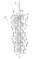
- FIG. 3 is a diagram illustrating an internal configuration example viewed from the side of a general banknote identification device 102X.
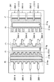
- FIG. 4 is a diagram illustrating an example of a conveyance surface when the lower unit 201 is viewed in the arrow direction A of FIG.
- the bill validator 102 ⁇ / b> X has a conveyance path 251 between the upper unit 200 and the lower unit 201.
- the bill discriminating apparatus 102X has an optical glass 210g that transmits the irradiation light to the bill passing through the transport path 251 and the reflected light from the bill in the reflection sensor 210 of the upper unit 200.
- the resin conveyance part 210m which comprises the conveyance surface of the optical glass 210g and a smooth surface is fitted to the conveyance guide 217 of the upper unit 200.
- the banknote discrimination device 102X has the optical glass 211g which permeate
- a resin transport portion 211m that forms a smooth surface with the transport surface of the optical glass 211g is fitted into the transport guide 218 of the lower unit 201.
- the resin transport portion 211m has a nested shape such as a portion and a bottom portion, and forms a comb-like shape with the transport surface of the lower unit 201.
- the resin conveyance unit 210m has a similar nesting shape, and forms a comb-like shape with the conveyance surface of the upper unit 200. With this configuration, it is possible to prevent the banknote 250 passing through the transport path 251 from entering the boundary between the transport surface of the upper unit 200 and the reflection sensor 210.
- the bill validator 102X has an optical glass 212g that transmits the irradiation light to the bill that passes through the transport path 251 in the transmission sensor light emitting unit 212 of the upper unit 200.
- the resin conveyance part 212m which comprises the conveyance surface of the optical glass 212g and a smooth surface is fitted to the conveyance guide 217 of the upper unit 200.
- the irradiation light is irradiated by the transmission sensor light emitting unit 212.
- the bill validator 102X includes an optical glass 213g that transmits the transmitted light transmitted by the bill passing through the transport path 251 in the transmission sensor light receiving unit 213 of the lower unit 201.
- a resin transport portion 213m that forms a smooth surface with the transport surface of the optical glass 213g is fitted into the transport guide 218 of the lower unit 201.
- the resin conveyance part 212m has the same nesting shape, and forms a comb-tooth shape with the conveyance surface of the upper unit 200. With this configuration, it is possible to prevent the banknote 250 passing through the transport path 251 from entering the boundary between the transport surface of the upper unit 200 and the transmission sensor light emitting unit 212. As shown in FIG. 4, the resin transport unit 213 m has a nested shape such as a part C and a part D, and forms a comb-like shape with the transport surface of the lower unit 201. With this configuration, it is possible to prevent the banknote 250 passing through the transport path 251 from entering the boundary between the transport surface of the lower unit 201 and the transmission sensor light receiving unit 213.
- the bill validator 102X has a magnetic sensor 214 in the lower unit 201 that detects the magnetic properties of the bill passing through the transport path.
- the magnetic sensor 214 is covered with a metal cover 214p (for example, a nonmagnetic thin plate of about 0.2 mm) that forms a smooth surface with the resin transport portion 214m.
- the resin transport unit 214m is fitted into the transport guide 218 of the lower unit 201. As shown in FIG. 4, the resin transport unit 214 m has a nested shape like a ho-part and forms a comb-tooth shape with the transport surface of the lower unit 201. With this configuration, it is possible to prevent the banknote 250 passing through the transport path 251 from entering the boundary between the transport surface of the lower unit 201 and the magnetic sensor 214.
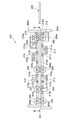
- FIG. 5 is a diagram illustrating an internal configuration example viewed from the side of the bill validating device 102 according to the first embodiment.
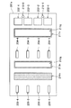
- FIG. 6 is a diagram illustrating an example of a conveyance surface when the lower unit 201a is viewed in the arrow direction B of FIG.
- the bill validator 102 has a conveyance path 251 between the upper unit 200a and the lower unit 200b.
- the conveyance roller 203 is attached to the upper unit 200a so as to be rotatable with respect to the shaft 203a.
- the transport roller 205 is attached to the upper unit 200a so as to be rotatable with respect to the shaft 205a.
- the conveyance roller 204 facing the conveyance roller 203 with the conveyance path 251 interposed therebetween is attached to the lower unit 201a so as to be rotatable with respect to the shaft 204a. Further, the transport roller 206 facing the transport roller 205 across the transport path 251 is attached to the lower unit 201a so as to be rotatable with respect to the shaft 206a.
- the transport roller 203, the transport roller 204, the transport roller 205, and the transport roller 206 transport the banknote 250 that passes through the transport path 251.
- the thickness detection roller 215 is rotatably supported by a roller support bracket 215a, and the roller support bracket 215a is rotatably supported by a shaft 215b and attached to a bracket 215c fixed to the upper unit 200a.
- the roller 202 that faces the thickness detection roller 215 across the conveyance path 251 has a shaft 202a and is attached to the lower unit 201a.
- the upper unit 200 a has a conveyance guide 217 a that forms the conveyance surface of the banknote 250
- the lower unit 201 a has a conveyance guide 218 a that forms the conveyance surface of the banknote 250.
- At least one of the transport guide 217a and the transport guide 218a is provided with a sensor that detects data related to the banknote 250. Data detected by the sensor can be used to determine the denomination, fouling state, authenticity, etc. of the banknote 250.
- the conveyance guide 217a is provided with a reflection sensor 210 and a transmission sensor light emitting unit 212.
- the transport guide 218a is provided with a reflection sensor 211, a transmission sensor light receiving unit 213, and a magnetic sensor 214.
- the roller 207 is attached to the shaft 207a so as to face the magnetic sensor 214 with a slight gap, and is rotatably attached to the lower unit 201a.
- the reflection sensor 210 irradiates the banknote 250 passing through the transport path 251 with light, and detects the light reflected by the banknote 250 as data related to the banknote.
- the reflection sensor 210 includes a glass-integrated resin-molded portion having a glass forming a transport surface of the banknote 250 at the time of data detection and a resin member 210n covering the periphery of the glass. As shown in FIG. 5, when glass is comprised with the optical glass 210g, the optical glass 210g permeate
- the reflection sensor 210 detects the reflected light from the bill 250 transmitted by the optical glass 210g.
- the resin member 210n included in the glass integrated resin molding portion and the conveyance guide 217a are integrally molded. Further, the resin member 210n and the conveyance guide 217a included in the glass integrated resin molding portion form a flat conveyance surface.
- the reflection sensor 211 irradiates the bill 250 passing through the transport path 251 with light, and detects the light reflected by the bill 250 as data related to the bill.
- the reflection sensor 210 includes a glass-integrated resin-molded part having a resin member 211n that covers the periphery of the glass and the glass that forms the conveyance surface of the banknote 250 at the time of data detection. As shown in FIG. 5, when glass is comprised with the optical glass 211g, the optical glass 211g permeate
- the reflection sensor 211 detects the reflected light from the banknote 250 transmitted by the optical glass 211g when the irradiation light transmitted by the optical glass 211g reaches the banknote 250 and is reflected.
- the resin member 211n included in the glass integrated resin molding portion and the conveyance guide 218a are integrally molded. Further, the resin member 211n and the conveyance guide 218a included in the glass integrated resin molding portion form a flat conveyance surface.
- the transmission sensor light emitting unit 212 irradiates the bill 250 passing through the transport path 251 with light, and the transmission sensor light receiving unit 213 detects the light transmitted by the bill 250 as data on the bill.
- the optical glass 212g permeate
- the transmission sensor light emitting unit 212 includes a glass-integrated resin molding unit having a glass forming a transport surface of the banknote 250 at the time of data detection and a resin member 212n covering the periphery of the glass.
- the resin member 212n and the conveyance guide 217a included in the glass integrated resin molding portion are integrally molded. Further, the resin member 212n and the conveyance guide 217a included in the glass integrated resin molding portion form a flat conveyance surface.
- the transmission sensor light receiving unit 213 includes a glass integrated resin molding unit having a glass forming a transport surface of the banknote 250 at the time of data detection and a resin member 213n covering the periphery of the glass. As shown in FIG. 5, when the glass is constituted by the optical glass 213 g, the optical glass 213 g transmits the transmitted light from the banknote 250. At that time, the transmission sensor light receiving unit 213 detects the transmitted light transmitted by the optical glass 213g. More specifically, the transmission sensor light receiving unit 213 detects the transmitted light when the irradiation light from the transmission sensor light emitting unit 212 transmitted by the optical glass 212g passes through the bill 250 and the optical glass 213g.
- the resin member 213n included in the glass integrated resin molding portion and the conveyance guide 218a are integrally molded. Moreover, the resin member 213n and the conveyance guide 218a included in the glass integrated resin molding portion form a flat conveyance surface.
- the magnetic sensor 214 detects magnetic information of the banknote 250 passing through the transport path 251 as data related to the banknote. More specifically, since the ink used for printing the banknote 250 is magnetized, the magnetic sensor 214 detects the magnetic characteristics of the ink as magnetic information.
- the magnetic sensor 214 includes a resin member 214n that forms a conveyance surface of the banknote 250 when magnetic information is detected.
- the resin member 214n and the conveyance guide 218a are integrally molded. Further, the resin member 214n and the conveyance guide 218a form a flat conveyance surface.
- thermoplastic resin material such as liquid crystal polymer having a high fluidity that has a low linear expansion coefficient indicating a thermal expansion coefficient and can be filled in a molding die even at a low pressure is used. It is preferable to be molded integrally with the optical glass 211g. For the same reason, as the resin member 213n, it is preferable to use a thermoplastic resin material and to be molded integrally with the optical glass 213g of the transmission sensor light receiving part 213. Thereby, the possibility that the phenomenon that the optical glass warps due to the shrinkage of the resin and a crack occurs can be reduced.
- the banknotes 250 (or the banknotes 250 carried out from the replenishment collection cassette 108 and the denomination storages 104, 105, 106 in the banknote depositing / dispensing machine 50) inserted by the customer from the deposit / withdrawal port 4 of the cash dispenser 1 are It is conveyed to the banknote identification device 102 through a conveyance path.
- the bill validator 102 rotates the roller 202, the roller 207, the transport roller 204, and the transport roller 206 by a rotation driving mechanism (not shown), thereby transferring the bill 250 being transported to the transport path of the bill validator 102. Pull in.
- the bill validator 102 sends out the bill 250 while detecting data related to the bill by various sensors provided in the transport guide 217a of the upper unit 200a and the transport guide 218a of the lower unit 201a.
- the senor includes the glass integrated resin molding portion, and the resin member and the conveyance guide included in the glass integrated resin molding portion are integrally molded. According to this structure, it becomes possible to improve the conveyance performance of a banknote. Specifically, according to such a configuration, there is no need to have a nesting portion on the conveyance surface, a step that becomes an obstacle to the conveyance of the banknote 250 can be eliminated, and a clogging of the banknote 250 such as a fold is caught on the level difference. The effect which suppresses can be enjoyed.
- thermoplastic resin material such as a liquid crystal polymer having a low linear expansion coefficient among resin molding materials may be integrally molded with the transport guide as a resin member around the optical glass.
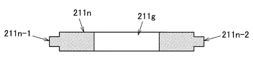
- FIG. 7 is a diagram illustrating a configuration example of the glass-integrated resin molded portion according to the first embodiment.
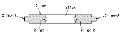
- FIG. 8 is a figure which shows the structural example of the glass integrated resin molding part which concerns on 2nd Embodiment.
- the glass integrated resin molding part of the reflection sensor 211 is mainly demonstrated here, the kind of sensor is not limited to the reflection sensor 211.
- the glass-integrated resin-molded portion according to the first embodiment of the present invention has an optical glass 211g and a resin member 211n covering the periphery of the optical glass 211g, and is transported with the resin member 211n.
- the joint portion with the guide 218a has a structure in which the resin member 211n and the conveyance guide 218a are fitted.
- the resin member 211n has convex portions 211n-1 and 211n-2, and the convex portions 211n-1 and 211n-2 have a structure that fits into the concave portion of the conveyance guide 218a.
- the glass-integrated resin-molded portion according to the second embodiment of the present invention has an optical glass 211gx and a resin member 211nx covering the periphery of the optical glass 211gx.
- the joint between the resin member 211nx and the transport guide 218a has a structure in which the resin member 211nx and the transport guide 218a are fitted.
- the resin member 211nx has convex portions 211nx-1, 211nx-2, and the convex portions 211nx-1, 211nx-2 have a structure that fits into the concave portion of the conveyance guide 218a.
- the joint between the resin member 211nx and the optical glass 211gx has a structure in which the resin member 211nx and the optical glass 211gx are fitted.
- the resin member 211nx has a convex portion
- the convex portions 211gx-1 and 211gx-2 have a structure that fits into the concave portions 211gx-1 and 211gx-2 of the optical glass 211gx.
- recesses 211gx-1 and 211gx-2 are applied to the optical glass 211gx, and then the resin member 211nx and the optical glass 211gx are integrally molded.
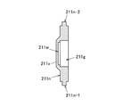
- FIG. 9A and FIG. 9B are diagrams illustrating a configuration example of a glass integrated resin molding unit according to the third embodiment.
- the glass integrated resin molding part of the reflection sensor 211 is mainly demonstrated here, the kind of sensor is not limited to the reflection sensor 211.
- the white reference tape 211w is bonded to the end of the optical glass 211g (for example, one side of the end in the longitudinal direction of the optical glass 211g).
- the reflection sensor 211 includes a holding portion 211v that covers the white reference tape 211w.
- the white reference tape 211w is bonded to the optical glass 211g, and the resin member 211n and the optical glass 211g are integrally molded.
- the end of the holding portion 211v may be inclined.
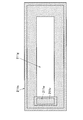
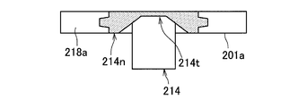
- FIG. 10 is a diagram illustrating an example of a conveyance surface of the magnetic sensor 214 according to the fourth embodiment.
- the magnetic sensor 214 detects the magnetic characteristics of the ink used for printing the banknote 250. Therefore, in order for the magnetic characteristics of the ink to be easily detected by the magnetic sensor 214, it is preferable that the internal elements of the magnetic sensor 214 be brought close to the transport surface of the resin member 214n. Specifically, as shown in FIG. 10, the resin member 214n of the magnetic sensor 214 may have a thin portion 214t formed thinner than the thickness of the transport guide 218a. In this way, since the magnetic sensor may be directly attached to the thin portion 214t, it is not necessary to provide the metal cover 214p, and the number of parts and the assembly procedure can be reduced.
- a highly fluid resin material for example, a liquid crystal polymer having high fluidity
- at least one of the types of resins constituting the resin member 214n is preferably a high fluidity resin material.
- the thickness of the thin portion 214t may be 0.2 mm to 0.5 mm, for example. If a high fluidity resin material is used as the thin portion 214t, the thickness of the thin portion 214t can be 0.2 mm to 0.5 mm.
- the height adjustment work of the conveyance guide 218a in which the magnetic sensor 214 is arranged can be omitted, and the manufacturing efficiency can be realized. Further, since the resin member 214n has the thin portion 214t, the distance between the magnetic sensor 214 and the transport path 251 can be narrowed, and the detection range of the magnetic characteristics can be widened.
- At least one of the types of resins constituting the resin member 214n may be a high-fluidity resin material, but the resin member 214n has two or more different types in the thin-walled portion 214t and other portions.
- the material may be integrally molded. Thereby, it becomes possible to eliminate the conveyance failure by the banknote colliding with a level
- the high-fluidity resin material is often expensive, it is possible to enjoy the effect that the cost can be reduced by suppressing the necessary amount thereof.
- the optical glass and the resin member may be integrally formed after providing a plurality of hole-shaped portions at the end of the optical glass. As described above, even if the optical glass is provided with a plurality of hole-shaped portions, it is possible to realize both the improvement of the bonding strength with the resin member and the securing of the sealing property.
Abstract
Description
まず、本発明の第1の実施形態について説明する。図1は、第1の実施形態に係る現金預払機1の外観を示す斜視図である。図1に示すように、第1の実施形態に係る現金預払機1は、一例として、筐体2と、ディスプレイ3と、入出金口4と、カード挿入返却口5と、通帳挿入返却口6とを備えている。なお、以下の説明においては、現金預払機1に各機構部が収納されている例を示すが、現金預払機1の代わりに他の端末(例えば、現金処理機など)に各機構部が収納されていてもよい。 [Description of First Embodiment]
First, a first embodiment of the present invention will be described. FIG. 1 is a perspective view showing an appearance of a
続いて、本発明の第2の実施形態について説明する。本発明の第2の実施形態は、本発明の第1の実施形態とガラス一体樹脂成型部の構成が異なる。したがって、本発明の第2の実施形態においては、ガラス一体樹脂成型部の構成について主に説明する。図7は、第1の実施形態に係るガラス一体樹脂成型部の構成例を示す図である。一方、図8は、第2の実施形態に係るガラス一体樹脂成型部の構成例を示す図である。なお、ここでは、反射センサ211のガラス一体樹脂成型部について主に説明するが、センサの種類は反射センサ211に限定されない。 [Description of Second Embodiment]
Subsequently, a second embodiment of the present invention will be described. The second embodiment of the present invention is different from the first embodiment of the present invention in the configuration of the glass-integrated resin molded portion. Therefore, in the second embodiment of the present invention, the configuration of the glass-integrated resin molded portion will be mainly described. FIG. 7 is a diagram illustrating a configuration example of the glass-integrated resin molded portion according to the first embodiment. On the other hand, FIG. 8 is a figure which shows the structural example of the glass integrated resin molding part which concerns on 2nd Embodiment. In addition, although the glass integrated resin molding part of the
続いて、本発明の第3の実施形態について説明する。本発明の第3の実施形態は、本発明の第1の実施形態とガラス一体樹脂成型部の構成が異なる。したがって、本発明の第3の実施形態においては、ガラス一体樹脂成型部の構成について主に説明する。図9Aおよび図9Bは、第3の実施形態に係るガラス一体樹脂成型部の構成例を示す図である。なお、ここでは、反射センサ211のガラス一体樹脂成型部について主に説明するが、センサの種類は反射センサ211に限定されない。 [Description of Third Embodiment]
Subsequently, a third embodiment of the present invention will be described. The third embodiment of the present invention is different from the first embodiment of the present invention in the configuration of the glass-integrated resin molded portion. Therefore, in the third embodiment of the present invention, the configuration of the glass-integrated resin molded portion will be mainly described. FIG. 9A and FIG. 9B are diagrams illustrating a configuration example of a glass integrated resin molding unit according to the third embodiment. In addition, although the glass integrated resin molding part of the
続いて、本発明の第4の実施形態について説明する。本発明の第4の実施形態は、本発明の第1の実施形態と磁気センサ214の構成が異なる。したがって、本発明の第4の実施形態においては、磁気センサ214の構成について主に説明する。図10は、第4の実施形態に係る磁気センサ214の搬送面の例を示す図である。 [Description of Fourth Embodiment]
Subsequently, a fourth embodiment of the present invention will be described. The fourth embodiment of the present invention is different from the first embodiment of the present invention in the configuration of the
以上、添付図面を参照しながら本発明の好適な実施形態について詳細に説明したが、本発明はかかる例に限定されない。本発明の属する技術の分野における通常の知識を有する者であれば、請求の範囲に記載された技術的思想の範疇内において、各種の変更例または修正例に想到し得ることは明らかであり、これらについても、当然に本発明の技術的範囲に属するものと了解される。 [Description of modification]
The preferred embodiments of the present invention have been described in detail above with reference to the accompanying drawings, but the present invention is not limited to such examples. It is obvious that a person having ordinary knowledge in the technical field to which the present invention belongs can come up with various changes or modifications within the scope of the technical idea described in the claims. Of course, it is understood that these also belong to the technical scope of the present invention.
Claims (9)
- 紙幣を搬送する搬送ローラと、
前記紙幣の搬送面を形成する搬送ガイドと、
前記紙幣に関するデータを検出するセンサと、
前記データの検出時における前記紙幣の搬送面を形成するガラスおよび当該ガラスの周囲を覆った樹脂部材を有するガラス一体樹脂成型部と、を備え、
前記ガラス一体樹脂成型部が有する樹脂部材と前記搬送ガイドとは一体に成型される、
紙幣鑑別装置。 A transport roller for transporting banknotes;
A conveyance guide that forms a conveyance surface of the banknote;
A sensor for detecting data relating to the banknote;
A glass-integrated resin-molded part having a glass that forms a conveyance surface of the banknote at the time of detection of the data and a resin member that covers the periphery of the glass;
The resin member of the glass-integrated resin molding part and the transport guide are molded integrally.
Banknote discrimination device. - 前記ガラス一体樹脂成型部が有する樹脂部材と前記搬送ガイドとは、平らな搬送面を形成する、
請求項1に記載の紙幣鑑別装置。 The resin member included in the glass-integrated resin molded portion and the transport guide form a flat transport surface.
The bill discriminating apparatus according to claim 1. - 前記ガラス一体樹脂成型部が有する樹脂部材と前記搬送ガイドとの接合部は、前記ガラス一体樹脂成型部が有する樹脂部材と前記搬送ガイドとが嵌合する構造を有する、
請求項1に記載の紙幣鑑別装置。 The joint portion between the resin member included in the glass integrated resin molded portion and the transport guide has a structure in which the resin member included in the glass integrated resin molded portion and the transport guide are fitted.
The bill discriminating apparatus according to claim 1. - 前記ガラス一体樹脂成型部が有する樹脂部材と前記ガラスとの接合部は、前記ガラス一体樹脂成型部が有する樹脂部材と前記ガラスとが嵌合する構造を有する、
請求項1に記載の紙幣鑑別装置。 The joint portion between the glass and the resin member included in the glass integrated resin molded portion has a structure in which the resin member included in the glass integrated resin molded portion and the glass are fitted.
The bill discriminating apparatus according to claim 1. - 前記ガラスの端部に白基準テープが接着され、前記センサは、前記白基準テープを覆う保持部を備える、
請求項1に記載の紙幣鑑別装置。 A white reference tape is bonded to an end of the glass, and the sensor includes a holding unit that covers the white reference tape.
The bill discriminating apparatus according to claim 1. - 前記ガラスは、紙幣への照射光および紙幣からの反射光を透過する光学ガラスを含み、前記センサは、前記光学ガラスによって透過された前記反射光を検出する反射センサを含む、
請求項1に記載の紙幣鑑別装置。 The glass includes an optical glass that transmits irradiation light to the banknote and reflected light from the banknote, and the sensor includes a reflection sensor that detects the reflected light transmitted by the optical glass.
The bill discriminating apparatus according to claim 1. - 前記センサは、前記紙幣を透過した透過光を透過する光学ガラスを含み、前記ガラスは、前記光学ガラスによって透過された前記透過光を検出する透過センサを含む、
請求項1に記載の紙幣鑑別装置。 The sensor includes an optical glass that transmits the transmitted light that has passed through the banknote, and the glass includes a transmission sensor that detects the transmitted light transmitted by the optical glass.
The bill discriminating apparatus according to claim 1. - 前記紙幣鑑別装置は、前記紙幣の磁気情報を検出する磁気センサを含み、前記磁気センサは、前記磁気情報の検出時における前記紙幣の搬送面を形成する樹脂部材を有し、前記紙幣の搬送面を形成する樹脂部材と前記搬送ガイドとは一体に成型される、
請求項1に記載の紙幣鑑別装置。 The banknote discrimination device includes a magnetic sensor that detects magnetic information of the banknote, and the magnetic sensor includes a resin member that forms a transport surface of the banknote when the magnetic information is detected, and the transport surface of the banknote The resin member forming the and the conveyance guide are integrally molded,
The bill discriminating apparatus according to claim 1. - 前記紙幣の搬送面を形成する樹脂部材は、前記搬送ガイドの厚みよりも薄く形成される、
請求項8に記載の紙幣鑑別装置。 The resin member that forms the transport surface of the banknote is formed thinner than the thickness of the transport guide.
The bill discriminating apparatus according to claim 8.
Priority Applications (3)
| Application Number | Priority Date | Filing Date | Title |
|---|---|---|---|
| RU2015154964A RU2632036C1 (en) | 2013-09-30 | 2014-05-19 | Device for discriminating banknotes |
| CN201480030312.5A CN105247581B (en) | 2013-09-30 | 2014-05-19 | Bill discriminating apparatus |
| US14/899,308 US20160148455A1 (en) | 2013-09-30 | 2014-05-19 | Banknote discrimination device |
Applications Claiming Priority (2)
| Application Number | Priority Date | Filing Date | Title |
|---|---|---|---|
| JP2013-203244 | 2013-09-30 | ||
| JP2013203244A JP6079534B2 (en) | 2013-09-30 | 2013-09-30 | Bill discrimination device |
Publications (1)
| Publication Number | Publication Date |
|---|---|
| WO2015045478A1 true WO2015045478A1 (en) | 2015-04-02 |
Family
ID=52742637
Family Applications (1)
| Application Number | Title | Priority Date | Filing Date |
|---|---|---|---|
| PCT/JP2014/063236 WO2015045478A1 (en) | 2013-09-30 | 2014-05-19 | Paper currency sorting device |
Country Status (5)
| Country | Link |
|---|---|
| US (1) | US20160148455A1 (en) |
| JP (1) | JP6079534B2 (en) |
| CN (1) | CN105247581B (en) |
| RU (1) | RU2632036C1 (en) |
| WO (1) | WO2015045478A1 (en) |
Cited By (2)
| Publication number | Priority date | Publication date | Assignee | Title |
|---|---|---|---|---|
| CN107424351A (en) * | 2017-08-22 | 2017-12-01 | 昆山古鳌电子机械有限公司 | A kind of bank note conveying and detection means |
| WO2018139123A1 (en) * | 2017-01-25 | 2018-08-02 | 三菱電機株式会社 | Housing and magnetic sensor device |
Families Citing this family (4)
| Publication number | Priority date | Publication date | Assignee | Title |
|---|---|---|---|---|
| JP6544068B2 (en) * | 2015-06-16 | 2019-07-17 | 沖電気工業株式会社 | Medium discrimination device and automatic transaction device |
| JP6593150B2 (en) * | 2015-12-18 | 2019-10-23 | 沖電気工業株式会社 | Medium discrimination device and automatic transaction device |
| JP6662028B2 (en) * | 2015-12-22 | 2020-03-11 | 沖電気工業株式会社 | Media transport device and media transaction device |
| JP6825418B2 (en) * | 2017-02-24 | 2021-02-03 | 沖電気工業株式会社 | Paper leaf identification device and automated teller machine having the paper leaf identification device |
Citations (5)
| Publication number | Priority date | Publication date | Assignee | Title |
|---|---|---|---|---|
| JPS617155A (en) * | 1984-06-20 | 1986-01-13 | Hitachi Ltd | Paper carrier |
| JPS62173334U (en) * | 1986-04-23 | 1987-11-04 | ||
| JP2000132726A (en) * | 1998-10-23 | 2000-05-12 | Fuji Electric Co Ltd | Paper money discriminating device |
| JP2010214589A (en) * | 2007-07-12 | 2010-09-30 | Agc Matex Co Ltd | Glass-integrated resin molding, and molding method therefor |
| JP2013089178A (en) * | 2011-10-21 | 2013-05-13 | Canon Components Inc | Image sensor unit and image reading device |
Family Cites Families (11)
| Publication number | Priority date | Publication date | Assignee | Title |
|---|---|---|---|---|
| US6748101B1 (en) * | 1995-05-02 | 2004-06-08 | Cummins-Allison Corp. | Automatic currency processing system |
| US6769220B2 (en) * | 1996-02-08 | 2004-08-03 | Charles E. Friesner | Structural member |
| WO2001059685A2 (en) * | 2000-02-08 | 2001-08-16 | Cummins-Allison Corp. | Method and apparatus for detecting doubled bills in a currency handling device |
| TW503646B (en) * | 2000-03-16 | 2002-09-21 | Nippon Sheet Glass Co Ltd | Line illuminating device |
| JP5116133B2 (en) * | 2006-08-22 | 2013-01-09 | 株式会社ユニバーサルエンターテインメント | Banknote handling equipment |
| JP4671932B2 (en) * | 2006-08-22 | 2011-04-20 | 株式会社ユニバーサルエンターテインメント | Banknote handling equipment |
| JP4656658B2 (en) * | 2006-08-22 | 2011-03-23 | 株式会社ユニバーサルエンターテインメント | Banknote handling equipment |
| US7796310B2 (en) * | 2007-10-31 | 2010-09-14 | Canon Denshi Kabushiki Kaisha | Image reading apparatus and control method therefor, as well as storage medium |
| JP2009222853A (en) * | 2008-03-14 | 2009-10-01 | Fujitsu Ltd | Polarizing optical element and manufacturing method therefor |
| WO2012015012A1 (en) * | 2010-07-30 | 2012-02-02 | 三菱電機株式会社 | Magnetic sensor device |
| JP2013106145A (en) * | 2011-11-11 | 2013-05-30 | Fuji Xerox Co Ltd | Reading apparatus |
-
2013
- 2013-09-30 JP JP2013203244A patent/JP6079534B2/en active Active
-
2014
- 2014-05-19 CN CN201480030312.5A patent/CN105247581B/en not_active Expired - Fee Related
- 2014-05-19 US US14/899,308 patent/US20160148455A1/en not_active Abandoned
- 2014-05-19 WO PCT/JP2014/063236 patent/WO2015045478A1/en active Application Filing
- 2014-05-19 RU RU2015154964A patent/RU2632036C1/en active
Patent Citations (5)
| Publication number | Priority date | Publication date | Assignee | Title |
|---|---|---|---|---|
| JPS617155A (en) * | 1984-06-20 | 1986-01-13 | Hitachi Ltd | Paper carrier |
| JPS62173334U (en) * | 1986-04-23 | 1987-11-04 | ||
| JP2000132726A (en) * | 1998-10-23 | 2000-05-12 | Fuji Electric Co Ltd | Paper money discriminating device |
| JP2010214589A (en) * | 2007-07-12 | 2010-09-30 | Agc Matex Co Ltd | Glass-integrated resin molding, and molding method therefor |
| JP2013089178A (en) * | 2011-10-21 | 2013-05-13 | Canon Components Inc | Image sensor unit and image reading device |
Cited By (4)
| Publication number | Priority date | Publication date | Assignee | Title |
|---|---|---|---|---|
| WO2018139123A1 (en) * | 2017-01-25 | 2018-08-02 | 三菱電機株式会社 | Housing and magnetic sensor device |
| JPWO2018139123A1 (en) * | 2017-01-25 | 2019-02-07 | 三菱電機株式会社 | Case and magnetic sensor device |
| US10976382B2 (en) | 2017-01-25 | 2021-04-13 | Mitsubishi Electric Corporation | Housing and magnetic sensor device |
| CN107424351A (en) * | 2017-08-22 | 2017-12-01 | 昆山古鳌电子机械有限公司 | A kind of bank note conveying and detection means |
Also Published As
| Publication number | Publication date |
|---|---|
| US20160148455A1 (en) | 2016-05-26 |
| RU2632036C1 (en) | 2017-10-02 |
| CN105247581B (en) | 2018-05-08 |
| JP2015069424A (en) | 2015-04-13 |
| JP6079534B2 (en) | 2017-02-15 |
| CN105247581A (en) | 2016-01-13 |
Similar Documents
| Publication | Publication Date | Title |
|---|---|---|
| JP6079534B2 (en) | Bill discrimination device | |
| JP5375912B2 (en) | Medium discrimination device and medium transaction device | |
| US7850165B2 (en) | Paper sheet storing apparatus | |
| JP5603259B2 (en) | Paper sheet identification device | |
| US9646447B2 (en) | Determination apparatus and medium transaction apparatus | |
| WO2015174290A1 (en) | Thickness detection device, and medium transaction device | |
| WO2016059839A1 (en) | Medium accommodating device and medium transaction device | |
| JP5605151B2 (en) | Sensor support mechanism and paper sheet handling apparatus using the sensor support mechanism | |
| EP2743894B1 (en) | Counterfeit media detection | |
| WO2016199520A1 (en) | Thickness detection device and medium transaction device | |
| JP6292016B2 (en) | Identification device and medium transaction device | |
| JP6593150B2 (en) | Medium discrimination device and automatic transaction device | |
| KR100961576B1 (en) | Paper media providing device and control method of the same | |
| JP5853717B2 (en) | Thickness detection device | |
| JP6544068B2 (en) | Medium discrimination device and automatic transaction device | |
| JP6241328B2 (en) | Medium accumulation feeding device and banknote transaction device | |
| WO2016194541A1 (en) | Medium identification device and medium handling device | |
| JP2017194849A (en) | Medium identifier and medium handling device having medium identifier mounted thereon | |
| JP5472523B2 (en) | Medium discrimination device and medium transaction device | |
| EP4239604A1 (en) | Paper sheet thickness detection apparatus, paper sheet identification apparatus, and paper sheet handling appartus | |
| JP6825418B2 (en) | Paper leaf identification device and automated teller machine having the paper leaf identification device | |
| KR20110079091A (en) | Cassette and method to sense remainder of paper thereof | |
| JPWO2016031410A1 (en) | Medium transport identification apparatus and medium transaction apparatus | |
| JP6930311B2 (en) | Coin recognition device and coin processing device | |
| JP2017059146A (en) | Thickness detection device and medium transaction device |
Legal Events
| Date | Code | Title | Description |
|---|---|---|---|
| 121 | Ep: the epo has been informed by wipo that ep was designated in this application |
Ref document number: 14848564 Country of ref document: EP Kind code of ref document: A1 |
|
| WWE | Wipo information: entry into national phase |
Ref document number: 14899308 Country of ref document: US |
|
| WWE | Wipo information: entry into national phase |
Ref document number: IDP00201600092 Country of ref document: ID |
|
| REG | Reference to national code |
Ref country code: BR Ref legal event code: B01A Ref document number: 112016000441 Country of ref document: BR |
|
| NENP | Non-entry into the national phase |
Ref country code: DE |
|
| ENP | Entry into the national phase |
Ref document number: 2015154964 Country of ref document: RU Kind code of ref document: A |
|
| 122 | Ep: pct application non-entry in european phase |
Ref document number: 14848564 Country of ref document: EP Kind code of ref document: A1 |
|
| ENP | Entry into the national phase |
Ref document number: 112016000441 Country of ref document: BR Kind code of ref document: A2 Effective date: 20160108 |