WO2015041319A1 - 通信システム、移動局装置及び通信方法 - Google Patents
通信システム、移動局装置及び通信方法 Download PDFInfo
- Publication number
- WO2015041319A1 WO2015041319A1 PCT/JP2014/074836 JP2014074836W WO2015041319A1 WO 2015041319 A1 WO2015041319 A1 WO 2015041319A1 JP 2014074836 W JP2014074836 W JP 2014074836W WO 2015041319 A1 WO2015041319 A1 WO 2015041319A1
- Authority
- WO
- WIPO (PCT)
- Prior art keywords
- base station
- communication
- transmission power
- unit
- terminal
- Prior art date
- Legal status (The legal status is an assumption and is not a legal conclusion. Google has not performed a legal analysis and makes no representation as to the accuracy of the status listed.)
- Ceased
Links
Images




Classifications
-
- H—ELECTRICITY
- H04—ELECTRIC COMMUNICATION TECHNIQUE
- H04W—WIRELESS COMMUNICATION NETWORKS
- H04W52/00—Power management, e.g. Transmission Power Control [TPC] or power classes
- H04W52/04—Transmission power control [TPC]
- H04W52/30—Transmission power control [TPC] using constraints in the total amount of available transmission power
- H04W52/34—TPC management, i.e. sharing limited amount of power among users or channels or data types, e.g. cell loading
- H04W52/346—TPC management, i.e. sharing limited amount of power among users or channels or data types, e.g. cell loading distributing total power among users or channels
-
- H—ELECTRICITY
- H04—ELECTRIC COMMUNICATION TECHNIQUE
- H04W—WIRELESS COMMUNICATION NETWORKS
- H04W52/00—Power management, e.g. Transmission Power Control [TPC] or power classes
- H04W52/04—Transmission power control [TPC]
- H04W52/06—TPC algorithms
- H04W52/14—Separate analysis of uplink or downlink
- H04W52/143—Downlink power control
-
- H—ELECTRICITY
- H04—ELECTRIC COMMUNICATION TECHNIQUE
- H04W—WIRELESS COMMUNICATION NETWORKS
- H04W52/00—Power management, e.g. Transmission Power Control [TPC] or power classes
- H04W52/04—Transmission power control [TPC]
- H04W52/06—TPC algorithms
- H04W52/14—Separate analysis of uplink or downlink
- H04W52/146—Uplink power control
-
- H—ELECTRICITY
- H04—ELECTRIC COMMUNICATION TECHNIQUE
- H04W—WIRELESS COMMUNICATION NETWORKS
- H04W52/00—Power management, e.g. Transmission Power Control [TPC] or power classes
- H04W52/04—Transmission power control [TPC]
- H04W52/18—TPC being performed according to specific parameters
- H04W52/22—TPC being performed according to specific parameters taking into account previous information or commands
- H04W52/225—Calculation of statistics, e.g. average or variance
-
- H—ELECTRICITY
- H04—ELECTRIC COMMUNICATION TECHNIQUE
- H04W—WIRELESS COMMUNICATION NETWORKS
- H04W52/00—Power management, e.g. Transmission Power Control [TPC] or power classes
- H04W52/04—Transmission power control [TPC]
- H04W52/30—Transmission power control [TPC] using constraints in the total amount of available transmission power
- H04W52/34—TPC management, i.e. sharing limited amount of power among users or channels or data types, e.g. cell loading
Definitions
- the present invention relates to a communication system, a mobile station apparatus, and a communication method.
- This application claims priority based on Japanese Patent Application No. 2013-195853 filed in Japan on September 20, 2013, the contents of which are incorporated herein by reference.
- CA Carrier Aggregation
- CA Carrier Aggregation
- Non-Patent Document 1 a dual connection in which the terminal communicates with both the macro base station and the small base station in the uplink has been studied.
- the terminal performs CA on the uplink with respect to the macro base station and the small base station (inter site) CA).
- the macro base station and the small base station perform independent uplink schedule control (for example, Non-Patent Document 1).
- the respective base stations may perform uplink resource allocation almost simultaneously.
- the uplink resource allocation is performed such that the uplink transmission power of the terminal exceeds the maximum value. That is, in the communication system, it may be difficult to manage the transmission power of the terminal.
- One embodiment of the present invention provides a communication system, a mobile station apparatus, and a communication method that can manage transmission power of a terminal.
- One aspect of the present invention is a communication system including first and second base station apparatuses and a mobile station apparatus, and the mobile station apparatus is connected to the first base station apparatus, The first communication performed using the first frequency band and the second communication performed using the second frequency band different from the first frequency band between the second base station and the first communication. And the first transmission power based on the first transmission power used in the first communication and the second transmission power used in the second communication. And a control unit that adjusts.
- the transmission power of the terminal can be managed.
- FIG. 1 is a conceptual diagram showing a communication system 100 according to an embodiment of the present invention.
- the communication system 100 includes a macro base station a1-0, a small base station (also referred to as a pico base station) a1-1, a1-2, a1-3, a1-4, a1-5, and a terminal b1.
- the terminal b1 is, for example, a mobile station device such as a mobile phone device or a tablet terminal device.
- FIG. 1 shows base stations a1-0, a1-1, a1-2, a1-3, a1-4, a1-5 and a terminal b1 in the LTE communication system 100.
- Ellipses C10, C11, C12, C13, C14, and C15 in FIG. 1 indicate cell ranges (communications) of the respective base stations a1-0, a1-1, a1-2, a1-3, a1-4, and a1-5. Range).
- the cell C10 is a macro cell.
- the cells C11 to C15 are small cells. Small cells have a smaller cell range than macro cells. Part or all of the small cell range may overlap with the macro cell range.
- FIG. 1 shows the case where the number of base stations and their cell ranges is six, but the number of base stations and their cell ranges may be other than six.
- a terminal b1 includes a macro base station a1-0 and small base stations a1-1, a1-2, a1-3, a1-4, a1-5, and one component carrier (CC: Component).
- Carrier aggregation (CA: Carrier Aggregation) is performed using Carrier.
- CA Carrier Aggregation
- the uplink is communication from the terminal b1 to the base stations a1-0, a1-1, a1-2, a1-3, a1-4, a1-5.
- the downlink is communication from the base stations a1-0, a1-1, a1-2, a1-3, a1-4, a1-5 to the terminal b1.
- a terminal b1 communicates with a macro base station a1-0 using a CC with a bandwidth of 20 MHz in a frequency band (band) A.
- the terminal b1 and the macro base station a1-0 perform communication of control signals and data signals in both uplink and downlink.
- the uplink control signal is arranged in a physical uplink control channel (PUCCH; Physical Uplink Control Channel).
- the uplink data signal is arranged in a physical uplink shared channel (PUSCH; Physical Uplink Shared Channel).
- the downlink control signal is arranged on a physical downlink control channel (PDCCH), and the downlink data signal is arranged on a physical downlink shared channel (PUCCH).
- PUCCH Physical Uplink Control Channel
- PUSCH Physical Uplink Shared Channel
- the base stations a1-0, a1-1, a1-2, a1-3, a1-4, a1-5 are connected to each other through, for example, an X interface via a backhaul.
- the base stations a1-0, a1-1, a1-2, a1-3, a1-4, and a1-5 can directly communicate with each other.
- the macro base station a1-0 and the small base station a1-1 can communicate directly.
- the communication system 100 also includes a core network management device 200.
- the management apparatus 200 and the base stations a1-0, a1-1, a1-2, a1-3, a1-4, a1-5 can communicate.
- the communication system 100 includes the base stations a1-0, a1-1, a1-2, a1-3, a1-4, a1-5, and the terminal b1.
- the terminal b1 simultaneously performs communication with each of a plurality of base stations among the base stations a1-0, a1-1, a1-2, a1-3, a1-4, and a1-5 using different CCs. be able to.
- the terminal b1 distributes transmission power used in each communication based on transmission power in a plurality of communications. For example, the terminal b1 communicates with the macro base station a1-0 using the CC of the frequency band A1 and communication C2 with the macro base station a1-1 using the CC of the frequency band B different from the frequency band A. Can be performed simultaneously.
- the terminal b1 distributes the transmission power communicated by the communication C1 and the transmission power communicated by the communication C2 based on the total transmission power communicated by the communication C1 and the communication C2. Thereby, in the communication system 100, the transmission power of the terminal b1 can be managed.
- the frequency band is an available frequency band defined by the system.
- the frequency band A is a 2 GHz band
- the frequency band B is a 3.5 GHz band.
- the frequency band includes one or more CCs.
- FIG. 2 is a block diagram showing a schematic configuration of the communication system 100 (FIG. 1) according to the embodiment of the present invention.
- FIG. 2 shows the configurations of the base stations a1-0, a1-1, a1-2, a1-3, a1-4, a1-5 and the configuration of the terminal b1.
- the base station a1-0 includes a communication unit a11, a storage unit a12, a control unit a13, a downlink transmission unit a14, and an uplink reception unit a15. Note that the configurations of the base stations a1-1, a1-2, a1-3, a1-4, and a1-5 are the same as the configuration of the base station a1-0, and thus the description thereof is omitted.
- the communication unit a11 communicates with the management apparatus 200 of the core network and other base stations via the backhaul.
- the storage unit a12 stores information acquired by the control unit a13 and information generated by the control unit a13.
- the control unit a13 controls each unit of the base stations a1-0, a1-1, a1-2, a1-3, a1-4, a1-5. For example, the control unit a13 performs processing of received data and transmission data, carrier frequency control of each transmitting / receiving unit, and the like, such as base stations a1-0, a1-1, a1-2, a1-3, a1-4, a1-5. Various controls related to communication.
- the control unit a13 includes an information acquisition unit a131, an allocation unit a132, and an information provision unit a133.
- the information acquisition unit a131 acquires information. For example, the information acquisition unit a131 acquires information from the management apparatus 200 or another base station a1-m via the communication unit a11.
- the information acquisition unit a131 acquires information from the terminal b1 via the uplink reception unit a15.
- This information may include, for example, communication quality information (for example, a channel quality indicator (CQI), a power headroom (PHR) report, etc.) received from the terminal b1.
- the allocation unit a132 allocates resources (frequency band and time band; for example, resource block) used for wireless communication with the terminal b1 based on the information acquired by the information acquisition unit a131.
- the allocation unit a132 generates resource allocation information indicating the allocated resource.
- the information providing unit a133 provides information.
- the information providing unit a133 provides information generated by the control unit a13, information acquired by the information acquisition unit a131, information stored in the storage unit a12, and the like to the terminal a1 via the downlink transmission unit a14.
- This information includes, for example, resource allocation information generated by the allocation unit a132, information acquired from the base station a1-m, and the like.
- the downlink transmission unit a14 transmits the information input from the control unit a13 to the terminal b1 via the antenna.
- the downlink transmission unit a14 includes a first downlink transmission unit a141 and a first downlink transmission unit a142.
- FIG. 2 the case where the downlink transmission unit a14 includes the first downlink transmission unit a141 and the second downlink transmission unit a142 is shown, but a larger number of downlink transmission units (for example, third downlink transmission units). May be provided.
- the first downlink transmission unit a141 and the second downlink transmission unit a142 are provided for each frequency band, and transmit signals using the frequency bands associated with the first downlink transmission unit a141 and the second downlink transmission unit a142.
- the uplink reception unit a15 outputs information received from the terminal b1 via the antenna to the control unit a13.
- the uplink reception unit a15 includes a first uplink reception unit a151 and a first uplink reception unit a152.
- the uplink reception unit a15 includes the first uplink reception unit a151 and the second uplink reception unit a152.
- an uplink reception unit (for example, the third uplink reception unit) more than that is shown. May be provided.
- the first uplink reception unit a151 and the second uplink reception unit a152 are provided for each frequency band, and receive signals using the frequency bands associated with the first uplink reception unit a151 and the second uplink reception unit a152. It may be used when
- the terminal b1 includes an input unit b11, an output unit b12, a storage unit b13, a control unit b14, a downlink reception unit b15, and an uplink transmission unit b16.
- the input unit b11 is a button, a microphone, or the like, and accepts a user operation or voice input.
- the output unit b12 is a display, a speaker, or the like, and outputs information generated by the control unit b14 by display or sound.
- the storage unit b13 stores information acquired by the control unit b14 and information generated by the control unit b14.
- the control part b14 controls each part of the terminal b1.
- the control unit b14 performs various controls related to terminal communication, such as processing of received data and transmission data, and carrier frequency control of each transmitting / receiving unit.
- the control unit b14 includes a power information acquisition unit b141, an information processing unit b142, an adjustment unit b143, and an arrangement control unit b144.
- the power information acquisition unit b141 acquires information indicating the transmission power communicated by the uplink transmission unit b16.
- the power information acquisition unit b141 provides information indicating transmission power in each communication for communication with each of the base stations a1-0, a1-1, a1-2, a1-3, a1-4, and a1-5. get.
- the power information acquisition unit b141 includes information indicating a base station with which each unit communicates for each of the first uplink transmission unit b161 and the second uplink transmission unit b162, that is, for example, for each frequency band or antenna. Information indicating transmission power in communication of each unit may be acquired.
- the power information acquisition unit b141 may acquire, for each CC, information indicating a base station that uses the CC for communication and information indicating transmission power in communication of each CC.
- the information processing unit b142 acquires information. For example, the information processing unit b142 acquires information indicating a user operation or voice input from the input unit b11. The information processing unit b142 acquires information from the base station via the downlink receiving unit b15. This information includes, for example, resource allocation information received from the base station. The information processing unit b142 provides information. For example, the information processing unit b142 provides information generated by the information processing unit b142, acquired information, information stored in the storage unit b13, and the like to the base station via the uplink transmission unit b16. This information includes, for example, communication quality information (for example, CQI) generated by the information processing unit b142.
- communication quality information for example, CQI
- the adjustment unit b143 adjusts the transmission power communicated by the uplink transmission unit b16 based on the information acquired by the power information acquisition unit b141 and the information input from the information processing unit b142.
- the adjustment unit b143 adjusts the transmission power in each communication for each communication of the base stations a1-0, a1-1, a1-2, a1-3, a1-4, a1-5.
- the adjustment unit b143 may adjust the transmission power in communication of each unit for each of the first uplink transmission unit b161 and the second uplink transmission unit b162, that is, for example, for each frequency band or antenna.
- the adjustment part b143 may adjust the transmission power in communication of each CC for every CC.
- the adjustment unit b143 may adjust the transmission power of each communication by adjusting the amplitude of the signal (changing a digital value or a modulation method) or adjusting the arrangement by the arrangement control unit b144.
- the adjustment unit b143 may adjust the transmission power of each communication by adjusting the amplifier (amplification circuit) of the uplink transmission unit b16.
- the arrangement control unit b144 controls the arrangement of signals in communication with the base station based on the information generated by the information processing unit b142 and the acquired information (for example, resource allocation information).
- the downlink receiving unit b15 outputs information received from the base station via the antenna to the control unit b14.
- the downlink receiving unit b15 includes a first downlink receiving unit b151 and a second downlink receiving unit b152.
- FIG. 2 the case where the downlink transmission unit b15 includes the first downlink transmission unit b151 and the second downlink transmission unit b152 is shown, but a larger number of downlink transmission units (for example, third downlink transmission units). May be provided.
- the first downlink receiving unit b151 and the second downlink receiving unit b152 are provided for each frequency band, and receive signals using the frequency bands associated with the first downlink transmitting unit b151 and the second downlink transmitting unit b152.
- the uplink transmission unit b16 transmits the information input from the control unit b14 to the base station via the antenna.
- the uplink transmission unit b16 includes a first uplink transmission unit b161 and a second uplink transmission unit b162.
- FIG. 2 shows the case where the uplink receiving unit b16 includes the first uplink receiving unit b161 and the second uplink receiving unit b162, but more uplink receiving units (for example, third uplink receiving units). May be provided.
- the first uplink transmission unit b161 and the second uplink transmission unit b162 are provided for each frequency band, and transmit signals using the frequency bands associated with the first uplink reception unit b161 and the second uplink reception unit b162. It may be used when
- the transmission power refers to transmission power in uplink communication.
- the terminal b1 controls transmission power for communication by uplink transmission.
- the transmission power may be an average value of transmission power or a maximum value. Further, the transmission power may be a reference power that becomes a reference of transmission power for a signal or an amplifier.
- a conceptual diagram showing the communication system 100 and a block diagram showing a schematic configuration of each base station and terminal of the communication system 100 are the same as those in FIG. 1 and FIG.
- the first embodiment is an example in which resource allocation exceeding the maximum transmission power of the terminal b1 is instructed in the uplink from the terminal b1 to the base station.
- the terminal b1 performs resource allocation after equally reducing the power of each uplink.
- the base stations a1-0, a1-1, a1-2, a1-3, a1-4, a1-5 allocate resources for the terminal b1 independently.
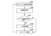
- FIG. 3 is a flowchart showing the operation of the terminal b1 according to the first embodiment of the present invention.
- the information processing unit b142 acquires the first resource allocation information from the macro base station a1-0, and each small base station a1-1, a1-2, a1-3, a1-4, a1-5 To obtain second to sixth resource allocation information.
- the resource of frequency band A (identification number “1”) is allocated to the terminal b1.
- the resource of frequency band B (identification number “2”) is allocated to the terminal b1.
- the terminal b1 is instructed to allocate resources. Then, it progresses to step S102.
- the power information acquisition unit b141 transmits information indicating transmission power in communication with the macro base station a1-0, and the small base stations a1-1, a1-2, a1-3, a1-4, a1- Information indicating the transmission power in the communication with. These transmission powers may be transmission powers that are actually communicating, or may be transmission powers calculated from resource allocation information.
- the information processing unit b142 calculates the total transmission power Pi in all communications based on the information acquired by the power information acquisition unit b141. For example, the information processing unit b142 transmits power in communication with the macro base station a1-0 and transmission in communication with each small base station a1-1, a1-2, a1-3, a1-4, a1-5. The power is added to calculate the total Pi after the addition.
- Step S103 The information processing unit b142 determines whether or not the total Pi calculated in step S102 is larger than a threshold stored in the storage unit b13. This threshold is the maximum transmission power that is the maximum value of the transmission power that can be transmitted by the terminal b1. As a result, the information processing unit b142 exceeds the maximum transmission power of the terminal b1 from the macro base station a1-0 and each of the small base stations a1-1, a1-2, a1-3, a1-4, a1-5. It is determined whether resource allocation is instructed. When it is determined that resource allocation exceeding the maximum transmission power of the terminal b1 is instructed (Yes), the process proceeds to step S104.
- the process proceeds to step S105.
- the maximum transmission power is, for example, the maximum transmission power determined for each terminal b1 described in the 3GPP specifications, and is the maximum transmission power that can be transmitted by the terminal b1. For example, in the terminal b1, the average value of the transmission power in a certain section (for example, time) must not exceed the maximum transmission power.
- Step S104 The adjustment unit b143 uses the first resource allocation information acquired in Step S101 and the resource allocation in the small base stations a1-1, a1-2, a1-3, a1-4, a1-5. Based on a plurality of pieces of resource allocation information among the information, the total transmission power when signals are allocated to the allocated resources is calculated. As a result of the calculation, the adjustment unit b 143 reduces the transmission power by the transmission power that exceeds the maximum transmission power.
- the adjustment unit b143 does not change the transmission power of the uplink control signal, and changes the transmission power of the uplink data signal to each of the base stations a1-0, a1-1, a1-2, a1-3, a1- 4. Reduce evenly with a1-5.
- the adjustment unit b 143 reduces the transmission power to each of the base stations a1-0, a1-1, a1-2, a1-3, a1-4, a1-5 by the same power.
- the adjusting unit b 143 has the base stations a1-0, a1-1, a1-2, a1-3, a1-4, and a1-5 for power corresponding to the frequency band or CC bandwidth and frequency.
- the transmission power may be reduced, or communication of radio management control signals such as handover control
- the transmission power of CCs other than the CC performing the transmission may be reduced.
- the arrangement control unit b144 arranges a signal in the resource based on the first resource allocation information and the second to sixth resource allocation information acquired in Step S101.
- the arrangement control unit b144 arranges the signal in the resource so that the adjusted transmission power is obtained.
- the control unit b14 transmits uplinks from the terminal b1 to the base stations a1-0, a1-1, a1-2, a1-3, a1-4, a1-5.
- the transmission power used in each communication is distributed so that the total transmission power in all communications is equal to or less than a threshold value (maximum transmission power).
- the terminal b1 can prevent the resource arrangement that exceeds the maximum value of the transmission power, and can appropriately manage the transmission power.
- the control unit b14 acquires resource allocation information for communication with the base station from each of the base stations a1-0, a1-1, a1-2, a1-3, a1-4, and a1-5.
- the control unit b14 estimates the transmission power used in each communication based on the resource allocation information, and is a correction value obtained by reducing the fixed value ⁇ P from each estimated transmission power, and the sum of the correction values in all communication is a threshold value. The following correction value is calculated.
- the control unit b14 distributes each calculated correction value as transmission power used in each communication. Thereby, in the communication system 100, the terminal b1 can reduce transmission power uniformly by all the communications.
- the second embodiment is an example in which resource allocation exceeding the maximum transmission power of the terminal b1 is instructed in the uplink from the terminal b1 to the base station.
- the terminal b1 selects a base station, performs communication with the selected base station, and stops communication with the base station that has not been selected.
- each base station a1-0, a1-1, a1-2, a1-3, a1-4, a1-5 independently allocates resources used for radio communication to the terminal b1. .
- FIG. 4 is a flowchart showing the operation of the terminal b1 according to the second embodiment of the present invention.
- the flowchart according to the second embodiment differs from the flowchart according to the first embodiment (FIG. 3) in steps S204 and S205. Since the processing of other steps is the same as that of the flowchart according to the first embodiment, description thereof will be omitted.
- the adjustment unit b143 selects the following (1a) to (1) from the base stations a1-0, a1-1, a1-2, a1-3, a1-4, and a1-5 that are scheduled to perform communication. As in 3a), one or more base stations are selected from the base stations a-0, a1-1, a1-2, a1-3, a1-4, and a1-5.
- the adjustment unit b143 adjusts the base stations a1-0, a1-1, a1-2, a1-3 so that the total transmission power of communication with the selected one or more base stations is less than or equal to the threshold value.
- A1-4, a1-5 one or more base stations are selected.
- This threshold is, for example, the maximum transmission power that is the maximum value of the transmission power of the terminal b1.
- the adjustment unit b143 prioritizes base stations with low transmission power based on the first resource allocation information and the second to sixth resource allocation information acquired in step S101. To select.
- the adjustment unit b143 preferentially selects a base station with good communication quality based on the communication quality information generated by the information processing unit b142.
- the adjustment unit b143 is information acquired by the information processing unit b142, and each base station a1-0, a1-1, a1-2, a1-3, a1-4, a1- A small base station is selected based on information indicating a type of 5 (whether it is a small base station or a macro base station). Thereby, since the small base station a1-i normally has lower transmission power than the macro base station a1-0, the adjustment unit b143 selects a lower base station.
- Step S205 The arrangement control unit b144 arranges a signal in the resource based on the first resource allocation information and the second to sixth resource allocation information acquired in Step S101.
- the arrangement control unit b144 arranges a signal in the resource based on the resource allocation information of the selected base station.
- the control unit b14 when the total transmission power in all communications exceeds the threshold, the base stations a1-0, a1-1, a1-2, a1-3, a1 -4, a1-5, communication with at least one base station is stopped.
- the terminal b1 can prevent resource allocation exceeding the maximum value of transmission power by not arranging resources for communication with a certain base station, and can manage transmission power appropriately.
- the information processing unit b142 cannot place a signal on an uplink resource for a base station that is not selected in step S204, from among base stations scheduled to perform communication. That is, it may be notified that communication is not performed.
- the third embodiment is an example in which resource allocation exceeding the maximum transmission power of the terminal b1 is instructed in the uplink from the terminal b1 to the base station.
- the terminal b1 selects a base station, performs communication with the selected base station, and stops communication with the base station that has not been selected.
- the terminal b1 selects the base station according to the priority order indicated by the stored information. This priority is information indicating the priority notified from the base station, or information indicating a predetermined priority.
- each base station a1-0, a1-1, a1-2, a1-3, a1-4, a1-5 independently allocates resources used for radio communication to the terminal b1. .
- FIG. 5 is a flowchart showing the operation of the terminal b1 according to the third embodiment of the present invention.
- the flowchart according to the third embodiment differs from the flowchart according to the first embodiment (FIG. 3) in steps S300 and S304 to S306. Since the processing of other steps is the same as that of the flowchart according to the first embodiment, description thereof will be omitted.
- Step S300 The information processing unit b142 receives each of the base stations a1-0, a1-1, a1-2, a1-3, a1-4, a1-5 from the base station (for example, the macro base station a1-0). Information indicating the priority order of the communication is acquired. The information processing unit b142 stores the acquired information in the storage unit b13. Then, it progresses to step SS101. (Step S304) The adjusting unit b143 selects the base stations a1-0, a1-1, a1-2, a1-3 according to the priority order indicated by the information stored in step S300 among the base stations scheduled to perform communication. , A1-4, a1-5, one or more base stations are selected.
- the adjustment unit b143 selects one or more base stations so that the total transmission power of communication with the selected one or more base stations is equal to or less than a threshold value.
- This threshold is, for example, the maximum transmission power that is the maximum value of the transmission power of the terminal b1. Thereafter, the process proceeds to step S305.
- Step S305 The information processing unit b142 indicates that a signal cannot be allocated to the uplink resource from the base stations scheduled to perform communication to the base station not selected in Step S304, that is, performs communication. Notify that there is not. Thereafter, the process proceeds to step S306.
- Step S306 The arrangement controller b144 arranges a signal in the resource based on the first resource allocation information and the second to sixth resource allocation information acquired in Step S101. Here, when a base station is selected in step S305, the arrangement control unit b144 arranges a signal in the resource based on the resource allocation information of the selected base station.
- the control unit b14 determines that the base stations a1-0, a1-1, a1-2, a1 according to the priority order. ⁇ 3, a1-4, and a1-5, communication with at least one base station is stopped.
- the terminal b1 can prevent the resource allocation exceeding the maximum value of the transmission power by not allocating the resource to the communication with the base station having a low priority, and can appropriately manage the transmission power.
- the fourth embodiment of the present invention will be described in detail.
- the conceptual diagram showing the communication system 100 and the block diagram showing the schematic configuration of the communication system 100 are the same as those in FIGS.
- the base station or the management apparatus 200 instructs resource allocation so as not to exceed the maximum transmission power of the terminal b1.
- the network side device (base station or management device 200) and the terminal b1 and each of the base stations a1-0, a1-1, a1-2, a1-3, a1- 4 distribution of maximum transmission power is determined for communication a1-5.
- the terminal b1 transmits the PHR for the distributed maximum transmission power to each of the base stations a1-0, a1-1, a1-2, a1-3, a1-4, a1-5. 0, a1-1, a1-2, a1-3, a1-4, a1-5 are reported independently.
- the base station allocates resources based on this report, thereby controlling the transmission power at the terminal b1.
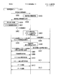
- FIG. 6 is a sequence diagram showing an operation of the communication system 100 according to the fourth embodiment of the present invention.
- the sequence diagram shown in FIG. 6 shows a case where the terminal b1 performs CA with the macro base station a1-0 and one or a plurality of small base stations a1-i.
- Step S401 The terminal b1 is in a standby state.
- the information processing unit b142 When data communication becomes necessary due to a user operation, an application function, or the like, the information processing unit b142 generates a data connection request for requesting connection for data communication. Thereafter, the process proceeds to step S402.
- Step S402 The information processing unit b142 transmits the data connection request generated in step S401 to the macro base station a1-0. Thereafter, the process proceeds to step S403.
- Step S403 The information acquisition unit a131 acquires the data connection request in step S402.
- the allocation unit a132 determines to perform CA, for example, with the macro base station a1-0 and one or a plurality of small base stations a1-i in the uplink.
- each of one or a plurality of small base stations a1-i that perform CA with the macro base station a1-0 for the terminal b1 is referred to as a CA small base station.
- the process proceeds to step S404.
- Step S404 The information providing unit a133 transmits a CA connection notification indicating that CA is performed with the macro base station a1-0 to the terminal b1 to the CA small base station determined in Step S403.
- Step S405. The information providing unit a133 transmits, to the terminal b1, the macro base station a1-0, the CA small base station determined in step S403, and a CA connection setting request for requesting connection setting at the CA in the uplink. . Thereafter, the process proceeds to step S406.
- Step S406 The allocating unit a132 determines the transmission power used for each communication of the macro base station a1-0 and the CA small base station for the terminal b1. For example, the allocation unit a132 determines the maximum transmission power at the terminal b1 in each communication with the macro base station a1-0 and the CA small base station. The allocation unit a132 determines the maximum transmission power in each communication by distributing the transmission power, for example, as in the following (1b) to (3b). Thereafter, the process proceeds to step S407.
- the allocation unit a132 determines the maximum transmission power based on the positional relationship between the macro base station a1-0 where the terminal b1 is located and the CA small base station. For example, the macro base station a1-0 knows the positional relationship with the CA small base station, and sets the distance ratio between the terminal b1 and the macro base station a1-0 and between the terminal b1 and the CA small base station. calculate. The allocation unit a132 determines the maximum power distribution according to these distance ratios. For example, the assigning unit a132 grasps the distance between the macro base station a1-0 and the CA small base station and the small cell radius of the CA small base station from the information stored in the storage unit a12, and the ratio thereof is described above. It is good also as a distance ratio.
- the maximum transmission power of the small base station a1-i is preset (max_Psmall) and stored in the storage unit a12.
- the allocation unit a132 sets the maximum transmission power of the CA small base station as the maximum transmission power set in the storage unit a12.
- the allocation unit a132 sets the maximum transmission power of the macro base station a1-0 to a value obtained by subtracting the sum of the maximum transmission power (max_Psmall) of the CA small base station from the maximum transmission power of the terminal b1.
- the allocation unit a132 distributes equally to the macro base station a1-0 and the CA small base station.
- Step S407 The information providing unit a133 transmits a base station maximum transmission power notification indicating the maximum transmission power determined in step S406 to the CA small base station.
- the base station maximum transmission power notification includes the identification information of the terminal b1 and the maximum transmission power at the CA small base station that is the notification destination for the terminal b1.
- the process proceeds to step S408.
- Step S408 The information providing unit a133 transmits a maximum transmission power notification indicating the maximum transmission power determined in step S406 to the terminal b1.
- the maximum transmission power notification includes identification information of the macro base station a1-0 and the CA small base station, and information indicating the maximum transmission power of each communication with these base stations. Thereafter, the process proceeds to step S409.
- Step S409 The information processing unit b142 acquires the maximum transmission power notification of step S408 and stores it in the storage unit b13.
- the information processing unit b142 transmits a CA connection setting response to the macro base station a1-0. Thereafter, the process proceeds to step S410.
- the adjustment unit b143 estimates transmission power (referred to as PUS transmission power) for transmitting a physical UL shared channel (PUSCH) within a subframe.
- the adjustment unit b143 estimates the maximum transmission power indicated by the maximum transmission power notification in step S408 for each of the base stations a1-0, a1-1, a1-2, a1-3, a1-4, and a1-5.
- the difference from the PUS transmission power is calculated as PHR. That is, the adjustment unit b143 calculates the PHR for the maximum transmission power notification allocated to each of the base stations a1-0, a1-1, a1-2, a1-3, a1-4, a1-5.
- the adjustment unit b143 generates a PHR report indicating the calculated difference.
- the adjustment unit b143 generates a PHR report for communication with the macro base station a1-0.
- the adjustment unit b143 transmits the generated PHR report to the macro base station a1-0. Thereafter, the process proceeds to step S411.
- Step S411 The adjustment unit b143 generates a PHR report for each communication with the CA small base station.
- the adjustment unit b143 transmits the generated power headroom report to each CA small base station. Thereafter, the process proceeds to step S412.
- Step S412 The allocation unit a132 of the macro base station a1-0 allocates resources for communication with the terminal b1, and generates resource allocation information indicating the allocated resources.
- this allocation part a132 allocates a resource based on the PHR report of step S410.
- Arrangement controller b144 controls the arrangement of signals in communication with macro base station a1-0 based on the resource allocation information generated by allocation unit a132 of macro base station a1-0.
- the terminal b1 communicates with the macro base station a1-0 while allocating the transmission used by the arrangement control unit b144 for each communication. Thereafter, the process proceeds to step S413.
- the allocation unit a132 may allocate resources based not only on the PHR report but also on the propagation quality, the remaining data amount of the terminal (terminal data buffer status), and the like.
- the allocation unit a132 of the CA small base station allocates resources for communication with the terminal b1, and generates resource allocation information indicating the allocated resources.
- the allocation unit a132 allocates resources based on the PHR report in step S411.
- the arrangement control unit b144 controls the arrangement of signals in communication with the CA small base station based on the resource allocation information generated by the CA small base station allocation unit a132. Thereby, the terminal b1 communicates with the CA small base station while allocating the electric power used by the arrangement control unit b144 in each communication.
- step S412 and step S413 are repeated, you may return to step S410 or step S411.
- the maximum transmission power of each base station can be changed by reporting the amount of communication data or PHR, and may be reported again when changing.
- the PHR report may be reported as needed when there is a change in path loss. This report is independent for each of the base stations a1-0, a1-1, a1-2, a1-3, a1-4, a1-5, and the terminal b1 is the only base station that needs to be reported. You may report to
- the control unit a13 of the macro base station a1-0 includes the base stations a1-0, a1-1, a1-2, a1-3, a1-4, and a1-5.
- the distribution of the maximum transmission power in each communication of the terminal b1 is determined.
- the control unit b14 determines the transmission power for the resources allocated to the base stations a1-0, a1-1, a1-2, a1-3, a1-4, a1-5 and the maximum transmission power determined by the control unit a13.
- the control unit b14 Based on the allocation, generate a PHR report for each base station a1-0, a1-1, a1-2, a1-3, a1-4, a1-5, and generate the generated PHR report for each base station a1-0, Report to a1-1, a1-2, a1-3, a1-4, a1-5.
- the control unit b14 distributes transmission power for communication in each of the base stations a1-0, a1-1, a1-2, a1-3, a1-4, a1-5. Thereby, in the communication system 100, it is possible to prevent a device on the network side from instructing resource allocation exceeding the maximum transmission power.
- the terminal b1 reports the PHR to the base stations a1-0, a1-1, a1-2, a1-3, a1-4, a1-5, so that the base stations a1-0, a1-1, a1 -2, a1-3, a1-4, and a1-5 can be efficiently scheduled.
- the conceptual diagram showing the communication system 100 and the block diagram showing the schematic configuration of the communication system 100 are the same as those in FIGS.
- the fifth embodiment is an example in which at least one of the maximum transmission powers for each frequency band is different as the terminal capability of the terminal b1.
- FIG. 7 is a sequence diagram showing an operation of the communication system 100 according to the fifth embodiment of the present invention.
- the sequence diagram according to the fifth embodiment differs from the sequence diagram according to the sixth embodiment (FIG. 6) in steps S501 to S506. Since the processing of other steps is the same as that of the flowchart according to the first embodiment, description thereof will be omitted.
- Step S501 The terminal b1 is powered on (power on). Thereafter, the process proceeds to step S502.
- Step S502 The information processing unit b142 reads the terminal capability information stored in advance in the storage unit b13, and transmits a terminal capability information notification (eg, UE Capability message) including the terminal capability information to the macro base station a1-0. .
- This terminal capability information is information indicating the capability of the terminal b1.
- the terminal capability information includes, for example, information indicating the maximum transmission power of the terminal b1 for each frequency band. Thereafter, the process proceeds to step S502.
- the maximum transmission power in the frequency band used for communication with the small base station a1-i may be set lower than the maximum transmission power in the frequency band used for communication with the macro base station a1-0. .
- the maximum transmission power for transmission of the small base station a1-i of the terminal b can be set low, so that the terminal b can be simplified correspondingly.
- the maximum transmission power of the frequency band can be set uniformly lower than that of the frequency band used by the macro base station a1-0. It becomes effective.
- Step S503 The information acquisition unit a131 acquires the terminal capability information notification in step S502, and stores the terminal capability information included in the terminal capability information notification in the storage unit a12 together with the identification information of the terminal b1. That is, the storage unit a12 stores information indicating the maximum transmission power for each frequency band of each terminal b1. Thereafter, the process proceeds to step S504.
- Step S504 The information providing unit a133 transmits a terminal capability information notification response, which is a response in step S503, to the terminal b1. Thereafter, the process proceeds to step S505.
- Step S505 The terminal b1 enters a standby state. Then, it progresses to step S401.
- the allocating unit a132 determines transmission power to be used for each communication of the macro base station a1-0 and the CA small base station for the terminal b1. For example, the allocation unit a132 determines the maximum transmission power at the terminal b1 in each communication with the macro base station a1-0 and the CA small base station. Here, the allocation unit a132 determines the maximum transmission power in each communication by distributing the transmission power based on the maximum transmission power for each frequency band indicated by the information stored in step S503. For example, the assigning unit a132 sets the maximum transmission power of the terminal b1 for each base station determined by the macro base station a1-0 to be within the range of the terminal capability value of the maximum transmission power for each predetermined band. Determine the maximum transmit power.
- Terminal b1 can simultaneously communicate with N1 (N1 is an integer of 2 or more) base stations using frequency band A, and N2 (N2 is an integer of 2 or more) base stations and frequency band B.
- N1 is an integer of 2 or more
- N2 is an integer of 2 or more
- the allocation unit a132 determines the maximum transmission power for the terminal b1 of each of the base stations a1-0, a1-1, a1-2, a1-3, a1-4, a1-5 using the frequency band A
- P1 ⁇ terminal maximum transmission power ⁇ M ⁇ (M ⁇ N1 + N2) ⁇ .
- the control unit a13 of the macro base station a1-0 determines the maximum transmission power in each communication of the terminal b1 based on the information indicating the maximum transmission power of the terminal b1 for each frequency band. Determine the allocation. Thereby, in the communication system 100, the structure of the terminal b1 and the setting in the terminal b1 can be simplified.
- the number of CCs may be two or more, for example, three or more.
- the base station using each CC may be different for each CC.
- the priority order of the base stations to be selected and the determination of the maximum transmission power of the terminal to each base station may be performed by the macro base station, but the small base station or the core network determines. May be.
- determining the maximum transmission power may be determining a correction value for the maximum transmission power.
- the correction value is a correction value from a predetermined reference value.
- a1-0, a1-1, a1-2, a1-3, a1-4, a1-5... base station, a1-0... macro base station, a1-i (i 1, 2,... ) ... Small base station, C10, C11, C12, C13, C14, C15 ... Cell, b1 ... Terminal, a11 ... Communication unit, a12 ... Storage unit, a13 ... Control unit , A14 ... downlink transmission unit, a15 ... uplink reception unit, a131 ... information acquisition unit, a132 ... allocation unit, a133 ... information provision unit, b11 ... input unit, b12 ... Output unit, b13 ... storage unit, b14 ... control unit, b15 ... downlink reception unit, b16 ... uplink transmission unit, b141 ... power information acquisition unit, b142 ... information processing unit , B143 ... adjustment unit, b144 ... arrangement control unit
Landscapes
- Engineering & Computer Science (AREA)
- Computer Networks & Wireless Communication (AREA)
- Signal Processing (AREA)
- Physics & Mathematics (AREA)
- Probability & Statistics with Applications (AREA)
- Mobile Radio Communication Systems (AREA)
Abstract
Description
本願は、2013年9月20日に、日本に出願された特願2013-195853号に基づき優先権を主張し、その内容をここに援用する。
図1は、本発明の実施形態に係る通信システム100を示す概念図である。通信システム100は、マクロ基地局a1-0、スモール基地局(ピコ基地局とも称する)a1-1、a1-2、a1-3、a1-4、a1-5、及び端末b1を具備する。端末b1は、例えば、携帯電話装置やタブレット端末装置等の移動局装置である。
図1は、LTEの通信システム100における基地局a1-0、a1-1、a1-2、a1-3、a1-4、a1-5と、端末b1を示している。図1中の楕円C10、C11、C12、C13、C14、C15は、それぞれの基地局a1-0、a1-1、a1-2、a1-3、a1-4、a1-5のセル範囲(通信範囲)を示している。セルC10は、マクロセル(micro cell)である。セルC11~C15は、スモールセル(small cell)である。スモールセルは、マクロセルよりセル範囲が小さい。スモールセルの範囲の一部又は全部は、マクロセルの範囲と重複しても良い。
また、図1では、基地局やそのセル範囲の数が6個の場合について示したが、基地局やそのセル範囲の数は、6個以外であってもよい。
基地局a1-0、a1-1、a1-2、a1-3、a1-4、a1-5同士は、バックホールを介して、例えば、Xインターフェースにて接続される。基地局a1-0、a1-1、a1-2、a1-3、a1-4、a1-5同士は、直接、通信可能である。例えば、マクロ基地局a1-0とスモール基地局a1-1は、直接、通信が可能である。また、通信システム100は、コアネットワークの管理装置200を具備する。管理装置200と基地局a1-0、a1-1、a1-2、a1-3、a1-4、a1-5は、通信可能である。
基地局a1-0は、通信部a11、記憶部a12、制御部a13、下り送信部a14、及び上り受信部a15を備える。なお、基地局a1-1、a1-2、a1-3、a1-4、a1-5の構成は、基地局a1-0の構成と同様であるため、それらの説明を省略する。
通信部a11は、バックホールを介して、コアネットワークの管理装置200や、他の基地局と通信を行う。
記憶部a12は、制御部a13が取得した情報、及び、制御部a13が生成した情報を記憶する。
制御部a13は、情報取得部a131、割当部a132、及び情報提供部a133を備える。
情報取得部a131は、情報を取得する。例えば、情報取得部a131は、通信部a11を介して、管理装置200又は他の基地局a1-mから情報を取得する。情報取得部a131は、上り受信部a15を介して端末b1から情報を取得する。この情報には、例えば、端末b1から受信した通信品質情報(例えば、チャネル品質インジケータ(CQI)や、パワーヘッドルーム(PHR)報告等が含まれても良い。
割当部a132は、情報取得部a131が取得した情報に基づいて、端末b1との無線通信に用いるリソース(周波数帯域や時間帯域;例えばリソースブロック)を割り当てる。割当部a132は、割り当てたリソースを示すリソース割当情報を生成する。
情報提供部a133は、情報を提供する。例えば、情報提供部a133は、制御部a13が生成した情報や、情報取得部a131が取得した情報や、記憶部a12が記憶する情報等を、下り送信部a14を介して、端末a1へ提供する。この情報には、例えば、割当部a132が生成したリソース割当情報や、基地局a1-mから取得した情報等が含まれる。
上り受信部a15は、アンテナを介して端末b1から受信した情報を、制御部a13へ出力する。上り受信部a15は、第1上り受信部a151、第1上り受信部a152を備える。なお、図2では、上り受信部a15が、第1上り受信部a151、第2上り受信部a152を備える場合について示したが、それ以上の数の上り受信部(例えば、第3上り受信部)を備えてもよい。例えば、第1上り受信部a151、第2上り受信部a152は、周波数バンド毎に設けられ、第1上り受信部a151、第2上り受信部a152に対応付けられた周波数バンドを用いて信号を受信する場合に用いられても良い。
端末b1は、入力部b11、出力部b12、記憶部b13、制御部b14、下り受信部b15、及び上り送信部b16を備える。
入力部b11は、ボタンやマイク等であり、ユーザ操作や音声の入力を受け付ける。
出力部b12は、ディスプレイやスピーカー等であり、制御部b14の生成した情報を、表示や音により、出力する。
記憶部b13は、制御部b14が取得した情報、及び、制御部b14が生成した情報を記憶する。
制御部b14は、電力情報取得部b141、情報処理部b142、調整部b143、及び配置制御部b144を備える。電力情報取得部b141は、上り送信部b16で通信する送信電力を示す情報を取得する。ここで、電力情報取得部b141は、基地局a1-0、a1-1、a1-2、a1-3、a1-4、a1-5各々との通信について、各通信における送信電力を示す情報を取得する。ただし、電力情報取得部b141は、第1上り送信部b161、第2上り送信部b162毎に、つまり、例えば周波数バンド又はアンテナ毎に、これらの各部が通信をしている基地局を示す情報と、各部の通信における送信電力を示す情報と、を取得しても良い。また、電力情報取得部b141は、CC毎に、そのCCを通信に用いる基地局を示す情報と、各CCの通信における送信電力を示す情報と、を取得しても良い。
情報処理部b142は、情報を提供する。例えば、情報処理部b142は、情報処理部b142が生成した情報や取得した情報、記憶部b13が記憶する情報等を、上り送信部b16を介して、基地局へ提供する。この情報には、例えば、情報処理部b142が生成した通信品質情報(例えばCQI)等が含まれる。
調整部b143は、配置制御部b144による信号の振幅の調整(デジタル値や変調方式の変更)や配置の調整により、各通信の送信電力を調整しても良い。また、調整部b143は、上り送信部b16のアンプ(増幅回路)を調整することで、各通信の送信電力を調整しても良い。
配置制御部b144は、情報処理部b142が生成した情報や取得した情報(例えば、リソース割当情報)に基づいて、基地局との通信における信号の配置を制御する。
上り送信部b16は、制御部b14から入力された情報を、アンテナを介して基地局へ送信する。上り送信部b16は、第1上り送信部b161、第2上り送信部b162を備える。なお、図2では、上り受信部b16が、第1上り受信部b161、第2上り受信部b162を備える場合について示したが、それ以上の数の上り受信部(例えば、第3上り受信部)を備えてもよい。例えば、第1上り送信部b161、第2上り送信部b162は、周波数バンド毎に設けられ、第1上り受信部b161、第2上り受信部b162に対応付けられた周波数バンドを用いて信号を送信する場合に用いられても良い。
以下、本発明の第1の実施形態について詳しく説明する。通信システム100を示す概念図、及び、通信システム100の各基地局と端末の概略構成を示すブロック図は、図1および図2と同様であるため、それらの説明を省略する。
第1の実施形態は、端末b1から基地局への上りリンクにおいて、端末b1の送信電力の最大を越えるリソース割り当てが指示される場合の例である。一例として、最大を越えるリソース割り当ての指示がされた場合に、端末b1は、それぞれの上りリンクの電力を均等に下げてからリソース配置を行う。なお、第1の実施形態では、各基地局a1-0、a1-1、a1-2、a1-3、a1-4、a1-5は、端末b1に対するリソースを、独立に割り当てる。
(ステップS101)情報処理部b142は、マクロ基地局a1-0から第1のリソース割当情報を取得し、各スモール基地局a1-1、a1-2、a1-3、a1-4、a1-5から、第2~第6のリソース割当情報を取得する。
例えば、第2のリソース割当情報では、周波数バンドA(識別番号「1」)のリソースが、端末b1に割り当てられる。また、第3のリソース割当情報では、周波数バンドB(識別番号「2」)のリソースが、端末b1に割り当てられる。これにより、端末b1は、リソース割り当てを指示される。その後、ステップS102へ進む。
(ステップS103)情報処理部b142は、ステップS102で算出された合計Piが、記憶部b13が記憶する閾値より大きいか否かを判定する。この閾値は、端末b1が送信可能な送信電力の最大値である最大送信電力である。これにより、情報処理部b142は、マクロ基地局a1-0及び各スモール基地局a1-1、a1-2、a1-3、a1-4、a1-5から、端末b1の送信電力の最大を越えるリソース割り当てが指示されたか否かを判定する。端末b1の送信電力の最大を越えるリソース割り当てが指示されたと判定された場合(Yes)、ステップS104へ進む。一方、端末b1の送信電力以内のリソース割り当てが指示されたと判定された場合(No)、ステップS105へ進む。なお、最大送信電力は、例えば、3GPP仕様書に記載されている端末b1毎に決められた最大送信電力であって、端末b1が送信することのできる最大送信電力である。例えば、端末b1では、ある区間(例えば時間)の送信電力の平均値が最大送信電力を超えてはならない。
(ステップS105)配置制御部b144は、ステップS101で取得された第1のリソース割当情報、及び、第2~第6のリソース割当情報に基づいて、リソースに信号を配置する。ここで、配置制御部b144は、ステップS104で送信電力が調整された場合には、調整後の送信電力になるように、リソースに信号を配置する。
また、制御部b14は、各基地局a1-0、a1-1、a1-2、a1-3、a1-4、a1-5から、その基地局との通信についてのリソース割当情報を取得する。制御部b14は、リソース割当情報に基づいて、各通信で用いる送信電力を推定し、推定した各送信電力から一定値ΔPを減らした修正値であって、全通信での修正値の合計が閾値以下となる修正値を算出する。制御部b14は、算出した各修正値を、各通信で用いる送信電力として配分する。これにより、通信システム100では、端末b1は、全通信で均一に送信電力を下げることができる。
以下、本発明の第2の実施形態について詳しく説明する。通信システムを示す概念図及び通信システム100の概略構成を示すブロック図は、図1および図2と同様であるため、それらの説明を省略する。
第2の実施形態は、端末b1から基地局への上りリンクにおいて、端末b1の送信電力の最大を越えるリソース割り当てが指示される場合の例である。一例として、最大を越えるリソース割り当ての指示がされた場合に、端末b1は、基地局を選択し、選択した基地局と通信を行い、選択しなかった基地局との通信を止める。なお、第2の実施形態では、各基地局a1-0、a1-1、a1-2、a1-3、a1-4、a1-5は、端末b1に対する無線通信に用いるリソースを、独立に割り当てる。
第2の実施形態に係るフローチャート(図4)は、第1の実施形態に係るフローチャート(図3)と比較すると、ステップS204、S205が異なる。その他のステップの処理は、第1の実施形態に係るフローチャートと同じであるので、それらの説明は省略する。
(1a)送信電力のより低い基地局を、優先して選択する
(2a)通信品質のより良い(例えば経路損失(パスロス)の少ない)基地局を、優先して選択する
(3a)スモール基地局を、マクロ基地局a1-0より優先して選択する
(2a)の場合、例えば、調整部b143は、情報処理部b142が生成した通信品質情報に基づいて、通信品質の良い基地局を、優先して選択する。
(3a)の場合、例えば、調整部b143は、情報処理部b142が取得した情報であって、各基地局a1-0、a1-1、a1-2、a1-3、a1-4、a1-5の種別(スモール基地局であるか、マクロ基地局であるか)を示す情報に基づいて、スモール基地局を選択する。これにより、スモール基地局a1-iは、通常、マクロ基地局a1-0より送信電力が低いため、調整部b143は、より低い基地局を選択する。
なお、第2の実施形態において、情報処理部b142は、通信を行う予定の基地局の中から、ステップS204で選択されなかった基地局に対して、上りリンクのリソースに信号を配置できない旨、つまり、通信を行わない旨を、通知しても良い。
以下、本発明の第3の実施形態について詳しく説明する。通信システム100を示す概念図及び通信システム100の概略構成を示すブロック図は、図1および図2と同様であるため、それらの説明を省略する。
第3の実施形態は、端末b1から基地局への上りリンクにおいて、端末b1の送信電力の最大を越えるリソース割り当てが指示される場合の例である。一例として、最大を越えるリソース割り当ての指示がされた場合に、端末b1は、基地局を選択し、選択した基地局と通信を行い、選択しなかった基地局との通信を止める。ここで、端末b1は、記憶する情報が示す優先順位に従って、基地局を選択する。この優先順位は、基地局から通知される優先順位を示す情報、又は、予め定められた優先順位を示す情報である。なお、第3の実施形態では、各基地局a1-0、a1-1、a1-2、a1-3、a1-4、a1-5は、端末b1に対する無線通信に用いるリソースを、独立に割り当てる。
第3の実施形態に係るフローチャート(図5)は、第1の実施形態に係るフローチャート(図3)と比較すると、ステップS300、S304~S306が異なる。その他のステップの処理は、第1の実施形態に係るフローチャートと同じであるので、それらの説明は省略する。
(ステップS304)調整部b143は、通信を行う予定の基地局の中から、ステップS300で記憶された情報が示す優先順位に従って、基地局a1-0、a1-1、a1-2、a1-3、a1-4、a1-5の中から、1又は複数の基地局を選択する。ここで、調整部b143は、選択した1又は複数の基地局との通信の送信電力の合計が閾値以下になるように、1又は複数の基地局を選択する。この閾値は、例えば端末b1の送信電力の最大値である最大送信電力である。その後、ステップS305へ進む。
(ステップS306)配置制御部b144は、ステップS101で取得された第1のリソース割当情報、及び、第2~第6のリソース割当情報に基づいて、リソースに信号を配置する。ここで、配置制御部b144は、ステップS305で基地局が選択された場合には、選択された基地局のリソース割当情報に基づいて、リソースに信号を配置する。
以下、本発明の第4の実施形態について詳しく説明する。通信システム100を示す概念図及び通信システム100の概略構成を示すブロック図は、図1および図2と同様であるため、それらの説明を省略する。
第4の実施形態は、端末b1から基地局への上りリンクにおいて、基地局又は管理装置200は、端末b1の送信電力の最大を越えないように、リソース割り当ての指示をする。一例として、ネットワーク側の装置(基地局又は管理装置200)は、端末b1と通信を始める前に、端末b1と各基地局a1-0、a1-1、a1-2、a1-3、a1-4、a1-5の通信について、最大送信電力の分配を決めておく。端末b1は、それぞれの基地局a1-0、a1-1、a1-2、a1-3、a1-4、a1-5に対して、分配された最大送信電力に対するPHRを、各基地局a1-0、a1-1、a1-2、a1-3、a1-4、a1-5に独立に報告する。基地局は、この報告に基づいてリソースを割り当てることで、端末b1での送信電力が制御される。
(ステップS401)端末b1は、待ち受け状態にある。ユーザ操作やアプリケーション機能等によってデータ通信が必要になった場合、情報処理部b142は、データ通信の接続を要求するデータ接続要求を生成する。その後、ステップS402へ進む。
(ステップS402)情報処理部b142は、ステップS401で生成したデータ接続要求を、マクロ基地局a1-0に送信する。その後、ステップS403へ進む。
(ステップS404)情報提供部a133は、ステップS403で決定したCAスモール基地局へ、端末b1に対してマクロ基地局a1-0とCAを行うことを示すCA接続通知を送信する。その後、ステップS405へ進む。
(ステップS405)情報提供部a133は、端末b1へ、マクロ基地局a1-0とステップS403で決定したCAスモール基地局と、上りリンクにおいてCAでの接続設定を要求するCA接続設定要求を送信する。その後、ステップS406へ進む。
(ステップS406)割当部a132は、端末b1について、マクロ基地局a1-0及びCAスモール基地局の各通信で用いる送信電力を決定する。例えば、割当部a132は、マクロ基地局a1-0及びCAスモール基地局との各通信において、端末b1での最大送信電力を決定する。割当部a132は、例えば、次の(1b)~(3b)のように、送信電力を分配することで、各通信における最大送信電力を決定する。その後、ステップS407へ進む。
(2b)スモール基地局a1-iの最大送信電力が予め設定(max_Psmall)され、記憶部a12に記憶される。例えば、割当部a132は、CAスモール基地局の最大送信電力を、記憶部a12に設定されている最大送信電力とする。割当部a132は、マクロ基地局a1-0の最大送信電力を、端末b1の最大送信電力から、CAスモール基地局の最大送信電力(max_Psmall)の合計を差し引いた値とする。
(3b)割当部a132は、マクロ基地局a1-0及びCAスモール基地局に対して、等分配する。例えば、割当部a132は、端末b1がN個(Nは2以上の整数)の基地局と同時に通信できる(CAを行う)場合には、各基地局a1-0、a1-1、a1-2、a1-3、a1-4、a1-5の端末b1に対する最大送信電力を、P=端末最大送信電力÷Nとする。
(ステップS408)情報提供部a133は、ステップS406で決定された最大送信電力を示す最大送信電力通知を、端末b1に送信する。ここで、最大送信電力通知には、マクロ基地局a1-0及びCAスモール基地局の識別情報、及びこれらの基地局との各通信の最大送信電力を示す情報が含まれる。その後、ステップS409へ進む。
(ステップS409)情報処理部b142は、ステップS408の最大送信電力通知を取得し、記憶部b13に記憶させる。情報処理部b142は、CAを行う設定が完了すると、CA接続設定応答を、マクロ基地局a1-0に送信する。その後、ステップS410へ進む。
調整部b143は、マクロ基地局a1-0との通信について、PHR報告を生成する。
調整部b143は、生成したPHR報告を、マクロ基地局a1-0に送信する。
その後、ステップS411へ進む。
(ステップS411)調整部b143は、CAスモール基地局との各通信について、PHR報告を生成する。調整部b143は、生成したパワーヘッドルーム報告を、各CAスモール基地局に送信する。その後、ステップS412へ進む。
(ステップS413)CAスモール基地局の割当部a132は、端末b1との通信についてリソースを割り当て、割り当てたリソースを示すリソース割当情報を生成する。ここで、この割当部a132は、ステップS411のPHR報告に基づいて、リソースを割り当てる。配置制御部b144は、CAスモール基地局の割当部a132が生成したリソース割当情報に基づいて、CAスモール基地局との通信における信号の配置を制御する。これにより、配置制御部b144が各通信で用いる電力を配分しつつ、端末b1は、CAスモール基地局と通信を行う。その後、ステップS412及びステップS413を繰り返すが、ステップS410やステップS411に戻っても良い。各基地局の最大送信電力については、通信データ量やPHRの報告等により、変更することは可能であり、変更する場合には再度報告しても良い。PHR報告は、パスロスの変化があった場合等に随時報告しても良い。この報告は、各基地局a1-0、a1-1、a1-2、a1-3、a1-4、a1-5毎に独立しており、端末b1は、報告が必要になった基地局のみへ報告しても良い。
以下、本発明の第5の実施形態について詳しく説明する。通信システム100を示す概念図及び通信システム100の概略構成を示すブロック図は、図1および図2と同様であるため、それらの説明を省略する。
第5の実施形態は、端末b1の端末能力として、周波数バンド毎の最大送信電力の少なくとも1つが異なる場合の一例である。
(ステップS502)情報処理部b142は、記憶部b13が予め記憶する端末能力情報を読み出し、端末能力情報を含む端末能力情報通知(例えば、UE Capabilityメッセージ)を、マクロ基地局a1-0に送信する。この端末能力情報は、端末b1の能力を示す情報である。端末能力情報は、例えば、各周波数バンドについて端末b1の最大送信電力を示す情報を含む。その後、ステップS502へ進む。なお、スモール基地局a1-iとの通信に使用する周波数バンドでの最大送信電力は、マクロ基地局a1-0との通信に使用する周波数バンドでの最大送信電力より、低く設定されても良い。この設定により、通信システム100では、端末bのスモール基地局a1-i送信用の最大送信電力を低く設定できるため、その分、端末bの単純化することが可能となる。特に、スモール基地局a1-i専用の周波数バンドが決められた場合に、その周波数バンドの最大送信電力を、マクロ基地局a1-0が使用する周波数バンドのものより、一律に低く設定できるため、有効となる。
(ステップS504)情報提供部a133は、ステップS503の応答である端末能力情報通知応答を、端末b1に送信する。その後、ステップS505へ進む。
(ステップS505)端末b1は、待ち受け状態となる。その後、ステップS401へ進む。
以上、図面を参照してこの発明の各実施形態について詳しく説明してきたが、具体的な構成は上述の内容に限られることはなく、この発明の要旨を逸脱しない範囲内において様々な設計変更等をすることが可能である。
Claims (7)
- 第1及び第2の基地局装置と、移動局装置と、を具備する通信システムであって、
前記移動局装置は、
前記第1の基地局装置との間で、第1の周波数帯域を用いて行われる第1の通信と、前記第2の基地局との間で、前記第1の周波数帯域とは異なる第2の周波数帯域を用いて行われる第2の通信と、を同時に行う通信部と、
前記第1の通信で用いる第1の送信電力と、前記第2の通信で用いる第2の送信電力と、に基づいて、前記第1及び第2の送信電力を調整する制御部と、
を備える通信システム。 - 前記制御部は、前記第1及び第2の送信電力の合計が、閾値以下になるように、前記第1及び第2の送信電力を調整する請求項1に記載の通信システム。
- 前記制御部は、
前記第1の通信に関する第1のリソース割当情報を、前記第1の基地局装置から取得し、前記第2の通信に関する第2のリソース割当情報を、前記第2の基地局装置から取得し、
前記第1及び第2のリソース割当情報に基づいて、前記第1及び第2の送信電力を推定し、
推定した前記第1及び第2の送信電力から、一定値又は一定割合を減らした第1及び第2の修正値であって、合計が、前記閾値以下となる前記第1及び第2の修正値を算出し、
算出した前記第1及び第2の修正値に基づいて、前記第1及び第2の送信電力を調整する請求項2に記載の通信システム。 - 前記制御部は、前記第1及び第2の送信電力の合計が前記閾値を超える場合には、前記第1及び第2の基地局装置の少なくともいずれかとの通信を止める請求項2に記載の通信システム。
- 前記通信システムは、管理装置を更に具備し、
前記第1の基地局装置、前記第2の基地局装置、又は、前記管理装置は、
前記第1及び第2の通信における最大送信電力を調整する基地局制御部を備え、
前記制御部は、前記第1及び第2の送信電力と、前記基地局制御部が調整した前記最大送信電力とに基づいて、前記第1及び第2の送信電力の状況を示す送信電力状況情報を生成し、生成した前記送信電力状況情報を、前記第1及び第2の基地局装置に送信する請求項1に記載の通信システム。 - 第1の基地局装置との間で、第1の周波数帯域を用いて行われる第1の通信と、前記第1の基地局装置とは異なる第2の基地局との間で、前記第1の周波数帯域とは異なる第2の周波数帯域を用いて行われる第2の通信と、を同時に行う通信部と、
前記第1の通信で用いる第1の送信電力と、前記第2の通信で用いる第2の送信電力と、に基づいて、前記第1及び第2の送信電力を調整する制御部と、
を備える移動局装置。 - 移動局装置で用いられる通信方法であって、
第1の基地局装置との間で、第1の周波数帯域を用いて行われる第1の通信と、前記第1の基地局装置とは異なる第2の基地局との間で、前記第1の周波数帯域とは異なる第2の周波数帯域を用いて行われる第2の通信と、を同時に行い、
前記第1の通信で用いる第1の送信電力と、前記第2の通信で用いる第2の送信電力と、に基づいて、前記第1及び第2の送信電力を調整する
通信方法。
Priority Applications (2)
| Application Number | Priority Date | Filing Date | Title |
|---|---|---|---|
| US14/915,918 US9642097B2 (en) | 2013-09-20 | 2014-09-19 | Communication system, mobile station apparatus, and communication method |
| CN201480051009.3A CN105557040B (zh) | 2013-09-20 | 2014-09-19 | 通信系统、移动台装置以及通信方法 |
Applications Claiming Priority (2)
| Application Number | Priority Date | Filing Date | Title |
|---|---|---|---|
| JP2013-195853 | 2013-09-20 | ||
| JP2013195853A JP6229230B2 (ja) | 2013-09-20 | 2013-09-20 | 通信システム及び移動局装置 |
Publications (1)
| Publication Number | Publication Date |
|---|---|
| WO2015041319A1 true WO2015041319A1 (ja) | 2015-03-26 |
Family
ID=52688966
Family Applications (1)
| Application Number | Title | Priority Date | Filing Date |
|---|---|---|---|
| PCT/JP2014/074836 Ceased WO2015041319A1 (ja) | 2013-09-20 | 2014-09-19 | 通信システム、移動局装置及び通信方法 |
Country Status (4)
| Country | Link |
|---|---|
| US (1) | US9642097B2 (ja) |
| JP (1) | JP6229230B2 (ja) |
| CN (1) | CN105557040B (ja) |
| WO (1) | WO2015041319A1 (ja) |
Cited By (1)
| Publication number | Priority date | Publication date | Assignee | Title |
|---|---|---|---|---|
| JP2024523612A (ja) * | 2021-09-27 | 2024-06-28 | チャイナ・テレコム・コーポレーション・リミテッド | キャリアアグリゲーションに基づく情報報告方法、装置、媒体及び電子デバイス |
Families Citing this family (6)
| Publication number | Priority date | Publication date | Assignee | Title |
|---|---|---|---|---|
| EP3142429B1 (en) * | 2014-05-09 | 2019-06-05 | NTT DoCoMo, Inc. | User device and transmission control method |
| US11166243B2 (en) * | 2016-09-29 | 2021-11-02 | Apple Inc. | Mobile terminal devices and methods for apportioning uplink transmission power in mobile communication devices |
| US10356709B1 (en) * | 2017-07-07 | 2019-07-16 | Sprint Spectrum L.P. | Systems and methods for selecting a donor for a relay wireless device based on feedback |
| CN109429241A (zh) * | 2017-08-21 | 2019-03-05 | 中国移动通信集团公司 | 一种非连续接收的控制方法及终端 |
| JP2021526336A (ja) * | 2018-06-05 | 2021-09-30 | オッポ広東移動通信有限公司Guangdong Oppo Mobile Telecommunications Corp., Ltd. | 端末能力の取得方法および装置、コンピュータ記憶媒体 |
| US11064442B1 (en) * | 2020-01-21 | 2021-07-13 | Sprint Communications Company L.P. | Uplink channel power management in dual connectivity devices |
Family Cites Families (9)
| Publication number | Priority date | Publication date | Assignee | Title |
|---|---|---|---|---|
| WO2008013286A1 (fr) * | 2006-07-28 | 2008-01-31 | Kyocera Corporation | procédé de communication sans fil et station de base sans fil |
| CN101527587A (zh) * | 2008-03-04 | 2009-09-09 | 大唐移动通信设备有限公司 | 功率控制方法、系统以及中继设备 |
| KR101483573B1 (ko) * | 2009-03-13 | 2015-01-16 | 닛본 덴끼 가부시끼가이샤 | 무선 통신 시스템과 방법과 무선 기지국 |
| JP5216058B2 (ja) | 2010-02-15 | 2013-06-19 | 株式会社エヌ・ティ・ティ・ドコモ | 移動端末装置および上り制御情報信号の送信方法 |
| JP6009376B2 (ja) | 2010-02-15 | 2016-10-19 | 株式会社Nttドコモ | 移動端末装置および送信方法 |
| US9026055B2 (en) * | 2010-10-27 | 2015-05-05 | Intel Corporation | Power control technique to mitigate interference in multi-tier networks |
| JP5337785B2 (ja) * | 2010-12-03 | 2013-11-06 | 株式会社日立製作所 | セルラシステムおよびハンドオフ品質改善方法 |
| US8611837B2 (en) * | 2011-08-30 | 2013-12-17 | Motorola Mobility Llc | Method and apparatus for power cutback in a simultaneous dual frequency band call |
| KR101306377B1 (ko) * | 2011-09-29 | 2013-09-09 | 엘지전자 주식회사 | 상향링크 전송 방법 및 장치 |
-
2013
- 2013-09-20 JP JP2013195853A patent/JP6229230B2/ja active Active
-
2014
- 2014-09-19 CN CN201480051009.3A patent/CN105557040B/zh active Active
- 2014-09-19 US US14/915,918 patent/US9642097B2/en active Active
- 2014-09-19 WO PCT/JP2014/074836 patent/WO2015041319A1/ja not_active Ceased
Non-Patent Citations (2)
| Title |
|---|
| LG ELECTRONICS INC.: "Management of UE Transmit Power in Dual Connectivity", 3GPP TSG- RAN WG2 MEETING #83, 9 August 2013 (2013-08-09), Retrieved from the Internet <URL:http://www.3gpp.org/ftp/tsg_ran/WG2_RL2/TSGR2_83/Docs/R2-132582.zip> [retrieved on 20141021] * |
| PANTECH: "Challenge on UL transmission of dual connectivity", 3GPP TSG-RAN WG2 MEETING #83, Retrieved from the Internet <URL:http://www.3gpp.org/ftp/tsg_ran/WG2_RL2/TSGR2_83/Docs/R2-132504.zip> [retrieved on 20141021] * |
Cited By (3)
| Publication number | Priority date | Publication date | Assignee | Title |
|---|---|---|---|---|
| JP2024523612A (ja) * | 2021-09-27 | 2024-06-28 | チャイナ・テレコム・コーポレーション・リミテッド | キャリアアグリゲーションに基づく情報報告方法、装置、媒体及び電子デバイス |
| JP7592201B2 (ja) | 2021-09-27 | 2024-11-29 | チャイナ・テレコム・コーポレーション・リミテッド | キャリアアグリゲーションに基づく情報報告方法、装置、媒体及び電子デバイス |
| US12342295B2 (en) | 2021-09-27 | 2025-06-24 | China Telecom Corporation Limited | Method and device for reporting information based on carrier aggregation and storage medium |
Also Published As
| Publication number | Publication date |
|---|---|
| JP2015061290A (ja) | 2015-03-30 |
| JP6229230B2 (ja) | 2017-11-15 |
| CN105557040B (zh) | 2019-03-12 |
| US20160198418A1 (en) | 2016-07-07 |
| US9642097B2 (en) | 2017-05-02 |
| CN105557040A (zh) | 2016-05-04 |
Similar Documents
| Publication | Publication Date | Title |
|---|---|---|
| US11632745B2 (en) | Transmission of device-to-device (D2D) control data from a first D2D device to a second D2D device in a cellular communication system | |
| RU2714104C2 (ru) | Системы и способы одновременного использования диапазона частот в активно используемом диапазоне частот | |
| US9531457B2 (en) | Interference management of device-to-device communication in a cellular communication system | |
| JP7264230B2 (ja) | 通信システム | |
| JP6585043B2 (ja) | ユーザ端末、無線基地局、無線通信システムおよび無線通信方法 | |
| US9532335B2 (en) | Wireless communication apparatus and wireless communication method | |
| JP6229230B2 (ja) | 通信システム及び移動局装置 | |
| CN105393608B (zh) | 一种用户设备及功率分配的方法 | |
| CN114762432B (zh) | 用于配置具有同时的模式1和模式2传输的双模侧链路逻辑信道的方法和装置 | |
| TWI766079B (zh) | 無線通訊系統、通訊裝置及無線網路基礎設施 | |
| CN113329505A (zh) | 频谱资源管理装置和方法、无线通信设备和方法 | |
| WO2015141747A1 (ja) | ユーザ端末、無線基地局、無線通信システム及び無線通信方法 | |
| JP2020533818A (ja) | 上り伝送方法及び端末デバイス | |
| CN108886463A (zh) | 用于使网络节点能够在电信网络中执行无线电操作任务的方法、系统和装置 | |
| CN106605442B (zh) | 适于在无线通信网络中实现设备到设备的通信的资源分配系统和方法 | |
| US9307556B2 (en) | Shared access of uplink carrier | |
| JP2016513407A (ja) | 無線セルラー通信システムでd2d通信遂行のための電力制御及び多重化方法及び装置 | |
| US10820309B2 (en) | Communications in a wireless system | |
| CN111800873A (zh) | 资源调度方法、装置及系统 | |
| WO2015045960A1 (ja) | ユーザ端末および無線通信方法 | |
| JP2012216968A (ja) | 移動局及び無線通信システムに使用される方法 | |
| US20120300703A1 (en) | Method and system for obtaining actual power headroom of carrier of UE | |
| CN108684072B (zh) | 基站间载波聚合的上行发射功率控制方法、基站和设备 | |
| CN111294914A (zh) | 直连链路的路损接收、发送方法及装置、存储介质、终端 |
Legal Events
| Date | Code | Title | Description |
|---|---|---|---|
| WWE | Wipo information: entry into national phase |
Ref document number: 201480051009.3 Country of ref document: CN |
|
| 121 | Ep: the epo has been informed by wipo that ep was designated in this application |
Ref document number: 14845045 Country of ref document: EP Kind code of ref document: A1 |
|
| WWE | Wipo information: entry into national phase |
Ref document number: 14915918 Country of ref document: US |
|
| NENP | Non-entry into the national phase |
Ref country code: DE |
|
| 122 | Ep: pct application non-entry in european phase |
Ref document number: 14845045 Country of ref document: EP Kind code of ref document: A1 |