WO2015040940A1 - バンド型無線機 - Google Patents
バンド型無線機 Download PDFInfo
- Publication number
- WO2015040940A1 WO2015040940A1 PCT/JP2014/068767 JP2014068767W WO2015040940A1 WO 2015040940 A1 WO2015040940 A1 WO 2015040940A1 JP 2014068767 W JP2014068767 W JP 2014068767W WO 2015040940 A1 WO2015040940 A1 WO 2015040940A1
- Authority
- WO
- WIPO (PCT)
- Prior art keywords
- band
- antenna
- belt
- ground
- arm
- Prior art date
- Legal status (The legal status is an assumption and is not a legal conclusion. Google has not performed a legal analysis and makes no representation as to the accuracy of the status listed.)
- Ceased
Links
Images





Classifications
-
- H—ELECTRICITY
- H04—ELECTRIC COMMUNICATION TECHNIQUE
- H04B—TRANSMISSION
- H04B1/00—Details of transmission systems, not covered by a single one of groups H04B3/00 - H04B13/00; Details of transmission systems not characterised by the medium used for transmission
- H04B1/38—Transceivers, i.e. devices in which transmitter and receiver form a structural unit and in which at least one part is used for functions of transmitting and receiving
- H04B1/3827—Portable transceivers
- H04B1/385—Transceivers carried on the body, e.g. in helmets
-
- H—ELECTRICITY
- H01—ELECTRIC ELEMENTS
- H01Q—ANTENNAS, i.e. RADIO AERIALS
- H01Q1/00—Details of, or arrangements associated with, antennas
- H01Q1/27—Adaptation for use in or on movable bodies
- H01Q1/273—Adaptation for carrying or wearing by persons or animals
-
- H—ELECTRICITY
- H01—ELECTRIC ELEMENTS
- H01Q—ANTENNAS, i.e. RADIO AERIALS
- H01Q1/00—Details of, or arrangements associated with, antennas
- H01Q1/48—Earthing means; Earth screens; Counterpoises
-
- H—ELECTRICITY
- H04—ELECTRIC COMMUNICATION TECHNIQUE
- H04B—TRANSMISSION
- H04B1/00—Details of transmission systems, not covered by a single one of groups H04B3/00 - H04B13/00; Details of transmission systems not characterised by the medium used for transmission
- H04B1/38—Transceivers, i.e. devices in which transmitter and receiver form a structural unit and in which at least one part is used for functions of transmitting and receiving
- H04B1/3827—Portable transceivers
- H04B1/385—Transceivers carried on the body, e.g. in helmets
- H04B2001/3861—Transceivers carried on the body, e.g. in helmets carried in a hand or on fingers
Definitions
- the present invention relates to a band-type radio that can be worn on a person's arm like a wristwatch.
- An antenna device mounted on a band-type wireless device that is mounted on an arm or the like is mounted inside the band or built in the housing in order to ensure small size or portability.
- Patent Document 1 describes an antenna device for a wristwatch type radio device for the purpose of ensuring high antenna gain and good antenna directivity when wearing an arm.
- the antenna device for a wristwatch type wireless device disclosed in Patent Document 1 is a helical antenna that is installed inside a wristwatch body, and the helical antenna is attached to the human body in a state where the wristwatch is mounted on an arm and held in front of the human body. It is arranged close to the front direction away from the arm, and has means for arranging and connecting the helical antenna so that the axial direction of the helical antenna is perpendicular to the main printed circuit board arranged substantially parallel to the arm.
- the arm is regarded as a ground conductor with respect to the helical antenna and is operated so that the main polarization direction of the helical antenna is perpendicular to the arm, thereby preventing gain deterioration when the arm is attached to the arm.
- Patent Document 1 since the configuration of Patent Document 1 as described above regards the arm as a ground conductor with respect to the helical antenna, there is a problem in that the antenna characteristics are deteriorated because the ground conductor is lost when the arm is not attached to the arm. .
- an object of the present invention is to provide a band-type radio that can obtain stable antenna characteristics even when it is not worn on an arm.
- a band-type wireless device includes: A band-type radio having an antenna and a ground conductor of the antenna and fixed to a target by a band, A metal part disposed in the band, the metal part being conductively connected to the ground conductor.
- the ground conductor of the antenna is conductively connected to the metal portion disposed in the band, so that even when the band-type radio is not worn on the arm, the metal Since the area of the ground conductor can be ensured by the portion, stable antenna characteristics can be obtained.
- Embodiment 1 Hereinafter, an embodiment of a band-type radio apparatus according to the present invention will be described with reference to FIGS. 1 and 2.
- the band type wireless device according to the present invention is a type of wireless device that is attached by wrapping a band disposed in the wireless device around an arm or a leg as an attachment target.
- an embodiment of the present invention will be described by taking a wristwatch-type radio having an attachment object as an arm as an example.
- FIG. 1 is a cross-sectional view showing the configuration of the band-type wireless device according to the first embodiment.
- FIG. 2 is a top view showing the configuration of the band type wireless device of the first embodiment.
- FIG. 1 shows the arm 100 as an attachment object, and also shows a state in which the band-type radio device 50A is wound around the arm 100 with a virtual line.
- the band-type wireless device 50A is an electronic device that is used by being worn on a human arm or the like and can receive information from the outside through wireless communication, and is particularly worn continuously on the human arm or the like. It is a portable electronic device. Examples of such a band type radio device 50A include a wristwatch, a pedometer, a blood pressure monitor, a heart rate monitor, and so on.
- the band-type radio device 50A includes a main body 1, an antenna 2 built in the main body 1, a ground conductor 3 of the antenna 2 built in the main body 1, and a first belt connected to the main body 1. 4 (band) and a metal part 5 provided on the first belt 4, and the metal part 5 is electrically connected to the ground conductor 3. Furthermore, the main body 1 includes a substrate 10, a fastening connector 11, a wireless circuit unit 12, and a feed line 13.
- the first belt 4 is fixed to the main body 1 via the first belt connecting portion 8. Further, the main body 1 is provided with a second belt connecting portion 9 at a position facing the first belt connecting portion 8, and the second belt 7 is connected to the main body via the second belt connecting portion 9. 1 is connected.
- both the first belt connecting portion 8 and the second belt connecting portion 9 may be configured from a part of the main body 1 or may be configured separately from the main body 1.
- the first belt 4 and the second belt 7 can be arranged along the periphery of the arm 100 as indicated by a virtual line in FIG. This is because the first belt connecting portion 8 and the second belt connecting portion 9 respectively connect the first belt 4 and the second belt 7 to the main body 1 so as to be rotatable. Moreover, it is because the first belt 4 and the second belt 7 can be deformed along the periphery of the arm 100.
- the deformation is not limited to a mode of deformation like a rubber material, but is a belt having a plurality of pieces as described later, and the pieces are connected by pins or the like, and the pieces rotate around the pins. Thus, a mode in which the shape of the belt can be changed is also included.
- the ends of the first belt 4 and the second belt 7 opposite to the ends connected to the belt connecting portion are arranged along the circumference of the arm 100 so that the first belt 4 and the second belt When 7 is placed, they are fastened together by a fastener structure (not shown).
- a fastener structure not shown.
- the lengths of the first belt 4 and the second belt 7 are designed so that the inner side surface (arm side surface) of the belt 4 overlaps.
- the fastener structure is not particularly limited, and may be a pinned buckle structure, a single-opening type, a double-opening type, or a double-locking type buckle structure.
- the single-opening buckle structure is a structure in which only one side of the buckle part is opened
- the double-opening buckle structure is a structure in which the buckle joint is opened on both sides.
- the double-lock buckle structure is a structure in which a clasp is attached to a portion where a single-open buckle is opened.
- the main body 1 has an antenna 2, a ground conductor 3, an antenna feeding unit 6, a fastening connector 11, a wireless circuit unit 12, and a feeding line 13 mounted on a substrate 10.
- the main body 1 can further be equipped with a user interface such as a clock face, a display, and an input device.
- the ground conductor 3 is a GND pattern formed on the substrate 10.
- the ground conductor 3 is provided on the side close to the arm 100 in the main body 1, and is located between the arm 100 and the antenna 2.
- a fastening connector 11 is disposed along a side of the ground conductor 3 close to the first belt 4.
- a radio circuit unit 12 is disposed between the fastening connector 11 on the ground conductor 3 and the antenna 2.
- the band-type radio device 50A of the first embodiment can be a smaller terminal than a mobile phone or the like.
- the length of the ground conductor 3 in the main body 1 is not sufficient, and sufficient mirror image current cannot be obtained for resonance, so that sufficient antenna performance cannot be obtained. Therefore, in this embodiment, by providing the metal part 5 and extending the ground conductor 3, a sufficient mirror image current is generated to resonate, and sufficient antenna performance can be ensured.
- the ground conductor 3 and the arm are combined, and the arm is regarded as a virtual ground conductor, so that the antenna performance can be ensured.
- the antenna 2 is connected to the ground conductor 3 (antenna feeding portion 6) at a position facing the side where the metal portion 5 is conductively connected.
- the antenna 2 is connected to a feed line 13 on the substrate 10 via the antenna feed unit 6, and the feed line 13 is connected to the radio circuit unit 12. Signals transmitted and received by the antenna are also processed in this path.
- the antenna 2 is provided on the side away from the arm 100 in the main body 1.
- a conventionally known thin plate-like or linear antenna can be used.
- the metal part 5 electrically connected to the ground conductor 3 via the fastening connector 11 in the vicinity of the first belt connecting part 8 of the ground conductor 3 is connected to the first belt 4 via the first belt connecting part 8. It is extended.
- the metal part 5 is extended from the end part of the first belt 4 on the first belt connecting part 8 side toward the opposite end part, and the ground conductor 3 indicated by the length L in FIG.
- the total length with the metal portion 5 is designed to be 1 ⁇ 4 wavelength, preferably 1 ⁇ 4 wavelength to 3/8 wavelength of the resonance frequency of the antenna 2.
- the first belt 4 is a rubber band.
- the metal part 5 is formed of a metal foil or the like, and is integrally formed with the rubber band inside or on the surface of the rubber band.
- the metal foil mainly includes a pattern (copper) on a flexible substrate, but may be a foil of aluminum, stainless steel, copper or the like. If it is a pattern on a flexible substrate, the thickness can be about 40 ⁇ m, but the thickness is not limited to this value.
- connection means between the metal part 5 and the board 10 is such that the fastening connector 11 for the flexible board is mounted on the board 10 and the metal part 5 formed of the flexible board is attached to the fastening connector 11. And connected to the substrate 10.
- the present invention is not limited to this mode, and a flexible substrate, aluminum foil, copper foil, or stainless steel foil (metal portion 5) may be soldered to the ground conductor 3 in the main body 1.
- the first belt 4 may be a belt having a plurality of pieces as described above, and the pieces may be connected with pins or the like. Then, the aspect which connected the piece is demonstrated based on FIG. FIG. 3 is a top view showing a modification of FIG. A plurality of pieces 44 are connected by a pin 15 to constitute the first belt 4.
- the metal portion 5 is formed of a metal piece 44 that is the closest to the main body 1 and several pieces 44 that are connected to the metal piece, and the metal pins 44 are electrically connected to each other. 15 can be realized by the configuration connected by 15.
- the piece 44 closest to the main body 1 is screwed to the ground conductor 3 by screws 14 and is conductively connected.
- the piece 45 located in the length exceeding the above-mentioned length (L) can use a non-metallic thing. Or although the piece itself is metal, it is good also considering the pin which connects it as a non-conductive pin.
- the second belt 7 is not provided with the metal portion 5.
- the metal part 5 that is conductively connected to the ground conductor 3 is provided on the first belt 4 in this manner, the metal part 5 can provide grounding even when the band-type radio device 50A is not worn on the arm.
- the area of the conductor can be ensured. Therefore, stable antenna characteristics can be obtained even when the band-type radio device 50A is not worn on the arm.
- the antenna 2 is fed with power from the ground conductor 3 at a position facing the side where the metal part 5 is conductively connected. Therefore, the reverse phase current of the antenna current flowing through the ground conductor 3 and the metal part 5 is reduced, so that the antenna characteristics when not attached are further improved.
- the length (L) at which the metal part 5 and the ground conductor 3 are connected is substantially a quarter wavelength at the resonance frequency of the antenna 2, the antenna current flowing through the ground conductor 3 and the metal part 5. The negative phase current is reduced, and the antenna characteristics when not attached are further improved.
- the length (L) is designed as described above, the resonance condition of the antenna system composed of the antenna 2, the ground conductor 3, and the metal portion 5 is improved, and the antenna characteristics when not attached are further improved. Improve.
- the present invention is not limited to this, and one belt is attached to one of the main bodies 1.
- the one belt may be arranged in a loop shape from one end to the other, and the single belt may be wound around the arm 100.
- the metal part 5 that realizes the length L shown in FIG. 1 may be disposed from one end of the main body 1 in the belt.
- a fixing member capable of detachably fixing one end of the single belt may be disposed on the other end of the main body 1.
- a metal part insulated from the ground conductor may be disposed on the second belt 7.
- FIG. 4 is a cross-sectional view showing the configuration of the band type radio device 50B according to the second embodiment.
- FIG. 4 corresponds to FIG. 1 of the first embodiment.
- the ground conductor 3 ′ includes the first ground portion 3a and the second ground portion 3b connected to the first ground portion 3a via the switch 15. Have.
- the metal part 5 is electrically connected to the first ground part 3a.
- the antenna 2 is connected to the second ground portion 3b (antenna feeding portion 6) at a position facing the side of the ground conductor 3 'where the metal portion 5 is conductively connected.
- the band-type radio device 50B of the second embodiment includes a sensor 16 (detection unit) that detects the proximity of the human body on the bottom surface of the main body 1.
- a sensor 16 detection unit
- the switch 15 When the sensor 16 detects the proximity of the human body, the switch 15 is turned off and the first ground portion 3a and the second ground portion 3b are not connected.
- the switch 15 When the sensor 16 does not detect the proximity of the human body, the switch 15 is turned on.
- the first ground portion 3a and the second ground portion 3b are electrically connected to each other.
- the length from the end portion to the end portion farthest from the ground conductor 3 ′ in the metal portion 5 is designed to be approximately a quarter wavelength of the resonance frequency of the antenna 2.
- the merit of the configuration of the second embodiment is that the antenna characteristics are more stable than the band-type radio device 50A of the first embodiment. This will be described with reference to FIGS.
- FIG. 5 shows the band-type radio device 50A according to the first embodiment, and shows a state of being wound around the arm 100.
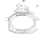
- FIG. 6 shows a band type radio device 50B according to the second embodiment, which also shows a state of being wound around the arm 100 as in FIG.
- the band-type radio device 50A of the first embodiment shown in FIG. 5 has the merit that the antenna characteristic does not deteriorate even when not worn on the arm as described above, but when the belt is worn on the arm 100, the first belt 4 Is folded back, and the metal part 5 provided on the first belt 4 is folded back, and as shown by the arrows in FIG. Degradation occurs.
- the metal part 5 is in the second state when the switch 15 is turned off when the arm 100 is worn. Since it is insulated from the ground part 3 b, no current flows through the metal part 5. Therefore, no antiphase antenna current is generated.
- the second ground portion 3b is coupled to the arm 100 and the arm 100 is regarded as a ground conductor. Antenna characteristics are ensured.
- the band-type radio device 50B of the second embodiment not only the stable antenna characteristic when not worn on the arm but also the reverse phase when worn on the arm 100 is realized. It is possible to suppress the generation of the antenna current and to secure stable antenna characteristics.
- both belts are connected to the main body 1 with the main body 1 interposed therebetween.
- both belts are disposed along the circumference of the arm 100 from one end of the main body 1 to the end facing the main body 1. Is different.
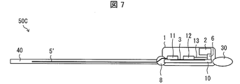
- FIG. 7 is a cross-sectional view showing the configuration of the band-type radio device 50C of the third embodiment, and shows a state when it is not worn on the arm.
- FIG. 8 shows a state where the band-type radio device 50C of the third embodiment is worn on the arm.
- a belt fixing portion 30 is provided at a position on the opposite side of the main belt 1 from the first belt connecting portion 8.
- a belt 40 (one band) connected to the first belt connecting portion 8 is detachably fixed to the belt fixing portion 30.
- the belt 40 is provided with a metal portion 5 ′ substantially the same as the metal portion 5 described in the first embodiment.
- the metal part 5 ′ of the third embodiment is different from the metal part 5 of the first embodiment in that the length extending along the belt 40 is longer than that of the metal part 5 of the first embodiment. That is, in the third embodiment, since one belt that is continuous along the periphery of the arm 100 is provided, it can be said that there is a margin in the arrangement length of the metal portion 5 ′. Therefore, compared with the case where two belts are provided and the metal part 5 is provided on one of them, a long metal part 5 ′ can be provided on the belt.
- the metal portion 5 ′ is conductively connected to the ground conductor 3 in the vicinity of the first belt connecting portion 8 in the ground conductor 3, similarly to the metal portion 5 of the first embodiment.
- the metal portion 5 ′ extends along the belt 40 and is provided to the vicinity of the belt fixing portion 30. In FIG. 8, the metal portion 5 ′ is arranged far beyond the position on the arm 100 opposite to the position where the main body 1 is disposed.
- the length of the metal portion 5 ′ is long, and thus compared to the configuration of the band-type radio device 50A including the metal portion 5 of the first embodiment. Even for antennas having a lower resonance frequency, it is possible to ensure a sufficiently long ground conductor length and improve the antenna characteristics when not mounted on the arm.
- Band type radios 50A, 50B, and 50C are: Band-type radios 50A, 50B, and 50C that include an antenna 2 and ground conductors 3 and 3 'of the antenna 2 and are fixed to a target by bands (first belt 4 and belt 40), Metal parts 5 and 5 'disposed on the band (first belt 4 and belt 40), and metal parts 5 and 5' connected to the ground conductors 3 and 3 '. It is characterized by.
- the ground conductor of the antenna is conductively connected to the metal portion disposed in the band, so that even if the band-type radio is not worn on the arm, Since the area of the ground conductor can be ensured, stable antenna characteristics can be obtained.
- the ground conductor is combined with the arm, and the arm is regarded as the ground conductor, so that the antenna characteristics are ensured.
- the band-type radio devices 50A, 50B, and 50C according to aspect 2 of the present invention are the same as in aspect 1 described above. It is preferable that the antenna 2 is connected to a position of the ground conductors 3 and 3 ′ that faces the side that is electrically connected to the metal portions 5 and 5 ′.
- the reverse phase current of the antenna current flowing through the ground conductor and the metal part is reduced, so that the antenna characteristics when the band-type radio is not worn on the arm can be further improved.
- the band-type radio device 50B according to aspect 3 of the present invention is the above aspect 1 or 2,
- the ground conductor 3 ′ has a first ground part 3 a and a second ground part 3 b connected to the first ground part 3 a via the switch 15.
- the metal part 5 is electrically connected to the first ground part 3a.
- the antenna 2 is connected to the second ground portion 3b at a position facing the side where the metal portion 5 is conductively connected in the ground conductor 3 '.
- the band-type radio device 50B includes a detection unit (sensor 16) that detects the proximity of a human body, When the detection unit (sensor 16) detects the proximity of the human body, the switch 15 is turned off and the first ground unit 3a and the second ground unit 3b are not connected, and the detection unit (sensor 16) is not connected to the human body. If no proximity is detected, it is preferable that the switch 15 is turned on and the first ground portion 3a and the second ground portion 3b are brought into conduction.
- a band-type radio according to aspect 4 of the present invention is the above aspect 1 to 3,
- the length by which the metal parts 5, 5 ′ and the ground conductors 3, 3 ′ are connected is preferably not less than 1/8 wavelength and not more than 3/8 wavelength of the resonance frequency of the antenna 2.
- the reverse phase current of the antenna current flowing through the ground conductor and the metal part is reduced, so that the antenna characteristics when the band-type radio is not worn on the arm can be further improved.
- the resonance condition of the antenna system composed of the antenna, the ground conductor, and the metal part becomes good, so that the antenna characteristics when the band-type radio is not worn on the arm are improved. Further improvements can be made.
- the band-type wireless device according to aspect 5 of the present invention is the above aspect 1 to 4, It is preferable to be fixed to the object by one band (belt 40).
- the aspect fixed to the said object with one band is compared with the structure which arrange
- the length of the band is inevitably increased, and the length of the metal portion disposed on the band can be increased. Therefore, a sufficiently long ground conductor can be secured even for an antenna having a lower resonance frequency. As a result, the antenna characteristics when the band-type wireless device is not worn on the arm can be improved.
- the “single band” referred to here is an aspect continuously arranged between the first belt connecting portion 8 and the belt fixing portion 30 of the main body 1 in the third embodiment. All included. That is, for example, the belt 40 in the third embodiment includes a plurality of layers in addition to a structure in which a plurality of pieces are connected between the first belt connecting portion 8 and the belt fixing portion 30. It is included even if it is made.
- the present invention can be suitably used as a wristwatch type antenna device.
Landscapes
- Engineering & Computer Science (AREA)
- Computer Networks & Wireless Communication (AREA)
- Signal Processing (AREA)
- Details Of Aerials (AREA)
- Support Of Aerials (AREA)
- Transceivers (AREA)
- Telephone Set Structure (AREA)
Abstract
本発明の一形態におけるバンド型無線機(50A)は、本体(1)にアンテナ(2)と地導体(3)とを内蔵し、当該地導体(3)が、本体(1)に連結された第一のベルト(4)に設けられた金属部(5)と導通接続している。
Description
本発明は、腕時計のように人の腕に装着することができるバンド型無線機に関する。
腕等に装着して使用するバンド型無線機に搭載されるアンテナ装置は、小型または携帯性を確保するために、バンド内部に実装されたり、筺体内部に内蔵されたりする。
特許文献1には、腕装着時において高いアンテナ利得と良好なアンテナ指向性を確保することを目的とした腕時計型無線機用アンテナ装置が記載されている。特許文献1の腕時計型無線機用アンテナ装置は、腕時計本体の内部に内蔵して設置されるヘリカルアンテナであって、前記腕時計を腕に装着して人体の正面に構えた状態においてヘリカルアンテナを人体から遠ざかる正面方向寄りに配置し、ヘリカルアンテナの軸方向が腕に対して略平行に配置された主プリント基板と垂直になるように配置し接続する手段を備えており、ヘリカルアンテナに対して腕を接地導体と見なし、腕に対してヘリカルアンテナの主偏波方向が垂直となるように動作させる。ヘリカルアンテナに対して腕を接地導体とみなし、腕に対してヘリカルアンテナの主偏波方向が垂直となるように動作させることにより、腕に装着したときの利得劣化を防いでいる。
しかしながら、上述のような特許文献1の構成は、ヘリカルアンテナに対して腕を接地導体とみなしているため、腕に装着していない場合には接地導体が無くなりアンテナ特性が劣化するという問題がある。
そこで、本発明は上記の問題点に鑑みてなされたものであり、その目的は、腕に装着していない場合でも安定したアンテナ特性を得ることができるバンド型無線機を提供することにある。
上記の課題を解決するために、本発明の一態様に係るバンド型無線機は、
アンテナおよび当該アンテナの地導体を備え、バンドにより対象に固定されるバンド型無線機であって、
上記バンドに配設された金属部であって、上記地導体と導通接続される金属部を備えていることを特徴としている。
アンテナおよび当該アンテナの地導体を備え、バンドにより対象に固定されるバンド型無線機であって、
上記バンドに配設された金属部であって、上記地導体と導通接続される金属部を備えていることを特徴としている。
本発明の一態様によれば、アンテナの地導体が、バンドに配設される金属部と導通接続されることにより、バンド型無線機を腕に装着していない場合であっても、当該金属部によって地導体の面積を確保することができるため、安定したアンテナ特性を得ることができる。
〔実施形態1〕
以下、本発明に係るバンド型無線機の一実施形態について、図1および図2を用いて説明する。
以下、本発明に係るバンド型無線機の一実施形態について、図1および図2を用いて説明する。
本発明に係るバンド型無線機は、取り付け対象物である腕あるいは脚に当該無線機に配設されたバンドを巻きつけて取り付けるタイプの無線機である。本実施形態1では、取り付け対象物を腕とした腕時計型の無線機を例に挙げて、本発明の一実施形態を説明する。
図1は、本実施形態1のバンド型無線機の構成を示す断面図である。また、図2は、本実施形態1のバンド型無線機の構成を示す上面図である。なお、図1には、取り付け対象物である腕100を示すとともに、仮想線でバンド型無線機50Aが腕100に巻き付けられた状態も併せて示す。
本実施形態1のバンド型無線機50Aは、人体の腕等に装着して用いられ、無線通信により外部からの情報を受信可能な電子機器であり、特に、人体の腕等に継続して装着する携帯型の電子機器である。このようなバンド型無線機50Aの例として、腕時計、歩数計、血圧計、心拍計、・・・等が挙げられる。
本実施形態1のバンド型無線機50Aは、本体1と、本体1に内蔵されるアンテナ2と、本体1に内蔵されるアンテナ2の地導体3と、本体1に接続される第一のベルト4(バンド)と、第一のベルト4に設けられた金属部5とを有し、金属部5は地導体3と導通接続されている。更に、本体1には、基板10、締結コネクタ11、無線回路部12、および給電線路13が内蔵されている。
第一のベルト4は、本体1に第一のベルト連結部8を介して固定されている。また、本体1には、第一のベルト連結部8に対向する位置に第二のベルト連結部9が配設されており、第二のベルト連結部9を介して第二のベルト7が本体1に接続されている。
なお、第一のベルト連結部8および第二のベルト連結部9はいずれも、本体1の一部から構成されていてもよいし、本体1とは別体として構成されていてもよい。
第一のベルト4および第二のベルト7は、図1中に仮想線で示すように腕100の周囲に沿って配することができる。これは、第一のベルト連結部8および第二のベルト連結部9がそれぞれ第一のベルト4および第二のベルト7を、本体1に対して回動可能に連結しているためであり、且つ、第一のベルト4および第二のベルト7が腕100の周囲に沿うように変形することができるためである。ここで変形とは、ゴム素材のように変形する態様に限らず、後述するように複数の駒を有したベルトであって駒同士がピンなどで連結しておりピンを中心に駒が回動することによってベルトの形状を変えることができる態様も含まれる。
第一のベルト4および第二のベルト7における、ベルト連結部に連結している端部とは反対側の端部は、腕100の周囲に沿うように第一のベルト4および第二のベルト7を配置したときに、留め具構造(不図示)によって互いは留められる。このとき、仮想線で図示したように、第二のベルト7の端部およびその近傍領域における第二のベルト7の外側面と、第一のベルト4の端部およびその近傍領域における第一のベルト4の内側面(腕側の面)とが重なり合うように、第一のベルト4および第二のベルト7の長さは設計されている。なお、上記留め具構造としては特に限定されず、穴留め式のピンバックル構造であってもよいし、片開き式、両開き式又は二重ロック式のバックル構造であってもよい。ここで、片開き式のバックル構造とは、バックル部分の片側のみが開く構造であり、両開き式のバックル構造とは、バックル接合部が両側に開く構造である。また、二重ロック式のバックル構造とは、片開き式のバックルの開く部分に留め金が付いた構造である。
本体1は、アンテナ2、地導体3、アンテナ給電部6、締結コネクタ11、無線回路部12、および給電線路13を、基板10上に搭載している。本体1には、更に、時計の文字盤、ディスプレイ、入力装置等のユーザインターフェース等を搭載することができる。
地導体3は、基板10上に形成されたGNDパターンである。地導体3は、本体1における腕100に近接している側に設けられており、腕100とアンテナ2との間に位置している。また、地導体3上の第一のベルト4に近接した辺に沿って締結コネクタ11が配設されている。また、地導体3上の締結コネクタ11と、アンテナ2との間に、無線回路部12が配設されている。
ここで、本実施形態1のバンド型無線機50Aは、携帯電話などよりも更に小型の端末とすることができる。しかしながら、そのような小型の端末では、本体1内の地導体3だけでは長さが足りず、共振するために十分な鏡像電流が得られないため、十分なアンテナ性能が得られない。そこで、本実施形態では、金属部5を設けて地導体3を延長することで、共振するために十分な鏡像電流が生じて、十分なアンテナ性能を確保することができる。また、腕に巻いているときには地導体3と腕が結合して、腕も仮想的な地導体と見なすことによって、アンテナ性能を確保することができる。
アンテナ2は、金属部5が導通接続されている辺と対向する位置において地導体3と接続(アンテナ給電部6)されている。アンテナ2は、アンテナ給電部6を介して基板10上の給電線路13に接続され、給電線路13は無線回路部12に接続される。アンテナが送受信する信号も、この経路で処理される。
アンテナ2は、本体1における腕100から離れた側に設けられている。アンテナ2は、従来公知の薄板状、線状等のアンテナを使用することができる。
地導体3の第一のベルト連結部8近傍において締結コネクタ11を介して地導体3と導通接続されている金属部5は、第一のベルト連結部8を経由して第一のベルト4に延設されている。
金属部5は、第一のベルト4の第一のベルト連結部8側の端部から反対側の端部に向かって延設されており、図1に長さLで示した地導体3と金属部5との合計の長さは、アンテナ2の共振周波数の1/8波長以上3/8波長以下となるように、好ましくは1/4波長となるように設計されている。
ここで、本実施形態1では、第一のベルト4がゴムバンドであることを想定している。この場合、金属部5は金属箔などで形成され、ゴムバンドの内部、または表面にゴムバンドと一体成型される。金属箔としては、主にフレキシブル基板上のパターン(銅)が挙げられるが、アルミ、ステンレス、銅などの箔でもよい。厚さはフレキシブル基板上パターンで有れば40μm程度とすることができるが、この数値に限定されるものではない。
なお、先述したように金属部5と基板10との接続手段は、基板10上にフレキシブル基板用の締結コネクタ11を実装して、フレキシブル基板で形成された金属部5を、この締結コネクタ11を介して基板10と接続する。しかしながら、この態様に限定されるものではなく、フレキシブル基板やアルミ箔、銅箔、ステンレス箔(金属部5)を、本体1内の地導体3に半田付けしても良い。
ここで、第一のベルト4は、先述したように複数の駒を有したベルトであって駒同士がピンなどで連結してなるものであってもよい。そこで、駒を連結した態様について、図3に基づいて説明する。図3は、図2の変形例を示す上面図である。複数の駒44がピン15によって連結されて、第一のベルト4を構成している。この態様において、金属部5は、本体1に最も近い駒44とこれに連なる幾つかの駒44を金属によって形成し、且つ、これら金属の駒44同士を、駒同士を導通接続する金属のピン15によって連結した構成によって実現することができる。この態様において、本体1に最も近い駒44は、ビス14によって地導体3にビス留めされて導通接続される。また、この態様において、先述の長さ(L)を越える長さに位置する駒45は、非金属製のものを用いることができる。あるいは、駒自体は金属であるが、それを連結するピンを非導通のピンとしてもよい。
なお、第二のベルト7には金属部5は設けられていない。
このように地導体3に導通接続した金属部5が第一のベルト4に設けられていることによって、バンド型無線機50Aを腕に装着していないときであっても、金属部5により地導体の面積を確保することができる。そのため、バンド型無線機50Aを腕に装着していないときであっても、安定したアンテナ特性を得ることができる。
また、アンテナ2は、地導体3から、金属部5が導通接続されている辺と対向する位置で給電されている。そのため、地導体3および金属部5に流れるアンテナ電流の逆相電流が軽減するため、非装着時のアンテナ特性が更に改善する。
また、金属部5と地導体3とが接続された長さ(L)が、アンテナ2の共振周波数における略4分の1波長となっているため、地導体3および金属部5に流れるアンテナ電流の逆相電流が軽減し、非装着時のアンテナ特性が更に改善する。また、長さ(L)が上述のように設計されているため、アンテナ2、地導体3および金属部5で構成されるアンテナ系の共振条件が良好になり、非装着時のアンテナ特性が更に改善する。
なお、本実施形態1では、本体1を挟んで両側にそれぞれ別体のベルトを配した構成を説明したが、本発明はこれに限定されるものではなく、一本のベルトを本体1の一方の端部から他方の端部までループ状に配して、この一本のベルトが腕100に巻き付くように構成してもよい。このとき、図1に示した長さLを実現する金属部5をベルトにおける本体1の一方の端部から配設すればよい。また例えば、本体1の他方の端部にこの一本のベルトの一端を着脱可能に固定することができる固定部材が配設すればよい。
なお、第二のベルト7に、地導体とは絶縁された金属部を配設してもよい。
〔実施形態2〕
本発明に係るバンド型無線機の他の実施形態について、図4から図6に基づいて説明すれば、以下のとおりである。なお、説明の便宜上、上記実施形態1にて説明した部材と同じ機能を有する部材については、同じ符号を付記し、その説明を省略する。
本発明に係るバンド型無線機の他の実施形態について、図4から図6に基づいて説明すれば、以下のとおりである。なお、説明の便宜上、上記実施形態1にて説明した部材と同じ機能を有する部材については、同じ符号を付記し、その説明を省略する。
上述の実施形態1におけるバンド型無線機50Aとの相違点を、図4に基づいて説明する。図4は、本実施形態2におけるバンド型無線機50Bの構成を示す断面図である。図4は、実施形態1の図1に対応している。
本実施形態2のバンド型無線機50Bは、地導体3´が、第一のグランド部3aと、当該第一のグランド部3aとスイッチ15を介して接続された第二のグランド部3bとを有している。また、金属部5は、この第一のグランド部3aと導通接続されている。
そして、アンテナ2は、地導体3´における、金属部5が導通接続されている辺と対向する位置において、第二のグランド部3bと接続(アンテナ給電部6)されている。
また、本実施形態2のバンド型無線機50Bは、人体の近接を検知するセンサ16(検知部)を本体1の底面に備えている。そして、センサ16が人体の近接を検知するとスイッチ15がオフとなって第一のグランド部3aと第二のグランド部3bとは導通せず、センサ16が人体の近接を検知しないとスイッチ15がオンとなって第一のグランド部3aと第二のグランド部3bとが導通する構成となっている。
本実施形態2においても実施形態1と同様に、地導体3´と金属部5との合計の長さ(L)、すなわち、第二のグランド部3bにおける金属部5から最も離れた位置にある端部から、金属部5における地導体3´から最も離れた位置にある端部までの長さは、アンテナ2の共振周波数の略4分の1波長となるように設計されている。
本実施形態2の構成のメリットは、実施形態1のバンド型無線機50Aよりもアンテナ特性が安定している点にある。これについて、図5および図6を用いて説明する。
図5は、実施形態1のバンド型無線機50Aを示しており、腕100に巻き付けた状態を示している。図6は、本実施形態2のバンド型無線機50Bを示しており、こちらも図5と同様、腕100に巻き付けた状態を示している。
図5に示す実施形態1のバンド型無線機50Aは、先述したように腕に装着していない場合でもアンテナ特性が劣化しないというメリットがあるものの、腕100に装着したときに第一のベルト4が折り返されることによって第一のベルト4に設けられた金属部5が折り返されて、図5中に矢印で示すように金属部5上に逆相のアンテナ電流が生じ、打ち消し合うことでアンテナ特性の劣化が生じる。
これに対して、センサ16を具備した本実施形態2のバンド型無線機50Bの構成によれば、腕100に装着しているときには、スイッチ15がオフになることで金属部5は第二のグランド部3bから絶縁されるため、金属部5に電流は流れない。そのため、逆相のアンテナ電流は発生しない。
更に、本実施形態2のバンド型無線機50Bの構成によれば、腕100に装着しているときは、第二のグランド部3bが腕100と結合して腕100が地導体とみなされるため、アンテナ特性は確保される。
このように、本実施形態2のバンド型無線機50Bの構成によれば、腕に装着していないときの安定したアンテナ特性の実現は勿論のこと、腕100に装着しているときの逆相のアンテナ電流の発生を抑制するとともに安定したアンテナ特性を確保することができるという効果を奏する。
〔実施形態3〕
本発明に係るバンド型無線機の他の実施形態について、図7および図8に基づいて説明すれば、以下のとおりである。なお、説明の便宜上、上記実施形態1にて説明した部材と同じ機能を有する部材については、同じ符号を付記し、その説明を省略する。
本発明に係るバンド型無線機の他の実施形態について、図7および図8に基づいて説明すれば、以下のとおりである。なお、説明の便宜上、上記実施形態1にて説明した部材と同じ機能を有する部材については、同じ符号を付記し、その説明を省略する。
上記実施形態1では、本体1を挟んで、それぞれ別体のベルト(バンド)を本体1に連結させている。これに対して本実施形態3では、本体1の一方の端部からこれに対向する端部に至るまで、腕100の周囲に沿って連続する一本のベルトを配設している点において両者は相違している。
図7は、本実施形態3のバンド型無線機50Cの構成を示す断面図であり、腕に装着していないときの状態を示す。一方、図8は、本実施形態3のバンド型無線機50Cを腕に装着した状態を示す。
本実施形態3のバンド型無線機50Cは、本体1における第一のベルト連結部8とは反対側の位置に、ベルト固定部30が設けられている。第一のベルト連結部8に連結したベルト40(一本のバンド)は、このベルト固定部30に着脱可能に固定されている。
ベルト40には、実施形態1において説明した金属部5と略同じ金属部5´が設けられている。本実施形態3の金属部5´は、実施形態1の金属部5に比べて、ベルト40に沿って延設される長さが長い点で両者は相違している。すなわち、本実施形態3は腕100の周囲に沿って連続する一本のベルトを配設しているため、金属部5´の配設長に余裕があると言える。そのため、二本のベルトを配設してその一本に金属部5を設ける場合と比較して、長い金属部5´をベルトに設けることができる。
金属部5´は、実施形態1の金属部5と同様に、地導体3における第一のベルト連結部8近傍において、地導体3と導通接続している。そして、金属部5´は、ベルト40に沿って延設され、ベルト固定部30の近傍まで設けられている。図8では、金属部5´は、腕100における本体1の配設位置とは反対側の位置を大きく超えて配されている。
このように本実施形態3のバンド型無線機50Cの構成によれば、金属部5´の長さが長いため、実施形態1の金属部5を具備したバンド型無線機50Aの構成に比べて、より低い共振周波数のアンテナに対しても、十分な長さの地導体長さを確保することができて、腕に装着していないときのアンテナ特性を改善することができるという効果を奏する。
〔まとめ〕
本発明の態様1に係るバンド型無線機50A、50B、50Cは、
アンテナ2および当該アンテナ2の地導体3、3´を備え、バンド(第一のベルト4、ベルト40)により対象に固定されるバンド型無線機50A、50B、50Cであって、
上記バンド(第一のベルト4、ベルト40)に配設された金属部5、5´であって、上記地導体3、3´と導通接続される金属部5、5´を備えていることを特徴としている。
本発明の態様1に係るバンド型無線機50A、50B、50Cは、
アンテナ2および当該アンテナ2の地導体3、3´を備え、バンド(第一のベルト4、ベルト40)により対象に固定されるバンド型無線機50A、50B、50Cであって、
上記バンド(第一のベルト4、ベルト40)に配設された金属部5、5´であって、上記地導体3、3´と導通接続される金属部5、5´を備えていることを特徴としている。
上記の構成によれば、アンテナの地導体が、バンドに配設される金属部と導通接続されることにより、バンド型無線機を腕に装着していない場合であっても、当該金属部によって地導体の面積を確保することができるため、安定したアンテナ特性を得ることができる。
なお、バンド型無線機を腕に装着しているときには、上記地導体が腕と結合して、腕が地導体とみなされるため、アンテナ特性は確保される。
本発明の態様2に係るバンド型無線機50A、50B、50Cは、上記態様1において、
上記アンテナ2は、上記地導体3、3´における、上記金属部5、5´と導通接続される辺と対向する位置に接続されていることが好ましい。
上記アンテナ2は、上記地導体3、3´における、上記金属部5、5´と導通接続される辺と対向する位置に接続されていることが好ましい。
上記の構成によれば、地導体、金属部に流れるアンテナ電流の逆相電流が軽減するため、バンド型無線機を腕に装着していないときのアンテナ特性をより一層改善させることができる。
本発明の態様3に係るバンド型無線機50Bは、上記態様1または2において、
上記地導体3´は、第一のグランド部3aと、当該第一のグランド部3aとスイッチ15を介して接続された第二のグランド部3bとを有し、
上記金属部5は、上記第一のグランド部3aと導通接続され、
上記アンテナ2は、上記地導体3´における、上記金属部5が導通接続されている辺と対向する位置において、上記第二のグランド部3bと接続されており、
上記バンド型無線機50Bは、人体の近接を検知する検知部(センサ16)を備えており、
上記検知部(センサ16)が人体の近接を検知すると上記スイッチ15がオフとなって第一のグランド部3aと第二のグランド部3bとは導通せず、上記検知部(センサ16)が人体の近接を検知しないと上記スイッチ15がオンとなって第一のグランド部3aと第二のグランド部3bとが導通することが好ましい。
上記地導体3´は、第一のグランド部3aと、当該第一のグランド部3aとスイッチ15を介して接続された第二のグランド部3bとを有し、
上記金属部5は、上記第一のグランド部3aと導通接続され、
上記アンテナ2は、上記地導体3´における、上記金属部5が導通接続されている辺と対向する位置において、上記第二のグランド部3bと接続されており、
上記バンド型無線機50Bは、人体の近接を検知する検知部(センサ16)を備えており、
上記検知部(センサ16)が人体の近接を検知すると上記スイッチ15がオフとなって第一のグランド部3aと第二のグランド部3bとは導通せず、上記検知部(センサ16)が人体の近接を検知しないと上記スイッチ15がオンとなって第一のグランド部3aと第二のグランド部3bとが導通することが好ましい。
バンド型無線機を腕に装着している際、すなわちベルトを腕に巻いた際、ベルトが折れ曲がって当該ベルトに配設された金属部上に逆相のアンテナ電流が生じてアンテナ特性が劣化する虞がある。しかしながら、上記態様3の構成によれば、バンド型無線機を腕に装着しているときには、金属部が第二のグランド部から絶縁されるためアンテナ電流は流れず、逆相のアンテナ電流は発生しない。また、バンド型無線機を腕に装着しているときには、第二のグランド部が腕と結合して、腕が地導体とみなされるため、アンテナ特性は確保される。
本発明の態様4に係るバンド型無線機は、上記態様1から3において、
上記金属部5、5´と上記地導体3、3´とが接続された長さが、上記アンテナ2の共振周波数の1/8波長以上3/8波長以下となっていることが好ましい。
上記金属部5、5´と上記地導体3、3´とが接続された長さが、上記アンテナ2の共振周波数の1/8波長以上3/8波長以下となっていることが好ましい。
上記の構成によれば、地導体、金属部に流れるアンテナ電流の逆相電流が軽減するため、バンド型無線機を腕に装着していないときのアンテナ特性をより一層改善させることができる。
また、上記の構成によれば、アンテナと、地導体と、金属部とにより構成されるアンテナ系の共振条件が良好となるため、バンド型無線機を腕に装着していないときのアンテナ特性を更に改善させることができる。
本発明の態様5に係るバンド型無線機は、上記態様1から4において、
一本の上記バンド(ベルト40)により上記対象に固定されることが好ましい。
一本の上記バンド(ベルト40)により上記対象に固定されることが好ましい。
上記の構成によれば、一本のバンド(ベルト40)により上記対象に固定される態様のほうが、二本のバンド(第一のベルト4および第二のベルト7)を配設する構成に比べて、バンドの長さが必然的に長くなり、当該バンドに配設される金属部の長さを長くすることが可能である。そのため、より低い共振周波数のアンテナに対しても十分な長さの地導体を確保することができる。これにより、バンド型無線機を腕に装着していないときのアンテナ特性を良好なものとすることができる。
なお、ここでいう「一本のバンド」とは、実施形態3でいうところの本体1の第一のベルト連結部8とベルト固定部30との間に連続して配される態様であれば全て含まれる。すなわち、例えば、第一のベルト連結部8とベルト固定部30との間に複数の駒を連ねて構成されるものも含まれるほか、実施形態3でいうところのベルト40が複数の層を積層してなるものであっても含まれる。
本発明は上述した各実施形態に限定されるものではなく、請求項に示した範囲で種々の変更が可能であり、異なる実施形態にそれぞれ開示された技術的手段を適宜組み合わせて得られる実施形態についても本発明の技術的範囲に含まれる。さらに、各実施形態にそれぞれ開示された技術的手段を組み合わせることにより、新しい技術的特徴を形成することができる。
本発明は、腕時計型のアンテナ装置として好適に利用することができる。
1 本体
2 アンテナ
3、3´ 地導体
3a 第一のグランド部
3b 第二のグランド部
4 第一のベルト(バンド)
5、5´ 金属部
6 アンテナ給電部
7 第二のベルト
8 第一のベルト連結部
9 第二のベルト連結部
10 基板
11 締結コネクタ
12 無線回路部
13 給電線路
14 ビス
15 スイッチ
16 センサ(検知部)
30 ベルト固定部
40 ベルト(バンド、一本のバンド)
44、45 駒
50A、50B、50C バンド型無線機
100 腕
2 アンテナ
3、3´ 地導体
3a 第一のグランド部
3b 第二のグランド部
4 第一のベルト(バンド)
5、5´ 金属部
6 アンテナ給電部
7 第二のベルト
8 第一のベルト連結部
9 第二のベルト連結部
10 基板
11 締結コネクタ
12 無線回路部
13 給電線路
14 ビス
15 スイッチ
16 センサ(検知部)
30 ベルト固定部
40 ベルト(バンド、一本のバンド)
44、45 駒
50A、50B、50C バンド型無線機
100 腕
Claims (5)
- アンテナおよび当該アンテナの地導体を備え、バンドにより対象に固定されるバンド型無線機であって、
上記バンドに配設された金属部であって、上記地導体と導通接続される金属部を備えていることを特徴とするバンド型無線機。 - 上記アンテナは、上記地導体における、上記金属部と導通接続される辺と対向する位置に接続されていることを特徴とする請求項1に記載のバンド型無線機。
- 上記地導体は、第一のグランド部と、当該第一のグランド部とスイッチを介して接続された第二のグランド部とを有し、
上記金属部は、上記第一のグランド部と導通接続され、
上記アンテナは、上記地導体における、上記金属部が導通接続されている辺と対向する位置において、上記第二のグランド部と接続されており、
上記バンド型無線機は、人体の近接を検知する検知部を備えており、
上記検知部が人体の近接を検知すると上記スイッチがオフとなって第一のグランド部と第二のグランド部とは導通せず、上記検知部が人体の近接を検知しないと上記スイッチがオンとなって第一のグランド部と第二のグランド部とが導通することを特徴とする請求項1または2に記載のバンド型無線機。 - 上記金属部と上記地導体とが接続された長さが、上記アンテナの共振周波数の1/8波長以上3/8波長以下となっていることを特徴とする請求項1から3までの何れか1項に記載のバンド型無線機。
- 一本の上記バンドにより上記対象に固定されることを特徴とする請求項1から4までの何れか1項に記載のバンド型無線機。
Priority Applications (1)
| Application Number | Priority Date | Filing Date | Title |
|---|---|---|---|
| US14/771,224 US9503144B2 (en) | 2013-09-18 | 2014-07-15 | Band-type wireless communication device |
Applications Claiming Priority (2)
| Application Number | Priority Date | Filing Date | Title |
|---|---|---|---|
| JP2013-193249 | 2013-09-18 | ||
| JP2013193249A JP6309728B2 (ja) | 2013-09-18 | 2013-09-18 | バンド型無線機 |
Publications (1)
| Publication Number | Publication Date |
|---|---|
| WO2015040940A1 true WO2015040940A1 (ja) | 2015-03-26 |
Family
ID=52688600
Family Applications (1)
| Application Number | Title | Priority Date | Filing Date |
|---|---|---|---|
| PCT/JP2014/068767 Ceased WO2015040940A1 (ja) | 2013-09-18 | 2014-07-15 | バンド型無線機 |
Country Status (3)
| Country | Link |
|---|---|
| US (1) | US9503144B2 (ja) |
| JP (1) | JP6309728B2 (ja) |
| WO (1) | WO2015040940A1 (ja) |
Families Citing this family (3)
| Publication number | Priority date | Publication date | Assignee | Title |
|---|---|---|---|---|
| US9653786B2 (en) * | 2015-06-27 | 2017-05-16 | Intel Corporation | Wearable antenna system |
| KR101913847B1 (ko) * | 2016-10-07 | 2018-11-01 | 단국대학교 천안캠퍼스 산학협력단 | 이어폰 감개 겸용 팔찌 |
| EP4092493A1 (fr) * | 2021-05-21 | 2022-11-23 | ETA SA Manufacture Horlogère Suisse | Montre comportant un dispositif de communication en champs proche |
Citations (3)
| Publication number | Priority date | Publication date | Assignee | Title |
|---|---|---|---|---|
| JPH10271060A (ja) * | 1997-03-24 | 1998-10-09 | Brother Ind Ltd | 携帯用無線通信装置 |
| JP2001116858A (ja) * | 1999-10-19 | 2001-04-27 | Citizen Watch Co Ltd | 腕時計 |
| JP2004312707A (ja) * | 2003-03-24 | 2004-11-04 | Seiko Instruments Inc | 腕装着型通信装置及びこれを備えた情報端末装置 |
Family Cites Families (6)
| Publication number | Priority date | Publication date | Assignee | Title |
|---|---|---|---|---|
| JP3560455B2 (ja) | 1997-12-10 | 2004-09-02 | パナソニック モバイルコミュニケーションズ株式会社 | 腕時計型無線機用アンテナ装置 |
| JP3523043B2 (ja) * | 1998-01-20 | 2004-04-26 | 株式会社エヌ・ティ・ティ・ドコモ | 腕時計型通信機およびそのアンテナ |
| JP2003152582A (ja) * | 2001-11-13 | 2003-05-23 | Seiko Epson Corp | 腕装着型の無線機能付き電子機器 |
| EP2201693A1 (en) * | 2007-10-09 | 2010-06-30 | QUALCOMM Incorporated | Apparatus including housing incorporating a radiating element of an antenna |
| US9098991B2 (en) * | 2013-01-15 | 2015-08-04 | Fitbit, Inc. | Portable monitoring devices and methods of operating the same |
| CN104749948B (zh) * | 2013-12-30 | 2017-09-22 | 深圳富泰宏精密工业有限公司 | 穿戴式电子装置 |
-
2013
- 2013-09-18 JP JP2013193249A patent/JP6309728B2/ja not_active Expired - Fee Related
-
2014
- 2014-07-15 WO PCT/JP2014/068767 patent/WO2015040940A1/ja not_active Ceased
- 2014-07-15 US US14/771,224 patent/US9503144B2/en not_active Expired - Fee Related
Patent Citations (3)
| Publication number | Priority date | Publication date | Assignee | Title |
|---|---|---|---|---|
| JPH10271060A (ja) * | 1997-03-24 | 1998-10-09 | Brother Ind Ltd | 携帯用無線通信装置 |
| JP2001116858A (ja) * | 1999-10-19 | 2001-04-27 | Citizen Watch Co Ltd | 腕時計 |
| JP2004312707A (ja) * | 2003-03-24 | 2004-11-04 | Seiko Instruments Inc | 腕装着型通信装置及びこれを備えた情報端末装置 |
Also Published As
| Publication number | Publication date |
|---|---|
| JP6309728B2 (ja) | 2018-04-11 |
| JP2015061188A (ja) | 2015-03-30 |
| US9503144B2 (en) | 2016-11-22 |
| US20160006472A1 (en) | 2016-01-07 |
Similar Documents
| Publication | Publication Date | Title |
|---|---|---|
| CN102738556B (zh) | 用于便携式终端的天线设备及具有天线设备的便携式终端 | |
| EP3665743B1 (en) | Antenna for a wearable audio device | |
| JP6005321B2 (ja) | 多目的アンテナ | |
| KR102737266B1 (ko) | 안테나를 포함하는 웨어러블 전자 장치 | |
| CN104518273B (zh) | 穿戴式电子装置 | |
| US20180070179A1 (en) | Wireless Headset Antennas | |
| JP5956088B2 (ja) | マルチモードアンテナを有する端末 | |
| TW201721962A (zh) | 天線模組及具有該天線模組之穿戴式電子裝置 | |
| JP2015046879A (ja) | 無線通信装置 | |
| WO2012160820A1 (ja) | 携帯無線装置 | |
| JP6309728B2 (ja) | バンド型無線機 | |
| JP2006191437A (ja) | 携帯無線機 | |
| WO2011016160A1 (ja) | 携帯無線機 | |
| TW201501411A (zh) | 無線通訊裝置 | |
| TW201517373A (zh) | 穿戴式通訊裝置 | |
| TWI552441B (zh) | 在腕戴式無線設備中用於製作多頻帶天線的方法以及用於多頻帶天線的設備 | |
| TWI573317B (zh) | 無線通訊裝置 | |
| JP2014517605A (ja) | 接地面伸長部を組み込んだ首紐 | |
| JP5125616B2 (ja) | アンテナ | |
| WO2015029610A1 (ja) | バンド型無線機 | |
| JP2006222528A (ja) | 携帯無線装置及びアンテナ装置 | |
| KR101888719B1 (ko) | Sar 저감수단을 구비한 웨어러블 기기 | |
| JP2020005198A (ja) | 無線通信装置 | |
| JP2012227743A (ja) | 携帯無線機 | |
| TWI523313B (zh) | 電子裝置 |
Legal Events
| Date | Code | Title | Description |
|---|---|---|---|
| 121 | Ep: the epo has been informed by wipo that ep was designated in this application |
Ref document number: 14845492 Country of ref document: EP Kind code of ref document: A1 |
|
| WWE | Wipo information: entry into national phase |
Ref document number: 14771224 Country of ref document: US |
|
| NENP | Non-entry into the national phase |
Ref country code: DE |
|
| 122 | Ep: pct application non-entry in european phase |
Ref document number: 14845492 Country of ref document: EP Kind code of ref document: A1 |