WO2015037342A1 - Communication apparatus and communication method - Google Patents
Communication apparatus and communication method Download PDFInfo
- Publication number
- WO2015037342A1 WO2015037342A1 PCT/JP2014/069620 JP2014069620W WO2015037342A1 WO 2015037342 A1 WO2015037342 A1 WO 2015037342A1 JP 2014069620 W JP2014069620 W JP 2014069620W WO 2015037342 A1 WO2015037342 A1 WO 2015037342A1
- Authority
- WO
- WIPO (PCT)
- Prior art keywords
- unit
- symbol
- symbol point
- modulation
- communication
- Prior art date
Links
Images


Classifications
-
- H—ELECTRICITY
- H04—ELECTRIC COMMUNICATION TECHNIQUE
- H04L—TRANSMISSION OF DIGITAL INFORMATION, e.g. TELEGRAPHIC COMMUNICATION
- H04L27/00—Modulated-carrier systems
- H04L27/0008—Modulated-carrier systems arrangements for allowing a transmitter or receiver to use more than one type of modulation
-
- H—ELECTRICITY
- H04—ELECTRIC COMMUNICATION TECHNIQUE
- H04L—TRANSMISSION OF DIGITAL INFORMATION, e.g. TELEGRAPHIC COMMUNICATION
- H04L1/00—Arrangements for detecting or preventing errors in the information received
- H04L1/0001—Systems modifying transmission characteristics according to link quality, e.g. power backoff
- H04L1/0002—Systems modifying transmission characteristics according to link quality, e.g. power backoff by adapting the transmission rate
- H04L1/0003—Systems modifying transmission characteristics according to link quality, e.g. power backoff by adapting the transmission rate by switching between different modulation schemes
-
- H—ELECTRICITY
- H04—ELECTRIC COMMUNICATION TECHNIQUE
- H04L—TRANSMISSION OF DIGITAL INFORMATION, e.g. TELEGRAPHIC COMMUNICATION
- H04L27/00—Modulated-carrier systems
- H04L27/32—Carrier systems characterised by combinations of two or more of the types covered by groups H04L27/02, H04L27/10, H04L27/18 or H04L27/26
- H04L27/34—Amplitude- and phase-modulated carrier systems, e.g. quadrature-amplitude modulated carrier systems
- H04L27/3405—Modifications of the signal space to increase the efficiency of transmission, e.g. reduction of the bit error rate, bandwidth, or average power
-
- H—ELECTRICITY
- H04—ELECTRIC COMMUNICATION TECHNIQUE
- H04L—TRANSMISSION OF DIGITAL INFORMATION, e.g. TELEGRAPHIC COMMUNICATION
- H04L27/00—Modulated-carrier systems
- H04L27/32—Carrier systems characterised by combinations of two or more of the types covered by groups H04L27/02, H04L27/10, H04L27/18 or H04L27/26
- H04L27/34—Amplitude- and phase-modulated carrier systems, e.g. quadrature-amplitude modulated carrier systems
- H04L27/3488—Multiresolution systems
-
- H—ELECTRICITY
- H04—ELECTRIC COMMUNICATION TECHNIQUE
- H04L—TRANSMISSION OF DIGITAL INFORMATION, e.g. TELEGRAPHIC COMMUNICATION
- H04L1/00—Arrangements for detecting or preventing errors in the information received
- H04L1/004—Arrangements for detecting or preventing errors in the information received by using forward error control
- H04L1/0056—Systems characterized by the type of code used
- H04L1/0057—Block codes
-
- H—ELECTRICITY
- H04—ELECTRIC COMMUNICATION TECHNIQUE
- H04L—TRANSMISSION OF DIGITAL INFORMATION, e.g. TELEGRAPHIC COMMUNICATION
- H04L5/00—Arrangements affording multiple use of the transmission path
- H04L5/003—Arrangements for allocating sub-channels of the transmission path
- H04L5/0048—Allocation of pilot signals, i.e. of signals known to the receiver
-
- H—ELECTRICITY
- H04—ELECTRIC COMMUNICATION TECHNIQUE
- H04W—WIRELESS COMMUNICATION NETWORKS
- H04W4/00—Services specially adapted for wireless communication networks; Facilities therefor
- H04W4/80—Services using short range communication, e.g. near-field communication [NFC], radio-frequency identification [RFID] or low energy communication
Definitions
- the present disclosure relates to a communication device and a communication method.
- TransferJet (registered trademark) is adopted as a proximity wireless communication method in a digital camera, a PC (Personal Computer), and the like, and builds an ecosystem for data communication between information processing apparatuses.
- the TransferJet specifications are standardized by the TransferJet Consortium shown in Non-Patent Document 1 below, and PHY / CNL Specification 1.0 is used in the current product.
- Non-Patent Document 2 a standard almost similar to the standard by the TransferJet consortium is registered as ECMA 398 shown in Non-Patent Document 2 below.
- the present disclosure proposes a new and improved communication apparatus and communication method capable of realizing higher speed communication.
- a modulation unit that uses a symbol point having the same average power among a plurality of predetermined modulation schemes in each modulation scheme, and modulates transmission data by any one of the plurality of predetermined modulation schemes.
- a communication device is provided.
- symbol points having the same average power among a plurality of predetermined modulation schemes are used in each modulation scheme, and transmission data is modulated by any one of the predetermined plurality of modulation schemes.
- a communication method is provided.
- FIG. 2 is a block diagram illustrating a configuration of a communication device according to an embodiment of the present disclosure.
- FIG. It is a block diagram which shows the structure of the communication apparatus which concerns on a comparative example. It is a figure which shows the concept of Pi / 2 shift BPSK in a conventional system. It is a figure which shows 16QAM symbol point arrangement
- a communication apparatus performs communication processing improved from the communication processing defined in TransferJet Consortium (Non-Patent Document 1) and ECMA-398 (Non-Patent Document 2).
- the communication process defined in the TransferJet Consortium (Non-Patent Document 1) and ECMA-398 (Non-Patent Document 2) is also referred to as a conventional method, and the communication process improved in the present embodiment is also referred to as a proposed method.
- the transmission signal is multi-valued to realize high-speed transmission.
- the communication device uses 16QAM (Quadrature Amplitude Modulation) and QPSK (QuadratureKeeringPulse) in addition to Pi2 shift BPSK (Binary Phase Shift Keying) that has been adopted in the conventional method. adopt.
- the modulation method is 16QAM
- the PHY Rate which is 560 Mbps at the maximum in the conventional method, reaches 2240 Mbps, which is four times the maximum.
- the communication apparatus solves each problem by the following method.
- the power of the signal in the frame varies due to multi-leveling.
- TransferJet is a weak wireless standard that regulates the instantaneous maximum power
- equalization of the signal in the frame is essential. Therefore, the communication apparatus according to the present embodiment performs equal power using signal point (symbol point) arrangement. In this case, since it is not necessary to control the transmission amplifier, power saving and a small circuit are realized.
- the power equalization by symbol point arrangement in the communication apparatus 1 according to the present embodiment will be described in detail. Specifically, a comparison is made between the communication apparatus 1 according to the present embodiment that performs equal power by symbol point arrangement and the communication apparatus 100 according to a comparative example that performs equal power by amplification amount control by a transmission amplifier.
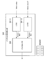
- FIG. 1 is a block diagram illustrating a configuration of a communication device 1 according to an embodiment of the present disclosure.
- FIG. 2 is a block diagram illustrating a configuration of the communication apparatus 100 according to the comparative example. Since each structure which the communication apparatus 1 shown in FIG. 1 has is demonstrated in detail later, description here is abbreviate
- the communication device 100 according to the comparative example includes a modulator 210 including a mapping unit 220 that is different from the communication device 1 according to the present embodiment. Note that both the mapping unit 22 and the mapping unit 220 perform mapping using a plurality of modulation schemes based on 16QAM, QPSK, and Pi2 shift BPSK.
- the mapping unit 220 performs mapping so that “the symbol point arrangement is maximized”. For this reason, as shown in FIG. 2, when the transmission power is made constant, it is necessary to adjust the output by adjusting the power of the transmission amplifier included in the analog processing unit 225 according to each modulation method.
- the mapping is performed such that “the average power is the same” by adjusting the symbol arrangement by the mapping unit 22. For this reason, in the communication apparatus 1 according to the present embodiment, as shown in FIG. 1, it is not necessary to adjust the output of the transmission amplifier included in the analog processing unit 25 according to each modulation method. For this reason, the communication apparatus 1 according to the present embodiment can amplify the transmission signal with constant power in the transmission amplifier included in the analog processing unit 25.
- the communication apparatus 1 performs encoding using an LDPC (Low-Density Parity-check Code) code.
- LDPC Low-Density Parity-check Code
- the communication apparatus 1 inserts the pilot sequence for equalization before and after the physical layer service data unit (PSDU: PHY Service Data Unit) in the transmission frame.
- PSDU Physical layer service data unit
- the communication device 1 is provided with a shortened pre-plan and a connection layer service data unit (CSDU: Connection layer Service Data Unit) for the purpose of improving frame utilization efficiency.
- CSDU Connection layer Service Data Unit
- the communication apparatus 1 according to the present embodiment can improve the reception SNR by adopting such a proposed method.
- the communication apparatus 1 according to the present embodiment can provide more stable communication by providing a surplus of the reception SNR, and can secure a margin for performance degradation due to individual variations during mass production.
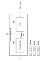
- a communication apparatus includes a communication module 2 and a transmission data generation module 3 as illustrated in FIG.
- the configuration of the communication module 2 according to an embodiment of the present disclosure will be described with reference to FIGS. 1 to 7.
- the communication module 2 includes a modulator 21, a mapping unit 22, a baseband waveform generation unit 23, a frequency conversion unit 24, an analog processing unit 25, and a transmission unit 26.
- Modulator 21 has a function of modulating binary transmission data output from the transmission data generation module 3 into an electric signal. Specifically, the modulator 21 functions as the mapping unit 22 and the baseband waveform generation unit 23.
- mapping unit 22 16QAM / QPSK / Pi2 shift BPSK Mapper
- the mapping unit 22 maps the binary transmission data output from the transmission data generation module 3 to symbol points on the complex plane.
- Table 1 below shows a table summarizing symbol point arrangement by the mapping unit 22 described in detail below.
- FIG. 3 is an explanatory diagram showing the concept of Pi / 2 shift BPSK in the conventional method.
- Pi / 2 shift BPSK is characterized by rotating the transmission axis by 90 degrees (Pi / 2) for each symbol to be transmitted. By such a rotation operation, the envelope of the signal (Envelop) does not pass through the origin of the complex plane at the time of symbol transition, and the design difficulty of the transmission amplifier is reduced.
- the communication apparatus according to the present embodiment employs 16QAM and QPSK in addition to Pi2 shift BPSK, which has been adopted in the conventional method, to increase the transmission speed.
- the communication device according to the present embodiment performs equalization of the signal in the frame by the symbol point arrangement by the mapping unit 22.
- the mapping unit 22 uses a symbol point having the same average power among a plurality of predetermined modulation schemes in each modulation scheme, and modulates transmission data with any one of the plurality of predetermined modulation schemes. Functions as a modulation unit.
- the mapping unit 22 performs modulation using at least one of 16QAM, QPSK, and BPSK as a plurality of predetermined modulation schemes.
- the mapping unit 22 performs modulation using symbol points in 16QAM in any of the plurality of modulation schemes.
- symbol points in 16QAM will be described with reference to FIG.
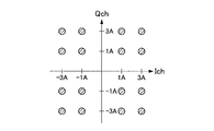
- FIG. 4 is a diagram showing a 16QAM symbol point arrangement according to the present embodiment.
- the symbol points are (A + jA), (A + j3A), (3A + jA), (3A + j3A), (A ⁇ jA), (A ⁇ j3A), (3A ⁇ jA), (3A ⁇ ).
- A is an arbitrary value and indicates the normalized amplitude of the transmission power. Table 2 below shows the power at each symbol point of 16QAM shown in FIG.
- the power of the symbol point (A + jA) is 2A 2
- the power of the symbol point (3A + j3A) is 18A 2
- mapping section 22 modulates using these symbol points that have the same power as the average power of 16QAM. Since the mapping unit 22 performs mapping using only symbol points with power 10A 2 in QPSK and BPSK, the average power is naturally 10A 2 . Therefore, in 16QAM, QPSK, and BPSK, the average power of the symbol points is the same.
- symbol point arrangement in QPSK will be described with reference to FIG.
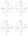
- FIG. 5 is a diagram showing a QPSK symbol point arrangement according to the present embodiment.
- the symbol point arrangement A first symbol point set shown in FIG. 5A includes symbol points (3A + jA), ( ⁇ A + j3A), ( ⁇ 3A ⁇ jA), and (A ⁇ j3A).
- the symbol point arrangement B second symbol point set shown in FIG. 5B includes symbol points (A + j3A), ( ⁇ 3A + jA), ( ⁇ A ⁇ j3A), and (3A ⁇ jA).
- the mapping unit 22 modulates using at least one of these two symbol point arrangements.
- the mapping unit 22 performs modulation by alternately using the symbol point arrangement A and the symbol point arrangement B every other symbol. That is, the mapping unit 22 performs modulation while rotating the transmission axis for each symbol to be transmitted. By such a rotation operation, the envelope of the signal does not pass through the origin of the complex plane at the time of symbol transition, and the design difficulty of the transmission amplifier is alleviated. Note that the mapping unit 22 may modulate using either the symbol point arrangement A or the symbol point arrangement B continuously. Next, the symbol point arrangement in QPSK will be described with reference to FIG.
- FIG. 6 is a diagram showing a symbol point arrangement of BPSK according to the present embodiment.
- the symbol constellation average power is 10A 2 is, 6A, 6B, 6C, there are four types shown in FIG. 6D.
- the symbol point arrangement A (third symbol point set) shown in FIG. 6A includes symbol points (A + j3A) and ( ⁇ A ⁇ j3A).
- the symbol point arrangement B (fourth symbol point set) shown in FIG. 6B includes symbol points ( ⁇ 3A + jA) and (3A ⁇ jA).
- the symbol point arrangement C (fifth symbol point set) shown in FIG. 6C includes symbol points ( ⁇ A + j3A) and (A ⁇ j3A).
- the symbol point arrangement D (sixth symbol point set) shown in FIG. 6D includes symbol points (3A + jA) and ( ⁇ 3A ⁇ jA).
- mapping section 22 modulates using at least one of these four symbol point arrangements.
- the combination of the symbol point arrangements A and B and the combination of the symbol point arrangements C and D are respectively shifted by 90 degrees.
- other combinations such as the symbol point arrangements A and C and the symbol point arrangements A and D have a deviation of 90 degrees or less, and are considered meaningless in terms of symbol point design.
- the mapping unit 22 modulates using the symbol point arrangement A and the symbol point arrangement B alternately every other symbol, or using the symbol point arrangement C and the symbol point arrangement D alternately every other symbol. That is, the mapping unit 22 performs modulation while rotating the transmission axis by 90 degrees for each symbol to be transmitted. By such a rotation operation, the envelope of the signal does not pass through the origin of the complex plane at the time of symbol transition, and the design difficulty of the transmission amplifier is alleviated. Furthermore, as described above, in the conventional method as well, since modulation is performed by BPSK while rotating the transmission axis by 90 degrees, the communication device 1 according to the present embodiment ensures compatibility with the conventional method. be able to. Note that the mapping unit 22 may modulate using any one of the symbol point arrangements A, B, C, and D continuously.
- the mapping unit 22 outputs a complex sequence obtained by mapping the binary transmission data output from the transmission data generation module 3 on the complex plane to the baseband waveform generation unit 23.
- the average power could be made the same in QPSK and BPSK.
- the modulator 21 may employ other modulation schemes such as 64QAM and 256QAM, but in other modulation schemes, there may be no symbol point having the same power as the average power. In this case, the modulator 21 can make the average power the same in each modulation scheme by using an approximate symbol or a DAC (Digital-to-Analog Converter) having a high normal resolution.
- DAC Digital-to-Analog Converter
- the baseband waveform generation unit 23 has a function of generating a baseband waveform based on the series output from the mapping unit 22.
- the baseband waveform generation unit 23 according to the present embodiment generates a baseband waveform using the waveform shown in FIG. 7 that has been used in the conventional method.
- FIG. 7 is a diagram illustrating a baseband waveform used by the communication device 1 according to the present embodiment. As shown in FIG. 7, the waveform period is represented by normalized 8 samples shown along the horizontal axis, and is the reciprocal 1 / Rs of the symbol rate Rs. Table 3 below shows the amplitude value of the transmission waveform shown in FIG.
- the baseband waveform generation unit 23 outputs the generated baseband waveform to the frequency conversion unit 24.
- the frequency conversion unit 24 has a function of performing frequency conversion on the transmission target signal output from the modulator 21. For example, the frequency conversion unit 24 performs frequency conversion with the center frequency set to 4.48 GHz in accordance with the TransferJet standard. The frequency conversion unit 24 outputs the frequency-converted transmission target signal to the analog processing unit 25.
- the analog processing unit 25 has a function of performing various signal processing on the transmission target signal output from the frequency conversion unit 24.
- the analog processing unit 25 includes a transmission amplifier (amplification unit: TxAmp) and amplifies the transmission target signal output from the frequency conversion unit 24.
- TxAmp transmission amplifier
- the mapping unit 22 since the mapping unit 22 performs mapping so that the average power is the same in any of 16QAM, QPSK, and BPSK, the transmission amplifier needs to adjust the amplification amount according to the modulation scheme. Absent. That is, the transmission amplifier performs amplification with constant power regardless of the modulation method.
- the analog processing unit 25 may include a band-pass filter (BPF: Band-pass filter) and an antenna switch (SW). The analog processing unit 25 outputs a signal obtained by performing these various signal processings to the transmission unit 26.
- BPF Band-pass filter
- SW antenna switch
- the transmission unit 26 has a function of transmitting the transmission signal (transmission data) output from the analog processing unit 25 by proximity wireless communication.
- the transmission unit 26 is configured by an inductive electric field coupling coupler, and performs close proximity wireless communication with an external device according to the TransferJet standard. More specifically, the transmission unit 26 performs close proximity wireless communication with another communication device (communication device having a close proximity wireless communication function) existing within a predetermined communication range from the transmission unit 26.
- the close proximity wireless communication between the transmission unit 26 and another communication device is possible only when the transmission unit 26 and the other communication device are in a close proximity state.
- the proximity state here means, for example, a state in which the distance between the transmission unit 26 and another communication device approaches or contacts within a predetermined range (for example, 3 cm).
- the configuration of the communication module 2 according to this embodiment has been described above. Next, the configuration of the transmission data generation module 3 will be described with reference to FIGS.
- FIG. 8 is a block diagram illustrating a configuration of the communication device 1 according to the present embodiment.
- the transmission data generation module 3 includes a PSDU generation unit 31, a CSDU insertion unit 32, an encoding unit 33, a pilot sequence insertion unit 34, a communication scheme setting unit 35, and a preamble insertion unit 36.
- the transmission data generation module 3 generates PSDU as transmission data and outputs it to the communication module 2.
- PSDU generation unit 31 has a function of generating transmission data (PSDU) to be output to the communication module 2. More specifically, the PSDU generation unit 31 generates a part of the PSDU that is not changed from the conventional system, and generates a PSDU by combining a part related to the proposed system output from the CSDU insertion unit 32 and the like described later.
- the PSDU generation unit 31 may generate a conventional PSDU, and the CSDU insertion unit 32 or the like may change a part thereof to generate the PSDU according to the proposed method.
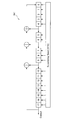
- the conventional scheme and the PSDU frame format in this embodiment will be described with reference to FIG. 9 and FIG.
- FIG. 9 is a diagram showing a frame format of a conventional PSDU.
- a conventional PSDU has a configuration in which a physical layer payload follows a preamble (preamble), a sync (synchronization), and a PHY header (physical layer header).
- the physical layer payload has two sets of Common CNL Header (connection layer common header), Sub CNL Header (connection layer subheader), 0 to 4 KB CSDU, and FCS (frame check sequence).
- the physical layer header includes a 4-bit length field (Version) describing version information of the communication method, a 4-bit length field (Rate) describing the communication rate, and an 8-bit length reservation. It has a field (Reserved), a 16-bit field (Length) describing information on the length of the PSDU, and a 16-bit field (HCS) describing a header check sequence for the physical layer header.
- Version 4-bit length field
- Rate 4-bit length field
- HCS 16-bit field
- FIG. 10 is a diagram showing a frame format of PSDU according to the present embodiment.
- a portion different from the conventional method is hatched in the PSDU frame format according to the present embodiment.
- the proposed method there are changes in the preamble, version field, rate field, and reserved field. Also, Pilot Sequence and Postamble are added. Furthermore, the number of sets of Sub CNL Header, CSDU and FCS is increasing. A detailed description of parts different from these conventional methods will be given together with the description of the CSDU insertion unit 32, the encoding unit 33, the pilot sequence insertion unit 34, the communication method setting unit 35, or the preamble insertion unit 36.
- the CSDU insertion unit 32 has a function of inserting two or more connection layer service data units (CSDUs) into a physical layer service data unit (PSDU).
- the CSDU insertion unit 32 can reduce the amount of overhead required to transmit a certain number of CSDUs by inserting two or more CSDUs into the PSDU, and can improve the throughput.
- the CSDU insertion unit 32 can set the number of CSDUs in the Common CNL Header to 2 or more.
- the upper limit of the length of PSDU in the conventional method is up to the length that can be represented by 16 bits of the Length field in the PHY Header.
- the number of CSDUs can be two or more, 8 bits of the Reserved field are newly used as Length.
- the upper limit of the length of the PSDU is expanded, and a maximum length of 24 bits can be supported.
- the encoding unit 33 has a function of encoding transmission data with an LDPC code.
- the encoding unit 33 performs encoding using the parity check matrix of the LDPC code shown in Table 4 below. As shown in Table 4, the encoding unit 33 uses encoding rates represented by 14/15, 13/15, and 11/15.
- the encoding unit 33 can compensate for the SNR required for multi-leveling by performing encoding using an LDPC code.
- the encoding unit 33 may encode the transmission data using a Reed-Solomon code or a Viterbi code that has been used in the conventional method.
- the pilot sequence insertion unit 34 has a function of inserting a pilot sequence into transmission data. More specifically, as shown in FIG. 10, the pilot sequence insertion unit 34 inserts pilot sequences and postamblles that are pilot sequences so as to sandwich the end of the packet from the common CNL header. The pilot sequence insertion unit 34 inserts the pilot sequence into the transmission frame, so that the reception side can easily perform signal processing by an equalizer or the like, so that the reception SNR required by multi-leveling such as 16QAM can be obtained. Can be improved.
- the Pilot Sequence and the Postamble are modulated by the modulation method described in the Rate field of the PHY Header.
- the internal configuration of the pilot sequence insertion unit 34 will be described with reference to FIG.
- FIG. 11 is a diagram showing an internal configuration of the pilot sequence insertion unit 34 according to the present embodiment.
- the pilot sequence insertion unit 34 includes an LFSR (Linear Feedback Shift Register) 341 and a bit selector 342.
- LFSR Linear Feedback Shift Register
- the LFSR 341 functions as a scramble sequence generation unit that generates a scramble sequence for spread spectrum.
- the scramble sequence generated by the LFSR 341 is used for spread spectrum of the transmission signal both in the conventional method and in the present embodiment.
- the scramble sequence generated by the LFSR 341 is reused for the generation of the pilot sequence by the pilot sequence insertion unit 34.
- the LFSR 341 will be described in detail with reference to FIG.
- FIG. 12 is a diagram showing an internal configuration of the LFSR 341 according to the present embodiment. As shown in FIG. 12, the LFSR 341 generates a binary random number sequence called an M sequence based on a generator polynomial expressed by the following Equation 1.
- the scrambled sequence obtained in the LFSR and the inverted XOR of the transmission signal are obtained for the entire Preamble, Header, and Payload packets to obtain the final transmission signal.
- the communication device 1 obtains an inverted XOR of a scramble sequence and a transmission signal for the entire packet, and sets it as a final transmission signal.
- Bit selector 342 has a function of selecting the same number of bits as the number of bits per symbol in the modulation scheme used by the modulator 21 from the scrambled sequence generated by the LFSR 341 and making it a pilot sequence.
- the number of bits per symbol is 4 for 16QAM, 2 for QPSK, and 1 for BPSK. Therefore, if the scramble sequence generation unit 341 always generates a 4-bit sequence as shown in FIG. 11, the bit selector 342 has all 4 bits when the modulation method is 16QAM, 2 bits when QPSK, In the case of BPSK, 1 bit is selected.
- bit selector 342 selects the first two bits in the case of QPSK and the first one bit in the case of BPSK, the bit selector 342 may select from other arbitrary positions.
- the scramble sequence selected by the bit selector 342 becomes a Pilot Sequence or a Postamble.
- the modulator 21 can employ
- an internal configuration of a pilot sequence insertion unit when modulator 21 adopts 64QAM will be described with reference to FIG.
- FIG. 13 is a diagram showing an internal configuration of pilot sequence insertion section 340 according to the reference mode.
- pilot sequence insertion section 340 generates two 6-bit random symbols by using two LFSRs 341 that output a 4-bit sequence.
- the bit selector 342 generates a 6-bit random number symbol by selecting 2 bits out of the 4 bits output from the LFSR 341-1 and the 4 bits output from the LFSR 341-2.
- the bit selector 342 selects the first 2 bits as in the case of QPSK.
- the initial values used for the LFSRs 341-1 and 341-2 are different from each other.
- the communication method setting unit 35 has a function of setting information for notifying the receiving side of the communication method in the PSDU. Specifically, the communication method setting unit 35 sets information indicating the communication method in the Rate field and the Version field of the PHY Header.
- the communication system setting unit 35 sets information (any value from 0x1 to 0xA) indicating the modulation system and the transmission rate in the Rate field.
- Table 5 shows combinations of modulation schemes and transmission rates employed by the communication apparatus 1 according to the present embodiment.
- Rate 32 to Rate 522 is a combination of a modulation method and a transmission rate in the conventional method.
- the communication apparatus 1 according to the present embodiment newly adopts five types of rates of Rate 2088, Rate 1641, Rate 1044, Rate 820, and Rate 410 as proposed schemes using LDPC code, QPSK, or 16QAM.
- the communication method setting unit 35 assigns numbers from 0x6 to 0xA, which have not been used in the conventional method, to five new rates in the Rate field.
- FIG. 14 is a conceptual diagram showing the BER (bit error rate) characteristics of the conventional method and the proposed method.
- the receiving side can also demodulate signals modulated by the conventional method.
- the transmission side can always transmit at a free transmission rate.
- the transmission side determines the transmission rate using an algorithm that increases the transmission rate when the SNR at the reception side is high and decreases the transmission rate when the SNR is low.
- the communication apparatus 1 according to the present embodiment also employs this algorithm, and first increases the transmission rate from the bottom to the top according to the communication status, such as Rate 32 and then Rate 65.
- the communication status such as Rate 32 and then Rate 65.
- the communication device 1 uses the Rate 410 by skipping the Rate 522 after the Rate 261 when communicating with a terminal capable of communication using the proposed method. Thereby, the communication apparatus 1 which concerns on this embodiment can adjust a transmission rate efficiently.
- the communication method setting unit 35 sets a value of “0x2” in the Version field (4 bits) in the PHY Header.
- the receiving side can identify whether the communication is related to the conventional method or the communication related to the proposed method.
- the communication apparatus 1 can also apply the conventional method to the communication module 2 and apply this embodiment to the transmission data generation module 3. Specifically, the communication apparatus 1 sets “0x2” to the version from Rate 32 to Rate 522, inserts two or more CSDUs and pilot sequences, and transmits a PSDU frame having a shortened preamble.
- the preamble, sync, and PHY header shown in FIG. 10 are modulated with Pi / 2 shift BPSK. It shall be.
- data from Pilot Sequence to Postamble is modulated by the modulation scheme described in the Rate field.
- the preamble insertion unit 36 has a function of inserting a preamble having a length from 7.28 usec to 0 usec into the PSDU.
- the preamble insertion unit 36 shortens the length of the preamble, which was 7.28 usec in the conventional method.
- the preamble insertion unit 36 can freely set the length between 7.28 usec and 0 usec. Thereby, since the length of the whole PSDU is reduced, the transmission speed can be increased. Furthermore, by reducing the length of the preamble, frame utilization efficiency is improved and throughput is improved.
- the preamble is used as a preparation signal before reception for gain adjustment on the reception side. In close proximity wireless communication such as TransferJet, since the transmission power is small, the pull-in time for gain adjustment can be shortened, and as a result, the preamble can be shortened.
- the configuration of the transmission data generation module 3 according to the present embodiment has been described above. Next, the operation process of the communication device 1 will be described with reference to FIG.
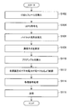
- FIG. 15 is a flowchart showing the operation of the communication apparatus 1 according to this embodiment.
- the communication apparatus 1 inserts a CSDU frame. More specifically, the CSDU insertion unit 32 inserts the CSDU into the PSDU generated by the PSDU generation unit 31. At this time, the CSDU insertion unit 32 can insert two or more CSDUs.
- step S104 the communication device 1 performs LDPC encoding. More specifically, the encoding unit 33 performs LDPC encoding on the transmission data using one of the parity check matrices shown in Table 4 above.
- step S106 the communication device 1 inserts a pilot sequence. More specifically, the pilot sequence insertion unit 34 inserts Pilot Sequence and Postamble, which are pilot sequences, so as to sandwich the end of the packet from the Common CNL Header.
- step S108 the communication device 1 sets a communication method. More specifically, the communication method setting unit 35 sets information indicating the communication method in the Rate field and the Version field of the PHY header.
- step S110 the communication device 1 inserts a preamble. More specifically, the preamble insertion unit 36 inserts a preamble having a length of 7.28 usec to 0 usec in the PSDU.
- the communication device 1 modulates the transmission data so that the average power becomes the same in each modulation scheme. More specifically, the mapping unit 22 first maps binary transmission data output from the transmission data generation module 3 to symbol points on the complex plane. At this time, the mapping unit 22 arranges symbol points in each modulation scheme so that the average power is the same between 16QAM, QPSK, and BPSK. More specifically, the mapping unit 22 uses the symbol point arrangement shown in FIG. 4 for 16QAM, FIG. 5 for QPSK, and FIG. 6 for BPSK. Subsequently, based on the series output from the mapping unit 22, the baseband waveform generation unit 23 generates a baseband waveform using the waveform shown in FIG.
- step S114 the communication device 1 performs various signal processing on the transmission signal. More specifically, the frequency converting unit 24 converts the frequency of the transmission signal, and the analog processing unit 25 amplifies the frequency-converted transmission signal or applies a bandpass filter. In step S112, the mapping is performed so that the average power is the same in any of 16QAM, QPSK, and BPSK. Therefore, the transmission amplifier included in the analog processing unit 25 amplifies the transmission signal with constant power.
- step S118 the communication device 1 transmits a transmission signal. More specifically, the transmission unit 26 transmits the transmission signal output from the analog processing unit 25 by proximity wireless communication.
- the communication device 1 can realize higher-speed transmission by converting the transmission signal into multiple values.
- the communication device 1 realizes amplification at a constant power in the transmission amplifier by performing equal power by symbol point arrangement with respect to variations in the power of the signal in the frame caused by multi-leveling, and the amplification amount Control can be dispensed with.
- the communication apparatus 1 according to the present embodiment employs various communication methods that improve the reception SNR and reception EVM, thereby enabling more stable communication and margins for performance degradation due to individual variations during mass production. Can be secured.
- the present technology is not limited to such an example in which the communication device 1 performs close proximity wireless communication in accordance with the TransferJet standard.
- the communication device 1 may communicate with an external device via Bluetooth (registered trademark), Zigbee (registered trademark), or UWB (Ultra Wide Band).
- a communication apparatus comprising: a modulation unit that uses a symbol point having the same average power among a plurality of predetermined modulation schemes in each modulation scheme, and modulates transmission data by one of the plurality of predetermined modulation schemes.
- the modulation unit modulates using a symbol point in 16QAM in any of the predetermined plurality of modulation schemes, and modulates using a symbol point having the same power as the average power of 16QAM in a modulation scheme other than 16QAM.
- the communication device according to (1).
- the modulation unit First symbol point set including symbol points (3A + jA), ( ⁇ A + j3A), ( ⁇ 3A ⁇ jA), (A ⁇ j3A), or symbol points (A + j3A), ( ⁇ 3A + jA), ( ⁇ A ⁇ j3A)
- the modulation unit includes a third symbol point set including symbol points (A + j3A) and ( ⁇ A ⁇ j3A), a fourth symbol point including (3A + jA) and (3A ⁇ jA).
- At least one of a symbol point set, a fifth symbol point set including symbol points ( ⁇ A + j3A) and (A ⁇ j3A), and a sixth symbol point set including symbol points (3A + jA) and ( ⁇ 3A ⁇ jA) The communication device according to (3) or (4), wherein modulation is performed using (6)
- the modulation unit modulates the third symbol point set and the fourth symbol point set alternately or alternatively uses the fifth symbol point set and the sixth symbol point set alternately;
- the communication apparatus according to any one of (1) to (7), further including a transmission unit configured to transmit the transmission data by proximity wireless communication.
- the communication apparatus according to any one of (1) to (8), further including an encoding unit that encodes the transmission data using an LDPC code.
- the communication device A scramble sequence generator for generating a scramble sequence for spread spectrum; A pilot sequence insertion unit for inserting a pilot sequence into the transmission data; Further comprising The pilot sequence insertion unit selects the same number of bits as the number of bits per symbol in the modulation scheme used by the modulation unit from the scramble sequence generated by the scramble sequence generation unit, and forms the pilot sequence.
- the communication device according to any one of (9).
- the communication apparatus further includes a CSDU insertion unit that inserts two or more connection layer service data units (CSDUs) into a physical layer service data unit (PSDU).
- CSDUs connection layer service data units
- the communication apparatus as described in. (12) The communication apparatus according to any one of (1) to (11), further including a preamble insertion unit that inserts a preamble having a length of 7.28 usec to 0 usec in the transmission data. . (13)
- a communication method comprising: using symbol points having the same average power among a plurality of predetermined modulation schemes in each modulation scheme, and modulating transmission data by any one of the plurality of predetermined modulation schemes.
Abstract
Description
1.本開示の一実施形態に係る通信装置の概要
2.実施形態
2-1.通信モジュールの構成
2-2.送信データ生成モジュールの構成
2-3.動作処理
3.まとめ The description will be made in the following order.
1. 1. Overview of communication apparatus according to an embodiment of the present disclosure Embodiment 2-1. Configuration of communication module 2-2. Configuration of transmission data generation module 2-3. 2. Operation processing Summary
本開示の一実施形態に係る通信装置は、TransferJetコンソーシアム(非特許文献1)、ECMA-398(非特許文献2)において規定された通信処理を改良した通信処理を行う。以下では、TransferJetコンソーシアム(非特許文献1)、ECMA-398(非特許文献2)において規定された通信処理を従来方式とも称し、本実施形態で改良した通信処理を提案方式とも称する。 <1. Overview of Communication Device According to One Embodiment of Present Disclosure>
A communication apparatus according to an embodiment of the present disclosure performs communication processing improved from the communication processing defined in TransferJet Consortium (Non-Patent Document 1) and ECMA-398 (Non-Patent Document 2). Hereinafter, the communication process defined in the TransferJet Consortium (Non-Patent Document 1) and ECMA-398 (Non-Patent Document 2) is also referred to as a conventional method, and the communication process improved in the present embodiment is also referred to as a proposed method.
本開示の一実施形態に係る通信装置は、図1に示したように、通信モジュール2および送信データ生成モジュール3を有する。以下、まず、図1~図7を参照して、本開示の一実施形態に係る通信モジュール2の構成を説明する。
[2-1.通信モジュールの構成]
図1に示すように、通信モジュール2は、変調器21、マッピング部22、ベースバンド波形生成部23、周波数変換部24、アナログ処理部25、および送信部26を有する。 <2. Embodiment>
A communication apparatus according to an embodiment of the present disclosure includes a
[2-1. Configuration of communication module]
As illustrated in FIG. 1, the
変調器21は、送信データ生成モジュール3から出力されたバイナリの送信データを電気信号に変調する機能を有する。具体的には、変調器21は、マッピング部22およびベースバンド波形生成部23として機能する。 (Modulator 21: Modulator)
The
マッピング部22は、送信データ生成モジュール3から出力されたバイナリの送信データを、複素平面上のシンボル点にマッピングする。下記表1に、以下に詳しく説明するマッピング部22によるシンボル点配置についてまとめた表を示す。 (Mapping unit 22: 16QAM / QPSK / Pi2 shift BPSK Mapper)
The


本実施形態では、16QAMの平均電力と同一電力のシンボル点があったために、QPSKやBPSKにおいても平均電力を同一にすることができた。変調器21は、64QAMや256QAMなどの他の変調方式を採用し得るが、他の変調方式においては平均電力と同一電力のシンボル点が無い場合も考えられる。この場合、変調器21は、近似シンボルまたは通常の分解能が高いDAC(Digital-to-Analog Converter)を使うことにより、各変調方式において平均電力を同一にすることができる。 -Supplement In this embodiment, since there was a symbol point having the same power as the average power of 16QAM, the average power could be made the same in QPSK and BPSK. The
ベースバンド波形生成部23は、マッピング部22から出力された系列に基づいてベースバンド波形を生成する機能を有する。本実施形態に係るベースバンド波形生成部23は、従来方式で用いられてきた、図7に示す波形を用いてベースバンド波形を生成する。図7は、本実施系形態に係る通信装置1が用いるベースバンド波形を示す図である。図7に示すように、波形の周期は、横軸に沿って示される正規化された8サンプルで表され、シンボルレートRsの逆数1/Rsである。なお、下記の表3に、図7に示した送信波形の振幅値を示した。 (Baseband waveform generator 23: Baseband Waveform Generator)
The baseband

周波数変換部24は、変調器21から出力された送信対象信号を周波数変換する機能を有する。例えば、周波数変換部24は、TransferJet規格に準じて、中心周波数を4.48GHzとする周波数変換を行う。周波数変換部24は、周波数変換した送信対象信号を、アナログ処理部25に出力する。 (Frequency converter 24: Up Converter)
The
アナログ処理部25は、周波数変換部24から出力された送信対象信号に対して各種信号処理を行う機能を有する。例えば、アナログ処理部25は、送信アンプ(増幅部:TxAmp)を有し、周波数変換部24から出力された送信対象信号を増幅する。ここで、上述したように、マッピング部22において、16QAM、QPSK、BPSKのいずれにおいても平均電力が同じになるようマッピングされるため、送信アンプは、変調方式に応じて増幅量を調整する必要がない。即ち、送信アンプは、変調方式にかかわらず、一定電力で増幅を行う。他にも、アナログ処理部25は、バンドパスフィルタ(BPF:Band-pass filter)、アンテナスイッチ(SW)を有していてもよい。アナログ処理部25は、これらの各種信号処理を行った信号を送信部26に出力する。 (Analog processing unit 25: BPF, Amp & SW)
The
送信部26は、アナログ処理部25から出力された送信信号(送信データ)を、近接無線通信により送信する機能を有する。例えば、送信部26は、誘導電界結合型カプラにより構成され、TransferJet規格に準じて外部機器との間で近接無線通信を行う。より詳しくは、送信部26は、送信部26から所定の通信範囲内に存在する他の通信装置(近接無線通信機能を備える通信装置)との間で近接無線通信を行う。ここで、送信部26と他の通信装置との間の近接無線通信は、送信部26と他の通信装置とが近接状態である場合にのみ可能となる。ここでの近接状態とは、例えば、送信部26と他の通信装置との間の距離が所定範囲(例えば、3cm)以内に接近または接触している状態を意味する。 (Transmitter 26: Coupler)
The
図8は、本実施形態に係る通信装置1の構成を示すブロック図である。図8に示すように、送信データ生成モジュール3は、PSDU生成部31、CSDU挿入部32、符号化部33、パイロット系列挿入部34、通信方式設定部35、およびプリアンブル挿入部36を有する。送信データ生成モジュール3は、送信データとしてPSDUを生成して、通信モジュール2に出力する。 [2-2. Configuration of transmission data generation module 3]
FIG. 8 is a block diagram illustrating a configuration of the
PSDU生成部31は、通信モジュール2に出力する送信データ(PSDU)を生成する機能を有する。より詳しくは、PSDU生成部31は、PSDUのうち従来方式から変更がない部分について生成し、後述のCSDU挿入部32等から出力等された提案方式に係る部分を組み合わせて、PSDUを生成する。なお、PSDU生成部31が従来方式のPSDUを生成して、CSDU挿入部32等がその一部を変更することで、提案方式に係るPSDUを生成する形態であってもよい。以下、図9および図10を参照して、従来方式および本実施形態におけるPSDUフレームフォーマットを説明する。 (PSDU generator 31)
The
CSDU挿入部32は、物理層サービスデータユニット(PSDU)の中に2以上の接続層サービスデータユニット(CSDU)を挿入する機能を有する。CSDU挿入部32は、2以上のCSDUをPSDUに挿入することにより、ある個数のCSDUの送信に必要なオーバヘッド量を低減することができ、スループットを向上させることができる。 (CSDU insertion part 32)
The
符号化部33は、送信データをLDPC符号により符号化する機能を有する。符号化部33は、下記表4に示すLDPC符号のパリティ検査行列を用いて符号化を行う。符号化部33は、表4に示すように、14/15、13/15、11/15で表される符号化率を用いる。符号化部33は、LDPC符号による符号化を行うことで、多値化によって必要となるSNRを補償することができる。なお、符号化部33は、従来方式において用いられてきたReed-Solomon符号またはViterbi符号により、送信データを符号化してもよい。 (Encoding unit 33)
The

パイロット系列挿入部34は、パイロット系列を送信データに挿入する機能を有する。より詳しくは、パイロット系列挿入部34は、図10に示すように、Common CNL Headerからパケットの終端を挟み込むように、パイロット系列であるPilot SequenceおよびPostambleの挿入を行う。パイロット系列挿入部34は、送信フレームにパイロット系列を挿入することにより、受信側は等化器などによる信号処理を容易に実現可能となるので、16QAMなどの多値化により必要となる受信SNRを向上させることができる。なお、Pilot SequenceおよびPostambleは、PHY HeaderのRateフィールドに記載された変調方式で変調される。以下、図11を参照して、パイロット系列挿入部34の内部構成を説明する。 (Pilot sequence insertion unit 34)
The pilot
LFSR341は、スペクトラム拡散のためのスクランブル系列を発生するスクランブル系列発生部として機能する。LFSR341により発生したスクランブル系列は、従来方式においても、本実施形態においても、送信信号のスペクトラム拡散のために使用される。本実施形態では、パイロット系列挿入部34によるパイロット系列の生成のために、LFSR341が発生したスクランブル系列を再利用する。以下、図12を参照して、LFSR341について詳細に説明する。 ・ LFSR341
The

ビットセレクタ342は、LFSR341により発生されたスクランブル系列から、変調器21が用いる変調方式における1シンボルあたりのビット数と同数のビットを選択して、パイロット系列とする機能を有する。1シンボルあたりのビット数は、16QAMの場合は4、QPSKの場合は2、BPSKの場合は1である。そこで、スクランブル系列発生部341が、図11に示すように常に4ビットの系列を生成するものとすると、ビットセレクタ342は、変調方式が16QAMの場合は4ビットすべて、QPSKの場合は2ビット、BPSKの場合は1ビットを選択する。図11では、ビットセレクタ342が、QPSKの場合は前半2ビット、BPSKの場合は先頭の1ビットを選択する例を示したが、他の任意の位置から選択してもよい。ビットセレクタ342により選択されたスクランブル系列が、Pilot SequenceまたはPostambleとなる。
The
上述したように、変調器21は、変調方式として64QAMや256QAMなども採用し得る。ここでは参考形態として、変調器21が64QAMを採用した場合のパイロット系列挿入部の内部構成を、図13を参照して説明する。 -Supplement As above-mentioned, the
通信方式設定部35は、通信方式を受信側に通知するための情報を、PSDUに設定する機能を有する。具体的には、通信方式設定部35は、PHY HeaderのRateフィールドおよびVersionフィールドに、通信方式を示す情報を設定する。 (Communication method setting unit 35)
The communication
通信方式設定部35は、Rateフィールドに、変調方式および伝送レートを示す情報(0x1から0xAまでのいずれかの値)を設定する。表5に本実施形態に係る通信装置1が採用する変調方式および伝送レートの組み合わせを示す。 -RATE field The communication

通信方式設定部35は、PHY Headerの中のVersionフィールド(4ビット)に、「0x2」の値を設定する。従来方式では、「0x1」の値が用いられているため、受信側は、従来方式に係る通信であるか提案方式に係る通信であるかを識別可能である。なお、通信装置1は、通信モジュール2には従来方式を適用し、送信データ生成モジュール3には本実施形態を適用することも可能である。具体的には、通信装置1は、Rate32からRate522においてVersionに「0x2」を設定して、2個以上のCSDUおよびパイロット系列を挿入し、且つ短縮されたPreambleを有するPSDUフレームを送信する。なお、Versionが「0x2」のパケットにおいても、即ち変調器21による変調方式が16QAMやQPSKであっても、図10に示したPreamble、Sync、 PHY HeaderまではPi/2 shift BPSKで変調されているものとする。一方、Pilot SequenceからPostambleまでのデータは、Rateフィールドに記載された変調方式で変調される。 About Version Field The communication
プリアンブル挿入部36は、PSDUに長さが7.28usecから0usecまでの間のプリアンブルを挿入する機能を有する。プリアンブル挿入部36は、従来方式7.28usecであったプリアンブルの長さを短縮する。プリアンブル挿入部36は、7.28usecから0usecまでの間で、自由に長さを設定可能である。これにより、PSDU全体の長さが縮まるため、伝送速度を速めることができる。さらに、プリアンブルの長さが短縮されることにより、フレーム利用効率が向上し、スループットが向上する。なお、プリアンブルは受信前の準備信号として、受信側でのゲイン調整に用いられる。TransferJetのような近接無線通信では送信電力が少ないため、ゲイン調整のための引き込み時間が短縮可能となり、その結果プリアンブルの短縮が可能となる。 (Preamble insertion part 36)
The
図15は、本実施形態に係る通信装置1の動作を示すフローチャートである。図15に示すように、まず、ステップS102で、通信装置1は、CSDUフレームを挿入する。より詳しくは、CSDU挿入部32は、PSDU生成部31が生成したPSDUの中にCSDUを挿入する。このとき、CSDU挿入部32は、2以上のCSDUを挿入可能である。 [2-3. Operation processing]
FIG. 15 is a flowchart showing the operation of the
以上説明したように、本実施形態に係る通信装置1は、送信信号を多値化することで、より高速な伝送を実現することができる。また、通信装置1は、多値化により生じるフレーム内の信号の電力にバラつきに対し、シンボル点配置によって等電力化を行うことで、送信アンプにおける一定電力での増幅を実現し、増幅量の制御を不要にすることができる。さらに、本実施形態に係る通信装置1は、受信SNRや受信EVMを向上させる各種通信方式を採用することにより、より安定的な通信を可能にすると共に、量産時の個体バラツキによる性能劣化に対するマージンを確保することができる。 <3. Summary>
As described above, the
(1)
所定の複数の変調方式の間で平均電力が同一となるシンボル点を各変調方式において用い、送信データを前記所定の複数の変調方式のいずれかで変調する変調部を備える、通信装置。
(2)
前記変調部は、前記所定の複数の変調方式のいずれにおいても、16QAMにおけるシンボル点を用いて変調し、16QAM以外の変調方式においては、16QAMの平均電力と同一の電力のシンボル点を用いて変調する、前記(1)に記載の通信装置。
(3)
前記所定の複数の変調方式は、16QAM、QPSK、またはBPSKの少なくともいずれかを含む、前記(1)または(2)に記載の通信装置。
(4)
前記変調部は、変調方式がQPSKの場合、
シンボル点(3A+jA)、(-A+j3A)、(-3A-jA)、(A-j3A)を含む第1のシンボル点集合、またはシンボル点(A+j3A)、(-3A+jA)、(-A-j3A)、(3A-jA)を含む第2のシンボル点集合の少なくともいずれかを用いて変調する、前記(3)に記載の通信装置。
(5)
前記変調部は、変調方式がBPSKの場合、シンボル点(A+j3A)、(-A-j3A)を含む第3のシンボル点集合、シンボル点(-3A+jA)、(3A-jA)を含む第4のシンボル点集合、シンボル点(-A+j3A)、(A-j3A)を含む第5のシンボル点集合、またはシンボル点(3A+jA)、(-3A-jA)を含む第6のシンボル点集合の少なくともいずれかを用いて変調する、前記(3)または(4)に記載の通信装置。
(6)
前記変調部は、前記第1のシンボル点集合および前記第2のシンボル点集合を交互に用いて変調する、前記(4)に記載の通信装置。
(7)
前記変調部は、前記第3のシンボル点集合および前記第4のシンボル点集合を交互に用いて、または前記第5のシンボル点集合および前記第6のシンボル点集合を交互に用いて変調する、前記(5)に記載の通信装置。
(8)
前記通信装置は、前記送信データを近接無線通信により送信する送信部をさらに備える、前記(1)~(7)のいずれか一項に記載の通信装置。
(9)
前記通信装置は、前記送信データをLDPC符号により符号化する符号化部をさらに備える、前記(1)~(8)のいずれか一項に記載の通信装置。
(10)
前記通信装置は、
スペクトラム拡散のためのスクランブル系列を発生するスクランブル系列発生部と、
パイロット系列を前記送信データに挿入するパイロット系列挿入部と、
をさらに備え、
前記パイロット系列挿入部は、前記スクランブル系列発生部により発生された前記スクランブル系列から、前記変調部が用いる変調方式における1シンボルあたりのビット数と同数のビットを選択して前記パイロット系列とする、前記(1)~(9)のいずれか一項に記載の通信装置。
(11)
前記通信装置は、物理層サービスデータユニット(PSDU)の中に2以上の接続層サービスデータユニット(CSDU)を挿入するCSDU挿入部をさらに備える、前記(1)~(10)のいずれか一項に記載の通信装置。
(12)
前記通信装置は、前記送信データに長さが7.28usecから0usecまでの間のプリアンブルを挿入するプリアンブル挿入部をさらに備える、前記(1)~(11)のいずれか一項に記載の通信装置。
(13)
所定の複数の変調方式の間で平均電力が同一となるシンボル点を各変調方式において用い、送信データを前記所定の複数の変調方式のいずれかで変調することを備える、通信方法。 The following configurations also belong to the technical scope of the present disclosure.
(1)
A communication apparatus comprising: a modulation unit that uses a symbol point having the same average power among a plurality of predetermined modulation schemes in each modulation scheme, and modulates transmission data by one of the plurality of predetermined modulation schemes.
(2)
The modulation unit modulates using a symbol point in 16QAM in any of the predetermined plurality of modulation schemes, and modulates using a symbol point having the same power as the average power of 16QAM in a modulation scheme other than 16QAM. The communication device according to (1).
(3)
The communication apparatus according to (1) or (2), wherein the predetermined plurality of modulation schemes include at least one of 16QAM, QPSK, and BPSK.
(4)
When the modulation method is QPSK, the modulation unit
First symbol point set including symbol points (3A + jA), (−A + j3A), (−3A−jA), (A−j3A), or symbol points (A + j3A), (−3A + jA), (−A−j3A) The communication apparatus according to (3), wherein modulation is performed using at least one of the second symbol point set including (3A-jA).
(5)
When the modulation scheme is BPSK, the modulation unit includes a third symbol point set including symbol points (A + j3A) and (−A−j3A), a fourth symbol point including (3A + jA) and (3A−jA). At least one of a symbol point set, a fifth symbol point set including symbol points (−A + j3A) and (A−j3A), and a sixth symbol point set including symbol points (3A + jA) and (−3A−jA) The communication device according to (3) or (4), wherein modulation is performed using
(6)
The communication device according to (4), wherein the modulation unit modulates using the first symbol point set and the second symbol point set alternately.
(7)
The modulation unit modulates the third symbol point set and the fourth symbol point set alternately or alternatively uses the fifth symbol point set and the sixth symbol point set alternately; The communication device according to (5).
(8)
The communication apparatus according to any one of (1) to (7), further including a transmission unit configured to transmit the transmission data by proximity wireless communication.
(9)
The communication apparatus according to any one of (1) to (8), further including an encoding unit that encodes the transmission data using an LDPC code.
(10)
The communication device
A scramble sequence generator for generating a scramble sequence for spread spectrum;
A pilot sequence insertion unit for inserting a pilot sequence into the transmission data;
Further comprising
The pilot sequence insertion unit selects the same number of bits as the number of bits per symbol in the modulation scheme used by the modulation unit from the scramble sequence generated by the scramble sequence generation unit, and forms the pilot sequence. (1) The communication device according to any one of (9).
(11)
The communication apparatus further includes a CSDU insertion unit that inserts two or more connection layer service data units (CSDUs) into a physical layer service data unit (PSDU). The communication apparatus as described in.
(12)
The communication apparatus according to any one of (1) to (11), further including a preamble insertion unit that inserts a preamble having a length of 7.28 usec to 0 usec in the transmission data. .
(13)
A communication method comprising: using symbol points having the same average power among a plurality of predetermined modulation schemes in each modulation scheme, and modulating transmission data by any one of the plurality of predetermined modulation schemes.
2 通信モジュール
21 変調器
22 マッピング部
23 ベースバンド波形生成部
24 周波数変換部
25 アナログ処理部
26 送信部
3 送信データ生成モジュール
31 PSDU生成部
32 CSDU挿入部
33 符号化部
34 パイロット系列挿入部
341 LFSR
342 ビットセレクタ
35 通信方式設定部
36 プリアンブル挿入部 DESCRIPTION OF
342
Claims (13)
- 所定の複数の変調方式の間で平均電力が同一となるシンボル点を各変調方式において用い、送信データを前記所定の複数の変調方式のいずれかで変調する変調部を備える、通信装置。 A communication apparatus including a modulation unit that uses a symbol point having the same average power among a plurality of predetermined modulation schemes in each modulation scheme, and modulates transmission data by any of the plurality of predetermined modulation schemes.
- 前記変調部は、前記所定の複数の変調方式のいずれにおいても、16QAMにおけるシンボル点を用いて変調し、16QAM以外の変調方式においては、16QAMの平均電力と同一の電力のシンボル点を用いて変調する、請求項1に記載の通信装置。 The modulation unit modulates using a symbol point in 16QAM in any of the predetermined plurality of modulation schemes, and modulates using a symbol point having the same power as the average power of 16QAM in a modulation scheme other than 16QAM. The communication device according to claim 1.
- 前記所定の複数の変調方式は、16QAM、QPSK、またはBPSKの少なくともいずれかを含む、請求項1に記載の通信装置。 The communication apparatus according to claim 1, wherein the predetermined plurality of modulation schemes include at least one of 16QAM, QPSK, and BPSK.
- 前記変調部は、変調方式がQPSKの場合、シンボル点(3A+jA)、(-A+j3A)、(-3A-jA)、(A-j3A)を含む第1のシンボル点集合、またはシンボル点(A+j3A)、(-3A+jA)、(-A-j3A)、(3A-jA)を含む第2のシンボル点集合の少なくともいずれかを用いて変調する、請求項3に記載の通信装置。 When the modulation scheme is QPSK, the modulation unit includes a first symbol point set including symbol points (3A + jA), (−A + j3A), (−3A−jA), (A−j3A), or a symbol point (A + j3A) The communication apparatus according to claim 3, wherein modulation is performed using at least one of a second symbol point set including (-3A + jA), (-A-j3A), and (3A-jA).
- 前記変調部は、変調方式がBPSKの場合、シンボル点(A+j3A)、(-A-j3A)を含む第3のシンボル点集合、シンボル点(-3A+jA)、(3A-jA)を含む第4のシンボル点集合、シンボル点(-A+j3A)、(A-j3A)を含む第5のシンボル点集合、またはシンボル点(3A+jA)、(-3A-jA)を含む第6のシンボル点集合の少なくともいずれかを用いて変調する、請求項3に記載の通信装置。 When the modulation scheme is BPSK, the modulation unit includes a third symbol point set including symbol points (A + j3A) and (−A−j3A), a fourth symbol point including (3A + jA) and (3A−jA). At least one of a symbol point set, a fifth symbol point set including symbol points (−A + j3A) and (A−j3A), and a sixth symbol point set including symbol points (3A + jA) and (−3A−jA) The communication apparatus according to claim 3, wherein the communication apparatus modulates the signal using a signal.
- 前記変調部は、前記第1のシンボル点集合および前記第2のシンボル点集合を交互に用いて変調する、請求項4に記載の通信装置。 The communication device according to claim 4, wherein the modulation unit modulates the first symbol point set and the second symbol point set alternately.
- 前記変調部は、前記第3のシンボル点集合および前記第4のシンボル点集合を交互に用いて、または前記第5のシンボル点集合および前記第6のシンボル点集合を交互に用いて変調する、請求項5に記載の通信装置。 The modulation unit modulates the third symbol point set and the fourth symbol point set alternately or alternatively uses the fifth symbol point set and the sixth symbol point set alternately; The communication device according to claim 5.
- 前記通信装置は、前記送信データを近接無線通信により送信する送信部をさらに備える、請求項1に記載の通信装置。 The communication device according to claim 1, further comprising a transmission unit that transmits the transmission data by proximity wireless communication.
- 前記通信装置は、前記送信データをLDPC符号により符号化する符号化部をさらに備える、請求項1に記載の通信装置。 The communication apparatus according to claim 1, further comprising an encoding unit that encodes the transmission data with an LDPC code.
- 前記通信装置は、
スペクトラム拡散のためのスクランブル系列を発生するスクランブル系列発生部と、
パイロット系列を前記送信データに挿入するパイロット系列挿入部と、
をさらに備え、
前記パイロット系列挿入部は、前記スクランブル系列発生部により発生された前記スクランブル系列から、前記変調部が用いる変調方式における1シンボルあたりのビット数と同数のビットを選択して前記パイロット系列とする、請求項1に記載の通信装置。 The communication device
A scramble sequence generator for generating a scramble sequence for spread spectrum;
A pilot sequence insertion unit for inserting a pilot sequence into the transmission data;
Further comprising
The pilot sequence insertion unit selects the same number of bits as the number of bits per symbol in the modulation scheme used by the modulation unit from the scramble sequence generated by the scramble sequence generation unit, and forms the pilot sequence. Item 4. The communication device according to Item 1. - 前記通信装置は、物理層サービスデータユニット(PSDU)の中に2以上の接続層サービスデータユニット(CSDU)を挿入するCSDU挿入部をさらに備える、請求項1に記載の通信装置。 The communication apparatus according to claim 1, further comprising a CSDU insertion unit that inserts two or more connection layer service data units (CSDUs) into a physical layer service data unit (PSDU).
- 前記通信装置は、前記送信データに長さが7.28usecから0usecまでの間のプリアンブルを挿入するプリアンブル挿入部をさらに備える、請求項1に記載の通信装置。 The communication apparatus according to claim 1, further comprising a preamble insertion unit that inserts a preamble having a length of 7.28 usec to 0 usec in the transmission data.
- 所定の複数の変調方式の間で平均電力が同一となるシンボル点を各変調方式において用い、送信データを前記所定の複数の変調方式のいずれかで変調することを備える、通信方法。
A communication method comprising: using symbol points having the same average power among a plurality of predetermined modulation schemes in each modulation scheme, and modulating transmission data by any one of the plurality of predetermined modulation schemes.
Priority Applications (4)
| Application Number | Priority Date | Filing Date | Title |
|---|---|---|---|
| JP2015536481A JPWO2015037342A1 (en) | 2013-09-10 | 2014-07-24 | Communication apparatus and communication method |
| EP14843995.3A EP3046302A4 (en) | 2013-09-10 | 2014-07-24 | Communication apparatus and communication method |
| CN201480048576.3A CN105519068A (en) | 2013-09-10 | 2014-07-24 | Communication apparatus and communication method |
| US14/916,933 US20160218898A1 (en) | 2013-09-10 | 2014-07-24 | Communication device and communication method |
Applications Claiming Priority (2)
| Application Number | Priority Date | Filing Date | Title |
|---|---|---|---|
| JP2013187067 | 2013-09-10 | ||
| JP2013-187067 | 2013-09-10 |
Publications (1)
| Publication Number | Publication Date |
|---|---|
| WO2015037342A1 true WO2015037342A1 (en) | 2015-03-19 |
Family
ID=52665464
Family Applications (1)
| Application Number | Title | Priority Date | Filing Date |
|---|---|---|---|
| PCT/JP2014/069620 WO2015037342A1 (en) | 2013-09-10 | 2014-07-24 | Communication apparatus and communication method |
Country Status (5)
| Country | Link |
|---|---|
| US (1) | US20160218898A1 (en) |
| EP (1) | EP3046302A4 (en) |
| JP (1) | JPWO2015037342A1 (en) |
| CN (1) | CN105519068A (en) |
| WO (1) | WO2015037342A1 (en) |
Citations (7)
| Publication number | Priority date | Publication date | Assignee | Title |
|---|---|---|---|---|
| JPH04208741A (en) * | 1990-11-30 | 1992-07-30 | Tech Res & Dev Inst Of Japan Def Agency | Multivalued orthogonal amplitude modulation circuit |
| JPH09116589A (en) * | 1995-10-17 | 1997-05-02 | Nippon Telegr & Teleph Corp <Ntt> | Multi-valued number variable modem and radio communication equipment |
| JPH1117761A (en) * | 1997-06-24 | 1999-01-22 | Sony Corp | Reception equipment, transmission/reception equipment and communication method |
| JP2002290246A (en) * | 2001-03-28 | 2002-10-04 | Hitachi Kokusai Electric Inc | Transmitter-receiver |
| JP2003078579A (en) * | 2001-07-05 | 2003-03-14 | Alcatel | Method for transmitting frame including burst modulated with different modulation scheme on radio communication channel |
| JP2008227586A (en) * | 2007-03-08 | 2008-09-25 | Toshiba Corp | Transmitter and receiver |
| JP2011139283A (en) * | 2009-12-28 | 2011-07-14 | Sony Corp | Electronic apparatus, and communication device |
Family Cites Families (12)
| Publication number | Priority date | Publication date | Assignee | Title |
|---|---|---|---|---|
| US5852630A (en) * | 1997-07-17 | 1998-12-22 | Globespan Semiconductor, Inc. | Method and apparatus for a RADSL transceiver warm start activation procedure with precoding |
| JP5073512B2 (en) * | 2007-01-19 | 2012-11-14 | パナソニック株式会社 | Multi-antenna transmission apparatus, multi-antenna reception apparatus, multi-antenna transmission method, multi-antenna reception method, terminal apparatus, and base station apparatus |
| WO2008088066A1 (en) * | 2007-01-19 | 2008-07-24 | Panasonic Corporation | Multi-antenna transmission device, multi-antenna reception device, multi-antenna transmission method, multi-antenna reception method, terminal device, and base station device |
| US8102930B2 (en) * | 2007-03-28 | 2012-01-24 | Agere Systems Inc. | Demodulation of 16-QAM, DCM data symbols using two hybrid-QPSK constellations |
| JP5600237B2 (en) * | 2008-02-02 | 2014-10-01 | 学校法人慶應義塾 | Integrated circuit |
| US8050355B2 (en) * | 2008-06-11 | 2011-11-01 | Korea Electronics Technology Institute | Transmitter and receiver using pseudo-orthogonal code |
| WO2010095780A1 (en) * | 2009-02-18 | 2010-08-26 | Lg Electronics Inc. | Apparatus for transmitting and receiving a signal and method of transmitting and receiving a signal |
| JP5740833B2 (en) * | 2010-04-20 | 2015-07-01 | ソニー株式会社 | Communication apparatus and communication system |
| US8953949B2 (en) * | 2011-12-30 | 2015-02-10 | Alcatel Lucent | Method and apparatus for transmitting high-level QAM optical signals with binary drive signals |
| US9088778B2 (en) * | 2012-04-02 | 2015-07-21 | Wipro Limited | Method and system for multiview distributed video coding with adaptive syndrome bit rate control |
| CN104272622B (en) * | 2012-05-22 | 2018-04-06 | 太阳专利托管公司 | Sending method, method of reseptance, dispensing device and reception device |
| WO2014087674A1 (en) * | 2012-12-07 | 2014-06-12 | パナソニック株式会社 | Signal generation method, transmission device, reception method, and reception device |
-
2014
- 2014-07-24 EP EP14843995.3A patent/EP3046302A4/en not_active Withdrawn
- 2014-07-24 JP JP2015536481A patent/JPWO2015037342A1/en active Pending
- 2014-07-24 WO PCT/JP2014/069620 patent/WO2015037342A1/en active Application Filing
- 2014-07-24 CN CN201480048576.3A patent/CN105519068A/en active Pending
- 2014-07-24 US US14/916,933 patent/US20160218898A1/en not_active Abandoned
Patent Citations (7)
| Publication number | Priority date | Publication date | Assignee | Title |
|---|---|---|---|---|
| JPH04208741A (en) * | 1990-11-30 | 1992-07-30 | Tech Res & Dev Inst Of Japan Def Agency | Multivalued orthogonal amplitude modulation circuit |
| JPH09116589A (en) * | 1995-10-17 | 1997-05-02 | Nippon Telegr & Teleph Corp <Ntt> | Multi-valued number variable modem and radio communication equipment |
| JPH1117761A (en) * | 1997-06-24 | 1999-01-22 | Sony Corp | Reception equipment, transmission/reception equipment and communication method |
| JP2002290246A (en) * | 2001-03-28 | 2002-10-04 | Hitachi Kokusai Electric Inc | Transmitter-receiver |
| JP2003078579A (en) * | 2001-07-05 | 2003-03-14 | Alcatel | Method for transmitting frame including burst modulated with different modulation scheme on radio communication channel |
| JP2008227586A (en) * | 2007-03-08 | 2008-09-25 | Toshiba Corp | Transmitter and receiver |
| JP2011139283A (en) * | 2009-12-28 | 2011-07-14 | Sony Corp | Electronic apparatus, and communication device |
Non-Patent Citations (1)
| Title |
|---|
| See also references of EP3046302A4 * |
Also Published As
| Publication number | Publication date |
|---|---|
| EP3046302A1 (en) | 2016-07-20 |
| US20160218898A1 (en) | 2016-07-28 |
| CN105519068A (en) | 2016-04-20 |
| EP3046302A4 (en) | 2017-04-05 |
| JPWO2015037342A1 (en) | 2017-03-02 |
Similar Documents
| Publication | Publication Date | Title |
|---|---|---|
| KR101994951B1 (en) | Systems and methods for generating waveforms and methods of using the same | |
| KR102017960B1 (en) | System and method for generating codebooks with small projections per complex dimension and utilization thereof | |
| WO2019192431A1 (en) | Method and system for non-orthogonal multiple access communication | |
| CN106603400B (en) | Data transmission method and gateway based on narrowband Internet of things | |
| WO2018177161A1 (en) | Phase adjustment method, related device and communication system | |
| KR102627637B1 (en) | Apparatus and method for front haul transmission in wireless communication system | |
| CN102754368A (en) | Using maximal sum-rate mutual information to optimize jcma constellations | |
| JP2017527180A (en) | System and method for improving communication efficiency in a wireless network | |
| TW202147798A (en) | Fixed-length probabilistic amplitude shaping | |
| US10784990B2 (en) | Method and apparatus for encoding and modulating data for wireless transmission | |
| Lu et al. | Adaptive digitization and variable channel coding for enhancement of compressed digital mobile fronthaul in PAM-4 optical links | |
| KR101541555B1 (en) | Method and Apparatus of configuring physical layer convergence procedure(PLCP) frame in Very High Throughput(VHT) Wireless Local Area Network(WLAN) system | |
| US11736227B1 (en) | Long-range modem scheme | |
| WO2016097688A1 (en) | Methods for wireless communications involving fine mcs signalling with the help of unused bits in the header of a wifi packet | |
| US20050232139A1 (en) | Dual length block codes for multi-band OFDM | |
| CN102752073A (en) | Data sending method and system | |
| US9137626B2 (en) | Method and apparatus for transmitting wireless personal area network communication system | |
| KR101535171B1 (en) | A method for accelerating the precoding and pre-decoding of symbols in ofdm systems | |
| WO2019181223A1 (en) | Transmission device, method and recording medium | |
| WO2015037342A1 (en) | Communication apparatus and communication method | |
| JP7083694B2 (en) | Transmission device and transmission method | |
| US11025463B2 (en) | First network node and a method therein for generation and transmission of a binary phase shift keying (BPSK) signal | |
| CN102752082A (en) | Multi-antenna data sending method and system | |
| Manimegalai et al. | Performance of LDPC-coded APSK-modulation for wireless USB | |
| Yan et al. | Design and Implementation of 5G NR Physical Layer Signal Simulation Software |
Legal Events
| Date | Code | Title | Description |
|---|---|---|---|
| 121 | Ep: the epo has been informed by wipo that ep was designated in this application |
Ref document number: 14843995 Country of ref document: EP Kind code of ref document: A1 |
|
| ENP | Entry into the national phase |
Ref document number: 2015536481 Country of ref document: JP Kind code of ref document: A |
|
| REEP | Request for entry into the european phase |
Ref document number: 2014843995 Country of ref document: EP |
|
| WWE | Wipo information: entry into national phase |
Ref document number: 2014843995 Country of ref document: EP |
|
| WWE | Wipo information: entry into national phase |
Ref document number: 14916933 Country of ref document: US |
|
| NENP | Non-entry into the national phase |
Ref country code: DE |