WO2015029784A1 - 携帯端末装置 - Google Patents
携帯端末装置 Download PDFInfo
- Publication number
- WO2015029784A1 WO2015029784A1 PCT/JP2014/071370 JP2014071370W WO2015029784A1 WO 2015029784 A1 WO2015029784 A1 WO 2015029784A1 JP 2014071370 W JP2014071370 W JP 2014071370W WO 2015029784 A1 WO2015029784 A1 WO 2015029784A1
- Authority
- WO
- WIPO (PCT)
- Prior art keywords
- communication
- antenna
- success rate
- smartphone
- predetermined value
- Prior art date
- Legal status (The legal status is an assumption and is not a legal conclusion. Google has not performed a legal analysis and makes no representation as to the accuracy of the status listed.)
- Ceased
Links
Images





Classifications
-
- H—ELECTRICITY
- H01—ELECTRIC ELEMENTS
- H01Q—ANTENNAS, i.e. RADIO AERIALS
- H01Q7/00—Loop antennas with a substantially uniform current distribution around the loop and having a directional radiation pattern in a plane perpendicular to the plane of the loop
-
- H—ELECTRICITY
- H01—ELECTRIC ELEMENTS
- H01Q—ANTENNAS, i.e. RADIO AERIALS
- H01Q1/00—Details of, or arrangements associated with, antennas
- H01Q1/12—Supports; Mounting means
- H01Q1/22—Supports; Mounting means by structural association with other equipment or articles
- H01Q1/24—Supports; Mounting means by structural association with other equipment or articles with receiving set
- H01Q1/241—Supports; Mounting means by structural association with other equipment or articles with receiving set used in mobile communications, e.g. GSM
- H01Q1/242—Supports; Mounting means by structural association with other equipment or articles with receiving set used in mobile communications, e.g. GSM specially adapted for hand-held use
- H01Q1/243—Supports; Mounting means by structural association with other equipment or articles with receiving set used in mobile communications, e.g. GSM specially adapted for hand-held use with built-in antennas
-
- H—ELECTRICITY
- H01—ELECTRIC ELEMENTS
- H01Q—ANTENNAS, i.e. RADIO AERIALS
- H01Q21/00—Antenna arrays or systems
- H01Q21/28—Combinations of substantially independent non-interacting antenna units or systems
-
- G—PHYSICS
- G06—COMPUTING OR CALCULATING; COUNTING
- G06K—GRAPHICAL DATA READING; PRESENTATION OF DATA; RECORD CARRIERS; HANDLING RECORD CARRIERS
- G06K7/00—Methods or arrangements for sensing record carriers, e.g. for reading patterns
- G06K7/10—Methods or arrangements for sensing record carriers, e.g. for reading patterns by electromagnetic radiation, e.g. optical sensing; by corpuscular radiation
- G06K7/10009—Methods or arrangements for sensing record carriers, e.g. for reading patterns by electromagnetic radiation, e.g. optical sensing; by corpuscular radiation sensing by radiation using wavelengths larger than 0.1 mm, e.g. radio-waves or microwaves
- G06K7/10297—Methods or arrangements for sensing record carriers, e.g. for reading patterns by electromagnetic radiation, e.g. optical sensing; by corpuscular radiation sensing by radiation using wavelengths larger than 0.1 mm, e.g. radio-waves or microwaves arrangements for handling protocols designed for non-contact record carriers such as RFIDs NFCs, e.g. ISO/IEC 14443 and 18092
Definitions
- the present disclosure relates to control of a mobile terminal device, and particularly to control of a mobile terminal device that performs wireless communication with a communication device.
- Patent Document 1 discloses a “wireless communication apparatus in which a non-contact IC card function non-communication area is unlikely to occur and high-density mounting is possible” ([Summary] ]reference).
- the wireless communication apparatus includes a first loop antenna and a second loop antenna arranged in different areas, and selects the first loop antenna when the reception voltage is equal to or lower than a predetermined threshold value. When it is larger than the predetermined threshold, the second loop antenna is selected.
- the wireless communication device disclosed in Patent Document 1 is not suitable for thinning the mobile terminal device.
- it is most tuned by the difference between the size (or position) of the antenna of a mobile terminal device equipped with a reader / writer function of RFID (Radio Frequency IDentification) and the size (or position) of an antenna such as an RFID card or tag card Since the points to be performed (coupling areas) are different, communication may not be successful. For this reason, a technique for improving the communication performance while reducing the thickness of the mobile terminal device is required.
- the present disclosure has been made to solve the above-described problems, and an object in one aspect is to provide a mobile terminal device for improving communication performance while reducing the thickness of the mobile terminal device. .
- the mobile terminal device includes a first antenna for performing wireless communication with a communication device, and a second antenna for performing wireless communication with the communication device.
- the first antenna and the second antenna have different sizes and are arranged on the same plane.
- the portable terminal device further includes the first antenna when the first communication success rate when performing wireless communication with the communication device via the first antenna is greater than the first predetermined value.
- the second communication success rate is When the value is larger than a predetermined value of 2, a selection unit for selecting the second antenna is provided.
- FIG. 1 shows a mode that the smart phone according to 1st Embodiment is wirelessly communicating with another communication apparatus. It is a figure for showing an outline of an IC chip with which a smart phone according to a 1st embodiment is equipped. It is a block diagram which shows the hardware constitutions of the smart phone according to 1st Embodiment. It is a block diagram which shows the function structure of the smart phone according to 1st Embodiment. It is a circuit diagram of an IC chip provided in the smartphone according to the first embodiment. It is a flowchart showing a part of process which the smart phone according to 1st Embodiment performs.
- a portable terminal device is not limited to a smart phone.
- the mobile terminal device includes a tablet device, a digital camera, and other mobile devices that can wirelessly communicate with communication devices.
- the characteristic configurations shown in the first to fifth embodiments described below can be combined with each other as long as they do not depart from the spirit of the present disclosure.
- FIG. 1 is a diagram illustrating a state in which the smartphone 100 according to the first embodiment is wirelessly communicating with another communication device.
- FIG. 2 is a diagram for illustrating an outline of the IC chip 120 provided in the smartphone 100 according to the first embodiment.
- the smartphone 100 includes a monitor 110 and an IC chip 120.
- the IC chip 120 is disposed on the surface opposite to the monitor 110.
- Smartphone 100 performs wireless communication with a communication device.
- the communication device includes an IC card, an IC tag, an automatic transaction apparatus, and other communication terminals having an IC chip.
- the smartphone 100 performs wireless communication with the IC card 150 or the automatic transaction apparatus 170.
- the smartphone 100 performs near field communication (NFC (Near Field Communication)) with the IC card 150 or the automatic transaction device 170.
- NFC Near Field Communication
- Short-range wireless communication is, for example, communication performed over a short distance of about several centimeters to about 1 meter.
- the smartphone 100 has two operation modes, an R / W mode and a card mode.
- R / W mode the R / W mode
- card mode the card mode
- the smartphone 100 When the operation mode is the R / W mode, the smartphone 100 functions as an automatic transaction device and performs wireless communication with the IC card 150, for example.
- the IC card 150 is, for example, a credit card, a train ticket such as a train, or other cards having an IC chip.
- the smartphone 100 accepts input of the payment amount.
- the smartphone 100 and the IC card 150 start wireless communication.
- the smartphone 100 reads the user's personal information (for example, the user's ID (Identification) and account number) from the IC card 150.
- the smartphone 100 communicates with a payment processing server (not shown) connected to the network based on the personal information.
- the payment processing server performs payment processing using data received from the smartphone 100.
- the smartphone 100 may function as a product management terminal.
- the smartphone 100 reads product information (product name, price, etc.) by wireless communication with an IC tag attached to the product.
- the smartphone 100 can also write product information on the IC tag.
- Smartphone 100 functions as, for example, Osaifu-Keitai (registered trademark) when the operation mode is the card mode.
- the user automatically makes a payment by placing the smartphone 100 on the automatic transaction apparatus 170. More specifically, the automatic transaction apparatus 170 receives an amount of payment from a control device (not shown) connected to the automatic transaction apparatus 170. The automatic transaction apparatus 170 accepts a settlement instruction.
- the smartphone 100 and the automatic transaction apparatus 170 start wireless communication.
- the automatic transaction apparatus 170 reads the user's personal information (for example, the user's ID and account number) from the smartphone 100.
- the automatic transaction apparatus 170 communicates with a payment processing server (not shown) connected to the network based on the personal information and performs payment processing.
- the antenna mounted in the smart phone 100 is demonstrated.
- the antenna does not necessarily have to be mounted on the IC chip 120.
- the antenna may be mounted on any part of the smartphone 100.
- the smartphone 100 When the smartphone 100 performs wireless communication with communication devices such as the IC card 150 and the automatic transaction device 170, the size (or position) of the antenna mounted on the smartphone 100 and the size of the antenna mounted on the communication device ( Or, the point (coupling region) at which the smartphone 100 and the communication device are most tuned differs depending on the difference from the position. Thereby, the communication performance of the smart phone 100 and the said communication apparatus changes. For this reason, it is preferable to synchronize the smart phone 100 and the said communication apparatus according to the magnitude
- the IC chip 120 provided in the smartphone 100 includes a first antenna 122 and a second antenna 124.
- the first antenna 122 and the second antenna 124 have different sizes and are arranged on the same plane of the IC chip 120.
- the first antenna 122 has a closed shape.
- the second antenna 124 is disposed inside the first antenna 122.
- the number of antennas is not limited to two as shown in FIG. 2, and may be two or more.
- the smartphone 100 performs wireless communication with the communication device via the first antenna 122 and the second antenna 124, and selects the antenna having the higher communication success rate from the first antenna 122 and the second antenna 124. To do. As described above, the smartphone 100 selects an antenna that is easy to communicate from the first antenna 122 and the second antenna 124 having different sizes on the same plane, and the smartphone 100 and the communication device are most tuned. (Coupling region) can be selected appropriately. Thereby, the smart phone 100 can be wirelessly communicated with communication devices of various sizes. In addition, the smartphone 100 can be thinned by arranging a plurality of antennas on the same plane.
- FIG. 3 is a block diagram showing a hardware configuration of smartphone 100 according to the present embodiment.
- the smartphone 100 includes a ROM (Read Only Memory) 1, a CPU (Central Processing Unit) 2, a RAM (Random Access Memory) 3, a timer 5, a memory card I / F (Interface) 6, and a network I / F. (Interface) 7, speaker 8, auxiliary storage device 20, monitor 110, and IC chip 120.
- ROM Read Only Memory
- CPU Central Processing Unit
- RAM Random Access Memory
- ROM 1 stores an operating system (OS), a program executed when the smartphone 100 is activated, and the like.
- OS operating system
- the CPU 2 controls the operation of the smartphone 100 by executing various programs such as an operating system and a control program for the smartphone 100 stored in the ROM 1, the auxiliary storage device 20, and the like.
- the RAM 3 functions as a working memory and temporarily stores various data necessary for program execution.
- the IC chip 120 is electrically connected to the first antenna 122 and the second antenna 124.
- Smartphone 100 performs wireless communication with a communication device via one of first antenna 122 and second antenna 124.
- the smartphone 100 performs wireless communication by near field communication (NFC).
- NFC near field communication
- the mode of wireless communication is not limited to short-range wireless communication.
- the first antenna 122 and the second antenna 124 have different sizes and are arranged on the same plane.
- the first antenna 122 has a closed shape
- the second antenna 124 is disposed inside the first antenna 122. More specifically, the first antenna 122 and the second antenna 124 are rectangular.
- the first antenna 122 and the second antenna 124 may have an annular shape such as a circle or an ellipse, a polygonal shape such as a triangle or a quadrangle, or other shapes.
- the monitor 110 functions as a touch panel when combined with a touch sensor (not shown). For example, the touch panel receives an input of an instruction to start wireless communication. When the touch panel receives an input of the instruction, the smartphone 100 starts wireless communication with the communication device.
- the monitor 110 displays balance information, transaction history, product information, and the like read from an IC card, IC tag, or the like.
- the timer 5 measures the time during which the smartphone 100 is communicating with the communication device or the time from when the communication is started until the communication is established.
- the smartphone 100 determines that there is a communication error when a measured time from when the communication is started until the communication is established passes a predetermined time.
- the memory card I / F 6 reads / writes data from / to the memory card 30 such as an SD (Secure Digital) card or a CF (Compact Flash (registered trademark)) card.
- SD Secure Digital
- CF Compact Flash
- the network I / F 7 transmits / receives mail data and the like to / from other communication devices via the antenna 71.
- the other communication device is a smartphone, a personal computer, a server device, or other electronic device having a communication function.
- the speaker 8 outputs the start and end of communication with the communication device by sound.
- the speaker 8 outputs a success or failure of communication with the communication device by sound.
- the sound includes, for example, voice, music, and electronic sound.
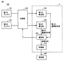
- FIG. 4 is a block diagram showing a functional configuration of smartphone 100 according to the first embodiment.
- the smartphone 100 includes a CPU 2, a first antenna 122, a second antenna 124, a switching unit 230, and a notification unit 280.
- the CPU 2 includes a first calculation unit 240, a second calculation unit 250, a selection unit 260, and a counting unit 270.
- the first calculation unit 240 calculates a first communication success rate when wireless communication is performed with a communication device via the first antenna 122.
- the first communication success rate is, for example, load modulation level, carrier detection sensitivity, BER (Bit Error Rate) value, PER (Packet Error Rate) value, C / N (Carrier / Noise) value, RSSI (Received Signal Strength Indicator) ) At least one of the values etc. can be used.
- the first calculation unit 240 calculates the first communication success rate at regular intervals until the first communication success rate exceeds the first predetermined value.
- the first calculation unit 240 outputs the first communication success rate to the selection unit 260.
- the second calculation unit 250 calculates a second communication success rate when wireless communication is performed with the communication device via the second antenna 124.
- the second communication success rate for example, at least one of a load modulation level, a carrier detection sensitivity, a BER value, a PER value, a C / N value, an RSSI value, and the like can be used.
- the second calculation unit 250 calculates the second communication success rate at regular intervals until the second communication success rate exceeds the second predetermined value.
- the second calculation unit 250 outputs the second communication success rate to the selection unit 260. Note that the first predetermined value and the second predetermined value may be the same value.
- the selection unit 260 selects the first antenna 122 when the first communication success rate is larger than the first predetermined value. In addition, the selection unit 260, when the first communication success rate is smaller than the first predetermined value and the second communication success rate is larger than the second predetermined value, The second antenna 124 is selected. The switching unit 230 electrically connects the antenna selected by the selection unit 260 to the CPU 2.
- the selection unit 260 performs communication when the first communication success rate is smaller than the first predetermined value and the second communication success rate is smaller than the second predetermined value.
- the failure is output to the counting unit 270.
- the counting unit 270 has at least the number of times that the first communication success rate has not exceeded the first predetermined value and the number of times that the second communication success rate has not exceeded the second predetermined value.
- the number of communication failures including one is counted.
- the number of communication failures is the number of times the first communication success rate has not exceeded the first predetermined value and the second communication success rate has not exceeded the second predetermined value. Is the sum of The counting unit 270 causes the notification unit 280 to notify a communication error when the number of communication failures exceeds a predetermined number.
- the notification unit 280 notifies a communication error.
- the notification unit 280 notifies the communication error using voice, music, electronic sound, or the like as the speaker 8.
- reporting part 280 may display a communication error with a character or an image as the monitor 110. FIG.
- FIG. 5 is a circuit diagram of the IC chip 120.
- the IC chip 120 includes a first antenna 122, a second antenna 124, a switching unit 230, a matching circuit 330, and an IC 350.
- the first antenna 122 is connected to the switching unit 230 by a wiring 360.
- the second antenna 124 is connected to the switching unit 230 by a wiring 361.
- the switching unit 230, the matching circuit 330, and the IC 350 are connected by a wiring 363 and a wiring 364 through a node 341.
- the first antenna 122, the second antenna 124, the matching circuit 330, and the IC 350 are connected in parallel by a wiring 362 through a node 342 and a node 343.
- the switching unit 230 electrically connects the antenna selected by the selection unit 260 from the first antenna 122 and the second antenna 124 to the CPU 2.
- the first antenna 122 includes a coil 305 and a capacitor 306.
- the coil 305 and the capacitor 306 are connected in parallel between the node 301 and the node 302.
- the resonance frequency of the first antenna 122 is determined by the inductance of the coil 305 and the capacitance of the capacitor 306.
- the second antenna 124 includes a coil 315 and a capacitor 316. Coil 315 and capacitor 316 are connected in parallel between node 310 and node 311.
- the resonance frequency of the second antenna 124 is determined by the inductance of the coil 315 and the capacitance of the capacitor 316.
- the resonance frequency of the first antenna 122 and the resonance frequency of the second antenna 124 are the same.
- the matching circuit 330 matches the impedance of the IC 350 with the impedance of the first antenna 122 or the second antenna 124.
- the IC 350 includes a CPU (not shown), a ROM (not shown), a RAM (not shown), other memory (not shown), and the like.
- the smartphone 100 may be configured such that a CPU included in the IC 350 performs part or all of the functions of the smartphone 100.
- Personal information (ID, account information, etc.) is stored in a memory (not shown) included in the IC 350.
- the IC 350 reads personal information stored in the memory.
- the smartphone 100 performs a payment process based on the read personal information.
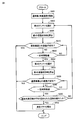
- FIG. 6 is a flowchart representing a part of the process executed by smartphone 100 according to the first embodiment.
- the processing in FIG. 6 is realized by the CPU 2 executing a program. In other aspects, some or all of the processing may be performed by circuit elements or other hardware.
- step S601 the CPU 2 starts wireless communication with the communication device.
- step S602 the CPU 2 selects the first antenna 122, and the switching unit 230 electrically connects the first antenna 122 to the CPU 2.
- step S ⁇ b> 603 the CPU 2 calculates a first communication success rate as the first calculation unit 240.
- step S610 the CPU 2 determines whether or not communication with the communication device has succeeded via the first antenna 122. Typically, the CPU 2 determines, as the selection unit 260, that the communication with the communication device has been successful when the first communication success rate exceeds the first predetermined value. If communication with the communication device is successful (YES in step S610), CPU 2 ends the process of this flow. If communication with the communication device has failed (NO in step S610), CPU 2 switches control to step S620.
- step S620 the CPU 2 measures time using the timer 5 to determine whether or not a certain time has elapsed since the start of communication.
- CPU 2 determines that the predetermined time has elapsed (YES in step S620)
- CPU 2 switches control to step S622.
- CPU 2 determines that the predetermined time has not elapsed (NO in step S620)
- CPU 2 switches control to step S610.
- step S622 the CPU 2 selects the second antenna 124, and the switching unit 230 electrically connects the second antenna 124 to the CPU 2.
- step S623 the CPU 2 calculates a second communication success rate as the first calculation unit 240.
- step S630 the CPU 2 determines whether or not the communication with the communication device is successful via the second antenna 124. Typically, the CPU 2 determines, as the selection unit 260, that the communication with the communication device is successful when the second communication success rate exceeds the second predetermined value. If communication with the communication device is successful (YES in step S630), CPU 2 ends the process of this flow. If communication with the communication device has failed (NO in step S630), CPU 2 switches control to step S640.
- step S640 the CPU 2 measures time by using the timer 5 to determine whether or not a certain time has elapsed since the start of communication.
- CPU 2 determines that the predetermined time has elapsed (YES in step S640)
- CPU 2 switches control to step S650.
- CPU 2 determines that the predetermined time has not elapsed (NO in step S640)
- CPU 2 switches control to step S630.
- step S650 the CPU 2 determines whether or not communication with the communication device has failed. Typically, when the number of communication failures counted by the counting unit 270 exceeds a predetermined number, the CPU 2 determines that communication with the communication device has failed. CPU2 switches control to step S652 when the number of communication failures exceeds a predetermined number of times (YES in step S650). If the number of communication failures does not exceed the predetermined number (NO in step S650), CPU 2 switches control to step S602. In step S ⁇ b> 652, the CPU 2 notifies the communication error as the notification unit 280. Thereafter, the CPU 2 ends the process of this flow.
- wireless communication can be performed with communication devices of various sizes by including a plurality of antennas having different sizes. Further, the communication success rate is improved by selecting an antenna having a communication success rate exceeding a predetermined value from a plurality of antennas. Thereby, power consumption caused by communication failure can be reduced. Furthermore, the plurality of antennas can be reduced in thickness by being arranged on the same plane.
- Smartphone 100A according to the second embodiment is different from smartphone 100 according to the first embodiment in the arrangement of antennas. Since it is the same as that of the smart phone 100 according to 1st Embodiment about another point, description is not repeated.
- FIG. 7 is a diagram for illustrating an outline of the IC chip 120A provided in the smartphone 100A according to the second embodiment.
- the IC chip 120A includes a first antenna 122A, a second antenna 124A, and a third antenna 126A.
- the sizes of the first antenna 122A to the third antenna 126A are different from each other, and the antennas are arranged on the same plane.
- the number of antennas shown in FIG. 7 is three, the number is not limited to three.
- the number of antennas arranged on the IC chip 120A may be two or more.
- the smartphone 100A calculates a communication success rate when wireless communication is performed with a communication device via each of the first antenna 122A to the third antenna 126A.
- the selection unit 260 selects the antenna with the highest communication success rate from the first antenna 122A to the third antenna 126A.
- wireless communication with a communication device is performed by selecting an antenna from among a plurality of adjacent antennas. Communication can be performed.
- Smartphone 100B according to the third embodiment is different from smartphone 100 according to the first embodiment in that IC chip 120B is provided instead of IC chip 120.
- the smartphone 100B is partially different from the smartphone 100 in the functional configuration. Since it is the same as that of the smart phone 100 according to 1st Embodiment about another point, description is not repeated.
- FIG. 8 is a diagram showing a circuit diagram of the IC chip 120B.
- the IC chip 120B differs from the IC chip 120 in that it further includes a node 801, a node 802, and a variable capacitor 810. Since other points are the same as those of the components included in the IC chip 120, description thereof will not be repeated.
- the IC chip 120B includes a variable capacitor 810 between the node 801 and the node 802.
- the smartphone 100 ⁇ / b> B determines the capacitance that improves the communication success rate by changing the capacitance of the variable capacitor 810.
- the smartphone 100B varies the capacitance of the variable capacitor 810 within a predetermined range.
- the resonance frequency (impedance) of the antenna varies, so that the voltage applied to the antenna and the IC 350 varies.
- the communication success rate with the communication device also changes.
- the smartphone 100B determines the capacitance that maximizes the communication success rate as the capacitance of the variable capacitor 810.
- the smartphone 100 ⁇ / b> B may determine the capacitance that maximizes the voltage applied to the antenna and the IC 350 as the capacitance of the variable capacitor 810.
- FIG. 9 is a block diagram showing a functional configuration of smartphone 100B according to the third embodiment.
- the smartphone 100 ⁇ / b> B is different from the smartphone 100 in that the smartphone 100 ⁇ / b> B further includes a variable capacitor 810, a variation unit 910, a third calculation unit 920, and a determination unit 930. Since other functional configurations are the same, description thereof will not be repeated.
- the variation unit 910 varies the capacitance of the variable capacitor 810 within a predetermined range. Typically, the variation unit 910 varies the capacitance based on the selection of the antenna by the selection unit 260.
- the third calculation unit 920 calculates a communication success rate when communication is performed with a communication device by changing the capacitance of the variable capacitor 810. Typically, the third calculation unit 920 calculates a plurality of communication success rates when communicating with the communication device via the antenna selected by the selection unit 260. The third calculation unit 920 outputs the calculated communication success rate to the determination unit 930.
- the determining unit 930 determines, as the electrostatic capacity of the variable capacitor 810, the electrostatic capacity that maximizes the communication success rate among the plurality of communication success rates. Note that the capacitance when the communication success rate exceeds a predetermined value may be determined as the capacitance of the variable capacitor 810.
- the communication performance can be improved by determining the capacitance of the variable capacitor so that the communication success rate is maximized. Further, by improving the communication performance, it is possible to reduce power consumption caused by communication failure.
- Smart phone 100 ⁇ / b> C according to the present embodiment is different from smartphone 100 according to the first embodiment in that the antenna having the higher communication success rate is selected from first antenna 122 and second antenna 124. Since it is the same as that of the smart phone 100 according to 1st Embodiment about another point, description is not repeated.
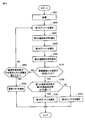
- FIG. 10 is a flowchart representing a part of the process executed by smartphone 100C according to the fourth embodiment.
- the processing in FIG. 10 is realized by the CPU 2 executing a program. In other aspects, some or all of the processing may be performed by circuit elements or other hardware. Steps S601 to S650 are similar to those of smartphone 100 according to the first embodiment, and therefore description thereof will not be repeated.
- step S710 the CPU 2 determines whether the wireless communication with the communication device is successful. Typically, the CPU 2 determines that when the first communication success rate exceeds the first predetermined value or when the second communication success rate exceeds the second predetermined value, Judge that communication was successful. When CPU 2 determines that wireless communication with the communication device has been successful (YES in step S710), CPU 2 switches control to step S720. When CPU 2 determines that wireless communication with the communication device has failed (NO in step S710), CPU 2 switches control to step S650.
- step S720 the CPU 2 determines whether or not the first communication success rate is higher than the second communication success rate.
- CPU 2 determines that the first communication success rate is higher than the second communication success rate (YES in step S720)
- CPU 2 switches control to step S721.
- CPU 2 determines that the first communication success rate is not higher than the second communication success rate (NO in step S720)
- CPU 2 switches control to step S722.
- step S721 the CPU 2 selects the first antenna 122, and the switching unit 230 electrically connects the first antenna 122 to the CPU 2.
- step S722 the CPU 2 selects the second antenna 124, and the switching unit 230 electrically connects the second antenna 124 to the CPU 2.
- the smartphone 100C selects an antenna having a better communication success rate from the plurality of antennas. Thereby, the smartphone 100 ⁇ / b> C can improve the communication success rate.
- the antenna provided in the smartphone may be printed on a housing.
- the first antenna is a large antenna and the second antenna is a small antenna.
- the first antenna may be a small antenna and the second antenna may be a large antenna.
- the antenna is mounted on the IC chips 120A, 120B, and 120C.
- the antenna is not necessarily mounted on the IC chips 120A, 120B, and 120C. Absent.
- the antenna may be mounted on any one of the smartphones 100A, 120B, and 120C.
Landscapes
- Engineering & Computer Science (AREA)
- Computer Networks & Wireless Communication (AREA)
- Telephone Function (AREA)
- Variable-Direction Aerials And Aerial Arrays (AREA)
- Near-Field Transmission Systems (AREA)
- Mobile Radio Communication Systems (AREA)
- Radio Transmission System (AREA)
Abstract
携帯端末装置を薄型化しつつ通信性能を改善するための携帯端末装置を提供する。 携帯端末装置は、通信機器と無線通信を行なうための第1のアンテナ(122)と、通信機器と無線通信を行なうための第2のアンテナ(124)とを備える。第1のアンテナ(122)および第2のアンテナ(124)は、互いに大きさが異なり、同一平面上に配置されている。携帯端末装置は、さらに、第1のアンテナ(122)を介して通信機器と無線通信を行なった場合の第1の通信成功率が第1の予め定められた値よりも大きい場合には、第1のアンテナ(122)を選択し、第1の通信成功率が第1の予め定められた値よりも小さく、かつ、第2のアンテナ(124)を介して通信機器と無線通信を行なった場合の第2の通信成功率が第2の予め定められた値よりも大きい場合には、第2のアンテナ(124)を選択するための選択部(260)を備える。
Description
本開示は、携帯端末装置の制御に関し、特に、通信機器と無線通信を行なう携帯端末装置の制御に関する。
近年、IC(Integrated Circuit)チップが組み込まれた非接触型ICカードや、非接触型ICタグ等の通信機器が普及している。このような通信機器の普及に伴い、ICチップが組み込まれた通信機器と無線通信を行なうための技術が開発されている。
たとえば、特開2011-165151号公報(特許文献1)は、「非接触ICカード機能の通信不能領域が発生しにくく、かつ高密度実装が可能な無線通信装置」を開示している([要約]参照)。当該無線通信装置は、異なる領域内に配置された第1のループアンテナと第2のループアンテナとを有し、受信電圧が所定の閾値以下のときには第1のループアンテナを選択し、受信電圧が所定の閾値よりも大きいときには第2のループアンテナを選択する。
ところで、近年、携帯端末装置の薄型化が進んでいる。しかしながら、特許文献1に開示されている無線通信装置は、第1のループアンテナおよび第2のループアンテナがそれぞれ異なる領域に配置されているため、携帯端末装置の薄型化には不向きである。また、RFID(Radio Frequency IDentification)のリーダライタ機能を搭載する携帯端末装置のアンテナの大きさ(または位置)と、RFIDカードやタグカード等のアンテナの大きさ(または位置)との違いにより最も同調するポイント(カプリング領域)が異なるため、通信が成功しにくい場合がある。このため、携帯端末装置を薄型化しつつ通信性能を改善するための技術が必要とされている。
この開示は上述のような問題点を解決するためになされたものであって、ある局面における目的は、携帯端末装置を薄型化しつつ通信性能を改善するための携帯端末装置を提供することである。
一実施の形態に従うと、携帯端末装置は、通信機器と無線通信を行なうための第1のアンテナと、通信機器と無線通信を行なうための第2のアンテナとを備える。第1のアンテナおよび第2のアンテナは、互いに大きさが異なり、同一平面上に配置されている。携帯端末装置は、さらに、第1のアンテナを介して通信機器と無線通信を行なった場合の第1の通信成功率が第1の予め定められた値よりも大きい場合には、第1のアンテナを選択し、第1の通信成功率が第1の予め定められた値よりも小さく、かつ、第2のアンテナを介して通信機器と無線通信を行なった場合の第2の通信成功率が第2の予め定められた値よりも大きい場合には、第2のアンテナを選択するための選択部を備える。
ある局面において、同一平面上配置された複数のアンテナのうちから、通信成功率に基づいてアンテナを選択することが可能な携帯端末装置を提供することができる。
この発明の上記および他の目的、特徴、局面および利点は、添付の図面と関連して理解されるこの発明に関する次の詳細な説明から明らかとなるであろう。
以下、図面を参照しつつ、本実施の形態について説明する。以下の説明では、同一の部品および構成要素には同一の符号を付してある。それらの名称および機能も同じである。したがって、これらについての詳細な説明は繰り返さない。
なお、以下では、携帯端末装置の一例であるスマートフォン100の詳細について説明するが、携帯端末装置はスマートフォンに限定されない。たとえば、携帯端末装置は、タブレット端末、デジタルカメラ、その他通信機器と無線通信できる携帯機器等も含む。また、以下で説明する第1~5の実施の形態において示す特徴的な構成は、本開示の趣旨を逸脱しない範囲で当然に相互に組み合わせが可能である。
[第1の実施の形態]
<概要>
図1および図2を参照して、第1の実施の形態に従うスマートフォン100の概要について説明する。図1は、第1の実施の形態に従うスマートフォン100が他の通信機器と無線通信している様子を示す図である。図2は、第1の実施の形態に従うスマートフォン100に備えられるICチップ120の概要を示すための図である。
<概要>
図1および図2を参照して、第1の実施の形態に従うスマートフォン100の概要について説明する。図1は、第1の実施の形態に従うスマートフォン100が他の通信機器と無線通信している様子を示す図である。図2は、第1の実施の形態に従うスマートフォン100に備えられるICチップ120の概要を示すための図である。
図1を参照して、スマートフォン100は、モニタ110とICチップ120とを有する。典型的には、ICチップ120は、モニタ110と反対の面に配置される。スマートフォン100は、通信機器と無線通信を行なう。たとえば、当該通信機器は、ICカード、ICタグ、自動取引装置、および、その他ICチップを有する通信端末を含む。
たとえば、図1に示されるように、スマートフォン100は、ICカード150または自動取引装置170と無線通信を行なう。典型的には、スマートフォン100は、ICカード150または自動取引装置170と近距離無線通信(NFC(Near Field Communication))を行う。近距離無線通信は、たとえば、数センチ~約1メートル程度の短距離で行う通信である。
スマートフォン100は、R/Wモードとカードモードとの2つの動作モードを有する。以下、R/Wモードおよびカードモードについて説明する。
(R/Wモード)
スマートフォン100は、動作モードがR/Wモードである場合、たとえば、自動取引装置として機能し、ICカード150と無線通信を行なう。ICカード150は、たとえば、クレジットカード、電車等の乗車券、またはその他ICチップを有するカードである。
スマートフォン100は、動作モードがR/Wモードである場合、たとえば、自動取引装置として機能し、ICカード150と無線通信を行なう。ICカード150は、たとえば、クレジットカード、電車等の乗車券、またはその他ICチップを有するカードである。
より具体的には、スマートフォン100は決済の金額の入力を受け付ける。ユーザがスマートフォン100をICカード150に近付けると、スマートフォン100とICカード150とが無線通信を開始する。スマートフォン100は、ICカード150からユーザの個人情報(たとえば、ユーザのID(Identification)および口座番号等)等を読み取る。スマートフォン100は、当該個人情報を基にネットワークに接続されている決済処理サーバ(図示しない)と通信を行なう。決済処理サーバは、スマートフォン100から受信したデータを用いて決済処理を行なう。
また、スマートフォン100は、商品管理端末として機能してもよい。この場合、スマートフォン100は、商品に付されたICタグと無線通信することで商品の情報(商品名、値段等)を読み取る。また、スマートフォン100は、ICタグに商品の情報を書込むこともできる。
(カードモード)
スマートフォン100は、動作モードがカードモードである場合、たとえば、おサイフケイタイ(登録商標)として機能する。この場合、ユーザがスマートフォン100を自動取引装置170に置くことにより自動的に決済を行う。より具体的には、自動取引装置170は、当該自動取引装置170に接続された制御装置(図示しない)から決済の金額が入力される。自動取引装置170は、決済の指示を受け付ける。ユーザが、スマートフォン100を自動取引装置170に置くと、スマートフォン100と自動取引装置170とが無線通信を開始する。自動取引装置170は、スマートフォン100からユーザの個人情報(たとえば、ユーザのIDおよび口座番号等)を読み取る。自動取引装置170は、当該個人情報を基にネットワークに接続されている決済処理サーバ(図示しない)と通信を行い、決済処理を行なう。
スマートフォン100は、動作モードがカードモードである場合、たとえば、おサイフケイタイ(登録商標)として機能する。この場合、ユーザがスマートフォン100を自動取引装置170に置くことにより自動的に決済を行う。より具体的には、自動取引装置170は、当該自動取引装置170に接続された制御装置(図示しない)から決済の金額が入力される。自動取引装置170は、決済の指示を受け付ける。ユーザが、スマートフォン100を自動取引装置170に置くと、スマートフォン100と自動取引装置170とが無線通信を開始する。自動取引装置170は、スマートフォン100からユーザの個人情報(たとえば、ユーザのIDおよび口座番号等)を読み取る。自動取引装置170は、当該個人情報を基にネットワークに接続されている決済処理サーバ(図示しない)と通信を行い、決済処理を行なう。
(アンテナ)
図2を参照して、スマートフォン100に搭載されるアンテナについて説明する。なお、以下では、アンテナがICチップ120に搭載されている例を挙げて説明を行なうが、アンテナは必ずしもICチップ120に搭載される必要はない。アンテナは、スマートフォン100のいずれかの部品に搭載されてもよい。
図2を参照して、スマートフォン100に搭載されるアンテナについて説明する。なお、以下では、アンテナがICチップ120に搭載されている例を挙げて説明を行なうが、アンテナは必ずしもICチップ120に搭載される必要はない。アンテナは、スマートフォン100のいずれかの部品に搭載されてもよい。
スマートフォン100がICカード150や自動取引装置170等の通信機器と無線通信を行なう場合、スマートフォン100に搭載されるアンテナの大きさ(または位置)と、当該通信機器に搭載されるアンテナの大きさ(または位置)との違いにより、スマートフォン100および当該通信機器が最も同調するポイント(カップリング領域)が異なる。これにより、スマートフォン100と当該通信機器との通信性能が変化する。このため、当該通信機器に搭載されるアンテナの大きさや位置に従って、スマートフォン100と当該通信機器とを同調させることが好ましい。
スマートフォン100に備えられるICチップ120は、第1のアンテナ122と、第2のアンテナ124とを備える。第1のアンテナ122と、第2のアンテナ124とは、互いに大きさが異なり、ICチップ120の同一平面上に配置される。典型的には、第1のアンテナ122は、閉じられた形状である。第2のアンテナ124は、第1のアンテナ122の内側に配置される。なお、アンテナの数は、図2において示されるように2つに限定されず、2つ以上であればよい。
スマートフォン100は、第1のアンテナ122および第2のアンテナ124を介して通信機器と無線通信を行ない、第1のアンテナ122および第2のアンテナ124のうちから通信成功率が高い方のアンテナを選択する。このように、スマートフォン100は、同一平面上にある、サイズの異なる第1のアンテナ122と第2のアンテナ124とのうちから通信しやすいアンテナを選択し、スマートフォン100および通信機器が最も同調するポイント(カップリング領域)を適切に選択することができる。これにより、スマートフォン100を様々な大きさの通信機器と無線通信させることができる。また、複数のアンテナが同一平面上に配置されることによりスマートフォン100を薄型化することができる。
<ハードウェア構成>
図3を参照して、第1の実施の形態に従うスマートフォン100の各構成について説明する。図3は、本実施の形態に従うスマートフォン100のハードウェア構成を示すブロック図である。
図3を参照して、第1の実施の形態に従うスマートフォン100の各構成について説明する。図3は、本実施の形態に従うスマートフォン100のハードウェア構成を示すブロック図である。
スマートフォン100は、ROM(Read Only Memory)1と、CPU(Central Processing Unit)2と、RAM(Random Access Memory)3と、タイマ5と、メモリカードI/F(Interface)6と、ネットワークI/F(Interface)7と、スピーカ8と、補助記憶装置20と、モニタ110と、ICチップ120とを備える。
ROM1は、オペレーティングシステム(OS:Operating System)や、スマートフォン100の起動時に実行されるプログラム等を格納する。
CPU2は、ROM1や補助記憶装置20等に格納された、オペレーティングシステムやスマートフォン100の制御プログラム等の各種プログラムを実行することで、スマートフォン100の動作を制御する。
RAM3は、ワーキングメモリとして機能し、プログラムの実行に必要な各種データを一時的に格納する。
ICチップ120は、第1のアンテナ122および第2のアンテナ124に電気的に接続される。スマートフォン100は、第1のアンテナ122および第2のアンテナ124のいずれか一方を介して通信機器と無線通信を行なう。たとえば、スマートフォン100は、近距離無線通信(NFC)により無線通信を行う。無線通信の態様は、近距離無線通信に限られない。
第1のアンテナ122および第2のアンテナ124は互いに大きさが異なり、同一平面上に配置される。典型的には、第1のアンテナ122は、閉じられた形状であり、第2のアンテナ124は、第1のアンテナ122の内側に配置される。より具体的には、第1のアンテナ122および第2のアンテナ124は矩形である。なお、第1のアンテナ122および第2のアンテナ124は、円形若しくは楕円形等の環状、三角形若しくは四角形等の多角形形状、またはその他の形状であってもよい。
モニタ110は、タッチセンサ(図示しない)と組み合わされることでタッチパネルとして機能する。たとえば、当該タッチパネルは無線通信の開始の指示の入力を受け付ける。当該タッチパネルがその指示の入力を受け付けると、スマートフォン100は通信機器と無線通信を開始する。また、モニタ110は、ICカードやICタグ等から読込んだ残高情報、取引履歴、商品情報等を表示する。
タイマ5は、スマートフォン100が通信機器と通信を行なっている時間または通信が開始されてから通信が確立するまでの時間を計測する。スマートフォン100は、当該通信が開始されてから通信が確立するまでの計測された時間が予め定められた時間を経過した場合に通信エラーと判断する。
メモリカードI/F6は、SD(Secure Digital)カードやCF(Compact Flash(登録商標))カード等のメモリカード30との間で、データの読み書きを行なう。
ネットワークI/F7は、アンテナ71を介して他の通信機器とメールデータ等の送受信を行なう。たとえば、他の通信機器は、スマートフォン、パソコン、サーバ装置、その他通信機能を有する電子機器である。
スピーカ8は、通信機器との通信の開始や終了等を音で出力する。また、スピーカ8は、通信機器との通信の成功や失敗等を音で出力する。当該音は、たとえば、音声、音楽、電子音を含む。
<機能構成>
図4を参照して、スマートフォン100の機能構成の一例について説明する。図4は、第1の実施の形態に従うスマートフォン100の機能構成を示すブロック図である。
図4を参照して、スマートフォン100の機能構成の一例について説明する。図4は、第1の実施の形態に従うスマートフォン100の機能構成を示すブロック図である。
スマートフォン100は、CPU2と、第1のアンテナ122と、第2のアンテナ124と、切換部230と、報知部280とを備える。CPU2は、第1の算出部240と、第2の算出部250と、選択部260と、計数部270とを含む。
第1の算出部240は、第1のアンテナ122を介して通信機器と無線通信を行なった場合の第1の通信成功率を算出する。第1の通信成功率は、たとえば、負荷変調レベル、搬送波検出感度、BER(Bit Error Rate)値、PER(Packet Error Rate)値、C/N(Carrier/Noise)値、RSSI(Received Signal Strength Indicator)値等のうちの少なくとも1つを用いることが可能である。第1の算出部240は、第1の通信成功率が第1の予め定められた値を越えるまで一定時間毎に第1の通信成功率を算出する。第1の算出部240は、第1の通信成功率を選択部260に出力する。
第2の算出部250は、第2のアンテナ124を介して通信機器と無線通信を行なった場合の第2の通信成功率を算出する。第2の通信成功率は、たとえば、負荷変調レベル、搬送波検出感度、BER値、PER値、C/N値、RSSI値等のうちの少なくとも1つを用いることが可能である。第2の算出部250は、第2の通信成功率が第2の予め定められた値を越えるまで一定時間毎に第2の通信成功率を算出する。第2の算出部250は、第2の通信成功率を選択部260に出力する。なお、第1の予め定められた値および第2の予め定められた値は同じ値であってもよい。
選択部260は、第1の通信成功率が第1の予め定められた値よりも大きい場合には第1のアンテナ122を選択する。また、選択部260は、第1の通信成功率が第1の予め定められた値よりも小さく、かつ、第2の通信成功率が第2の予め定められた値よりも大きい場合には、第2のアンテナ124を選択する。切換部230は、選択部260により選択されたアンテナを電気的にCPU2に接続する。
また、選択部260は、第1の通信成功率が第1の予め定められた値よりも小さく、かつ、第2の通信成功率が第2の予め定められた値よりも小さい場合、通信に失敗したことを計数部270に出力する。
計数部270は、第1の通信成功率が第1の予め定められた値を越えなかった回数、および、第2の通信成功率が第2の予め定められた値を越えなかった回数の少なくとも一方を含んだ通信失敗回数を計数する。典型的には、通信失敗回数は、第1の通信成功率が第1の予め定められた値を越えなかった回数と、第2の通信成功率が第2の予め定められた値を越えなかった回数との和である。計数部270は、通信失敗回数が予め定められた回数を越えた場合に、報知部280に通信エラーを報知させる。
報知部280は通信エラーを報知する。報知部280は、たとえば、スピーカ8として音声、音楽、電子音等で通信エラーを報知する。また、報知部280は、モニタ110として、通信エラーを文字または画像で表示してもよい。
<回路構成>
図5を参照して、ICチップ120の主要な回路部品について説明する。図5は、ICチップ120の回路図である。
図5を参照して、ICチップ120の主要な回路部品について説明する。図5は、ICチップ120の回路図である。
ICチップ120は、第1のアンテナ122と、第2のアンテナ124と、切換部230と、整合回路330と、IC350とを含む。
第1のアンテナ122は、配線360により切換部230と接続される。第2のアンテナ124は、配線361により切換部230と接続される。切換部230と、整合回路330と、IC350とは、ノード341を介して配線363および配線364によって接続される。第1のアンテナ122と、第2のアンテナ124と、整合回路330と、IC350とは、ノード342およびノード343を介して配線362により並列に接続される。
切換部230は、第1のアンテナ122および第2のアンテナ124のうちから選択部260により選択されたアンテナをCPU2に電気的に接続する。
第1のアンテナ122は、コイル305およびコンデンサ306を含む。コイル305およびコンデンサ306は、ノード301とノード302との間で並列に接続される、第1のアンテナ122の共振周波数は、コイル305のインダクタンスとコンデンサ306の静電容量とによって決定される。
第2のアンテナ124は、コイル315およびコンデンサ316を含む。コイル315およびコンデンサ316は、ノード310とノード311との間で並列に接続される。第2のアンテナ124の共振周波数は、コイル315のインダクタンスと、コンデンサ316の静電容量とによって決定される。典型的には、第1のアンテナ122の共振周波数と、第2のアンテナ124の共振周波数とは同一である。
整合回路330は、IC350におけるインピーダンスと、第1のアンテナ122または第2のアンテナ124のインピーダンスとを整合する。
IC350は、CPU(図示しない)、および、ROM(図示しない)、RAM(図示しない)、その他のメモリ(図示しない)等を含む。スマートフォン100は、当該スマートフォン100が有する機能の一部または全部をIC350に含まれるCPUが行なうように構成されてもよい。
IC350に含まれるメモリ(図示しない)には、個人情報(ID、口座情報等)が格納される。スマートフォン100の動作モードがカードモードの場合に、IC350は、当該メモリに格納される個人情報の読み出しを行なう。スマートフォン100は、読み取った個人情報に基づいて決済処理等を行なう。
<フローチャート>
図6は、第1の実施の形態に従うスマートフォン100が実行する処理の一部を表わすフローチャートである。図6の処理は、CPU2がプログラムを実行することにより実現される。他の局面において、処理の一部又は全部が、回路素子その他のハードウェアによって実行されてもよい。
図6は、第1の実施の形態に従うスマートフォン100が実行する処理の一部を表わすフローチャートである。図6の処理は、CPU2がプログラムを実行することにより実現される。他の局面において、処理の一部又は全部が、回路素子その他のハードウェアによって実行されてもよい。
ステップS601において、CPU2は、通信機器との無線通信を開始する。ステップS602において、CPU2は第1のアンテナ122を選択し、切換部230は第1のアンテナ122をCPU2に電気的に接続する。ステップS603において、CPU2は、第1の算出部240として、第1の通信成功率を算出する。
ステップS610において、CPU2は、第1のアンテナ122を介して通信機器との通信が成功したか否かを判断する。典型的には、CPU2は、選択部260として、第1の通信成功率が第1の予め定められた値を超えた場合に、通信機器との通信が成功したと判断する。通信機器との通信が成功した場合(ステップS610においてYES)、CPU2は本フローの処理を終了する。通信機器との通信が失敗した場合(ステップS610においてNO)、CPU2は、制御をステップS620に切り換える。
ステップS620において、CPU2は、タイマ5を用いて時間を計測することにより通信を開始してから一定時間が経過したか否かを判断する。CPU2は、一定時間が経過したと判断した場合(ステップS620においてYES)、制御をステップS622に切り換える。CPU2は、一定時間が経過していないと判断した場合(ステップS620においてNO)、制御をステップS610に切り換える。
ステップS622において、CPU2は、第2のアンテナ124を選択し、切換部230は第2のアンテナ124をCPU2に電気的に接続する。ステップS623において、CPU2は、第1の算出部240として、第2の通信成功率を算出する。
ステップS630において、CPU2は、第2のアンテナ124を介して通信機器との通信が成功したか否かを判断する。典型的には、CPU2は、選択部260として、第2の通信成功率が第2の予め定められた値を超えた場合に、通信機器との通信が成功したと判断する。通信機器との通信が成功した場合(ステップS630においてYES)、CPU2は本フローの処理を終了する。通信機器との通信が失敗した場合(ステップS630においてNO)、CPU2は、制御をステップS640に切り換える。
ステップS640において、CPU2は、タイマ5を用いて時間を計測することにより通信を開始してから一定時間が経過したか否かを判断する。CPU2は、一定時間が経過したと判断した場合(ステップS640においてYES)、制御をステップS650に切り換える。CPU2は、一定時間が経過していないと判断した場合(ステップS640においてNO)、制御をステップS630に切り換える。
ステップS650において、CPU2は、通信機器との通信が失敗したか否かを判断する。典型的には、計数部270によって計数された通信失敗回数が予め定められた回数を越えた場合に、CPU2は、通信機器との通信が失敗したと判断する。CPU2は、通信失敗回数が予め定められた回数を越えた場合(ステップS650においてYES)、制御をステップS652に切り替える。通信失敗回数が予め定められた回数を越えていない場合(ステップS650においてNO)、CPU2は、制御をステップS602に切り換える。ステップS652において、CPU2は、報知部280として、通信エラーを報知する。その後、CPU2は、本フローの処理を終了する。
<利点>
以上のようにして、本実施の形態に従うスマートフォン100によれば、大きさの異なる複数のアンテナを備えることにより様々な大きさの通信機器と無線通信を行なうことができる。また、複数のアンテナのうちから通信成功率が予め定められた値を越えるアンテナを選択することにより通信成功率が改善される。これにより、通信の失敗により生じる電力の消費を削減することができる。さらに、複数のアンテナが同一平面上に配置されることにより薄型化することができる。
以上のようにして、本実施の形態に従うスマートフォン100によれば、大きさの異なる複数のアンテナを備えることにより様々な大きさの通信機器と無線通信を行なうことができる。また、複数のアンテナのうちから通信成功率が予め定められた値を越えるアンテナを選択することにより通信成功率が改善される。これにより、通信の失敗により生じる電力の消費を削減することができる。さらに、複数のアンテナが同一平面上に配置されることにより薄型化することができる。
[第2の実施の形態]
<概要>
以下、第2の実施の形態に従うスマートフォン100Aについて説明する。本実施の形態に従うスマートフォン100Aは、アンテナの配置が第1の実施の形態に従うスマートフォン100と異なる。その他の点については、第1の実施の形態に従うスマートフォン100と同様であるので説明を繰り返さない。
<概要>
以下、第2の実施の形態に従うスマートフォン100Aについて説明する。本実施の形態に従うスマートフォン100Aは、アンテナの配置が第1の実施の形態に従うスマートフォン100と異なる。その他の点については、第1の実施の形態に従うスマートフォン100と同様であるので説明を繰り返さない。
図7を参照して、ICチップ120A上のアンテナの配置について説明する。図7は、第2の実施の形態に従うスマートフォン100Aに備えられるICチップ120Aの概要を示すための図である。
ICチップ120Aは、第1のアンテナ122Aと、第2のアンテナ124Aと、第3のアンテナ126Aとを含む。第1のアンテナ122A~第3のアンテナ126Aの大きさは、互いに異なり、各アンテナは、同一平面上に配置される。なお、図7に示されるアンテナの数は3つであるが3つに限定されない。ICチップ120Aに配置されるアンテナの数は、2つ以上であればよい。
スマートフォン100Aは、第1のアンテナ122A~第3のアンテナ126Aの各々を介して通信機器と無線通信を行なった場合の通信成功率を算出する。選択部260は、第1のアンテナ122A~第3のアンテナ126Aのうちから、通信成功率が一番高くなるアンテナを選択する。
<利点>
以上のようにして、本実施の形態に従うスマートフォン100によれば、互いに隣合う複数のアンテナのうちからアンテナを選択して通信機器と無線通信を行なるため、様々な大きさの通信機器と無線通信を行なうことができる。
以上のようにして、本実施の形態に従うスマートフォン100によれば、互いに隣合う複数のアンテナのうちからアンテナを選択して通信機器と無線通信を行なるため、様々な大きさの通信機器と無線通信を行なうことができる。
[第3の実施の形態]
<概要>
以下、第3の実施の形態に従うスマートフォン100Bについて説明する。本実施の形態に従うスマートフォン100Bは、ICチップ120の代わりにICチップ120Bを有する点が第1の実施の形態に従うスマートフォン100と異なる。また、スマートフォン100Bは、スマートフォン100と機能構成において一部異なる。その他の点については、第1の実施の形態に従うスマートフォン100と同様であるので説明を繰り返さない。
<概要>
以下、第3の実施の形態に従うスマートフォン100Bについて説明する。本実施の形態に従うスマートフォン100Bは、ICチップ120の代わりにICチップ120Bを有する点が第1の実施の形態に従うスマートフォン100と異なる。また、スマートフォン100Bは、スマートフォン100と機能構成において一部異なる。その他の点については、第1の実施の形態に従うスマートフォン100と同様であるので説明を繰り返さない。
<回路構成>
図8を参照して、ICチップ120Bの回路構成について説明する。図8は、ICチップ120Bの回路図を示す図である。ICチップ120Bは、ノード801と、ノード802と、可変コンデンサ810とをさらに含む点がICチップ120と異なる。その他の点については、ICチップ120に含まれる各構成と同様であるので説明を繰り返さない。
図8を参照して、ICチップ120Bの回路構成について説明する。図8は、ICチップ120Bの回路図を示す図である。ICチップ120Bは、ノード801と、ノード802と、可変コンデンサ810とをさらに含む点がICチップ120と異なる。その他の点については、ICチップ120に含まれる各構成と同様であるので説明を繰り返さない。
ICチップ120Bは、ノード801とノード802との間に可変コンデンサ810を含む。スマートフォン100Bは、可変コンデンサ810の静電容量を変動させることによって、通信成功率が改善するような静電容量を決定する。
より具体的には、スマートフォン100Bは、可変コンデンサ810の静電容量を予め定められた範囲内で変動させる。可変コンデンサ810の静電容量が変動するとアンテナの共振周波数(インピーダンス)が変動するため、アンテナおよびIC350にかかる電圧が変化する。これにより、通信機器との通信成功率もまた変化する。
典型的には、スマートフォン100Bは、通信成功率が最大となる静電容量を可変コンデンサ810の静電容量として決定する。また、スマートフォン100Bは、アンテナおよびIC350にかかる電圧が最大になるような静電容量を可変コンデンサ810の静電容量として決定してもよい。
<機能構成>
図9は、第3の実施の形態に従うスマートフォン100Bの機能構成を示すブロック図である。図9を参照して、スマートフォン100Bの機能構成の一例について説明する。スマートフォン100Bは、可変コンデンサ810と、変動部910と、第3の算出部920と、決定部930とをさらに備える点がスマートフォン100と異なる。その他の機能構成については同様であるので説明を繰り返さない。
図9は、第3の実施の形態に従うスマートフォン100Bの機能構成を示すブロック図である。図9を参照して、スマートフォン100Bの機能構成の一例について説明する。スマートフォン100Bは、可変コンデンサ810と、変動部910と、第3の算出部920と、決定部930とをさらに備える点がスマートフォン100と異なる。その他の機能構成については同様であるので説明を繰り返さない。
変動部910は、可変コンデンサ810の静電容量を予め定められた範囲で変動させる。典型的には、変動部910は、選択部260によりアンテナが選択されたことに基づいて静電容量を変動させる。
第3の算出部920は、可変コンデンサ810の静電容量を変動させて通信機器と通信を行なった場合の通信成功率を算出する。典型的には、第3の算出部920は、選択部260により選択されたアンテナを介して通信機器と通信した場合の複数の通信成功率を算出する。第3の算出部920は、算出した通信成功率を決定部930に出力する。
決定部930は、複数の通信成功率のうちから通信成功率が最大になる静電容量を可変コンデンサ810の静電容量として決定する。なお、通信成功率が予め定められた値を越えた時の静電容量を可変コンデンサ810の静電容量として決定してもよい。
<利点>
以上のようにして、本実施の形態に従うスマートフォン100Bによれば、通信成功率が最大になるように可変コンデンサの静電容量が決定されることにより通信性能を改善できる。また、通信性能が改善されることにより、通信の失敗により生じる電力の消費を削減することができる。
以上のようにして、本実施の形態に従うスマートフォン100Bによれば、通信成功率が最大になるように可変コンデンサの静電容量が決定されることにより通信性能を改善できる。また、通信性能が改善されることにより、通信の失敗により生じる電力の消費を削減することができる。
[第4の実施の形態]
<概要>
以下、第4の実施の形態に従うスマートフォン100Cについて説明する。本実施の形態に従うスマートフォン100Cは、第1のアンテナ122および第2のアンテナ124のうちから、通信成功率が高い方のアンテナを選択する点が第1の実施の形態に従うスマートフォン100と異なる。その他の点については、第1の実施の形態に従うスマートフォン100と同様であるので説明を繰り返さない。
<概要>
以下、第4の実施の形態に従うスマートフォン100Cについて説明する。本実施の形態に従うスマートフォン100Cは、第1のアンテナ122および第2のアンテナ124のうちから、通信成功率が高い方のアンテナを選択する点が第1の実施の形態に従うスマートフォン100と異なる。その他の点については、第1の実施の形態に従うスマートフォン100と同様であるので説明を繰り返さない。
<フローチャート>
図10は、第4の実施の形態に従うスマートフォン100Cが実行する処理の一部を表わすフローチャートである。図10の処理は、CPU2がプログラムを実行することにより実現される。他の局面において、処理の一部又は全部が、回路素子その他のハードウェアによって実行されてもよい。なお、ステップS601~ステップS650においては、第1の実施の形態に従うスマートフォン100と同様であるので説明を繰り返さない。
図10は、第4の実施の形態に従うスマートフォン100Cが実行する処理の一部を表わすフローチャートである。図10の処理は、CPU2がプログラムを実行することにより実現される。他の局面において、処理の一部又は全部が、回路素子その他のハードウェアによって実行されてもよい。なお、ステップS601~ステップS650においては、第1の実施の形態に従うスマートフォン100と同様であるので説明を繰り返さない。
ステップS710において、CPU2は、通信機器との無線通信が成功した否かを判断する。典型的には、CPU2は、第1の通信成功率が第1の予め定められた値を超えたか、または、第2の通信成功率が第2の予め定められた値を超えた場合に、通信が成功したと判断する。CPU2は、通信機器との無線通信が成功したと判断した場合(ステップS710においてYES)、制御をステップS720に切り換える。CPU2は、通信機器との無線通信が失敗したと判断した場合(ステップS710においてNO)、制御をステップS650に切り換える。
ステップS720において、CPU2は、第1の通信成功率が第2の通信成功率よりも高いか否かを判断する。CPU2は、第1の通信成功率が第2の通信成功率よりも高いと判断した場合(ステップS720においてYES)、制御をステップS721に切り換える。CPU2は、第1の通信成功率が第2の通信成功率よりも高くないと判断した場合(ステップS720においてNO)、制御をステップS722に切り換える。
ステップS721において、CPU2は、第1のアンテナ122を選択し、切換部230は第1のアンテナ122をCPU2に電気的に接続する。ステップS722において、CPU2は、第2のアンテナ124を選択し、切換部230は第2のアンテナ124をCPU2に電気的に接続する。
<利点>
以上のようにして、スマートフォン100Cは、複数のアンテナのうちから通信成功率がより良くなるアンテナを選択する。これにより、スマートフォン100Cは、通信成功率を改善することが可能になる。
以上のようにして、スマートフォン100Cは、複数のアンテナのうちから通信成功率がより良くなるアンテナを選択する。これにより、スマートフォン100Cは、通信成功率を改善することが可能になる。
[第5の実施の形態]
他の局面において、スマートフォンに設けられるアンテナは、筺体に印刷されたものであってもよい。
他の局面において、スマートフォンに設けられるアンテナは、筺体に印刷されたものであってもよい。
また、上記では第1のアンテナを大きいアンテナ、第2のアンテナを小さいアンテナとして説明したが、第1のアンテナを小さいアンテナ、第2のアンテナを大きいアンテナとしてもよい。
また、第2~第5の実施の形態においても、アンテナがICチップ120A、120B、120Cに搭載されている例を挙げたが、アンテナは必ずしもICチップ120A、120B、120Cに搭載される必要はない。アンテナは、スマートフォン100A、120B、120Cのいずれかの部品にそれぞれ搭載されてもよい。
今回開示された実施の形態はすべての点で例示であって制限的なものではないと考えられるべきである。本発明の範囲は上記した説明ではなくて請求の範囲によって示され、請求の範囲と均等の意味および範囲内でのすべての変更が含まれることが意図される。
1 ROM、2 CPU、3 RAM、5 タイマ、6 メモリカードI/F、7 ネットワークI/F、8 スピーカ、20 補助記憶装置、30 メモリカード、71 アンテナ、100,100A,100B,100C スマートフォン、110 モニタ、120,120A,120B ICチップ、122,122A 第1のアンテナ、124,124A 第2のアンテナ、126A 第3のアンテナ、150 ICカード、170 自動取引装置、230 切換部、240 第1の算出部、250 第2の算出部、260 選択部、270 計数部、280 報知部、301,302,310,311,341,342,343,801,802 ノード、305,315 コイル、306,316 コンデンサ、330 整合回路、360,361,362,363,364 配線、810 可変コンデンサ、910 変動部、920 第3の算出部、930 決定部。
Claims (5)
- 通信機器と無線通信を行なうための第1のアンテナと、
前記通信機器と無線通信を行なうための第2のアンテナとを備え、
前記第1のアンテナおよび前記第2のアンテナは、互いに大きさが異なり、同一平面上に配置されており、さらに、
前記第1のアンテナを介して前記通信機器と無線通信を行なった場合の第1の通信成功率が第1の予め定められた値よりも大きい場合には、前記第1のアンテナを選択し、前記第1の通信成功率が前記第1の予め定められた値よりも小さく、かつ、前記第2のアンテナを介して前記通信機器と無線通信を行なった場合の第2の通信成功率が第2の予め定められた値よりも大きい場合には、前記第2のアンテナを選択するための選択部を備える、携帯端末装置。 - 通信機器と無線通信を行なうための第1のアンテナと、
前記通信機器と無線通信を行なうための第2のアンテナとを備え、
前記第1のアンテナおよび前記第2のアンテナは、互いに大きさが異なり、同一平面上に配置されており、さらに、
予め定められた時間内に前記第1のアンテナを介して前記通信機器と無線通信を行なった場合の第1の通信成功率と、予め定められた時間内に前記第2のアンテナを介して前記通信機器と無線通信を行なった場合の第2の通信成功率とのうちの通信成功率が高いアンテナを選択するための選択部とを備える、携帯端末装置。 - 前記第1のアンテナの共振周波数と、前記第2のアンテナの共振周波数とは同一である、請求項1または2に記載の携帯端末装置。
- 前記第1の通信成功率が第1の予め定められた値を越えるまで一定時間間隔で第1の通信成功率を算出するための第1の算出部と、
前記第2の通信成功率が第2の予め定められた値を越えるまで一定時間間隔で第2の通信成功率を算出するための第2の算出部と、
前記第1の通信成功率が前記第1の予め定められた値を越えなかった回数、および、前記第2の通信成功率が前記第2の予め定められた値を越えなかった回数の少なくとも一方を含んだ通信失敗回数を計数するための計数部と、
前記通信失敗回数が予め定められた回数を越えた場合に、通信エラーを報知するための報知部とをさらに備える、請求項1~3のいずれか1項に記載の携帯端末装置。 - 前記第1のアンテナおよび前記第2のアンテナに並列に接続される可変コンデンサと、
前記可変コンデンサの静電容量を変動するための変動部と、
前記変動部により前記静電容量を変動させて、前記通信機器と通信を行なった場合の複数の通信成功率を算出するための算出部と、
前記複数の通信成功率のうちから通信成功率が最大になる静電容量を前記可変コンデンサの静電容量として決定するための決定部とをさらに備える、請求項1~4のいずれか1項に記載の携帯端末装置。
Applications Claiming Priority (2)
| Application Number | Priority Date | Filing Date | Title |
|---|---|---|---|
| JP2013175526A JP2015046674A (ja) | 2013-08-27 | 2013-08-27 | 携帯端末装置 |
| JP2013-175526 | 2013-08-27 |
Publications (1)
| Publication Number | Publication Date |
|---|---|
| WO2015029784A1 true WO2015029784A1 (ja) | 2015-03-05 |
Family
ID=52586353
Family Applications (1)
| Application Number | Title | Priority Date | Filing Date |
|---|---|---|---|
| PCT/JP2014/071370 Ceased WO2015029784A1 (ja) | 2013-08-27 | 2014-08-13 | 携帯端末装置 |
Country Status (2)
| Country | Link |
|---|---|
| JP (1) | JP2015046674A (ja) |
| WO (1) | WO2015029784A1 (ja) |
Citations (5)
| Publication number | Priority date | Publication date | Assignee | Title |
|---|---|---|---|---|
| JP2006186865A (ja) * | 2004-12-28 | 2006-07-13 | Toshiba Corp | 電子機器および通信制御方法 |
| JP2007036303A (ja) * | 2005-06-23 | 2007-02-08 | Sony Corp | 受信端末装置 |
| JP2007281818A (ja) * | 2006-04-05 | 2007-10-25 | Sony Corp | 非接触icカード、アンテナ動作切換方法及び携帯端末 |
| JP2009543442A (ja) * | 2006-06-27 | 2009-12-03 | センサーマティック・エレクトロニクス・コーポレーション | 動的インピーダンス整合を有する共振回路同調システム |
| JP2010233048A (ja) * | 2009-03-27 | 2010-10-14 | Nec Corp | 無線通信装置及び無線通信方法 |
Family Cites Families (2)
| Publication number | Priority date | Publication date | Assignee | Title |
|---|---|---|---|---|
| JPH0983418A (ja) * | 1995-09-06 | 1997-03-28 | Kyocera Corp | アンテナ及び受信回路の異常検出方法 |
| JP3432768B2 (ja) * | 1999-04-15 | 2003-08-04 | 松下電器産業株式会社 | 携帯型通信端末用アンテナ |
-
2013
- 2013-08-27 JP JP2013175526A patent/JP2015046674A/ja active Pending
-
2014
- 2014-08-13 WO PCT/JP2014/071370 patent/WO2015029784A1/ja not_active Ceased
Patent Citations (5)
| Publication number | Priority date | Publication date | Assignee | Title |
|---|---|---|---|---|
| JP2006186865A (ja) * | 2004-12-28 | 2006-07-13 | Toshiba Corp | 電子機器および通信制御方法 |
| JP2007036303A (ja) * | 2005-06-23 | 2007-02-08 | Sony Corp | 受信端末装置 |
| JP2007281818A (ja) * | 2006-04-05 | 2007-10-25 | Sony Corp | 非接触icカード、アンテナ動作切換方法及び携帯端末 |
| JP2009543442A (ja) * | 2006-06-27 | 2009-12-03 | センサーマティック・エレクトロニクス・コーポレーション | 動的インピーダンス整合を有する共振回路同調システム |
| JP2010233048A (ja) * | 2009-03-27 | 2010-10-14 | Nec Corp | 無線通信装置及び無線通信方法 |
Also Published As
| Publication number | Publication date |
|---|---|
| JP2015046674A (ja) | 2015-03-12 |
Similar Documents
| Publication | Publication Date | Title |
|---|---|---|
| US9413430B2 (en) | Measurement and reporting of received signal strength in NFC enabled devices | |
| US10516208B2 (en) | Electronic device including shielding structure | |
| TWI504229B (zh) | 支援電子錢包功能之行動裝置 | |
| US8670712B2 (en) | Mobile terminal and method for providing enhanced contactless communication using contactless module | |
| EP2728510B1 (en) | NFC device and communication method | |
| US8282009B2 (en) | Mobile device and power management method | |
| CN100405396C (zh) | 具有智能卡中断功能的移动终端 | |
| US10944167B2 (en) | Electronic device that reduces antenna interference and enhances antenna performance | |
| US7458518B2 (en) | Loop antenna and electronic equipment including loop antenna | |
| WO2009058496A1 (en) | Detection apparatus and method for near field communication | |
| US20210314028A1 (en) | Communication device and operating method | |
| JP2011180698A (ja) | 携帯端末及びプログラム | |
| KR102452409B1 (ko) | 방사 부재를 포함하는 전자 장치 | |
| JPWO2016093057A1 (ja) | アンテナ及び通信装置 | |
| KR20200093009A (ko) | 전자 거래 방법 및 단말기 | |
| JP2013016076A (ja) | Icタグ及び電子機器 | |
| US9219519B2 (en) | Proximity wireless transmission/reception device | |
| JPWO2012053203A1 (ja) | 近距離無線通信装置 | |
| KR20150038848A (ko) | Nfc 장치의 수신기 및 이를 포함하는 nfc 장치 | |
| KR20210090050A (ko) | Rf 신호를 이용하여 무선 전력을 수신하는 전자 장치 및 그 제어 방법 | |
| US11309923B2 (en) | Method using signal component of multiplied frequency and electronic device therefor | |
| WO2015029784A1 (ja) | 携帯端末装置 | |
| CN102271013B (zh) | 支持电子钱包功能的移动装置 | |
| JP2003271914A (ja) | Icモジュール及びicモジュールを内蔵した非接触情報媒体 | |
| CN210609335U (zh) | 一种传输手机nfc信号的手机壳 |
Legal Events
| Date | Code | Title | Description |
|---|---|---|---|
| 121 | Ep: the epo has been informed by wipo that ep was designated in this application |
Ref document number: 14839635 Country of ref document: EP Kind code of ref document: A1 |
|
| NENP | Non-entry into the national phase |
Ref country code: DE |
|
| 122 | Ep: pct application non-entry in european phase |
Ref document number: 14839635 Country of ref document: EP Kind code of ref document: A1 |