WO2015029668A1 - プログラムおよび基地局装置 - Google Patents
プログラムおよび基地局装置 Download PDFInfo
- Publication number
- WO2015029668A1 WO2015029668A1 PCT/JP2014/069865 JP2014069865W WO2015029668A1 WO 2015029668 A1 WO2015029668 A1 WO 2015029668A1 JP 2014069865 W JP2014069865 W JP 2014069865W WO 2015029668 A1 WO2015029668 A1 WO 2015029668A1
- Authority
- WO
- WIPO (PCT)
- Prior art keywords
- mobile station
- timer
- station device
- station apparatus
- information indicating
- Prior art date
- Legal status (The legal status is an assumption and is not a legal conclusion. Google has not performed a legal analysis and makes no representation as to the accuracy of the status listed.)
- Ceased
Links
Images





Classifications
-
- H—ELECTRICITY
- H04—ELECTRIC COMMUNICATION TECHNIQUE
- H04W—WIRELESS COMMUNICATION NETWORKS
- H04W52/00—Power management, e.g. Transmission Power Control [TPC] or power classes
- H04W52/02—Power saving arrangements
- H04W52/0209—Power saving arrangements in terminal devices
- H04W52/0212—Power saving arrangements in terminal devices managed by the network, e.g. network or access point is leader and terminal is follower
- H04W52/0216—Power saving arrangements in terminal devices managed by the network, e.g. network or access point is leader and terminal is follower using a pre-established activity schedule, e.g. traffic indication frame
-
- H—ELECTRICITY
- H04—ELECTRIC COMMUNICATION TECHNIQUE
- H04W—WIRELESS COMMUNICATION NETWORKS
- H04W72/00—Local resource management
- H04W72/12—Wireless traffic scheduling
- H04W72/1263—Mapping of traffic onto schedule, e.g. scheduled allocation or multiplexing of flows
- H04W72/1273—Mapping of traffic onto schedule, e.g. scheduled allocation or multiplexing of flows of downlink data flows
-
- H—ELECTRICITY
- H04—ELECTRIC COMMUNICATION TECHNIQUE
- H04W—WIRELESS COMMUNICATION NETWORKS
- H04W72/00—Local resource management
- H04W72/20—Control channels or signalling for resource management
- H04W72/23—Control channels or signalling for resource management in the downlink direction of a wireless link, i.e. towards a terminal
-
- H—ELECTRICITY
- H04—ELECTRIC COMMUNICATION TECHNIQUE
- H04W—WIRELESS COMMUNICATION NETWORKS
- H04W76/00—Connection management
- H04W76/20—Manipulation of established connections
- H04W76/28—Discontinuous transmission [DTX]; Discontinuous reception [DRX]
-
- Y—GENERAL TAGGING OF NEW TECHNOLOGICAL DEVELOPMENTS; GENERAL TAGGING OF CROSS-SECTIONAL TECHNOLOGIES SPANNING OVER SEVERAL SECTIONS OF THE IPC; TECHNICAL SUBJECTS COVERED BY FORMER USPC CROSS-REFERENCE ART COLLECTIONS [XRACs] AND DIGESTS
- Y02—TECHNOLOGIES OR APPLICATIONS FOR MITIGATION OR ADAPTATION AGAINST CLIMATE CHANGE
- Y02D—CLIMATE CHANGE MITIGATION TECHNOLOGIES IN INFORMATION AND COMMUNICATION TECHNOLOGIES [ICT], I.E. INFORMATION AND COMMUNICATION TECHNOLOGIES AIMING AT THE REDUCTION OF THEIR OWN ENERGY USE
- Y02D30/00—Reducing energy consumption in communication networks
- Y02D30/70—Reducing energy consumption in communication networks in wireless communication networks
Definitions
- the present invention relates to a technique for reducing power consumption according to the usage status of a mobile station apparatus.
- RRC CONNECTED state states of mobile station devices.
- RRC IDLE state states of mobile station devices.
- RRC is an abbreviation of “Radio Resource Control”.
- the characteristics of the “RRC CONNECTED state” are as follows. -Wireless connection is established between the mobile station and the base station, and packet communication is possible. A radio resource for performing packet communication is allocated from the base station and notified by PDCCH. -Power consumption is high because PDCCH is continuously received in order to maintain wireless connection even during packet communication.
- the characteristics of the “RRC IDLE state” are as follows. -Wireless connection is not established between the mobile station and the base station, and packet communication is not possible. • When performing packet communication, it is necessary to establish a wireless connection and transition to the “RRC CONNECTED state”. -Intermittent reception of paging (incoming information) from the base station. ⁇ Power consumption is low.
- the mobile station When the mobile station performs packet communication, it establishes a wireless connection with the base station and performs in “RRC CONNECTED state”. The wireless connection is maintained for a certain period of time in the “RRC ⁇ ⁇ CONNECTED state” in preparation for the next packet communication after the end of the packet communication. If the no-communication state continues for a certain period of time, the wireless connection is disconnected and the state transitions to the “RRC ⁇ IDLE state” in order to improve the efficiency of radio resources and reduce the power consumption of the mobile station.
- the mobile station maintains the “RRC CONNECTED state” for a certain period during which the presence / absence of packet communication is measured.
- This “RRC CONNECTED state” is a state of high power consumption as described above, and maintaining the “RRC CONNECTED state” for a certain period of time may reduce the remaining battery level of the mobile station at an early stage.
- the possibility of continuous packet communication is low, and there is a high possibility that a certain period of time when power consumption is high is wasted.
- the present invention has been made in view of such circumstances, and a program capable of reducing power consumption of a mobile station according to a user's usage status without stopping packet communication required by the user, and An object is to provide a base station apparatus.
- the present invention has taken the following measures. That is, the program of the present invention is a program for a base station apparatus that performs radio communication with a mobile station apparatus, and includes information indicating a use status of the mobile station apparatus together with a request for establishing a wireless connection from the mobile station apparatus.
- the first timer is started at the time when processing for setting a relatively short time in the first timer and packet communication with the mobile station device are completed, and the first timer
- a computer transmits a control signal to the mobile station apparatus to disconnect the wireless connection with the mobile station apparatus, and causes the computer to execute a series of processes.
- the relatively long time is set in the first timer, while the information indicating the usage status indicates the non-use of the mobile station device.
- a relatively short time is set as the first timer, the first timer is started when the packet communication with the mobile station apparatus is completed, and the mobile station apparatus is activated when the first timer expires.
- the wireless connection is established in preparation for the next packet communication. Can be maintained.
- the information indicating the usage status indicates that the mobile station device is not used, the user does not use the mobile station device, and it is unlikely that packet communication will occur continuously. By shortening it, it becomes possible to suppress the power consumption of the mobile station apparatus.
- the program of the present invention is a program of a base station apparatus that performs radio communication with a mobile station apparatus, and information indicating a use status of the mobile station apparatus together with a request for establishing a wireless connection from the mobile station apparatus.
- a second timer is set that determines the start timing of C-DRX (CONNECTED Discontinuous Reception) for a relatively long time.
- C-DRX CONNECTED Discontinuous Reception
- a process of setting a relatively short time in the second timer and a time point when packet communication with the mobile station apparatus ends. And starting the second timer, and causing the computer to execute a series of processes of intermittently transmitting a control signal when the second timer expires And wherein the door.
- the second timer that determines the start timing of C-DRX (CONNECTED Discontinuous Reception) is set for a relatively long time. If the information indicating that the mobile station device is not used, a relatively short time is set in the second timer, and when the packet communication with the mobile station device is completed, the second timer is started, Since the control signal is intermittently transmitted when the second timer expires, if the information indicating the use status indicates the use of the mobile station device, the wireless connection can be maintained in preparation for the next packet communication. it can.
- the present invention it is possible to reduce the power consumption of the mobile station according to the usage status of the user without stopping the packet communication required by the user.
- 3 is a sequence chart showing operations of a mobile station and a base station according to the first embodiment.
- 6 is a sequence chart showing operations of a mobile station and a base station according to the second embodiment. It is a flowchart which shows operation
- this is a state of power consumption during packet communication of the mobile station when the user is not using it.
- this embodiment it is the state of the power consumption at the time of packet communication of the mobile station when the user is not using it.
- it is a figure which shows the state of the power consumption at the time of packet communication of the mobile station when the user is not using.
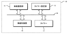
- FIG. 12 is a block diagram of the base station apparatus according to this embodiment.
- the base station device 10 acquires information indicating the usage status of the mobile station device together with a request for establishing a wireless connection from the mobile station device in the wireless communication unit 11.
- the timer setting unit 13 sets a relatively long time in the timer 17 when the information indicating the usage status acquired from the mobile station device indicates the usage of the mobile station device, while the information indicating the usage status is When indicating non-use of the mobile station apparatus, a relatively short time is set in the timer 17.
- the radio control unit 15 starts the timer 17 when transmission of the packet to the mobile station apparatus is completed, and transmits a control signal to the mobile station apparatus when the timer 17 expires to establish a wireless connection with the mobile station apparatus.
- Disconnect The timer 17 constitutes a first timer, a second timer, and a third timer. These components transmit and receive data to and from each other via the control bus 19.
- FIG. 13 is a block diagram of the mobile station apparatus according to this embodiment.
- the usage status determination unit 21 determines the usage status of the user's own device.
- the notification unit 23 notifies the base station apparatus of information indicating the usage status together with a request for establishing a wireless connection.
- the control unit 25 receives a control signal from the base station apparatus and transitions to an idle state. These components transmit and receive data to and from each other via the control bus 27.
- FIG. 1 is a sequence chart showing operations of the mobile station and the base station according to the first embodiment.
- the mobile station At the start of packet communication, the mobile station notifies the base station of the usage status of the user's mobile station.
- the base station determines the wireless connection maintenance time according to the usage status of the user.
- the UE mobile station determines the usage status of the user's mobile station, that is, “used” or “not used” (2). . Specifically, the lighting state of the display and the sound output state are confirmed.
- the mobile station transmits “RRC ⁇ Connection Request” to the base station (3).
- the mobile station usage state information (in use / not in use) is included in this message and notified to the base station.
- the base station notifies the mobile station of “RRC Connection Setup” and notifies the information necessary for establishing a wireless connection (4).
- the mobile station transmits “RRC Connection Complete” to the base station, establishes a wireless connection, and transitions to the “RRC CONNECTED state” (5).
- the mobile station performs packet communication (6). After the packet communication is completed, the base station starts “Release Timer” corresponding to the usage status of the mobile station (7).
- “Release Timer” is a timer for the time during which the base station maintains a wireless connection with the mobile station after the end of packet communication. Counting is started after packet communication is completed, and when the timer expires, “RRC Connection Release” is transmitted to the mobile station, and the wireless connection with the mobile station is disconnected.
- “Long Release timer” is started.
- “Short Release Timer” is set to a value shorter than “Long Release Release Timer”. For example, “Long Release Timer” is set to 10 seconds, and “Short Release Timer” is set to 2 seconds (or 0 seconds are acceptable).
- PDCCH Physical Dedicated Control ⁇ Channel
- PDCCH Physical Dedicated Control ⁇ Channel
- the user's usage status is determined based on the state of the display and the state of audio output.
- the present invention is not limited to this, and other than this.
- the use state of the user may be determined based on the detection state of the acceleration sensor, the vibration state of the vibration, or the like.
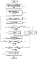
- FIG. 3 is a flowchart showing the operation of the base station according to this embodiment.
- “RRCRRConnection Request” including usage status information is received from the mobile station (step S1).
- “RRC Connection Setup” is transmitted to the mobile station, and the mobile station is transited to the “RRC CONNECTED state” (step S2).
- packet communication is performed with the mobile station (step S3).
- the use status of the mobile station by the user is determined, and “Release Timer” corresponding to the use status of the mobile station is set.
- Start step S5). That is, if the mobile station is “in use” in step S5, “Long Release Timer” for 300 seconds is started (step S7). On the other hand, if the mobile station is “not in use” in step S5, “Short Release Timer” for 5 seconds is started (step S6).
- the base station transmits the PDCCH to the mobile station to notify the radio resource allocation schedule information until “Release Timer” ends (step S8). During this time, it is determined whether or not a new packet communication is performed with the mobile station (step S9). If a new packet communication is performed with the mobile station, the process proceeds to step S2 to reset “ReleaseleTimer” again. Then, after the packet communication is completed, the Release Timer is started again. On the other hand, if there is no new packet communication in step S9, it is determined whether or not “Release Timer” has expired (step S10). If “Release Timer” has not expired, the process proceeds to step S8. When “Release Timer” expires, “RRC Connection Release” is transmitted to the mobile station, the mobile station is changed to the “RRC IDLE state” (step S11), and the process ends.
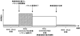
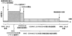
- FIG. 4 is a state of power consumption during packet communication of the mobile station when the user is not using it in the conventional technology.
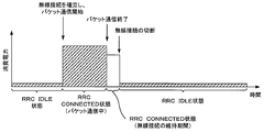
- FIG. 5 shows the state of power consumption during packet communication of the mobile station when the user is not using it in this embodiment.
- the wireless connection maintenance time after packet communication is shortened, and the power consumption of the mobile station can be reduced. That is, it is possible to reduce the power consumption of the mobile station according to the usage situation of the user with respect to the mobile station.
- C-DRX CONNECTED Discontinuous Reception, hereinafter referred to as “CDRX”
- CDRX C-DRX
- RRC CONNECTED state Normally, a mobile station in the “RRC CONNECTED state” continuously receives the PDCCH, but a mobile station in the “CDRX state” activates the reception circuit at regular intervals to receive the PDCCH. During this time, the receiving circuit is suspended. That is, CDRX is a PDCCH intermittent reception function. As a result, it is possible to keep power consumption low while being in a state where radio resources are allocated from the base station (a state where packet communication is possible).
- the mobile station notifies the base station of user usage information at the start of packet communication.
- the base station corresponding to the CDRX determines the timing for starting the CDRX to the mobile station according to the usage status of the user's mobile station.
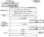
- FIG. 2 is a sequence chart showing operations of the mobile station and the base station according to the second embodiment.
- the mobile station determines the usage status of the user, that is, “in use” or “not in use” (2). Specifically, the lighting state of the mobile station display and the sound output state are confirmed.
- the mobile station transmits “RRC Connection Request” to the base station (3).
- information on the usage status of the user is included in this message and notified to the base station.
- the base station notifies “RRC Connection Setup” to the mobile station (4) and notifies information necessary for establishing a wireless connection.
- the mobile station transmits “RRC Connection Complete” to the base station (5), establishes a wireless connection, and transitions to the “RRC CONNECTED state”.
- the base station transmits “RRC Connection Reconfiguration” (6) to notify the mobile station of the CDRX parameters.
- the mobile station transmits “RRC Connection Reconfiguration Complete” (7) and returns a response. Then, the mobile station performs packet communication (8).
- the base station After the end of packet communication, the base station starts “CDRX Start Timer” corresponding to the usage status of the user (9). If the mobile station is “in use”, the base station starts “Long ⁇ CDRX Start Timer”. On the other hand, if the mobile station is “not used”, “Short CDRX Start Timer” is started.
- the base station continuously transmits the PDCCH to the mobile station until “CDRX Start Timer” expires (10). “CDRX Start Timer” expires (11), the base station intermittently transmits PDCCH to the mobile station (12), and the mobile station starts CDRX that intermittently receives PDCCH (13).
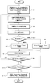
- FIG. 10 is a flowchart showing the operation of the base station according to this embodiment.
- the base station receives “RRC Connection Request” including information on the usage status of the user from the mobile station (step T1).
- “RRC Connection Setup” is transmitted to the mobile station, and the mobile station is transited to the “RRC CONNECTED state” (step T2).
- the base station performs packet communication with the mobile station (step T3).
- packet communication is completed (step T4)
- the usage status of the user is determined (step T5). That is, when the user uses the mobile station, that is, when the mobile station is “in use”, “Long Release Timer” of 300 seconds is started (step T7).
- the user is not using the mobile station, that is, if the mobile station is “not used”, “Short Release Timer” of 5 seconds is started (step T6).
- the base station transmits the PDCCH to the mobile station to notify the radio resource allocation schedule information until “Release Timer” ends (step T8). During this time, it is determined whether or not a new packet communication is performed with the mobile station (step T9). If a new packet communication is performed with the mobile station, the process proceeds to step T3, and “Release Timer” is reset again. After the packet communication is completed, “Release Timer” is started again.
- step T10 it is determined whether or not “CDRX Start Timer” has expired (step T10). If “CDRX Start Timer” has not expired, the process proceeds to step T8. If “CDRX Start Timer” has expired, the mobile station starts CDRX and intermittently transmits the PDCCH (step T11). After the CDRX is completed, “RRC Connection Release” is transmitted to the mobile station, and the mobile station is changed to the “RRC IDLE state”.
- FIG. 6 is a diagram illustrating a state of power consumption at the time of packet communication of the mobile station when the user is not using in the related art.
- FIG. 7 is a diagram illustrating a state of power consumption during packet communication of the mobile station when the user is not using in this embodiment.
- CDRX can be started earlier than the prior art, and the power consumption of the mobile station can be reduced. . That is, it becomes possible to reduce the power consumption of the mobile station according to the usage status of the user.
- FIG. 11 is a flowchart showing the operation of the base station according to this embodiment.
- the base station receives “RRC Connection Request” including information on the usage status of the user from the mobile station (step P1).
- “RRC Connection Setup” is transmitted to the mobile station, the mobile station is shifted to the “RRC CONNECTED state”, and a wireless connection with the mobile station is established (step P2).
- the base station performs packet communication with the mobile station (step P3).
- the base station determines the usage status of the user (step P5) and starts “Release Timer” corresponding to the usage status of the user.
- “Release Timer” corresponding to the usage status of the user.
- “Monitoring Timer” is a timer for preventing an increase in state transition when packet communication frequently occurs in the mobile station when the user is not using it. Counting starts after packet communication ends, and if packet communication occurs before “Monitoring Timer” expires, the wireless connection maintenance time after completion of the packet communication is set longer.
- Step P6 if “Monitoring Timer” has not expired, “Long Release Timer” of 10 seconds is started (Step P8). On the other hand, if “Monitoring Timer” has expired, “Short Release Timer” of 2 seconds is started (step P7). Then, “Monitoring Timer” is started (step P9).
- Step P10 it is determined whether or not a new packet communication is performed with the mobile station (step P11). If a new packet communication is performed with the mobile station, “Release Timer” is reset (step P14), Transition to P3, packet communication is performed, and a cycle of Step P3 to Step P10 is performed.
- step P12 it is confirmed whether “Release Timer” has expired. If “Release Timer” has not expired, the process proceeds to step P10 and the wireless connection is maintained. On the other hand, if “Release Timer” has expired in Step P12, “RRC Connection Release” is transmitted to the mobile station and the wireless connection is disconnected (Step P13).
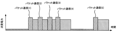
- FIG. 8 is a diagram illustrating a state of power consumption when packet communication frequently occurs in the mobile station when the user is not using in the related art.
- FIG. 9 is a diagram illustrating a state of power consumption when packet communication frequently occurs in the mobile station when the user is not using in the present embodiment.
- the packet communication (1) occurs, and after the packet communication (1) ends, “Monitoring Timer (1)” is started. Before the expiration of “Monitoring ⁇ ⁇ Timer (1)”, the next packet communication (2) occurs. Since packet communication (2) occurred before the expiration of “Monitoring Timer (1)”, the wireless connection maintenance time after the completion of packet communication (2) is set to be long.
- the program of the present invention is a program for a base station apparatus that performs radio communication with a mobile station apparatus, and includes information indicating a use status of the mobile station apparatus together with a request for establishing a wireless connection from the mobile station apparatus.
- the first timer is started at the time when processing for setting a relatively short time in the first timer and transmission of a packet to the mobile station device are completed, and the first timer A control signal is transmitted to the mobile station apparatus when the timer expires, and the computer performs a series of processes of disconnecting the wireless connection with the mobile station apparatus.
- the program of the present invention is a program of a base station apparatus that performs radio communication with a mobile station apparatus, and information indicating a use status of the mobile station apparatus together with a request for establishing a wireless connection from the mobile station apparatus.
- a second timer is set that determines the start timing of C-DRX (CONNECTED Discontinuous Reception) for a relatively long time.
- C-DRX CONNECTED Discontinuous Reception
- a process of setting a relatively short time in the second timer, and a time point when transmission of the packet to the mobile station apparatus ends. And starting the second timer, and performing a series of processes on the computer, including a process of intermittently transmitting a control signal when the second timer expires And characterized in that.
- the program of the present invention provides a process for setting a relatively long time in the first timer when the information indicating the usage status indicates that the mobile station apparatus is in use, and information indicating the usage status Indicates that the mobile station apparatus is not used, it is determined whether a third timer for determining a period for monitoring the occurrence of packet communication has expired, and if the third timer has not expired, A process of setting a relatively long time in the third timer, and setting a relatively short time in the third timer when the third timer has expired. It is characterized by.
- the program of the present invention is a program of a mobile station apparatus that performs radio communication with a base station apparatus, and shows the use status together with a process for determining a user use status and a request for establishing a wireless connection.
- the computer is caused to execute a series of processes of notifying the base station apparatus of information and a process of transitioning to an idle state after receiving a control signal from the base station apparatus.
- the radio communication method of the present invention is a radio communication method of a base station apparatus that performs radio communication with a mobile station apparatus, and uses the mobile station apparatus together with a request for establishing a radio connection from the mobile station apparatus. If the information indicating the status and the information indicating the usage status indicate the use of the mobile station device, a relatively long time is set in the first timer, while the information indicating the usage status is When indicating that the mobile station apparatus is not used, a step of setting a relatively short time in the first timer, and starting the first timer when transmission of a packet to the mobile station apparatus ends. And a step of transmitting a control signal to the mobile station device when the first timer expires to disconnect the wireless connection with the mobile station device.
- the base station apparatus of the present invention is a base station apparatus that performs radio communication with a mobile station apparatus, and includes information indicating a use status of the mobile station apparatus together with a request for establishing a wireless connection from the mobile station apparatus. And when the information indicating the usage status indicates the use of the mobile station device, the relatively long time is set in the first timer, while the information indicating the usage status is the When indicating non-use of a mobile station device, a timer setting unit that sets a relatively short time in the first timer, and starting the first timer when packet transmission to the mobile station device is completed A radio control unit that transmits a control signal to the mobile station apparatus when the first timer expires and disconnects the radio connection with the mobile station apparatus.
- the mobile station apparatus of the present invention is a mobile station apparatus that performs radio communication with a base station apparatus, together with a usage status determination unit that determines the usage status of the user's own device and a request for establishing a wireless connection And a notification unit for notifying the base station device of information indicating a usage state, and a control unit that receives a control signal from the base station device and transitions to an idle state.
- the mobile station starts CDRX and PDCCH is intermittently transmitted step P5 ...
- Mobile station use state determination step P6 determining whether the monitoring timer has expired Judgment step P7 ... Sho rt Release Timer start step P8 ... Long Release Timer start step P9 ...
- Monitoring Timer start step P10 ... Maintain wireless connection step P12 ... Determine whether Release Timer has expired Step P13 ... Set RRC Connection Release to mobile station Send and disconnect wireless connection
Landscapes
- Engineering & Computer Science (AREA)
- Computer Networks & Wireless Communication (AREA)
- Signal Processing (AREA)
- Mobile Radio Communication Systems (AREA)
Abstract
Description
・移動局と基地局の間で無線接続が確立されており、パケット通信が可能。
・基地局からパケット通信を行なうための無線リソースを割り当てられ、PDCCHで通知される。
・パケット通信時以外でも無線接続を維持するためにPDCCHを連続的に受信しているため消費電力は高い。
・移動局と基地局の間で無線接続は確立されておらず、パケット通信はできない。
・パケット通信を行なう際には、無線接続を確立し、“RRC CONNECTED状態”に遷移する必要がある。
・基地局からページング(着信情報)を間欠受信する。
・消費電力は低い。
図1は、第1の実施形態に係る移動局および基地局の動作を示すシーケンスチャートである。移動局は、パケット通信の開始時に、ユーザの移動局の使用状況を基地局に通知する。基地局は、ユーザの使用状況に応じて無線接続の維持時間を決定する。図1において、パケットデータが発生した場合(1)、UE(移動局)は、ユーザの移動局の使用状況、すなわち、“使用している”または“使用していない”を判断する(2)。具体的には、ディスプレイの点灯状態と音声の出力状態を確認する。
第1の実施形態では、図1の(2)において、ユーザの使用状況をディスプレイの状態と音声出力の状態で判断したが、本発明は、これに限定されるわけではなく、これ以外にも、加速度センサの検出状態やバイブレーションの振動状態等により、ユーザの使用状況を判断しても良い。
3GPP標準のLTE方式では、“RRC CONNECTED状態”の移動局の消費電力を低減させるために、C-DRX(CONNECTED Discontinuous Reception、以下、「CDRX」と表記する。)がオプションで標準化されている。通常、“RRC CONNECTED状態”である移動局は、PDCCHを連続して受信しているが、“CDRX状態”の移動局は、一定間隔で受信回路を起動させてPDCCHの受信を行ない、それ以外の時間は受信回路を休止する。すなわち、CDRXは、PDCCHの間欠受信機能である。これにより、基地局から無線リソースを割り当てられた状態(パケット通信が可能な状態)でありながら、消費電力を低く抑えることが可能となる。
ユーザが移動局を使用していない場合でも、例えば、電子メールの連続着信等により、パケット通信が頻繁に発生する可能性がある。本実施形態では、ユーザが使用していない移動局において、パケット通信の終了後、パケット通信の有無を一定期間モニタリングし、一定時間以内にパケット通信が発生した場合は、無線接続の維持時間を長く設定する。
11…無線通信部
13…タイマー設定部
15…無線制御部
17…タイマー
19…制御バス
20…移動局装置
21…使用状況判定部
23…通知部
25…制御部
27…制御バス
ステップS5…移動局の使用状態の判断
ステップS6…Short Release Timerの開始
ステップS7…Long Release Timerの開始
ステップS8…PDCCHを送信
ステップS11…RRC Connection Releaseを移動局に送信し、無線接続を切断
ステップT5…移動局の使用状態の判断
ステップT6…Short Release Timerの開始
ステップT7…Long Release Timerの開始
ステップT8…PDCCHを送信
ステップT11…移動局にCDRXを開始させ、PDCCHを間欠的に送信
ステップP5…移動局の使用状態の判断
ステップP6…Monitoring Timerが満了しているかどうかを判断
ステップP7…Short Release Timerの開始
ステップP8…Long Release Timerの開始
ステップP9…Monitoring Timerの開始
ステップP10…無線接続を維持
ステップP12…Release Timerが満了しているかどうかを判断
ステップP13…RRC Connection Releaseを移動局に送信し、無線接続を切断
Claims (5)
- 移動局装置と無線通信を行なう基地局装置のプログラムであって、
前記移動局装置から無線接続を確立するためのリクエストと共に、前記移動局装置の使用状況を示す情報を取得する処理と、
前記使用状況を示す情報が、前記移動局装置の使用を示す場合、相対的に長い時間を第1のタイマーに設定する一方、前記使用状況を示す情報が、前記移動局装置の非使用を示す場合、相対的に短い時間を前記第1のタイマーに設定する処理と、
前記移動局装置に対するパケットの送信が終了した時点で前記第1のタイマーを起動させ、前記第1のタイマーが満了した時点で前記移動局装置に対して制御信号を送信して前記移動局装置との無線接続を切断する処理と、の一連の処理をコンピュータに実行させることを特徴とするプログラム。 - 移動局装置と無線通信を行なう基地局装置のプログラムであって、
前記移動局装置から無線接続を確立するためのリクエストと共に、前記移動局装置の使用状況を示す情報を取得する処理と、
前記使用状況を示す情報が、前記移動局装置の使用を示す場合、相対的に長い時間をC-DRX(CONNECTED Discontinuous Reception)の開始タイミングを定める第2のタイマーを設定する一方、前記使用状況を示す情報が、前記移動局装置の非使用を示す場合、相対的に短い時間を前記第2のタイマーに設定する処理と、
前記移動局装置に対するパケットの送信が終了した時点で前記第2のタイマーを起動させ、前記第2のタイマーが満了した時点で制御信号を間欠的に送信する処理と、の一連の処理をコンピュータに実行させることを特徴とするプログラム。 - 前記使用状況を示す情報が、前記移動局装置の使用中を示す場合、相対的に長い時間を前記第1のタイマーに設定する処理と、
前記使用状況を示す情報が、前記移動局装置の非使用を示す場合、パケット通信の発生をモニタリングする期間を定める第3のタイマーが満了しているかどうかを判断し、前記第3のタイマーが満了していない場合は、相対的に長い時間を前記第3のタイマーに設定する一方、前記第3のタイマーが満了している場合は、相対的に短い時間を前記第3のタイマーに設定する処理と、を更に含むことを特徴とする請求項1記載のプログラム。 - 基地局装置と無線通信を行なう移動局装置のプログラムであって、
ユーザの使用状況を判定する処理と、
無線接続を確立するためのリクエストと共に、前記使用状況を示す情報を前記基地局装置に通知する処理と、
前記基地局装置から制御信号を受信してアイドル状態に遷移する処理と、の一連の処理をコンピュータに実行させることを特徴とするプログラム。 - 移動局装置と無線通信を行なう基地局装置であって、
前記移動局装置から無線接続を確立するためのリクエストと共に、前記移動局装置の使用状況を示す情報を取得する無線通信部と、
前記使用状況を示す情報が、前記移動局装置の使用を示す場合、相対的に長い時間を第1のタイマーに設定する一方、前記使用状況を示す情報が、前記移動局装置の非使用を示す場合、相対的に短い時間を前記第1のタイマーに設定するタイマー設定部と、
前記移動局装置に対するパケットの送信が終了した時点で前記第1のタイマーを起動させ、前記第1のタイマーが満了した時点で前記移動局装置に対して制御信号を送信して前記移動局装置との無線接続を切断する無線制御部と、を備えることを特徴とする基地局装置。
Priority Applications (2)
| Application Number | Priority Date | Filing Date | Title |
|---|---|---|---|
| US14/905,473 US9820227B2 (en) | 2013-08-30 | 2014-07-28 | Program and base station apparatus |
| CN201480047591.6A CN105493619B (zh) | 2013-08-30 | 2014-07-28 | 程序和基站装置 |
Applications Claiming Priority (2)
| Application Number | Priority Date | Filing Date | Title |
|---|---|---|---|
| JP2013180288A JP6226458B2 (ja) | 2013-08-30 | 2013-08-30 | プログラムおよび基地局装置 |
| JP2013-180288 | 2013-08-30 |
Publications (1)
| Publication Number | Publication Date |
|---|---|
| WO2015029668A1 true WO2015029668A1 (ja) | 2015-03-05 |
Family
ID=52586242
Family Applications (1)
| Application Number | Title | Priority Date | Filing Date |
|---|---|---|---|
| PCT/JP2014/069865 Ceased WO2015029668A1 (ja) | 2013-08-30 | 2014-07-28 | プログラムおよび基地局装置 |
Country Status (4)
| Country | Link |
|---|---|
| US (1) | US9820227B2 (ja) |
| JP (1) | JP6226458B2 (ja) |
| CN (1) | CN105493619B (ja) |
| WO (1) | WO2015029668A1 (ja) |
Families Citing this family (3)
| Publication number | Priority date | Publication date | Assignee | Title |
|---|---|---|---|---|
| US10499451B2 (en) * | 2014-06-13 | 2019-12-03 | Apple Inc. | Adaptive C-DRX management |
| CN114503680B (zh) * | 2019-09-29 | 2024-05-07 | 高通股份有限公司 | 无线电资源控制(rrc)连接释放定时器 |
| US11622414B2 (en) * | 2020-07-17 | 2023-04-04 | Qualcomm Incorporated | Enhanced connection release techniques for wireless communications systems |
Family Cites Families (14)
| Publication number | Priority date | Publication date | Assignee | Title |
|---|---|---|---|---|
| CN101411095B (zh) * | 2006-03-28 | 2013-06-19 | 三星电子株式会社 | 用于移动通信系统中的连接终端的非连续接收的方法和设备 |
| CN101483446B (zh) * | 2008-01-08 | 2014-07-30 | 株式会社Ntt都科摩 | 动态控制不连续接收的方法和装置 |
| CN101541067B (zh) * | 2008-03-21 | 2011-02-02 | 凌阳电通科技股份有限公司 | 在非连续接收机制中停留在短周期的方法 |
| TW201008234A (en) | 2008-08-12 | 2010-02-16 | Acer Inc | Energy-saving method for handheld Internet accessing device, the handheld Internet accessing device, and the real-time message system |
| CN102123447B (zh) * | 2010-01-08 | 2015-12-16 | 中兴通讯股份有限公司 | 一种不连续接收方法及系统 |
| US20110176466A1 (en) * | 2010-01-21 | 2011-07-21 | Bengt Lindoff | Micro-Sleep Techniques in LTE Receivers |
| CN102300297B (zh) * | 2011-09-07 | 2014-01-15 | 大唐移动通信设备有限公司 | 一种演进型基站的非连续接收的判决方法及装置 |
| JP5678194B2 (ja) | 2011-09-16 | 2015-02-25 | 株式会社Nttドコモ | 基地局及び通信制御方法 |
| CN104041113A (zh) * | 2011-11-15 | 2014-09-10 | 诺基亚公司 | 间歇性业务的无线电使用优化 |
| US9723558B2 (en) * | 2012-04-27 | 2017-08-01 | Qualcomm Incorporated | Method and apparatus for signaling in dense network operations |
| US9155004B2 (en) * | 2012-08-31 | 2015-10-06 | Apple Inc. | Fast reselection from a current cell to a higher-priority cell in wireless communication |
| US9445365B2 (en) * | 2013-01-14 | 2016-09-13 | Apple Inc. | Reducing power consumption in voice over LTE terminals using semi persistent scheduling in connected discontinuous reception mode |
| US9872333B2 (en) * | 2013-04-03 | 2018-01-16 | Apple Inc. | Method and system for scheduling application-generated data requests in discontinuous reception (DRX) mode |
| CN105144768B (zh) * | 2013-04-26 | 2019-05-21 | 英特尔Ip公司 | 频谱共享情境中的共享频谱重新分配 |
-
2013
- 2013-08-30 JP JP2013180288A patent/JP6226458B2/ja active Active
-
2014
- 2014-07-28 CN CN201480047591.6A patent/CN105493619B/zh active Active
- 2014-07-28 WO PCT/JP2014/069865 patent/WO2015029668A1/ja not_active Ceased
- 2014-07-28 US US14/905,473 patent/US9820227B2/en not_active Expired - Fee Related
Non-Patent Citations (6)
| Title |
|---|
| ALCATEL -LUCENT SHANGHAI BELL ET AL.: "The handover in long connected mode for MTCe- SDDTE", R2-132623, 3GPP, 9 August 2013 (2013-08-09) * |
| CATT: "Analysis ot UE Assistance Information tor eDDA", R2-122159, 3GPP, 15 May 2012 (2012-05-15) * |
| ERICSSON ET AL.: "Discussion on UE mobility assistance information", R2-124038, 3GPP, 7 August 2012 (2012-08-07) * |
| HUAWEI ET AL.: "Further analysis on the usage of the PPI to save UE power", R2-131975, 3GPP, 10 May 2013 (2013-05-10) * |
| INTEL CORPORATION: "Evaluation of RRC signalling overhead and state selection during mobility", R2-122841, 3GPP, 15 May 2012 (2012-05-15) * |
| LG ELECTRONICS INC.: "Discussion on Assistance Information", R2-121313, 3GPP, 20 March 2012 (2012-03-20) * |
Also Published As
| Publication number | Publication date |
|---|---|
| JP2015050577A (ja) | 2015-03-16 |
| CN105493619A (zh) | 2016-04-13 |
| CN105493619B (zh) | 2019-03-19 |
| JP6226458B2 (ja) | 2017-11-08 |
| US9820227B2 (en) | 2017-11-14 |
| US20160286486A1 (en) | 2016-09-29 |
Similar Documents
| Publication | Publication Date | Title |
|---|---|---|
| US11871349B2 (en) | Sleep method for terminal device and apparatus | |
| CN105684522B (zh) | 在通信网络中使用的网络节点和移动设备、操作其的方法以及计算机程序产品 | |
| JP6096775B2 (ja) | 不連続受信(drx)と共に構成されるユーザ機器のアクティブ時間ステータスに基づくアップリンク制御シグナリングを送信すべきかの決定 | |
| TWI475919B (zh) | 暫停一無線通信系統中之一連接 | |
| JP6172544B2 (ja) | パラメータを設定するための方法、基地局、及びユーザ機器 | |
| CN106465261B (zh) | 用户设备、蜂窝通信网络节点和控制用户设备的操作的方法 | |
| EP2983416B1 (en) | Paging method, apparatus, and system | |
| AU2013322501B2 (en) | Power preference indicator timer | |
| US9445364B2 (en) | Systems and methods for blocking excessive transmitter message signaling | |
| KR102240644B1 (ko) | 데이터 전송/수신 장치 및 방법, 및 통신 시스템 | |
| WO2018107498A1 (zh) | 用于非连续接收的方法和装置 | |
| CN109076494B (zh) | 在寻呼上下文中的无线电网络节点、核心网络节点和其中执行的方法 | |
| CN110268763B (zh) | 接收方案 | |
| CN116368823A (zh) | 用于多播及广播服务的方法及设备 | |
| TW201517644A (zh) | 微量資料傳輸方法及使用者設備 | |
| CN103703817A (zh) | 通信方法、通信装置及基站 | |
| WO2011134427A1 (zh) | 一种离线检测的方法、装置及系统 | |
| EP2829144B1 (en) | System and method for supporting switching between a packet-switched network and a circuit-switched network | |
| WO2015065457A1 (en) | User equipment power optimization | |
| JP6226458B2 (ja) | プログラムおよび基地局装置 | |
| CN104186013A (zh) | 一种数据处理装置及方法 | |
| JP7722719B2 (ja) | 端末装置及び通信のための方法 | |
| US20150071148A1 (en) | State transition timer setting system, mobile equipment, mobile communication system, and state transition timer setting method | |
| CN110621077A (zh) | 上行数据传输的确认装置、设备和方法 | |
| CN113348719B (zh) | 一种监听方法及装置 |
Legal Events
| Date | Code | Title | Description |
|---|---|---|---|
| WWE | Wipo information: entry into national phase |
Ref document number: 201480047591.6 Country of ref document: CN |
|
| 121 | Ep: the epo has been informed by wipo that ep was designated in this application |
Ref document number: 14839872 Country of ref document: EP Kind code of ref document: A1 |
|
| WWE | Wipo information: entry into national phase |
Ref document number: 14905473 Country of ref document: US |
|
| NENP | Non-entry into the national phase |
Ref country code: DE |
|
| 122 | Ep: pct application non-entry in european phase |
Ref document number: 14839872 Country of ref document: EP Kind code of ref document: A1 |