WO2015025352A1 - 薬剤供給装置、該薬剤供給装置を用いた排水処理装置及び排水処理設備 - Google Patents
薬剤供給装置、該薬剤供給装置を用いた排水処理装置及び排水処理設備 Download PDFInfo
- Publication number
- WO2015025352A1 WO2015025352A1 PCT/JP2013/072098 JP2013072098W WO2015025352A1 WO 2015025352 A1 WO2015025352 A1 WO 2015025352A1 JP 2013072098 W JP2013072098 W JP 2013072098W WO 2015025352 A1 WO2015025352 A1 WO 2015025352A1
- Authority
- WO
- WIPO (PCT)
- Prior art keywords
- drug
- supply device
- water
- treated
- medicine
- Prior art date
- Legal status (The legal status is an assumption and is not a legal conclusion. Google has not performed a legal analysis and makes no representation as to the accuracy of the status listed.)
- Ceased
Links
Images







Classifications
-
- C—CHEMISTRY; METALLURGY
- C02—TREATMENT OF WATER, WASTE WATER, SEWAGE, OR SLUDGE
- C02F—TREATMENT OF WATER, WASTE WATER, SEWAGE, OR SLUDGE
- C02F1/00—Treatment of water, waste water, or sewage
- C02F1/68—Treatment of water, waste water, or sewage by addition of specified substances, e.g. trace elements, for ameliorating potable water
- C02F1/685—Devices for dosing the additives
- C02F1/688—Devices in which the water progressively dissolves a solid compound
-
- C—CHEMISTRY; METALLURGY
- C02—TREATMENT OF WATER, WASTE WATER, SEWAGE, OR SLUDGE
- C02F—TREATMENT OF WATER, WASTE WATER, SEWAGE, OR SLUDGE
- C02F1/00—Treatment of water, waste water, or sewage
- C02F1/52—Treatment of water, waste water, or sewage by flocculation or precipitation of suspended impurities
- C02F1/5236—Treatment of water, waste water, or sewage by flocculation or precipitation of suspended impurities using inorganic agents
-
- Y—GENERAL TAGGING OF NEW TECHNOLOGICAL DEVELOPMENTS; GENERAL TAGGING OF CROSS-SECTIONAL TECHNOLOGIES SPANNING OVER SEVERAL SECTIONS OF THE IPC; TECHNICAL SUBJECTS COVERED BY FORMER USPC CROSS-REFERENCE ART COLLECTIONS [XRACs] AND DIGESTS
- Y02—TECHNOLOGIES OR APPLICATIONS FOR MITIGATION OR ADAPTATION AGAINST CLIMATE CHANGE
- Y02W—CLIMATE CHANGE MITIGATION TECHNOLOGIES RELATED TO WASTEWATER TREATMENT OR WASTE MANAGEMENT
- Y02W10/00—Technologies for wastewater treatment
- Y02W10/30—Wastewater or sewage treatment systems using renewable energies
- Y02W10/37—Wastewater or sewage treatment systems using renewable energies using solar energy
Definitions
- the present invention relates to a drug supply device that elutes a drug into a liquid, a wastewater treatment device and a wastewater treatment facility using the drug supply device.
- Wastewater flowing into dam lakes, etc. was treated to below the drainage standard, 16 mg / L (average daily 8 mg / L) under the general drainage standard, and 30 mg / L (daily average 248 mg / L) under the provisional drainage standard (livestock industry). Although it is water, it is necessary to make phosphoric acid in inflow wastewater 1 mg / L or less and phosphoric acid 0.01 mg / L or less in a dam lake or the like in order to suppress the occurrence of water-bloom.
- the concentration of the drug is obtained by passing the treated water through a filling tank filled with a hardly soluble calcium-containing material such as gypsum and continuously eluting the calcium content into the treated water.
- a technique for reducing management and replenishment costs see, for example, Patent Document 2.
- JP 2004-261640 A JP 2001-276850 A Japanese Patent Laid-Open No. 5-290533
- a general wastewater treatment device In addition to the removal of phosphoric acid from wastewater, a general wastewater treatment device requires a chemical injection device, a measurement, a control device, and the like in addition to a reaction tank, and the wastewater treatment device becomes large. There is a strong demand for simple wastewater treatment with a simple device, especially in the case of further purifying water within the wastewater standards.
- An object of the present invention is to provide a medicine supply device capable of eluting and supplying a medicine in a compact and efficient manner without using a device such as a stirrer, and a wastewater treatment with maintenance-free or easy maintenance using the medicine supply device. It is to provide equipment and wastewater treatment equipment.
- the present invention comprises a flow path for circulating a liquid, an opening on the upper surface, a drug loading section provided so that the opening faces the flow path and the flow path expands rapidly at the opening,
- the drug supply device is characterized by flowing a liquid, forcibly generating a turbulent flow in the opening, and using the turbulent flow to elute the drug loaded in the drug loading unit.
- the flow path is rapidly expanded at the opening of the drug loading unit, the liquid is flowed to forcibly generate turbulent flow, and the turbulent flow is used to load the drug loading unit. Since the drug is eluted, the transfer (supply) and stirring of the drug are performed together, which is very efficient. If the size of the drug loading section is about several mL to several hundred mL, turbulence can be easily generated even with a small flow rate.
- the turbulent flow means a flow state in which a large turbulence occurs in the liquid such as a vortex.
- the drug supply device of the present invention does not require a stirrer or the like for eluting the drug, so that the device can be made compact.
- the drug supply device of the present invention is characterized in that the drug loaded in the drug loading unit is a hardly soluble solid drug.
- the drug loaded in the drug loading unit is a hardly soluble solid drug
- the drug can be gradually eluted in the liquid over a long period of time, and can be used continuously for a long period of time. It becomes possible.
- the medicine supply device of the present invention is characterized by comprising turbulent flow generation promoting means for accelerating the generation of turbulent flow at the opening.
- the drug supply device of the present invention is characterized in that a turbulent flow is generated by causing a pressure difference in the liquid flowing through the flow path.
- the drug supply device of the present invention is characterized in that the turbulent flow generation promoting means is a throttle.
- the medicine supply device includes the turbulent flow generation promoting means for accelerating the generation of the turbulent flow at the opening, the turbulent flow can be reliably generated at the opening and the turbulent flow is increased. And the drug can be eluted more efficiently.
- the present invention is a drug supply device in which a plurality of the drug supply devices are arranged in series and the amount of drug elution is adjusted according to the number of the devices to be arranged.
- a plurality of drug supply devices are arranged in series, and the elution amount of the drug is adjusted according to the number of arranged drugs. Therefore, the elution amount of the drug is easily adjusted, and the elution amount of the drug is adjusted. Measurement equipment, control equipment, etc. are unnecessary.
- the present invention is a drug supply device in which a plurality of the drug supply devices are arranged in parallel.
- the supply amount of the drug can be easily increased. Further, when such a chemical supply device is used as a chemical supply device / reaction tank of a wastewater treatment device, even if clogging occurs in one flow path, it is possible to perform wastewater treatment in another flow path. Easy to use.
- the medicine supply device of the present invention is characterized in that the medicine loading section is arranged without a gap.
- the apparatus since the drug loading section is arranged without a gap, the apparatus can be made compact.
- the present invention is a drug supply device, wherein the drug supply devices are stacked in multiple stages.
- the medicine supply devices are stacked in multiple stages, the amount of medicine supplied can be easily increased. Even if the supply amount is increased, there are few spots for drug elution, and the apparatus can be made compact because the drug can be eluted efficiently.
- the drug supply device of the present invention further includes a flow rate adjusting means for adjusting the flow rate of the liquid flowing through the flow path, and the elution amount of the drug can be adjusted by adjusting the flow rate with the flow rate adjusting means.
- the drug elution amount can be adjusted by adjusting the flow rate by the flow rate adjusting means, the drug elution amount can be easily adjusted.
- the drug contains an elution amount adjusting agent for adjusting the elution amount of the main agent in addition to the main agent.
- the drug since the drug includes an elution amount regulator that adjusts the elution amount of the main agent in addition to the main agent, the sustained release of the drug can be controlled, and the maintenance period can be set to some extent freely. .
- the medicine supply device of the present invention is characterized in that the medicine contains powder particles, and the medicine elutes to release the powder particles, and the discharged powder particles are turbulently acted on the surface of the medicine. And the elution of the drug is promoted.
- the medicine contains powder particles, and the medicine elutes to release the powder particles, and the discharged powder particles erode the surface of the medicine by the action of turbulent flow. Since the elution of the drug is promoted, the drug can be eluted more efficiently.
- the discharged granular material stops at the medicine loading section and does not flow out from the medicine loading section.
- the discharged granular material stops at the drug loading portion and does not flow out from the drug loading portion, the effect of the granular material can be maintained until the drug is completely eluted.
- the liquid flowing in the flow path holds powder particles, and the powder particles erodes the surface of the drug by the action of turbulent flow, and the elution of the drug is promoted.
- the liquid flowing in the flow path holds the particulate matter, and the particulate matter erodes the surface of the medicine by the action of turbulent flow, and the elution of the medicine is promoted. Can be eluted.
- the present invention includes the chemical supply device, the chemical supply device is loaded with a chemical necessary for removing an object to be processed, and water to be treated is supplied to the chemical supply device.
- the wastewater treatment apparatus is characterized in that the treatment object is removed by causing the chemical to act on the material.
- the object to be treated is any one of phosphoric acid, boron, and fluorine
- the drug contains a poorly water-soluble calcium compound, and the object to be treated and the hardly water-soluble substance. It reacts with the calcium component eluted from the water-soluble calcium compound to form a water-insoluble calcium compound, and the object to be treated in the water to be treated is removed.
- the wastewater treatment apparatus is characterized in that the chemical further contains a pH adjusting agent.
- the object to be treated is phosphoric acid
- the water-insoluble calcium compound is hydroxyapatite
- the poorly water-soluble calcium compound and the pH adjuster are calcium hydroxide
- the drug is characterized in that at least calcium oxide, a seed crystal composed of hydroxyapatite, and water are kneaded and loaded into the drug loading unit and then solidified.
- the chemical is further added with an elution amount adjusting agent during the kneading.
- the elution amount regulator is gypsum and / or starch.
- the hydroxyapatite grown with the seed crystal and the seed crystal as a nucleus does not flow out from the drug loading section.
- the chemical supply device can be suitably used as a chemical supply device of a wastewater treatment device, and further as a chemical supply device and reaction tank.
- the material to be treated is phosphoric acid
- the hydroxyapatite that has grown from seed crystals and seed crystals as nuclei does not flow out of the drug loading part. Therefore, after the drug has completely eluted, the hydroxyapatite remains in the drug loading part. It is very easy to collect.
- the object to be treated contains two or more of phosphoric acid, boron, and fluorine
- the drug contains a poorly water-soluble calcium compound, and two or more of phosphoric acid, boron, and fluorine.
- a calcium component eluted from the sparingly water-soluble calcium compound to produce a water-insoluble calcium compound, and the object to be treated in the water to be treated is simultaneously treated.
- a flocculant or a flocculant and a flocculant aid are further added to remove the object to be treated from the water to be treated.
- an adsorbent is further added to remove an object to be treated in the water to be treated.
- the wastewater treatment apparatus of the present invention further comprises a pH meter for measuring the pH of the water to be treated after the material to be treated is removed, the material to be treated is phosphoric acid, The pH of the solution is measured, and the phosphoric acid concentration in the treated water is calculated.
- the waste water treatment apparatus of the present invention is characterized in that the flow rate of water to be treated supplied to the chemical supply device is adjusted by the flow rate adjusting means based on the phosphoric acid concentration calculated from the measured value of the pH meter.
- the flow rate is adjusted by the flow rate adjusting means based on the phosphoric acid concentration calculated from the measured value of the pH meter, it is relatively inexpensive so that the phosphoric acid concentration in the water to be treated becomes a predetermined concentration. Automatic control can be performed using a simple pH meter.
- the present invention includes the waste water treatment apparatus, wherein the chemical supply apparatus also serves as a reaction tank, and further, a precipitation tank that precipitates and separates a reaction product generated in the chemical loading unit, and is installed downstream of the precipitation tank. And a pH adjustment tank that adjusts the pH of the water to be treated with a neutralizing agent.
- the neutralizing agent is humic acid
- the pH adjustment tank is filled with peat moss containing decaying fungi, and the rot fungus is caused to act on the peat moss to generate the humic acid
- the peat moss is brought into contact with the water to be treated, and the water to be treated is neutralized with the humic acid to adjust the pH.
- the wastewater treatment apparatus of the present invention comprises an environment forming means that uses the water to be treated, brings the peat moss into a moist and aerobic state, and places the peat moss in a high humidity and aerobic state in which the rot fungi grow well.
- the waste water treatment apparatus uses a chemical supply apparatus capable of gradually eluting the chemical over a long period of time in the reaction tank, and uses peat moss capable of growing rot fungi in the pH adjustment tank.
- the reaction tank and the pH adjustment tank can be continuously operated without performing maintenance for a long period of time, the entire apparatus can be continuously operated without performing maintenance for a long period of time.
- the waste water treatment apparatus of this invention does not require a special stirring apparatus, a measurement apparatus, a control apparatus, etc. in a reaction tank and a pH adjustment tank, it can be made compact.
- the waste water treatment apparatus of the present invention is further characterized by comprising a circulation means for returning a part of the water to be treated before being discharged from the settling tank and flowing into the pH adjustment tank to the chemical supply apparatus.
- the object to be treated can be sufficiently removed. Moreover, when using the liquid containing a granular material, since the granular material can be circulated and reused, the usage-amount of a granular material can be reduced.
- the present invention also includes the waste water treatment device, a housing that houses the waste water treatment device, a float that floats the housing on the water to be treated, and a supply unit that supplies the water to be treated to the waste water treatment device. It is the waste water treatment facility characterized by including.
- the supply means is a water wheel or a pump, and is provided with a solar battery power generation device that supplies a driving power source for the water wheel or the pump.
- the waste water treatment facility of the present invention is installed in a waste water storage tank, a lake or a dam lake, and is movable by the supply means.
- the wastewater treatment facility includes a wastewater treatment device, a housing that houses the wastewater treatment device, a float that floats the housing on the treated water, and a supply unit that supplies the treated water to the wastewater treatment device.
- the supply means is a water wheel or pump, and is equipped with a solar cell power generation device that supplies power for driving the water wheel or pump, and therefore, after being installed in a lake or dam lake, the waste water treatment is continued for a long time without maintenance. Can be done.
- a medicine supply device that can elute and supply medicine in a compact and efficient manner without using a device such as a stirrer.
- medical agent supply apparatus can be used suitably for a waste water treatment apparatus and waste water treatment equipment.
- chemical supply devices, wastewater treatment devices and wastewater treatment facilities using them can be operated without maintenance for a long time or with simple maintenance. Can be suitably used.
- FIG. 8 It is a schematic block diagram of the waste water treatment facility 8 which is 8th Embodiment of this invention. It is a graph which shows the relationship between pH and phosphoric acid concentration. It is a schematic block diagram of the waste water treatment facility 9 which is 9th Embodiment of this invention. It is a schematic block diagram of the waste water treatment facility 10 which is 10th Embodiment of this invention. It is a top view of the waste water treatment facility 10 of FIG. It is a schematic block diagram of the waste water treatment facility 11 which is 11th Embodiment of this invention. It is a schematic block diagram of the testing apparatus 100 of the chemical
- the drug supply device including a single drug loader is a cell drug supply device, a drug supply device in which a plurality of cell drug supply devices are arranged in series is a serial cell drug supply device, and a serial cell drug supply.
- a drug supply device in which a plurality of devices are arranged is referred to as a unit drug supply device, and a drug supply device in which unit drug supply devices are stacked in multiple stages is referred to as a multistage unit drug supply device.
- FIG. 1 is a cross-sectional view of a main part of a cell medicine supply device 1 according to the first embodiment of the present invention.
- the cell medicine supply device 1 includes a flow path 21 through which a liquid 90 is circulated and a single medicine loading section 23 that loads a medicine 31, and an upper surface 26 of the medicine loading section 23 is an opening 27 that faces the flow path 21.
- turbulent flow is forcedly generated in the opening 27, and the drug 31 loaded in the drug loading unit 23 is eluted (dissolved) using this turbulent flow.
- the turbulent flow refers to a flow state in which a large turbulence occurs in the liquid, and a vortex flow 95 is represented.
- a turbulent flow state in which the vortex flow 95 is formed is preferable.
- the turbulent flow will be described as the vortex flow 95.
- the drug loading unit 23 is attached so as to be orthogonal to the flow path 21, and the drug 31 is filled less than the full depth of the drug loading unit 23, that is, so that a space portion remains above the drug loading unit 23. Is done. For this reason, in the medicine loading unit 23, the cross-sectional area is rapidly increased as compared with the cross-sectional area of the front and rear flow paths 21.
- the flow rate rapidly decreases in the drug loading unit 23, so that a pressure difference occurs between the liquid before and after the drug loading unit 23, as shown in FIG.
- the flow direction of the liquid 90 in the vicinity of the surface of the medicine 31 is opposite to the flow direction of the liquid 90 flowing through the flow path 21, and a vortex 95 is generated.
- the shape of the cell medicine supply device 1 is not limited to a specific shape, and can be appropriately determined according to the application.
- the width of the flow path 21 is about several mm to several tens mm, or the capacity of the drug loading unit 23 is about several mL to several hundred mL.
- the depth of the medicine loading unit 23 is set within a range where the vortex 95 can reach. The range in which the vortex 95 reaches is affected by the size of the vortex 95, and the size of the vortex 95 depends on the flow velocity of the liquid 90 flowing through the flow path 21, the length of the opening 27, and the depth.
- the cell medicine supply device 1 attempts to elute the medicine 31 by positively flowing the liquid 90 on the surface of the medicine 31 in contact with the liquid 90, the remaining amount of the medicine 31 is reduced. In this case, it is important that the vortex 95 is in direct contact with the surface of the medicine 31.
- the length of the drug loading section 23 is a length at which the vortex 95 is formed and should not be extremely long. Furthermore, it is preferable to determine the total length of the drug loading portion 23 so that the vortex 95 is uniformly formed on the surface of the drug 31.
- the material of the cell medicine supply device 1 is not limited to a specific material, and can be appropriately determined depending on the liquid to be circulated, the medicine to be loaded, the use environment, and the like.
- the cell drug supply device 1 may be configured such that the flow channel 21 and the drug loading unit 23 are detachable (detachable), and the flow channel 21 and the drug loading unit 23 are fixed (integrated) so as not to be removable. It may be. Furthermore, it is good also considering the ceiling part 22 as a different body (separate type).
- the liquid 90 is not limited to a specific one, and can be appropriately determined according to the application.
- the drug 31 is not limited to a specific one, and can be appropriately determined according to the use. However, when a solid and poorly soluble drug is used, the surface of the drug 31 is gradually eluted into the liquid 90, Since it can be used continuously for a long period of time, it is preferable. In particular, since the cell drug supply device 1 of the present invention actively generates a vortex 95 and uses this vortex 95 to elute the drug 31 loaded in the drug loading unit 23, it is solid and hardly soluble. It can be suitably used for elution of the drug 31. The eddy current 95 is not only excellent in diffusion performance but also can be expected to erode the surface of the drug 31, so that the elution rate of the drug 31 can be increased. Note that the poorly soluble drug 31 can be regarded as a slightly soluble drug or a slowly soluble drug.
- the medicine 31 is loaded so as not to flow out of the medicine loading section 23 due to the flow of the liquid 90 so that the medicine 31 can be used continuously.
- the loading of the medicine 31 can be performed as follows.
- the drug loading unit 23 is detachable, the drug loading unit 23 may be attached to the flow path 21 after loading the drug 31 in the drug loading unit 23.
- the ceiling portion 22 is a separate type, the ceiling portion 22 may be attached after the medicine 31 is loaded in the medicine loading portion 23.
- the cell medicine supply device 1 is an integrated type, the medicine 31 may be poured from the flow path 21 and the injection hole (not shown) is closed after injecting from the ceiling portion 22 of the cell medicine supply device 1 or the bottom of the medicine loading portion 23. Such a method can be adopted.
- the predetermined speed is a speed at which the vortex 95 is generated in the opening 27 of the medicine loading section 23. Since the medicine 31 dissolved in the liquid 90 is conveyed to the downstream side, it can be used for various purposes.
- the cell drug supply device 1 is a device that uses flow mixing that forcibly generates a disturbance in the flow of the liquid 90 to be supplied and uses the disturbance to elute (dissolve) the drug.
- Such a cell drug supply device 1 is excellent in drug elution (dissolution) ability and is very efficient because the transfer (supply) and stirring of the drug 31 are performed together.
- a device such as a stirrer for elution (dissolution) of the drug 31
- the apparatus can be made compact.
- the cell medicine supply device 1 can maintain the concentration (elution) of the medicine 31 almost constant if the flow rate of the liquid 90 is constant, so that the concentration management can be performed without using an expensive measuring device or the like. Further, maintenance is not required until the drug 31 is completely dissolved (dissolved), and after the drug 31 has been completely dissolved (dissolved), it can be used repeatedly if the drug 31 is loaded again.
- the use of the cell drug supply device 1 is not limited to a specific use, and for example, it is used for various applications for elution (dissolution) of a drug into a liquid, such as wastewater treatment, tap water modification, and dissolution of a detergent. In particular, it can be suitably used for applications in which a drug is gradually eluted (dissolved) in a liquid. If attention is paid to drug elution (dissolution), the cell drug supply device 1 can be said to be a drug dissolution device.
- FIG. 2 is a cross-sectional view of the main part of the cell medicine supply device 2 according to the second embodiment of the present invention.
- the same components as those of the cell medicine supply device 1 shown in the first embodiment are denoted by the same reference numerals and description thereof is omitted.
- the cell drug supply device 2 of the second embodiment has the same basic configuration as the cell drug supply device 1 of the first embodiment, but eddy current generation promoting means for generating a vortex 95 at the opening 27 of the drug loading unit 23. Is provided.
- FIG. 2 (a) is a cross-sectional view of the main part showing the cell medicine supply device 2 provided with fins 41 on the upstream side of the medicine loading section 23 as eddy current generation promoting means.
- the fin 41 is flat and is provided on the upstream side of the opening, and is provided so as to shield a part of the flow channel 21 in the width direction with the tip inclined to the downstream side. Squeezing locally.
- the fins 41 may be integrally formed with the cell medicine supply device 2 or may be separately bonded with an adhesive or the like.
- the angle, height, and thickness of the fin 41 are not limited to specific ones, and can be determined as appropriate so that the vortex 95 is effectively generated on the surface of the drug 31.
- the fins 41 may be provided not in the entire width of the flow path 21 but in only a part thereof.
- the shape of the fin 41 is not limited to a specific shape, and may be, for example, a curved shape such as a V shape or a wave shape.
- the material of the fin 41 can be appropriately determined according to the liquid, the medicine, the use environment, etc., as in the cell medicine supply device 1 of the first embodiment.
- FIG. 2B is a cross-sectional view of the main part showing the cell drug supply device 2 provided with fins 41 on the downstream side of the drug loading unit 23 as eddy current generation promoting means.
- FIG. 2C is a cross-sectional view of the main part showing the cell drug supply device 2 in which the fins 41 are provided on the ceiling portion 22 of the flow path 21 on the upstream side of the drug loading unit 23 as eddy current generation promoting means.
- the position where the fins 41 are provided is not limited to a specific position, and can be determined as appropriate so that the vortex 95 is effectively generated on the surface of the medicine 31.
- the attachment position of the fin 42 is not limited to a specific position, and can be determined as appropriate so that the vortex 95 is effectively generated on the surface of the medicine 31.
- FIG. 2 (g) is a cross-sectional view of the main part showing the cell drug supply device 2 in which the convex portion 43 is provided on the ceiling portion 22 of the flow path 21 as the eddy current generation promoting means.
- the convex portion 43 is formed in a dome shape at the center of the medicine loading portion 23, but is not limited to this, and the position, shape, width, height, material, etc. are the same as those of the fins 41, 42. It can be determined as appropriate so that the vortex 95 is effectively generated on the surface of the medicine 31.
- the cell drug supply device 2 of the second embodiment locally restricts the flow path 21 by the eddy current generation promoting means, causes a pressure difference in the liquid 90, and causes the vortex 95 in the opening 27 of the drug loading unit 23 to flow.
- the elution of the drug 31 can be promoted by promoting the generation or increasing the vortex.
- a plurality of eddy current generation promoting means may be used in combination.
- FIG. 3 is a cross-sectional view of the main part of the serial cell drug supply device 3 according to the third embodiment of the present invention.
- 3A is a cross-sectional view of the main part showing the serial cell drug supply device 3 arranged in series in a state where the drug loading units 23 are adjacent to each other, and
- FIG. It is principal part sectional drawing which shows the serial cell chemical
- the same components as those of the cell medicine supply device 1 shown in the first embodiment are denoted by the same reference numerals and description thereof is omitted.
- each drug loading unit 23 is loaded with a drug 31.
- the dissolution of the medicine 31 is promoted by the generation of a vortex 95 as the liquid 90 flows.
- the elution amount of the drug 31 into the liquid 90 increases in proportion to the number of drug loading units 23 arranged in series. For this reason, by changing the number of drug loading sections 23, the elution amount of the drug 31 into the liquid 90 can be easily adjusted.
- the distance between the drug loading units 23 is not limited to a specific distance. However, as illustrated in FIG. 3A, when there is no gap between the drug loading units 23, The overall length can be shortened. On the other hand, as shown in FIG. 3 (b), when arranged in series with a distance between the drug loading sections 23, the total length becomes longer, but in each drug loading section 23, the flow of the flow in the front and rear drug loading sections 23 is increased. It is difficult to be affected, and each drug loading section 23 can secure a pressure difference with the flow path 21, and can surely generate the vortex 95.
- the size of the drug loading unit 23 and the length of the opening 27 may not be the same in each drug loading unit 23.
- FIG. 4 is a cross-sectional view of an essential part of the serial cell drug supply device 4 according to the fourth embodiment of the present invention.
- the same components as those of the cell medicine supply device 2 shown in the second embodiment are denoted by the same reference numerals, and description thereof is omitted.
- the drug loading unit is similar to the serial cell drug supply device 3 of the third embodiment with the fins 41 used in the cell drug supply device 2 of the second embodiment.
- a plurality of 23 are arranged in series.
- the elution amount of the drug 31 into the liquid 90 can be easily adjusted by arranging a plurality of drug loading sections 23 in series.
- the distance between the drug loading units 23, the size of each drug loading unit 23, and the length of the opening 27 are the same as those of the serial cell drug supply of the third embodiment. It can be determined as appropriate based on the same concept as the apparatus 3.
- the eddy current generation promoting means is not limited to a specific one, and the position, shape, width, height, material, etc. are within a technically consistent range. It can be determined as appropriate.
- FIG. 5 is a cross-sectional view of the main part showing the serial cell drug supply device 4 of the fourth embodiment loaded with the drug 32 to which the particulate matter 35 is added.
- the medicine 32 can be eluted more efficiently by loading the medicine 32 to which the particulate matter 35 is added.
- the particulate matter 35 When the medicine 32 to which the particulate matter 35 is added is loaded into the medicine loading unit 23, the particulate matter 35 is released as the medicine 32 is eluted, and the released particulate matter 35 erodes the surface of the medicine 32 by the action of the vortex 95. By doing so, the elution of the medicine 32 is promoted. That is, the granular material 35 acts as an abrasive.
- the granular material 35 is not limited to a specific thing, a water-insoluble and solid thing is preferable, for example, a seed crystal, sand, iron powder, etc. are suitably selected and used according to a use. it can.
- a seed crystal serving as a nucleus of the crystallized product may be used. . If it is simply used for promoting dissolution of the drug 32, it is sufficient to use sand or the like that is easy to post-process and is inexpensive.
- the size, shape, specific gravity, and addition amount of the granular material 35 affect the elution rate, they may be appropriately selected and used depending on the application. Note that if the size and / or specific gravity of the granular material 35 is small, the possibility of flowing out into the flow path 21 along with the flow of the liquid 90 increases. For example, when the granular material 35 is used as a seed crystal, the flow of the liquid 90 It is preferable to use a size and specific gravity that sometimes stops at the medicine loading section 23.
- the particulate matter 35 When the particulate matter 35 flows out from the drug loading unit 23 during the circulation of the liquid 90, the particulate matter 35 that has flowed out may be circulated. However, in this case, it is necessary to pay attention to wear of pumps and piping.
- the particulate matter 35 to the drug 32 loaded in the serial cell drug supply device 4, the elution of the drug 32 can be easily promoted.
- FIG. 6 is a cross-sectional view of the main part showing the serial cell drug supply device 4 of the fourth embodiment in which the liquid 91 to which the particulate matter 35 is added is circulated.
- the elution of the medicine 31 can be promoted also by circulating the liquid 91 to which the particulate matter 35 is added.
- the granular material 35 the same material as that added to the medicine 32 can be used.
- the particulate matter 35 When the liquid 91 to which the particulate matter 35 is added is circulated, the particulate matter 35 erodes the surface of the medicine 31 by the action of the vortex 95 as in the case of using the medicine 32 to which the particulate matter 35 is added. 31 elution is promoted.
- the particulate matter 35 stops at the medicine loading portion 23 while part of the particulate matter 35 is replaced, and the other part flows through the flow path 21 together with the liquid 91. This is almost the same behavior as when the medicine 32 to which the small particulate matter 35 is added is loaded in the medicine loading unit 23. In this case, the particulate matter 35 may be circulated.
- the dissolution rate of the drug 31 can be easily increased by adding the particulate matter 35 to the liquid 91 circulated through the serial cell drug supply device 4.
- medical agent supply apparatus 4 shown in the said FIG.5 and FIG.6 it can replace with the granular material 35 and it is also possible to use a powdery material, and also when using a powdery material, the granular material 35 is used. You can think in the same way.
- FIG. 7 is a schematic configuration diagram of unit drug supply devices 5a and 5b according to the fifth embodiment of the present invention.
- symbol is attached
- a plurality of medicine loading sections 23 are arranged in series and in parallel.
- positioned in parallel may each be fixed with the adhesive agent etc., and may be manufactured integrally.
- a plurality of medicine loading sections 23 are arranged in series and in parallel with no partition in the flow path 21.
- the manufacturing cost can be reduced, but as the volume of the unit drug supply device 5 increases, the flow rate easily becomes uneven, and the drug elution amount tends to become unstable.
- the amount of consumed medicine tends to be uneven depending on the location. Therefore, when stabilizing the elution amount of the medicine and making the consumption amount of the medicine uniform, it is preferable that the flow path 21 has a partition as shown in FIG.
- the arrangement of the medicine loading units 23 is not limited to a specific arrangement. Several examples in which a plurality of drug loading sections 23 are arranged are shown below.
- FIG. 8 is a cross-sectional view of the medicine supply device in a plan view showing an arrangement example when a plurality of medicine loading sections 23 are arranged.
- the drug loading unit 23 is square in a plan view, and is arranged without a gap in a direction in which two sides are orthogonal to the flow direction.
- the drug loading unit 23 is square in a plan view, and is arranged without a gap in a direction in which each side is inclined 45 degrees with respect to the flow direction.
- the drug loading unit 24 is circular in plan view, and is arranged so that the drug loading units 24 are aligned in both the direction parallel to and perpendicular to the flow direction. Has been.
- the drug loading unit 24 is circular in plan view, and is arranged such that the gap between the drug loading units 24 is minimized.
- the drug loading unit 25 has a regular hexagonal shape in plan view, and the drug loading units 23 are arranged without gaps.
- the arrangement of the medicine loading units 23, 24, and 25 is not limited to a specific arrangement. However, if the medicine loading units 23, 24, and 25 are arranged without gaps, the unit medicine supply device can be made compact. This is preferable.
- FIG. 9 is a perspective view of the multistage unit drug supply device 6 according to the sixth embodiment of the present invention.
- the unit drug supply devices 5a of the fifth embodiment are arranged in multiple stages.
- the unit medicine supply devices 5a of the fifth embodiment are arranged in multiple stages, and the supply amount of liquid and medicine can be easily increased. Even if clogging occurs, the other flow paths 21 can continue to circulate the liquid, so that backup can be easily performed.
- the unit drug supply devices 5a arranged in multiple stages may be fixed with an adhesive or the like, or may be manufactured integrally.
- FIG. 10 is a perspective view of a multistage unit drug supply device 7 according to a seventh embodiment of the present invention.
- unit drug supply devices 5c without a ceiling portion are arranged in multiple stages so that drug loading is easy.
- the multistage unit medicine supply device 7 includes a unit medicine supply device 5c having no ceiling and a box 45 that can be accommodated by sliding the unit medicine supply device 5c in multiple stages, and the unit medicine supply device 5c is slid to a box. It can be stored in the body 45 or taken out.
- the unit medicine supply device 5c is obtained by removing the ceiling of the unit medicine supply device 5a of the fifth embodiment.
- the box 45 is a rectangular parallelepiped whose width and depth are substantially the same as the width and total length of the unit drug supply device 5c and whose front and rear surfaces are open, and is parallel to the top surface at substantially the same interval as the height of the unit drug supply device 5c.
- a partition 46 is provided.
- the height of the box 45 is determined by the number of stages in which the unit medicine supply device 5c is accommodated, and the number of stages of the unit medicine supply device 5c is not limited to a specific number of stages.
- the box body 45 is provided with a fixing means (not shown) so that the unit drug supply device 5c does not move during the circulation of the liquid.
- a fixing means (not shown) so that the unit drug supply device 5c does not move during the circulation of the liquid.
- Various known fixing means may be used as the fixing means.
- the unit medicine supply device 5c can be taken out from the box 45 and loaded with the medicine, so that the medicine can be easily loaded.
- the multi-stage unit drug supply device 7 can be suitably used particularly when the drug is loaded again into the unit drug supply device 5c after the drug has completely eluted and used repeatedly.
- the ceiling surface of the flow path 21 of the unit drug supply device 5 c is the lower surface of the partition 46.
- the partition 46 does not necessarily need to be provided, and the unit drug supply devices 5c may be stacked in a multi-stage as they are and stored in a box (not shown) without partitions. In this case, the bottom surface of the unit medicine supply device 5 c becomes the ceiling surface of the flow path 21.
- projections (not shown) for supporting the unit drug supply device 5 are provided on both sides of the box body 45, and the unit drug supply device 5c is supported by these projections, and the bottom surface of the unit drug supply device 5c flows. You may make it become the ceiling surface of the path
- FIG. 11 is a schematic configuration diagram of the waste water treatment facility 8 according to the eighth embodiment of the present invention.
- the wastewater treatment facility 8 of the eighth embodiment is a wastewater treatment facility using the multistage unit chemical supply device 7.
- the wastewater treatment facility 8 includes a reaction tank 51 that reacts a treatment object (target object) contained in the water to be treated 93 and a chemical, a precipitation tank 52 that settles and separates solids in the water to be treated 93, and a solid content.
- the multistage unit chemical supply device 7 of the seventh embodiment is arranged in series as the reaction tank 51 as a reaction tank 51.
- the waste water treatment facility 8 supplies the water to be treated 93, and a water supply pump 61 that can adjust the flow rate thereof, and a pH meter 63 that is installed at the outlet of the reaction tank 51 and measures the pH of the water to be treated 93. Is provided.
- the reaction tank 51 is the multistage unit drug supply device 7 of the seventh embodiment in which the unit drug supply devices 5c are arranged in multiple stages, and the reaction proceeds in the drug loading unit 23 of the multistage unit drug supply device 7.
- the reaction tank 51 is formed by the two multistage unit drug supply apparatuses 7, but the multistage unit drug supply apparatus 7 may be lengthened and the reaction tank may be formed by one multistage unit drug supply apparatus 7. .
- the former stage may be a reaction tank and the latter stage may be a coagulation tank.
- the flocculant may be loaded into the subsequent multistage unit drug supply device 7.
- a flocculating aid may be added from the outside to the latter stage multistage unit drug supply device 7 as needed.
- the drugs loaded in the drug loading unit 23 of the multi-stage unit drug supply device 7 can be changed between the front (upstream side) and the rear (downstream side). That's fine.
- the sedimentation tank 52 settles and separates the floating solids contained in the water to be treated 93 discharged from the reaction tank 51, similarly to the sedimentation tank in a general wastewater treatment facility.
- the pH adjustment tank 53 is charged with a neutralizing agent in the tank, and the pH of the tank is adjusted when the water to be treated 93 comes into contact therewith.
- a pH adjusting tank 53 filled with peat moss 55 having decaying fungi can be used.
- humic acid that functions as a neutralizing agent can be continuously generated by the action of the rot fungus, so that maintenance is basically unnecessary.
- Humic acid is preferable as a neutralizing agent for an alkaline solution because it easily dissolves in an alkaline solution.
- calcium carbonate limestone sand, coral sand, etc.
- the method of adding the neutralizing agent from the outside used with a general waste water treatment facility can also be employ
- the pH adjustment tank 53 filled with peat moss 55 having rot fungi, it is necessary to make peat moss 55 in a high-humidity aerobic state to form a state in which the rot fungi grow well.
- a siphon 56 is provided in the pH adjustment tank 53 as an environment forming means for keeping the peat moss 55 in a high humidity and aerobic state.
- the peat moss 55 can be always kept in a wet and aerobic state by repeatedly filling and discharging the treated water 93 and filling and discharging. If it does in this way, the pH adjustment tank 53 can be used continuously, without performing a long-term maintenance.
- the water to be treated 93 neutralized in the pH adjusting tank 53 is discharged from the treated water tank 57 to the outside of the system.
- the water supply pump 61 can adjust the supply flow rate of the water to be treated 93, and can adjust the supply flow rate independently or in conjunction with the pH meter 63. Thereby, the elution amount of the chemical
- the wastewater treatment facility 8 is a wastewater treatment facility of a method for self-sufficiency of chemicals that does not need to be supplied from the outside, the equipment configuration is greatly simplified and almost no control system is required. For this reason, it can be manufactured at low cost and almost no maintenance inspection is required.
- the treated water 93 that can be treated by the wastewater treatment facility 8 is not limited to a specific treated water.
- phosphoric acid-containing wastewater, fluorine-containing wastewater, boron-containing wastewater, or composite wastewater thereof is treated. can do.
- waste water it is natural that waste liquid can be treated, but it can also be used as an apparatus for producing pure water and further for recovering valuable materials in an aqueous solution. Therefore, it can be said that the waste water treatment facility 8 shown in this embodiment is a water treatment facility.
- the medicine loaded in the medicine loading unit 23 of the multistage unit medicine supply device 7 includes a water-insoluble granular material 35, and is a solid and poorly water-soluble medicine 32.
- medical agent 32 contains the calcium compound of the calcium supply source which is a main ingredient, and the water-insoluble hydroxyapatite (henceforth HAP) which is a seed crystal (granular material 35).
- the calcium compound and HAP are essential, and a pH adjuster, an elution amount regulator that suppresses the elution amount of the main agent, a water-soluble molding agent, and the like can be added as necessary.
- Calcium hydroxide slaked lime
- calcium oxide quick lime
- calcium sulfate gypsum or the like can be used as the calcium compound.
- Calcium hydroxide can be suitably used as the pH adjuster.
- calcium hydroxide is a calcium source and a pH adjuster.
- the elution amount regulator is a drug for suppressing the elution amount of the main agent, and is used together with the calcium compound as the main agent to relatively reduce the content (concentration) of the main agent.
- Such an elution amount regulator is preferably one that does not adversely affect the main agent and phosphoric acid removal process, and further does not adversely affect the water to be treated 93.
- Examples of such an elution amount regulator include calcium sulfate (gypsum), starch, a mixture thereof, and the like.
- the treatment procedure for wastewater containing phosphoric acid is as follows. Water is added to calcium oxide which is the main agent and HAP which is the seed crystal, which is kneaded and loaded into each drug loading unit 23 of the multistage unit drug supply device 7.
- the pH adjustment tank 53 is filled with peat moss 55 that holds decaying fungi.
- the multistage unit drug supply device 7 loaded with the drug 32 is set at a predetermined position, and the water to be treated 93 is supplied.
- a vortex 95 is generated in the drug loading unit 23 and the drug 32 is gradually eluted.
- the calcium ion concentration and the hydroxide ion concentration (pH) in the water to be treated 93 are increased, and HAP is released from the drug 32.
- the HAP that is the particulate matter 35 is released, the HAP erodes the surface of the drug 32 by the action of the vortex 95 and the elution of the drug 32 is promoted.
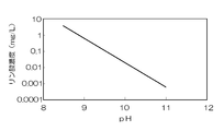
- the flow rate of the water supply pump 61 may be automatically controlled based on the measured value of the pH meter 63 based on the calibration curve of pH and phosphate ion concentration (phosphate concentration) shown in FIG.
- FIG. 12 is data obtained by experiments described in the examples described later, and shows the relationship between the phosphate ion concentration in the water to be treated and the pH of the water to be treated. From this figure, it can be seen that the phosphate ion concentration decreases as the pH increases.
- the water 93 to be treated is free of suspended solids in the sedimentation tank 52, specifically, small crystals of HAP that have flowed out without being able to stop at the drug loading unit 23, and thereafter , And sent to the pH adjustment tank 53.
- the treated water 93 sent to the pH adjusting tank 53 is alkaline and is neutralized with humic acid contained in the peat moss 55.
- the neutralized water 93 to be treated is discharged out of the system.
- fluorine When treating fluorine-containing wastewater, fluorine can be removed by the same treatment as phosphoric acid-containing wastewater by adding fluoroapatite or calcium fluoride as a seed crystal to the drug 32 instead of HAP.
- HAP may be added to the drug 32 as an adsorbent.
- boron can be removed by the same treatment as phosphoric acid-containing wastewater by adding calcium silicate hydrate as a seed crystal to the drug 32 instead of HAP. If necessary, a flocculant may be added. HAP may be added to the drug 32 as an adsorbent.
- medical agent 32 is seeded and adsorbed by performing the same process as phosphoric acid containing waste water. It acts as an agent and can simultaneously remove two or more of phosphoric acid, fluorine and boron.
- the reaction tank 51 using the multistage unit drug supply device 7 of the present invention can gradually elute the drug 32 into the water to be treated 93 by the multistage unit drug supply device 7, so that it can be continued for a long time.
- the pH adjustment tank 53 can be continuously used without performing maintenance as described above, and the waste water treatment facility 8 of the present invention can be continuously operated without performing maintenance for a long time as a whole.
- each drug loading unit 23 can be easily recovered, and each drug loading unit 23 is loaded with the drug 32 again. Can be used repeatedly.
- the collected HAP can also be reused.
- the elution amount of the drug 32 in the reaction tank 51 can be easily adjusted by the flow rate of the water to be treated 93, and the number of the multistage unit drug supply device 7 or the drug loading unit 23 of the multistage unit drug supply device 7 installed in series. It can also be adjusted by changing.
- FIG. 13 is a schematic configuration diagram of the waste water treatment facility 9 according to the ninth embodiment of the present invention.
- the wastewater treatment facility 9 of the ninth embodiment has the same basic configuration as the wastewater treatment facility 8 of the eighth embodiment, but includes a circulation line 64 that circulates the water to be treated 93 from the settling tank 52 to the reaction tank 51. .
- the waste water treatment facility 9 includes the circulation line 64, the water to be treated 93 can be repeatedly treated, and the concentration of the object to be treated contained in the water to be treated 93 can be further reduced.
- the circulation line 64 can also be provided in the treated water tank 57.
- the treated water 93 is phosphoric acid-containing wastewater, the higher the pH of the treated water 93, the easier the reaction proceeds. Is preferably returned to the reaction vessel 51.
- the particulate matter 35 when the particulate matter 35 is added to the water 93 to be treated, since the particulate matter 35 that has passed through the reaction tank 51 can be circulated and used, the amount of the particulate matter 35 added can be reduced.
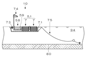
- FIG. 14 is a schematic configuration diagram of the wastewater treatment facility 10 according to the tenth embodiment of the present invention.
- FIG. 15 is a plan view of the waste water treatment facility 10 of FIG. The same components as those of the waste water treatment facility 8 of the eighth embodiment shown in FIG.
- the wastewater treatment facility 10 of the tenth embodiment is a floating wastewater treatment facility that can be installed in a lake or a dam lake.
- the wastewater treatment facility 10 includes a reaction tank 51, a pH adjustment tank 58, a casing 71 that accommodates the reaction tank 51 and the pH adjustment tank 58, a float 72 that floats the casing 71 in the water to be treated 94, and a reaction tank. 51, a water turbine 73 as supply means for supplying the water to be treated 94 to the water 51, a solar battery power generation device 74 for supplying driving power to the water turbine 73, and a fixing portion provided on the water bottom 80 to prevent drifting of the waste water treatment facility 10. And a mooring means 75 for mooring to the surface of the water to be treated.
- the pH adjustment tank 58 is filled with peat moss 59.
- peat moss 59 When the contained humic acid is used up, it is necessary to replace the peat moss 59. However, when the peat moss 59 is replaced, the consumption of the drugs loaded in the multistage drug supply device 7 is reduced. The frequency of maintenance can be reduced by setting the period to be the same period.
- the wastewater treatment facility 10 performs wastewater treatment in the reaction tank 51 that does not require maintenance for a long period of time and the pH adjustment tank 58, and since the driving power source of the water turbine 73 is the solar cell power generation device 74, it is installed in a lake or the like. Later, wastewater treatment can be continued without maintenance for a long period of time. Further, since the waste water treatment can be performed by natural flow without driving the water wheel 73, the waste water treatment can be performed without problems even in bad weather.
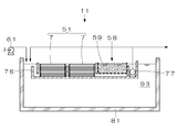
- FIG. 16 is a schematic configuration diagram of the waste water treatment facility 11 according to the eleventh embodiment of the present invention.
- the wastewater treatment facility 11 of the eleventh embodiment is a wastewater treatment facility installed in the wastewater storage tank 81.
- the wastewater treatment facility 11 includes a reaction tank 51, a pH adjustment tank 58, a casing 76 that houses the reaction tank 51 and the pH adjustment tank 58, and a submersible pump 77 for discharge and circulation. It is installed in the vicinity of the water surface and treats the water to be treated 93 in the drainage storage tank 81.
- the waste water treatment facility 11 of the present invention can be installed in the waste water storage tank 81, and, similarly to the waste water treatment facility of other embodiments, the waste water treatment can be continuously performed without performing long-term maintenance. it can.
- Such a wastewater treatment facility 11 can be used suitably for further treatment of wastewater after being treated with a normal wastewater treatment device, low-concentration contaminated water, etc., because it can treat wastewater over time. be able to. The same applies to the other wastewater treatment facilities 8, 9, and 10.
- Example 1 The test which removes the phosphoric acid of a phosphoric acid containing solution was implemented using the testing apparatus 100 using the serial cell chemical
- the flow path 102 of the serial cell drug supply device 101 has a width of 10 mm and a height of 3 mm.
- the drug loading unit 103 of the serial cell drug supply device 101 has a width of 10 mm, a length (opening) of 20 mm, and a depth of 15 mm, and ten drug loading units 103 are arranged in series.
- the drug 110 used was a mixture of calcium oxide containing 1% of HAP, which is a granular material 111, with water.
- the solution to be treated 115 is 300 mL of an aqueous solution having a phosphoric acid concentration of 50 mg / L. This was circulated by the circulation pump 104 at 20 mL / min, and 10 mL of a sample was taken after 0.5, 1, 2, 4, 8, and 24 hours, and the phosphoric acid concentration was measured.
- Example 2 Only the composition of the drug 120 was changed using the test apparatus 100 of Example 1, and the test was performed under the same conditions.
- medical agent 120 used what knead
- Example 2 As shown in FIG. 18, in both Example 1 and Example 2, the phosphoric acid concentration decreased with the lapse of the reaction time. Compared to Example 1, Example 2 has a slower rate of decrease in phosphoric acid concentration. This is presumably due to the addition of starch that limits the elution amount of calcium oxide (actually, it changes into calcium hydroxide by reacting with water), which is the main agent. For this reason, it is thought that the elution amount of the main agent can be adjusted by starch or the like.
Landscapes
- Chemical & Material Sciences (AREA)
- Health & Medical Sciences (AREA)
- Medicinal Chemistry (AREA)
- Life Sciences & Earth Sciences (AREA)
- Hydrology & Water Resources (AREA)
- Engineering & Computer Science (AREA)
- Environmental & Geological Engineering (AREA)
- Water Supply & Treatment (AREA)
- Organic Chemistry (AREA)
- Separation Of Suspended Particles By Flocculating Agents (AREA)
- Removal Of Specific Substances (AREA)
- Water Treatment By Sorption (AREA)
Abstract
撹拌機等の機器を用いることなく、コンパクトで効率的に薬剤を溶出させ供給することができる薬剤供給装置、該薬剤供給装置を用いたメンテナンスフリー又はメンテナンスが簡単な排水処理装置、及び排水処理設備を提供する。 液体90を流通させる流路21と、上面26に開口部27を備え、該開口部27を流路21に臨ませ該開口部27において流路21が急激に拡大するように設けられた薬剤装填部23と、を備え、液体90を流し開口部27において強制的に乱流95を生じさせ、該乱流95を利用し薬剤装填部23に装填された薬剤31を溶出させる。
Description
本発明は、液体に薬剤を溶出させる薬剤供給装置、該薬剤供給装置を用いた排水処理装置及び排水処理設備に関する。
湖水・ダムでは富栄養化、特にリン酸濃度が高くなりアオコが発生する事象がよく見られる。ダム湖等に流入する排水は、排水基準以下、一般排水基準では16mg/L(日間平均8mg/L)、暫定排水基準(畜産業)では30mg/L(日間平均248mg/L)に処理された水であるが、アオコの発生を抑制するためには、流入排水中のリン酸を1mg/L以下、ダム湖等においてリン酸を0.01mg/L以下にする必要がある。
排水など被処理水中のリン酸を除去する方法としては、被処理水中にカルシウム分を添加し、ハイドロオキシアパタイトを種晶としてリン酸を晶析させて除去する方法がある(例えば、特許文献1参照)。
さらに廃液中のリン分を除去する方法として、石膏等の難溶性カルシウム含有物を充填した充填槽に被処理水を通過させ、被処理水中にカルシウム分を継続的に溶出させることで薬剤の濃度管理及び補充のコストを低減させる技術もある(例えば、特許文献2参照)。
なお排水処理以外の分野においても薬剤を液体中に溶出させるニーズは多く、例えば、シャワーヘッドが接続された配管に薬剤が充填された着脱式の混入容器を接続し、湯の放出に伴い薬剤を徐々に溶出させる技術が提案されている(例えば、特許文献3参照)。
排水中のリン酸除去に限らず、一般的な排水処理装置では、反応槽の他、薬剤注入装置、計測、制御装置等が必要であり、排水処理装置が大掛りとなる。簡易な装置で安価に排水処理を行いたいとの要求は強く、排水基準内の水をさらに浄化するような場合にはなおさらである。
特許文献2、3に記載の発明のように、難溶性の薬剤を使用することで一定の割合で薬剤を溶出させることが可能となり、薬剤の濃度管理や補充が容易となるが、処理速度を増加させるには薬剤を効率的に溶出させる必要が生じる。このとき特許文献3に記載の発明のように薬剤の表面積を増大させる方法では装置が巨大化してしまう。
本発明の目的は、撹拌機等の機器を用いることなく、コンパクトで効率的に薬剤を溶出させ供給することができる薬剤供給装置、該薬剤供給装置を用いたメンテナンスフリー又はメンテナンスが簡単な排水処理装置、及び排水処理設備を提供することである。
本発明は、液体を流通させる流路と、上面に開口部を備え、該開口部を前記流路に臨ませ該開口部において流路が急激に拡大するように設けられた薬剤装填部と、を備え、液体を流し前記開口部において強制的に乱流を生じさせ、該乱流を利用し前記薬剤装填部に装填された薬剤を溶出させることを特徴とする薬剤供給装置である。
本発明によれば、薬剤装填部の開口部において流路を急激に拡大させ、液体を流し該開口部において強制的に乱流を生じさせ、この乱流を利用し薬剤装填部に装填された薬剤を溶出させるので薬剤の移送(供給)と撹拌とが一緒に行われ非常に効率的である。薬剤装填部の大きさを数mL~数百mL程度の大きさとすれば、少ない流量でも容易に乱流を生じさせることができる。ここで乱流とは、渦流など液に大きな乱れが生じた流動状態を言う。上記の通り本発明の薬剤供給装置は、薬剤を溶出するための撹拌機等を必要としないため装置をコンパクトにすることができる。
また本発明の薬剤供給装置は、前記薬剤装填部に装填する薬剤が、難溶性の固形薬剤であることを特徴とする。
本発明によれば、薬剤装填部に装填する薬剤が、難溶性の固形薬剤なので、液体中に薬剤を長期間に亘って徐々に溶出させることが可能であり、長期間継続しての使用が可能となる。
また本発明の薬剤供給装置は、前記開口部において乱流の発生を促進させる乱流発生促進手段を備えることを特徴とする。
また本発明の薬剤供給装置は、流路を流通する液体に圧力差を生じせしめ乱流を発生させることを特徴とする。
また本発明の薬剤供給装置は、前記乱流発生促進手段が、絞りであることを特徴とする。
本発明によれば、薬剤供給装置は、開口部において乱流の発生を促進させる乱流発生促進手段を備えるので、開口部において確実に乱流を発生させることができ、また乱流を増大させることが可能となり、薬剤をより効率的に溶出させることができる。
また本発明は、前記薬剤供給装置が、直列に複数配置され、配置する個数により薬剤の溶出量を調節することを特徴とする薬剤供給装置である。
本発明によれば、薬剤供給装置が、直列に複数配置され、配置する個数により薬剤の溶出量を調節するので、薬剤の溶出量の調節が容易であり、薬剤の溶出量を調節するための計測機器、制御機器等が不要である。
また本発明は、前記薬剤供給装置が、並列に複数配置されていることを特徴とする薬剤供給装置である。
本発明によれば、薬剤供給装置が、並列に複数配置されているので、薬剤の供給量を容易に増加させることができる。さらにこのような薬剤供給装置を、排水処理装置の薬剤供給装置兼反応槽として使用する場合、一つの流路で目詰まりが発生したとしても他の流路で排水処理を行うことが可能であり使い勝手がよい。
また本発明の薬剤供給装置は、前記薬剤装填部が、隙間なく配置されていることを特徴とする。
本発明によれば、前記薬剤装填部が、隙間なく配置されているので、装置をコンパクト化することができる。
また本発明は、前記薬剤供給装置が、多段に積層されていることを特徴とする薬剤供給装置である。
本発明によれば、薬剤供給装置が、多段に積層されているので、薬剤の供給量を容易に増加させることができる。供給量が増加しても薬剤溶出の斑が少なく、薬剤を効率よく溶出させることができるため装置をコンパクト化することができる。
また本発明の薬剤供給装置は、さらに前記流路に流す液体の流量を調節する流量調節手段を備え、該流量調節手段により流量を調節することで前記薬剤の溶出量を調節可能なことを特徴とする。
本発明によれば、流量調節手段により流量を調節することで薬剤の溶出量を調節することができるので、薬剤の溶出量の調節を容易に行うことができる。
また本発明の薬剤供給装置において、前記薬剤は、主剤の他、主剤の溶出量を調節する溶出量調節剤を含むことを特徴とする。
本発明によれば、薬剤は、主剤の他、主剤の溶出量を調節する溶出量調節剤を含むので、薬剤の徐放性をコントロール可能であり、メンテナンス期間をある程度自由に設定することができる。
また本発明の薬剤供給装置は、前記薬剤が粉粒状物を含み、前記薬剤が溶出することで前記粉粒状物が放出され、放出された前記粉粒状物が乱流の作用により前記薬剤の表面を侵食し、前記薬剤の溶出が促進されることを特徴とする。
本発明によれば、薬剤供給装置は、薬剤が粉粒状物を含み、薬剤が溶出することで粉粒状物が放出され、放出された粉粒状物が乱流の作用により薬剤の表面を侵食し、薬剤の溶出が促進されるので、より効率的に薬剤を溶出させることができる。
また本発明の薬剤供給装置において、放出された前記粉粒状物は、前記薬剤装填部に止まり、前記薬剤装填部から流出しないことを特徴とする。
本発明によれば、放出された粉粒状物は、薬剤装填部に止まり、薬剤装填部から流出しないので、薬剤が溶出し切るまで粉粒状物の効果を持続させることができる。
また本発明の薬剤供給装置は、流路を流れる液体が粉粒状物を保有し、該粉粒状物が乱流の作用により前記薬剤の表面を侵食し、前記薬剤の溶出が促進されることを特徴とする。
本発明によれば、流路を流れる液体が粉粒状物を保有し、該粉粒状物が乱流の作用により薬剤の表面を侵食し、薬剤の溶出が促進されるので、より効率的に薬剤を溶出させることができる。
また本発明は、前記薬剤供給装置を備え、前記薬剤供給装置に被処理物を除去するために必要な薬剤を装填し、前記薬剤供給装置に被処理水を供給し、被処理水中の被処理物に前記薬剤を作用させ該被処理物を除去することを特徴とする排水処理装置である。
また本発明の排水処理装置において、前記被処理物がリン酸、ホウ素、フッ素のうち、いずれか1種であり、前記薬剤が難水溶性カルシウム化合物を含み、前記被処理物と、前記難水溶性カルシウム化合物から溶出したカルシウム分と、を反応させ、不水溶性カルシウム化合物を生成させ、被処理水中の被処理物を除去することを特徴とする。
また本発明の排水処理装置において、前記排水処理装置は、さらに前記薬剤が、pH調整剤を含むことを特徴とする。
また本発明の排水処理装置において、前記被処理物がリン酸であり、前記不水溶性カルシウム化合物がハイドロオキシアパタイトであり、前記難水溶性カルシウム化合物とpH調整剤とが水酸化カルシウムであり、前記薬剤は、少なくとも酸化カルシウムと、ハイドロオキシアパタイトからなる種晶と、水とを混練し、これを前記薬剤装填部に装填後、固化させたものであることを特徴とする。
また本発明の排水処理装置において、前記薬剤は、前記混練時、さらに溶出量調節剤を加えることを特徴とする。
また本発明の排水処理装置において、前記溶出量調節剤は、石膏及び/又は澱粉であることを特徴とする。
また本発明の排水処理装置において、前記種晶及び種晶を核に成長させたハイドロオキシアパタイトは、前記薬剤装填部から流出しないことを特徴とする。
本発明によれば、薬剤供給装置は、排水処理装置の薬剤供給装置として、さらには薬剤供給装置兼反応槽として好適に使用可能である。特に被処理物がリン酸である場合、種晶及び種晶を核に成長させたハイドロオキシアパタイトが薬剤装填部から流出しないので、薬剤が溶出し切った後、ハイドロオキシアパタイトが薬剤装填部に残留しており回収が非常に容易である。
また本発明の排水処理装置において、前記被処理物がリン酸、ホウ素、フッ素のうち2種以上を含み、前記薬剤が難水溶性カルシウム化合物を含み、リン酸、ホウ素、フッ素のうち2種以上と、前記難水溶性カルシウム化合物から溶出したカルシウム分と、を反応させ、不水溶性カルシウム化合物を生成させ、被処理水中の被処理物を同時処理することを特徴とする。
また本発明の排水処理装置において、さらに凝集剤又は凝集剤と凝集助剤とを添加し、被処理水中の被処理物を除去することを特徴とする。
また本発明の排水処理装置において、さらに吸着剤を添加し、被処理水中の被処理物を除去することを特徴とする。
また本発明の排水処理装置において、さらに前記被処理物が除去された後の被処理水のpHを測定するpH計を備え、前記被処理物がリン酸であり、前記pH計で被処理水中のpHを測定し、被処理水中のリン酸濃度を算出することを特徴とする。
また本発明の排水処理装置は、前記pH計の測定値から算出したリン酸濃度を基に前記流量調節手段により前記薬剤供給装置に供給する被処理水の流量を調節することを特徴とする。
本発明によれば、pH計の測定値から算出したリン酸濃度を基に前記流量調節手段により流量を調節するので、被処理水中のリン酸濃度が所定の濃度になるように、比較的安価なpH計を用いて自動制御を行うことができる。
また本発明は、前記排水処理装置を備え、前記薬剤供給装置が反応槽を兼用し、さらに前記薬剤装填部で生成した反応生成物を沈殿分離する沈殿槽と、前記沈殿槽の下流側に設置され、中和剤により被処理水のpHを調整するpH調整槽と、を含むことを特徴とする排水処理装置である。
また本発明の排水処理装置は、前記中和剤が、フミン酸であり、前記pH調整槽に腐朽菌を保有するピートモスを充填し、該ピートモスに腐朽菌を作用させ前記フミン酸を生成させ、該ピートモスと被処理水とを接触させ、被処理水を前記フミン酸で中和しpHを調整することを特徴とする。
また本発明の排水処理装置は、前記被処理水を利用し、前記ピートモスを湿潤かつ好気状態とし、前記腐朽菌が良好に育成する高湿好気状態とする環境形成手段を備えることを特徴とする。
本発明によれば、排水処理装置は、反応槽に薬剤を長期間に亘って徐々に溶出可能な薬剤供給装置を用いており、pH調整槽に腐朽菌が良好に育成可能なピートモスを用いており、反応槽及びpH調整槽が長期間メンテナンスを行うことなく継続運転可能なので、装置全体としても長期間メンテナンスを行うことなく継続運転することが可能である。また本発明の排水処理装置は、反応槽及びpH調整槽に特別な撹拌機器や計測機器、制御機器等を必要としないので、コンパクトにすることができる。
また本発明の排水処理装置は、さらに前記沈殿槽から排出され前記pH調整槽に流入する前の被処理水の一部を、前記薬剤供給装置に返送する循環手段を備えることを特徴とする。
本発明によれば、沈殿槽から排出されpH調整槽に流入する前の被処理水の一部を、薬剤供給装置に返送する循環手段を備えるので、被処理物を十分に除去することができる。また粉粒状物を含有する液体を用いる場合、粉粒状物を循環して再利用することができるので、粉粒状物の使用量を低減させることができる。
また本発明は、前記排水処理装置と、前記排水処理装置を収容する筐体と、前記筐体を被処理水上に浮かべるフロートと、前記排水処理装置に被処理水を供給する供給手段と、を含むことを特徴とする排水処理設備である。
また本発明の排水処理設備において、前記供給手段は、水車又はポンプであり、前記水車又はポンプの駆動電源を供給する太陽電池発電装置を備えることを特徴とする。
また本発明の排水処理設備は、排水貯槽、湖沼又はダム湖に設置され、前記供給手段により移動可能なことを特徴とする。
本発明によれば、排水処理設備は、排水処理装置と、排水処理装置を収容する筐体と、筐体を被処理水上に浮かべるフロートと、排水処理装置に被処理水を供給する供給手段と、を含み、供給手段は、水車又はポンプであり、水車又はポンプの駆動電源を供給する太陽電池発電装置を備えるので、湖沼又はダム湖に設置した後は、長期間メンテナンスフリーで排水処理を継続して行うことができる。
本発明によれば、撹拌機等の機器を用いることなく、コンパクトで効率的に薬剤を溶出させ供給することができる薬剤供給装置を提供することができる。このような薬剤供給装置は、排水処理装置及び排水処理設備に好適に用いることができる。また薬剤供給装置、これを使用した排水処理装置及び排水処理設備は、長期間メンテナンスを行うことなく、又は簡単なメンテナンスだけで継続して運転することが可能なので湖沼又はダム湖の水の浄化等に好適に使用することができる。
本実施形態において、薬剤装填部が1つの薬剤装填部からなる薬剤供給装置をセル薬剤供給装置、セル薬剤供給装置が複数直列に配置された薬剤供給装置を直列セル薬剤供給装置、直列セル薬剤供給装置を複数配置した薬剤供給装置をユニット薬剤供給装置、ユニット薬剤供給装置を多段に積層してなる薬剤供給装置を多段ユニット薬剤供給装置と言う。
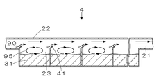
図1は、本発明の第1実施形態であるセル薬剤供給装置1の要部断面図である。セル薬剤供給装置1は、液体90を流通させる流路21と、薬剤31を装填する1つの薬剤装填部23とを備え、薬剤装填部23の上面26が流路21に臨む開口部27となっており、開口部27において強制的に乱流を生じさせ、この乱流を利用し薬剤装填部23に装填された薬剤31を溶出(溶解)させる。ここで乱流とは、液に大きな乱れが生じた流動状態を言い、渦流95が代表される。本発明においては、渦流95が形成される乱流状態が好ましく、以下、乱流を渦流95として説明する。
薬剤装填部23は、流路21に直交するように取付けられており、薬剤31は、薬剤装填部23の全深さ未満、つまり薬剤装填部23に対して上部に空間部が残るように充填される。このため薬剤装填部23において、断面積が前後の流路21の断面積に比較して急激に大きくなる。このような形状を有するセル薬剤供給装置1に液体90を流すと、薬剤装填部23において急激に流速が低下するため、薬剤装填部23の前後において液体に圧力差が生じ、図1に示すような流速分布96となり、薬剤31の表面付近での液体90の流れ方向が、流路21を流れる液体90の流れ方向とは反対方向になり、渦流95が発生する。
セル薬剤供給装置1の形状は、特定の形状に限定されるものではなく、用途に応じて適宜決めることができる。セル薬剤供給装置1の大きさを例示すれば、流路21の幅が数mm~数十mm程度、又は薬剤装填部23の容量が数mL~数百mL程度である。薬剤装填部23の深さは、渦流95が届く範囲とする。渦流95が届く範囲は、渦流95の大きさに影響され、渦流95の大きさは、流路21を流れる液体90の流速、開口部27の長さ、深さに依存する。
薬剤装填部23の深さを必要以上に深くすると、薬剤装填部23の上部では渦流95が形成されるものの、その渦流95が薬剤装填部23の下部まで届かなくなるので好ましくない。セル薬剤供給装置1は、液体90と接する薬剤31の表面において、液体90を積極的に流動させることで薬剤31を溶出させようとするものであるから、薬剤31の残量が少なくなった状態においても、薬剤31の表面に渦流95が直接接触するようにすることが重要である。
薬剤装填部23の長さは、渦流95が形成される長さとし、極端に長くすべきではない。さらには渦流95が薬剤31の表面において均一に形成されるように薬剤装填部23の全長を決めることが好ましい。
セル薬剤供給装置1の材質は、特定の材質に限定されるものではなく、流通する液体や装填する薬剤、使用環境等によって適宜決めることができる。
セル薬剤供給装置1は、流路21と薬剤装填部23とが着脱可能に構成(着脱式)されていてもよく、流路21と薬剤装填部23とが着脱不能に固定(一体型)されていてもよい。さらに天井部22を別体としてもよい(別体型)。
液体90は、特定のものに限定されるものではなく、用途に応じて適宜決めることができる。
薬剤31は、特定のものに限定されるものではなく、用途に応じて適宜決めることができるが、固形状で難溶性のものを用いると薬剤31の表面が液体90内に徐々に溶出し、長期間継続的に使用することができるので好ましい。特に本発明のセル薬剤供給装置1は、積極的に渦流95を発生させ、この渦流95を利用し薬剤装填部23に装填された薬剤31を溶出させるものであるから、固形状で難溶性の薬剤31の溶出に好適に使用することができる。渦流95は、拡散性能に優れることはもちろん、薬剤31の表面を浸食する作用も期待できるので、薬剤31の溶出速度を大きくすることができる。なお、難溶性の薬剤31は、微溶性の薬剤、遅溶性の薬剤と捉えることもできる。
また薬剤31に固形状のものを用いる場合は、継続的に使用可能なように、液体90の流れにより薬剤装填部23から流出しないように装填されていることが好ましい。
薬剤31の装填は、以下の要領で行うことができる。薬剤装填部23が着脱式の場合、薬剤装填部23に薬剤31を装填後、薬剤装填部23を流路21に取付ければよい。天井部22が別体型の場合、薬剤31を薬剤装填部23に装填した後に天井部22を取付ければよい。セル薬剤供給装置1が一体型の場合、流路21から薬剤31を流し込んでもよく、セル薬剤供給装置1の天井部22又は薬剤装填部23の底部から注入した後に注入孔(図示省略)を塞ぐような方法を採用することができる。
セル薬剤供給装置1に薬剤31を装填し、流路21を所定の速度で液体90を流通させると、薬剤装填部23の開口部27において渦流95が自然に発生し、薬剤31の液体90への溶解が促進される。ここで所定の速度とは、薬剤装填部23の開口部27において渦流95が発生する速度である。液体90に溶解した薬剤31は、下流側に運ばれるので、種々の用途に使用することができる。
以上のようにセル薬剤供給装置1は、供給する液体90の流れに強制的に乱れを生じさせ、その乱れを利用し薬剤を溶出(溶解)させるフローミキシングを利用した装置である。このようなセル薬剤供給装置1は、薬剤の溶出(溶解)能力に優れ、さらに薬剤31の移送(供給)と撹拌とが一緒に行われるので非常に効率的である。また薬剤31の溶出(溶解)に撹拌機等の機器を用いる必要がないので装置をコンパクトにすることができる。
またセル薬剤供給装置1は、液体90の流量が一定であれば薬剤31の溶出(溶解)量もほぼ一定に保たれるので、高価な計測機器等を用いることなく濃度管理を行うことができる。また薬剤31が溶出(溶解)し切るまではメンテナンスは不要であり、薬剤31が溶出(溶解)し切った後は、薬剤31を再度装填すれば繰返し使用することができるので使い勝手がよい。
セル薬剤供給装置1の用途は、特定の用途に限定されるものではなく、例えば、排水処理、水道水の改質、洗剤の溶解等、薬剤を液体に溶出(溶解)させる種々の用途に用いることができ、特に液体に薬剤を徐々に溶出(溶解)させるような用途に好適に用いることができる。薬剤の溶出(溶解)に着目すれば、セル薬剤供給装置1は、薬剤溶解装置とも言える。
図2は、本発明の第2実施形態であるセル薬剤供給装置2の要部断面図である。第1実施形態に示すセル薬剤供給装置1と同一の構成には、同一の符号を付して説明を省略する。第2実施形態のセル薬剤供給装置2は、第1実施形態のセル薬剤供給装置1と基本的構成は同じであるが、薬剤装填部23の開口部27において渦流95を発生させる渦流発生促進手段を備える。
図2(a)は、渦流発生促進手段として薬剤装填部23の上流側にフィン41が設けられたセル薬剤供給装置2を示す要部断面図である。フィン41は、平板状で開口部の上流側に設けられ、先端が下流側へ傾いた状態で流路21の一部を幅方向に亘って遮蔽するように設けられており、流路21を局所的に絞っている。フィン41は、セル薬剤供給装置2に一体的に形成されていてもよく、別途接着剤等で接着されていてもよい。
フィン41の角度、高さ及び厚みは、特定のものに限定されるものではなく、渦流95が薬剤31の表面において効果的に発生するように適宜決めることができる。またフィン41は、流路21の全幅に亘ってではなく、一部のみに設けられていてもよい。さらにフィン41の形状は、特定の形状に限定されるものではなく、例えば、V字状や波状等に湾曲した形状でもよい。フィン41の材質は、第1実施形態のセル薬剤供給装置1と同様、液体、薬剤、使用環境等に合わせて適宜決めることができる。
流路21又は薬剤装填部23内にフィン41を設けることで、フィン41の前後において圧力差を生じせしめ、薬剤装填部23の開口部27において積極的に渦流95を発生させ、薬剤31の液体90への溶出を促進することができる。以下に渦流発生促進手段の変形例を示す。以下に示す渦流発生促進手段のメカニズムは、図2(a)に示す渦流発生促進手段と同じである。
図2(b)は、渦流発生促進手段として薬剤装填部23の下流側にフィン41が設けられたセル薬剤供給装置2を示す要部断面図である。図2(c)は、渦流発生促進手段として薬剤装填部23の上流側における流路21の天井部22にフィン41が設けられたセル薬剤供給装置2を示す要部断面図である。このようにフィン41を設ける位置は、特定の位置に限定されるものではなく、渦流95が薬剤31の表面において効果的に発生するように適宜決めることができる。
図2(d)~図2(f)は、渦流発生促進手段として流路21の天井部22に流路21に直交する角度でフィン42がそれぞれ薬剤装填部23の上流側、中央、下流側に設けられたセル薬剤供給装置2を示す要部断面図である。このようにフィン42の取付け位置は、特定の位置に限定されるものではなく、渦流95が薬剤31の表面において効果的に発生するように適宜決めることができる。
図2(g)は、渦流発生促進手段として流路21の天井部22に凸部43が設けられたセル薬剤供給装置2を示す要部断面図である。凸部43は、薬剤装填部23の中央においてドーム状に形成されているが、これに限定されるものではなく、位置、形状、幅、高さ、材質等は、フィン41、42と同様、渦流95が薬剤31の表面において効果的に発生するように適宜決めることができる。
以上のように第2実施形態のセル薬剤供給装置2は、渦流発生促進手段により流路21を局所的に絞り、液体90に圧力差を生じせしめ薬剤装填部23の開口部27における渦流95の発生を促進させ、または渦流を増大させることで薬剤31の溶出を促進させることができる。なお複数の渦流発生促進手段を組合せて用いてもよい。
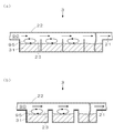
図3は、本発明の第3実施形態である直列セル薬剤供給装置3の要部断面図である。なお図3(a)は、各薬剤装填部23が隣り合う状態で直列配置された直列セル薬剤供給装置3を示す要部断面図であり、図3(b)は、各薬剤装填部23が距離を隔てた状態で直列配置された直列セル薬剤供給装置3を示す要部断面図である。第1実施形態に示すセル薬剤供給装置1と同一の構成には、同一の符号を付して説明を省略する。
第3実施形態の直列セル薬剤供給装置3は、薬剤装填部23が直列に複数配置されており、各薬剤装填部23に薬剤31が装填されている。各薬剤装填部23では、液体90の流通に伴い、渦流95が発生することで薬剤31の溶解が促進される。
第3実施形態の直列セル薬剤供給装置3では、基本的に直列配置される薬剤装填部23の個数に比例して液体90への薬剤31の溶出量が増える。このため薬剤装填部23の個数を変更することで、液体90への薬剤31の溶出量を容易に調節することができる。
各薬剤装填部23同士の距離は、特定の距離に限定されるものではないが、図3(a)に示すように、薬剤装填部23間に隙間がない場合、直列セル薬剤供給装置3の全長を短くすることができる。一方、図3(b)に示すように、薬剤装填部23間に距離を置いた状態で直列配置すると、全長が長くなるが、各薬剤装填部23において前後の薬剤装填部23での流れの影響を受け難く、各薬剤装填部23で流路21との圧力差を確保することができ、確実に渦流95を生じさせることができる。
また薬剤装填部23の大きさ及び開口部27の長さは、各薬剤装填部23で同一でなくてもよい。
図4は、本発明の第4実施形態である直列セル薬剤供給装置4の要部断面図である。第2実施形態に示すセル薬剤供給装置2と同一の構成には、同一の符号を付して説明を省略する。第4実施形態の直列セル薬剤供給装置4では、第2実施形態のセル薬剤供給装置2で用いたフィン41を有する状態で第3実施形態の直列セル薬剤供給装置3と同様に、薬剤装填部23が直列に複数配置されている。
このように渦流発生促進手段を有する直列セル薬剤供給装置4においても、薬剤装填部23を直列に複数配置することで、液体90への薬剤31の溶出量を容易に調節することができる。なお第4実施形態の直列セル薬剤供給装置4においても、各薬剤装填部23同士の距離、各薬剤装填部23の大きさ、開口部27の長さは、第3実施形態の直列セル薬剤供給装置3と同様の考え方で適宜決めることができる。
また第2実施形態のセル薬剤供給装置2と同様、渦流発生促進手段は、特定のものに限定されるものではなく、技術的に矛盾しない範囲で位置、形状、幅、高さ、材質等を適宜決めることができる。
図5は、粒状物35が添加された薬剤32を装填した第4実施形態の直列セル薬剤供給装置4を示す要部断面図である。本発明の薬剤供給装置では、粒状物35が添加された薬剤32を装填することで薬剤32をより効率的に溶出させることができる。
粒状物35が添加された薬剤32を薬剤装填部23に装填すると、薬剤32の溶出に伴い、粒状物35が放出され、放出された粒状物35が渦流95の作用により薬剤32の表面を侵食することで、薬剤32の溶出が促進される。つまり粒状物35は、研磨剤として作用する。
粒状物35は、特定のものに限定されるものではないが、不水溶性で固形状のものが好ましく、例えば、種晶、砂、鉄粉等を用途に応じて適宜選択して用いることができる。例えば、後述の排水処理のように被処理水に含まれる被処理物と薬剤32とを反応させ、晶析物を得るような場合には、晶析物の核となる種晶を用いればよい。単に薬剤32の溶出促進に使用するのであれば、後処理が簡単で安価な砂等を使用すればよい。
粒状物35の大きさ、形状、比重、添加量は、溶出速度に影響を与えるので、用途に応じて適宜選択して使用すればよい。なお粒状物35の大きさ及び/又は比重が小さいと液体90の流れとともに流路21へ流出する可能性が高まるので、例えば、粒状物35を種晶として用いる場合等には、液体90の流通時に薬剤装填部23に止まるような大きさ、比重のものを使用することが好ましい。
液体90の流通時に粒状物35が薬剤装填部23から流出される場合は、流出した粒状物35を循環させるようにしてもよい。但し、この場合にはポンプや配管等の摩耗に注意する必要がある。
このように直列セル薬剤供給装置4に装填する薬剤32に粒状物35を添加することで、薬剤32の溶出を容易に促進させることができる。
図6は、粒状物35が添加された液体91を流通させた第4実施形態の直列セル薬剤供給装置4を示す要部断面図である。本発明の薬剤供給装置では、粒状物35が添加された液体91を流通させることによっても、薬剤31の溶出を促進することができる。粒状物35は、上記の薬剤32に添加されたものと同様のものを用いることができる。
粒状物35が添加された液体91を流通させると、粒状物35が添加された薬剤32を用いたときと同様、粒状物35が渦流95の作用により薬剤31の表面を侵食することで、薬剤31の溶出が促進される。
液体91の流通時において粒状物35は、一部が入れ替わりながら薬剤装填部23に止まり、その他は液体91とともに流路21を流通する。これは、小さい粒状物35が添加された薬剤32を薬剤装填部23に装填したときとほぼ同じ挙動であり、この場合も粒状物35を循環させるようにしてもよい。
このように直列セル薬剤供給装置4に流通させる液体91に粒状物35を添加することでも、薬剤31の溶出速度を容易に高めることができる。なお、上記図5及び図6に示す直列セル薬剤供給装置4において、粒状物35に代えて粉状物を使用することも可能であり、粉状物を使用する場合も粒状物35を使用する場合と同様に考えることができる。
図7は、本発明の第5実施形態であるユニット薬剤供給装置5a、5bの概略構成図である。第4実施形態に示す直列セル薬剤供給装置4と同一の構成には、同一の符号を付して説明を省略する。第5実施形態のユニット薬剤供給装置5a、5bは、薬剤装填部23が直列及び並列に複数配置されている。
図7(a)に示すユニット薬剤供給装置5aは、第4実施形態の直列セル薬剤供給装置4が並列に複数配置されている。このためユニット薬剤供給装置5aは、液体、薬剤の供給量を容易に増加させることができるとともに、一部の流路21で目詰まりが発生したとしても他の流路21が引き続き液体を流通可能なので、容易にバックアップが可能である。なお並列に配置される各直列セル薬剤供給装置4同士は、それぞれが接着剤等で固定されていてもよく、一体的に製造されていてもよい。
図7(b)に示すユニット薬剤供給装置5bは、流路21に仕切が無い状態で薬剤装填部23が直列及び並列に複数配置されている。この場合、製造コストを抑えることができるが、ユニット薬剤供給装置5の容積が大きくなるにつれて流速に斑が生じ易くなり、薬剤の溶出量が不安定になり易い。また薬剤の消耗量が場所によって不均一となり易い。よって薬剤の溶出量を安定化させ、薬剤の消耗量を均一化させる場合には図7(a)に示すように、流路21に仕切がある方が好ましい。
なお薬剤装填部23の並べ方は、特定の並べ方に限定されるものではない。以下に薬剤装填部23を複数配置した実施例をいくつか示す。
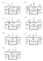
図8は、薬剤装填部23を複数配置するときの配置例を示す平面視における薬剤供給装置の断面図である。図8(a)で示すユニット薬剤供給装置では、薬剤装填部23が平面視において正方形であり、流れ方向に対して2辺が直交する向きで隙間なく配置されている。
図8(b)で示すユニット薬剤供給装置では、薬剤装填部23が平面視において正方形であり、流れ方向に対して各辺が45度傾いた向きで隙間なく配置されている。
図8(c)で示すユニット薬剤供給装置では、薬剤装填部24が平面視において円形であり、流れ方向に対して平行な方向及び直交する方向ともに各薬剤装填部24同士が整列するように配置されている。
図8(d)で示すユニット薬剤供給装置では、薬剤装填部24が平面視において円形であり、各薬剤装填部24同士の隙間が最小となるように配置されている。
図8(e)で示すユニット薬剤供給装置では、薬剤装填部25が平面視において正六角形であり、各薬剤装填部23が隙間なく配置されている。
このように薬剤装填部23、24、25の並べ方は、特定の並べ方に限定されるものではないが、各薬剤装填部23、24、25を隙間なく配置するとユニット薬剤供給装置をコンパクト化することができ、好ましい。
図9は、本発明の第6実施形態である多段ユニット薬剤供給装置6の斜視図である。図7に示す第5実施形態のユニット薬剤供給装置5aと同一の構成には、同一の符号を付して説明を省略する。第6実施形態の多段ユニット薬剤供給装置6は、第5実施形態のユニット薬剤供給装置5aが多段に配置されている。
多段ユニット薬剤供給装置6は、第5実施形態のユニット薬剤供給装置5aが多段に配置されており、液体、薬剤の供給量を容易に増加させることができるとともに、一部の流路21で目詰まりが発生したとしても他の流路21が引き続き液体を流通可能なので、容易にバックアップが可能となる。なお多段に配置されるユニット薬剤供給装置5aは、それぞれが接着剤等で固定されていてもよく、一体的に製造されていてもよい。
図10は、本発明の第7実施形態である多段ユニット薬剤供給装置7の斜視図である。第7実施形態の多段ユニット薬剤供給装置7は、薬剤の装填が容易なように、天井部のないユニット薬剤供給装置5cが多段に配置されている。
多段ユニット薬剤供給装置7は、天井部のないユニット薬剤供給装置5cと、ユニット薬剤供給装置5cを多段にスライドさせて収納可能な箱体45とを備え、ユニット薬剤供給装置5cをスライドさせて箱体45へ収納し、又は取り出すことができる。
ユニット薬剤供給装置5cは、第5実施形態のユニット薬剤供給装置5aの天井部を取り除いたものである。
箱体45は、幅及び奥行がユニット薬剤供給装置5cの幅及び全長と略同一で前面及び後面が開放された直方体であり、ユニット薬剤供給装置5cの高さと略同一の間隔で上面と平行に仕切46が設けられている。箱体45の高さは、ユニット薬剤供給装置5cを収納する段数によって決まり、ユニット薬剤供給装置5cの段数は、特定の段数に限定されるものではない。
また箱体45は、液体の流通時にユニット薬剤供給装置5cが動かないように固定手段(図示省略)を備える。固定手段は、種々の公知の固定手段を用いればよい。
多段ユニット薬剤供給装置7では、ユニット薬剤供給装置5cを箱体45から取り出して薬剤を装填することができるので、薬剤の装填が容易である。多段ユニット薬剤供給装置7は、特に、薬剤が溶出し切った後に再度ユニット薬剤供給装置5cに薬剤を装填して繰返し使用する場合に好適に用いることができる。
なお多段ユニット薬剤供給装置7では、ユニット薬剤供給装置5cの流路21の天井面は仕切46の下面となる。また仕切46は必ずしも設けなくてもよく、ユニット薬剤供給装置5cをそのまま多段積みにして仕切のない箱体(図示省略)へ収納するようにしてもよい。この場合は、ユニット薬剤供給装置5cの底面が流路21の天井面となる。また仕切46の代わりに、箱体45の両側にユニット薬剤供給装置5を支持する突起(図示省略)を設け、この突起によりユニット薬剤供給装置5cを支持し、ユニット薬剤供給装置5cの底面が流路21の天井面となるようにしてもよい。
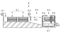
図11は、本発明の第8実施形態である排水処理設備8の概略構成図である。図10に示す第7実施形態の多段ユニット薬剤供給装置7と同一の構成には、同一の符号を付して説明を省略する。第8実施形態の排水処理設備8は、多段ユニット薬剤供給装置7を使用した排水処理設備である。
排水処理設備8は、被処理水93に含まれる被処理物(目的物)と薬剤とを反応させる反応槽51と、被処理水93中の固形分を沈降分離する沈殿槽52と、固形分を除去した後の被処理水93のpHを調整するpH調整槽53とを含み、反応槽51として第7実施形態の多段ユニット薬剤供給装置7が直列に2つ配置されている。また排水処理設備8は、被処理水93を供給するとともに、その流量を調節可能な給水ポンプ61と、反応槽51の出口部に設置され、被処理水93のpHを測定するpH計63とを備える。
反応槽51は、ユニット薬剤供給装置5cが多段に配置された第7実施形態の多段ユニット薬剤供給装置7であり、多段ユニット薬剤供給装置7の薬剤装填部23において反応が進行する。本実施形態では、2つの多段ユニット薬剤供給装置7で反応槽51を形成するが、多段ユニット薬剤供給装置7を長くして、1つの多段ユニット薬剤供給装置7で反応槽を形成してもよい。
また2つの多段ユニット薬剤供給装置7を直列に配置して使用する場合には、前段を反応槽、後段を凝集槽としてもよい。この場合には、後段の多段ユニット薬剤供給装置7に凝集剤を装填すればよい。さらに後段を凝集槽として使用する場合には、必要に応じて外部から後段の多段ユニット薬剤供給装置7に凝集助剤を添加するようにしてもよい。1つの多段ユニット薬剤供給装置7を反応槽及び凝集槽として使用する場合には、多段ユニット薬剤供給装置7の薬剤装填部23に装填する薬剤を前方(上流側)と後方(下流側)で変えればよい。
沈殿槽52は、一般的な排水処理設備における沈殿槽と同様に、反応槽51から排出される被処理水93に含まれる浮遊性固形分を沈降分離させる。
pH調整槽53は、槽内に中和剤を装填し、これに被処理水93が接触することでpHが調整される。アルカリを中和する場合は、腐朽菌を保有するピートモス55を充填したpH調整槽53を用いることができる。この方式の場合、腐朽菌の作用により中和剤として機能するフミン酸を継続的に生成することができるため、基本的にメンテナンスは不要である。フミン酸は、アルカリ性の溶液に溶解し易いのでアルカリ性溶液の中和剤として好ましい。また酸を中和する場合は、中和剤として、例えば、炭酸カルシウム(石灰砂、サンゴ砂等)を好適に用いることができる。なお一般的な排水処理設備で使用される外部から中和剤を添加する方法も採用することもできる。
腐朽菌を保有するピートモス55を充填したpH調整槽53を用いる場合は、ピートモス55を高湿好気状態とし、腐朽菌が良好に育成する状態を形成する必要がある。pH調整槽53に、ピートモス55を高湿好気状態に保つ環境形成手段としてサイホン56を設け、被処理水93が一定の高さに達すると処理水槽57へ流れ込み、ピートモス55が大気中に露出されるように構成することで、被処理水93の充填と排出とにより干満を繰返し、ピートモス55を常に湿潤かつ好気状態にすることができる。このようにするとpH調整槽53は、長期間メンテナンスを行うことなく継続して使用することができる。なおpH調整槽53で中和された被処理水93は、処理水槽57から系外へ放流される。
給水ポンプ61は、被処理水93の供給流量を調節可能であり、単独で、又はpH計63と連動して供給流量を調節することができる。これにより被処理水93への薬剤の溶出量を調節することができる。
以上のように、排水処理設備8は、外部からの薬剤供給の必要がない薬剤を自給する方式の排水処理設備であるので、機器構成が非常に簡素化され、制御系統も殆ど必要としない。このため安価に製造可能であり、保守点検も殆ど必要ない。
排水処理設備8で処理可能な被処理水93は、特定の被処理水に限定されるものではなく、例えば、リン酸含有排水、フッ素含有排水、ホウ素含有排水、又はこれらの複合排水等を処理することができる。排水以外に、廃液を処理可能なことは当然であるが、純水製造装置、さらには水溶液中の有価物を回収する装置としても使用することができる。よって本実施形態に示す排水処理設備8は、広く水処理設備と言うことができる。
以下、排水処理設備8を用いて、リン酸含有排水の処理例を示す。リン酸含有排水を被処理水93とする場合、多段ユニット薬剤供給装置7の薬剤装填部23に装填する薬剤としては、不水溶性の粒状物35を含み、固形状で難水溶性の薬剤32を用いる。薬剤32は、主剤であるカルシウム供給源のカルシウム化合物と、種晶(粒状物35)である不水溶性のハイドロオキシアパタイト(以下、HAPと記す)とを含む。カルシウム化合物とHAPは、必須であり、必要に応じてpH調整剤、主剤の溶出量を抑制する溶出量調節剤、水溶性成形剤等を添加することができる。
主剤であるカルシウム化合物には、水酸化カルシウム(消石灰)、酸化カルシウム(生石灰)を好適に用いることができる。この他、硫酸カルシウム(石膏)等をカルシウム化合物として使用することもできる。
pH調整剤としては、水酸化カルシウムを好適に使用することができる。水酸化カルシウムを用いた場合、水酸化カルシウムは、カルシウム供給源でありかつpH調整剤となる。
溶出量調節剤は、主剤の溶出量を抑制するための薬剤であり、主剤であるカルシウム化合物と一緒に使用することで、主剤の含有量(濃度)を相対的に低下させる。このような溶出量調節剤は、主剤、リン酸の除去プロセスに悪影響を与えず、さらに被処理水93に悪影響を与えないものが好ましい。このような溶出量調節剤としては、硫酸カルシウム(石膏)や澱粉、その混合物等が例示される。
リン酸含有排水の処理手順は以下の通りである。主剤である酸化カルシウムと種晶であるHAPとに水を加え、これを混練し、多段ユニット薬剤供給装置7の各薬剤装填部23に装填する。pH調整槽53には、腐朽菌を保有するピートモス55を充填する。
薬剤32を装填した多段ユニット薬剤供給装置7を所定の位置にセットし、被処理水93を供給する。被処理水93が供給されると薬剤装填部23において渦流95が発生し、薬剤32が徐々に溶出する。薬剤32が溶出すると、被処理水93中のカルシウムイオン濃度及び水酸化イオン濃度(pH)が上昇するとともに、薬剤32からHAPが放出される。粒状物35であるHAPが放出されると、渦流95の作用によりHAPが薬剤32の表面を侵食し、薬剤32の溶出が促進される。
薬剤32が溶出し、被処理水93中のカルシウムイオン濃度及びpHが十分に上昇すると被処理水93中のリン酸イオン、カルシウムイオン及び水酸化イオンが反応し、不水溶性のHAPとして晶析することで被処理水93中のリン酸イオンが除去される。このとき薬剤32から放出されたHAPが種晶となり、晶析が促進される。つまり薬剤32に元々含まれていたHAPは、薬剤32の溶出及びHAPの晶析を促進させる。
このとき給水ポンプ61の流量を調節すれば、被処理水93と薬剤32との接触時間及び渦流95の強度が調節され、薬剤32の溶出量を調節することができる。また図12に示すpHとリン酸イオン濃度(リン酸濃度)との検量線を元にpH計63の測定値により給水ポンプ61の流量を自動制御するようにしてもよい。図12は、後述の実施例に記載の実験により得られたデータであり、被処理水中のリン酸イオン濃度と被処理水のpHとの関係を示す。この図からpHが高くなるに従って、リン酸イオン濃度が低くなることが分かる。
被処理水93中のリン酸イオンの除去が進み、薬剤32が溶出し切ると、カルシウムイオン濃度及びpHが下がり晶析反応が停止する。pH計63によりpHが下がったことが確認されると被処理水93の供給を停止し、多段ユニット薬剤供給装置7からユニット薬剤供給装置5cを取り外し、回収する。回収後のユニット薬剤供給装置5cの各薬剤装填部23には、高純度のHAP結晶のみが残留しているので、これらを回収し、再度、薬剤32を装填すればユニット薬剤供給装置5cを繰返し使用することができる。
リン酸が除去された後の被処理水93は、沈殿槽52で浮遊性の固形分、具体的には、薬剤装填部23に止まることができず流出したHAPの小さな結晶が除去され、その後、pH調整槽53に送られる。pH調整槽53に送られる被処理水93は、アルカリ性であるのでピートモス55に含まるフミン酸で中和される。中和された被処理水93は系外へ排出される。
フッ素含有排水を処理する場合は、HAPに代えてフルオロアパタイトやフッ化カルシウムを種晶として薬剤32に添加することでリン酸含有排水と同様の処理でフッ素を除去することができる。またHAPは、吸着剤として薬剤32に添加されていてもよい。
ホウ素含有排水を処理する場合は、HAPに代えて珪酸カルシウム水和物を種晶として薬剤32に添加することでリン酸含有排水と同様の処理でホウ素を除去することができる。なお必要に応じて、凝集剤を添加してもよい。またHAPは、吸着剤として薬剤32に添加されていてもよい。
またリン酸、フッ素、ホウ素のうち、2種以上を含む被処理水を処理する場合は、リン酸含有排水と同様の処理を行うことで、薬剤32に添加されているHAPが種晶及び吸着剤として働き、リン酸、フッ素、ホウ素のうち2種以上を同時に除去することができる。
以上のように、本発明の多段ユニット薬剤供給装置7を用いた反応槽51は、多段ユニット薬剤供給装置7により薬剤32を被処理水93中に徐々に溶出させることができるので、長期間継続して使用することができる。またpH調整槽53についても上記の通りメンテナンスを行うことなく継続して使用可能であり、本発明の排水処理設備8は、全体として長期間メンテナンスを行うことなく継続運転することができる。
また反応槽51は、薬剤32が溶出し切った後には各薬剤装填部23に高純度のHAPのみが残留するので、容易に回収可能であり、再度、各薬剤装填部23に薬剤32を装填すれば繰返し使用することができる。また回収したHAPも再利用することが可能である。
さらに反応槽51での薬剤32の溶出量は、被処理水93の流量により容易に調節可能であり、また多段ユニット薬剤供給装置7又は多段ユニット薬剤供給装置7の薬剤装填部23の直列設置数を変えることでも調節可能である。
また被処理水93の処理量を増やすときには多段ユニット薬剤供給装置7の並列設置数又は段数を増やすことで容易に対応することができる。
図13は、本発明の第9実施形態である排水処理設備9の概略構成図である。図11に示す第8実施形態の排水処理設備8と同一の構成には、同一の符号を付して説明を省略する。第9実施形態の排水処理設備9は、第8実施形態の排水処理設備8と基本的構成は同じであるが、沈殿槽52から反応槽51へ被処理水93を循環させる循環ライン64を備える。
排水処理設備9は、循環ライン64を備えるので、被処理水93を繰返し処理可能であり、被処理水93中に含まれる被処理物の濃度をさらに低減することができる。循環ライン64は、処理水槽57に設けることも可能であるが、被処理水93がリン酸含有排水の場合、被処理水93のpHが高い程、反応が進み易いのでpH調整槽53の前から反応槽51へ返送することが好ましい。
また被処理水93中に粒状物35を添加する場合、反応槽51を通過した粒状物35を循環して使用可能なので、粒状物35の添加量を低減することができる。
図14は、本発明の第10実施形態である排水処理設備10の概略構成図である。図15は、図14の排水処理設備10の平面図である。図11に示す第8実施形態の排水処理設備8と同一の構成には、同一の符号を付して説明を省略する。第10実施形態の排水処理設備10は、湖沼やダム湖等に設置可能な浮遊型の排水処理設備である。
排水処理設備10は、反応槽51と、pH調整槽58と、反応槽51及びpH調整槽58を収容する筐体71と、筐体71を被処理水94中に浮かべるフロート72と、反応槽51に被処理水94を供給する供給手段としての水車73と、水車73の駆動電源を供給する太陽電池発電装置74と、排水処理設備10の漂流を防止すべく水底80に設けられた固定部に係留する係留手段75とを備え、被処理水94上を浮遊し、被処理水94の排水処理を行う。
pH調整槽58には、ピートモス59が充填されており、含有するフミン酸を使い切るとピートモス59を交換する必要があるが、ピートモス59の交換時期と多段ユニット薬剤供給装置7に装填する薬剤の消耗期間とが同時期になるように設定することでメンテナンスの頻度を少なくすることができる。
排水処理設備10の排水処理方法は、第8実施形態の排水処理設備8と同様であるため説明を省略する。
排水処理設備10は、長期間メンテナンスが不要である反応槽51と、pH調整槽58とで排水処理を行い、また水車73の駆動電源が太陽電池発電装置74であるので、湖沼等に設置した後には長期間メンテナンスを行うことなく継続して排水処理を行うことができる。また水車73が駆動せずとも自然流により排水処理を行うことができるので悪天候時にも問題なく排水処理を行うことができる。
図16は、本発明の第11実施形態である排水処理設備11の概略構成図である。図14に示す第10実施形態の排水処理設備10と同一の構成には、同一の符号を付して説明を省略する。第11実施形態の排水処理設備11は、排水貯槽81に設置される排水処理設備である。
排水処理設備11は、反応槽51と、pH調整槽58と、反応槽51及びpH調整槽58を収容する筐体76と、放流用兼循環用の水中ポンプ77とを備え、排水貯槽81の水面付近に設置され、排水貯槽81内の被処理水93の処理を行う。
排水処理設備11の排水処理方法は、第8実施形態の排水処理設備8と同様であるため説明を省略する。
このように本発明の排水処理設備11は、排水貯槽81内に設置することもでき、他の実施形態の排水処理設備と同様、長期間メンテナンスを行うことなく継続して排水処理を行うことができる。このような排水処理設備11は、時間をかけて排水を処理することができるので通常の排水処理装置で処理された後の排水、濃度の低い汚染水等をさらに処理する場合に好適に使用することができる。他の排水処理設備8、9、10も同様である。
図面を参照しながら好適な薬剤供給装置、排水処理装置及び排水処理設備について説明したが、当業者であれば、本件明細書を見て、自明な範囲内で種々の変更および修正を容易に想定するであろう。従って、そのような変更及び修正は、請求の範囲から定まる発明の範囲内のものと解釈される。
<実施例1>
図17に示す直列セル薬剤供給装置101を用いた試験装置100を用いてリン酸含有溶液のリン酸を除去する試験を実施した。直列セル薬剤供給装置101の流路102は、幅10mm、高さ3mmである。また直列セル薬剤供給装置101の薬剤装填部103は、幅10mm、長さ(開口部)20mm、深さ15mmであり、薬剤装填部103が10個直列に並んでいる。
図17に示す直列セル薬剤供給装置101を用いた試験装置100を用いてリン酸含有溶液のリン酸を除去する試験を実施した。直列セル薬剤供給装置101の流路102は、幅10mm、高さ3mmである。また直列セル薬剤供給装置101の薬剤装填部103は、幅10mm、長さ(開口部)20mm、深さ15mmであり、薬剤装填部103が10個直列に並んでいる。
薬剤110は、粒状物111であるHAPを1%含む酸化カルシウムを水と混練したものを使用した。
被処理溶液115は、リン酸濃度50mg/Lの水溶液300mLである。これを循環ポンプ104により20mL/minで循環させ、0.5、1、2、4、8、24時間後にサンプルを10mL採取し、リン酸濃度を測定した。
<実施例2>
実施例1の試験装置100を用いて薬剤120の組成のみを変更し、同条件のもと試験を行った。薬剤120は、HAPを1%、澱粉を1%含む酸化カルシウムを水と混練したものを使用した。結果を図18に示す。
実施例1の試験装置100を用いて薬剤120の組成のみを変更し、同条件のもと試験を行った。薬剤120は、HAPを1%、澱粉を1%含む酸化カルシウムを水と混練したものを使用した。結果を図18に示す。
図18に示すように実施例1及び実施例2の両方において、反応時間の経過とともにリン酸濃度が低下した。また実施例1に比べ実施例2の方がリン酸濃度の低下速度が遅い。これは澱粉の添加により、主剤である酸化カルシウム(実際には水と反応し水酸化カルシウムに変化)の溶出量が制限されたことによるものと推察される。このため澱粉等により主剤の溶出量を調節することができると考えられる。
1、2 セル薬剤供給装置
3、4、101 直列セル薬剤供給装置
5a、5b、5c ユニット薬剤供給装置
6、7 多段ユニット薬剤供給装置
8、9、10、11 排水処理設備
21、102 流路
23、24、25、103 薬剤装填部
26 (薬剤装填部)上面
27 開口部
31、32、110、120 薬剤
35、111 粒状物
41、42 フィン
43 凸部
51 反応槽
52 沈殿槽
53 pH調整槽
55 ピートモス
56 サイホン
61 給水ポンプ
63 pH計
64 循環ライン
71、76 筐体
72 フロート
73 水車
74 太陽電池発電装置
77 水中ポンプ
81 排水貯槽
90、91 液体
93、94 被処理水
95 渦流
104 循環ポンプ
115 被処理溶液
3、4、101 直列セル薬剤供給装置
5a、5b、5c ユニット薬剤供給装置
6、7 多段ユニット薬剤供給装置
8、9、10、11 排水処理設備
21、102 流路
23、24、25、103 薬剤装填部
26 (薬剤装填部)上面
27 開口部
31、32、110、120 薬剤
35、111 粒状物
41、42 フィン
43 凸部
51 反応槽
52 沈殿槽
53 pH調整槽
55 ピートモス
56 サイホン
61 給水ポンプ
63 pH計
64 循環ライン
71、76 筐体
72 フロート
73 水車
74 太陽電池発電装置
77 水中ポンプ
81 排水貯槽
90、91 液体
93、94 被処理水
95 渦流
104 循環ポンプ
115 被処理溶液
Claims (33)
- 液体を流通させる流路と、
上面に開口部を備え、該開口部を前記流路に臨ませ該開口部において流路が急激に拡大するように設けられた薬剤装填部と、を備え、
液体を流し前記開口部において強制的に乱流を生じさせ、該乱流を利用し前記薬剤装填部に装填された薬剤を溶出させることを特徴とする薬剤供給装置。 - 前記薬剤装填部に装填する薬剤が、難溶性の固形薬剤であることを特徴とする請求項1に記載の薬剤供給装置。
- 前記開口部において乱流の発生を促進させる乱流発生促進手段を備えることを特徴とする請求項1又は2に記載の薬剤供給装置。
- 前記乱流発生促進手段は、流路を流通する液体に圧力差を生じせしめ乱流を発生させることを特徴とする請求項3に記載の薬剤供給装置。
- 前記乱流発生促進手段が、絞りであることを特徴とする請求項4に記載の薬剤供給装置。
- 請求項1から5のいずれか1項に記載の薬剤供給装置が、直列に複数配置され、配置する個数により薬剤の溶出量を調節することを特徴とする薬剤供給装置。
- 請求項1から6のいずれか1項に記載の薬剤供給装置が、並列に複数配置されていることを特徴とする薬剤供給装置。
- 前記薬剤装填部が、隙間なく配置されていることを特徴とする請求項6又は7に記載の薬剤供給装置。
- 請求項1から8のいずれか1項に記載の薬剤供給装置が、多段に積層されていることを特徴とする薬剤供給装置。
- さらに前記流路に流す液体の流量を調節する流量調節手段を備え、該流量調節手段により流量を調節することで前記薬剤の溶出量を調節可能なことを特徴とする請求項1から9のいずれか1項に記載の薬剤供給装置。
- 前記薬剤は、主剤の他、主剤の溶出量を調節する溶出量調節剤を含むことを特徴とする請求項1から10のいずれか1項に記載の薬剤供給装置。
- 前記薬剤が粉粒状物を含み、前記薬剤が溶出することで前記粉粒状物が放出され、放出された前記粉粒状物が乱流の作用により前記薬剤の表面を侵食し、前記薬剤の溶出が促進されることを特徴とする請求項1から11のいずれか1項に記載の薬剤供給装置。
- 放出された前記粉粒状物は、前記薬剤装填部に止まり、前記薬剤装填部から流出しないことを特徴とする請求項12に記載の薬剤供給装置。
- 流路を流れる液体が粉粒状物を保有し、該粉粒状物が乱流の作用により前記薬剤の表面を侵食し、前記薬剤の溶出が促進されることを特徴とする請求項1から13のいずれか1項に記載の薬剤供給装置。
- 請求項1から14のいずれか1項に記載の薬剤供給装置を備え、前記薬剤供給装置に被処理物を除去するために必要な薬剤を装填し、前記薬剤供給装置に被処理水を供給し、被処理水中の被処理物に前記薬剤を作用させ該被処理物を除去することを特徴とする排水処理装置。
- 前記被処理物がリン酸、ホウ素、フッ素のうち、いずれか1種であり、前記薬剤が難水溶性カルシウム化合物を含み、
前記被処理物と、前記難水溶性カルシウム化合物から溶出したカルシウム分と、を反応させ、不水溶性カルシウム化合物を生成させ、被処理水中の被処理物を除去することを特徴とする請求項15に記載の排水処理装置。 - さらに前記薬剤が、pH調整剤を含むことを特徴とする請求項16に記載の排水処理装置。
- 前記被処理物がリン酸であり、前記不水溶性カルシウム化合物がハイドロオキシアパタイトであり、
前記難水溶性カルシウム化合物と前記pH調整剤とが水酸化カルシウムであり、
前記薬剤は、少なくとも酸化カルシウムと、ハイドロオキシアパタイトからなる種晶と、水とを混練し、これを前記薬剤装填部に装填後、固化させたものであることを特徴とする請求項17に記載の排水処理装置。 - 前記薬剤は、前記混練時、さらに溶出量調節剤を加えることを特徴とする請求項18に記載の排水処理装置。
- 前記溶出量調節剤は、石膏及び/又は澱粉であることを特徴とする請求項19に記載の排水処理装置。
- 前記種晶及び種晶を核に成長させたハイドロオキシアパタイトは、前記薬剤装填部から流出しないことを特徴とする請求項18から20のいずれか1項に記載の排水処理装置。
- 前記被処理物がリン酸、ホウ素、フッ素のうち2種以上を含み、前記薬剤が難水溶性カルシウム化合物を含み、リン酸、ホウ素、フッ素のうち2種以上と、前記難水溶性カルシウム化合物から溶出したカルシウム分と、を反応させ、不水溶性カルシウム化合物を生成させ、被処理水中の被処理物を同時処理することを特徴とする請求項15に記載の排水処理装置。
- さらに凝集剤又は凝集剤と凝集助剤とを添加し、被処理水中の被処理物を除去することを特徴とする請求項16から22のいずれか1項に記載の排水処理装置。
- さらに吸着剤を添加し、被処理水中の被処理物を除去することを特徴とする請求項16から23のいずれか1項に記載の排水処理装置。
- さらに前記被処理物が除去された後の被処理水のpHを測定するpH計を備え、
前記被処理物がリン酸であり、前記pH計で被処理水中のpHを測定し、被処理水中のリン酸濃度を算出することを特徴とする請求項16から24のいずれか1項に記載の排水処理装置。 - 前記pH計の測定値から算出したリン酸濃度を基に前記流量調節手段により前記薬剤供給装置に供給する被処理水の流量を調節することを特徴とする請求項25に記載の排水処理装置。
- 請求項15から26のいずれか1項に記載の排水処理装置を備え、前記薬剤供給装置が反応槽を兼用し、
さらに前記薬剤装填部で生成した反応生成物を沈殿分離する沈殿槽と、
前記沈殿槽の下流側に設置され、中和剤により被処理水のpHを調整するpH調整槽と、
を含むことを特徴とする排水処理装置。 - 前記中和剤が、フミン酸であり、
前記pH調整槽に腐朽菌を保有するピートモスを充填し、該ピートモスに腐朽菌を作用させ前記フミン酸を生成させ、該ピートモスと被処理水とを接触させ、被処理水を前記フミン酸で中和しpHを調整することを特徴とする請求項27に記載の排水処理装置。 - 前記被処理水を利用し、前記ピートモスを湿潤かつ好気状態とし、前記腐朽菌が良好に育成する高湿好気状態とする環境形成手段を備えることを特徴とする請求項28に記載の排水処理装置。
- さらに前記沈殿槽から排出され前記pH調整槽に流入する前の被処理水の一部を、前記薬剤供給装置に返送する循環手段を備えることを特徴とする請求項27から29のいずれか1項に記載の排水処理装置。
- 請求項15から30のいずれか1項に記載の排水処理装置と、
前記排水処理装置を収容する筐体と、
前記筐体を被処理水上に浮かべるフロートと、
前記排水処理装置に被処理水を供給する供給手段と、
を含むことを特徴とする排水処理設備。 - 前記供給手段は、水車又はポンプであり、
さらに前記水車又はポンプの駆動電源を供給する太陽電池発電装置を備えることを特徴とする請求項31に記載の排水処理設備。 - 排水貯槽、湖沼又はダム湖に設置され、前記供給手段により移動可能なことを特徴とする請求項31又は32に記載の排水処理設備。
Priority Applications (2)
| Application Number | Priority Date | Filing Date | Title |
|---|---|---|---|
| JP2015513539A JP5788628B2 (ja) | 2013-08-19 | 2013-08-19 | 薬剤供給装置、該薬剤供給装置を用いた排水処理装置及び排水処理設備 |
| PCT/JP2013/072098 WO2015025352A1 (ja) | 2013-08-19 | 2013-08-19 | 薬剤供給装置、該薬剤供給装置を用いた排水処理装置及び排水処理設備 |
Applications Claiming Priority (1)
| Application Number | Priority Date | Filing Date | Title |
|---|---|---|---|
| PCT/JP2013/072098 WO2015025352A1 (ja) | 2013-08-19 | 2013-08-19 | 薬剤供給装置、該薬剤供給装置を用いた排水処理装置及び排水処理設備 |
Publications (1)
| Publication Number | Publication Date |
|---|---|
| WO2015025352A1 true WO2015025352A1 (ja) | 2015-02-26 |
Family
ID=52483165
Family Applications (1)
| Application Number | Title | Priority Date | Filing Date |
|---|---|---|---|
| PCT/JP2013/072098 Ceased WO2015025352A1 (ja) | 2013-08-19 | 2013-08-19 | 薬剤供給装置、該薬剤供給装置を用いた排水処理装置及び排水処理設備 |
Country Status (2)
| Country | Link |
|---|---|
| JP (1) | JP5788628B2 (ja) |
| WO (1) | WO2015025352A1 (ja) |
Cited By (1)
| Publication number | Priority date | Publication date | Assignee | Title |
|---|---|---|---|---|
| WO2017095315A1 (en) * | 2015-12-02 | 2017-06-08 | Swedish Hydro Solutions Ab | A stormwater treatment apparatus, method and system |
Citations (5)
| Publication number | Priority date | Publication date | Assignee | Title |
|---|---|---|---|---|
| JPS60211266A (ja) * | 1984-04-02 | 1985-10-23 | Matsushita Electric Ind Co Ltd | 水処理容器 |
| JP2003285047A (ja) * | 2002-03-27 | 2003-10-07 | Toto Ltd | 徐放装置 |
| JP2004532106A (ja) * | 2001-02-12 | 2004-10-21 | ドーバー ケミカル コーポレイション | 制御された放出添加剤組成物 |
| JP2006167631A (ja) * | 2004-12-16 | 2006-06-29 | Kurita Water Ind Ltd | リン酸を含むフッ素含有排水の処理方法及び処理装置 |
| JP2011083657A (ja) * | 2009-10-13 | 2011-04-28 | Ebara Engineering Service Co Ltd | リン含有廃水の処理装置 |
Family Cites Families (1)
| Publication number | Priority date | Publication date | Assignee | Title |
|---|---|---|---|---|
| US8728405B2 (en) * | 2011-11-01 | 2014-05-20 | John B. Brandreth, III | Chemical dispenser assembly |
-
2013
- 2013-08-19 JP JP2015513539A patent/JP5788628B2/ja active Active
- 2013-08-19 WO PCT/JP2013/072098 patent/WO2015025352A1/ja not_active Ceased
Patent Citations (5)
| Publication number | Priority date | Publication date | Assignee | Title |
|---|---|---|---|---|
| JPS60211266A (ja) * | 1984-04-02 | 1985-10-23 | Matsushita Electric Ind Co Ltd | 水処理容器 |
| JP2004532106A (ja) * | 2001-02-12 | 2004-10-21 | ドーバー ケミカル コーポレイション | 制御された放出添加剤組成物 |
| JP2003285047A (ja) * | 2002-03-27 | 2003-10-07 | Toto Ltd | 徐放装置 |
| JP2006167631A (ja) * | 2004-12-16 | 2006-06-29 | Kurita Water Ind Ltd | リン酸を含むフッ素含有排水の処理方法及び処理装置 |
| JP2011083657A (ja) * | 2009-10-13 | 2011-04-28 | Ebara Engineering Service Co Ltd | リン含有廃水の処理装置 |
Cited By (1)
| Publication number | Priority date | Publication date | Assignee | Title |
|---|---|---|---|---|
| WO2017095315A1 (en) * | 2015-12-02 | 2017-06-08 | Swedish Hydro Solutions Ab | A stormwater treatment apparatus, method and system |
Also Published As
| Publication number | Publication date |
|---|---|
| JPWO2015025352A1 (ja) | 2017-03-02 |
| JP5788628B2 (ja) | 2015-10-07 |
Similar Documents
| Publication | Publication Date | Title |
|---|---|---|
| EP2683659B1 (en) | Reactor for precipitating solutes from wastewater and associated methods | |
| TW201708126A (zh) | 好氧性顆粒之形成方法、好氧性顆粒之形成裝置、排水處理方法及排水處理裝置 | |
| CN103328393A (zh) | 废液处理设备和废液处理方法 | |
| JPH1190483A (ja) | 排水処理方法および排水処理装置 | |
| JP4519485B2 (ja) | リンの回収方法及び装置 | |
| Luu et al. | Fluidized–bed homogeneous granulation for potassium and phosphorus recovery: K-struvite release kinetics and economic analysis | |
| CN203922907U (zh) | 一种景观水体外置除磷灭藻净化处理装置 | |
| JP5788628B2 (ja) | 薬剤供給装置、該薬剤供給装置を用いた排水処理装置及び排水処理設備 | |
| JP6935653B2 (ja) | 脱窒用硫黄資材 | |
| JP4647640B2 (ja) | 晶析反応装置及び晶析反応方法 | |
| JP5414169B2 (ja) | 晶析反応装置及び晶析反応方法 | |
| JP6173205B2 (ja) | 生物処理装置及び生物処理方法 | |
| Adnan | Pilot-scale study of phosphorus recovery through struvite crystallization | |
| JP5927216B2 (ja) | リン含有水のリン回収装置 | |
| JP5650164B2 (ja) | 晶析反応装置および晶析反応方法 | |
| JP2006281177A (ja) | 固形リン除去剤、リン除去剤供給装置及びそれを備える小規模排水浄化槽 | |
| TWI646059B (zh) | 排放水處理方法及排放水處理裝置 | |
| JP5222596B2 (ja) | 晶析反応装置 | |
| KR101787308B1 (ko) | 인 함유수의 인 회수장치 | |
| KR100761455B1 (ko) | 캐비테이션을 이용한 수중의 칼사이트 성장촉진, 및 이를활용한 수중의 고효율 칼슘제거 방법 및 장치 | |
| CN111792759A (zh) | 一种基于碳源回用的污水污泥调理工艺及系统 | |
| WO2004024637A1 (en) | Apparatus and method for removing phosphorus from waste lagoon effluent | |
| CN113443692A (zh) | 用于通过淘洗从废水中回收尺寸选定营养物的方法和设备 | |
| KR101793809B1 (ko) | 정석 반응장치 | |
| CN206232466U (zh) | 两级多相芬顿流化床系统 |
Legal Events
| Date | Code | Title | Description |
|---|---|---|---|
| ENP | Entry into the national phase |
Ref document number: 2015513539 Country of ref document: JP Kind code of ref document: A |
|
| 121 | Ep: the epo has been informed by wipo that ep was designated in this application |
Ref document number: 13891890 Country of ref document: EP Kind code of ref document: A1 |
|
| NENP | Non-entry into the national phase |
Ref country code: DE |
|
| 122 | Ep: pct application non-entry in european phase |
Ref document number: 13891890 Country of ref document: EP Kind code of ref document: A1 |