WO2015019475A1 - Vending machine the present invention pertains to a vending machine equipped with an inner door corresponding to a product sample compartment formed within an outer door. - Google Patents
Vending machine the present invention pertains to a vending machine equipped with an inner door corresponding to a product sample compartment formed within an outer door. Download PDFInfo
- Publication number
- WO2015019475A1 WO2015019475A1 PCT/JP2013/071563 JP2013071563W WO2015019475A1 WO 2015019475 A1 WO2015019475 A1 WO 2015019475A1 JP 2013071563 W JP2013071563 W JP 2013071563W WO 2015019475 A1 WO2015019475 A1 WO 2015019475A1
- Authority
- WO
- WIPO (PCT)
- Prior art keywords
- product sample
- mounting plate
- insulating material
- heat insulating
- vending machine
- Prior art date
Links
Images


Classifications
-
- G—PHYSICS
- G07—CHECKING-DEVICES
- G07F—COIN-FREED OR LIKE APPARATUS
- G07F9/00—Details other than those peculiar to special kinds or types of apparatus
- G07F9/10—Casings or parts thereof, e.g. with means for heating or cooling
Definitions
- the present invention relates to a vending machine provided with an inner door corresponding to a product sample chamber configured in an outer door.
- a product sample chamber is formed above the outer door that closes the front surface of the main body, and samples of products to be sold are displayed in the product sample chamber.
- an upper inner door for closing the product storage portion in the main body is provided, and the upper inner door can be opened and closed integrally with the outer door.
- this upper side inner door constitutes the back of the product sample chamber, and is provided on the rear side of the product sample mounting plate in which members such as a product sample holder and a lighting device for holding the product sample are attached to the front surface. It is composed of heat insulating material. And it was made possible to open and close backward independently of the outer door in the state where the outer door was opened, and the product sample could be exchanged in the state opened rearward from the outer door (for example, see Patent Document 1). )
- the product sample mounting plate is made of a coated steel plate made of a thin sheet metal, and a simple plate-like heat insulating material such as foamed polyurethane has been used as the heat insulating material.
- a structure for attaching a member such as a product sample holder or a lighting device (a special fixture such as a product sample holder and an integrally formed nail or screw) escapes.
- a lighting device a special fixture such as a product sample holder and an integrally formed nail or screw
- the present invention has been made in order to solve the conventional technical problem, and it is possible to reduce the cost by simplifying the structure while maintaining or improving the heat insulating performance of the inner door.
- the object is to provide a vending machine with improved stability.
- the vending machine of the present invention includes an outer door that closes the front opening of the main body so as to be freely opened and closed, a product sample chamber configured in the outer door, and a product storage configured in the main body. And a product sample mounting plate that is provided corresponding to the product sample chamber and that closes the front opening of the product storage portion so that it can be opened and closed. And a heat insulating material provided on the rear side of the product sample mounting plate with a space therebetween, and a protrusion that partially contacts the rear surface of the product sample mounting plate on the front surface of the heat insulating material. It is formed integrally.
- the vending machine according to a second aspect of the present invention is characterized in that, in the above invention, the front end of the protrusion is in line contact or point contact with the rear surface of the product sample mounting plate.
- the vending machine of the invention of claim 3 is characterized in that no protrusion is formed in a portion corresponding to a range in which the member is assumed to be attached to the front surface of the product sample mounting plate in each of the above inventions. .
- the vending machine of the invention of claim 4 causes the condensed water that grows on the rear surface of the product sample mounting plate to flow down on the front surface of the heat insulating material in each of the above inventions, with a space behind the product sample mounting plate.
- the drainage groove is integrally formed over the top and bottom.
- the vending machine of the invention of claim 5 is characterized in that, in the above invention, the front surface of the heat insulating material including the drainage groove is provided with open-cell packing that abuts against the rear surface of the product sample mounting plate. It is characterized by.
- a wiring storage portion for storing wiring is integrally formed on the front surface of the heat insulating material with a space behind the product sample mounting plate. It is characterized by.
- the vending machine of the invention of claim 7 includes an inner door mounting plate for mounting the product sample mounting plate on the heat insulating material in addition to the above, or in addition to the inner door mounting plate for mounting the inner door on the outer door.
- the board is embedded in the heat insulating material by insert molding.
- the vending machine of the invention of claim 8 is provided with a cover provided on the lower side of the heat insulating material in the above invention and formed with a drain receiver for receiving dew condensation water from the product sample mounting plate. It is attached to a board.
- a vending machine including an inner door that freely closes and opens the front opening of the product storage unit, the inner door includes a product sample mounting plate that constitutes a rear surface of the product sample chamber, and the product sample mounting plate And a heat insulating material provided at a distance on the rear side, and a protrusion partly contacting the rear surface of the product sample mounting plate is integrally formed on the front surface of the heat insulating material.
- the product sample mounting plate which is usually composed of a thin sheet metal, can be supported later by the protruding portion of the heat insulating material, and the structural stability of the inner door can be improved.
- the drainage groove for flowing down the condensed water that grows on the rear surface of the product sample mounting plate is provided above and below the front surface of the heat insulating material with a space behind the product sample mounting plate. If the molding is integrally performed, the condensed water generated on the rear surface of the product sample mounting plate can be smoothly discharged by the drainage groove. Also in this case, since the drainage groove is formed integrally with the heat insulating material, the drainage structure is simplified, and the cost can be reduced by reducing the number of parts.
- the open-cell packing that contacts the rear surface of the product sample mounting plate is provided on the front side of the heat insulating material including the drainage groove as in the invention of claim 5, it grows at a position away from the drainage groove. Condensed water is absorbed by the packing and can be discharged by being evaporated or guided to the drain.
- packing is provided on the left and right sides, and the space between the heat insulating material and the product sample mounting plate is divided vertically, so air flowing in from the bottom within the space and air in the vertical direction within the space Convection is prevented, and this also improves the heat insulation performance.
- the wiring storage part for storing wiring is integrally formed in the front surface of the heat insulating material on the front side of the product sample mounting plate as in the invention of the sixth aspect,
- the wiring drawn out or toward the product sample mounting plate can be stored in the wiring storage section. Thereby, it becomes unnecessary to attach a special wiring storage tool, and the number of parts can be simplified.
- FIG. 1 shows a front view of the vending machine 1 of the embodiment
- FIG. 2 shows a perspective view of the vending machine 1 with the outer door 3 opened.
- the vending machine 1 according to the embodiment includes a heat-insulating main body 2 having an open front surface, and one side (in the embodiment, the left side) is freely rotatable with respect to the main body 2 so as to close the front surface of the main body 2 so that it can be opened and closed
- a pivoted outer door 3 is provided.
- a product sample chamber 4 is formed in the upper front portion of the outer door 3, and a plurality of product selection switches corresponding to a plurality of product samples (samples of products to be sold) displayed in the product sample chamber 4. 6 is arranged.
- An advertisement panel (advertisement display unit) 5 is formed on the front surface of the outer door 3 below the product sample chamber 4, and a product outlet 7 is disposed on the lower front surface of the outer door 3 below the advertisement panel 5. Is configured.
- a decorative panel 8 is attached to the right side (non-pivot side) center of the front surface of the outer door 3, and a coin insertion slot 9 and a return lever 11 are provided in the decorative panel 8. Yes.
- a money amount indicator 12 is attached to the front surface of the left outer door 3 facing the decorative panel 8.
- a bill recognition device (bill burr) 14 is attached to the front surface of the lower door 3 on the lower side of the money amount indicator 12, and a coin return port 13 is disposed on the front surface of the right outer door 3 toward the product outlet 7. It is configured.
- the inside of the main body 2 includes a product storage section 16 whose upper, lower, left, and right and rear surfaces are surrounded by heat insulating walls, and the front surface is open.
- the product storage section 16 is partitioned in the left-right direction by a heat insulating partition plate 17. It has been.
- a plurality of serpentine-type product storage columns 18 in which products to be sold are stored in a meandering product passage are provided in the product storage section 16 partitioned by the partition plate 17 in the front-rear direction and the left-right direction.
- the front side of the product storage unit 16 has heat insulation, and an upper inner door 21 (inner door of the present invention) for opening and closing the upper side of the front opening of the product storage unit 16, and the product storage unit 16
- a lower side inner door 22 for opening and closing the lower side of the front opening is provided.
- the lower inner door 22 is pivotally supported by the main body 2.
- a product outlet 23 that communicates the product storage unit 16 side and the outer door 3 side is provided side by side in the left-right direction.
- An openable / closable unloading door 24 is attached to each commodity unloading port 23 so as to be pivotable about the upper edge.
- the commodity unloading port 23 is opened by being pushed by the commodity guided forward to open the commodity. Is taken out to the product outlet 7.
- a drain receiver 26 that receives dew condensation water generated in the product storage unit 16 is provided at the front lower portion of the product storage unit 16.
- the upper inner door 21 as the inner door of the present invention is attached to the outer door 3 corresponding to the rear side of the product sample chamber 4 of the outer door 3, and by opening and closing the outer door 3, The upper side of the front opening of the product storage unit 16 is opened and closed by the upper side inner door 21. Further, the upper inner door 21 can be opened and closed rearward independently of the outer door 3 with the outer door 3 open, and the upper inner door 21 can be opened rearward from the outer door 3 The product sample displayed in the sample chamber 4 can be exchanged.
- the upper-side inner door 21 of the embodiment is provided on the lower side of the heat insulating material 32, the product sample mounting plate 31 that is the back surface of the product sample chamber 4, the heat insulating material 32 that is provided behind the product sample mounting plate 31. Cover 33 and the like.
- the product sample mounting plate 31 is a back surface of the product sample chamber 4 in a state where the upper side inner door 21 is closed to the rear side of the outer door 3, and is made of a thin sheet metal coated steel plate as shown in FIG. It is comprised from the rectangular-shaped flat plate which consists of.
- a plurality of attachment holes 36 for attaching the LED illumination device 34 for illuminating the product sample and a bracket 40 of the product sample holder 50 for holding the product sample are attached to the product sample mounting plate 31.
- a plurality of mounting holes 35, a through hole 38 through which a hook 37 engaging with the outer door 3 passes, and the like are formed.
- the product sample holder 50 and the LED lighting device 34 correspond to members attached to the front surface of the product sample mounting plate 31 in the present invention.
- the product sample holder 50 according to the embodiment includes the left and right brackets 40 and a product sample shelf 45 attached between them (FIG. 7).
- the product sample holder 50 and the LED lighting device 34 are provided in a plurality of stages on the front surface of the product sample mounting plate 31. Note that the positions of the product sample holder 50 and the LED lighting device 34 differ depending on the size of the product sample to be displayed, and the positions of the mounting holes 35 and 36 differ depending on the products to be sold.
- a mounting claw (mounting structure) 39 protrudes from the rear end of the bracket 40 of the product sample holder 50, and this mounting claw 39 engages with the mounting hole 35 from the front side, thereby The holder 50 is attached to the front surface of the product sample mounting plate 31. Therefore, the mounting claw 39 protrudes to the rear side of the product sample mounting plate 31. Since the LED illumination device 34 is located between the brackets 40 and is attached to the attachment hole 36 with the same attachment structure, the LED illumination device 34 similarly protrudes to the rear side of the product sample attachment plate 31.
- the heat insulating material 32 is a molded heat insulating material made of polystyrene foam in the embodiment, and has substantially the same width dimension as that of the product sample mounting plate 31, a vertical dimension smaller than that, and a necessary heat insulating thickness.
- the polystyrene foam of an Example is easy to shape
- the upper side inner door 21 maintains sufficient heat insulating performance due to the characteristics described later.
- each protrusion 41 of the embodiment extends in a streak shape from side to side, and the longitudinal section thereof is a semicircular shape as shown in FIG. 7 in the embodiment.
- the positions of the mounting holes 35 and 36 of the product sample mounting plate 31 for mounting the product sample holder 50 and the LED lighting device 34 differ depending on the products to be sold (the dimensions of the product samples to be displayed). Therefore, the protrusion 41 is formed in a portion corresponding to a range in which the mounting holes 35 and 36 are assumed to be formed (a range in which the mounting holes 35 and 36 may be formed in the product sample mounting plate 31). (The part indicated by X in FIG. 5).
- the portions where the protruding portions 41 are not continuously formed in the up and down direction are integrally formed at two places, which are the drainage groove 42 and the wiring storage portion 43, respectively.
- a plurality of packings 44 are attached to the left and right sides of the heat insulating material 32 other than the protruding portion 41, in the embodiment, on the upper side of the protruding portion 41 extending left and right (not shown in FIG. 4).
- Each packing 44 is composed of an open-cell sponge or the like, and extends to the drainage groove 42 and the wiring storage portion 43.
- the peripheral edge portion 32A of the heat insulating material 32 protrudes forward similarly to the protruding portion 41, and inner door mounting plates 46 made of thick steel plates are integrally embedded in the left and right edge portions 32A by insert molding.
- the left and right inner door mounting plates 46 are used by turning the same one upside down, and the hook 37 is mounted on the right inner door mounting plate 46 and the left inner door mounting plate is facing.
- An upper hinge 47 for attaching the upper side inner door 21 to the outer door 3 so as to be rotatable is attached to the outer door 3.
- a notch 32B is formed in the edge 32A corresponding to the drainage groove 42 and the lower end of the wiring storage part 43, respectively.
- the cover 33 is made of a steel plate and has substantially the same width as that of the product sample mounting plate 31 and the vertical dimension of the dimensional difference in the vertical direction of the heat insulating material 32.
- a drainage receptacle 48 bent forward is formed at the lower edge of the cover 33, and a drainage portion 49 is cut out on the left side of the drainage receptacle 48 (FIG. 4).
- the product sample mounting plate 31 is placed on the heat insulating material 32 from the front, and the peripheral edge thereof is directed to the front surface of the peripheral edge portion 32 ⁇ / b> A of the heat insulating material 32.
- the product sample mounting plate 31 is attached to the heat insulating material 32 by screwing the left and right edges of the product sample mounting plate 31 to the inner door mounting plate 46 embedded in the heat insulating material 32.
- the cover 33 is addressed to the heat insulating material 32 from below, and the upper ends of the left and right edges are screwed to the inner door mounting plate 46 of the heat insulating material 32.
- the cover 33 is attached to the lower side of the heat insulating material 32 on the rear side of the lower part of the product sample mounting plate 31 by screwing the left and right edges and the lower edge to the edge of the product sample mounting plate 31.
- a gap G is also formed between the drainage groove 42 and the product sample mounting plate 31.
- the dew condensation water is absorbed by the packing 44 and evaporates there, or reaches the drainage groove 42 through the inside thereof.
- the protruding portion 41 is formed on the left and right sides, and the packing 44 is provided on the upper side on the left and right sides and extends to the drainage groove 42, so that the condensed water flows downward from the packing 44. This can be prevented by the protrusion 41.
- the condensed water on the rear surface of the product sample mounting plate 31 at a position away from the drainage groove 42 also cannot be evaporated and travels to the drainage groove 42 through the packing 44.
- the condensed water that has reached the drain groove 42 oozes out from the packing 44, then flows downward in the drain groove 42, enters the cover 33 through the notch 32 ⁇ / b> B, flows down, and is received by the drain receiver 48. Then, it flows downward from the drainage part 49 and is guided and processed by the drain receiver 26 described above.
- the protruding portion 41 is formed in a semicircular cross section, and the front end thereof is in line contact with the rear surface of the product sample mounting plate 41, so that the product storage portion 16 is attached to the product sample mounting plate 31 via the heat insulating material 32.
- the cooling effect directly conducted from the air can be minimized. Therefore, the heat insulation performance of the upper side inner door 21 is not lowered, and the dew condensation water that grows on the rear surface or front surface of the product sample mounting plate 31 is also suppressed.
- the protrusion 41 is formed in the portion (X portion in FIG. 5) corresponding to the product sample mounting plate 31 in the range where the product sample holder 50 and the LED lighting device 34 are assumed to be attached. Since the mounting position of the product sample holder 50 and the LED lighting device 34, that is, the position of the mounting hole 36 is different depending on the size of the product sample to be displayed, the heat insulating material 32 is provided to the plurality of types of product sample mounting plates 31. It becomes possible to use both, and it becomes versatile.
- the wiring storage portion 43 for storing the wiring is integrally formed on the front surface of the heat insulating material 32 with a gap G behind the product sample mounting plate 31, the product sample mounting plate 31. Wiring drawn from (or toward the product sample mounting plate 31) can be stored in the wiring storage portion 43, and it is not necessary to attach a special wiring storage tool, thus simplifying the number of parts. Can be achieved.
- the mounting claw 39 is formed integrally with the bracket 40 of the product sample holder 50.
- the present invention is not limited to this, and the product sample holder 50 may be attached to the mounting hole 35 with a separate screw or clip.
- the mounting structure of the LED lighting device 34 is also the same).
- the protruding portion 41 is formed in a semicircular shape with a semicircular vertical cross section.
- the invention is not limited thereto, and the cross section may be triangular, for example.
- a plurality of protruding protrusions may be formed on the front surface of the heat insulating material 32 in addition to the streaks. According to this, since the protrusion 41 and the product sample mounting plate 31 are in point contact, it is possible to further suppress heat conduction.
- the present invention is applied to the upper side inner door 21 of the vending machine 1 having the upper side inner door 21 and the lower side inner door 22, but a single inner door is provided on the rear side of the outer door. Needless to say, the present invention is also effective.
Landscapes
- Physics & Mathematics (AREA)
- General Physics & Mathematics (AREA)
- Control Of Vending Devices And Auxiliary Devices For Vending Devices (AREA)
Abstract
[Problem] To provide a vending machine for which the structure is simplified while the heat-insulating performance of an inner door is maintained or improved, thereby reducing costs, and for which the structural stability is improved. [Solution] An upper side inner door (21) is equipped with a product sample attachment plate (31), which forms the back surface of a product sample compartment, and a heat-insulating material (32), which is provided on the rear side of the product sample attachment plate (31), while maintaining a gap (g) for avoiding attachment structures for members attached to the front surface of the product sample attachment plate (31). Protruding parts (41), which make partial contact with the rear surface of the product sample attachment plate, are integrally formed on the front surface of the heat-insulating material.
Description
[規則26に基づく補充 02.10.2013]
本発明は、外扉内に構成された商品サンプル室に対応する内扉を備えた自動販売機に関するものである。 [Supplement underrule 26 02.10.2013]
The present invention relates to a vending machine provided with an inner door corresponding to a product sample chamber configured in an outer door.
本発明は、外扉内に構成された商品サンプル室に対応する内扉を備えた自動販売機に関するものである。 [Supplement under
The present invention relates to a vending machine provided with an inner door corresponding to a product sample chamber configured in an outer door.
[規則26に基づく補充 02.10.2013]
従来よりこの種自動販売機においては、本体の前面を閉塞する外扉の上部に商品サンプル室が構成され、この商品サンプル室に販売する商品のサンプルが陳列されている。商品サンプル室の後側には、本体内の商品収納部を閉塞するための上部側内扉(内扉)が設けられ、この上部側内扉は外扉と一体に開閉可能とされていた。[Supplement underrule 26 02.10.2013]
Conventionally, in this kind of vending machine, a product sample chamber is formed above the outer door that closes the front surface of the main body, and samples of products to be sold are displayed in the product sample chamber. On the rear side of the product sample chamber, an upper inner door (inner door) for closing the product storage portion in the main body is provided, and the upper inner door can be opened and closed integrally with the outer door.
従来よりこの種自動販売機においては、本体の前面を閉塞する外扉の上部に商品サンプル室が構成され、この商品サンプル室に販売する商品のサンプルが陳列されている。商品サンプル室の後側には、本体内の商品収納部を閉塞するための上部側内扉(内扉)が設けられ、この上部側内扉は外扉と一体に開閉可能とされていた。[Supplement under
Conventionally, in this kind of vending machine, a product sample chamber is formed above the outer door that closes the front surface of the main body, and samples of products to be sold are displayed in the product sample chamber. On the rear side of the product sample chamber, an upper inner door (inner door) for closing the product storage portion in the main body is provided, and the upper inner door can be opened and closed integrally with the outer door.
[規則26に基づく補充 02.10.2013]
また、この上部側内扉は商品サンプル室の背面を構成し、商品サンプルを保持する商品サンプル保持具や照明装置等の部材が前面に取り付けられた商品サンプル取付板と、その後側に設けられた断熱材から構成されている。そして、外扉を開いた状態で当該外扉から独立して後方に開閉自在とされ、外扉から後方に開いた状態で、商品サンプルの交換が可能とされていた(例えば、特許文献1参照)[Supplement underrule 26 02.10.2013]
Moreover, this upper side inner door constitutes the back of the product sample chamber, and is provided on the rear side of the product sample mounting plate in which members such as a product sample holder and a lighting device for holding the product sample are attached to the front surface. It is composed of heat insulating material. And it was made possible to open and close backward independently of the outer door in the state where the outer door was opened, and the product sample could be exchanged in the state opened rearward from the outer door (for example, seePatent Document 1). )
また、この上部側内扉は商品サンプル室の背面を構成し、商品サンプルを保持する商品サンプル保持具や照明装置等の部材が前面に取り付けられた商品サンプル取付板と、その後側に設けられた断熱材から構成されている。そして、外扉を開いた状態で当該外扉から独立して後方に開閉自在とされ、外扉から後方に開いた状態で、商品サンプルの交換が可能とされていた(例えば、特許文献1参照)[Supplement under
Moreover, this upper side inner door constitutes the back of the product sample chamber, and is provided on the rear side of the product sample mounting plate in which members such as a product sample holder and a lighting device for holding the product sample are attached to the front surface. It is composed of heat insulating material. And it was made possible to open and close backward independently of the outer door in the state where the outer door was opened, and the product sample could be exchanged in the state opened rearward from the outer door (for example, see
[規則26に基づく補充 02.10.2013]
実開平5-71982号公報[Supplement underrule 26 02.10.2013]
Japanese Utility Model Publication No. 5-71982
実開平5-71982号公報[Supplement under
Japanese Utility Model Publication No. 5-71982
[規則26に基づく補充 02.10.2013]
ここで、従来より商品サンプル取付板は薄い板金から成る塗装鋼板にて構成され、断熱材としては発泡ポリウレタン等の単純な板状断熱材が使用されていた。一方で、商品サンプル取付板と断熱材との間には、商品サンプル保持具や照明装置等の部材を取り付ける構造(商品サンプル保持具と一体成形の爪やネジ等の格別な取付具)を逃げるための間隔を構成しなければならない。この間隔は、断熱材から商品サンプル取付板に直接伝達される冷却作用を抑制する効果はあるものの、上部側内扉自体が構造上不安定となる要因となっていた。[Supplement underrule 26 02.10.2013]
Here, conventionally, the product sample mounting plate is made of a coated steel plate made of a thin sheet metal, and a simple plate-like heat insulating material such as foamed polyurethane has been used as the heat insulating material. On the other hand, between the product sample mounting plate and the heat insulating material, a structure for attaching a member such as a product sample holder or a lighting device (a special fixture such as a product sample holder and an integrally formed nail or screw) escapes. Must be configured for the interval. Although this spacing has the effect of suppressing the cooling action directly transmitted from the heat insulating material to the product sample mounting plate, it has become a factor that makes the upper side inner door itself structurally unstable.
ここで、従来より商品サンプル取付板は薄い板金から成る塗装鋼板にて構成され、断熱材としては発泡ポリウレタン等の単純な板状断熱材が使用されていた。一方で、商品サンプル取付板と断熱材との間には、商品サンプル保持具や照明装置等の部材を取り付ける構造(商品サンプル保持具と一体成形の爪やネジ等の格別な取付具)を逃げるための間隔を構成しなければならない。この間隔は、断熱材から商品サンプル取付板に直接伝達される冷却作用を抑制する効果はあるものの、上部側内扉自体が構造上不安定となる要因となっていた。[Supplement under
Here, conventionally, the product sample mounting plate is made of a coated steel plate made of a thin sheet metal, and a simple plate-like heat insulating material such as foamed polyurethane has been used as the heat insulating material. On the other hand, between the product sample mounting plate and the heat insulating material, a structure for attaching a member such as a product sample holder or a lighting device (a special fixture such as a product sample holder and an integrally formed nail or screw) escapes. Must be configured for the interval. Although this spacing has the effect of suppressing the cooling action directly transmitted from the heat insulating material to the product sample mounting plate, it has become a factor that makes the upper side inner door itself structurally unstable.
[規則26に基づく補充 02.10.2013]
また、係る商品サンプル取付板に間隔を存して断熱材を取り付ける必要性から、従来では図8に示すように商品サンプル取付板100に多数の曲げ加工(101で示す)を施し、断熱材を囲い込む構成としなければならず、コストの高騰も引き起こしていた。更に、図8のように片方に曲げ加工110を施すと、商品サンプル取付板の重心が偏って上部側内扉が片下リ状態となってしまう欠点もあった。[Supplement underrule 26 02.10.2013]
In addition, since it is necessary to attach a heat insulating material to the product sample mounting plate at intervals, conventionally, the productsample mounting plate 100 is subjected to a large number of bending processes (shown by 101) as shown in FIG. The structure had to be enclosed, which caused a rise in costs. Furthermore, when the bending process 110 is performed on one side as shown in FIG. 8, the center of gravity of the product sample mounting plate is biased and the upper side inner door is in a half-down state.
また、係る商品サンプル取付板に間隔を存して断熱材を取り付ける必要性から、従来では図8に示すように商品サンプル取付板100に多数の曲げ加工(101で示す)を施し、断熱材を囲い込む構成としなければならず、コストの高騰も引き起こしていた。更に、図8のように片方に曲げ加工110を施すと、商品サンプル取付板の重心が偏って上部側内扉が片下リ状態となってしまう欠点もあった。[Supplement under
In addition, since it is necessary to attach a heat insulating material to the product sample mounting plate at intervals, conventionally, the product
[規則26に基づく補充 02.10.2013]
更にまた、商品サンプル取付板100で断熱材を囲い込むことから、側面の曲げ加工部分101を伝わって商品収納部から冷却作用が伝達されるため、上部側内扉自体の断熱性能が低下すると共に、商品サンプル取付板への結露も増大する。そして、この結露水を処理する構造も別途必要となるため、部品点数も増大する問題があった。[Supplement underrule 26 02.10.2013]
Furthermore, since the heat insulating material is enclosed by the productsample mounting plate 100, the cooling action is transmitted from the product storage portion through the side bent portion 101, and thus the heat insulating performance of the upper inner door itself is lowered. Also, condensation on the product sample mounting plate increases. And since the structure which processes this dew condensation water is needed separately, there existed a problem which the number of parts also increased.
更にまた、商品サンプル取付板100で断熱材を囲い込むことから、側面の曲げ加工部分101を伝わって商品収納部から冷却作用が伝達されるため、上部側内扉自体の断熱性能が低下すると共に、商品サンプル取付板への結露も増大する。そして、この結露水を処理する構造も別途必要となるため、部品点数も増大する問題があった。[Supplement under
Furthermore, since the heat insulating material is enclosed by the product
[規則26に基づく補充 02.10.2013]
本発明は、係る従来の技術的課題を解決するためになされたものであり、内扉の断熱性能を維持し、又は、改善しながら構造を簡素化させてコストの削減を図り、構造上の安定度も向上させた自動販売機を提供することを目的とするものである。[Supplement underrule 26 02.10.2013]
The present invention has been made in order to solve the conventional technical problem, and it is possible to reduce the cost by simplifying the structure while maintaining or improving the heat insulating performance of the inner door. The object is to provide a vending machine with improved stability.
本発明は、係る従来の技術的課題を解決するためになされたものであり、内扉の断熱性能を維持し、又は、改善しながら構造を簡素化させてコストの削減を図り、構造上の安定度も向上させた自動販売機を提供することを目的とするものである。[Supplement under
The present invention has been made in order to solve the conventional technical problem, and it is possible to reduce the cost by simplifying the structure while maintaining or improving the heat insulating performance of the inner door. The object is to provide a vending machine with improved stability.
[規則26に基づく補充 02.10.2013]
上記課題を解決するために本発明の自動販売機は、本体の前面開口を開閉自在に閉塞する外扉と、この外扉内に構成された商品サンプル室と、本体内に構成された商品収納部と、商品サンプル室に対応して設けられ、商品収納部の前面開口を開閉自在に閉塞する内扉とを備えたものにおいて、内扉は、商品サンプル室の背面を構成する商品サンプル取付板と、この商品サンプル取付板の後側に間隔を存して設けられた断熱材とを備えており、この断熱材の前面には、商品サンプル取付板の後面に部分的に当接する突出部が一体に成形されていることを特徴とする。[Supplement underrule 26 02.10.2013]
In order to solve the above-described problems, the vending machine of the present invention includes an outer door that closes the front opening of the main body so as to be freely opened and closed, a product sample chamber configured in the outer door, and a product storage configured in the main body. And a product sample mounting plate that is provided corresponding to the product sample chamber and that closes the front opening of the product storage portion so that it can be opened and closed. And a heat insulating material provided on the rear side of the product sample mounting plate with a space therebetween, and a protrusion that partially contacts the rear surface of the product sample mounting plate on the front surface of the heat insulating material. It is formed integrally.
上記課題を解決するために本発明の自動販売機は、本体の前面開口を開閉自在に閉塞する外扉と、この外扉内に構成された商品サンプル室と、本体内に構成された商品収納部と、商品サンプル室に対応して設けられ、商品収納部の前面開口を開閉自在に閉塞する内扉とを備えたものにおいて、内扉は、商品サンプル室の背面を構成する商品サンプル取付板と、この商品サンプル取付板の後側に間隔を存して設けられた断熱材とを備えており、この断熱材の前面には、商品サンプル取付板の後面に部分的に当接する突出部が一体に成形されていることを特徴とする。[Supplement under
In order to solve the above-described problems, the vending machine of the present invention includes an outer door that closes the front opening of the main body so as to be freely opened and closed, a product sample chamber configured in the outer door, and a product storage configured in the main body. And a product sample mounting plate that is provided corresponding to the product sample chamber and that closes the front opening of the product storage portion so that it can be opened and closed. And a heat insulating material provided on the rear side of the product sample mounting plate with a space therebetween, and a protrusion that partially contacts the rear surface of the product sample mounting plate on the front surface of the heat insulating material. It is formed integrally.
[規則26に基づく補充 02.10.2013]
請求項2の発明の自動販売機は、上記発明において突出部の前端は、商品サンプル取付板の後面に線接触、又は、点接触することを特徴とする。[Supplement underrule 26 02.10.2013]
The vending machine according to a second aspect of the present invention is characterized in that, in the above invention, the front end of the protrusion is in line contact or point contact with the rear surface of the product sample mounting plate.
請求項2の発明の自動販売機は、上記発明において突出部の前端は、商品サンプル取付板の後面に線接触、又は、点接触することを特徴とする。[Supplement under
The vending machine according to a second aspect of the present invention is characterized in that, in the above invention, the front end of the protrusion is in line contact or point contact with the rear surface of the product sample mounting plate.
[規則26に基づく補充 02.10.2013]
請求項3の発明の自動販売機は、上記各発明において商品サンプル取付板の前面に部材が取り付けられると想定される範囲に対応する部分には、突出部は形成されていないことを特徴とする。[Supplement underrule 26 02.10.2013]
The vending machine of the invention ofclaim 3 is characterized in that no protrusion is formed in a portion corresponding to a range in which the member is assumed to be attached to the front surface of the product sample mounting plate in each of the above inventions. .
請求項3の発明の自動販売機は、上記各発明において商品サンプル取付板の前面に部材が取り付けられると想定される範囲に対応する部分には、突出部は形成されていないことを特徴とする。[Supplement under
The vending machine of the invention of
[規則26に基づく補充 02.10.2013]
請求項4の発明の自動販売機は、上記各発明において断熱材の前面に、商品サンプル取付板の後側に間隔を存して、当該商品サンプル取付板の後面で成長する結露水を流下させるための排水溝が上下に渡って一体に成形されていることを特徴とする。[Supplement underrule 26 02.10.2013]
The vending machine of the invention ofclaim 4 causes the condensed water that grows on the rear surface of the product sample mounting plate to flow down on the front surface of the heat insulating material in each of the above inventions, with a space behind the product sample mounting plate. For this purpose, the drainage groove is integrally formed over the top and bottom.
請求項4の発明の自動販売機は、上記各発明において断熱材の前面に、商品サンプル取付板の後側に間隔を存して、当該商品サンプル取付板の後面で成長する結露水を流下させるための排水溝が上下に渡って一体に成形されていることを特徴とする。[Supplement under
The vending machine of the invention of
[規則26に基づく補充 02.10.2013]
請求項5の発明の自動販売機は、上記発明において排水溝を含む断熱材の前面には、商品サンプル取付板の後面に当接する連続気泡のパッキンが左右に渡って設けられていることを特徴とすることを特徴とする。[Supplement underrule 26 02.10.2013]
The vending machine of the invention ofclaim 5 is characterized in that, in the above invention, the front surface of the heat insulating material including the drainage groove is provided with open-cell packing that abuts against the rear surface of the product sample mounting plate. It is characterized by.
請求項5の発明の自動販売機は、上記発明において排水溝を含む断熱材の前面には、商品サンプル取付板の後面に当接する連続気泡のパッキンが左右に渡って設けられていることを特徴とすることを特徴とする。[Supplement under
The vending machine of the invention of
[規則26に基づく補充 02.10.2013]
請求項6の発明の自動販売機は、上記各発明において断熱材の前面には、商品サンプル取付板の後側に間隔を存して、配線を収納するための配線収納部が一体に成形されていることを特徴とする。[Supplement underrule 26 02.10.2013]
In the vending machine according to the invention ofclaim 6, in each of the above inventions, a wiring storage portion for storing wiring is integrally formed on the front surface of the heat insulating material with a space behind the product sample mounting plate. It is characterized by.
請求項6の発明の自動販売機は、上記各発明において断熱材の前面には、商品サンプル取付板の後側に間隔を存して、配線を収納するための配線収納部が一体に成形されていることを特徴とする。[Supplement under
In the vending machine according to the invention of
[規則26に基づく補充 02.10.2013]
請求項7の発明の自動販売機は、上記各発明において商品サンプル取付板を断熱材に取り付け、又は、それに加えて内扉を外扉に取り付けるための内扉取付板を備え、この内扉取付板は、断熱材にインサート成形により、一体に埋め込まれていることを特徴とする。[Supplement underrule 26 02.10.2013]
The vending machine of the invention ofclaim 7 includes an inner door mounting plate for mounting the product sample mounting plate on the heat insulating material in addition to the above, or in addition to the inner door mounting plate for mounting the inner door on the outer door. The board is embedded in the heat insulating material by insert molding.
請求項7の発明の自動販売機は、上記各発明において商品サンプル取付板を断熱材に取り付け、又は、それに加えて内扉を外扉に取り付けるための内扉取付板を備え、この内扉取付板は、断熱材にインサート成形により、一体に埋め込まれていることを特徴とする。[Supplement under
The vending machine of the invention of
[規則26に基づく補充 02.10.2013]
請求項8の発明の自動販売機は、上記発明において断熱材の下側に設けられ、商品サンプル取付板からの結露水を受ける排水受けが形成されたカバーを備え、このカバーは、内扉取付板に取り付けられていることを特徴とする。[Supplement underrule 26 02.10.2013]
The vending machine of the invention ofclaim 8 is provided with a cover provided on the lower side of the heat insulating material in the above invention and formed with a drain receiver for receiving dew condensation water from the product sample mounting plate. It is attached to a board.
請求項8の発明の自動販売機は、上記発明において断熱材の下側に設けられ、商品サンプル取付板からの結露水を受ける排水受けが形成されたカバーを備え、このカバーは、内扉取付板に取り付けられていることを特徴とする。[Supplement under
The vending machine of the invention of
[規則26に基づく補充 02.10.2013]
本発明によれば、本体の前面開口を開閉自在に閉塞する外扉と、この外扉内に構成された商品サンプル室と、本体内に構成された商品収納部と、商品サンプル室に対応して設けられ、商品収納部の前面開口を開閉自在に閉塞する内扉とを備えた自動販売機において、内扉は、商品サンプル室の背面を構成する商品サンプル取付板と、この商品サンプル取付板の後側に間隔を存して設けられた断熱材とを備えており、この断熱材の前面には、商品サンプル取付板の後面に部分的に当接する突出部が一体に成形されているので、通常薄い板金から構成された商品サンプル取付板を、断熱材の突出部にて後から支えることができるようになり、内扉の構造上の安定度を向上させることができるようになる。[Supplement underrule 26 02.10.2013]
According to the present invention, it corresponds to an outer door that freely closes the front opening of the main body, a product sample chamber configured in the outer door, a product storage unit configured in the main body, and a product sample chamber. A vending machine including an inner door that freely closes and opens the front opening of the product storage unit, the inner door includes a product sample mounting plate that constitutes a rear surface of the product sample chamber, and the product sample mounting plate And a heat insulating material provided at a distance on the rear side, and a protrusion partly contacting the rear surface of the product sample mounting plate is integrally formed on the front surface of the heat insulating material. The product sample mounting plate, which is usually composed of a thin sheet metal, can be supported later by the protruding portion of the heat insulating material, and the structural stability of the inner door can be improved.
本発明によれば、本体の前面開口を開閉自在に閉塞する外扉と、この外扉内に構成された商品サンプル室と、本体内に構成された商品収納部と、商品サンプル室に対応して設けられ、商品収納部の前面開口を開閉自在に閉塞する内扉とを備えた自動販売機において、内扉は、商品サンプル室の背面を構成する商品サンプル取付板と、この商品サンプル取付板の後側に間隔を存して設けられた断熱材とを備えており、この断熱材の前面には、商品サンプル取付板の後面に部分的に当接する突出部が一体に成形されているので、通常薄い板金から構成された商品サンプル取付板を、断熱材の突出部にて後から支えることができるようになり、内扉の構造上の安定度を向上させることができるようになる。[Supplement under
According to the present invention, it corresponds to an outer door that freely closes the front opening of the main body, a product sample chamber configured in the outer door, a product storage unit configured in the main body, and a product sample chamber. A vending machine including an inner door that freely closes and opens the front opening of the product storage unit, the inner door includes a product sample mounting plate that constitutes a rear surface of the product sample chamber, and the product sample mounting plate And a heat insulating material provided at a distance on the rear side, and a protrusion partly contacting the rear surface of the product sample mounting plate is integrally formed on the front surface of the heat insulating material. The product sample mounting plate, which is usually composed of a thin sheet metal, can be supported later by the protruding portion of the heat insulating material, and the structural stability of the inner door can be improved.
[規則26に基づく補充 02.10.2013]
この場合、突出部は部分的に商品サンプル取付板に当接するので、商品サンプル取付板前面への部材の取り付けにも支障は生じない。また、突出部は断熱材と一体に成形されているので、部品点数の増大によるコストの高騰も生じない。更に、突出部が断熱材と商品サンプル取付板間の間隔に存在することで、この間隔における空気の対流が抑制され、内扉の断熱性能が向上する効果もある。[Supplement underrule 26 02.10.2013]
In this case, since the protruding portion partially abuts on the product sample mounting plate, there is no problem in attaching the member to the front surface of the product sample mounting plate. In addition, since the protrusion is formed integrally with the heat insulating material, the cost does not increase due to an increase in the number of parts. Further, since the protrusions are present in the space between the heat insulating material and the product sample mounting plate, air convection in this space is suppressed, and the heat insulation performance of the inner door is improved.
この場合、突出部は部分的に商品サンプル取付板に当接するので、商品サンプル取付板前面への部材の取り付けにも支障は生じない。また、突出部は断熱材と一体に成形されているので、部品点数の増大によるコストの高騰も生じない。更に、突出部が断熱材と商品サンプル取付板間の間隔に存在することで、この間隔における空気の対流が抑制され、内扉の断熱性能が向上する効果もある。[Supplement under
In this case, since the protruding portion partially abuts on the product sample mounting plate, there is no problem in attaching the member to the front surface of the product sample mounting plate. In addition, since the protrusion is formed integrally with the heat insulating material, the cost does not increase due to an increase in the number of parts. Further, since the protrusions are present in the space between the heat insulating material and the product sample mounting plate, air convection in this space is suppressed, and the heat insulation performance of the inner door is improved.
[規則26に基づく補充 02.10.2013]
更に、請求項2の発明の如く突出部の前端が、商品サンプル取付板の後面に線接触、又は、点接触するようにすれば、断熱材を介して商品サンプル取付板に商品収納部から直接伝導する冷却作用も最小限に抑えられるようになるので、内扉の断熱性能が低下することも無く、商品サンプル取付板に成長する結露水も抑制される。[Supplement underrule 26 02.10.2013]
Furthermore, if the front end of the protruding portion is in line contact or point contact with the rear surface of the product sample mounting plate as in the invention ofclaim 2, the product sample mounting plate is directly connected to the product sample mounting plate via the heat insulating material. Since the cooling action to be conducted can be suppressed to the minimum, the heat insulation performance of the inner door is not deteriorated, and the dew condensation water growing on the product sample mounting plate is also suppressed.
更に、請求項2の発明の如く突出部の前端が、商品サンプル取付板の後面に線接触、又は、点接触するようにすれば、断熱材を介して商品サンプル取付板に商品収納部から直接伝導する冷却作用も最小限に抑えられるようになるので、内扉の断熱性能が低下することも無く、商品サンプル取付板に成長する結露水も抑制される。[Supplement under
Furthermore, if the front end of the protruding portion is in line contact or point contact with the rear surface of the product sample mounting plate as in the invention of
[規則26に基づく補充 02.10.2013]
このとき、請求項3の発明の如く商品サンプル取付板の前面に部材が取り付けられると想定される範囲に対応する部分には、突出部を形成しないようにすれば、部材の取付位置が、陳列する商品サンプルの寸法等によって異なる複数種の商品サンプル取付板に対し、断熱材を支障無く使用することができるようになり、汎用性に富んだものとなる。[Supplement underrule 26 02.10.2013]
At this time, if the protruding portion is not formed in the portion corresponding to the range in which the member is assumed to be attached to the front surface of the product sample mounting plate as in the invention ofclaim 3, the mounting position of the member is displayed. The heat insulating material can be used without any trouble with respect to a plurality of types of product sample mounting plates that differ depending on the dimensions of the product sample to be performed, and is highly versatile.
このとき、請求項3の発明の如く商品サンプル取付板の前面に部材が取り付けられると想定される範囲に対応する部分には、突出部を形成しないようにすれば、部材の取付位置が、陳列する商品サンプルの寸法等によって異なる複数種の商品サンプル取付板に対し、断熱材を支障無く使用することができるようになり、汎用性に富んだものとなる。[Supplement under
At this time, if the protruding portion is not formed in the portion corresponding to the range in which the member is assumed to be attached to the front surface of the product sample mounting plate as in the invention of
[規則26に基づく補充 02.10.2013]
また、請求項4の発明の如く断熱材の前面に、商品サンプル取付板の後側に間隔を存して、当該商品サンプル取付板の後面で成長する結露水を流下させるための排水溝を上下に渡って一体に成形すれば、商品サンプル取付板の後面に生じた結露水を、排水溝により円滑に排出することができるようになる。この場合にも排水溝は断熱材と一体に成形されているので、排水構造が簡素化され、部品点数の削減によるコストの低減を図ることが可能となる。[Supplement underrule 26 02.10.2013]
Further, as in the invention ofclaim 4, the drainage groove for flowing down the condensed water that grows on the rear surface of the product sample mounting plate is provided above and below the front surface of the heat insulating material with a space behind the product sample mounting plate. If the molding is integrally performed, the condensed water generated on the rear surface of the product sample mounting plate can be smoothly discharged by the drainage groove. Also in this case, since the drainage groove is formed integrally with the heat insulating material, the drainage structure is simplified, and the cost can be reduced by reducing the number of parts.
また、請求項4の発明の如く断熱材の前面に、商品サンプル取付板の後側に間隔を存して、当該商品サンプル取付板の後面で成長する結露水を流下させるための排水溝を上下に渡って一体に成形すれば、商品サンプル取付板の後面に生じた結露水を、排水溝により円滑に排出することができるようになる。この場合にも排水溝は断熱材と一体に成形されているので、排水構造が簡素化され、部品点数の削減によるコストの低減を図ることが可能となる。[Supplement under
Further, as in the invention of
[規則26に基づく補充 02.10.2013]
更に、請求項5の発明の如く排水溝を含む断熱材の前面に、商品サンプル取付板の後面に当接する連続気泡のパッキンを左右に渡って設ければ、排水溝から離れた位置に成長した結露水をパッキンにて吸収し、蒸発処理、或いは、排水溝まで導いて排出処理することができるようになる。また、パッキンが左右に渡って設けられ、断熱材と商品サンプル取付板間の間隔を上下で区画することになるので、間隔内に下方から流入してくる空気や、間隔内における上下方向の空気の対流が阻止され、これによっても断熱性能が向上する。[Supplement underrule 26 02.10.2013]
Furthermore, if the open-cell packing that contacts the rear surface of the product sample mounting plate is provided on the front side of the heat insulating material including the drainage groove as in the invention ofclaim 5, it grows at a position away from the drainage groove. Condensed water is absorbed by the packing and can be discharged by being evaporated or guided to the drain. In addition, packing is provided on the left and right sides, and the space between the heat insulating material and the product sample mounting plate is divided vertically, so air flowing in from the bottom within the space and air in the vertical direction within the space Convection is prevented, and this also improves the heat insulation performance.
更に、請求項5の発明の如く排水溝を含む断熱材の前面に、商品サンプル取付板の後面に当接する連続気泡のパッキンを左右に渡って設ければ、排水溝から離れた位置に成長した結露水をパッキンにて吸収し、蒸発処理、或いは、排水溝まで導いて排出処理することができるようになる。また、パッキンが左右に渡って設けられ、断熱材と商品サンプル取付板間の間隔を上下で区画することになるので、間隔内に下方から流入してくる空気や、間隔内における上下方向の空気の対流が阻止され、これによっても断熱性能が向上する。[Supplement under
Furthermore, if the open-cell packing that contacts the rear surface of the product sample mounting plate is provided on the front side of the heat insulating material including the drainage groove as in the invention of
[規則26に基づく補充 02.10.2013]
また、請求項6の発明の如く断熱材の前面に、商品サンプル取付板の後側に間隔を存して、配線を収納するための配線収納部を一体に成形すれば、商品サンプル取付板から引き出された、或いは、商品サンプル取付板に向かう配線を、この配線収納部に収納することができるようになる。これにより、格別な配線収納具を取り付ける必要がなくなり、部品点数の簡素化を図ることができるようになる。[Supplement underrule 26 02.10.2013]
Moreover, if the wiring storage part for storing wiring is integrally formed in the front surface of the heat insulating material on the front side of the product sample mounting plate as in the invention of the sixth aspect, The wiring drawn out or toward the product sample mounting plate can be stored in the wiring storage section. Thereby, it becomes unnecessary to attach a special wiring storage tool, and the number of parts can be simplified.
また、請求項6の発明の如く断熱材の前面に、商品サンプル取付板の後側に間隔を存して、配線を収納するための配線収納部を一体に成形すれば、商品サンプル取付板から引き出された、或いは、商品サンプル取付板に向かう配線を、この配線収納部に収納することができるようになる。これにより、格別な配線収納具を取り付ける必要がなくなり、部品点数の簡素化を図ることができるようになる。[Supplement under
Moreover, if the wiring storage part for storing wiring is integrally formed in the front surface of the heat insulating material on the front side of the product sample mounting plate as in the invention of the sixth aspect, The wiring drawn out or toward the product sample mounting plate can be stored in the wiring storage section. Thereby, it becomes unnecessary to attach a special wiring storage tool, and the number of parts can be simplified.
[規則26に基づく補充 02.10.2013]
そして、請求項7の発明の如く商品サンプル取付板を断熱材に取り付けるための内扉取付板を、断熱材にインサート成形により、一体に埋め込むようにすれば、通常塗装鋼板にて構成される商品サンプル取付板に複雑な曲げ加工を施すこと無く、断熱材に一体に埋め込まれた内扉取付板に商品サンプル取付板を取り付けることができるようになる。これにより、商品サンプル取付板の形状を著しく簡素化することができるようになり、コストダウンを達成することが可能となる。[Supplement underrule 26 02.10.2013]
And, if the inner door mounting plate for mounting the product sample mounting plate to the heat insulating material as in the invention ofclaim 7 is integrally embedded in the heat insulating material by insert molding, the product usually made of a coated steel plate The product sample mounting plate can be attached to the inner door mounting plate embedded in the heat insulating material without subjecting the sample mounting plate to complicated bending. Thereby, the shape of the product sample mounting plate can be remarkably simplified, and the cost can be reduced.
そして、請求項7の発明の如く商品サンプル取付板を断熱材に取り付けるための内扉取付板を、断熱材にインサート成形により、一体に埋め込むようにすれば、通常塗装鋼板にて構成される商品サンプル取付板に複雑な曲げ加工を施すこと無く、断熱材に一体に埋め込まれた内扉取付板に商品サンプル取付板を取り付けることができるようになる。これにより、商品サンプル取付板の形状を著しく簡素化することができるようになり、コストダウンを達成することが可能となる。[Supplement under
And, if the inner door mounting plate for mounting the product sample mounting plate to the heat insulating material as in the invention of
[規則26に基づく補充 02.10.2013]
また、従来の如く商品サンプル取付板により断熱材を囲い込む必要もなくなるので、商品サンプル取付板に商品収納部から直接伝導する冷却作用も抑制され、これによっても内扉の断熱性能が向上する。更に、内扉取付板を用いて内扉を外扉に取り付けるようにすれば、内扉を外扉に取り付けるための構造も簡素化することができ、一層のコストの削減を図ることが可能となる。[Supplement underrule 26 02.10.2013]
In addition, since it is not necessary to enclose the heat insulating material by the product sample mounting plate as in the prior art, the cooling action conducted directly from the product storage portion to the product sample mounting plate is also suppressed, thereby improving the heat insulating performance of the inner door. Furthermore, if the inner door is attached to the outer door using the inner door mounting plate, the structure for attaching the inner door to the outer door can be simplified, and the cost can be further reduced. Become.
また、従来の如く商品サンプル取付板により断熱材を囲い込む必要もなくなるので、商品サンプル取付板に商品収納部から直接伝導する冷却作用も抑制され、これによっても内扉の断熱性能が向上する。更に、内扉取付板を用いて内扉を外扉に取り付けるようにすれば、内扉を外扉に取り付けるための構造も簡素化することができ、一層のコストの削減を図ることが可能となる。[Supplement under
In addition, since it is not necessary to enclose the heat insulating material by the product sample mounting plate as in the prior art, the cooling action conducted directly from the product storage portion to the product sample mounting plate is also suppressed, thereby improving the heat insulating performance of the inner door. Furthermore, if the inner door is attached to the outer door using the inner door mounting plate, the structure for attaching the inner door to the outer door can be simplified, and the cost can be further reduced. Become.
[規則26に基づく補充 02.10.2013]
更にまた、請求項8の発明の如く断熱材の下側に設けられ、商品サンプル取付板からの結露水を受ける排水受けが形成されたカバーを、内扉取付板に取り付けるようにすれば、結露水を排出するための機能を奏するカバーを内扉に取り付けるための構造も簡素化することができるようになるものである。[Supplement underrule 26 02.10.2013]
Furthermore, if the cover provided on the lower side of the heat insulating material and receiving the condensed water from the product sample mounting plate is attached to the inner door mounting plate as in the invention ofclaim 8, the dew condensation is achieved. The structure for attaching the cover having a function for discharging water to the inner door can also be simplified.
更にまた、請求項8の発明の如く断熱材の下側に設けられ、商品サンプル取付板からの結露水を受ける排水受けが形成されたカバーを、内扉取付板に取り付けるようにすれば、結露水を排出するための機能を奏するカバーを内扉に取り付けるための構造も簡素化することができるようになるものである。[Supplement under
Furthermore, if the cover provided on the lower side of the heat insulating material and receiving the condensed water from the product sample mounting plate is attached to the inner door mounting plate as in the invention of
[規則26に基づく補充 02.10.2013]
本発明を適用した実施例の自動販売機の正面図である。
図1の自動販売機の外扉を開放した状態の斜視図である。
図1の自動販売機の上部側内扉の斜視図である。
図3の上部側内扉の分解斜視図である。
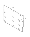
図3の上部側内扉の断熱材と内扉取付板の斜視図である。
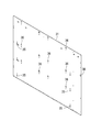
図3の上部側内扉の商品サンプル取付板の斜視図である。
図3の上部側内扉の要部拡大縦断側面図である。
従来の商品サンプル取付板の斜視図である。
[Supplement under rule 26 02.10.2013]
It is a front view of the vending machine of the Example to which this invention is applied. It is a perspective view of the state which opened the outer door of the vending machine of FIG. It is a perspective view of the upper side inner door of the vending machine of FIG. It is a disassembled perspective view of the upper side inner door of FIG. It is a perspective view of the heat insulating material and inner door mounting plate of the upper side inner door of FIG. It is a perspective view of the goods sample mounting plate of the upper side inner door of FIG. It is a principal part expansion vertical side view of the upper side inner door of FIG. It is a perspective view of the conventional goods sample mounting plate.
[規則26に基づく補充 02.10.2013]
以下、本発明の実施の形態について、詳細に説明する。図1は実施例の自動販売機1の正面図を示し、図2は外扉3を開いた状態の自動販売機1の斜視図をそれぞれ示している。実施例の自動販売機1は、前面が開口した断熱性の本体2と、この本体2の前面を開閉自在に閉塞するよう一側(実施例では向かって左側)が本体2に回動自在に枢支された外扉3を備えている。[Supplement underrule 26 02.10.2013]
Hereinafter, embodiments of the present invention will be described in detail. FIG. 1 shows a front view of thevending machine 1 of the embodiment, and FIG. 2 shows a perspective view of the vending machine 1 with the outer door 3 opened. The vending machine 1 according to the embodiment includes a heat-insulating main body 2 having an open front surface, and one side (in the embodiment, the left side) is freely rotatable with respect to the main body 2 so as to close the front surface of the main body 2 so that it can be opened and closed A pivoted outer door 3 is provided.
以下、本発明の実施の形態について、詳細に説明する。図1は実施例の自動販売機1の正面図を示し、図2は外扉3を開いた状態の自動販売機1の斜視図をそれぞれ示している。実施例の自動販売機1は、前面が開口した断熱性の本体2と、この本体2の前面を開閉自在に閉塞するよう一側(実施例では向かって左側)が本体2に回動自在に枢支された外扉3を備えている。[Supplement under
Hereinafter, embodiments of the present invention will be described in detail. FIG. 1 shows a front view of the
[規則26に基づく補充 02.10.2013]
この外扉3の前面上部には商品サンプル室4が構成されており、この商品サンプル室4内に陳列された複数の各商品サンプル(販売する商品のサンプル)に対応して複数の商品選択スイッチ6が配置されている。また、商品サンプル室4の下側の外扉3前面には、広告パネル(広告表示部)5が構成されており、この広告パネル5の下側の外扉3前面下部には商品取出口7が構成されている。[Supplement underrule 26 02.10.2013]
Aproduct sample chamber 4 is formed in the upper front portion of the outer door 3, and a plurality of product selection switches corresponding to a plurality of product samples (samples of products to be sold) displayed in the product sample chamber 4. 6 is arranged. An advertisement panel (advertisement display unit) 5 is formed on the front surface of the outer door 3 below the product sample chamber 4, and a product outlet 7 is disposed on the lower front surface of the outer door 3 below the advertisement panel 5. Is configured.
この外扉3の前面上部には商品サンプル室4が構成されており、この商品サンプル室4内に陳列された複数の各商品サンプル(販売する商品のサンプル)に対応して複数の商品選択スイッチ6が配置されている。また、商品サンプル室4の下側の外扉3前面には、広告パネル(広告表示部)5が構成されており、この広告パネル5の下側の外扉3前面下部には商品取出口7が構成されている。[Supplement under
A
[規則26に基づく補充 02.10.2013]
更に、外扉3前面の向かって右側(非枢支側)中央部には化粧パネル8が取り付けられており、この化粧パネル8内に位置して硬貨投入口9、返却レバー11が設けられている。また、この化粧パネル8の向かって左側の外扉3前面には、金額表示器12が取り付けられている。更に、この金額表示器12の下側の外扉3前面には紙幣識別装置(ビルバリ)14が取り付けられており、商品取出口7の向かって右側の外扉3前面には硬貨返却口13が構成されている。[Supplement underrule 26 02.10.2013]
Further, adecorative panel 8 is attached to the right side (non-pivot side) center of the front surface of the outer door 3, and a coin insertion slot 9 and a return lever 11 are provided in the decorative panel 8. Yes. A money amount indicator 12 is attached to the front surface of the left outer door 3 facing the decorative panel 8. Further, a bill recognition device (bill burr) 14 is attached to the front surface of the lower door 3 on the lower side of the money amount indicator 12, and a coin return port 13 is disposed on the front surface of the right outer door 3 toward the product outlet 7. It is configured.
更に、外扉3前面の向かって右側(非枢支側)中央部には化粧パネル8が取り付けられており、この化粧パネル8内に位置して硬貨投入口9、返却レバー11が設けられている。また、この化粧パネル8の向かって左側の外扉3前面には、金額表示器12が取り付けられている。更に、この金額表示器12の下側の外扉3前面には紙幣識別装置(ビルバリ)14が取り付けられており、商品取出口7の向かって右側の外扉3前面には硬貨返却口13が構成されている。[Supplement under
Further, a
[規則26に基づく補充 02.10.2013]
一方、本体2の内部には上下左右及び後面が断熱壁で囲繞され、前面が開口した商品収納部16が構成されており、この商品収納部16は断熱性の仕切板17によって左右方向が仕切られている。この仕切板17で仕切られた商品収納部16内には、販売する商品が蛇行状の商品通路に収納されるサーペンタイン式の商品収納コラム18が前後方向及び左右方向に複数設けられている。[Supplement underrule 26 02.10.2013]
On the other hand, the inside of themain body 2 includes a product storage section 16 whose upper, lower, left, and right and rear surfaces are surrounded by heat insulating walls, and the front surface is open. The product storage section 16 is partitioned in the left-right direction by a heat insulating partition plate 17. It has been. A plurality of serpentine-type product storage columns 18 in which products to be sold are stored in a meandering product passage are provided in the product storage section 16 partitioned by the partition plate 17 in the front-rear direction and the left-right direction.
一方、本体2の内部には上下左右及び後面が断熱壁で囲繞され、前面が開口した商品収納部16が構成されており、この商品収納部16は断熱性の仕切板17によって左右方向が仕切られている。この仕切板17で仕切られた商品収納部16内には、販売する商品が蛇行状の商品通路に収納されるサーペンタイン式の商品収納コラム18が前後方向及び左右方向に複数設けられている。[Supplement under
On the other hand, the inside of the
[規則26に基づく補充 02.10.2013]
商品収納部16の前面には、それぞれ断熱性を有し、商品収納部16の前面開口の上部側を開閉するための上部側内扉21(本発明の内扉)と、商品収納部16の前面開口の下部側を開閉するための下部側内扉22が設けられている。この下部側内扉22は本体2に回動自在に枢支されている。[Supplement underrule 26 02.10.2013]
The front side of theproduct storage unit 16 has heat insulation, and an upper inner door 21 (inner door of the present invention) for opening and closing the upper side of the front opening of the product storage unit 16, and the product storage unit 16 A lower side inner door 22 for opening and closing the lower side of the front opening is provided. The lower inner door 22 is pivotally supported by the main body 2.
商品収納部16の前面には、それぞれ断熱性を有し、商品収納部16の前面開口の上部側を開閉するための上部側内扉21(本発明の内扉)と、商品収納部16の前面開口の下部側を開閉するための下部側内扉22が設けられている。この下部側内扉22は本体2に回動自在に枢支されている。[Supplement under
The front side of the
[規則26に基づく補充 02.10.2013]
また、下部側内扉22の下部には商品収納部16側と外扉3側とを連通する商品搬出口23が左右方向に並設されている。各商品搬出口23には開閉自在の搬出扉24が上縁を中心して回動自在に取り付けられており、前方に案内される商品に押されて回転し、商品搬出口23を開放して商品を商品取出口7に搬出する構成とされている。また、商品収納部16の前側下部には、商品収納部16内において生じる結露水を受容するドレン受け26が設けられている。[Supplement underrule 26 02.10.2013]
Further, at the lower part of the lower sideinner door 22, a product outlet 23 that communicates the product storage unit 16 side and the outer door 3 side is provided side by side in the left-right direction. An openable / closable unloading door 24 is attached to each commodity unloading port 23 so as to be pivotable about the upper edge. The commodity unloading port 23 is opened by being pushed by the commodity guided forward to open the commodity. Is taken out to the product outlet 7. In addition, a drain receiver 26 that receives dew condensation water generated in the product storage unit 16 is provided at the front lower portion of the product storage unit 16.
また、下部側内扉22の下部には商品収納部16側と外扉3側とを連通する商品搬出口23が左右方向に並設されている。各商品搬出口23には開閉自在の搬出扉24が上縁を中心して回動自在に取り付けられており、前方に案内される商品に押されて回転し、商品搬出口23を開放して商品を商品取出口7に搬出する構成とされている。また、商品収納部16の前側下部には、商品収納部16内において生じる結露水を受容するドレン受け26が設けられている。[Supplement under
Further, at the lower part of the lower side
[規則26に基づく補充 02.10.2013]
他方、本発明の内扉としての上部側内扉21は、外扉3の商品サンプル室4の後側に対応して当該外扉3に取り付けられており、外扉3を開閉することにより、上部側内扉21によって商品収納部16の前面開口の上部側が開閉される構成とされている。更に、上部側内扉21は外扉3を開放した状態で、当該外扉3から独立して後方に開閉自在とされ、上部側内扉21を外扉3から後方に開いた状態で、商品サンプル室4内に陳列される商品サンプルを交換できるように構成されている。[Supplement underrule 26 02.10.2013]
On the other hand, the upperinner door 21 as the inner door of the present invention is attached to the outer door 3 corresponding to the rear side of the product sample chamber 4 of the outer door 3, and by opening and closing the outer door 3, The upper side of the front opening of the product storage unit 16 is opened and closed by the upper side inner door 21. Further, the upper inner door 21 can be opened and closed rearward independently of the outer door 3 with the outer door 3 open, and the upper inner door 21 can be opened rearward from the outer door 3 The product sample displayed in the sample chamber 4 can be exchanged.
他方、本発明の内扉としての上部側内扉21は、外扉3の商品サンプル室4の後側に対応して当該外扉3に取り付けられており、外扉3を開閉することにより、上部側内扉21によって商品収納部16の前面開口の上部側が開閉される構成とされている。更に、上部側内扉21は外扉3を開放した状態で、当該外扉3から独立して後方に開閉自在とされ、上部側内扉21を外扉3から後方に開いた状態で、商品サンプル室4内に陳列される商品サンプルを交換できるように構成されている。[Supplement under
On the other hand, the upper
[規則26に基づく補充 02.10.2013]
次に、図3乃至図7を参照して本発明に係る内扉の実施例としての上部側内扉21の構造について詳述する。実施例の上部側内扉21は、商品サンプル室4の背面となる商品サンプル取付板31と、その後側に間隔を存して設けられた断熱材32と、断熱材32の下側に設けられたカバー33等から構成されている。[Supplement underrule 26 02.10.2013]
Next, the structure of the upper sideinner door 21 as an embodiment of the inner door according to the present invention will be described in detail with reference to FIGS. The upper-side inner door 21 of the embodiment is provided on the lower side of the heat insulating material 32, the product sample mounting plate 31 that is the back surface of the product sample chamber 4, the heat insulating material 32 that is provided behind the product sample mounting plate 31. Cover 33 and the like.
次に、図3乃至図7を参照して本発明に係る内扉の実施例としての上部側内扉21の構造について詳述する。実施例の上部側内扉21は、商品サンプル室4の背面となる商品サンプル取付板31と、その後側に間隔を存して設けられた断熱材32と、断熱材32の下側に設けられたカバー33等から構成されている。[Supplement under
Next, the structure of the upper side
[規則26に基づく補充 02.10.2013]
商品サンプル取付板31は、上部側内扉21が外扉3の後側に閉じられた状態で商品サンプル室4の背面となるものであり、図6に示されるような薄い板金の塗装鋼板から成る矩形状の平板から構成されている。この商品サンプル取付板31には、商品サンプルを照明するためのLED照明装置34を取り付けるための複数の取付孔36や、商品サンプルを保持するための商品サンプル保持具50のブラケット40を取り付けるための複数の取付孔35、外扉3に係合するフック37が通過する透孔38等が形成されている。上記商品サンプル保持具50やLED照明装置34が本発明における商品サンプル取付板31前面に取り付けられる部材に相当する。実施例の商品サンプル保持具50は左右の前記ブラケット40と、それらの間に渡って取り付けられる商品サンプル棚45等から構成されている(図7)。そして、これら商品サンプル保持具50やLED照明装置34は商品サンプル取付板31の前面に複数段設けられる。尚、商品サンプル保持具50やLED照明装置34の位置は、陳列する商品サンプルの寸法等によって異なるので、取付孔35、36の位置は、販売する商品によって異なって来る。[Supplement underrule 26 02.10.2013]
The productsample mounting plate 31 is a back surface of the product sample chamber 4 in a state where the upper side inner door 21 is closed to the rear side of the outer door 3, and is made of a thin sheet metal coated steel plate as shown in FIG. It is comprised from the rectangular-shaped flat plate which consists of. A plurality of attachment holes 36 for attaching the LED illumination device 34 for illuminating the product sample and a bracket 40 of the product sample holder 50 for holding the product sample are attached to the product sample mounting plate 31. A plurality of mounting holes 35, a through hole 38 through which a hook 37 engaging with the outer door 3 passes, and the like are formed. The product sample holder 50 and the LED lighting device 34 correspond to members attached to the front surface of the product sample mounting plate 31 in the present invention. The product sample holder 50 according to the embodiment includes the left and right brackets 40 and a product sample shelf 45 attached between them (FIG. 7). The product sample holder 50 and the LED lighting device 34 are provided in a plurality of stages on the front surface of the product sample mounting plate 31. Note that the positions of the product sample holder 50 and the LED lighting device 34 differ depending on the size of the product sample to be displayed, and the positions of the mounting holes 35 and 36 differ depending on the products to be sold.
商品サンプル取付板31は、上部側内扉21が外扉3の後側に閉じられた状態で商品サンプル室4の背面となるものであり、図6に示されるような薄い板金の塗装鋼板から成る矩形状の平板から構成されている。この商品サンプル取付板31には、商品サンプルを照明するためのLED照明装置34を取り付けるための複数の取付孔36や、商品サンプルを保持するための商品サンプル保持具50のブラケット40を取り付けるための複数の取付孔35、外扉3に係合するフック37が通過する透孔38等が形成されている。上記商品サンプル保持具50やLED照明装置34が本発明における商品サンプル取付板31前面に取り付けられる部材に相当する。実施例の商品サンプル保持具50は左右の前記ブラケット40と、それらの間に渡って取り付けられる商品サンプル棚45等から構成されている(図7)。そして、これら商品サンプル保持具50やLED照明装置34は商品サンプル取付板31の前面に複数段設けられる。尚、商品サンプル保持具50やLED照明装置34の位置は、陳列する商品サンプルの寸法等によって異なるので、取付孔35、36の位置は、販売する商品によって異なって来る。[Supplement under
The product
[規則26に基づく補充 02.10.2013]
この場合、実施例では商品サンプル保持具50のブラケット40の後端から取付爪(取付構造)39が突出しており、この取付爪39が前面側から取付孔35に係合することで、商品サンプル保持具50は商品サンプル取付板31の前面に取り付けられる。そのため、取付爪39は商品サンプル取付板31の後側に突出することになる。尚、LED照明装置34はブラケット40の間に位置し、同様の取付構造で取付孔36に取り付けられるので、同じく商品サンプル取付板31の後側に突出することになる。[Supplement underrule 26 02.10.2013]
In this case, in the embodiment, a mounting claw (mounting structure) 39 protrudes from the rear end of thebracket 40 of the product sample holder 50, and this mounting claw 39 engages with the mounting hole 35 from the front side, thereby The holder 50 is attached to the front surface of the product sample mounting plate 31. Therefore, the mounting claw 39 protrudes to the rear side of the product sample mounting plate 31. Since the LED illumination device 34 is located between the brackets 40 and is attached to the attachment hole 36 with the same attachment structure, the LED illumination device 34 similarly protrudes to the rear side of the product sample attachment plate 31.
この場合、実施例では商品サンプル保持具50のブラケット40の後端から取付爪(取付構造)39が突出しており、この取付爪39が前面側から取付孔35に係合することで、商品サンプル保持具50は商品サンプル取付板31の前面に取り付けられる。そのため、取付爪39は商品サンプル取付板31の後側に突出することになる。尚、LED照明装置34はブラケット40の間に位置し、同様の取付構造で取付孔36に取り付けられるので、同じく商品サンプル取付板31の後側に突出することになる。[Supplement under
In this case, in the embodiment, a mounting claw (mounting structure) 39 protrudes from the rear end of the
[規則26に基づく補充 02.10.2013]
一方、断熱材32は実施例では発泡スチロールから成る成形断熱材であり、商品サンプル取付板31と略同じ幅寸法と、それよりも小さい上下寸法、及び、必要な断熱厚みを備えている。尚、実施例の発泡スチロールは成形が容易であるものの、従来のウレタンよりも断熱性能そのものは落ちるので、その分厚さ寸法を許容範囲で拡大する。但し、本発明では後述するような特徴により、上部側内扉21は十分なる断熱性能を維持することになる。この断熱材32の前面には、図5に示すように前方に突出した複数の突出部41が一体に成形されている。実施例の各突出部41は左右に渡って筋状に延在しており、その縦断面は実施例では図7に示すような半円形とされている。[Supplement underrule 26 02.10.2013]
On the other hand, theheat insulating material 32 is a molded heat insulating material made of polystyrene foam in the embodiment, and has substantially the same width dimension as that of the product sample mounting plate 31, a vertical dimension smaller than that, and a necessary heat insulating thickness. In addition, although the polystyrene foam of an Example is easy to shape | mold, since heat insulation performance itself falls rather than the conventional urethane, the thickness dimension is expanded in the permissible range. However, in the present invention, the upper side inner door 21 maintains sufficient heat insulating performance due to the characteristics described later. On the front surface of the heat insulating material 32, a plurality of projecting portions 41 projecting forward are integrally formed as shown in FIG. Each protrusion 41 of the embodiment extends in a streak shape from side to side, and the longitudinal section thereof is a semicircular shape as shown in FIG. 7 in the embodiment.
一方、断熱材32は実施例では発泡スチロールから成る成形断熱材であり、商品サンプル取付板31と略同じ幅寸法と、それよりも小さい上下寸法、及び、必要な断熱厚みを備えている。尚、実施例の発泡スチロールは成形が容易であるものの、従来のウレタンよりも断熱性能そのものは落ちるので、その分厚さ寸法を許容範囲で拡大する。但し、本発明では後述するような特徴により、上部側内扉21は十分なる断熱性能を維持することになる。この断熱材32の前面には、図5に示すように前方に突出した複数の突出部41が一体に成形されている。実施例の各突出部41は左右に渡って筋状に延在しており、その縦断面は実施例では図7に示すような半円形とされている。[Supplement under
On the other hand, the
[規則26に基づく補充 02.10.2013]
但し、商品サンプル保持具50やLED照明装置34を取り付けるための商品サンプル取付板31の取付孔35、36の位置は、前述したように販売する商品(陳列する商品サンプルの寸法)によって異なってくるので、取付孔35、36が形成されると想定される範囲(商品サンプル取付板31に取付孔35、36が形成される可能性のある範囲)に対応する部分には突出部41は形成されていない(図5にXで示す部分)。[Supplement underrule 26 02.10.2013]
However, the positions of the mounting holes 35 and 36 of the product sample mounting plate 31 for mounting the product sample holder 50 and the LED lighting device 34 differ depending on the products to be sold (the dimensions of the product samples to be displayed). Therefore, the protrusion 41 is formed in a portion corresponding to a range in which the mounting holes 35 and 36 are assumed to be formed (a range in which the mounting holes 35 and 36 may be formed in the product sample mounting plate 31). (The part indicated by X in FIG. 5).
但し、商品サンプル保持具50やLED照明装置34を取り付けるための商品サンプル取付板31の取付孔35、36の位置は、前述したように販売する商品(陳列する商品サンプルの寸法)によって異なってくるので、取付孔35、36が形成されると想定される範囲(商品サンプル取付板31に取付孔35、36が形成される可能性のある範囲)に対応する部分には突出部41は形成されていない(図5にXで示す部分)。[Supplement under
However, the positions of the mounting
[規則26に基づく補充 02.10.2013]
また、断熱材32の前面の向かって左側には、突出部41が上下に渡って連続して形成されていない部分が二カ所一体成形され、それぞれ排水溝42、配線収納部43とされる。また、断熱材32の前面の突出部41以外の部分、実施例では左右に延在する突出部41の上側には左右に渡ってパッキン44が複数取り付けられている(図4では省略)。各パッキン44は連続気泡のスポンジ等から構成されており、排水溝42及び配線収納部43まで渡っている。このとき、実施例では突出部41も左右に渡っているので、パッキン44を取り付ける際には、突出部41に沿ってそれらの間に配置すれば良くなり、取付作業性が良好となる。[Supplement underrule 26 02.10.2013]
In addition, on the left side of the front surface of theheat insulating material 32, the portions where the protruding portions 41 are not continuously formed in the up and down direction are integrally formed at two places, which are the drainage groove 42 and the wiring storage portion 43, respectively. In addition, a plurality of packings 44 are attached to the left and right sides of the heat insulating material 32 other than the protruding portion 41, in the embodiment, on the upper side of the protruding portion 41 extending left and right (not shown in FIG. 4). Each packing 44 is composed of an open-cell sponge or the like, and extends to the drainage groove 42 and the wiring storage portion 43. At this time, since the protruding portion 41 also extends to the left and right in the embodiment, when the packing 44 is attached, it is only necessary to arrange the packing 44 along the protruding portion 41, and the attachment workability is improved.
また、断熱材32の前面の向かって左側には、突出部41が上下に渡って連続して形成されていない部分が二カ所一体成形され、それぞれ排水溝42、配線収納部43とされる。また、断熱材32の前面の突出部41以外の部分、実施例では左右に延在する突出部41の上側には左右に渡ってパッキン44が複数取り付けられている(図4では省略)。各パッキン44は連続気泡のスポンジ等から構成されており、排水溝42及び配線収納部43まで渡っている。このとき、実施例では突出部41も左右に渡っているので、パッキン44を取り付ける際には、突出部41に沿ってそれらの間に配置すれば良くなり、取付作業性が良好となる。[Supplement under
In addition, on the left side of the front surface of the
[規則26に基づく補充 02.10.2013]
更に、断熱材32の周縁部32Aは突出部41と同様に前方に突出しており、左右の縁部32Aには厚肉の鋼板から成る内扉取付板46がインサート成形により一体に埋め込まれている。実施例では左右の内扉取付板46は同一のものを上下反転させて使用しており、向かって右側の内扉取付板46には前記フック37が取り付けられ、向かって左側の内扉取付板46には外扉3に上部側内扉21を回動自在に取り付けるための上側のヒンジ47が取り付けられる。また、前記排水溝42と配線収納部43の下端に対応する縁部32Aには切欠部32Bがそれぞれ形成されている。[Supplement underrule 26 02.10.2013]
Further, theperipheral edge portion 32A of the heat insulating material 32 protrudes forward similarly to the protruding portion 41, and inner door mounting plates 46 made of thick steel plates are integrally embedded in the left and right edge portions 32A by insert molding. . In the embodiment, the left and right inner door mounting plates 46 are used by turning the same one upside down, and the hook 37 is mounted on the right inner door mounting plate 46 and the left inner door mounting plate is facing. An upper hinge 47 for attaching the upper side inner door 21 to the outer door 3 so as to be rotatable is attached to the outer door 3. Further, a notch 32B is formed in the edge 32A corresponding to the drainage groove 42 and the lower end of the wiring storage part 43, respectively.
更に、断熱材32の周縁部32Aは突出部41と同様に前方に突出しており、左右の縁部32Aには厚肉の鋼板から成る内扉取付板46がインサート成形により一体に埋め込まれている。実施例では左右の内扉取付板46は同一のものを上下反転させて使用しており、向かって右側の内扉取付板46には前記フック37が取り付けられ、向かって左側の内扉取付板46には外扉3に上部側内扉21を回動自在に取り付けるための上側のヒンジ47が取り付けられる。また、前記排水溝42と配線収納部43の下端に対応する縁部32Aには切欠部32Bがそれぞれ形成されている。[Supplement under
Further, the
[規則26に基づく補充 02.10.2013]
他方、カバー33は鋼板から成り、商品サンプル取付板31と略同じ幅寸法と、それと断熱材32の上下方向の寸法差分の上下寸法を有している。カバー33の下縁には前方に折曲された排水受け48が形成されており、この排水受け48の向かって左側には排水部49が切欠形成されている(図4)。[Supplement underrule 26 02.10.2013]
On the other hand, thecover 33 is made of a steel plate and has substantially the same width as that of the product sample mounting plate 31 and the vertical dimension of the dimensional difference in the vertical direction of the heat insulating material 32. A drainage receptacle 48 bent forward is formed at the lower edge of the cover 33, and a drainage portion 49 is cut out on the left side of the drainage receptacle 48 (FIG. 4).
他方、カバー33は鋼板から成り、商品サンプル取付板31と略同じ幅寸法と、それと断熱材32の上下方向の寸法差分の上下寸法を有している。カバー33の下縁には前方に折曲された排水受け48が形成されており、この排水受け48の向かって左側には排水部49が切欠形成されている(図4)。[Supplement under
On the other hand, the
[規則26に基づく補充 02.10.2013]
そして、商品サンプル取付板31は断熱材32に前方から被せられ、その周縁部が断熱材32の周縁部32A前面に宛がわれる。この状態で商品サンプル取付板31の左右縁部を断熱材32に埋め込まれた内扉取付板46にそれぞれネジ止めすることにより、商品サンプル取付板31を断熱材32に取り付ける。また、カバー33は断熱材32に下方から宛がわれ、その左右縁上端を断熱材32の内扉取付板46にネジ止めする。更に、左右縁及び下縁部を商品サンプル取付板31の縁部にネジ止めすることで、商品サンプル取付板31下部の後側で断熱材32の下側にカバー33を取り付ける。[Supplement underrule 26 02.10.2013]
The productsample mounting plate 31 is placed on the heat insulating material 32 from the front, and the peripheral edge thereof is directed to the front surface of the peripheral edge portion 32 </ b> A of the heat insulating material 32. In this state, the product sample mounting plate 31 is attached to the heat insulating material 32 by screwing the left and right edges of the product sample mounting plate 31 to the inner door mounting plate 46 embedded in the heat insulating material 32. Further, the cover 33 is addressed to the heat insulating material 32 from below, and the upper ends of the left and right edges are screwed to the inner door mounting plate 46 of the heat insulating material 32. Furthermore, the cover 33 is attached to the lower side of the heat insulating material 32 on the rear side of the lower part of the product sample mounting plate 31 by screwing the left and right edges and the lower edge to the edge of the product sample mounting plate 31.
そして、商品サンプル取付板31は断熱材32に前方から被せられ、その周縁部が断熱材32の周縁部32A前面に宛がわれる。この状態で商品サンプル取付板31の左右縁部を断熱材32に埋め込まれた内扉取付板46にそれぞれネジ止めすることにより、商品サンプル取付板31を断熱材32に取り付ける。また、カバー33は断熱材32に下方から宛がわれ、その左右縁上端を断熱材32の内扉取付板46にネジ止めする。更に、左右縁及び下縁部を商品サンプル取付板31の縁部にネジ止めすることで、商品サンプル取付板31下部の後側で断熱材32の下側にカバー33を取り付ける。[Supplement under
The product
[規則26に基づく補充 02.10.2013]
尚、カバー33の向かって左側には、外扉3に上部側内扉21を回動自在に取り付けるための下側のヒンジ47を取り付ける。また、フック37は透孔38から前方に突出する。そして、このように組み立てた上部側内扉21を上下のヒンジ47を用いて外扉3の商品サンプル室4後側に対応する位置に回動自在に枢支する。また、外扉3を閉じた状態では、下部側内扉22の上部はカバー33の後側に重合するかたちとなる。[Supplement underrule 26 02.10.2013]
On the left side of thecover 33, a lower hinge 47 for attaching the upper inner door 21 to the outer door 3 is attached. Further, the hook 37 protrudes forward from the through hole 38. And the upper side inner door 21 assembled in this way is pivotally supported at a position corresponding to the rear side of the product sample chamber 4 of the outer door 3 using the upper and lower hinges 47. When the outer door 3 is closed, the upper portion of the lower side inner door 22 is superposed on the rear side of the cover 33.
尚、カバー33の向かって左側には、外扉3に上部側内扉21を回動自在に取り付けるための下側のヒンジ47を取り付ける。また、フック37は透孔38から前方に突出する。そして、このように組み立てた上部側内扉21を上下のヒンジ47を用いて外扉3の商品サンプル室4後側に対応する位置に回動自在に枢支する。また、外扉3を閉じた状態では、下部側内扉22の上部はカバー33の後側に重合するかたちとなる。[Supplement under
On the left side of the
[規則26に基づく補充 02.10.2013]
このように組み立てられた上部側内扉21の商品サンプル取付板31と断熱材32間の前記Xの部分には周縁部32Aの高さ分の間隔Gが構成されるので、商品サンプル取付板31の前面に取り付けられる部材である商品サンプル保持具50の取付爪39(取付構造)やLED照明装置34の取付構造を逃げることができる。また、断熱材32の突出部41の前端は商品サンプル取付板31の後面に線接触で当接(部分的に当接)し、薄い板金から成る商品サンプル取付板31を後側から支える。更に、パッキン44は商品サンプル取付板31の後面に当接する(図7)。[Supplement underrule 26 02.10.2013]
Since the gap X corresponding to the height of theperipheral portion 32A is formed in the portion X between the product sample mounting plate 31 and the heat insulating material 32 of the upper inner door 21 assembled in this way, the product sample mounting plate 31 The attachment claw 39 (attachment structure) of the product sample holder 50 and the attachment structure of the LED lighting device 34 which are members attached to the front surface of the LED illumination device 34 can be escaped. Further, the front end of the protruding portion 41 of the heat insulating material 32 abuts (partially abuts) the rear surface of the product sample mounting plate 31 by line contact, and supports the product sample mounting plate 31 made of a thin sheet metal from the rear side. Further, the packing 44 contacts the rear surface of the product sample mounting plate 31 (FIG. 7).
このように組み立てられた上部側内扉21の商品サンプル取付板31と断熱材32間の前記Xの部分には周縁部32Aの高さ分の間隔Gが構成されるので、商品サンプル取付板31の前面に取り付けられる部材である商品サンプル保持具50の取付爪39(取付構造)やLED照明装置34の取付構造を逃げることができる。また、断熱材32の突出部41の前端は商品サンプル取付板31の後面に線接触で当接(部分的に当接)し、薄い板金から成る商品サンプル取付板31を後側から支える。更に、パッキン44は商品サンプル取付板31の後面に当接する(図7)。[Supplement under
Since the gap X corresponding to the height of the
[規則26に基づく補充 02.10.2013]
また、配線収納部43と商品サンプル取付板31との間にも間隔Gが構成されるので、LED照明装置34からの配線をこの配線収納部43内に収納し、切欠部32Bから引き出す(パッキン44は配線部分のみ潰れる)。[Supplement underrule 26 02.10.2013]
Further, since the gap G is also formed between thewiring storage portion 43 and the product sample mounting plate 31, the wiring from the LED lighting device 34 is stored in the wiring storage portion 43 and pulled out from the cutout portion 32B (packing). 44 is collapsed only in the wiring part).
また、配線収納部43と商品サンプル取付板31との間にも間隔Gが構成されるので、LED照明装置34からの配線をこの配線収納部43内に収納し、切欠部32Bから引き出す(パッキン44は配線部分のみ潰れる)。[Supplement under
Further, since the gap G is also formed between the
[規則26に基づく補充 02.10.2013]
また、排水溝42と商品サンプル取付板31との間にも間隔Gが構成される。ここで、商品サンプル取付板31の後面に結露が成長した場合、結露水はパッキン44に吸収され、そこで蒸発するか、或いは、その内部を伝って排水溝42に至る。このとき、突出部41は左右に渡って形成され、且つ、パッキン44はその上側において左右に渡って設けられ、排水溝42まで渡っているので、結露水がパッキン44から下方に流下してしまうことを突出部41で阻止することができる。これにより、排水溝42から離れた位置の商品サンプル取付板31後面の結露水も、蒸発しきれないものはパッキン44を伝って排水溝42に向かうことになる。この排水溝42まで来た結露水はパッキン44からしみ出した後、排水溝42内を下方に流れ、切欠部32Bからカバー33内に入り、流下して排水受け48に受容される。そして、排水部49から下方に流出し、前述したドレン受け26等に案内されて処理されることになる。[Supplement underrule 26 02.10.2013]
Further, a gap G is also formed between thedrainage groove 42 and the product sample mounting plate 31. Here, when dew condensation grows on the rear surface of the product sample mounting plate 31, the dew condensation water is absorbed by the packing 44 and evaporates there, or reaches the drainage groove 42 through the inside thereof. At this time, the protruding portion 41 is formed on the left and right sides, and the packing 44 is provided on the upper side on the left and right sides and extends to the drainage groove 42, so that the condensed water flows downward from the packing 44. This can be prevented by the protrusion 41. As a result, the condensed water on the rear surface of the product sample mounting plate 31 at a position away from the drainage groove 42 also cannot be evaporated and travels to the drainage groove 42 through the packing 44. The condensed water that has reached the drain groove 42 oozes out from the packing 44, then flows downward in the drain groove 42, enters the cover 33 through the notch 32 </ b> B, flows down, and is received by the drain receiver 48. Then, it flows downward from the drainage part 49 and is guided and processed by the drain receiver 26 described above.
また、排水溝42と商品サンプル取付板31との間にも間隔Gが構成される。ここで、商品サンプル取付板31の後面に結露が成長した場合、結露水はパッキン44に吸収され、そこで蒸発するか、或いは、その内部を伝って排水溝42に至る。このとき、突出部41は左右に渡って形成され、且つ、パッキン44はその上側において左右に渡って設けられ、排水溝42まで渡っているので、結露水がパッキン44から下方に流下してしまうことを突出部41で阻止することができる。これにより、排水溝42から離れた位置の商品サンプル取付板31後面の結露水も、蒸発しきれないものはパッキン44を伝って排水溝42に向かうことになる。この排水溝42まで来た結露水はパッキン44からしみ出した後、排水溝42内を下方に流れ、切欠部32Bからカバー33内に入り、流下して排水受け48に受容される。そして、排水部49から下方に流出し、前述したドレン受け26等に案内されて処理されることになる。[Supplement under
Further, a gap G is also formed between the
[規則26に基づく補充 02.10.2013]
以上詳述した如く本発明では上部側内扉21の断熱材32前面に、商品サンプル取付板31の後面に部分的に当接する突出部41を一体に成形したので、薄い板金から構成された商品サンプル取付板31を、断熱材32の突出部41にて後から支えることができるようになり、上部側内扉21を補強してその構造上の安定度を向上させることができるようになる。[Supplement underrule 26 02.10.2013]
As described above in detail, in the present invention, since theprotrusion 41 that partially contacts the rear surface of the product sample mounting plate 31 is integrally formed on the front surface of the heat insulating material 32 of the upper inner door 21, the product made of thin sheet metal. The sample mounting plate 31 can be supported later by the projecting portion 41 of the heat insulating material 32, and the upper side inner door 21 can be reinforced to improve the structural stability thereof.
以上詳述した如く本発明では上部側内扉21の断熱材32前面に、商品サンプル取付板31の後面に部分的に当接する突出部41を一体に成形したので、薄い板金から構成された商品サンプル取付板31を、断熱材32の突出部41にて後から支えることができるようになり、上部側内扉21を補強してその構造上の安定度を向上させることができるようになる。[Supplement under
As described above in detail, in the present invention, since the
[規則26に基づく補充 02.10.2013]
また、突出部41は部分的に商品サンプル取付板31に当接するので、商品サンプル保持具50やLED照明装置34の取り付けにも支障は生じない。また、突出部41は断熱材32と一体に成形されているので、部品点数の増大によるコストの高騰も生じない。更に、突出部41が断熱32材と商品サンプル取付板31間の間隔Gに存在することで、この間隔Gにおける空気の対流が抑制され、上部側内扉21の断熱性能が向上する。[Supplement underrule 26 02.10.2013]
Further, since the protrudingportion 41 partially abuts on the product sample mounting plate 31, there is no problem in mounting the product sample holder 50 and the LED lighting device 34. Moreover, since the protrusion 41 is formed integrally with the heat insulating material 32, the cost does not increase due to an increase in the number of parts. Furthermore, the protrusion 41 is present in the gap G between the heat insulation 32 material and the product sample mounting plate 31, so that air convection in the gap G is suppressed and the heat insulation performance of the upper inner door 21 is improved.
また、突出部41は部分的に商品サンプル取付板31に当接するので、商品サンプル保持具50やLED照明装置34の取り付けにも支障は生じない。また、突出部41は断熱材32と一体に成形されているので、部品点数の増大によるコストの高騰も生じない。更に、突出部41が断熱32材と商品サンプル取付板31間の間隔Gに存在することで、この間隔Gにおける空気の対流が抑制され、上部側内扉21の断熱性能が向上する。[Supplement under
Further, since the protruding
[規則26に基づく補充 02.10.2013]
特に、実施例では突出部41を断面半円形に形成しており、その前端は商品サンプル取付板41の後面に線接触するので、断熱材32を介して商品サンプル取付板31に商品収納部16から直接伝導する冷却作用も最小限に抑えられるようになる。従って、上部側内扉21の断熱性能が低下することも無く、商品サンプル取付板31の後面や前面に成長する結露水も抑制される。[Supplement underrule 26 02.10.2013]
In particular, in the embodiment, the protrudingportion 41 is formed in a semicircular cross section, and the front end thereof is in line contact with the rear surface of the product sample mounting plate 41, so that the product storage portion 16 is attached to the product sample mounting plate 31 via the heat insulating material 32. The cooling effect directly conducted from the air can be minimized. Therefore, the heat insulation performance of the upper side inner door 21 is not lowered, and the dew condensation water that grows on the rear surface or front surface of the product sample mounting plate 31 is also suppressed.
特に、実施例では突出部41を断面半円形に形成しており、その前端は商品サンプル取付板41の後面に線接触するので、断熱材32を介して商品サンプル取付板31に商品収納部16から直接伝導する冷却作用も最小限に抑えられるようになる。従って、上部側内扉21の断熱性能が低下することも無く、商品サンプル取付板31の後面や前面に成長する結露水も抑制される。[Supplement under
In particular, in the embodiment, the protruding
[規則26に基づく補充 02.10.2013]
また、前述したように商品サンプル保持具50やLED照明装置34が取り付けられると想定される範囲の商品サンプル取付板31に対応する部分(図5のXの部分)には、突出部41を形成していないので、商品サンプル保持具50やLED照明装置34の取付位置、即ち、取付孔36の位置が陳列する商品サンプルの寸法によって異なる複数種の商品サンプル取付板31に対し、断熱材32を兼用することができるようになり、汎用性の良いものとなる。[Supplement underrule 26 02.10.2013]
Further, as described above, theprotrusion 41 is formed in the portion (X portion in FIG. 5) corresponding to the product sample mounting plate 31 in the range where the product sample holder 50 and the LED lighting device 34 are assumed to be attached. Since the mounting position of the product sample holder 50 and the LED lighting device 34, that is, the position of the mounting hole 36 is different depending on the size of the product sample to be displayed, the heat insulating material 32 is provided to the plurality of types of product sample mounting plates 31. It becomes possible to use both, and it becomes versatile.
また、前述したように商品サンプル保持具50やLED照明装置34が取り付けられると想定される範囲の商品サンプル取付板31に対応する部分(図5のXの部分)には、突出部41を形成していないので、商品サンプル保持具50やLED照明装置34の取付位置、即ち、取付孔36の位置が陳列する商品サンプルの寸法によって異なる複数種の商品サンプル取付板31に対し、断熱材32を兼用することができるようになり、汎用性の良いものとなる。[Supplement under
Further, as described above, the
[規則26に基づく補充 02.10.2013]
また、断熱材32の前面には、商品サンプル取付板31の後側に間隔Gを存して、当該商品サンプル取付板31の後面で成長する結露水を流下させるための排水溝42を上下に渡って一体に成形しているので、商品サンプル取付板31の後面に生じた結露水を、排水溝42により円滑に排出することができるようになる。この場合も排水溝42は断熱材32と一体に成形されているので、排水構造が簡素化され、部品点数の削減によるコストの低減を図ることが可能となる。[Supplement underrule 26 02.10.2013]
In addition, on the front surface of theheat insulating material 32, there is a gap G on the rear side of the product sample mounting plate 31, and a drainage groove 42 for flowing down the condensed water that grows on the rear surface of the product sample mounting plate 31. Since it is integrally formed across the body, the condensed water generated on the rear surface of the product sample mounting plate 31 can be smoothly discharged by the drainage groove 42. Also in this case, since the drainage groove 42 is formed integrally with the heat insulating material 32, the drainage structure is simplified, and the cost can be reduced by reducing the number of parts.
また、断熱材32の前面には、商品サンプル取付板31の後側に間隔Gを存して、当該商品サンプル取付板31の後面で成長する結露水を流下させるための排水溝42を上下に渡って一体に成形しているので、商品サンプル取付板31の後面に生じた結露水を、排水溝42により円滑に排出することができるようになる。この場合も排水溝42は断熱材32と一体に成形されているので、排水構造が簡素化され、部品点数の削減によるコストの低減を図ることが可能となる。[Supplement under
In addition, on the front surface of the
[規則26に基づく補充 02.10.2013]
更に、排水溝42を含む断熱材32の前面に、商品サンプル取付板31の後面に当接する連続気泡のパッキン44を左右に渡って設けているので、排水溝42から離れた位置に成長した結露水をパッキン44にて吸収し、蒸発処理、或いは、排水溝42まで導いて排出処理することができるようになる。また、パッキン44が左右に渡って設けられ、断熱材32と商品サンプル取付板31間の間隔Gを上下で区画することになるので、間隔G内に下方から流入してくる空気や、間隔G内における上下方向の空気の対流が阻止され、これによっても上部側内扉21の断熱性能が向上する。[Supplement underrule 26 02.10.2013]
Further, since the open-cell packing 44 that abuts against the rear surface of the productsample mounting plate 31 is provided on the front side of the heat insulating material 32 including the drainage groove 42, the dew condensation that has grown away from the drainage groove 42. Water is absorbed by the packing 44 and can be discharged by being evaporated or led to the drainage groove 42. In addition, since the packing 44 is provided on the left and right sides, and the gap G between the heat insulating material 32 and the product sample mounting plate 31 is vertically divided, the air flowing into the gap G from below or the gap G The convection of the air in the vertical direction in the inside is prevented, and this also improves the heat insulating performance of the upper side inner door 21.
更に、排水溝42を含む断熱材32の前面に、商品サンプル取付板31の後面に当接する連続気泡のパッキン44を左右に渡って設けているので、排水溝42から離れた位置に成長した結露水をパッキン44にて吸収し、蒸発処理、或いは、排水溝42まで導いて排出処理することができるようになる。また、パッキン44が左右に渡って設けられ、断熱材32と商品サンプル取付板31間の間隔Gを上下で区画することになるので、間隔G内に下方から流入してくる空気や、間隔G内における上下方向の空気の対流が阻止され、これによっても上部側内扉21の断熱性能が向上する。[Supplement under
Further, since the open-cell packing 44 that abuts against the rear surface of the product
[規則26に基づく補充 02.10.2013]
また、断熱材32の前面には、商品サンプル取付板31の後側に間隔Gを存して、配線を収納するための配線収納部43を一体に成形しているので、商品サンプル取付板31から引き出された(或いは、商品サンプル取付板31に向かう)配線を、この配線収納部43に収納することができるようになり、格別な配線収納具を取り付ける必要がなくなって、部品点数の簡素化を図ることが可能となる。[Supplement underrule 26 02.10.2013]
In addition, since thewiring storage portion 43 for storing the wiring is integrally formed on the front surface of the heat insulating material 32 with a gap G behind the product sample mounting plate 31, the product sample mounting plate 31. Wiring drawn from (or toward the product sample mounting plate 31) can be stored in the wiring storage portion 43, and it is not necessary to attach a special wiring storage tool, thus simplifying the number of parts. Can be achieved.
また、断熱材32の前面には、商品サンプル取付板31の後側に間隔Gを存して、配線を収納するための配線収納部43を一体に成形しているので、商品サンプル取付板31から引き出された(或いは、商品サンプル取付板31に向かう)配線を、この配線収納部43に収納することができるようになり、格別な配線収納具を取り付ける必要がなくなって、部品点数の簡素化を図ることが可能となる。[Supplement under
In addition, since the
[規則26に基づく補充 02.10.2013]
そして、商品サンプル取付板31を断熱材32に取り付けるための内扉取付板46を、断熱材32にインサート成形により、一体に埋め込んでいるので、塗装鋼板にて構成された商品サンプル取付板31に、従来のような複雑な曲げ加工を施すこと無く、断熱材32に一体に埋め込まれた内扉取付板46に商品サンプル取付板31を取り付けることができるようになり、商品サンプル取付板31の形状を著しく簡素化することができるようになって、コストダウンを達成することが可能となる。[Supplement underrule 26 02.10.2013]
And since the innerdoor mounting plate 46 for mounting the product sample mounting plate 31 to the heat insulating material 32 is integrally embedded in the heat insulating material 32 by insert molding, the product sample mounting plate 31 made of a coated steel plate is used. The product sample mounting plate 31 can be attached to the inner door mounting plate 46 that is integrally embedded in the heat insulating material 32 without performing a complicated bending process as in the prior art. As a result, the cost can be reduced.
そして、商品サンプル取付板31を断熱材32に取り付けるための内扉取付板46を、断熱材32にインサート成形により、一体に埋め込んでいるので、塗装鋼板にて構成された商品サンプル取付板31に、従来のような複雑な曲げ加工を施すこと無く、断熱材32に一体に埋め込まれた内扉取付板46に商品サンプル取付板31を取り付けることができるようになり、商品サンプル取付板31の形状を著しく簡素化することができるようになって、コストダウンを達成することが可能となる。[Supplement under
And since the inner
[規則26に基づく補充 02.10.2013]
また、図8に示した従来の商品サンプル取付板100のような、断熱材を囲い込む曲げ加工101が必要なくなり、商品サンプル取付板31としては平板を使用できるので、曲げ加工101部分から回り込んで商品収納部から商品サンプル取付板100に直接伝導する冷却作用も解消若しくは抑制される。これによっても上部側内扉21の断熱性能は一段と向上する。更に、この内扉取付板46にヒンジ47を取り付け、上部側内扉21を外扉3に取り付けるようにしているので、上部側内扉21を外扉3に取り付けるための構造も簡素化することができ、一層のコストの削減を図ることが可能となる。[Supplement underrule 26 02.10.2013]
Further, unlike the conventional productsample mounting plate 100 shown in FIG. 8, the bending process 101 for enclosing the heat insulating material is not necessary, and a flat plate can be used as the product sample mounting plate 31. Thus, the cooling effect conducted directly from the product storage unit to the product sample mounting plate 100 is also eliminated or suppressed. Also by this, the heat insulation performance of the upper side inner door 21 is further improved. Further, since the hinge 47 is attached to the inner door mounting plate 46 and the upper side inner door 21 is attached to the outer door 3, the structure for attaching the upper side inner door 21 to the outer door 3 is simplified. Thus, further cost reduction can be achieved.
また、図8に示した従来の商品サンプル取付板100のような、断熱材を囲い込む曲げ加工101が必要なくなり、商品サンプル取付板31としては平板を使用できるので、曲げ加工101部分から回り込んで商品収納部から商品サンプル取付板100に直接伝導する冷却作用も解消若しくは抑制される。これによっても上部側内扉21の断熱性能は一段と向上する。更に、この内扉取付板46にヒンジ47を取り付け、上部側内扉21を外扉3に取り付けるようにしているので、上部側内扉21を外扉3に取り付けるための構造も簡素化することができ、一層のコストの削減を図ることが可能となる。[Supplement under
Further, unlike the conventional product
[規則26に基づく補充 02.10.2013]
それに加えて断熱材32の下側に設けられて商品サンプル取付板31からの結露水を受ける排水受け48が形成されたカバー33を内扉取付板46に取り付けているので、結露水を排出するための機能を奏するカバー33を上部側内扉21に取り付けるための構造も簡素化することができるようになる。[Supplement underrule 26 02.10.2013]
In addition, since thecover 33 provided with the drainage receptacle 48 provided under the heat insulating material 32 and receiving the condensed water from the product sample mounting plate 31 is attached to the inner door mounting plate 46, the condensed water is discharged. Therefore, the structure for attaching the cover 33 having the function to the upper side inner door 21 can be simplified.
それに加えて断熱材32の下側に設けられて商品サンプル取付板31からの結露水を受ける排水受け48が形成されたカバー33を内扉取付板46に取り付けているので、結露水を排出するための機能を奏するカバー33を上部側内扉21に取り付けるための構造も簡素化することができるようになる。[Supplement under
In addition, since the
[規則26に基づく補充 02.10.2013]
尚、上記実施例では商品サンプル保持具50のブラケット40に取付爪39を一体に形成したが、それに限らず、別体のネジやクリップで取付孔35に商品サンプル保持具50を取り付けても良い(LED照明装置34の取付構造も同様)。また、実施例では突出部41を縦断面半円形の筋状に形成したが、それに限らず、例えば断面が三角形となるものでもよい。[Supplement underrule 26 02.10.2013]
In the above embodiment, the mountingclaw 39 is formed integrally with the bracket 40 of the product sample holder 50. However, the present invention is not limited to this, and the product sample holder 50 may be attached to the mounting hole 35 with a separate screw or clip. (The mounting structure of the LED lighting device 34 is also the same). In the embodiment, the protruding portion 41 is formed in a semicircular shape with a semicircular vertical cross section. However, the invention is not limited thereto, and the cross section may be triangular, for example.
尚、上記実施例では商品サンプル保持具50のブラケット40に取付爪39を一体に形成したが、それに限らず、別体のネジやクリップで取付孔35に商品サンプル保持具50を取り付けても良い(LED照明装置34の取付構造も同様)。また、実施例では突出部41を縦断面半円形の筋状に形成したが、それに限らず、例えば断面が三角形となるものでもよい。[Supplement under
In the above embodiment, the mounting
[規則26に基づく補充 02.10.2013]
また、実施例では断熱材32の前面に突出部41を左右に渡って形成したが、それに限らず、上下に渡って筋状に形成してもよい。その場合でも商品サンプル取付板31を支える効果を十分に奏することになる。[Supplement underrule 26 02.10.2013]
Moreover, in the Example, although theprotrusion part 41 was formed over the left and right in the front surface of the heat insulating material 32, you may form not only in it but a streak shape over the upper and lower sides. Even in such a case, the effect of supporting the product sample mounting plate 31 is sufficiently exhibited.
また、実施例では断熱材32の前面に突出部41を左右に渡って形成したが、それに限らず、上下に渡って筋状に形成してもよい。その場合でも商品サンプル取付板31を支える効果を十分に奏することになる。[Supplement under
Moreover, in the Example, although the
[規則26に基づく補充 02.10.2013]
更に、筋状以外にも突起状の突出部を断熱材32の前面に複数突出形成してもよい。それによれば、突出部41と商品サンプル取付板31とは点接触になるので、熱伝導を一層抑制することが可能となる。また、実施例では上部側内扉21と下部側内扉22を有する自動販売機1の上部側内扉21に本発明を適用したが、外扉の後側に一枚の内扉を備えたものにも本発明が有効であることは云うまでもない。[Supplement underrule 26 02.10.2013]
Further, a plurality of protruding protrusions may be formed on the front surface of theheat insulating material 32 in addition to the streaks. According to this, since the protrusion 41 and the product sample mounting plate 31 are in point contact, it is possible to further suppress heat conduction. In the embodiment, the present invention is applied to the upper side inner door 21 of the vending machine 1 having the upper side inner door 21 and the lower side inner door 22, but a single inner door is provided on the rear side of the outer door. Needless to say, the present invention is also effective.
更に、筋状以外にも突起状の突出部を断熱材32の前面に複数突出形成してもよい。それによれば、突出部41と商品サンプル取付板31とは点接触になるので、熱伝導を一層抑制することが可能となる。また、実施例では上部側内扉21と下部側内扉22を有する自動販売機1の上部側内扉21に本発明を適用したが、外扉の後側に一枚の内扉を備えたものにも本発明が有効であることは云うまでもない。[Supplement under
Further, a plurality of protruding protrusions may be formed on the front surface of the
[規則26に基づく補充 02.10.2013]
1 自動販売機
2 本体
3 外扉
4 商品サンプル室
16 商品収納部
21 上部側内扉(内扉)
31 商品サンプル取付板
32 断熱材
33 カバー
34 LED照明装置(部材)
35、36 取付孔
39 取付爪(取付構造)
40 ブラケット
41 突出部
42 排水溝
43 配線収納部
44 パッキン
45 商品サンプル棚
46 内扉取付板
47 ヒンジ
50 商品サンプル保持具(部材)
G 間隔[Supplement underrule 26 02.10.2013]
DESCRIPTION OFSYMBOLS 1 Vending machine 2 Main body 3 Outer door 4 Goods sample room 16 Goods storage part 21 Upper side inner door (inner door)
31 Productsample mounting plate 32 Heat insulation material 33 Cover 34 LED lighting device (member)
35, 36 Mountinghole 39 Mounting claw (Mounting structure)
40Bracket 41 Protruding portion 42 Drainage groove 43 Wiring storage portion 44 Packing 45 Product sample shelf 46 Inner door mounting plate 47 Hinge 50 Product sample holder (member)
G interval
1 自動販売機
2 本体
3 外扉
4 商品サンプル室
16 商品収納部
21 上部側内扉(内扉)
31 商品サンプル取付板
32 断熱材
33 カバー
34 LED照明装置(部材)
35、36 取付孔
39 取付爪(取付構造)
40 ブラケット
41 突出部
42 排水溝
43 配線収納部
44 パッキン
45 商品サンプル棚
46 内扉取付板
47 ヒンジ
50 商品サンプル保持具(部材)
G 間隔[Supplement under
DESCRIPTION OF
31 Product
35, 36 Mounting
40
G interval
Claims (8)
- 本体の前面開口を開閉自在に閉塞する外扉と、該外扉内に構成された商品サンプル室と、前記本体内に構成された商品収納部と、前記商品サンプル室に対応して設けられ、前記商品収納部の前面開口を開閉自在に閉塞する内扉とを備えた自動販売機において、
前記内扉は、前記商品サンプル室の背面を構成する商品サンプル取付板と、該商品サンプル取付板の後側に間隔を存して設けられた断熱材とを備え、
該断熱材の前面には、前記商品サンプル取付板の後面に部分的に当接する突出部が一体に成形されていることを特徴とする自動販売機。 An outer door that opens and closes the front opening of the main body, a product sample chamber configured in the outer door, a product storage section configured in the main body, and provided corresponding to the product sample chamber, In a vending machine provided with an inner door that freely closes and opens the front opening of the product storage unit,
The inner door includes a product sample mounting plate that constitutes a back surface of the product sample chamber, and a heat insulating material provided at a rear side of the product sample mounting plate,
A vending machine characterized in that a protruding portion that partially contacts the rear surface of the commodity sample mounting plate is integrally formed on the front surface of the heat insulating material. - 前記突出部の前端は、前記商品サンプル取付板の後面に線接触、又は、点接触することを特徴とする請求項1に記載の自動販売機。 The vending machine according to claim 1, wherein the front end of the protruding portion is in line contact or point contact with the rear surface of the product sample mounting plate.
- 前記商品サンプル取付板の前面に前記部材が取り付けられると想定される範囲に対応する部分には、前記突出部は形成されていないことを特徴とする請求項1又は請求項2に記載の自動販売機。 The vending machine according to claim 1 or 2, wherein the protrusion is not formed in a portion corresponding to a range in which the member is assumed to be attached to the front surface of the product sample mounting plate. Machine.
- 前記断熱材の前面には、前記商品サンプル取付板の後側に間隔を存して、当該商品サンプル取付板の後面で成長する結露水を流下させるための排水溝が上下に渡って一体に成形されていることを特徴とする請求項1乃至請求項3のうちの何れかに記載の自動販売機。 On the front surface of the heat insulating material, there is a space behind the product sample mounting plate, and a drainage groove for flowing down the condensed water growing on the rear surface of the product sample mounting plate is formed integrally over the top and bottom. The vending machine according to any one of claims 1 to 3, wherein the vending machine is provided.
- 前記排水溝を含む前記断熱材の前面には、前記商品サンプル取付板の後面に当接する連続気泡のパッキンが左右に渡って設けられていることを特徴とする請求項4に記載の自動販売機。 5. The vending machine according to claim 4, wherein an open cell packing that abuts against a rear surface of the commodity sample mounting plate is provided on the front surface of the heat insulating material including the drainage groove. .
- 前記断熱材の前面には、前記商品サンプル取付板の後側に間隔を存して、配線を収納するための配線収納部が一体に成形されていることを特徴とする請求項1乃至請求項5のうちの何れかに記載の自動販売機。 The wiring storage portion for storing wiring is integrally formed on the front surface of the heat insulating material with a space behind the product sample mounting plate. The vending machine according to any one of 5.
- 前記商品サンプル取付板を前記断熱材に取り付け、又は、それに加えて前記内扉を前記外扉に取り付けるための内扉取付板を備え、
該内扉取付板は、前記断熱材にインサート成形により、一体に埋め込まれていることを特徴とする請求項1乃至請求項6のうちの何れかに記載の自動販売機。 Attaching the product sample mounting plate to the heat insulating material, or in addition to that, comprising an inner door mounting plate for mounting the inner door to the outer door,
The vending machine according to any one of claims 1 to 6, wherein the inner door mounting plate is integrally embedded in the heat insulating material by insert molding. - 前記断熱材の下側に設けられ、前記商品サンプル取付板からの結露水を受ける排水受けが形成されたカバーを備え、
該カバーは、前記内扉取付板に取り付けられていることを特徴とする請求項7に記載の自動販売機。 A cover provided on the lower side of the heat insulating material, and formed with a drain receiver that receives dew condensation water from the product sample mounting plate,
The vending machine according to claim 7, wherein the cover is attached to the inner door mounting plate.
Priority Applications (1)
| Application Number | Priority Date | Filing Date | Title |
|---|---|---|---|
| PCT/JP2013/071563 WO2015019475A1 (en) | 2013-08-08 | 2013-08-08 | Vending machine the present invention pertains to a vending machine equipped with an inner door corresponding to a product sample compartment formed within an outer door. |
Applications Claiming Priority (1)
| Application Number | Priority Date | Filing Date | Title |
|---|---|---|---|
| PCT/JP2013/071563 WO2015019475A1 (en) | 2013-08-08 | 2013-08-08 | Vending machine the present invention pertains to a vending machine equipped with an inner door corresponding to a product sample compartment formed within an outer door. |
Publications (1)
| Publication Number | Publication Date |
|---|---|
| WO2015019475A1 true WO2015019475A1 (en) | 2015-02-12 |
Family
ID=52460842
Family Applications (1)
| Application Number | Title | Priority Date | Filing Date |
|---|---|---|---|
| PCT/JP2013/071563 WO2015019475A1 (en) | 2013-08-08 | 2013-08-08 | Vending machine the present invention pertains to a vending machine equipped with an inner door corresponding to a product sample compartment formed within an outer door. |
Country Status (1)
| Country | Link |
|---|---|
| WO (1) | WO2015019475A1 (en) |
Citations (2)
| Publication number | Priority date | Publication date | Assignee | Title |
|---|---|---|---|---|
| JPH01178678U (en) * | 1988-06-03 | 1989-12-21 | ||
| JPH03174695A (en) * | 1989-12-01 | 1991-07-29 | Toshiba Corp | Automatic vending machine |
-
2013
- 2013-08-08 WO PCT/JP2013/071563 patent/WO2015019475A1/en active Application Filing
Patent Citations (2)
| Publication number | Priority date | Publication date | Assignee | Title |
|---|---|---|---|---|
| JPH01178678U (en) * | 1988-06-03 | 1989-12-21 | ||
| JPH03174695A (en) * | 1989-12-01 | 1991-07-29 | Toshiba Corp | Automatic vending machine |
Similar Documents
| Publication | Publication Date | Title |
|---|---|---|
| JP4283291B2 (en) | refrigerator | |
| KR20110042786A (en) | Refrigerator and method of manufacturing same | |
| CN103673453B (en) | Refrigerating appliance | |
| JP2014040932A (en) | Refrigerator | |
| CN204027185U (en) | For refrigerator pallet component and there is its refrigerator | |
| JP6039961B2 (en) | vending machine | |
| JP7514978B2 (en) | refrigerator | |
| WO2015019475A1 (en) | Vending machine the present invention pertains to a vending machine equipped with an inner door corresponding to a product sample compartment formed within an outer door. | |
| JP5441754B2 (en) | Shelf bracket for storage | |
| CN104677024A (en) | Refrigerator | |
| KR101307860B1 (en) | Refrigerator and Method Of Manufacturing Same | |
| CN103615856B (en) | Refrigerator and refrigerator container | |
| KR100365176B1 (en) | Refrigerator having a cold storage vessel in freezing compartment | |
| CN103673451B (en) | Refrigerating appliance | |
| JP2009052808A (en) | Refrigerator | |
| JP2014139488A (en) | Refrigerator | |
| CN2926947Y (en) | Turnover freezing bottle base for refrigerator | |
| US9228774B1 (en) | Concealed mount for refrigerator appliance door panel | |
| JP7448373B2 (en) | commercial storage | |
| JP2012030175A (en) | Filter and low temperature storage using the same | |
| JP2011058759A (en) | Refrigerator | |
| JP5633683B2 (en) | vending machine | |
| CN220607934U (en) | Display cabinet | |
| CN211345995U (en) | Refrigeration box and refrigeration equipment with same | |
| JP2010190433A (en) | Heat insulation box |
Legal Events
| Date | Code | Title | Description |
|---|---|---|---|
| 121 | Ep: the epo has been informed by wipo that ep was designated in this application |
Ref document number: 13890930 Country of ref document: EP Kind code of ref document: A1 |
|
| NENP | Non-entry into the national phase |
Ref country code: DE |
|
| 122 | Ep: pct application non-entry in european phase |
Ref document number: 13890930 Country of ref document: EP Kind code of ref document: A1 |
|
| NENP | Non-entry into the national phase |
Ref country code: JP |