WO2015016163A1 - 貴金属の真贋判定構造および貴金属の真贋判定方法 - Google Patents
貴金属の真贋判定構造および貴金属の真贋判定方法 Download PDFInfo
- Publication number
- WO2015016163A1 WO2015016163A1 PCT/JP2014/069782 JP2014069782W WO2015016163A1 WO 2015016163 A1 WO2015016163 A1 WO 2015016163A1 JP 2014069782 W JP2014069782 W JP 2014069782W WO 2015016163 A1 WO2015016163 A1 WO 2015016163A1
- Authority
- WO
- WIPO (PCT)
- Prior art keywords
- light
- diffraction grating
- authenticity
- data
- authenticity determination
- Prior art date
- Legal status (The legal status is an assumption and is not a legal conclusion. Google has not performed a legal analysis and makes no representation as to the accuracy of the status listed.)
- Ceased
Links
Images




Classifications
-
- B—PERFORMING OPERATIONS; TRANSPORTING
- B42—BOOKBINDING; ALBUMS; FILES; SPECIAL PRINTED MATTER
- B42D—BOOKS; BOOK COVERS; LOOSE LEAVES; PRINTED MATTER CHARACTERISED BY IDENTIFICATION OR SECURITY FEATURES; PRINTED MATTER OF SPECIAL FORMAT OR STYLE NOT OTHERWISE PROVIDED FOR; DEVICES FOR USE THEREWITH AND NOT OTHERWISE PROVIDED FOR; MOVABLE-STRIP WRITING OR READING APPARATUS
- B42D25/00—Information-bearing cards or sheet-like structures characterised by identification or security features; Manufacture thereof
- B42D25/30—Identification or security features, e.g. for preventing forgery
- B42D25/328—Diffraction gratings; Holograms
-
- B—PERFORMING OPERATIONS; TRANSPORTING
- B42—BOOKBINDING; ALBUMS; FILES; SPECIAL PRINTED MATTER
- B42D—BOOKS; BOOK COVERS; LOOSE LEAVES; PRINTED MATTER CHARACTERISED BY IDENTIFICATION OR SECURITY FEATURES; PRINTED MATTER OF SPECIAL FORMAT OR STYLE NOT OTHERWISE PROVIDED FOR; DEVICES FOR USE THEREWITH AND NOT OTHERWISE PROVIDED FOR; MOVABLE-STRIP WRITING OR READING APPARATUS
- B42D25/00—Information-bearing cards or sheet-like structures characterised by identification or security features; Manufacture thereof
- B42D25/30—Identification or security features, e.g. for preventing forgery
- B42D25/305—Associated digital information
-
- G—PHYSICS
- G02—OPTICS
- G02B—OPTICAL ELEMENTS, SYSTEMS OR APPARATUS
- G02B5/00—Optical elements other than lenses
- G02B5/18—Diffraction gratings
- G02B5/1861—Reflection gratings characterised by their structure, e.g. step profile, contours of substrate or grooves, pitch variations, materials
Definitions
- the present invention relates to a technique for determining the authenticity of a noble metal.
- Patent Document 1 describes a technique for applying a forgery prevention structure to a package containing a noble metal
- Patent Document 2 describes the front surface or back surface or the front and back surfaces of a metal member embedded in a card substrate.
- a technique for forming a phosphor-containing layer or a magnetic material-containing layer for authenticity determination directly on at least a part of both surfaces is described.
- the method of using the stamp is a simple visual inspection based on appearance, and the accuracy of authenticity determination is low.
- component analysis has a problem that an apparatus for performing authenticity determination becomes large and the analysis takes time. Since the technique described in Patent Document 1 cannot determine the authenticity of the metal body itself and determines the authenticity of the package, it cannot cope with the case where the metal body inside the package is replaced.
- the technique described in Patent Document 2 requires extraction of impurities when melting and reworking a metal body, and causes problems such as an increase in cost and a decrease in purity during rework.
- an object of the present invention is to provide a technique capable of performing authenticity determination of a noble metal itself with high accuracy and low cost.
- the invention according to claim 1 is a noble metal authenticity judging structure characterized in that a diffraction grating is provided on the surface of the noble metal and a code for authenticating the authenticity is constituted by the diffraction grating.
- the code data is optically read from the diffracted light from the diffraction grating, and authenticity determination is performed based on the read code data.
- the plurality of diffraction gratings for performing the authenticity determination when the plurality of diffraction gratings for performing the authenticity determination are provided, and the data reading light is linearly polarized light, the plurality of diffractions The direction of the diffraction grating in each of the gratings does not coincide with the polarization direction of the data reading light.
- diffracted light of a certain level or more can be obtained from each of the plurality of diffraction gratings, and the data reading accuracy can be improved.
- the invention described in claim 3 is characterized in that, in the invention described in claim 1 or 2, a diffraction grating having a different grating structure is provided in addition to the diffraction grating and mixed. According to the third aspect of the present invention, since both cannot be identified visually, it is possible to conceal the code data used for authenticity determination, and at the same time, it is possible to obtain a high design.
- the invention according to claim 4 is the invention according to any one of claims 1 to 3, wherein the noble metal is gold, and the pitch of the diffraction grating constituting the code for performing the authenticity determination is 1000 to 1600 nm. It is characterized by being. According to the fourth aspect of the present invention, it is possible to visually recognize a holographic image of a gold bullion color.
- the invention according to claim 5 is the invention according to any one of claims 1 to 4, wherein the diffraction grating is formed by stamping using a mold, casting using a mold, etching, or laser processing. It is characterized by that.
- the invention according to claim 6 is characterized in that, in the invention according to any one of claims 1 to 5, the cross-sectional shape of the diffraction grating is a blazed shape. According to the sixth aspect of the invention, since the diffraction state can be made unique, the accuracy of authenticity determination can be increased.
- the invention described in claim 7 is characterized in that the diffraction grating according to any one of claims 1 to 6 is irradiated with light, and authenticity determination is performed based on the diffracted light. Is the method.
- the invention according to claim 8 is the authenticity determination method of the authenticity determination structure according to claim 1, wherein the diffraction grating is irradiated with circularly polarized light, and the authenticity determination is performed based on the reflected light. To do.
- the intensity of the reflected light from the diffraction grating varies depending on the relative relationship between the direction of the diffraction grating and the polarization direction of the data reading light. That is, the intensity of the reflected light from the diffraction grating is affected by the difference in the relationship between the polarization direction of the data reading light and the direction of the diffraction grating.
- the reflected light from the diffraction grating there is no variation in strength.
- FIG. 1 (A) shows a gold bullion 10.
- the gold bullion 10 is provided with a notary mark 11, a data code mark 12 and a bullion number 13.
- the notary mark 11, the data code mark 12, and the metal number 13 are diffraction gratings that are formed by embossing the surface of the metal metal 10 by embossing.
- the encoded data can be machine-recognized, and the data code mark 12 can be visually recognized as a hologram display.
- the notary mark 11 and the bullion number 13 may be a pattern by stamping or relief instead of the diffraction grating.
- the notary mark 11 and the bullion number 13 are displays that are visually observed and indicate the authenticity of the gold.
- the pitch grating interval
- the depth is 100 to 1000 nm.
- the pitch is related to the observed angle and color, and in the case of gold bullion, it is preferable to have the above-described value.
- the pitch of the diffraction grating constituting the notarized mark 11 and the bullion number 13 is 2000 to 2300 nm.
- code data is written.
- This code data includes the authenticity determination data of the gold bullion 10, the grade of the gold, the issuer, the issue date, the solid identification data, and the like.
- the data code mark 12 is optically read by a reading system described later.
- the bullion number 13 is a solid identification number for visually identifying the bullion 10.
- the diffraction grating constituting the data code mark 12 has a pitch of 1000 to 1600 nm and a depth of 200 to 1000 nm.
- the pitch By setting the pitch to 1000 to 1600 nm, the code data is read using light in the near infrared region.
- Light in the near-infrared region has a high reflectance with gold and is suitable for gold detection.
- it since it has better transparency than visible light, it is possible to suppress a decrease in data reading rate due to dirt and blurring.
- near-infrared light is not visible to the naked eye, so it is suitable for security.
- products in the near-infrared region are highly available and inexpensive, making them very suitable.
- dummy marks may be provided between and around data code marks.
- This dummy mark is a diffraction grating having a pitch of 600 to 1000 nm or 1600 to 2400 nm, and is visually recognized as a hologram display.
- the diffracted light is not recognized at the time of reading, and the readability of the data code itself is not deteriorated.
- the location of the data code mark can be made difficult to understand, and at the same time, the design can be given by using the dummy mark as a design.
- FIG. 3 shows the relationship between the polarization direction of the laser light irradiated when reading data and the orientations of the plurality of diffraction gratings constituting the data code mark 12.
- the direction of polarization of the laser light irradiated for reading is set so that the directions of the four types of diffraction gratings do not coincide.
- the intensity of the reflected light from the diffraction grating is maximized when the polarization direction of the irradiated laser light is orthogonal to the direction of the diffraction grating, and the intensity of the reflected light is the lowest when the irradiation is performed.
- This is a case where the polarization direction of the laser beam and the direction of the diffraction grating are parallel to each other. Therefore, as shown in FIG. 3, by setting the polarization direction of the laser light irradiated for reading and the directions of the four types of diffraction gratings not to coincide, the stability of reading the code data is ensured. is doing.
- a sine curve shape shown in FIG. 4B As a cross-sectional shape of the diffraction grating constituting the notary mark 11, the data code mark 12, and the metal number 13, a sine curve shape shown in FIG.
- a blazed shape saw shape
- FIG. 4B a rectangular wave shape or a triangular wave shape may be sufficient.
- FIG. 1B shows an example in which a data code mark and a hologram display for visual recognition are mixedly mounted.
- the mixed mark 14 is stamped on the gold bullion 10.
- the mixed mark 14 includes a data code mark 14a and a notary mark 14b.
- the data code mark 14a is constituted by a diffraction grating having a pitch of 1000 to 1600 nm and a depth of 200 to 1000 nm.
- the notary mark 14b is constituted by a diffraction grating having a pitch of 1600 to 2400 nm and a depth of 100 to 1000 nm.
- Examples of methods other than stamping include a method of casting using the above mold.
- direct etching or laser processing can be used as a method of forming the diffraction grating.
- FIG. 5 shows an example of a system 20 for reading the data code mark 12.
- the data reading system 20 includes a reading unit 21. In this way, data is read by moving the metal bullion 10 or the data reading system 20 in a predetermined direction.
- FIG. 6 shows the reading unit 21 as viewed from the front.
- the reading unit 21 includes a light emitting unit 22 and a light receiving unit 23.
- the light emitting unit 22 is configured by a laser diode or LED (light emitting diode) that emits near infrared light (wavelength: 700 to 1000 nm).
- the reading light source is a semiconductor laser
- the emitted light is linearly polarized light. Therefore, it is necessary to set the direction according to the direction as shown in FIG.
- the light emitting unit 22 is in the center, and a light receiving unit 23 is disposed around the light emitting unit 22.
- the light receiving unit 23 has a structure in which unit light receiving units 23a to 23h are arranged along the circumferential direction.
- photosensors such as photodiodes and phototransistors having sensitivity in the infrared region are arranged, and each sensor detects the presence or absence of diffracted light.
- the detection signal from the light receiving unit 23 is sent to the data analyzing unit 25.
- the data analysis unit 25 includes a CPU, a memory, an interface circuit, and other electronic circuits, and functions as a computer.
- the data analysis unit 25 performs decoding of the read data and authenticity determination based on the read data based on the combination of detection signals from the unit light receiving units 23a to 23h.
- the light source emits linearly polarized light
- the data reading light is linearly polarized light
- the intensity of the reflected light from the diffraction grating is different. Therefore, if the direction of polarization of the data readout light and the direction of the diffraction grating are different in the authenticity determination for different objects when using the linearly polarized data readout light, the intensity of the reflected light from the diffraction grating will be different. The problem that occurs occurs.
- This problem occurs due to a difference in the setting direction of the authenticity determination object in the determination device. This problem also occurs when a plurality of diffraction gratings are arranged, when the directions are different for each diffraction grating, or when the directions are varied.
- the light from the semiconductor laser is linearly polarized light
- a quarter-wave plate is placed in front of the light source, and the linearly polarized light is made circularly polarized. The light is emitted to the object.
- the semiconductor laser light in the near infrared region is irradiated from the light emitting unit 22 toward the data code mark 12 of the gold bar 10.
- a quarter-wave plate is disposed in front of the light emitting unit, and the laser light irradiated on the data code mark 12 is circularly polarized.
- the laser light applied to the data code mark 12 is reflected by the diffraction grating constituting the data code mark 12.
- the reflected light becomes diffracted light and is reflected at a certain angle with respect to certain incident light.
- the reflected light from the diffraction grating constituting the data code mark 12 is received by the light receiving unit 23.
- data corresponding to a combination of outputs of the unit light receiving units of the light receiving unit 23 is stored in the data analyzing unit 25 in advance, and decoding based on the detection signal from the light receiving unit 23 is performed in the data analyzing unit 25.
- the analysis unit 25 performs decoding and authenticity determination based on reflected light (diffracted light) received by the light receiving object 23, and outputs the result. .
- the laser beam irradiated to the data code mark 12 is converted into circularly polarized light and used as data readout light, so that the data read accuracy is higher than when linearly polarized light is irradiated without being converted into circularly polarized light. Can be increased.
- the present invention can be used for precious metals such as platinum and silver in addition to gold bullion.
- the present invention can be used in a technique for identifying the authenticity of precious metals.
Landscapes
- Physics & Mathematics (AREA)
- General Physics & Mathematics (AREA)
- Optics & Photonics (AREA)
- Diffracting Gratings Or Hologram Optical Elements (AREA)
- Credit Cards Or The Like (AREA)
- Inspection Of Paper Currency And Valuable Securities (AREA)
Abstract
貴金属自体の真贋判定を高精度および低コストで行うことができる技術を提供する。 金地金(10)の表面に回折格子によるデータコードマーク(12)が設けられており、上記回折格子により真贋判定を行うコードが構成されている。
Description
本発明は、貴金属の真贋判定を行う技術に関する。
貴金属の真贋判定を行う方法としては、貴金属に設けられた刻印を目視で確認する方法や蛍光X分析装置等による成分分析による方法が知られている。また、他の方法として、特許文献1には、貴金属を入れたパッケージに偽造防止構造を施す技術が記載され、特許文献2には、カード基材に埋め込まれた金属部材の表面もしくは裏面または表裏両面の少なくとも一部分に直接、真贋判定用の蛍光体含有層あるいは磁性材料含有層を形成する技術が記載されている。
刻印を利用する方法は、見た目による簡易な外観検査であり、真贋判定の精度が低い。また、成分分析は、真贋判定を行うための装置が大掛かりとなり、また分析に手間がかかるという問題がある。特許文献1に記載の技術は、金属体自体の真贋の判定はできず、パッケージの真贋の判定を行うものであるので、パッケージ内部の金属体がすり替えられた場合に対応できない。特許文献2に記載の技術は、金属体を溶かして再加工する際に不純物の抽出が必要となり、再加工時におけるコストの上昇や純度の低下といった問題が発生する。
このような背景において、本発明は、貴金属自体の真贋判定を高精度および低コストで行うことができる技術の提供を目的とする。
請求項1に記載の発明は、貴金属の表面に回折格子が設けられており、前記回折格子により真贋判定を行うコードが構成されていることを特徴とする貴金属の真贋判定構造である。請求項1に記載の発明によれば、回折格子からの回折光から光学的にコードデータを読み取り、読み取ったコードデータに基づく真贋判定が行われる。
請求項2に記載の発明は、請求項1に記載の発明において、前記真贋判定を行うための前記回折格子が複数設けられており、データ読み取り光が直線偏光である場合に、前記複数の回折格子のそれぞれにおける当該回折格子の方向が前記データ読み取り光の偏光の方向と一致していないことを特徴とする。請求項2に記載の発明によれば、複数の回折格子のそれぞれからあるレベル以上の回折光を得ることができ、データの読み取り精度を高めることができる。
請求項3に記載の発明は、請求項1または2に記載の発明において、前記回折格子以外に、異なる格子構造を持つ回折格子を設け、混載させることを特徴とする。請求項3に記載の発明によれば、目視では両者を識別できないため、真贋判定に用いるコードデータを隠蔽することが可能となると同時に、高い意匠性を得ることができる。
請求項4に記載の発明は、請求項1~3のいずれか一項に記載の発明において、当該貴金属が金であり、前記真贋判定を行うコードを構成する回折格子のピッチが1000~1600nmであることを特徴とする。請求項4に記載の発明によれば、金地金の色彩のホログラム像を視認することができる。
請求項5に記載の発明は、請求項1~4のいずれか一項に記載の発明において、前記回折格子が型を用いた刻印、型を用いた鋳造、エッチングまたはレーザ加工により形成されていることを特徴とする。
請求項6に記載の発明は、請求項1~5のいずれか一項に記載の発明において、前記回折格子の断面形状をブレーズド形状とすることを特徴とする。請求項6に記載の発明によれば、回折の状態を特異なものとできるので、真贋判定の精度を高めることができる。
請求項7に記載の発明は、請求項1~6のいずれか一項に記載の前記回折格子に光を照射し、その回折光に基づいて真贋判定を行うことを特徴とする貴金属の真贋判定方法である。
請求項8に記載の発明は、請求項1の真贋判定構造の真贋判定方法であって、前記回折格子に円偏光を照射し、その反射光に基づいて前記真贋判定が行われることを特徴とする。
データ読み取り光が直線偏光である場合、回折格子の向きとデータ読み取り光の偏光方向との相対関係によって、回折格子からの反射光の強度にバラツキが生じる。すなわち、回折格子からの反射光の強度が、データ読み取り光の偏光の方向と回折格子の方向の関係の違いの影響を受ける。請求項8に記載の発明によれば、データ読み取り光として円偏光を用いるので、データ読み取り光の偏光の方向と回折格子の方向の関係に違いがあったとしても、回折格子からの反射光の強度のバラツキが生じない。
本発明によれば、貴金属自体の真贋判定を高精度および低コストで行うことができる。
10…金地金、11…公証マーク、12…データコードマーク、13…地金番号、14…混載マーク、14a…データコードマーク、14b…公証マーク、20…データ読み取りシステム、21…読み取り部、22…発光部、23…受光部、23a~23h…単位受光物、25…データ解析部。
(構成)
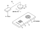
図1(A)には、金地金10が示されている。金地金10は、公証マーク11、データコードマーク12および地金番号13が設けられている。公証マーク11、データコードマーク12および地金番号13は、型押しにより金地金10の表面に凹凸を設けることで形成された回折格子であり、データコードマーク12は後述する固有の設計による回折格子を利用することで、コード化したデータを機械認識することができ、データコードマーク12をホログラム表示として視認もできる。また公証マーク11と地金番号13は回折格子でなく刻印もしくはレリーフによる模様としてもよい。
図1(A)には、金地金10が示されている。金地金10は、公証マーク11、データコードマーク12および地金番号13が設けられている。公証マーク11、データコードマーク12および地金番号13は、型押しにより金地金10の表面に凹凸を設けることで形成された回折格子であり、データコードマーク12は後述する固有の設計による回折格子を利用することで、コード化したデータを機械認識することができ、データコードマーク12をホログラム表示として視認もできる。また公証マーク11と地金番号13は回折格子でなく刻印もしくはレリーフによる模様としてもよい。
公証マーク11や地金番号13は、目視により観察される表示であり、当該金の真正を示す表示である。公証マーク11や地金番号13を回折格子とする場合、ピッチ(格子間隔)は1600~2400nmであり、深さは100~1000nmである。ピッチは、観察される角度や色と関連があり、金地金の場合は、上述した値とすることが好ましい。
図2に示すように、金は波長が600nm以上の光で高い反射率を示す。このため、金は、金色と呼ばれる独特の光沢に見える。また、公証マーク11および地金番号13を際立って視認できる様にするためには、公証マーク11および地金番号13を構成する回折格子のピッチを2000~2300nmとすることが好ましい。
データコードマーク12には、コードデータが書き込まれている。このコードデータには、金地金10の真贋判定データ、当該金のグレード、発行元、発行日、固体識別データ等が含まれる。データコードマーク12は、後述する読み取りシステムによって光学的に読み取られる。地金番号13は、目視により金地金10を識別するための固体識別番号である。
データコードマーク12を構成する回折格子は、ピッチが1000~1600nmであり、深さは200~1000nmに設定されている。ピッチを1000~1600nmとすることで、近赤外領域の光を用いてコードデータの読み取りが行われるようにしている。近赤外領域の光は金での反射率が高く、金の検出に適している。また可視光に比べ透過性も良いため、汚れや掠れに対するデータ読み取り率の低下を抑えることができる。また近赤外光は肉眼では見えないため、セキュリティ的にも適している。また光源として使用するレーザダイオードやLEDにおいて、近赤外領域の製品は入手性が良く、価格も安く、非常に適している。
またデータコードマーク間や、その周囲にダミーマークを設ける場合もある。このダミーマークは、ピッチが600~1000nm、または1600~2400nmの回折格子であり、目視ではホログラム表示として視認される。しかし回折角がデータコードマークと異なるため、読み取りの際には回折光が認識されず、データコード自体の読み取り性は低下しない。こうしたダミーマークを設けることにより、データコードマークの所在を分かりにくくすることができると同時に、ダミーマークをデザインとして使用することで意匠性を持たせることもできる。
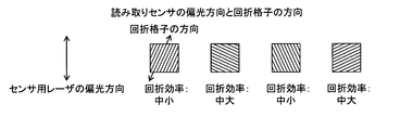
データコードマーク12を構成する回折格子は、複数設けられている。以下、この複数の回折格子の方向について説明する。図3には、データを読み取る際に照射されるレーザ光の偏光の方向と、データコードマーク12を構成する複数の回折格子の向きの関係が示されている。この例では、データコードマーク12を構成する複数の回折格子の種類が4種類であり、この4種類の回折格子の組み合わせにより、コードデータが構成されている。
図3に示すように、読み取り用に照射されるレーザ光の偏光の方向と、4種類ある回折格子の方向とが一致しないように設定されている。回折格子からの反射光の強度が最大となるのは、照射されるレーザ光の偏光方向と回折格子の方向とが直交する場合であり、当該反射光の強度が最低となるのは、照射されるレーザ光の偏光方向と回折格子の方向とが平行となる場合である。そこで、図3に示すように、読み取り用に照射されるレーザ光の偏光の方向と、4種類ある回折格子の方向とが一致しないように設定することで、コードデータの読み取りの安定性を確保している。
公証マーク11、データコードマーク12および地金番号13を構成する回折格子の断面形状としては、図4(A)に示すサインカーブ形状のものが採用される。また、当該断面形状として、データコードマークには図4(B)に示すブレーズド形状(鋸形状)を利用することもできる。また矩形波状、三角波形状でも良い。図4(B)に示すようなブレーズド形状とすることで、入射光と回折光が特定の角度になった場合、一方向だけ回折光強度は非常に高くなる。その回折光強度の特異性を利用することにより、耐偽造性および真贋判定の精度を高めることができる。
図1(B)には、データコードマークと視認用のホログラム表示とが混載された場合の例が示されている。この場合、金地金10に混載マーク14が刻印されている。混載マーク14は、データコードマーク14aと公証マーク14bにより構成されている。データコードマーク14aは、ピッチが1000~1600nmであり、深さは200~1000nmの回折格子により構成されている。公証マーク14bは、ピッチが1600~2400nm、深さが100~1000nmの回折格子により構成されている。混載することにより目視では公証マークとデータコードマークの差異は認識できないが、特定のセンサではデータコードマークを読み取ることができる。
(加工法)
公証マーク11、データコードマーク12および地金番号13を構成する回折格子を得るための方法としては、前もってエッチングなどにより回折格子を設けた型を押し付ける刻印による方法が挙げられる。この場合、前もって型および金地金を約500℃に加熱し、5t程度のプレスを用いて刻印を行う。なお型は、鉄やニッケルが適している。また刻印した際の金と型の剥離性を向上させるために、型の表面に酸化ケイ素や酸化タンタル、酸化クロム等をコーティングすると良い。
公証マーク11、データコードマーク12および地金番号13を構成する回折格子を得るための方法としては、前もってエッチングなどにより回折格子を設けた型を押し付ける刻印による方法が挙げられる。この場合、前もって型および金地金を約500℃に加熱し、5t程度のプレスを用いて刻印を行う。なお型は、鉄やニッケルが適している。また刻印した際の金と型の剥離性を向上させるために、型の表面に酸化ケイ素や酸化タンタル、酸化クロム等をコーティングすると良い。
刻印以外の方法としては、上記の型を用いて鋳造を行う方法を挙げることができる。また、当該回折格子を形成する方法として、直接エッチングやレーザ加工を用いることも可能である。
(データ読み取りシステム)
図5には、データコードマーク12を読み取るためのシステム20の一例が示されている。データ読み取りシステム20は、読み取り部21を備えている。このように金地金10もしくはデータ読み取りシステム20を所定の方向に動かして、データ読み取りを行う。図6には、読み取り部21を正面から見た様子が示されている。
図5には、データコードマーク12を読み取るためのシステム20の一例が示されている。データ読み取りシステム20は、読み取り部21を備えている。このように金地金10もしくはデータ読み取りシステム20を所定の方向に動かして、データ読み取りを行う。図6には、読み取り部21を正面から見た様子が示されている。
読み取り部21は、発光部22と受光部23を有している。発光部22は、近赤外光(波長:700~1000nm)の光を発光するレーザダイオードやLED(発光ダイオード)により構成されている。読み取り用光源が半導体レーザの場合、発する光は直線偏光となっているため、図3の様に方向を合わせてセッティングをおこなう必要がある。
発光部22は、中心にあり、発光部22の周囲に受光部23が配置されている。受光部23は、単位受光部23a~23hが周方向に沿って配置された構造を有している。単位受光部23a~23hには、赤外領域に感度を有するフォトダイオードやフォトトランジスタ等の光センサが配置されており、各センサが回折光の有無を検知する。
受光部23からの検出信号は、データ解析部25に送られる。データ解析部25は、CPU、メモリ、インターフェース回路、その他電子回路を搭載し、コンピュータとして機能する。データ解析部25は、単位受光部23a~23hからの検出信号の組み合わせに基づきに、読み取ったデータのデコードおよび読み取ったデータに基づく真贋判定を行う。
光源が直線偏光を発する形態の場合、照射光を円偏光に変換し、それをデータ読み取り光とする方法もある。データ読み取り光が直線偏光である場合、回折格子の向きとデータ読み取り光の偏光方向との関係が異なると、回折格子からの反射光の強度に違いが生じる。したがって、直線偏光のデータ読み出し光を用いた場合における異なる対象物に対する真贋判定において、データ読み出し光の偏光の方向と回折格子の向きに違いがあると、回折格子からの反射光の強度に違いが生じる問題が発生する。この問題は、判定装置における真贋判定対象物のセッティングの向きの違い等に起因して発生する。また、この問題は、複数の回折格子が配置されている場合に、回折格子毎に向きが異なる場合や向きにバラツキがある場合にも生じる。
データ読み取り光として円偏光を用いることで、回折格子の方向に起因する回折格子からの反射光の強度のバラツキを無くすことができる。このため、データの読み取り精度を高めることができる。
例えば、半導体レーザを使用する場合には、半導体レーザからの光は直線偏光であるので、光源の前に1/4波長板を配置し、直線偏光を円偏光とすることにより、円偏光のレーザ光を対象物に放射するようにする。
(データ読み取りシステムの動作)
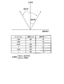
以下、一例として図1(A)の金地金10の真贋判定を行う場合を説明する。この場合、発光部22から金地金10のデータコードマーク12に向けて近赤外領域の半導体レーザ光が照射される。この際、発光部の前に1/4波長板を配置し、データコードマーク12に照射されるレーザ光を円偏光にする。データコードマーク12に照射されたレーザ光は、データコードマーク12を構成する回折格子で反射される。この際、図7に示すように、反射された光は、回折光となり、ある入射光に対してある角度をもって反射する。図7には、回折格子の式(d・sinθ=λ)より使用する波長(λ)、回折光の反射角度(θ)、回折格子のピッチ(d)の関係の一例が示されている。
以下、一例として図1(A)の金地金10の真贋判定を行う場合を説明する。この場合、発光部22から金地金10のデータコードマーク12に向けて近赤外領域の半導体レーザ光が照射される。この際、発光部の前に1/4波長板を配置し、データコードマーク12に照射されるレーザ光を円偏光にする。データコードマーク12に照射されたレーザ光は、データコードマーク12を構成する回折格子で反射される。この際、図7に示すように、反射された光は、回折光となり、ある入射光に対してある角度をもって反射する。図7には、回折格子の式(d・sinθ=λ)より使用する波長(λ)、回折光の反射角度(θ)、回折格子のピッチ(d)の関係の一例が示されている。
データコードマーク12を構成する回折格子からの反射光は、受光部23で受光される。ここで、受光部23の各単位受光部の出力の組み合わせに応じたデータが予めデータ解析部25に記憶されており、受光部23からの検出信号に基づくデコードがデータ解析部25において行われる。例えば、データコードマーク12に真贋判定用のデータが書き込まれている場合、解析部25は、受光物23で受光した反射光(回折光)に基づくデコードおよび真贋判定を行い、その結果を出力する。この例では、データコードマーク12に照射するレーザ光を円偏光に変換し、それをデータ読み出し光としているので、円偏光に変換せずに直線偏光を照射した場合に比較してデータの読み出し精度を高めることができる。
(優位性)
金地金10自体に真贋判定のためのデータが付与されるので、金地金自体10の真贋判定を確実に行える。また、データコードマーク12や14aは、刻印であり、不純物が付加されるわけではないため金地金10の純度に影響を与えない。このため、金地金10を再溶融して再加工する際、不純物を除去するためのコスト上昇や純度低下の問題が生じない。また、図5のシステムは、低コストで得ることができ、データを読み取っての判定作業も簡便に行うことができる。また、コード化されたデータを非接触で光学的に読み取ることで真贋の判定を行うので、高い精度で真贋の判定を行うことができる。また、目視でホログラム像を観察できるので、高い意匠性を得ることができる。
金地金10自体に真贋判定のためのデータが付与されるので、金地金自体10の真贋判定を確実に行える。また、データコードマーク12や14aは、刻印であり、不純物が付加されるわけではないため金地金10の純度に影響を与えない。このため、金地金10を再溶融して再加工する際、不純物を除去するためのコスト上昇や純度低下の問題が生じない。また、図5のシステムは、低コストで得ることができ、データを読み取っての判定作業も簡便に行うことができる。また、コード化されたデータを非接触で光学的に読み取ることで真贋の判定を行うので、高い精度で真贋の判定を行うことができる。また、目視でホログラム像を観察できるので、高い意匠性を得ることができる。
(その他)
本発明は、金地金以外にプラチナや銀等の貴金属に利用することできる。
本発明は、金地金以外にプラチナや銀等の貴金属に利用することできる。
本発明は、貴金属の真贋の識別を行うための技術に利用することができる。
Claims (8)
- 貴金属の表面に回折格子が設けられており、
前記回折格子により真贋判定を行うコードが構成されていることを特徴とする貴金属の真贋判定構造。 - 前記真贋判定を行うための前記回折格子が複数設けられており、データ読み取り光が直線偏光である場合に、前記複数の回折格子のそれぞれにおける当該回折格子の方向が前記データ読み取り光の偏光の方向と一致していないことを特徴とする請求項1に記載の貴金属の真贋判定構造。
- 前記コードと、前記コード以外の異なる格子構造を持つ回折格子を混載し、目視では両者を識別できないことを特徴とする請求項1または2に記載の貴金属の真贋判定構造。
- 当該貴金属が金であり、前記真贋判定を行うコードを構成する回折格子のピッチが1000~1600nmであることを特徴とする請求項1~3のいずれか一項に記載の貴金属の真贋判定構造。
- 前記回折格子が型を用いた刻印、型を用いた鋳造、エッチングまたはレーザ加工により形成されていることを特徴とする請求項1~4のいずれか一項に記載の貴金属の真贋判定構造。
- 前記回折格子の断面形状をブレーズド形状とすることを特徴とする請求項1~5のいずれか一項に記載の貴金属の真贋判定構造。
- 請求項1~6のいずれか一項に記載の前記回折格子に光を照射し、その回折光に基づいて真贋判定を行うことを特徴とする貴金属の真贋判定方法。
- 請求項1の真贋判定構造の真贋判定方法であって、
前記回折格子に円偏光を照射し、その反射光に基づいて前記真贋判定が行われることを特徴とする貴金属の真贋判定方法。
Applications Claiming Priority (2)
| Application Number | Priority Date | Filing Date | Title |
|---|---|---|---|
| JP2013-161397 | 2013-08-02 | ||
| JP2013161397A JP6278552B2 (ja) | 2013-08-02 | 2013-08-02 | 貴金属の真贋判定構造および貴金属の真贋判定方法 |
Publications (1)
| Publication Number | Publication Date |
|---|---|
| WO2015016163A1 true WO2015016163A1 (ja) | 2015-02-05 |
Family
ID=52431696
Family Applications (1)
| Application Number | Title | Priority Date | Filing Date |
|---|---|---|---|
| PCT/JP2014/069782 Ceased WO2015016163A1 (ja) | 2013-08-02 | 2014-07-28 | 貴金属の真贋判定構造および貴金属の真贋判定方法 |
Country Status (2)
| Country | Link |
|---|---|
| JP (1) | JP6278552B2 (ja) |
| WO (1) | WO2015016163A1 (ja) |
Cited By (1)
| Publication number | Priority date | Publication date | Assignee | Title |
|---|---|---|---|---|
| DE102015122831A1 (de) * | 2015-12-23 | 2017-06-29 | Münzmanufaktur Medaillen Und Münzen Gmbh | Fälschungssicherer Edelmetallbarren |
Families Citing this family (2)
| Publication number | Priority date | Publication date | Assignee | Title |
|---|---|---|---|---|
| JP6707926B2 (ja) * | 2016-03-16 | 2020-06-10 | 凸版印刷株式会社 | 識別システム、識別方法及びプログラム |
| KR102027459B1 (ko) * | 2017-02-03 | 2019-10-04 | 주식회사 더코더 | 가상 근거리 통신 지원 시스템 |
Citations (2)
| Publication number | Priority date | Publication date | Assignee | Title |
|---|---|---|---|---|
| US5754520A (en) * | 1994-12-22 | 1998-05-19 | Landis & Gyr Technology Innovation Ag | Optical data carriers and reading devices therefor |
| WO2012165193A1 (ja) * | 2011-05-31 | 2012-12-06 | 大日本印刷株式会社 | 偽造防止用粒子及びその製造方法、偽造防止用インク、偽造防止用シート、有価証券、カード |
-
2013
- 2013-08-02 JP JP2013161397A patent/JP6278552B2/ja not_active Expired - Fee Related
-
2014
- 2014-07-28 WO PCT/JP2014/069782 patent/WO2015016163A1/ja not_active Ceased
Patent Citations (2)
| Publication number | Priority date | Publication date | Assignee | Title |
|---|---|---|---|---|
| US5754520A (en) * | 1994-12-22 | 1998-05-19 | Landis & Gyr Technology Innovation Ag | Optical data carriers and reading devices therefor |
| WO2012165193A1 (ja) * | 2011-05-31 | 2012-12-06 | 大日本印刷株式会社 | 偽造防止用粒子及びその製造方法、偽造防止用インク、偽造防止用シート、有価証券、カード |
Cited By (1)
| Publication number | Priority date | Publication date | Assignee | Title |
|---|---|---|---|---|
| DE102015122831A1 (de) * | 2015-12-23 | 2017-06-29 | Münzmanufaktur Medaillen Und Münzen Gmbh | Fälschungssicherer Edelmetallbarren |
Also Published As
| Publication number | Publication date |
|---|---|
| JP2015030192A (ja) | 2015-02-16 |
| JP6278552B2 (ja) | 2018-02-14 |
Similar Documents
| Publication | Publication Date | Title |
|---|---|---|
| US8308197B2 (en) | Diffractive security element with individualized code | |
| CN1332352C (zh) | 具有衍射条型码的标签和用于这种标签的读解设备 | |
| US8408470B2 (en) | Object for authentication verification, authentication verifying chip reading device and authentication judging method | |
| US8770487B2 (en) | Information recording medium and method of reading information from information recording medium, and image detection apparatus | |
| CN101351812B (zh) | 小尺寸产品的编码标记方法和根据所述方法获得的标记产品 | |
| AU2013270023B2 (en) | Verification of documents of value having a window displaying diffractive structures | |
| JP2020509508A (ja) | セキュリティ文書の認証方法並びにセキュリティ文書、装置及びセキュリ素子 | |
| US9202328B2 (en) | Authentication verifying method, authentication verifying member and authentication verifying member producing method | |
| JPS5882372A (ja) | 書類の真偽検査装置 | |
| EP3205512A1 (en) | Optical security device | |
| JP6278552B2 (ja) | 貴金属の真贋判定構造および貴金属の真贋判定方法 | |
| US8020776B2 (en) | Multilayer element with an identification which can be read optically by a machine | |
| CN109291684B (zh) | 芯片卡模块、其制造方法、其检查方法和芯片卡 | |
| JP2012505532A (ja) | 光センサ | |
| TWI772420B (zh) | 用於鑑別物件,特別是鑑別防偽元件的方法及防偽元件 | |
| CN105163951A (zh) | 多层主体和用于产生多层主体的方法 | |
| EP3214505B1 (en) | System and methods for determining authenticity of asecurity medium includind a reflection-type volume hologram | |
| JP5274020B2 (ja) | 真贋判別可能なカード | |
| RU2435218C2 (ru) | Карта с возможностью аутентификации | |
| KR101597754B1 (ko) | 위조방지 패턴 감지장치 및 감지방법 | |
| ES2349571T3 (es) | Detección de impresión calcográfica. | |
| US9514403B2 (en) | Smart card with a security element divided between card body and module | |
| KR20100088464A (ko) | 비공개 회절 패턴이 적용된 보안 필름 | |
| KR101906480B1 (ko) | 진위판별용 보안시트 및 이를 이용한 진위판별 방법 | |
| US7076100B2 (en) | Method and apprartus thereof for detecting a hidden image in a hologram |
Legal Events
| Date | Code | Title | Description |
|---|---|---|---|
| 121 | Ep: the epo has been informed by wipo that ep was designated in this application |
Ref document number: 14831211 Country of ref document: EP Kind code of ref document: A1 |
|
| NENP | Non-entry into the national phase |
Ref country code: DE |
|
| 32PN | Ep: public notification in the ep bulletin as address of the adressee cannot be established |
Free format text: NOTING OF LOSS OF RIGHTS PURSUANT TO RULE 112(1) EPC |
|
| 122 | Ep: pct application non-entry in european phase |
Ref document number: 14831211 Country of ref document: EP Kind code of ref document: A1 |