WO2015015841A1 - Current blocking device and electricity storage device using same - Google Patents
Current blocking device and electricity storage device using same Download PDFInfo
- Publication number
- WO2015015841A1 WO2015015841A1 PCT/JP2014/059822 JP2014059822W WO2015015841A1 WO 2015015841 A1 WO2015015841 A1 WO 2015015841A1 JP 2014059822 W JP2014059822 W JP 2014059822W WO 2015015841 A1 WO2015015841 A1 WO 2015015841A1
- Authority
- WO
- WIPO (PCT)
- Prior art keywords
- plate
- contact
- case
- current
- deformation
- Prior art date
Links
Images


Classifications
-
- H—ELECTRICITY
- H01—ELECTRIC ELEMENTS
- H01M—PROCESSES OR MEANS, e.g. BATTERIES, FOR THE DIRECT CONVERSION OF CHEMICAL ENERGY INTO ELECTRICAL ENERGY
- H01M10/00—Secondary cells; Manufacture thereof
- H01M10/42—Methods or arrangements for servicing or maintenance of secondary cells or secondary half-cells
- H01M10/425—Structural combination with electronic components, e.g. electronic circuits integrated to the outside of the casing
- H01M10/4257—Smart batteries, e.g. electronic circuits inside the housing of the cells or batteries
-
- H—ELECTRICITY
- H01—ELECTRIC ELEMENTS
- H01M—PROCESSES OR MEANS, e.g. BATTERIES, FOR THE DIRECT CONVERSION OF CHEMICAL ENERGY INTO ELECTRICAL ENERGY
- H01M50/00—Constructional details or processes of manufacture of the non-active parts of electrochemical cells other than fuel cells, e.g. hybrid cells
- H01M50/50—Current conducting connections for cells or batteries
- H01M50/572—Means for preventing undesired use or discharge
- H01M50/574—Devices or arrangements for the interruption of current
- H01M50/578—Devices or arrangements for the interruption of current in response to pressure
-
- H—ELECTRICITY
- H01—ELECTRIC ELEMENTS
- H01H—ELECTRIC SWITCHES; RELAYS; SELECTORS; EMERGENCY PROTECTIVE DEVICES
- H01H35/00—Switches operated by change of a physical condition
- H01H35/24—Switches operated by change of fluid pressure, by fluid pressure waves, or by change of fluid flow
- H01H35/34—Switches operated by change of fluid pressure, by fluid pressure waves, or by change of fluid flow actuated by diaphragm
-
- H—ELECTRICITY
- H01—ELECTRIC ELEMENTS
- H01M—PROCESSES OR MEANS, e.g. BATTERIES, FOR THE DIRECT CONVERSION OF CHEMICAL ENERGY INTO ELECTRICAL ENERGY
- H01M10/00—Secondary cells; Manufacture thereof
- H01M10/42—Methods or arrangements for servicing or maintenance of secondary cells or secondary half-cells
- H01M10/4235—Safety or regulating additives or arrangements in electrodes, separators or electrolyte
-
- H—ELECTRICITY
- H01—ELECTRIC ELEMENTS
- H01M—PROCESSES OR MEANS, e.g. BATTERIES, FOR THE DIRECT CONVERSION OF CHEMICAL ENERGY INTO ELECTRICAL ENERGY
- H01M50/00—Constructional details or processes of manufacture of the non-active parts of electrochemical cells other than fuel cells, e.g. hybrid cells
- H01M50/10—Primary casings, jackets or wrappings of a single cell or a single battery
- H01M50/172—Arrangements of electric connectors penetrating the casing
- H01M50/174—Arrangements of electric connectors penetrating the casing adapted for the shape of the cells
- H01M50/176—Arrangements of electric connectors penetrating the casing adapted for the shape of the cells for prismatic or rectangular cells
-
- H—ELECTRICITY
- H01—ELECTRIC ELEMENTS
- H01M—PROCESSES OR MEANS, e.g. BATTERIES, FOR THE DIRECT CONVERSION OF CHEMICAL ENERGY INTO ELECTRICAL ENERGY
- H01M50/00—Constructional details or processes of manufacture of the non-active parts of electrochemical cells other than fuel cells, e.g. hybrid cells
- H01M50/50—Current conducting connections for cells or batteries
- H01M50/543—Terminals
- H01M50/547—Terminals characterised by the disposition of the terminals on the cells
- H01M50/55—Terminals characterised by the disposition of the terminals on the cells on the same side of the cell
-
- H—ELECTRICITY
- H01—ELECTRIC ELEMENTS
- H01M—PROCESSES OR MEANS, e.g. BATTERIES, FOR THE DIRECT CONVERSION OF CHEMICAL ENERGY INTO ELECTRICAL ENERGY
- H01M50/00—Constructional details or processes of manufacture of the non-active parts of electrochemical cells other than fuel cells, e.g. hybrid cells
- H01M50/50—Current conducting connections for cells or batteries
- H01M50/543—Terminals
- H01M50/552—Terminals characterised by their shape
- H01M50/553—Terminals adapted for prismatic, pouch or rectangular cells
-
- H—ELECTRICITY
- H01—ELECTRIC ELEMENTS
- H01M—PROCESSES OR MEANS, e.g. BATTERIES, FOR THE DIRECT CONVERSION OF CHEMICAL ENERGY INTO ELECTRICAL ENERGY
- H01M2200/00—Safety devices for primary or secondary batteries
- H01M2200/20—Pressure-sensitive devices
-
- Y—GENERAL TAGGING OF NEW TECHNOLOGICAL DEVELOPMENTS; GENERAL TAGGING OF CROSS-SECTIONAL TECHNOLOGIES SPANNING OVER SEVERAL SECTIONS OF THE IPC; TECHNICAL SUBJECTS COVERED BY FORMER USPC CROSS-REFERENCE ART COLLECTIONS [XRACs] AND DIGESTS
- Y02—TECHNOLOGIES OR APPLICATIONS FOR MITIGATION OR ADAPTATION AGAINST CLIMATE CHANGE
- Y02E—REDUCTION OF GREENHOUSE GAS [GHG] EMISSIONS, RELATED TO ENERGY GENERATION, TRANSMISSION OR DISTRIBUTION
- Y02E60/00—Enabling technologies; Technologies with a potential or indirect contribution to GHG emissions mitigation
- Y02E60/10—Energy storage using batteries
Definitions
- the second space is held at the pressure outside the case by the communication hole provided in the lid. Therefore, in overcharge etc., it can suppress that it becomes difficult to operate
- a power storage device described below can be mounted on, for example, a vehicle and can supply electric power to a motor.
- the technique disclosed in this specification is a state in which the case functions as a terminal of one polarity (for example, a negative electrode) and the terminal of the other polarity (for example, the positive electrode) is insulated from the case as in a cylindrical battery.
- the present invention can also be applied to a power storage device of a type fixed to the case.
- the electrode assembly 60 is immersed in a liquid electrolyte.
- the electrolytic solution contains a supporting salt containing a lithium salt in a solvent.
- a solvent for example, FEC (fluoroethylene carbonate) can be used.
- the supporting salt for example, LiPF6 (lithium hexafluorophosphate) can be used.
- the electrolyte contains an aromatic monomer additive. When an overvoltage is applied to the electrode assembly 60, the monomer additive contained in the electrolyte is polymerized to generate hydrogen gas. Due to the generation of the hydrogen gas, the pressure in the internal space 25 of the case 1 increases.
- connection member 13 of the energization plate 4 is electrically connected to the electrode assembly 60 (see FIG. 1) disposed inside the case 1.
- a first contact portion 6 that comes into contact with the contact plate 5 is provided at the center of the energization plate 4.
- a second contact portion 23 that comes into contact with the energizing plate 4 is provided at the center of the contact plate 5.
- the outer peripheral portion of the contact plate 5 is electrically connected to the main body portion 41 of the lid body 40.
- the upper end portion of the cylindrical portion 42 of the lid body 40 is the negative electrode terminal 19. Thereby, a series energization path from the electrode assembly 60 to the negative electrode terminal 19 is formed.
- the protrusion 12 prevents the energization plate 4 and the contact plate 5 from re-contacting.
- transformation board 3 is not contacting other components other than the outer peripheral part being fixed to the supporting member 11. FIG. Therefore, the deformable plate 3 operates stably by the internal pressure of the case 1. Further, when the projections 12 provided on the deformation plate 3 collide with the energizing plate 4, an impact force is applied to the energizing plate 4. Even if the breaking load of the contact portions 6 and 23 varies due to the impact force, the contact portion 6 can be reliably broken.
Abstract
This current blocking device (2) is provided with: a deformation plate (3); and a contact plate (5) and a current-carrying plate (4), which constitute a current-carrying path. The current-carrying plate (4) is arranged so as to be sandwiched between the deformation plate (3) and the contact plate (5). The current-carrying plate (4) comprises a first contact part (6) that comes into contact with the contact plate (5). The contact plate (5) comprises a second contact part (23) that comes into contact with the first contact part (6). A surface of the deformation plate (3), said surface being on the reverse side of the surface facing contact plate (5), faces a first space (25) which is held at a pressure that is equal to the internal pressure of the case, and the surface of the deformation plate (3) facing contact plate (5) faces a second space (26) which is held at a pressure that is equal to the pressure of the outside of the case. In cases where the internal pressure is increased, the deformation plate (3) is deformed toward the contact plate (5) so that the second contact part (23) is separated from the current-carrying plate (4).
Description
本明細書は電流遮断装置及びそれを用いた蓄電装置に関する技術を開示する。
This specification discloses a technology relating to a current interrupt device and a power storage device using the current interrupt device.
リチウムイオン電池、ニッケル水素電池、その他の二次電池(蓄電池)等の蓄電装置は、車両搭載用電源、あるいはパソコンおよび携帯端末の電源として重要性が高まっている。特に、リチウムイオン電池は、車両搭載用の高出力電源として用いることが期待されている。リチウムイオン電池は、軽量でありながら高いエネルギー密度が得られる。二次電池の典型的な構造として、ケース内に電極組立体及び電解質が収容されており、そのケースを密閉した密閉構造の電池(密閉型電池)が挙げられる。
Power storage devices such as lithium ion batteries, nickel metal hydride batteries, and other secondary batteries (storage batteries) are becoming increasingly important as on-vehicle power sources or personal computers and portable terminals. In particular, the lithium ion battery is expected to be used as a high output power source for mounting on a vehicle. Lithium ion batteries are lightweight and can provide a high energy density. A typical structure of a secondary battery includes a battery (sealed battery) having a sealed structure in which an electrode assembly and an electrolyte are housed in a case and the case is sealed.
上記の電池を充電するときに、電池に不具合が生じていたり、充電装置が誤作動したりする場合に、電池に通常以上の電流が流れることがある。その結果、電池が、過充電状態になることがある。電池に過充電状態等の異常が生じた場合、密閉されたケース内でガスが発生することがある。ケース内部の圧力(内圧)が上昇し、ガスの圧力によって電池(ケース)が膨らんだり、ケースが破損したりすることが起こり得る。このような不具合の対策として、電流遮断装置を備えた電池が提案されている。電流遮断装置は、密閉されたケースの内圧が所定内圧まで上昇すると、ケースに収容された電極組立体と、ケースの外に露出している電極端子との間の通電経路を遮断し電池の安全性を確保する(例えば、特許文献1(日本国特開平6-215746号公報)、特許文献2(日本国特開平7-254401号公報)、特許文献3(日本国特開平9-129214号公報)、特許文献4(日本国特開平10-233199号公報)参照)。
When charging the above battery, if the battery malfunctions or the charging device malfunctions, the current may flow more than normal. As a result, the battery may be overcharged. When an abnormality such as an overcharged state occurs in the battery, gas may be generated in the sealed case. The pressure inside the case (internal pressure) increases, and the battery (case) may swell or the case may be damaged by the gas pressure. As a countermeasure against such a problem, a battery including a current interrupt device has been proposed. When the internal pressure of the sealed case rises to a predetermined internal pressure, the current interrupt device cuts off the energization path between the electrode assembly housed in the case and the electrode terminal exposed outside the case, thereby (For example, Patent Document 1 (Japanese Patent Laid-Open No. 6-215746), Patent Document 2 (Japanese Patent Laid-Open No. 7-254401), Patent Document 3 (Japanese Patent Laid-Open No. 9-129214) ), Patent Document 4 (Japanese Patent Laid-Open No. 10-233199).
図12、図13を参照し、従来の電流遮断装置について説明する。電流遮断装置50は、密閉型の二次電池のケースに取り付けられている。図12に示すように、電流遮断装置50は、封口蓋体52、反転板53及びリード取付板54を備えている。封口蓋体52は、導電性を有しており、外部端子51に接続されている。反転板53は、導電性を有しており、封口蓋体52の内側に配置されている。リード取付板54は、導電性を有しており、反転板53の内側に配置されている。リード取付板54は、金属製であり、反転板53の中央部分(接点部分)56と固着している。リード取付板54には通気孔55が形成されており、電池の内圧が反転板53に作用するようになっている。矢印57は、電池が通常状態のときの通電経路を示している。電池が通常状態のときは、電流は、リード取付板54、反転板53及び封口蓋体52を経由して、外部端子51に直列に通じる。なお、リード取付板54の外周を、支持部材58が支持している。支持部材58は、絶縁性の材料で形成されている。
A conventional current interrupting device will be described with reference to FIGS. The current interrupt device 50 is attached to a case of a sealed secondary battery. As shown in FIG. 12, the current interrupt device 50 includes a sealing lid 52, a reversing plate 53, and a lead attachment plate 54. The sealing lid 52 has conductivity and is connected to the external terminal 51. The inversion plate 53 has conductivity and is disposed inside the sealing lid body 52. The lead mounting plate 54 has conductivity and is disposed inside the reversing plate 53. The lead mounting plate 54 is made of metal, and is fixed to the central portion (contact portion) 56 of the reversing plate 53. A vent hole 55 is formed in the lead mounting plate 54 so that the internal pressure of the battery acts on the reversing plate 53. An arrow 57 indicates an energization path when the battery is in a normal state. When the battery is in a normal state, the current passes in series with the external terminal 51 via the lead attachment plate 54, the reverse plate 53, and the sealing lid body 52. A support member 58 supports the outer periphery of the lead mounting plate 54. The support member 58 is made of an insulating material.
電池が過充電等の状態になると、密閉されたケースの内部でガスが発生し、ケースの内圧が上昇する。このとき、図13に示すように、ケースの内圧が、リード取付板54の通気孔55を通じて反転板53に作用する。反転板53の中央部分(接点部分)56の固着部が破断し、反転板53が上方に反転する。通電経路57が破断され、電流が遮断される。
When the battery is overcharged, gas is generated inside the sealed case and the internal pressure of the case increases. At this time, as shown in FIG. 13, the internal pressure of the case acts on the reversal plate 53 through the vent hole 55 of the lead mounting plate 54. The fixing portion of the central portion (contact portion) 56 of the reversing plate 53 is broken, and the reversing plate 53 is reversed upward. The energization path 57 is broken and the current is interrupted.
上記した従来の電流遮断装置では、リード取付板54と反転板53との接点部56が、電解液雰囲気中に存在する。そのため、接点部56が電解液や周囲の環境により劣化し、電流遮断装置の信頼性が低下することが起こり得る。本出願人は、上記課題を解決するための技術を2012年4月12日に出願された日本国特許出願第2012-090992号及び2012年4月12日に出願された日本国特許出願第2012-090630号において提供した。すなわち、これらの特許出願は、電流遮断装置の接点部の劣化により信頼性が低下することを防止することができる技術を提供している。また、これらの特許出願は、本件の特許出願の時点で未公開である。なお、その技術の詳細については、本明細書の実施例にて詳しく説明する。
In the above-described conventional current interrupting device, the contact portion 56 between the lead mounting plate 54 and the reversing plate 53 exists in the electrolyte atmosphere. For this reason, the contact portion 56 may be deteriorated by the electrolytic solution or the surrounding environment, and the reliability of the current interrupt device may be reduced. The present applicant has applied the Japanese patent application No. 2012-090992 filed on April 12, 2012 and the Japanese patent application No. 2012 filed on April 12, 2012, for techniques for solving the above problems. -090630. That is, these patent applications provide a technique capable of preventing the reliability from being lowered due to the deterioration of the contact portion of the current interrupt device. These patent applications have not been published at the time of this patent application. The details of the technology will be described in detail in Examples of the present specification.
本明細書は、日本国特許出願第2012-090992号及び日本国特許出願第2012-090630号の技術をさらに改良した技術を提供することを目的とする。具体的には、ケースの内圧が所定レベルを超えて上昇した際に通電経路を遮断する動作の確実性をより一層高める技術を提供する。
This specification aims to provide a technique obtained by further improving the techniques of Japanese Patent Application No. 2012-090992 and Japanese Patent Application No. 2012-090630. Specifically, there is provided a technique for further enhancing the certainty of the operation of cutting off the energization path when the internal pressure of the case rises above a predetermined level.
(基本構造及び技術的特徴)
本明細書で開示する電流遮断装置は、以下の基本構造及び技術的特徴を備えている。(1)電流遮断装置の内部が、ケース内の雰囲気(電流遮断装置の外部)からシールされている。(2)ケースの内圧が上昇すると、電流遮断装置の内部と電流遮断装置の外部との圧力差によって変形板が反転する。(3)上記したように、電流遮断装置の内部は、ケース内の雰囲気からシールされている。そのため、通電経路が破断したときにアークが発生しても、水素ガスが発生しているケース内に影響を及ぼさない。蓄電装置の安全性を高くすることができる。(4)変形板は、ケース内の圧力を受圧する面とは反対側の面に外気の圧力を受けている。
(解決するための手段)
本明細書が開示する電流遮断装置は、蓄電装置に使用される電流遮断装置である。その電流遮断装置は、正極及び負極を備える電極組立体と正負いずれかの電極端子とを電気的に接続する。その電流遮断装置は、電極組立体を収容する密閉された蓄電装置のケースの内圧が所定レベルを超えて上昇した際に電極組立体と電極端子との直列な通電経路を遮断する。その電流遮断装置は、内圧が所定レベルを超えて上昇した際に変形する変形板を備えている。その電流遮断装置は、電極組立体、及び電極端子と電気的に接続された状態で通電経路を構成する接点板及び通電板を備えている。通電板は、変形板と接点板に挟まれるように配置されている。通電板は、接点板と接触する第1接点部を含んでいる。接点板は、第1接点部と接触する第2接点部を含んでいる。変形板は、接点板とは反対側の面が、内圧と同じ圧力に保持されている第1空間に面している。変形板は、接点板に対向している面が、ケースの外側の圧力に保持されている第2空間に面している。変形板には、第1接点部もしくは第2接点部に接触する当接部が形成されている。その電流遮断装置は、内圧が所定レベルを超えて上昇した際に、当接部が接点板側へ移動するように変形板が変形することにより、第1接点部及び第2接点部のうち、少なくとも第2接点部が通電板と分離可能である。 (Basic structure and technical features)
The current interrupting device disclosed in the present specification has the following basic structure and technical features. (1) The inside of the current interrupt device is sealed from the atmosphere in the case (outside of the current interrupt device). (2) When the internal pressure of the case rises, the deformed plate is inverted due to the pressure difference between the inside of the current interrupt device and the outside of the current interrupt device. (3) As described above, the inside of the current interrupting device is sealed from the atmosphere in the case. Therefore, even if an arc is generated when the energization path is broken, it does not affect the case where hydrogen gas is generated. The safety of the power storage device can be increased. (4) The deformation plate receives the pressure of the outside air on the surface opposite to the surface receiving the pressure in the case.
(Means for solving)
The current interrupt device disclosed in the present specification is a current interrupt device used for a power storage device. The current interrupting device electrically connects an electrode assembly including a positive electrode and a negative electrode and one of positive and negative electrode terminals. The current interrupting device interrupts the series current path between the electrode assembly and the electrode terminal when the internal pressure of the case of the sealed power storage device that houses the electrode assembly rises above a predetermined level. The current interrupt device includes a deformable plate that deforms when the internal pressure rises above a predetermined level. The current interrupting device includes an electrode assembly and a contact plate and an energizing plate that constitute an energizing path in a state of being electrically connected to the electrode terminal. The energization plate is disposed so as to be sandwiched between the deformation plate and the contact plate. The energization plate includes a first contact portion that contacts the contact plate. The contact plate includes a second contact portion that contacts the first contact portion. The deformation plate faces the first space where the surface opposite to the contact plate is held at the same pressure as the internal pressure. The surface of the deformable plate that faces the contact plate faces the second space that is held at the pressure outside the case. The deforming plate is formed with a contact portion that contacts the first contact portion or the second contact portion. The current interrupting device is configured such that when the internal pressure rises above a predetermined level, the deforming plate is deformed so that the contact portion moves toward the contact plate side, and thus, among the first contact portion and the second contact portion, At least the second contact portion is separable from the energizing plate.
上記の電流遮断装置では、変形板により、通電板と接点板との接点部が、電解液が存在する雰囲気から遮断される。そのため、接点部が、電解液や周囲の環境の影響を受けて劣化することを防止することができる。また、通電経路が破断したときにアーク(火花)が発生しても、水素ガスが発生しているケース内に影響を及ぼさない。さらに、上記電流遮断装置では、変形板は、外周の固定部にのみ接触している。そのため、変形板は、従来技術のように溶接強度の影響を受けることがなく、内部圧力によって安定して作動する。
In the above current interrupting device, the contact portion between the energizing plate and the contact plate is interrupted by the deformable plate from the atmosphere in which the electrolyte exists. Therefore, it is possible to prevent the contact portion from being deteriorated due to the influence of the electrolytic solution or the surrounding environment. Further, even if an arc (spark) is generated when the energization path is broken, the case where hydrogen gas is generated is not affected. Further, in the current interrupt device, the deformable plate is in contact only with the outer peripheral fixed portion. Therefore, the deformation plate is not affected by the welding strength as in the prior art, and operates stably by the internal pressure.
また、上記の電流遮断装置では、変形板に対して接点板側に位置する空間である第2空間が外気と連通している。このため、例えば、ケース内の空間と第2空間との間の気密性が低下する等して、ケース内の空間から第2空間へとガスが流入した場合等にも、第2空間の圧力が上昇することを抑制することができる。その結果、第2空間の圧力を一定に保ち易く、過充電等によりケース内の空間の圧力が上昇した際に第1空間と第2空間の圧力差を生じさせ易い。これにより、過充電等の場合に、第1空間と第2空間の圧力差が不足することによって電流遮断装置が作動し難くなることを抑制することができる。
In the current interrupt device, the second space, which is a space located on the contact plate side with respect to the deformation plate, communicates with the outside air. For this reason, for example, even when gas flows into the second space from the space in the case due to a decrease in airtightness between the space in the case and the second space, the pressure in the second space Can be prevented from rising. As a result, it is easy to keep the pressure in the second space constant, and it is easy to cause a pressure difference between the first space and the second space when the pressure in the space in the case rises due to overcharging or the like. Thereby, in overcharge etc., it can suppress that it becomes difficult to operate | move an electric current interruption apparatus because the pressure difference of 1st space and 2nd space runs short.
本明細書が開示する電流遮断装置は、接点部の劣化を抑制することができ、かつ、電流遮断装置が作動し難くなることを抑制することができる。
The current interrupt device disclosed in the present specification can suppress deterioration of the contact portion, and can suppress the current interrupt device from becoming difficult to operate.
以下、本明細書で開示する実施例の技術的特徴の幾つかを記す。なお、以下に記す事項は、各々単独で技術的な有用性を有している。
Hereinafter, some of the technical features of the embodiments disclosed in this specification will be described. The items described below have technical usefulness independently.
(特徴1) 本明細書が開示する電流遮断装置は、典型的には、蓄電装置のケースの壁に形成された開口部に取り付けられる。その電流遮断装置は、一方が開口部を通じてケースの外側に露出しているとともに他方が電流遮断装置の筐体の一部を構成しており、接点板と導通している導電性の蓋体を備えていてもよい。蓋体は、その一方から他方まで貫通する連通孔が設けられていてもよい。第2空間は、連通孔を通じてケースの外側の圧力に保持されている。
(Feature 1) The current interrupting device disclosed in this specification is typically attached to an opening formed in the wall of the case of the power storage device. One of the current interrupting devices is exposed to the outside of the case through the opening, and the other constitutes a part of the casing of the current interrupting device, and a conductive lid that is electrically connected to the contact plate is provided. You may have. The lid may be provided with a communication hole penetrating from one side to the other. The second space is held at a pressure outside the case through the communication hole.
上記の電流遮断装置では、蓋体に設けられた連通孔によって、第2空間がケースの外側の圧力に保持される。これにより、過充電等の場合に、第1空間と第2空間の圧力差が不足することによって電流遮断装置が作動し難くなることを抑制することができる。
In the above current interrupting device, the second space is held at the pressure outside the case by the communication hole provided in the lid. Thereby, in overcharge etc., it can suppress that it becomes difficult to operate | move an electric current interruption apparatus because the pressure difference of 1st space and 2nd space runs short.
(特徴2) 本明細書が開示する電流遮断装置では、蓄電装置のケースの外側に露出している蓋体の一方に、外部の装置へ電力を供給する導電部材を接続する接続部を有していてもよい。導電部材とは、典型的には電源ケーブルである。
(Characteristic 2) In the current interrupt device disclosed in this specification, one of the lids exposed to the outside of the case of the power storage device has a connection portion that connects a conductive member that supplies power to an external device. It may be. The conductive member is typically a power cable.
接続部は、電極端子に相当する。つまり、上記の電流遮断装置では、電流遮断装置と電極端子とが一体となっている。このため、電流遮断装置と電極端子との間に別途配線等を設ける必要が無い。これにより、通電経路の電気抵抗を低減することができる。
The connection part corresponds to an electrode terminal. That is, in the current interrupt device, the current interrupt device and the electrode terminal are integrated. For this reason, it is not necessary to separately provide wiring or the like between the current interrupt device and the electrode terminal. Thereby, the electrical resistance of an energization path can be reduced.
(特徴3) 本明細書が開示する電流遮断装置では、接続部は、蓋体の連通孔の内面に形成されたメネジを有していてもよい。メネジは、上記した導電部材を固定するために設けられる。
(Characteristic 3) In the current interrupt device disclosed in the present specification, the connection portion may have a female screw formed on the inner surface of the communication hole of the lid. The female screw is provided to fix the above-described conductive member.
上記の電流遮断装置では、蓋体の一方に開口している連通孔にメネジが形成されている。このメネジに例えばボルトを係合させることができる。ボルトの頭と蓋体の一方との間で、外部の装置へ電力を供給するケーブル(導電部材)を挟んで固定することができる。すなわち、上記の電流遮断装置では、第2空間とケースの壁の外側の空間とを連通させている蓋体の連通孔を利用して外部の装置を接続することができる。従って、導電部材を接続する為の取付け穴等を別途設ける必要が無い。これにより、電流遮断装置の製造コストを低減することができる。
In the above current interrupting device, a female screw is formed in the communication hole opened on one side of the lid. For example, a bolt can be engaged with the female screw. A cable (conductive member) for supplying electric power to an external device can be sandwiched and fixed between the head of the bolt and one of the lids. That is, in the above current interrupting device, an external device can be connected by using the communication hole of the lid that communicates the second space and the space outside the wall of the case. Therefore, there is no need to separately provide a mounting hole or the like for connecting the conductive member. Thereby, the manufacturing cost of an electric current interruption apparatus can be reduced.
(特徴4) 本明細書が開示する電流遮断装置では、蓄電装置のケースの外側に露出している蓋体の一方の側面にはオネジが形成されていてもよい。その電流遮断装置は、オネジと係合する固定部材を有していてもよい。その電流遮断装置は、オネジと係合する固定部材と、蓋体のケースの内側に位置する部位とでケースの壁を挟み込んでケースに固定されてもよい。
(Characteristic 4) In the current interrupt device disclosed in this specification, a male screw may be formed on one side surface of the lid that is exposed to the outside of the case of the power storage device. The current interrupt device may have a fixing member that engages with the male screw. The current interrupting device may be fixed to the case by sandwiching the wall of the case between a fixing member that engages with the male screw and a portion that is located inside the case of the lid.
上記の電流遮断装置では、蓋体の外側に露出している部位にオネジが形成されている。このため、オネジに固定部材のメネジを係合させることによって、電流遮断装置をケースに取り付けることができる。これにより、上記の電流遮断装置では、蓋体をケースの外側の空間に露出させることにより第2空間と外気を連通させつつ、電流遮断装置をケースに取り付けることができる。
In the above current interrupting device, a male screw is formed at a portion exposed to the outside of the lid. For this reason, the current interrupting device can be attached to the case by engaging the female screw of the fixing member with the male screw. Thereby, in said electric current interruption apparatus, an electric current interruption apparatus can be attached to a case, connecting a 2nd space and external air by exposing a cover body to the space outside a case.
(特徴5) 本明細書が開示する電流遮断装置では、変形板の中央部は、接点板の側に向けて突出する絶縁性の突起が設けられ、突起に当接部を有していてもよい。
(Characteristic 5) In the current interrupt device disclosed in the present specification, the central portion of the deformable plate is provided with an insulating protrusion that protrudes toward the contact plate, and the protrusion has a contact portion. Good.
上記の電流遮断装置では、通電経路の破断後は、絶縁性の突起により通電板と接点板との再接触を防止することができる。
In the above current interrupting device, after the energization path is broken, the contact between the energization plate and the contact plate can be prevented by the insulating protrusion.
(特徴6) 本明細書が開示する電流遮断装置は、変形板と通電板との間に配置される当接部材、及び絶縁性を有するキャップを有していてもよい。絶縁性の突起が、当接部材及びキャップによって構成されていてもよい。当接部材は、変形板の通電板側の面の中央部に配置されていてもよい。キャップは、当接部材を覆っているキャップ部と、キャップ部の位置を、変形板と通電板とを結ぶ方向に直交する平面内において規制しているガイド部とを有していてもよい。
(Characteristic 6) The current interrupting device disclosed in the present specification may include a contact member disposed between the deforming plate and the energizing plate, and an insulating cap. The insulating protrusion may be constituted by the contact member and the cap. The abutting member may be disposed at the center of the surface of the deformable plate on the current-carrying plate side. The cap may include a cap portion that covers the contact member, and a guide portion that regulates the position of the cap portion in a plane orthogonal to the direction connecting the deforming plate and the current-carrying plate.
上記の電流遮断装置では、当接部材が変形板の中央部に位置し、かつ、絶縁性を有するキャップが当接部材を覆っている。また、キャップは、変形板上での当接部材の位置を規制している。これにより、簡単な構成によって変形板の中央部に絶縁性の突起を設けることができる。
In the above current interrupting device, the contact member is located at the center of the deformation plate, and the cap having insulation properties covers the contact member. The cap restricts the position of the contact member on the deformation plate. Thereby, an insulating protrusion can be provided in the center part of a deformation board by simple structure.
以下、本明細書で開示する電流遮断装置及び蓄電装置の実施例について説明する。なお、本明細書で開示する蓄電装置では、電流遮断装置以外の構成は様々なものを使用することができる。また、以下に説明する蓄電装置は、例えば車両に搭載され、モータに電力を供給することができる。
Hereinafter, examples of the current interrupting device and the power storage device disclosed in this specification will be described. Note that in the power storage device disclosed in this specification, various configurations other than the current interrupt device can be used. In addition, a power storage device described below can be mounted on, for example, a vehicle and can supply electric power to a motor.
蓄電装置の一例として、密閉型の二次電池、密閉型のキャパシタ等が挙げられる。二次電池の一例として、比較的高容量で大電流の充放電が行われる種類の電池、例えば、リチウムイオン電池、ニッケル水素電池、ニッケルカドミウム電池、鉛蓄電池等の二次電池が挙げられる。なお、以下の説明では、リチウムイオン電池について説明する。二次電池の電極組立体の一例として、セパレータを介して対向する電極対(正極電極及び負極電極)を有するセルが複数積層された積層タイプの電極組立体、セパレータを介して対向する電極対を有するシート状のセルが渦巻状に加工された捲回型の電極組立体が挙げられる。なお、以下の説明では、正極端子と負極端子の双方がケースの一方向に露出している蓄電装置について説明する。しかしながら、本明細書で開示する技術は、円筒型の電池のように、ケースが一方の極性(例えば負極)の端子として機能し、他方の極性(例えば正極)の端子がケースから絶縁された状態でケースに固定されているタイプの蓄電装置等にも適用することができる。
Examples of power storage devices include sealed secondary batteries and sealed capacitors. As an example of a secondary battery, a secondary battery such as a lithium ion battery, a nickel hydride battery, a nickel cadmium battery, or a lead storage battery can be cited as a type of battery that is charged and discharged with a relatively high capacity and a large current. In the following description, a lithium ion battery will be described. As an example of an electrode assembly of a secondary battery, a stacked type electrode assembly in which a plurality of cells having electrode pairs (positive electrode and negative electrode) opposed via a separator are stacked, and an electrode pair opposed via a separator Examples thereof include a wound electrode assembly in which a sheet-like cell having a spiral shape is processed. In the following description, a power storage device in which both the positive electrode terminal and the negative electrode terminal are exposed in one direction of the case will be described. However, the technique disclosed in this specification is a state in which the case functions as a terminal of one polarity (for example, a negative electrode) and the terminal of the other polarity (for example, the positive electrode) is insulated from the case as in a cylindrical battery. The present invention can also be applied to a power storage device of a type fixed to the case.
図1に示すように、蓄電装置100は、ケース1と、電極組立体60と、負極端子19と、正極端子119と、電流遮断装置2を備えている。ケース1は、矩形箱状の本体部分62と、本体部分62を閉塞する矩形平板状の蓋部分63を備えている。本体部分62及び蓋部分63は、金属製(例えば、ステンレス、アルミニウム)である。以下の説明では、本体部分62及び蓋部分63を、単にケース1と称することがある。ケース1の内部の空間25には、正極電極及び負極電極を備える電極組立体60が収容されている。ケース1と電極組立体60は、絶縁シート61によって絶縁されている。正極タブ65が、正極電極に固定されている。負極タブ67が、負極電極に固定されている。
As shown in FIG. 1, the power storage device 100 includes a case 1, an electrode assembly 60, a negative electrode terminal 19, a positive electrode terminal 119, and a current interrupt device 2. The case 1 includes a rectangular box-shaped main body portion 62 and a rectangular flat plate-shaped lid portion 63 that closes the main body portion 62. The main body portion 62 and the lid portion 63 are made of metal (for example, stainless steel or aluminum). In the following description, the main body portion 62 and the lid portion 63 may be simply referred to as the case 1. An electrode assembly 60 including a positive electrode and a negative electrode is accommodated in the space 25 inside the case 1. Case 1 and electrode assembly 60 are insulated by insulating sheet 61. A positive electrode tab 65 is fixed to the positive electrode. A negative electrode tab 67 is fixed to the negative electrode.
負極端子19及び正極端子119が、ケース1(蓋部分63)に固定されている。図示は省略するが、負極端子19とケース1、及び正極端子119とケース1との間は、絶縁シート等により絶縁されている。負極端子19は、電流遮断装置2、負極リード68を介して、負極タブ67(負極電極)に電気的に接続している。電流遮断装置2の詳細は後述する。なお、電流遮断装置2と負極リード68は、導電性を有する接続部材13によって接続されている。正極端子119は、正極リード64を介して正極タブ65(正極電極)に電気的に接続している。負極リード68及び正極リード64は、ケース1(蓋部分63)に取り付けられている絶縁シート66によって、ケース1と絶縁されている。なお、本実施例の蓄電装置100では、負極端子19と電流遮断装置2とが一体化された構成となっている(後に詳しく説明する)。
The negative electrode terminal 19 and the positive electrode terminal 119 are fixed to the case 1 (lid portion 63). Although illustration is omitted, the negative electrode terminal 19 and the case 1 and the positive electrode terminal 119 and the case 1 are insulated by an insulating sheet or the like. The negative electrode terminal 19 is electrically connected to the negative electrode tab 67 (negative electrode) via the current interrupt device 2 and the negative electrode lead 68. Details of the current interrupt device 2 will be described later. In addition, the electric current interruption apparatus 2 and the negative electrode lead 68 are connected by the connection member 13 which has electroconductivity. The positive terminal 119 is electrically connected to the positive tab 65 (positive electrode) via the positive lead 64. The negative electrode lead 68 and the positive electrode lead 64 are insulated from the case 1 by an insulating sheet 66 attached to the case 1 (lid portion 63). In addition, in the electrical storage apparatus 100 of a present Example, the negative electrode terminal 19 and the electric current interruption apparatus 2 are the structures integrated (it demonstrates in detail later).
電極組立体60は、液状の電解液に浸漬されている。電解液は、溶媒中に、リチウム塩を含む支持塩を含有している。溶媒としては、例えばFEC(フルオロエチカーボネート)が使用できる。支持塩としては、例えば、LiPF6(六フッ化リン酸リチウム)が使用できる。電解質には、芳香族系のモノマー添加剤が含まれている。電極組立体60に過電圧が加わると、電解質に含まれるモノマー添加剤が重合し、水素ガスが発生する。この水素ガスの発生によって、ケース1の内部空間25の圧力が上昇する。
The electrode assembly 60 is immersed in a liquid electrolyte. The electrolytic solution contains a supporting salt containing a lithium salt in a solvent. As the solvent, for example, FEC (fluoroethylene carbonate) can be used. As the supporting salt, for example, LiPF6 (lithium hexafluorophosphate) can be used. The electrolyte contains an aromatic monomer additive. When an overvoltage is applied to the electrode assembly 60, the monomer additive contained in the electrolyte is polymerized to generate hydrogen gas. Due to the generation of the hydrogen gas, the pressure in the internal space 25 of the case 1 increases.
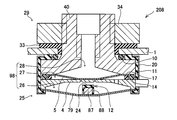
図2及び図3を参照し、電流遮断装置2について説明する。なお、図2、3では、正極電極及び負極電極を備える電極組立体60(図1を参照)の図示を省略している。電極組立体60は、図2、3の下方に配置されている。電流遮断装置2は、電極組立体60と負極端子19とを電気的に接続する。電流遮断装置2は、電極組立体60が収容されているケース1の内部とケース1の外部とのガスの流通を阻止する。電流遮断装置2は、ケース1内の内圧が所定レベルを超えて上昇したときに、電極組立体60と負極端子19との直列な通電経路を遮断する。
The current interrupting device 2 will be described with reference to FIGS. 2 and 3, the electrode assembly 60 (see FIG. 1) including the positive electrode and the negative electrode is not shown. The electrode assembly 60 is disposed below the FIGS. The current interrupt device 2 electrically connects the electrode assembly 60 and the negative terminal 19. The current interrupt device 2 prevents gas from flowing between the inside of the case 1 in which the electrode assembly 60 is accommodated and the outside of the case 1. When the internal pressure in the case 1 rises above a predetermined level, the current interrupt device 2 interrupts the series energization path between the electrode assembly 60 and the negative electrode terminal 19.
上記した「所定レベルの内圧」とは、蓄電装置100が過充電(過電圧)状態や過昇温状態(活物質の熱暴走温度)となったときのケース1内の内圧を意味する。「所定レベルの内圧」は、蓄電装置100の容量、出力電圧等の条件により設定される。
The above-mentioned “predetermined level of internal pressure” means the internal pressure in case 1 when power storage device 100 is in an overcharge (overvoltage) state or an overheated state (thermal runaway temperature of the active material). The “predetermined level of internal pressure” is set according to conditions such as the capacity of the power storage device 100 and the output voltage.
電流遮断装置2は、蓄電装置100のケース1内部に配置されており、ケース1の内部(電流遮断装置2の外部)のガスが電流遮断装置2の内部空間98(後に詳しく説明する)に流通しないようにシールされている。なお、電流遮断装置2をケース1に取付けるための構成については、後に詳述する。電流遮断装置2の構造を、蓄電装置100のケース1の内部(図2の下方)からケース1の外側(図2の上方)に向けて順に説明する。電流遮断装置2は、受圧部22を有する変形板3と、通電板4と、接点板5を備えている。変形板3は、変形可能であり、ガスの流通を阻止する。変形板3の受圧部22は、ケース1内の内圧を受けるようになっている。通電板4は、電極組立体60と電気的に接続されている。通電板4は導電性の金属で作られており、その略中央に、溝(破断溝16)が環状に設けられている。破断溝16で囲まれた部分を第1接点部6と称する。接点板5も導電性の金属で作られており、その一部が第1接点部6と接触している。接点板5において第1接点部6と接触している部位を第2接点部23と称する。変形板3は、電流遮断装置2の外側部分に配置され、電流遮断装置2の外面を形成している。通電板4、接点板5は、夫々変形板3の内側に配置されている。
The current interrupt device 2 is disposed inside the case 1 of the power storage device 100, and the gas inside the case 1 (outside the current interrupt device 2) flows into the internal space 98 (described in detail later) of the current interrupt device 2. Not sealed. The configuration for attaching the current interrupt device 2 to the case 1 will be described in detail later. The structure of the current interrupt device 2 will be described in order from the inside of the case 1 of the power storage device 100 (downward in FIG. 2) to the outside of the case 1 (upward in FIG. 2). The current interrupting device 2 includes a deformation plate 3 having a pressure receiving portion 22, a current supply plate 4, and a contact plate 5. The deformable plate 3 is deformable and prevents the gas flow. The pressure receiving portion 22 of the deformable plate 3 receives the internal pressure in the case 1. The energization plate 4 is electrically connected to the electrode assembly 60. The energizing plate 4 is made of a conductive metal, and a groove (breaking groove 16) is provided in an annular shape at the approximate center. A portion surrounded by the breaking groove 16 is referred to as a first contact portion 6. The contact plate 5 is also made of a conductive metal, and a part of the contact plate 5 is in contact with the first contact portion 6. A portion of the contact plate 5 that is in contact with the first contact portion 6 is referred to as a second contact portion 23. The deformation plate 3 is disposed on the outer portion of the current interrupt device 2 and forms the outer surface of the current interrupt device 2. The energizing plate 4 and the contact plate 5 are disposed inside the deformation plate 3, respectively.
電流遮断装置2では、通電板4に設けられている第1接点部6の第2接点部23と接触する側の反対側(図2の下方)が、変形板3と接触可能である。通電板4に設けられた破断溝16は、第1接点部6が所定の荷重を受けたときに溝に沿って通電板4が破断するようになっている。破断溝16にて通電板4が破断することにより、第1接点部6は、通電板4から分離する。電流遮断装置2では、変形板3によって、通電板4と接点板5との接点部6、23が、電解液が存在する雰囲気から遮断されている。そのため、接点部6、23は、電解液や周囲の環境によって劣化することが防止される。また、通電経路が破断したときにアーク(火花)が発生しても、水素ガスが発生している蓄電装置100のケース1内に影響を及ぼさない。
In the current interrupting device 2, the opposite side (lower side in FIG. 2) of the first contact portion 6 provided on the energizing plate 4 to the side in contact with the second contact portion 23 can contact the deformable plate 3. The breaking groove 16 provided in the energizing plate 4 is configured so that the energizing plate 4 is broken along the groove when the first contact portion 6 receives a predetermined load. The first contact portion 6 is separated from the energizing plate 4 by breaking the energizing plate 4 at the breaking groove 16. In the current interrupt device 2, the contact portions 6 and 23 between the energization plate 4 and the contact plate 5 are interrupted by the deformation plate 3 from the atmosphere in which the electrolyte exists. Therefore, the contact portions 6 and 23 are prevented from being deteriorated by the electrolytic solution or the surrounding environment. Further, even when an arc (spark) is generated when the energization path is broken, the case 1 of the power storage device 100 in which hydrogen gas is generated is not affected.
変形板3は、薄板で形成されている。具体的には、変形板3は、金属性のダイアフラムである。変形板3の外周部は、絶縁性の支持部材11によって固定されている。変形板3の外周部と、通電板4の外周部とは、溶接によって接合されている。これにより、変形板3の外周部が気密に保たれている。但し、変形板3の外周部は、シール部材等の他の手段によって気密に保たれていてもよい。変形板3の中央部には、接点板5の側に向けて突出する絶縁性の突起12が設けられている。突起12の形状は、例えば筒状である。
The deformation plate 3 is a thin plate. Specifically, the deformable plate 3 is a metallic diaphragm. The outer peripheral portion of the deformable plate 3 is fixed by an insulating support member 11. The outer peripheral part of the deformation | transformation board 3 and the outer peripheral part of the electricity supply board 4 are joined by welding. Thereby, the outer peripheral part of the deformation | transformation board 3 is kept airtight. However, the outer peripheral part of the deformation | transformation board 3 may be kept airtight by other means, such as a sealing member. An insulating protrusion 12 that protrudes toward the contact plate 5 is provided at the center of the deformation plate 3. The shape of the protrusion 12 is, for example, a cylindrical shape.
変形板3の中央部は受圧部22となっている。受圧部22の図2下側の面は、ケース1の内部の空間25に面している。受圧部22の図2上側の面は、電流遮断装置2の内部空間98に面している。換言すると、受圧部22の図2下側の面は、ケース1の内部の空間25の圧力を受けている。受圧部22の図2上側の面は、電流遮断装置2の内部空間98の圧力を受けている。
The central part of the deformation plate 3 is a pressure receiving part 22. The lower surface of the pressure receiving portion 22 in FIG. 2 faces the space 25 inside the case 1. The upper surface of the pressure receiving unit 22 in FIG. 2 faces the internal space 98 of the current interrupt device 2. In other words, the lower surface in FIG. 2 of the pressure receiving portion 22 receives the pressure of the space 25 inside the case 1. The upper surface of the pressure receiving unit 22 in FIG. 2 receives the pressure in the internal space 98 of the current interrupt device 2.
ケース1の内圧が所定レベルを超えて上昇すると、変形板3がケース1の内圧の上昇によってケース1の外方(上方)に向けて変形する。具体的には、突起12の当接部24が第1接点部6側に移動して接触し、通電板4及び接点板5の接点部6、23に衝撃を与える。その結果、通電板4が破断溝16にて破断し、第1接点部6及び第2接点部23が、通電板4から分離する。変形板3は、ケース1の内圧の上昇によってケース1の外方に向けて変形するときに、変形板3の外周部の支持点を超えて変形し、反転する。電流遮断装置2を組み立てるとき、又はケース1の内圧が通常(所定レベル以下)のときは、変形板3は、ケース1の内方(下方)に凸の状態を保っている。変形板3が反転することにより、変形板3が変形するときの変位量(ストローク)を十分に確保することができる。なお、変形板3は、ケース1内の圧力が所定レベル以上に上昇した際にいわゆる飛び移り座屈を起こして変形する。なお、飛び移り座屈(snap buckling)とは、全体が湾曲して中央が一方側に突出するように両端あるいは周囲が支持されている板材に対して湾曲突出方向から荷重を加えていくと、荷重が閾値荷重を超えたところで板材の湾曲方向が他方側に一気に反転するように不連続な変形を生じ、荷重を除去しても反転した形状が元に戻らない現象をいう。電流遮断装置2の場合、ケース1の内圧が上昇し、変形板3が飛び移り座屈を生じて一旦変形すると、ケース1の内圧が下がっても変形板3の変形は元に戻らない。ケース1の内圧が下がっても変形板3の突起12は、接点部6、23を通電板4から離間させたままの状態を保つ。
When the internal pressure of the case 1 rises above a predetermined level, the deformation plate 3 is deformed toward the outside (upward) of the case 1 due to the rise of the internal pressure of the case 1. Specifically, the contact portion 24 of the protrusion 12 moves to and contacts the first contact portion 6 side, and gives an impact to the contact portions 6 and 23 of the energizing plate 4 and the contact plate 5. As a result, the energizing plate 4 is broken at the breaking groove 16, and the first contact portion 6 and the second contact portion 23 are separated from the energizing plate 4. When the deformation plate 3 is deformed toward the outside of the case 1 due to an increase in the internal pressure of the case 1, the deformation plate 3 is deformed beyond the support point of the outer peripheral portion of the deformation plate 3 and reversed. When assembling the current interrupting device 2 or when the internal pressure of the case 1 is normal (below a predetermined level), the deformable plate 3 keeps a convex state inward (downward) of the case 1. By reversing the deformable plate 3, it is possible to ensure a sufficient amount of displacement (stroke) when the deformable plate 3 is deformed. The deformable plate 3 is deformed by causing so-called jump buckling when the pressure in the case 1 rises to a predetermined level or more. In addition, jump buckling (snap buckling) is, when the load is applied from the curved protrusion direction to the plate material that is supported at both ends or the periphery so that the whole is curved and the center protrudes to one side, When the load exceeds the threshold load, a discontinuous deformation occurs so that the bending direction of the plate material is reversed to the other side at once, and the reversed shape does not return to the original state even when the load is removed. In the case of the current interrupting device 2, once the internal pressure of the case 1 rises and the deformable plate 3 jumps and buckles and deforms once, the deformation of the deformable plate 3 does not return even if the internal pressure of the case 1 decreases. Even when the internal pressure of the case 1 decreases, the protrusion 12 of the deformation plate 3 keeps the contact portions 6 and 23 away from the energizing plate 4.
通電板4の中央部15は、通電板4の他の部分と比較して、厚みが薄い。具体的には、通電板4の変形板3側の中央に、窪みが設けられている。変形板3の突起12の当接部24は、通電板4の薄い部分(中央部15)に接する。すなわち、当接部24は、通電板4の第1接点部6に接する。通電板4には、破断溝16が設けられている。破断溝16は、当接部24が当接する部分の周囲に設けられている。そのため、当接部24が第1接点部6に接したときに、その衝撃によって、通電板4が破断されやすい。破断溝16は、平面視したときに、当接部24の外周よりも外側に設けられている。なお、破断溝16は、連続していてもよいし、不連続であってもよい。すなわち、破断溝16は、当接部24の周りを一巡していてもよいし、当接部24の周りに部分的に設けられていてもよい。また、破断溝16は、図2に示す形状に限定されるものではなく、通電板4の厚みを局所的に薄くする形状であればよい。通電板4には連通孔30が設けられている。
The central portion 15 of the energizing plate 4 is thinner than the other portions of the energizing plate 4. Specifically, a recess is provided in the center of the energization plate 4 on the deformation plate 3 side. The contact portion 24 of the protrusion 12 of the deformation plate 3 is in contact with the thin portion (center portion 15) of the energization plate 4. That is, the contact portion 24 contacts the first contact portion 6 of the energization plate 4. The energizing plate 4 is provided with a breaking groove 16. The breaking groove 16 is provided around the portion where the contact portion 24 contacts. Therefore, when the contact portion 24 comes into contact with the first contact portion 6, the energization plate 4 is easily broken by the impact. The fracture groove 16 is provided outside the outer periphery of the contact portion 24 when viewed in plan. Note that the fracture groove 16 may be continuous or discontinuous. That is, the fracture groove 16 may make a round around the contact portion 24 or may be provided partially around the contact portion 24. Moreover, the fracture | rupture groove | channel 16 is not limited to the shape shown in FIG. 2, What is necessary is just the shape which makes thickness of the electricity supply board 4 thin locally. The conduction plate 4 is provided with a communication hole 30.
接点板5は、導電性の平板状の薄板で形成されている。接点板5の一例として、導電性を有する金属のダイアフラムが挙げられる。接点板5の外周部は、絶縁性の支持部材11で固定されている。接点板5の中央部は、通電板4と接する第2接点部23を構成している。接点部6、23は、単に、通電板4の中央部と接点板5の中央部が接触した状態であってもよい。あるいは、接点部6、23は、通電板4の中央部と接点板5の中央部を溶接等で固着することにより接触していてもよい。絶縁部材17が、接点板5の外周部と通電板4の外周部との間に設けられている。そのため、接点板5の外周部と通電板4の外周部は、電気的に絶縁されている。接点板5には連通孔31が設けられている。
The contact plate 5 is formed of a conductive flat thin plate. An example of the contact plate 5 is a conductive metal diaphragm. The outer peripheral portion of the contact plate 5 is fixed by an insulating support member 11. The central portion of the contact plate 5 constitutes a second contact portion 23 that is in contact with the energizing plate 4. The contact portions 6 and 23 may simply be in a state where the central portion of the energizing plate 4 and the central portion of the contact plate 5 are in contact. Alternatively, the contact portions 6 and 23 may be in contact with each other by fixing the central portion of the energizing plate 4 and the central portion of the contact plate 5 by welding or the like. An insulating member 17 is provided between the outer periphery of the contact plate 5 and the outer periphery of the energization plate 4. Therefore, the outer periphery of the contact plate 5 and the outer periphery of the energization plate 4 are electrically insulated. The contact plate 5 is provided with a communication hole 31.
蓋体40は、接点板5の上側に配置されている。蓋体40は、導電性を有する材料で形成されている。蓋体40を形成する材料として例えば金属が使用できる。蓋体40は、本体部41と、筒部42とを有している。本体部41は、円板形状である。筒部42は円筒形状であり、本体部41の上面の中央部から上向きに延出している。蓋体40の本体部41の外周部は、絶縁性の支持部材11で支持されている。本体部41の外周部は、接点板5と接触しており、接点板5と電気的に導通している。蓋体40の内面(接点板5側の面)に、上方(接点板5から離れる側)に窪んでいる凹部18が設けられている。具体的には、蓋体40の中央部が、蓋体40の外周部(接点板5と接触している部分)よりも上方に窪んでいる。変形板3の突起12が通電板4に接触すると、接点板5が上方に変形する。凹部18は、接点板5を上方に変形させるための空間を確保するために設けられている。
The lid 40 is arranged on the upper side of the contact plate 5. The lid 40 is made of a conductive material. For example, a metal can be used as a material for forming the lid 40. The lid body 40 has a main body portion 41 and a cylindrical portion 42. The main body 41 has a disk shape. The cylindrical portion 42 has a cylindrical shape and extends upward from the central portion of the upper surface of the main body portion 41. The outer peripheral portion of the main body 41 of the lid 40 is supported by an insulating support member 11. The outer peripheral portion of the main body 41 is in contact with the contact plate 5 and is electrically connected to the contact plate 5. On the inner surface (surface on the contact plate 5 side) of the lid body 40, a recess 18 is provided that is recessed upward (on the side away from the contact plate 5). Specifically, the central portion of the lid body 40 is recessed above the outer peripheral portion of the lid body 40 (the portion in contact with the contact plate 5). When the protrusion 12 of the deformable plate 3 contacts the energizing plate 4, the contact plate 5 is deformed upward. The recess 18 is provided to ensure a space for deforming the contact plate 5 upward.
ケース1の上側の壁(具体的には、ケース1の蓋部分63)には、負極端子19が配置される位置において、貫通孔95が形成されている。筒部42は、貫通孔95からケース1の外側に露出している、蓋体40は、本体部41の下側の面から筒部42の上端部まで貫通する連通孔32を有している。
A through hole 95 is formed in the upper wall of the case 1 (specifically, the lid portion 63 of the case 1) at a position where the negative electrode terminal 19 is disposed. The cylinder part 42 is exposed to the outside of the case 1 from the through hole 95. The lid body 40 has a communication hole 32 that penetrates from the lower surface of the main body part 41 to the upper end part of the cylinder part 42. .
蓋体40の外周部と、通電板4の外周部との間には、絶縁性のシール部材14が設けられている。シール部材14は、上述の絶縁部材17よりも電流遮断装置2の外部側に位置している。シール部材14は、蓋体40と通電板4との間をシールし、かつ蓋体40と通電板4との間の空間と支持部材11との間をシールする。そのため、電解液が第1接点部6及び第2接点部23に接触することを確実に防ぐことができる。
An insulating seal member 14 is provided between the outer periphery of the lid 40 and the outer periphery of the energization plate 4. The seal member 14 is located on the outer side of the current interrupt device 2 with respect to the insulating member 17 described above. The seal member 14 seals between the lid 40 and the energizing plate 4 and seals the space between the lid 40 and the energizing plate 4 and the support member 11. Therefore, it can prevent reliably that electrolyte solution contacts the 1st contact part 6 and the 2nd contact part 23. FIG.
なお、蓋体40は、電流遮断装置2をケース1に取付けるための構成(具体的にはオネジ46等)を有している(後に詳述する)。また、蓋体40の筒部42の上端部には、図4に示すように、電流遮断装置2に外部の装置(例えば、他の蓄電装置やモータ等)を接続する為の接続部45が形成されている(後に詳述する)。つまり、本実施例の蓄電装置100では、筒部42の上端部に接続部45が形成されることにより、筒部42の上端部が負極端子19となっている。
The lid 40 has a configuration (specifically, a male screw 46 or the like) for attaching the current interrupt device 2 to the case 1 (details will be described later). Further, as shown in FIG. 4, a connecting portion 45 for connecting an external device (for example, another power storage device or a motor) to the current interrupt device 2 is provided at the upper end portion of the cylindrical portion 42 of the lid body 40. It is formed (detailed later). That is, in the power storage device 100 of the present embodiment, the connection portion 45 is formed at the upper end portion of the cylindrical portion 42, so that the upper end portion of the cylindrical portion 42 is the negative electrode terminal 19.
支持部材11は、絶縁性を有しており、例えば樹脂で成形されている。支持部材11を平面視するとリング状である。支持部材11の断面は略U字状である。この略U字状の部分に、変形板3の外周部(詳しくは、外周部の端部、及び外周部の下面)、シール部材14、通電板4の外周部、絶縁部材17、シール部材14及び蓋体40の外周部(詳しくは、外周部の端部、及び外周部の上面)が位置している。また、略U字状の部分によって、変形板3、シール部材14、通電板4、絶縁部材17、シール部材14、接点板5及び蓋体40が、一体的に保持されている。支持部材11の外面は、金属製のカシメ部材20で被覆されている。カシメ部材20によって、上記部材の保持が確実に行われる。また、カシメ部材20によって、電流遮断装置2の内部が密封されている。
The support member 11 has an insulating property, and is formed of, for example, a resin. When the support member 11 is viewed in plan, it has a ring shape. The cross section of the support member 11 is substantially U-shaped. In this substantially U-shaped portion, the outer peripheral portion of the deformable plate 3 (specifically, the end portion of the outer peripheral portion and the lower surface of the outer peripheral portion), the seal member 14, the outer peripheral portion of the energizing plate 4, the insulating member 17, and the seal member 14 And the outer peripheral part (specifically, the edge part of an outer peripheral part, and the upper surface of an outer peripheral part) is located. Further, the deformable plate 3, the seal member 14, the energizing plate 4, the insulating member 17, the seal member 14, the contact plate 5, and the lid body 40 are integrally held by the substantially U-shaped portion. The outer surface of the support member 11 is covered with a metal caulking member 20. The caulking member 20 securely holds the member. Further, the inside of the current interrupt device 2 is sealed by the crimping member 20.
本実施例の電流遮断装置2では、変形板3、通電板4、接点板5、蓋体40が、一体的に保持されることにより、電流遮断装置2の筐体96が形成されている。変形板3と蓋体40はそれぞれ、この筐体96の一部を構成している。上述した電流遮断装置2の内部空間98は、この筐体96の内部の空間である。また、内部空間98は、詳しくは、変形板3と通電板4との間の空間26、通電板4と接点板5との間の空間27、接点板5と蓋体40との間の空間28とを有する。通電経路が遮断される箇所(すなわち、接点部6、23は)は、内部空間98に位置している。
In the current interrupting device 2 of the present embodiment, the deformable plate 3, the energizing plate 4, the contact plate 5, and the lid body 40 are integrally held, whereby the casing 96 of the current interrupting device 2 is formed. Each of the deformation plate 3 and the lid body 40 constitutes a part of the casing 96. The internal space 98 of the current interrupt device 2 described above is a space inside the housing 96. The internal space 98 is more specifically a space 26 between the deformation plate 3 and the current plate 4, a space 27 between the current plate 4 and the contact plate 5, and a space between the contact plate 5 and the lid 40. 28. A location where the energization path is interrupted (that is, the contact portions 6 and 23) is located in the internal space 98.
前述したように、通電板4には連通孔30が設けられている。これにより、通電板4の下側に位置する空間26と、通電板4の上側に位置する空間27とが連通している。また、接点板5に連通孔31が設けられている。これにより、接点板5の下側に位置する空間27と上側に位置する空間28とが連通している。従って、電流遮断装置2の内部空間98が一続きの空間となっている。また、蓋体40には連通孔32が設けられている。これにより、電流遮断装置2の内部空間98が、ケース1の外側の空間29と連通している。その結果、内部空間98がケース1の外側の空間29の圧力に保持されている。
As described above, the communication plate 30 is provided with the communication hole 30. Thereby, the space 26 located below the energizing plate 4 and the space 27 located above the energizing plate 4 communicate with each other. Further, a communication hole 31 is provided in the contact plate 5. Thereby, the space 27 located below the contact plate 5 communicates with the space 28 located above. Accordingly, the internal space 98 of the current interrupt device 2 is a continuous space. The lid body 40 is provided with a communication hole 32. Thereby, the internal space 98 of the current interrupt device 2 communicates with the space 29 outside the case 1. As a result, the internal space 98 is held at the pressure of the space 29 outside the case 1.
通電経路について説明する。上述したように、通電板4の接続部材13が、ケース1の内部に配置された電極組立体60(図1を参照)と電気的に接続されている。通電板4の中央部に、接点板5と接触する第1接点部6が設けられている。また、接点板5の中央部に、通電板4と接触する第2接点部23が設けられている。さらに、接点板5の外周部が、蓋体40の本体部41と電気的に接続されている。上述したように、蓋体40の筒部42の上端部が負極端子19となっている。これにより、電極組立体60から負極端子19に至る直列な通電経路が形成されている。
Describe the energization route. As described above, the connection member 13 of the energization plate 4 is electrically connected to the electrode assembly 60 (see FIG. 1) disposed inside the case 1. A first contact portion 6 that comes into contact with the contact plate 5 is provided at the center of the energization plate 4. In addition, a second contact portion 23 that comes into contact with the energizing plate 4 is provided at the center of the contact plate 5. Further, the outer peripheral portion of the contact plate 5 is electrically connected to the main body portion 41 of the lid body 40. As described above, the upper end portion of the cylindrical portion 42 of the lid body 40 is the negative electrode terminal 19. Thereby, a series energization path from the electrode assembly 60 to the negative electrode terminal 19 is formed.
例えば蓄電装置100が過充電されると、密閉されたケース1の内部でガスが発生し、ケース1の内圧が上昇する。この場合、図3に示すように、ケース1の内圧が変形板3に作用し、変形板3が上方に変形(反転)する。上述のように、変形板3は、いわゆる飛び移り座屈を起こして変形する。変形板3が上方に変形すると、突起12が通電板4に衝突し、通電板4が破断溝16を起点として破断される。通電板4の第1接点部6と接点板5の第2接点部23とが、通電板4から分離される。接点板5は、反転状態、あるいは、通電板4と接合される前の状態となる。その結果、負極端子19と電極組立体60との間の通電経路が破断され、電流が遮断される。すなわち、負極端子19と電極組立体60との導通が遮断される。換言すると、蓄電装置100の電流の流れが遮断される。
For example, when the power storage device 100 is overcharged, gas is generated inside the sealed case 1 and the internal pressure of the case 1 increases. In this case, as shown in FIG. 3, the internal pressure of the case 1 acts on the deformation plate 3, and the deformation plate 3 is deformed (reversed) upward. As described above, the deformable plate 3 is deformed by causing so-called jump buckling. When the deformable plate 3 is deformed upward, the protrusion 12 collides with the energizing plate 4, and the energizing plate 4 is broken starting from the breaking groove 16. The first contact portion 6 of the current plate 4 and the second contact portion 23 of the contact plate 5 are separated from the current plate 4. The contact plate 5 is in an inverted state or a state before being joined to the energizing plate 4. As a result, the energization path between the negative electrode terminal 19 and the electrode assembly 60 is broken, and the current is interrupted. That is, conduction between the negative electrode terminal 19 and the electrode assembly 60 is interrupted. In other words, the current flow of the power storage device 100 is interrupted.
通電経路が破断した後は、突起12によって、通電板4と接点板5が再接触することが防止される。なお、変形板3は、外周部が支持部材11に固定されている以外に、他の部品と接触していない。そのため、変形板3は、ケース1の内部圧力によって安定して作動する。また、変形板3に設けられた突起12が通電板4に衝突するときに、通電板4に衝撃力が加わる。この衝撃力により、接点部6、23の破断荷重がばらついていても、接点部6を確実に破断することができる。
After the energization path breaks, the protrusion 12 prevents the energization plate 4 and the contact plate 5 from re-contacting. In addition, the deformation | transformation board 3 is not contacting other components other than the outer peripheral part being fixed to the supporting member 11. FIG. Therefore, the deformable plate 3 operates stably by the internal pressure of the case 1. Further, when the projections 12 provided on the deformation plate 3 collide with the energizing plate 4, an impact force is applied to the energizing plate 4. Even if the breaking load of the contact portions 6 and 23 varies due to the impact force, the contact portion 6 can be reliably broken.
本実施例の電流遮断装置2では、電流遮断装置2の内部空間98がケース1の外側の空間29(すなわち、外気)と連通している。このため、内部空間98は、ケース1の外側の圧力に保持されている。その結果、電流遮断装置2の内部空間98の圧力を一定に保ち易い。詳しくは、例えば、ケース1内の空間25と、電流遮断装置2の内部空間98との間の気密性が低下する等して、ケース1内の空間25から内部空間98へとガスが流入した場合等にも、そのガスをケース1の外側の空間29に逃がすことができる。このため、過充電等によりケース1内の空間25の圧力が上昇した際にケース1内の空間25と電流遮断装置2の内部空間98との圧力差を生じさせ易い。これにより、過充電等の場合に、ケース1内の空間25と電流遮断装置2の内部空間98との圧力差が不足することによって電流遮断装置2が作動不良となることを抑制することができる。
In the current interrupt device 2 of the present embodiment, the internal space 98 of the current interrupt device 2 communicates with the space 29 outside the case 1 (that is, outside air). For this reason, the internal space 98 is held at a pressure outside the case 1. As a result, it is easy to keep the pressure in the internal space 98 of the current interrupt device 2 constant. Specifically, for example, gas flows into the internal space 98 from the space 25 in the case 1 due to a decrease in airtightness between the space 25 in the case 1 and the internal space 98 of the current interrupt device 2. In some cases, the gas can escape to the space 29 outside the case 1. For this reason, when the pressure of the space 25 in the case 1 rises due to overcharging or the like, a pressure difference between the space 25 in the case 1 and the internal space 98 of the current interrupt device 2 is likely to be generated. Thereby, in the case of an overcharge etc., it can suppress that the electric current interruption apparatus 2 becomes malfunctioning by the pressure difference of the space 25 in case 1 and the internal space 98 of the electric current interruption apparatus 2 being insufficient. .
本実施例の電流遮断装置2では、変形板3は、ケース1内の圧力が所定レベル以上に上昇した際にいわゆる飛び移り座屈を起こして変形するように構成されている。すなわち、変形板3は、ケース1内の圧力が所定レベル未満の状態では通常の状態を保つとともに、ケース1内の圧力が所定レベル以上に上昇したときに急激に変形する。このため、突起12が通電板4に衝突する際の衝撃を増加させることができる。
In the current interrupt device 2 of the present embodiment, the deformable plate 3 is configured to be deformed by causing so-called jump buckling when the pressure in the case 1 rises above a predetermined level. That is, the deformation plate 3 maintains a normal state when the pressure in the case 1 is less than a predetermined level, and deforms rapidly when the pressure in the case 1 rises above a predetermined level. For this reason, the impact at the time of the protrusion 12 colliding with the electricity supply board 4 can be increased.
次に、図4、図5を用いて、蓋体40の接続部45について説明する。図5は、接続部45を上方からみた平面図である。蓋体40の筒部42の上端部には、取付け面48が形成されている。蓋体40の連通孔32は、取付け面48において開口する開口部69を有している。連通孔32の内側の面には、メネジ47が形成されている。なお、図では、メネジのネジ山は図示を省略してある。取付け面48とメネジ47とは、接続部45を形成している。接続部45には、外部の装置(例えば、他の蓄電装置やモータ等)へ電力を供給する導電部材(ケーブルやバスバなど)を接続することができる。蓋体40に接続部45が設けられていることにより、蓋体40の筒部42の上端部が負極端子19となっている。換言すると、電流遮断装置2と負極端子19とが一体に構成されている。
Next, the connecting portion 45 of the lid 40 will be described with reference to FIGS. FIG. 5 is a plan view of the connecting portion 45 as viewed from above. An attachment surface 48 is formed on the upper end portion of the cylindrical portion 42 of the lid body 40. The communication hole 32 of the lid 40 has an opening 69 that opens on the attachment surface 48. A female thread 47 is formed on the inner surface of the communication hole 32. In the drawing, the thread of the female screw is not shown. The attachment surface 48 and the female screw 47 form a connection portion 45. A conductive member (such as a cable or a bus bar) that supplies power to an external device (such as another power storage device or a motor) can be connected to the connection unit 45. Since the connection part 45 is provided on the lid body 40, the upper end part of the cylindrical part 42 of the lid body 40 serves as the negative electrode terminal 19. In other words, the current interrupt device 2 and the negative electrode terminal 19 are integrally formed.
接続部45には、例えば、以下の方法によって導電部材を接続することができる。まず、ケーブル等の導電部材を取付け面48に配置する。次に、例えばボルトのネジ部を蓋体40の連通孔32に形成されたメネジ47に係合させる。そして、ボルトの頭と上記の取付け面48との間で導電部材を挟む。これにより、導電部材を固定することができる。
The conductive member can be connected to the connecting portion 45 by, for example, the following method. First, a conductive member such as a cable is disposed on the attachment surface 48. Next, for example, the screw portion of the bolt is engaged with the female screw 47 formed in the communication hole 32 of the lid 40. Then, the conductive member is sandwiched between the head of the bolt and the mounting surface 48 described above. Thereby, a conductive member can be fixed.
本実施例の電流遮断装置2は、負極端子19と一体になっている。このため、電流遮断装置2と負極端子19との間に別途配線等を設ける必要がない。これにより、通電経路を短縮することができる。それゆえ、通電経路の電気抵抗を低減することができる。
The current interrupt device 2 of this embodiment is integrated with the negative electrode terminal 19. For this reason, it is not necessary to separately provide wiring or the like between the current interrupt device 2 and the negative electrode terminal 19. As a result, the energization path can be shortened. Therefore, the electrical resistance of the energization path can be reduced.
本実施例の電流遮断装置2では、変形板3の上側の空間と、ケース1の外側の空間とを連通させている蓋体40の連通孔32を利用して外部の装置に電力を供給するケーブル(導電部材)を接続することができる。従って、外部の装置からのケーブルを接続する為の取付け穴等を別途設ける必要が無い。これにより、電流遮断装置2の製造コストを低減することができる。
In the current interrupt device 2 of the present embodiment, power is supplied to an external device using the communication hole 32 of the lid 40 that communicates the space above the deformation plate 3 and the space outside the case 1. A cable (conductive member) can be connected. Therefore, there is no need to separately provide a mounting hole or the like for connecting a cable from an external device. Thereby, the manufacturing cost of the electric current interruption apparatus 2 can be reduced.
次に、図4~図5を用いて、電流遮断装置2をケース1に取り付ける為の構成について説明する。前述したように、蓋体40の筒部42の側面にはオネジ46が形成されている(図4、図5)。蓋体40の筒部42は、ケース1の貫通孔95の内側に位置している。電流遮断装置2は、固定部材34によって蓄電装置のケース1に固定される。固定部材34には、オネジ46と係合するメネジ49が形成されている。固定部材34として、いわゆるナットを使用することができる。固定部材34は、メネジ49とオネジ46とが係合した状態でケース1の壁の外側に位置している。ケース1の壁は、ケース1の内側に位置する蓋体40の本体部41と、ケース1の外側に位置する固定部材34とによって挟まれている。これにより、電流遮断装置2がケース1に固定される。
Next, a configuration for attaching the current interrupt device 2 to the case 1 will be described with reference to FIGS. As described above, the male screw 46 is formed on the side surface of the cylindrical portion 42 of the lid 40 (FIGS. 4 and 5). The cylindrical portion 42 of the lid body 40 is located inside the through hole 95 of the case 1. The current interrupt device 2 is fixed to the case 1 of the power storage device by a fixing member 34. A female screw 49 that engages with the male screw 46 is formed on the fixing member 34. A so-called nut can be used as the fixing member 34. The fixing member 34 is located outside the wall of the case 1 with the female screw 49 and the male screw 46 engaged. The wall of the case 1 is sandwiched between the main body 41 of the lid 40 located inside the case 1 and the fixing member 34 located outside the case 1. Thereby, the current interruption device 2 is fixed to the case 1.
ケース1の貫通孔95と筒部42の側面との間、及びケース1の壁の上面と固定部材34との間は、絶縁性を有するスリーブ33によって絶縁されている。ケース1の壁の下面と本体部41の上面との間は支持部材11によって絶縁されている。ケース1の貫通孔95は、シール部材10によって気密に閉じられている。
The insulating hole 33 is insulated between the through hole 95 of the case 1 and the side surface of the cylindrical portion 42 and between the upper surface of the wall of the case 1 and the fixing member 34. The lower surface of the wall of the case 1 and the upper surface of the main body 41 are insulated by the support member 11. The through hole 95 of the case 1 is hermetically closed by the seal member 10.
以下に、電流遮断装置2をケース1に取り付ける方法の一例を説明する。まず、蓋体40のオネジ46と固定部材34のメネジ49とが係合し、本体部41がケース1の壁の上側に位置し、かつ、固定部材34がケース1の壁の上側に位置する状態とする。次に、固定部材34を蓋体40に対して回転させることにより、オネジ46、メネジ49を締める。ケース1の壁が本体部41と固定部材34とに挟まれることにより、電流遮断装置2がケース1に取り付けられる。
Hereinafter, an example of a method for attaching the current interrupt device 2 to the case 1 will be described. First, the male screw 46 of the lid 40 and the female screw 49 of the fixing member 34 are engaged, the main body portion 41 is positioned above the wall of the case 1, and the fixing member 34 is positioned above the wall of the case 1. State. Next, by rotating the fixing member 34 with respect to the lid body 40, the male screw 46 and the female screw 49 are tightened. The current interrupt device 2 is attached to the case 1 by sandwiching the wall of the case 1 between the main body 41 and the fixing member 34.
本実施例の電流遮断装置2では、蓋体40の筒部42には、オネジ46が形成されている。このため、オネジ46に固定部材34のメネジ49を係合させることによって、電流遮断装置2をケース1に取り付けることができる。これにより、蓋体40をケースの外側の空間29に露出させることにより電流遮断装置2の内部空間98と外気とを連通させつつ、電流遮断装置2をケース1に取り付けることができる。
In the current interrupt device 2 of the present embodiment, a male thread 46 is formed on the cylindrical portion 42 of the lid body 40. For this reason, the current interrupting device 2 can be attached to the case 1 by engaging the female screw 49 of the fixing member 34 with the male screw 46. Thus, the current interrupting device 2 can be attached to the case 1 while the inner space 98 of the current interrupting device 2 communicates with the outside air by exposing the lid 40 to the space 29 outside the case.
実施例2の蓄電装置100は、実施例1の蓄電装置100の電流遮断装置2を、電流遮断装置203に変更したものである(図6、図7)。実施例1の電流遮断装置2は接点板5及び通電板4を備えていた。これに対して、実施例2の電流遮断装置203は、接点板92及び通電板36を備えている。通電板4には破断溝16が設けられていた。これに対して、通電板36には貫通孔37が設けられている。貫通孔37は、通電板36の中央部に設けられている。突起12は、貫通孔37を通過することができる。接点板92の第2接点部93は、貫通孔37の周囲に設けられている。すなわち、電流遮断装置203を平面視すると、第2接点部93が、貫通孔37の外側に設けられている。
The power storage device 100 of the second embodiment is obtained by changing the current interrupt device 2 of the power storage device 100 of the first embodiment to a current interrupt device 203 (FIGS. 6 and 7). The current interrupt device 2 of Example 1 was provided with a contact plate 5 and a current plate 4. On the other hand, the current interrupt device 203 according to the second embodiment includes the contact plate 92 and the energizing plate 36. The energizing plate 4 was provided with a breaking groove 16. On the other hand, the energization plate 36 is provided with a through hole 37. The through hole 37 is provided in the central portion of the energization plate 36. The protrusion 12 can pass through the through hole 37. The second contact portion 93 of the contact plate 92 is provided around the through hole 37. That is, when the current interrupt device 203 is viewed in plan, the second contact portion 93 is provided outside the through hole 37.
本実施例の蓄電装置100では、通電板36に貫通孔37が設けられている。このため、変形板3が変形すると、突起12は貫通孔37を通過して接点板92に直接衝突する(図7)。突起12が接点板92に衝突することによって、通電板36の第1接点部38と接点板92の第2接点部93とが分離する。突起12が接点板92に直接衝突するので、通電板36の第1接点部38と、接点板92の第2接点部93とを、一層容易に破断することができる。
In the power storage device 100 of the present embodiment, the energization plate 36 is provided with a through hole 37. Therefore, when the deformable plate 3 is deformed, the protrusion 12 passes through the through hole 37 and directly collides with the contact plate 92 (FIG. 7). When the protrusion 12 collides with the contact plate 92, the first contact portion 38 of the energizing plate 36 and the second contact portion 93 of the contact plate 92 are separated. Since the protrusion 12 directly collides with the contact plate 92, the first contact portion 38 of the energizing plate 36 and the second contact portion 93 of the contact plate 92 can be more easily broken.
実施例3の蓄電装置100は、実施例1の蓄電装置100の電流遮断装置2を電流遮断装置205に変更したものである(図8)。電流遮断装置205は、実施例1の電流遮断装置2に対して、絶縁性の突起12の(詳しくは、実施例1の突起12に相当する構成の)構造が異なる。電流遮断装置205では、絶縁性の突起12が当接部材75及びキャップ74によって構成されている。当接部材75及びキャップ74は、変形板3と通電板4との間に配置されている。当接部材75は、変形板3の上側の面の中央部に配置されている。当接部材75は、例えば円筒形状であり、変形板3に対して垂直となるように配置されている。当接部材75を形成する材料として、例えば、金属が使用できる。キャップ74は、絶縁性を有する材料で形成されている。キャップ74は、キャップ部76と、ガイド部77とを有する。キャップ部76は、下側が開口した容器形状であり、当接部材75の上面及び側面を覆っている。ガイド部77は、キャップ部76の周囲に位置するつば状の部分である。ガイド部77の内周縁部は、キャップ部76の変形板3側の端部に接続されている。ガイド部77の外周縁部は、通電板4における、空間26の外周部に位置する部分に当接している。このため、キャップ部76は、変形板3上での位置が規制されている。これにより、キャップ部76に覆われている当接部材75の位置が変形板3上において規制されている。換言すると、キャップ部76は、ガイド部77によって、変形板3と通電板4とを結ぶ方向(図8の上下方向)に直交する平面内(図8の任意の位置における水平な平面内)での位置が規制されている。これにより、キャップ部76に覆われている当接部材の、変形板3と通電板4とを結ぶ方向に直交する平面内での位置が規制されている。
The power storage device 100 of the third embodiment is obtained by changing the current interrupt device 2 of the power storage device 100 of the first embodiment to a current interrupt device 205 (FIG. 8). The current interrupting device 205 is different from the current interrupting device 2 of the first embodiment in the structure of the insulating protrusion 12 (specifically, the structure corresponding to the protrusion 12 of the first embodiment). In the current interrupt device 205, the insulating protrusion 12 is constituted by the contact member 75 and the cap 74. The contact member 75 and the cap 74 are disposed between the deformation plate 3 and the energization plate 4. The contact member 75 is disposed in the center of the upper surface of the deformation plate 3. The contact member 75 has, for example, a cylindrical shape and is disposed so as to be perpendicular to the deformation plate 3. As a material for forming the contact member 75, for example, metal can be used. The cap 74 is formed of an insulating material. The cap 74 has a cap part 76 and a guide part 77. The cap portion 76 has a container shape with an opening on the lower side, and covers the upper surface and side surfaces of the contact member 75. The guide part 77 is a collar-like part located around the cap part 76. An inner peripheral edge portion of the guide portion 77 is connected to an end portion of the cap portion 76 on the deformation plate 3 side. The outer peripheral edge portion of the guide portion 77 is in contact with a portion of the energizing plate 4 that is located on the outer peripheral portion of the space 26. For this reason, the position of the cap part 76 on the deformation plate 3 is regulated. Thereby, the position of the contact member 75 covered with the cap part 76 is regulated on the deformation plate 3. In other words, the cap portion 76 is within a plane (in a horizontal plane at an arbitrary position in FIG. 8) orthogonal to the direction (vertical direction in FIG. 8) connecting the deformation plate 3 and the current-carrying plate 4 by the guide portion 77. The position of is regulated. Thereby, the position of the abutting member covered by the cap portion 76 in the plane orthogonal to the direction connecting the deformable plate 3 and the energizing plate 4 is restricted.
実施例3の蓄電装置100では、変形板3上での当接部材75の位置が、キャップ74によって規制される。このため、当接部材75を、溶接等により変形板3に固定する必要が無い。これにより、簡単な構成によって変形板3の中央部に絶縁性の突起12を設けることができる。なお、キャップ74は他の方法によって位置が規制されていてもよい。例えば、キャップ74のガイド83の外周縁部が、変形板3と通電板4との間に挟まれて固定されていてもよい。
In the power storage device 100 according to the third embodiment, the position of the contact member 75 on the deformation plate 3 is regulated by the cap 74. For this reason, it is not necessary to fix the contact member 75 to the deformation plate 3 by welding or the like. Thereby, the insulating protrusion 12 can be provided at the center of the deformable plate 3 with a simple configuration. Note that the position of the cap 74 may be regulated by other methods. For example, the outer peripheral edge portion of the guide 83 of the cap 74 may be sandwiched and fixed between the deformation plate 3 and the energization plate 4.
実施例4の蓄電装置100は、実施例1の蓄電装置100の電流遮断装置2を電流遮断装置206変更したものである(図9)。電流遮断装置206は、実施例1の電流遮断装置2に対して、絶縁性の突起12の構造が異なる。実施例4の電流遮断装置206では、突起12が、変形板79とキャップ81によって形成されている。変形板79の中央部の上側の面には凸部80が形成されている。凸部80は変形板79の中央部が、上側に向かって湾曲していることにより形成されている。変形板79に凸部80を形成する方法として、例えばプレス加工が使用できる。キャップ81は、絶縁性を有する材料で形成されている。キャップ81は、凸部80の上面及び側面を覆っている。キャップ81と凸部80とは、例えば圧入によって固定されている。
The power storage device 100 according to the fourth embodiment is obtained by changing the current interrupt device 206 of the power interrupt device 2 of the power storage device 100 according to the first embodiment (FIG. 9). The current interrupt device 206 is different from the current interrupt device 2 of the first embodiment in the structure of the insulating protrusion 12. In the current interrupt device 206 according to the fourth embodiment, the protrusion 12 is formed by the deformable plate 79 and the cap 81. A convex portion 80 is formed on the upper surface of the central portion of the deformation plate 79. The convex portion 80 is formed by the central portion of the deformation plate 79 being curved upward. As a method for forming the convex portion 80 on the deformation plate 79, for example, press working can be used. The cap 81 is made of an insulating material. The cap 81 covers the upper surface and side surfaces of the convex portion 80. The cap 81 and the convex portion 80 are fixed by press-fitting, for example.
本実施例の蓄電装置100では、絶縁性の突起12は、変形板79に形成されている凸部80にキャップ81を固定することにより構成される。従って、実施例3と異なり、当接部材75を備える必要が無い。このため、比較的少ない数の構成部品によって突起12を形成することができる。
In the power storage device 100 of the present embodiment, the insulating protrusion 12 is configured by fixing the cap 81 to the convex portion 80 formed on the deformation plate 79. Therefore, unlike the third embodiment, it is not necessary to provide the contact member 75. For this reason, the protrusion 12 can be formed by a relatively small number of components.
実施例5の蓄電装置100は、実施例1の蓄電装置100の電流遮断装置2を電流遮断装置207変更したものである(図10)。実施例5の電流遮断装置207は、実施例1の電流遮断装置2に対して、絶縁性の突起12の構造が異なる。本実施例の電流遮断装置207では、突起12は、当接部材85と、ガイド83とによって構成されている。当接部材85は、絶縁性を有する樹脂で形成されている。ガイド83は、円板形状である。ガイド83を形成する材料として例えば金属が使用できる。ガイド83の中央部は、当接部材85の内部にインサート加工されている。詳しくは、ガイド83の中央部には、開口部84が設けられている。当接部材85は、開口部84が設けられている位置において、ガイド83の中央部の上面と下面とにまたがって位置している。
The power storage device 100 of Example 5 is obtained by changing the current interrupting device 2 of the power storage device 100 of Example 1 to the current interrupting device 207 (FIG. 10). The current interrupt device 207 according to the fifth embodiment is different from the current interrupt device 2 according to the first embodiment in the structure of the insulating protrusion 12. In the current interrupt device 207 of the present embodiment, the protrusion 12 is configured by a contact member 85 and a guide 83. The contact member 85 is made of an insulating resin. The guide 83 has a disk shape. As a material for forming the guide 83, for example, a metal can be used. The center portion of the guide 83 is insert-processed inside the contact member 85. Specifically, an opening 84 is provided at the center of the guide 83. The contact member 85 is located across the upper and lower surfaces of the central portion of the guide 83 at the position where the opening 84 is provided.
ガイド83の外周縁部は、実施例3のガイド部77と同様に、通電板4における、空間26の外周部に位置する部分に当接している。これにより、ガイド83の変形板3上での位置が規制されている。その結果、当接部材85の位置が変形板3上において規制されている。
The outer peripheral edge portion of the guide 83 is in contact with a portion of the energizing plate 4 that is located on the outer peripheral portion of the space 26 in the same manner as the guide portion 77 of the third embodiment. Thereby, the position of the guide 83 on the deformation plate 3 is regulated. As a result, the position of the contact member 85 is restricted on the deformation plate 3.
本実施例の蓄電装置100では、プレス加工等によって変形板3に凸部を形成することなく、変形板3に絶縁性の突起12を設けることができる。
In the power storage device 100 of the present embodiment, the insulating protrusion 12 can be provided on the deformation plate 3 without forming a convex portion on the deformation plate 3 by press working or the like.
実施例6の蓄電装置100は、実施例1の蓄電装置100の電流遮断装置2を電流遮断装置208に変更したものである(図11)。実施例6の蓄電装置100の電流遮断装置208は、実施例1の電流遮断装置2に対して、絶縁性の突起12の構造が異なる。電流遮断装置208では、突起12が当接部材87及びキャップ88によって構成されている。当接部材87及びキャップ88は、変形板3と通電板4との間に配置されている。当接部材87は、変形板3の上側の面の中央部に配置されている。当接部材87は、例えば円筒形状であり、変形板3に対して垂直となるように配置されている。当接部材87を形成する材料として、例えば、金属が使用できる。実施例6の当接部材87は、実施例3の当接部材75と異なり、変形板3の上面に固定されている。当接部材87を変形板3の上面に固定する方法として、例えば溶接が使用できる。キャップ88は、絶縁性を有する材料で形成されている。キャップ88は、下側が開口した容器形状であり、当接部材87の上面及び側面を覆っている。キャップ88は当接部材87に固定されている。キャップ88を当接部材87に固定する方法として、例えば圧入が使用できる。
The power storage device 100 of Example 6 is obtained by changing the current interrupt device 2 of the power storage device 100 of Example 1 to a current interrupt device 208 (FIG. 11). The current interruption device 208 of the power storage device 100 according to the sixth embodiment is different from the current interruption device 2 according to the first embodiment in the structure of the insulating protrusion 12. In the current interrupt device 208, the protrusion 12 is constituted by the contact member 87 and the cap 88. The contact member 87 and the cap 88 are disposed between the deformation plate 3 and the energization plate 4. The contact member 87 is disposed at the center of the upper surface of the deformation plate 3. The contact member 87 has, for example, a cylindrical shape and is disposed so as to be perpendicular to the deformation plate 3. As a material for forming the contact member 87, for example, metal can be used. Unlike the contact member 75 of the third embodiment, the contact member 87 of the sixth embodiment is fixed to the upper surface of the deformable plate 3. As a method of fixing the contact member 87 to the upper surface of the deformation plate 3, for example, welding can be used. The cap 88 is formed of an insulating material. The cap 88 has a container shape with an opening on the lower side, and covers the upper surface and side surfaces of the contact member 87. The cap 88 is fixed to the contact member 87. As a method of fixing the cap 88 to the contact member 87, for example, press fitting can be used.
実施例6の蓄電装置100では、変形板3に凸形状を形成する為のプレス加工等を行うことなく絶縁性の突起12を形成することができる。
In the power storage device 100 according to the sixth embodiment, the insulating protrusion 12 can be formed without performing a pressing process or the like for forming a convex shape on the deformation plate 3.
上記の実施例では、絶縁性の変形板3の中央部に絶縁性の突起12を設けていた。これにより、通電経路が破断された後において、接点板5と通電板4とが電気的に絶縁された状態を維持していた。しかしながら、上記の実施例では、他の方法によって、接点板5と通電板4とが電気的に絶縁された状態を維持してもよい。例えば、通電板4の外周部と変形板3の外周部とを溶接する代わりに、通電板4の外周部と変形板3の外周部との間を絶縁部材によって絶縁しつつ、支持部材11によって保持してもよい。なお、この場合の通電板4と変形板3との間隔は、電流遮断装置が作動した後において、変形板3と通電板4との間に車両負荷(電圧)が加わった場合に、絶縁破壊が発生しない程度の間隔である。通電板4と変形板3を上記のように保持する場合には、変形板3及び突起12は、金属等の導電性の材料で形成してもよい。変形板3の中央部に絶縁性の突起12を設けることに代えて、変形板3全体を絶縁性の材料で形成してもよい。あるいは、突起12の接点板5及び通電板4に接触する部分だけを絶縁性の材料で形成してもよい。あるいは、突起12に絶縁コーティングを行ってもよい。
In the above embodiment, the insulating protrusion 12 is provided at the central portion of the insulating deformation plate 3. Thereby, after the energization path was broken, the contact plate 5 and the energization plate 4 were kept in an electrically insulated state. However, in the above embodiment, the contact plate 5 and the current plate 4 may be maintained in an electrically insulated state by another method. For example, instead of welding the outer periphery of the energization plate 4 and the outer periphery of the deformable plate 3, the support member 11 can insulate the outer periphery of the energization plate 4 and the outer periphery of the deformable plate 3 with an insulating member. It may be held. In this case, the gap between the current-carrying plate 4 and the deformation plate 3 is determined so that the dielectric breakdown occurs when a vehicle load (voltage) is applied between the deformation plate 3 and the current-carrying plate 4 after the current interrupting device is activated. The interval is such that no occurrence occurs. When the energization plate 4 and the deformation plate 3 are held as described above, the deformation plate 3 and the protrusions 12 may be formed of a conductive material such as metal. Instead of providing the insulating protrusion 12 at the center of the deformable plate 3, the entire deformable plate 3 may be formed of an insulating material. Or you may form only the part which contacts the contact plate 5 and the electricity supply board 4 of the processus | protrusion 12 with an insulating material. Alternatively, an insulating coating may be applied to the protrusion 12.
重要なことは、ケース1の内圧が上昇して変形板3が上方に変形したときに接点部6、23に衝撃が加わり接点部6、23が通電板4から分離されること、及び、通電経路が破断された後に接点板5と通電板4とが電気的に絶縁された状態が維持されることである。
What is important is that when the internal pressure of the case 1 rises and the deformable plate 3 is deformed upward, an impact is applied to the contact portions 6 and 23 to separate the contact portions 6 and 23 from the energizing plate 4, and This is to maintain the state in which the contact plate 5 and the energization plate 4 are electrically insulated after the path is broken.
上記の実施例では、いずれも、変形板3は、ケース1内の圧力が上昇した際にいわゆる飛び移り座屈を起こして変形するように構成されていた。しかしながら、ケース1内の圧力が上昇した際に、変形板3が他の態様で変形してもよい。例えば、変形板3は、ケース1内の圧力に応じて徐々に変形してもよい。
In any of the above embodiments, the deformation plate 3 is configured to be deformed by causing so-called jump buckling when the pressure in the case 1 increases. However, when the pressure in the case 1 rises, the deformation plate 3 may be deformed in another manner. For example, the deformation plate 3 may be gradually deformed according to the pressure in the case 1.
上記の実施例では、変形板3の外周部、通電板4の外周部、蓋体40の外周部が、一体的に保持されることにより、電流遮断装置2の筐体96が形成されていた。しかしながら、電流遮断装置2は、他の態様の筐体96を有していてもよい。具体的には、例えば容器状の筐体96等を有していてもよい。また、筐体96は、電流遮断装置2に属する構成でなくてもよい。例えば、蓄電装置100のケース等が、筐体96の一部又は全部を構成していてもよい。
In the above-described embodiment, the outer peripheral portion of the deformation plate 3, the outer peripheral portion of the energizing plate 4, and the outer peripheral portion of the lid body 40 are integrally held to form the casing 96 of the current interrupting device 2. . However, the electric current interruption apparatus 2 may have the housing | casing 96 of another aspect. Specifically, for example, a container-like housing 96 may be included. Further, the housing 96 may not be configured to belong to the current interrupt device 2. For example, the case or the like of the power storage device 100 may constitute part or all of the housing 96.
上記の実施例では、電流遮断装置2、203、205、206、207、208は、負極と負極端子19とを接続する通電経路に配置されていた。しかしながら、これらの電流遮断装置は、正極と正極端子119とを接続する通電経路に配置されていてもよい。
In the above embodiment, the current interrupting devices 2, 203, 205, 206, 207, and 208 are arranged in the energization path that connects the negative electrode and the negative electrode terminal 19. However, these current interrupting devices may be disposed in the energization path that connects the positive electrode and the positive electrode terminal 119.
上記の実施例では、電流遮断装置2が、負極端子19の下方に配置されていた。しかしながら、電流遮断装置2が配置される位置はいずれの位置であってもよい。すなわち、電流遮断装置2は、電極組立体60と負極端子19との通電経路上、あるいは、電極組立体60と正極端子119との通電経路上に配置されていればよい。
In the above embodiment, the current interrupting device 2 is arranged below the negative electrode terminal 19. However, the position where the current interrupt device 2 is arranged may be any position. That is, the current interrupt device 2 may be disposed on the energization path between the electrode assembly 60 and the negative electrode terminal 19 or on the energization path between the electrode assembly 60 and the positive electrode terminal 119.
上記の実施例では、接点板5が負極端子19と導通し、通電板4が電極組立体60と導通していた。しかしながら、接点板5が電極組立体60と導通し、通電板4が負極端子19(または、正極端子119)と導通していてもよい。
In the above embodiment, the contact plate 5 is electrically connected to the negative terminal 19 and the energizing plate 4 is electrically connected to the electrode assembly 60. However, the contact plate 5 may be electrically connected to the electrode assembly 60 and the energizing plate 4 may be electrically connected to the negative electrode terminal 19 (or the positive electrode terminal 119).
上記の実施例では、変形板3の受圧部22の下側の面は、ケース1内の空間25に面していた。しかしながら、受圧部22の下側の面は、空間25と同じ圧力に保持されている他の空間に面していてもよい。
In the above embodiment, the lower surface of the pressure receiving portion 22 of the deformable plate 3 faces the space 25 in the case 1. However, the lower surface of the pressure receiving portion 22 may face another space that is held at the same pressure as the space 25.
上記の実施例において、ケース1の空間25は、「第1空間」の一例であり、電流遮断装置2の内部空間98は、「第2空間」の一例である。また、負極端子19及び正極端子119は、請求項における「電極端子」の一例である。また、蓋体40の筒部42の図2上側の端部は、請求項における蓋体の「一方」の一例であり、本体部41の図2下側の端部は、蓋体の「他方」の一例である。
In the above embodiment, the space 25 of the case 1 is an example of a “first space”, and the internal space 98 of the current interrupt device 2 is an example of a “second space”. The negative electrode terminal 19 and the positive electrode terminal 119 are examples of “electrode terminals” in the claims. 2 is an example of “one” of the lid body in the claims, and the lower end portion of the main body portion 41 in FIG. 2 is the “other side” of the lid body. Is an example.
以上、本発明の具体例を詳細に説明したが、これらは例示に過ぎず、特許請求の範囲を限定するものではない。特許請求の範囲に記載の技術には、以上に例示した具体例を様々に変形、変更したものが含まれる。また、本明細書または図面に説明した技術要素は、単独であるいは各種の組合せによって技術的有用性を発揮するものであり、出願時の請求項に記載の組合せに限定されるものではない。また、本明細書または図面に例示した技術は複数の目的を同時に達成し得るものであり、そのうちの一つの目的を達成すること自体で技術的有用性を持つものである。
Specific examples of the present invention have been described in detail above, but these are merely examples and do not limit the scope of the claims. The technology described in the claims includes various modifications and changes of the specific examples illustrated above. In addition, the technical elements described in the present specification or drawings exhibit technical usefulness alone or in various combinations, and are not limited to the combinations described in the claims at the time of filing. In addition, the technology exemplified in the present specification or the drawings can achieve a plurality of objects at the same time, and has technical utility by achieving one of the objects.
1 ケース
2、203、205、206、207、208 電流遮断装置
3、79 変形板
3、92 接点板
3 変形板
4、36 通電板
5 接点板
6 第1接点部
11 支持部材
12 突起
19 負極端子
23 第2接点部
24 当接部
25、26、27、28、29 空間
32 連通孔
34 固定部材
40 蓋体
41 本体部
42 筒部
45 接続部
46 オネジ
47、49 メネジ
48 取付け面
60 電極組立体
74 キャップ
75 当接部材
76 キャップ部
77 ガイド部
90 蓄電装置
98 内部空間
119 正極端子 1 Case 2, 203, 205, 206, 207, 208 Current interrupt device 3, 79 Deformation plate 3, 92 Contact plate
3 Deformation plates 4 and 36 Energizing plate 5 Contact plate 6 First contact portion 11 Support member 12 Protrusion 19 Negative electrode terminal 23 Second contact portion 24 Abutting portions 25, 26, 27, 28, 29 Space 32 Communication hole 34 Fixing member 40 Cover body 41 Main body portion 42 Tube portion 45 Connection portion 46 Male screw 47, 49 Female screw 48 Mounting surface 60 Electrode assembly 74 Cap 75 Abutting member 76 Cap portion 77 Guide portion 90 Power storage device 98 Internal space 119 Positive electrode terminal
2、203、205、206、207、208 電流遮断装置
3、79 変形板
3、92 接点板
3 変形板
4、36 通電板
5 接点板
6 第1接点部
11 支持部材
12 突起
19 負極端子
23 第2接点部
24 当接部
25、26、27、28、29 空間
32 連通孔
34 固定部材
40 蓋体
41 本体部
42 筒部
45 接続部
46 オネジ
47、49 メネジ
48 取付け面
60 電極組立体
74 キャップ
75 当接部材
76 キャップ部
77 ガイド部
90 蓄電装置
98 内部空間
119 正極端子 1
3
Claims (8)
- 蓄電装置に使用される電流遮断装置であり、正極及び負極を備える電極組立体と正負いずれかの電極端子とを電気的に接続し、電極組立体を収容する密閉されたケースの内圧が所定レベルを超えて上昇した際に電極組立体と電極端子との直列な通電経路を遮断する電流遮断装置であって、
内圧が所定レベルを超えて上昇した際に変形する変形板と、
電極組立体、及び電極端子と電気的に接続された状態で通電経路を構成する接点板及び通電板を備え、
通電板は、変形板と接点板に挟まれるように配置されており、
通電板は、接点板と接触する第1接点部を含み、
接点板は、第1接点部と接触する第2接点部を含み、
変形板は、
接点板とは反対側の面が、内圧と同じ圧力に保持されている第1空間に面しているとともに、接点板に対向している面が、ケースの外側の圧力に保持されている第2空間に面しており、
かつ第1接点部もしくは第2接点部に接触する当接部が形成されており、
内圧が所定レベルを超えて上昇した際に、当接部が接点板側へ移動するように変形板が変形することにより、第1接点部及び第2接点部のうち、少なくとも第2接点部が通電板と分離可能な電流遮断装置。 A current interruption device used in a power storage device, in which an electrode assembly including a positive electrode and a negative electrode is electrically connected to either a positive or negative electrode terminal, and the internal pressure of a sealed case that houses the electrode assembly is at a predetermined level A current interrupting device for interrupting a series energization path between the electrode assembly and the electrode terminal when rising above
A deformation plate that deforms when the internal pressure rises above a predetermined level; and
An electrode assembly, and a contact plate and an energization plate that constitute an energization path in a state of being electrically connected to the electrode terminal,
The energization plate is arranged so as to be sandwiched between the deformation plate and the contact plate,
The energization plate includes a first contact portion that contacts the contact plate,
The contact plate includes a second contact portion that contacts the first contact portion,
The deformation plate is
The surface opposite to the contact plate faces the first space held at the same pressure as the internal pressure, and the surface facing the contact plate is held at the pressure outside the case. Facing two spaces,
And the contact part which contacts the 1st contact part or the 2nd contact part is formed,
When the internal pressure rises above a predetermined level, the deformation plate is deformed so that the contact portion moves toward the contact plate, so that at least the second contact portion of the first contact portion and the second contact portion is Current interrupting device separable from the current plate. - 電流遮断装置は、さらに、
一方がケースに設けられた開口部を通じてケースの外側に露出しているとともに他方が電流遮断装置の筐体の一部を構成し、かつ接点板と導通している導電性の蓋体を備えており、
蓋体には、一方から他方まで貫通する連通孔が設けられており、
第2空間は、連通孔を通じてケースの外側の圧力に保持されている、請求項1に記載の電流遮断装置。 The current interrupting device further
One side is exposed to the outside of the case through an opening provided in the case, and the other includes a conductive lid that forms part of the casing of the current interrupt device and is electrically connected to the contact plate. And
The lid is provided with a communication hole penetrating from one to the other,
The current interrupt device according to claim 1, wherein the second space is held at a pressure outside the case through the communication hole. - ケースの外側に露出している蓋体の一方は、電極組立体から外部の装置へ電力を供給する導電部材を接続する接続部を有する、請求項2に記載の電流遮断装置。 3. The current interrupting device according to claim 2, wherein one of the lids exposed to the outside of the case has a connecting portion for connecting a conductive member for supplying power from the electrode assembly to an external device.
- 接続部は、蓋体の連通孔の内面に形成されており、導電部材を固定するためのメネジを有している、請求項3に記載の電流遮断装置。 The current interrupting device according to claim 3, wherein the connecting portion is formed on an inner surface of the communication hole of the lid and has a female screw for fixing the conductive member.
- ケースの外側に露出している蓋体の一方の側面にはオネジが形成されており、
電流遮断装置は、オネジと係合する固定部材と、蓋体のケースの内側に位置する部位とでケースの壁を挟み込んでケースに固定される、請求項2~4のいずれか一項に記載の電流遮断装置。 A male screw is formed on one side of the lid that is exposed outside the case.
The current interrupting device is fixed to the case by sandwiching a wall of the case between a fixing member that engages with the male screw and a portion located inside the case of the lid. Current interrupting device. - 変形板の中央部は、接点板の側に向けて突出する絶縁性の突起が設けられ、突起に当接部を有する、請求項1~5のいずれか一項に記載の電流遮断装置。 The current interrupting device according to any one of claims 1 to 5, wherein an insulating protrusion that protrudes toward the contact plate is provided at a central portion of the deformable plate, and the protrusion has a contact portion.
- 電流遮断装置は、さらに、
変形板と通電板との間に配置される当接部材、及び絶縁性を有するキャップを有しており、
絶縁性の突起が、当接部材及びキャップによって構成されており、
当接部材は、
変形板の通電板側の面の中央部に配置されており、
キャップは、
当接部材を覆っているキャップ部と、キャップ部の位置を、変形板と通電板とを結ぶ方向に直交する平面内において規制しているガイド部とを有する、請求項6に記載の電流遮断装置。 The current interrupting device further
A contact member disposed between the deforming plate and the energizing plate, and an insulating cap;
Insulating protrusions are constituted by a contact member and a cap,
The contact member is
It is arranged at the center of the surface on the current plate side of the deformation plate,
The cap is
The current interruption according to claim 6, further comprising: a cap portion that covers the contact member; and a guide portion that restricts a position of the cap portion in a plane orthogonal to a direction connecting the deforming plate and the current-carrying plate. apparatus. - 請求項1~7のいずれか一項に記載の電流遮断装置を備える蓄電装置。 A power storage device comprising the current interrupt device according to any one of claims 1 to 7.
Priority Applications (2)
| Application Number | Priority Date | Filing Date | Title |
|---|---|---|---|
| US14/908,729 US9876259B2 (en) | 2013-07-30 | 2014-04-03 | Current interruption device and electricity storage device using the current interruption device |
| DE112014003504.1T DE112014003504T5 (en) | 2013-07-30 | 2014-04-03 | A power cutoff device and an electricity storage device using the power cutoff device |
Applications Claiming Priority (2)
| Application Number | Priority Date | Filing Date | Title |
|---|---|---|---|
| JP2013158199A JP5806262B2 (en) | 2013-07-30 | 2013-07-30 | Current interrupt device and power storage device using the same |
| JP2013-158199 | 2013-07-30 |
Publications (1)
| Publication Number | Publication Date |
|---|---|
| WO2015015841A1 true WO2015015841A1 (en) | 2015-02-05 |
Family
ID=52431391
Family Applications (1)
| Application Number | Title | Priority Date | Filing Date |
|---|---|---|---|
| PCT/JP2014/059822 WO2015015841A1 (en) | 2013-07-30 | 2014-04-03 | Current blocking device and electricity storage device using same |
Country Status (4)
| Country | Link |
|---|---|
| US (1) | US9876259B2 (en) |
| JP (1) | JP5806262B2 (en) |
| DE (1) | DE112014003504T5 (en) |
| WO (1) | WO2015015841A1 (en) |
Cited By (1)
| Publication number | Priority date | Publication date | Assignee | Title |
|---|---|---|---|---|
| US20160301041A1 (en) * | 2015-04-07 | 2016-10-13 | Samsung Sdi Co., Ltd. | Rechargeable battery |
Families Citing this family (14)
| Publication number | Priority date | Publication date | Assignee | Title |
|---|---|---|---|---|
| JP6520304B2 (en) * | 2015-03-30 | 2019-05-29 | 株式会社豊田自動織機 | Power storage device |
| US10361422B2 (en) * | 2015-05-29 | 2019-07-23 | Kabushiki Kaisha Toyota Jidoshokki | Current interruption device and electricity storage device including the same |
| CN204668368U (en) * | 2015-06-11 | 2015-09-23 | 宁德时代新能源科技有限公司 | Top cover structure of power battery and electrokinetic cell |
| JP6498556B2 (en) * | 2015-07-24 | 2019-04-10 | 株式会社豊田自動織機 | Current interrupt device and power storage device using the same |
| JP6393245B2 (en) * | 2015-07-24 | 2018-09-19 | 株式会社豊田自動織機 | Current interrupt device and power storage device using the same |
| JP6436875B2 (en) * | 2015-07-27 | 2018-12-12 | 株式会社豊田自動織機 | Current interrupt device and power storage device using the same |
| JP6610091B2 (en) * | 2015-08-27 | 2019-11-27 | 株式会社豊田自動織機 | Power storage device |
| JP6404796B2 (en) * | 2015-09-30 | 2018-10-17 | 株式会社豊田自動織機 | Current interrupt device and power storage device using the same |
| CN105895836B (en) * | 2016-06-27 | 2019-04-05 | 宁德时代新能源科技股份有限公司 | Power battery top cap and power battery |
| KR102255534B1 (en) * | 2017-07-07 | 2021-05-25 | 주식회사 엘지에너지솔루션 | Secondary battery |
| CN207818749U (en) * | 2017-12-22 | 2018-09-04 | 比亚迪股份有限公司 | Battery cover board assembly, single battery, battery modules, power battery and electric vehicle |
| JP7022316B2 (en) * | 2018-02-05 | 2022-02-18 | トヨタ自動車株式会社 | Sealed battery |
| FR3102291B1 (en) | 2019-10-18 | 2021-09-24 | Accumulateurs Fixes | DISCONNECTION DEVICE AND SHORT-CIRCUIT SETTING DEVICE INCLUDING A THERMO-ACTIVABLE ELEMENT |
| FR3116669B1 (en) * | 2020-11-25 | 2023-08-25 | Commissariat Energie Atomique | Secure power supply device and associated apparatus |
Citations (5)
| Publication number | Priority date | Publication date | Assignee | Title |
|---|---|---|---|---|
| JPH09106800A (en) * | 1995-10-09 | 1997-04-22 | Toyota Autom Loom Works Ltd | Current collector terminal for use in battery pack and connection thereof |
| JPH09129214A (en) * | 1995-11-07 | 1997-05-16 | Wako Denshi Kk | Safety device for battery |
| JP2000315493A (en) * | 1999-04-28 | 2000-11-14 | Alps Electric Co Ltd | Pressure sensitive cable way cut-off mechanism for battery |
| JP2001229913A (en) * | 2000-02-16 | 2001-08-24 | Samsung Sdi Co Ltd | Sealed battery |
| JP2009048866A (en) * | 2007-08-20 | 2009-03-05 | Gs Yuasa Corporation:Kk | Closed storage battery |
Family Cites Families (10)
| Publication number | Priority date | Publication date | Assignee | Title |
|---|---|---|---|---|
| JPH06215746A (en) | 1993-01-18 | 1994-08-05 | Matsushita Electric Ind Co Ltd | Explosion-proof safety device and battery having it |
| EP0674351B1 (en) * | 1994-03-03 | 2002-08-14 | Japan Storage Battery Company Limited | Safety device for battery |
| JPH07254401A (en) | 1994-03-15 | 1995-10-03 | Toshiba Battery Co Ltd | Sealed battery |
| US5567539A (en) * | 1994-05-23 | 1996-10-22 | Fuji Photo Film Co., Ltd. | Non-aqueous secondary cell |
| CA2194467A1 (en) * | 1994-07-06 | 1996-01-18 | Elmer Hughett | Electric vehicle cell |
| EP0739047A3 (en) | 1995-04-21 | 1999-04-07 | Wako Electronics Co., Ltd. | Safety device for use in secondary battery |
| JP3306257B2 (en) * | 1995-08-11 | 2002-07-24 | アルプス電気株式会社 | Safety device for secondary battery |
| JPH10233199A (en) | 1997-02-20 | 1998-09-02 | Toshiba Battery Co Ltd | Nonaqueous electrolyte battery |
| JP4974734B2 (en) * | 2006-10-10 | 2012-07-11 | 三星エスディアイ株式会社 | Secondary battery and secondary battery module |
| EP2838138B1 (en) | 2012-04-12 | 2019-02-27 | Kabushiki Kaisha Toyota Jidoshokki | Current interrupter and electrical storage device using same |
-
2013
- 2013-07-30 JP JP2013158199A patent/JP5806262B2/en active Active
-
2014
- 2014-04-03 WO PCT/JP2014/059822 patent/WO2015015841A1/en active Application Filing
- 2014-04-03 US US14/908,729 patent/US9876259B2/en active Active
- 2014-04-03 DE DE112014003504.1T patent/DE112014003504T5/en not_active Ceased
Patent Citations (5)
| Publication number | Priority date | Publication date | Assignee | Title |
|---|---|---|---|---|
| JPH09106800A (en) * | 1995-10-09 | 1997-04-22 | Toyota Autom Loom Works Ltd | Current collector terminal for use in battery pack and connection thereof |
| JPH09129214A (en) * | 1995-11-07 | 1997-05-16 | Wako Denshi Kk | Safety device for battery |
| JP2000315493A (en) * | 1999-04-28 | 2000-11-14 | Alps Electric Co Ltd | Pressure sensitive cable way cut-off mechanism for battery |
| JP2001229913A (en) * | 2000-02-16 | 2001-08-24 | Samsung Sdi Co Ltd | Sealed battery |
| JP2009048866A (en) * | 2007-08-20 | 2009-03-05 | Gs Yuasa Corporation:Kk | Closed storage battery |
Cited By (2)
| Publication number | Priority date | Publication date | Assignee | Title |
|---|---|---|---|---|
| US20160301041A1 (en) * | 2015-04-07 | 2016-10-13 | Samsung Sdi Co., Ltd. | Rechargeable battery |
| US10797273B2 (en) * | 2015-04-07 | 2020-10-06 | Samsung Sdi Co., Ltd. | Rechargeable battery |
Also Published As
| Publication number | Publication date |
|---|---|
| US9876259B2 (en) | 2018-01-23 |
| US20160190657A1 (en) | 2016-06-30 |
| JP5806262B2 (en) | 2015-11-10 |
| DE112014003504T5 (en) | 2016-05-12 |
| JP2015028882A (en) | 2015-02-12 |
Similar Documents
| Publication | Publication Date | Title |
|---|---|---|
| JP5806262B2 (en) | Current interrupt device and power storage device using the same | |
| JP6146444B2 (en) | Power storage device | |
| US8709632B2 (en) | Battery module | |
| US8642197B2 (en) | Rechargeable battery | |
| CN106450407B (en) | Secondary battery | |
| US20110039152A1 (en) | Rechargeable battery | |
| JP5507623B2 (en) | Nonaqueous electrolyte secondary battery | |
| US20140272520A1 (en) | Battery module | |
| JP2010272389A (en) | Sealed battery | |
| KR20140124247A (en) | Rechargeable battery | |
| KR20140065956A (en) | Rechargeable battery | |
| KR20160104381A (en) | Rechargeable battery | |
| JP2015056380A (en) | Current interrupting device and power storage device using the same | |
| US9627662B2 (en) | Secondary battery | |
| JPWO2015163004A1 (en) | Power storage device | |
| JP6281423B2 (en) | Power storage device | |
| JP2015099735A (en) | Power storage device | |
| JP6498581B2 (en) | Power storage device and current interrupt device | |
| JP2015079631A (en) | Current cut-off device, and power storage device using the same | |
| US8492014B2 (en) | Secondary battery | |
| JP6146326B2 (en) | Power storage device | |
| JP6211978B2 (en) | Lithium ion secondary battery | |
| JP6146327B2 (en) | Power storage device | |
| JP2015103436A (en) | Current cutoff device and power storage device using the same | |
| US8790816B2 (en) | Rechargeable battery |
Legal Events
| Date | Code | Title | Description |
|---|---|---|---|
| 121 | Ep: the epo has been informed by wipo that ep was designated in this application |
Ref document number: 14831299 Country of ref document: EP Kind code of ref document: A1 |
|
| WWE | Wipo information: entry into national phase |
Ref document number: 14908729 Country of ref document: US |
|
| WWE | Wipo information: entry into national phase |
Ref document number: 112014003504 Country of ref document: DE |
|
| 122 | Ep: pct application non-entry in european phase |
Ref document number: 14831299 Country of ref document: EP Kind code of ref document: A1 |