WO2015015703A1 - Vehicle - Google Patents
Vehicle Download PDFInfo
- Publication number
- WO2015015703A1 WO2015015703A1 PCT/JP2014/003394 JP2014003394W WO2015015703A1 WO 2015015703 A1 WO2015015703 A1 WO 2015015703A1 JP 2014003394 W JP2014003394 W JP 2014003394W WO 2015015703 A1 WO2015015703 A1 WO 2015015703A1
- Authority
- WO
- WIPO (PCT)
- Prior art keywords
- cooling unit
- projection
- vehicle
- component
- air intake
- Prior art date
- Legal status (The legal status is an assumption and is not a legal conclusion. Google has not performed a legal analysis and makes no representation as to the accuracy of the status listed.)
- Ceased
Links
Images



Classifications
-
- B—PERFORMING OPERATIONS; TRANSPORTING
- B60—VEHICLES IN GENERAL
- B60K—ARRANGEMENT OR MOUNTING OF PROPULSION UNITS OR OF TRANSMISSIONS IN VEHICLES; ARRANGEMENT OR MOUNTING OF PLURAL DIVERSE PRIME-MOVERS IN VEHICLES; AUXILIARY DRIVES FOR VEHICLES; INSTRUMENTATION OR DASHBOARDS FOR VEHICLES; ARRANGEMENTS IN CONNECTION WITH COOLING, AIR INTAKE, GAS EXHAUST OR FUEL SUPPLY OF PROPULSION UNITS IN VEHICLES
- B60K11/00—Arrangement in connection with cooling of propulsion units
- B60K11/02—Arrangement in connection with cooling of propulsion units with liquid cooling
- B60K11/04—Arrangement or mounting of radiators, radiator shutters, or radiator blinds
-
- B—PERFORMING OPERATIONS; TRANSPORTING
- B60—VEHICLES IN GENERAL
- B60Y—INDEXING SCHEME RELATING TO ASPECTS CROSS-CUTTING VEHICLE TECHNOLOGY
- B60Y2306/00—Other features of vehicle sub-units
- B60Y2306/01—Reducing damages in case of crash, e.g. by improving battery protection
Definitions
- the present invention relates to a vehicle including an engine accommodated in an engine compartment.
- PTL 1 describes a heat shield that covers the lower portion of an air cleaner accommodated in an engine compartment.
- the heat shield protects the air cleaner from the heat of the radiator.
- the radiator is arranged in front of the air cleaner.
- the heat shield includes an elongated fastening hole extending parallel to the front-rear axis of the vehicle.
- the fastening hole receives a fastener that fastens the heat shield to a crossmember.
- the heat shield is fastened to the crossmember to be movable in the rearward direction.
- the heat shield and components fixed to the heat shield move rearward in the engine compartment.
- the rearward movement of the components in the engine compartment allows the front portion of the vehicle to be deformed without interference and absorbs the impact of the collision in a preferred manner.
- the engine compartment accommodates a cooling unit that circulates engine coolant.
- the cooling unit includes a radiator and a fan.
- the radiator includes a tube having cooling fins.
- the fan sends air to the radiator to enhance heat exchange. In a collision of the vehicle, the following problems may occur if the cooling unit hits another component.
- coolant may leak from the tube. This may stop the circulation of the coolant. Further, when the fan is deformed, the fan may stop functioning properly and adversely affect heat exchange. Such a situation would lower the engine cooling performance and hinder the driving of engine. In such a case, the driver may not be able to drive the vehicle to a repair shop, for example.
- one aspect of the present invention is a vehicle including an engine accommodated in an engine compartment, a cooling unit fastened in the engine compartment, wherein the cooling unit circulates coolant for the engine, and an adjacent member fastened in the engine compartment adjacent to the cooling unit.
- the cooling unit is one of a first component and a second component, and the adjacent member is the other one of the first component and the second component.
- At least the first component includes a projection extending in a projection direction toward the second component. The projection is configured such that, of all parts of the first component, the projection is first to abut the second component in a collision in the projection direction.
- Fig. 1 is a schematic view showing a cooling unit and other components accommodated in an engine compartment of a vehicle in one embodiment.
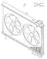
- Fig. 2 is a perspective view showing the cooling unit of Fig. 1.
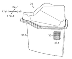
- Fig. 3 is a front view of an air intake resonator.
- Fig. 4 is a plan view of the air intake resonator of Fig. 3.
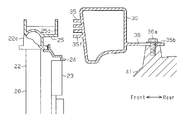
- Fig. 5 is a schematic cross-sectional view showing the positional relationship of the cooling unit and the air intake resonator in the engine compartment.
- Fig. 6 is a schematic view showing the cooling unit and the other components in a frontal collision.
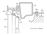
- Fig. 7 is a schematic cross-sectional view showing the positional relation between the cooling unit and the air intake resonator in a frontal collision.
- the vehicle is a hybrid vehicle including an engine and a motor as driving sources.
- the terms "front”, “rear”, “right”, and “left” refer to the front, rear, right, and left of the vehicle.
- a cooling unit 20, an air intake resonator 30, and an engine 41 are arranged in the right section of an engine compartment 10a of a vehicle 10.
- the cooling unit 20, the air intake resonator 30, and the engine 41 are laid out parallel to the front-rear axis of the vehicle 10.
- the air intake resonator 30 is connected to the upstream side of an air cleaner 34 through a hose 33.
- the resonance effect of the air intake resonator 30 reduces the noise of the intake air produced in an intake passage.
- the air cleaner 34 is arranged on the left side of the air intake resonator 30 and the rear side of the cooling unit 20.
- An inverter 43 that drives the motor 42 is arranged in the left section of the engine compartment 10a.
- the inverter 43 and the motor 42 are arranged behind the cooling unit 20.
- the cooling unit 20 is separated from the inverter 43 by a relatively large clearance.
- the cooling unit 20 and the air intake resonator 30 are fastened in the engine compartment 10a adjacent to each other and separated from each other by a relatively small clearance.
- the cooling unit 20 includes a radiator 22 and fans 23. Cooling fins 22a, which contact the passing air, and tubes 22b, which circulate coolant for the engine 41, are arranged in the radiator 22.
- the cooling unit 20 further includes an upper tank 22c and a lower tank 22d. The tanks 22c and 22d are in communication with the tubes 22b and store the coolant.
- the fans 23 and a fan shroud 24 are attached to the rear side of the radiator 22. The fans 23 draw air from the front toward the rear and through the radiator 22 to promote heat exchange.
- the cooling unit 20 further includes a projection 25 arranged on the right end section of the upper tank 22c.
- the projection 25 projects rearward from the upper tank 22c.
- the projection 25 includes a flat surface 25b at the distal end.
- the projecting length, which is the distance between the upper tank 22c and the flat surface 25b, of the projection 25 is set such that, of all the parts of the cooling unit 20, the flat surface 25b of the projection 25 is the closest to the air intake resonator 30 when the cooling unit 20 is accommodated in the engine compartment 10a of the vehicle 10.
- the air intake resonator 30 includes a front surface 30f, which faces the cooling unit 20, and a pressure receiving portion 35, which projects frontward from the front surface 30f.
- the pressure receiving portion 35 includes a plurality of ribs 35f projecting forward, or toward the cooling unit 20. In the pressure receiving portion 35, vertically extending ribs 35f traverse horizontally extending ribs 35f in a grid pattern.
- the position and the projecting length of the pressure receiving portion 35 are set such that the pressure receiving portion 35 faces the projection 25 of the cooling unit 20 and, of all the parts of the air intake resonator 30, the distal end of the pressure receiving portion 35 is the closest to the cooling unit 20 when the air intake resonator 30 is accommodated in the engine compartment 10a of the vehicle 10.
- the projecting length of the pressure receiving portion 35 is the distance between the front surface 30f and the distal ends of the ribs 35f.
- the air intake resonator 30 includes connection portions 35b and 35c extending rearward.
- the connection portion 35b which is located in the left section of the air intake resonator 30, includes an elongated fastening hole 36 extending parallel to the front-rear axis of the vehicle 10.
- the connection portion 35c which is located in the right section of the air intake resonator 30, includes a circular fastening hole 37.
- a fastener 36a is inserted through the fastening hole 36 and a fastener 37a is inserted through the fastening hole 37 to fasten the air intake resonator 30 to the engine 41.
- the air intake resonator 30 is fastened to the engine 41 with the fastener 36a received in the rear side of the fastening hole 36. Accordingly, the fastening hole 36 and the fastener 36a, which function as a fastening portion, fasten the air intake resonator 30 to the engine 41 such that the left section of the air intake resonator 30 is movable in the rearward direction.
- the fastening holes 36 and 37 and the fasteners 36a and 37a fasten the air intake resonator 30 to the engine 41 so that the air intake resonator 30 is arranged behind the cooling unit 20 in the engine compartment 10a.
- the cooling unit 20 functions as a first component including the projection 25, and the air intake resonator 30 functions as a second component including the pressure receiving portion 35.
- FIG. 6 shows the positional relationship between the cooling unit 20 and other components when a frontal collision occurs at the right front side of the vehicle 10.
- the cooling unit 20 pivots about its left end, and the right section of the cooling unit 20 moves rearward. This brings the flat surface 25b of the projection 25 of the cooling unit 20 into abutment with the pressure receiving portion 35 of the air intake resonator 30.
- the projection 25 is the first to abut the air intake resonator 30. This leaves a gap between the portion of the cooling unit 20 other than the projection 25 and the portion of the air intake resonator 30 other than the pressure receiving portion 35.
- parts of the cooling unit 20 other than the projection 25, such as hoses and cords coupled to the cooling unit 20, may abut the air intake resonator 30 before the flat surface 25b of the projection 25 abuts the air intake resonator 30.
- the hoses or cords which are relatively flexible, abut the air intake resonator 30, this would not inflict damage that impairs the function of the cooling unit 20. Therefore, in this embodiment, the abutment between the hoses or cords and the air intake resonator 30 in a collision is not taken into consideration, and the projection 25 is considered to be the first to abut the air intake resonator 30.
- hoses and cords are arranged in the engine compartment 10a. In a collision, such hoses or cords may abut the cooling unit 20. However, even if such hoses or cords abut the cooling unit 20, this would not inflict damage that impairs the function of the cooling unit 20.
- the flat surface 25b of the projection 25 of the cooling unit 20 presses the pressure receiving portion 35 of the air intake resonator 30.
- the air intake resonator 30 moves rearward. This is because the pressing on the pressure receiving portion 35 by the projection 25 moves the fastener 36a in the fastening hole 36 from a rear position to a front position. When moved toward the rear, the air intake resonator 30 pivots about the fastening portion including the fastening hole 37 and the fastener 37a (Fig. 4). The cooling unit 20 moves rearward together with the air intake resonator 30.
- the pressure receiving portion 35 of the air intake resonator 30 receives the projection 25 of the cooling unit 20.
- the air intake resonator 30 can be reinforced by reinforcing the pressure receiving portion 35 or the portion on which the pressure receiving portion 35 is arranged to withstand the impact applied when the cooling unit 20 abuts the pressure receiving portion 35.
- the air intake resonator 30 can be effectively reinforced since the portion that abuts the projection 25 may be specified.
- the pressure receiving portion 35 of the air intake resonator 30 includes the grid-shaped ribs 35f. This allows the pressure receiving portion 35 to withstand impact. In addition, the ribs 35f of the pressure receiving portion 35 reinforce the air intake resonator 30.
- the flat surface 25b of the projection 25 of the cooling unit 20 abuts the pressure receiving portion 35 of the air intake resonator 30.
- the flat surface 25b allows the projection 25 to have a larger contact area than when the projection 25 has a sharp distal end. This limits concentration of the load and effectively limits damage in a collision.
- the cooling unit 20 cannot circulate coolant if a tube 22b of the radiator 22 is damaged and leaks the coolant. In addition, if the fan 23 deforms and stops functioning normally, heat exchange is hindered.
- the upper tank 22c which is located in the upper portion of the cooling unit 20 and which stores coolant, has a higher impact resistance than the tubes 22b and fans 23, which provide the cooling function. Further, even if the upper tank 22c deforms, the cooling performance of the radiator 22 would not be affected.
- the projection 25, which is arranged on the upper tank 22c abuts the air intake resonator 30. This limits adverse effects on the cooling performance even if an impact is applied to the cooling unit 20.
- the air intake resonator 30 moves rearward when the projection 25 of the cooling unit 20 abuts the air intake resonator 30. This reduces impact to the cooling unit 20 compared to when the air intake resonator 30 is fastened to be immovable. In a collision, this effectively limits damage that impairs the function of the cooling unit 20.
- the vehicle 10 is a hybrid vehicle using the motor 42 as a driving source in addition to the engine 41.
- the vehicle 10 has more components accommodated in the engine compartment 10a compared to a vehicle using only the engine 41 as the driving source. This reduces the clearance between the components.
- the structure of the present embodiment limits damage in a collision that impairs the function of the cooling unit 20.
- the air intake resonator 30 does not have to be fastened to the engine 41.
- the air intake resonator 30 may be fastened by the fastening holes 36 and 37 and the fasteners 36a and 37a to a portion other than the engine 41 such as a crossmember forming the vehicle body of the vehicle 10.
- the fastening hole 37 of the air intake resonator 30 may be elongated like the fastening hole 36. In this case, when the air intake resonator 30 moves in a collision, the fastener 36a and the fastener 37a both move in the fastening hole 36 and the fastening hole 37, respectively.
- the fastening portion that movably fastens the air intake resonator 30 is not limited to the fastening holes 36 and 37 and the fasteners 36a and 37a, which are received in the fastening holes 36 and 37.
- a sliding device may be used as a fastening portion.
- the sliding device includes a groove extending parallel to the front-rear axis and a locking member received in the groove to be movable along the groove.
- the fastening holes 36 and 37 of the air intake resonator 30 may both be circular so that the air intake resonator 30 is fastened to the engine 41 to be immovable. Even though advantage (6) is not achieved, this modification still has advantages (1) to (5) and (7).
- the projection 25 may be arranged on a portion of the cooling unit 20 other than the upper tank 22c. However, to limit decreases in the cooling performance of the cooling unit 20 caused by an impact applied when the projection 25 abuts the air intake resonator 30, the projection 25 is preferably arranged on a portion that does not provide the cooling function such as the fan shroud 24.
- the flat surface 25b of the projection 25 may be formed in any method as long as the contact area in the distal end of the projection 25 is enlarged.
- the flat surface 25b may be formed by attaching a plate on the distal end of the projection 25.
- the flat surface 25b of the projection 25 may be omitted. However, in order to limit concentration of load on the pressure receiving portion 35 of the air intake resonator 30, it is preferable that the contact area be enlarged by forming the distal end of the projection 25 as a gradually curved surface, for example.
- the ribs 35f do not have to form a grid pattern.
- the pressure receiving portion 35 may include ribs extending in parallel.
- the ribs do not have to be straight.
- the pressure receiving portion 35 may include parallel undulating ribs.
- the pressure receiving portion 35 is not limited to the ribs 35f extending along the front surface 30f of the air intake resonator 30.
- the pressure receiving portion 35 may include a plurality of rod-shaped projections.
- the projecting length of the projection 25 is not limited to the length that allows the projection 25 to be the closest to the air intake resonator 30 among all the parts of the cooling unit 20. That is, the projection 25 may have any length as long as the projection 25 is the first to abut the air intake resonator 30 in a collision in the projection direction of the projection 25, even if a portion of the cooling unit 20 other than the projection 25 is closer to the air intake resonator 30 than the projection 25 when the cooling unit 20 is accommodated in the engine compartment 10a.
- the projecting length of the pressure receiving portion 35 is not limited to the length that allows the pressure receiving portion 35 to be the closest to the cooling unit 20 among all the parts of the air intake resonator 30. That is, the pressure receiving portion 35 may have any length as long as the pressure receiving portion 35 is the first to abut the projection 25 of the cooling unit 20 in a collision in the projection direction of the projection 25, even if a portion of the air intake resonator 30 other than the pressure receiving portion 35 is closer to the cooling unit 20 than the pressure receiving portion 35 when the air intake resonator 30 is accommodated in the engine compartment 10a.
- the air intake resonator 30 may include a projection, and the cooling unit 20 may include a pressure receiving portion.
- the projection of the air intake resonator 30 may include a flat surface like the projection 25 of the present embodiment or may be shaped differently.
- the pressure receiving portion of the cooling unit 20 may be formed in a grid pattern like the pressure receiving portion 35 of the present embodiment or be shaped differently.
- a projection may be arranged in the central and left sections of the cooling unit 20.
- the cooling unit 20 may include a projection and a pressure receiving portion
- the air intake resonator 30 may include a projection, which abuts the pressure receiving portion of the cooling unit 20, and a pressure receiving portion, which abuts the projection of the cooling unit 20.
- the number of the pressure receiving portions 35 may be less than the number of the projections 25.
- the pressure receiving portion 35 may be omitted. That is, the present embodiment may have any structure as long as at least one of the cooling unit 20 and the air intake resonator 30 includes a projection 25. Even when the pressure receiving portion 35 is omitted, advantages (1) and (5) to (7) are still achieved. However, in such a structure, it is preferable that the portion of the cooling unit 20 or the air intake resonator 30 that comes into abutment with the projection 25 be sufficiently reinforced.
- the types and the positions of the components arranged in the engine compartment 10a other than the cooling unit 20 are not limited to the structure shown in Fig. 1.
- a component other than the air intake resonator 30 may be arranged adjacent to the cooling unit 20.
- the projection 25 is provided in at least one of the cooling unit 20 and the component adjacent to the cooling unit 20 to limit damage in a collision that impairs the function of the cooling unit 20.
- the projection 25 and the pressure receiving portion 35 are provided in the right section of the cooling unit 20 and a component arranged in the right section of the engine compartment 10a. If the cooling unit 20 is adjacent to another component and the clearance between the cooling unit 20 and the adjacent component is relatively small, the cooling unit 20 may abut the adjacent component in a collision of the vehicle 10. In this case, the projection 25 and the pressure receiving portion 35 may be provided in the cooling unit 20 and the adjacent component. For example, in the example shown in Fig.
- the projection 25 and the pressure receiving portion 35 may be provided in the cooling unit 20 and the inverter 43. Further, depending of the structure of the cooling unit 20, a projection and a pressure receiving portion may be provided in the cooling unit 20 and a component adjacent to the cooling unit 20 in the vertical direction or a component adjacent to the cooling unit 20 in the lateral direction.
- the engine compartment 10a is located in the front portion of the vehicle 10.
- the present invention is not limited to such a structure.
- the structures of the embodiments and the modified examples may be applied to a vehicle having an engine compartment in the rear portion of the vehicle.
- the vehicle 10 may include only the engine 41 as the driving source.
Landscapes
- Engineering & Computer Science (AREA)
- Chemical & Material Sciences (AREA)
- Combustion & Propulsion (AREA)
- Transportation (AREA)
- Mechanical Engineering (AREA)
- Cooling, Air Intake And Gas Exhaust, And Fuel Tank Arrangements In Propulsion Units (AREA)
- Hybrid Electric Vehicles (AREA)
- Arrangement Or Mounting Of Propulsion Units For Vehicles (AREA)
Abstract
A vehicle includes an engine accommodated in an engine compartment, a cooling unit fastened in the engine compartment, wherein the cooling unit circulates coolant for the engine, and an adjacent member fastened in the engine compartment adjacent to the cooling unit. The cooling unit is one of a first component and a second component, and the adjacent member is the other one of the first component and the second component. At least the first component includes a projection extending in a projection direction toward the second component. The projection is configured such that, of all parts of the first component, the projection is first to abut the second component in a collision in the projection direction.
Description
The present invention relates to a vehicle including an engine accommodated in an engine compartment.
PTL 1 describes a heat shield that covers the lower portion of an air cleaner accommodated in an engine compartment. The heat shield protects the air cleaner from the heat of the radiator. The radiator is arranged in front of the air cleaner. The heat shield includes an elongated fastening hole extending parallel to the front-rear axis of the vehicle. The fastening hole receives a fastener that fastens the heat shield to a crossmember. Thus, when a frontal collision deforms the front portion of the vehicle, the fastener moves in the elongated fastening hole. This moves the heat shield toward the rear.
In the vehicle of PTL 1, the heat shield is fastened to the crossmember to be movable in the rearward direction. Thus, when the front portion of the vehicle is deformed in a collision, the heat shield and components fixed to the heat shield move rearward in the engine compartment. The rearward movement of the components in the engine compartment allows the front portion of the vehicle to be deformed without interference and absorbs the impact of the collision in a preferred manner.
The engine compartment accommodates a cooling unit that circulates engine coolant. The cooling unit includes a radiator and a fan. The radiator includes a tube having cooling fins. The fan sends air to the radiator to enhance heat exchange. In a collision of the vehicle, the following problems may occur if the cooling unit hits another component.
For example, when the tube of the radiator is damaged, coolant may leak from the tube. This may stop the circulation of the coolant. Further, when the fan is deformed, the fan may stop functioning properly and adversely affect heat exchange. Such a situation would lower the engine cooling performance and hinder the driving of engine. In such a case, the driver may not be able to drive the vehicle to a repair shop, for example.
It is an object of the present invention to provide a vehicle that limits damage in a collision that would impair the function of a cooling unit.
To achieve the above object, one aspect of the present invention is a vehicle including an engine accommodated in an engine compartment, a cooling unit fastened in the engine compartment, wherein the cooling unit circulates coolant for the engine, and an adjacent member fastened in the engine compartment adjacent to the cooling unit. The cooling unit is one of a first component and a second component, and the adjacent member is the other one of the first component and the second component. At least the first component includes a projection extending in a projection direction toward the second component. The projection is configured such that, of all parts of the first component, the projection is first to abut the second component in a collision in the projection direction.
Referring to Figs. 1 to 7, one embodiment of a vehicle including an engine accommodated in an engine compartment will now be described. The vehicle is a hybrid vehicle including an engine and a motor as driving sources. In the following description, the terms "front", "rear", "right", and "left" refer to the front, rear, right, and left of the vehicle.
As shown in Fig. 1, a cooling unit 20, an air intake resonator 30, and an engine 41 are arranged in the right section of an engine compartment 10a of a vehicle 10. The cooling unit 20, the air intake resonator 30, and the engine 41 are laid out parallel to the front-rear axis of the vehicle 10. The air intake resonator 30 is connected to the upstream side of an air cleaner 34 through a hose 33. The resonance effect of the air intake resonator 30 reduces the noise of the intake air produced in an intake passage. The air cleaner 34 is arranged on the left side of the air intake resonator 30 and the rear side of the cooling unit 20. An inverter 43 that drives the motor 42 is arranged in the left section of the engine compartment 10a. The inverter 43 and the motor 42 are arranged behind the cooling unit 20.
As shown in Fig. 1, in the vehicle 10, the cooling unit 20 is separated from the inverter 43 by a relatively large clearance. In contrast, the cooling unit 20 and the air intake resonator 30 are fastened in the engine compartment 10a adjacent to each other and separated from each other by a relatively small clearance.
As shown in Fig. 2, the cooling unit 20 includes a radiator 22 and fans 23. Cooling fins 22a, which contact the passing air, and tubes 22b, which circulate coolant for the engine 41, are arranged in the radiator 22. The cooling unit 20 further includes an upper tank 22c and a lower tank 22d. The tanks 22c and 22d are in communication with the tubes 22b and store the coolant. The fans 23 and a fan shroud 24 are attached to the rear side of the radiator 22. The fans 23 draw air from the front toward the rear and through the radiator 22 to promote heat exchange.
The cooling unit 20 further includes a projection 25 arranged on the right end section of the upper tank 22c. The projection 25 projects rearward from the upper tank 22c. The projection 25 includes a flat surface 25b at the distal end. The projecting length, which is the distance between the upper tank 22c and the flat surface 25b, of the projection 25 is set such that, of all the parts of the cooling unit 20, the flat surface 25b of the projection 25 is the closest to the air intake resonator 30 when the cooling unit 20 is accommodated in the engine compartment 10a of the vehicle 10.
As shown in Fig. 3, the air intake resonator 30 includes a front surface 30f, which faces the cooling unit 20, and a pressure receiving portion 35, which projects frontward from the front surface 30f. The pressure receiving portion 35 includes a plurality of ribs 35f projecting forward, or toward the cooling unit 20. In the pressure receiving portion 35, vertically extending ribs 35f traverse horizontally extending ribs 35f in a grid pattern. The position and the projecting length of the pressure receiving portion 35 are set such that the pressure receiving portion 35 faces the projection 25 of the cooling unit 20 and, of all the parts of the air intake resonator 30, the distal end of the pressure receiving portion 35 is the closest to the cooling unit 20 when the air intake resonator 30 is accommodated in the engine compartment 10a of the vehicle 10. The projecting length of the pressure receiving portion 35 is the distance between the front surface 30f and the distal ends of the ribs 35f.
As shown in Fig. 4, the air intake resonator 30 includes connection portions 35b and 35c extending rearward. The connection portion 35b, which is located in the left section of the air intake resonator 30, includes an elongated fastening hole 36 extending parallel to the front-rear axis of the vehicle 10. The connection portion 35c, which is located in the right section of the air intake resonator 30, includes a circular fastening hole 37. A fastener 36a is inserted through the fastening hole 36 and a fastener 37a is inserted through the fastening hole 37 to fasten the air intake resonator 30 to the engine 41. The air intake resonator 30 is fastened to the engine 41 with the fastener 36a received in the rear side of the fastening hole 36. Accordingly, the fastening hole 36 and the fastener 36a, which function as a fastening portion, fasten the air intake resonator 30 to the engine 41 such that the left section of the air intake resonator 30 is movable in the rearward direction.
The fastening holes 36 and 37 and the fasteners 36a and 37a fasten the air intake resonator 30 to the engine 41 so that the air intake resonator 30 is arranged behind the cooling unit 20 in the engine compartment 10a.
As shown in Fig. 5, when the cooling unit 20 and the air intake resonator 30 are fastened in the engine compartment 10a of the vehicle 10, the projection 25 of the cooling unit 20 projects toward the air intake resonator 30. In addition, the flat surface 25b at the distal end of the projection 25 faces the pressure receiving portion 35 of the air intake resonator 30. Further, the pressure receiving portion 35 projects toward the projection 25. In the present embodiment, the cooling unit 20 functions as a first component including the projection 25, and the air intake resonator 30 functions as a second component including the pressure receiving portion 35.
Referring to Figs. 6 and 7, the operation of the vehicle 10 will now be described. Fig. 6 shows the positional relationship between the cooling unit 20 and other components when a frontal collision occurs at the right front side of the vehicle 10.
As shown in Fig. 6, when a collision in the projection direction of the projection 25, or a frontal collision occurs at the right front side of the vehicle 10, the cooling unit 20 pivots about its left end, and the right section of the cooling unit 20 moves rearward. This brings the flat surface 25b of the projection 25 of the cooling unit 20 into abutment with the pressure receiving portion 35 of the air intake resonator 30. Thus, of all the parts of the cooling unit 20, the projection 25 is the first to abut the air intake resonator 30. This leaves a gap between the portion of the cooling unit 20 other than the projection 25 and the portion of the air intake resonator 30 other than the pressure receiving portion 35.
When the cooling unit 20 moves rearward, parts of the cooling unit 20 other than the projection 25, such as hoses and cords coupled to the cooling unit 20, may abut the air intake resonator 30 before the flat surface 25b of the projection 25 abuts the air intake resonator 30. However, even if the hoses or cords, which are relatively flexible, abut the air intake resonator 30, this would not inflict damage that impairs the function of the cooling unit 20. Therefore, in this embodiment, the abutment between the hoses or cords and the air intake resonator 30 in a collision is not taken into consideration, and the projection 25 is considered to be the first to abut the air intake resonator 30.
In addition to the hoses and cords coupled to the cooling unit 20, other various hoses and cords are arranged in the engine compartment 10a. In a collision, such hoses or cords may abut the cooling unit 20. However, even if such hoses or cords abut the cooling unit 20, this would not inflict damage that impairs the function of the cooling unit 20.
As the cooling unit 20 moves further rearward, the flat surface 25b of the projection 25 of the cooling unit 20 presses the pressure receiving portion 35 of the air intake resonator 30.
As shown in Fig. 7, when the projection 25 presses the pressure receiving portion 35 of the air intake resonator 30, the air intake resonator 30 moves rearward. This is because the pressing on the pressure receiving portion 35 by the projection 25 moves the fastener 36a in the fastening hole 36 from a rear position to a front position. When moved toward the rear, the air intake resonator 30 pivots about the fastening portion including the fastening hole 37 and the fastener 37a (Fig. 4). The cooling unit 20 moves rearward together with the air intake resonator 30.
When a frontal collision occurs at the left front side of the vehicle 10, the cooling unit 20 pivots about its right end, and the left section of the cooling unit 20 moves rearward. However, in the vehicle 10, there is a relatively large clearance between the cooling unit 20 and the inverter 43 in a direction parallel to the front-rear axis of the vehicle 10. Thus, even if the left section of the cooling unit 20 moves rearward, the cooling unit 20 is less likely to hit the inverter 43. Accordingly, in the vehicle 10 of the present embodiment, impact of the cooling unit 20 against the inverter 43 may be avoided without arranging the projection 25 on the left section of the cooling unit 20 and the pressure receiving portion 35 on the inverter 43.
The advantages of the present embodiment will now be described.
(1) In a collision, the parts of the cooling unit 20 other than the projection 25 remain spaced apart by a gap from the air intake resonator 30. Thus, the parts of the cooling unit 20 that provide the cooling function such as the radiator 22 and the fans 23 are less likely to strike the air intake resonator 30. In a collision, this limits damage that impairs the function of the cooling unit 20.
(2) In a collision, the pressure receiving portion 35 of the air intake resonator 30 receives the projection 25 of the cooling unit 20. Thus, the air intake resonator 30 can be reinforced by reinforcing the pressure receiving portion 35 or the portion on which the pressure receiving portion 35 is arranged to withstand the impact applied when the cooling unit 20 abuts the pressure receiving portion 35. In other words, the air intake resonator 30 can be effectively reinforced since the portion that abuts the projection 25 may be specified.
(3) The pressure receiving portion 35 of the air intake resonator 30 includes the grid-shaped ribs 35f. This allows the pressure receiving portion 35 to withstand impact. In addition, the ribs 35f of the pressure receiving portion 35 reinforce the air intake resonator 30.
(4) In a collision, the flat surface 25b of the projection 25 of the cooling unit 20 abuts the pressure receiving portion 35 of the air intake resonator 30. The flat surface 25b allows the projection 25 to have a larger contact area than when the projection 25 has a sharp distal end. This limits concentration of the load and effectively limits damage in a collision.
(5) The cooling unit 20 cannot circulate coolant if a tube 22b of the radiator 22 is damaged and leaks the coolant. In addition, if the fan 23 deforms and stops functioning normally, heat exchange is hindered. The upper tank 22c, which is located in the upper portion of the cooling unit 20 and which stores coolant, has a higher impact resistance than the tubes 22b and fans 23, which provide the cooling function. Further, even if the upper tank 22c deforms, the cooling performance of the radiator 22 would not be affected. In the present embodiment, the projection 25, which is arranged on the upper tank 22c, abuts the air intake resonator 30. This limits adverse effects on the cooling performance even if an impact is applied to the cooling unit 20.
In a frontal collision, the air intake resonator 30 moves rearward when the projection 25 of the cooling unit 20 abuts the air intake resonator 30. This reduces impact to the cooling unit 20 compared to when the air intake resonator 30 is fastened to be immovable. In a collision, this effectively limits damage that impairs the function of the cooling unit 20.
(7) The vehicle 10 is a hybrid vehicle using the motor 42 as a driving source in addition to the engine 41. Thus, the vehicle 10 has more components accommodated in the engine compartment 10a compared to a vehicle using only the engine 41 as the driving source. This reduces the clearance between the components. However, even in such a hybrid vehicle 10, the structure of the present embodiment limits damage in a collision that impairs the function of the cooling unit 20.
It should be apparent to those skilled in the art that the present invention may be embodied in many other specific forms without departing from the spirit or scope of the invention. Particularly, it should be understood that the present invention may be embodied in the following forms.
The air intake resonator 30 does not have to be fastened to the engine 41. The air intake resonator 30 may be fastened by the fastening holes 36 and 37 and the fasteners 36a and 37a to a portion other than the engine 41 such as a crossmember forming the vehicle body of the vehicle 10.
The fastening hole 37 of the air intake resonator 30 may be elongated like the fastening hole 36. In this case, when the air intake resonator 30 moves in a collision, the fastener 36a and the fastener 37a both move in the fastening hole 36 and the fastening hole 37, respectively.
The fastening portion that movably fastens the air intake resonator 30 is not limited to the fastening holes 36 and 37 and the fasteners 36a and 37a, which are received in the fastening holes 36 and 37. For example, a sliding device may be used as a fastening portion. The sliding device includes a groove extending parallel to the front-rear axis and a locking member received in the groove to be movable along the groove.
The fastening holes 36 and 37 of the air intake resonator 30 may both be circular so that the air intake resonator 30 is fastened to the engine 41 to be immovable. Even though advantage (6) is not achieved, this modification still has advantages (1) to (5) and (7).
The projection 25 may be arranged on a portion of the cooling unit 20 other than the upper tank 22c. However, to limit decreases in the cooling performance of the cooling unit 20 caused by an impact applied when the projection 25 abuts the air intake resonator 30, the projection 25 is preferably arranged on a portion that does not provide the cooling function such as the fan shroud 24.
The flat surface 25b of the projection 25 may be formed in any method as long as the contact area in the distal end of the projection 25 is enlarged. For example, the flat surface 25b may be formed by attaching a plate on the distal end of the projection 25.
The flat surface 25b of the projection 25 may be omitted. However, in order to limit concentration of load on the pressure receiving portion 35 of the air intake resonator 30, it is preferable that the contact area be enlarged by forming the distal end of the projection 25 as a gradually curved surface, for example.
The ribs 35f do not have to form a grid pattern. For example, the pressure receiving portion 35 may include ribs extending in parallel. In addition, the ribs do not have to be straight. For example, the pressure receiving portion 35 may include parallel undulating ribs.
The pressure receiving portion 35 is not limited to the ribs 35f extending along the front surface 30f of the air intake resonator 30. For example, the pressure receiving portion 35 may include a plurality of rod-shaped projections.
The projecting length of the projection 25 is not limited to the length that allows the projection 25 to be the closest to the air intake resonator 30 among all the parts of the cooling unit 20. That is, the projection 25 may have any length as long as the projection 25 is the first to abut the air intake resonator 30 in a collision in the projection direction of the projection 25, even if a portion of the cooling unit 20 other than the projection 25 is closer to the air intake resonator 30 than the projection 25 when the cooling unit 20 is accommodated in the engine compartment 10a.
The projecting length of the pressure receiving portion 35 is not limited to the length that allows the pressure receiving portion 35 to be the closest to the cooling unit 20 among all the parts of the air intake resonator 30. That is, the pressure receiving portion 35 may have any length as long as the pressure receiving portion 35 is the first to abut the projection 25 of the cooling unit 20 in a collision in the projection direction of the projection 25, even if a portion of the air intake resonator 30 other than the pressure receiving portion 35 is closer to the cooling unit 20 than the pressure receiving portion 35 when the air intake resonator 30 is accommodated in the engine compartment 10a.
The air intake resonator 30 may include a projection, and the cooling unit 20 may include a pressure receiving portion. In this case, the projection of the air intake resonator 30 may include a flat surface like the projection 25 of the present embodiment or may be shaped differently. Further, the pressure receiving portion of the cooling unit 20 may be formed in a grid pattern like the pressure receiving portion 35 of the present embodiment or be shaped differently.
There is no limitation to the numbers of the projections 25 and the pressure receiving portions 35 arranged in the cooling unit 20 and the air intake resonator 30. For example, in addition to the projection 25 in the right section of the cooling unit 20 of the present embodiment, a projection may be arranged in the central and left sections of the cooling unit 20.
The cooling unit 20 may include a projection and a pressure receiving portion, and the air intake resonator 30 may include a projection, which abuts the pressure receiving portion of the cooling unit 20, and a pressure receiving portion, which abuts the projection of the cooling unit 20.
The number of the pressure receiving portions 35 may be less than the number of the projections 25. In addition, the pressure receiving portion 35 may be omitted. That is, the present embodiment may have any structure as long as at least one of the cooling unit 20 and the air intake resonator 30 includes a projection 25. Even when the pressure receiving portion 35 is omitted, advantages (1) and (5) to (7) are still achieved. However, in such a structure, it is preferable that the portion of the cooling unit 20 or the air intake resonator 30 that comes into abutment with the projection 25 be sufficiently reinforced.
The types and the positions of the components arranged in the engine compartment 10a other than the cooling unit 20 are not limited to the structure shown in Fig. 1. A component other than the air intake resonator 30 may be arranged adjacent to the cooling unit 20. In this case, the projection 25 is provided in at least one of the cooling unit 20 and the component adjacent to the cooling unit 20 to limit damage in a collision that impairs the function of the cooling unit 20.
In the embodiments and the modified examples described above, to deal with a frontal collision to the right front side of the vehicle 10, the projection 25 and the pressure receiving portion 35 are provided in the right section of the cooling unit 20 and a component arranged in the right section of the engine compartment 10a. If the cooling unit 20 is adjacent to another component and the clearance between the cooling unit 20 and the adjacent component is relatively small, the cooling unit 20 may abut the adjacent component in a collision of the vehicle 10. In this case, the projection 25 and the pressure receiving portion 35 may be provided in the cooling unit 20 and the adjacent component. For example, in the example shown in Fig. 1, if the clearance between the cooling unit 20 and the inverter 43 is relatively small in the left section of the engine compartment 10a, the projection 25 and the pressure receiving portion 35 may be provided in the cooling unit 20 and the inverter 43. Further, depending of the structure of the cooling unit 20, a projection and a pressure receiving portion may be provided in the cooling unit 20 and a component adjacent to the cooling unit 20 in the vertical direction or a component adjacent to the cooling unit 20 in the lateral direction.
In the embodiments and the modified examples described above, the engine compartment 10a is located in the front portion of the vehicle 10. However, the present invention is not limited to such a structure. For example, the structures of the embodiments and the modified examples may be applied to a vehicle having an engine compartment in the rear portion of the vehicle.
The vehicle 10 may include only the engine 41 as the driving source.
Claims (8)
- A vehicle (10) comprising:
an engine (41) accommodated in an engine compartment (10a);
a cooling unit (20) fastened in the engine compartment (10a), wherein the cooling unit (20) circulates coolant for the engine (41); and
an adjacent member (30) fastened in the engine compartment (10a) adjacent to the cooling unit (20), wherein
the cooling unit (20) is one of a first component and a second component, and the adjacent member (30) is the other one of the first component and the second component,
at least the first component includes a projection (25) extending in a projection direction toward the second component, and
the projection (25) is configured such that, of all parts of the first component, the projection (25) is first to abut the second component in a collision in the projection direction. - The vehicle (10) according to claim 1, wherein
the second component includes a pressure receiving portion (35) projecting toward the projection (25), and
the pressure receiving portion (35) is configured such that the projection (25) abuts the pressure receiving portion (35) in a collision in the projection direction. - The vehicle (10) according to claim 2, wherein the pressure receiving portion (35) includes a grid-shaped rib (35f).
- The vehicle (10) according to claim 2 or 3, wherein the projection (25) includes a distal end having a flat surface (25b) that faces the pressure receiving portion (35).
- The vehicle (10) according to any one of claims 1 to 4, wherein
the cooling unit (20) includes an upper portion including a tank (22c) for storing coolant, and
the projection (25) is arranged on the tank (22c). - The vehicle (10) according to any one of claims 1 to 5, further comprising a fastening portion (36, 36a, 37, 37a) fastening the adjacent member (30) in a manner allowing the adjacent member (30) to move in a rearward direction of the vehicle (10),
wherein the adjacent member (30) is located rearward from the cooling unit (20) in a direction parallel to a front-rear axis of the vehicle (10). - The vehicle (10) according to claim 6, wherein
the adjacent member (30) includes the fastening portion (36, 36a, 37, 37a), and
the fastening portion (36, 36a, 37, 37a) includes an elongated fastening hole (36) extending parallel to the front-rear axis and a fastener (36a) inserted through the fastening hole (36). - The vehicle (10) according to any one of claims 1 to 7, further comprising a motor (42) accommodated in the engine compartment (10a),
wherein the engine (41) and the motor (42) function as driving sources.
Applications Claiming Priority (2)
| Application Number | Priority Date | Filing Date | Title |
|---|---|---|---|
| JP2013161544A JP2015030384A (en) | 2013-08-02 | 2013-08-02 | vehicle |
| JP2013-161544 | 2013-08-02 |
Publications (1)
| Publication Number | Publication Date |
|---|---|
| WO2015015703A1 true WO2015015703A1 (en) | 2015-02-05 |
Family
ID=51176435
Family Applications (1)
| Application Number | Title | Priority Date | Filing Date |
|---|---|---|---|
| PCT/JP2014/003394 Ceased WO2015015703A1 (en) | 2013-08-02 | 2014-06-25 | Vehicle |
Country Status (2)
| Country | Link |
|---|---|
| JP (1) | JP2015030384A (en) |
| WO (1) | WO2015015703A1 (en) |
Cited By (1)
| Publication number | Priority date | Publication date | Assignee | Title |
|---|---|---|---|---|
| US10908589B2 (en) | 2016-03-17 | 2021-02-02 | Siemens Aktiengesellschaft | Method for determining the orientation of a part to be additively manufactured, and computer-readable medium |
Citations (6)
| Publication number | Priority date | Publication date | Assignee | Title |
|---|---|---|---|---|
| JP2007001526A (en) | 2005-06-27 | 2007-01-11 | Mazda Motor Corp | Auxiliary machinery support structure for vehicles |
| EP2112012A1 (en) * | 2008-04-23 | 2009-10-28 | Toyoda Iron Works Co., Ltd. | Vehicular radiator supporting apparatus |
| WO2010004422A2 (en) * | 2008-07-08 | 2010-01-14 | Toyota Jidosha Kabushiki Kaisha | Cooling conduit arrangement for hybrib vehicle with two radiators |
| FR2952330A1 (en) * | 2009-11-06 | 2011-05-13 | Peugeot Citroen Automobiles Sa | Front structure for automobile, has striking member arranged opposite to functional member so that striking member strikes functional member to cause rupture or deformation of connection unit, under effect of impact subjected by vehicle |
| US20110226542A1 (en) * | 2010-03-16 | 2011-09-22 | GM Global Technology Operations LLC | Cooling module for motor vehicles and motor vehicle |
| EP2508380A2 (en) * | 2011-04-04 | 2012-10-10 | Calsonic Kansei Corporation | Heat-exchanger protection structure |
Family Cites Families (4)
| Publication number | Priority date | Publication date | Assignee | Title |
|---|---|---|---|---|
| JP2008037177A (en) * | 2006-08-02 | 2008-02-21 | Toyota Motor Corp | Support structure for air conditioning / cooling unit for hybrid vehicle |
| JP4816364B2 (en) * | 2006-09-25 | 2011-11-16 | トヨタ自動車株式会社 | Vehicle front structure |
| JP2011178348A (en) * | 2010-03-03 | 2011-09-15 | Honda Motor Co Ltd | Power source system for vehicle |
| JP2012056493A (en) * | 2010-09-10 | 2012-03-22 | Toyota Motor Corp | Mobile object mounted with fuel cell |
-
2013
- 2013-08-02 JP JP2013161544A patent/JP2015030384A/en active Pending
-
2014
- 2014-06-25 WO PCT/JP2014/003394 patent/WO2015015703A1/en not_active Ceased
Patent Citations (6)
| Publication number | Priority date | Publication date | Assignee | Title |
|---|---|---|---|---|
| JP2007001526A (en) | 2005-06-27 | 2007-01-11 | Mazda Motor Corp | Auxiliary machinery support structure for vehicles |
| EP2112012A1 (en) * | 2008-04-23 | 2009-10-28 | Toyoda Iron Works Co., Ltd. | Vehicular radiator supporting apparatus |
| WO2010004422A2 (en) * | 2008-07-08 | 2010-01-14 | Toyota Jidosha Kabushiki Kaisha | Cooling conduit arrangement for hybrib vehicle with two radiators |
| FR2952330A1 (en) * | 2009-11-06 | 2011-05-13 | Peugeot Citroen Automobiles Sa | Front structure for automobile, has striking member arranged opposite to functional member so that striking member strikes functional member to cause rupture or deformation of connection unit, under effect of impact subjected by vehicle |
| US20110226542A1 (en) * | 2010-03-16 | 2011-09-22 | GM Global Technology Operations LLC | Cooling module for motor vehicles and motor vehicle |
| EP2508380A2 (en) * | 2011-04-04 | 2012-10-10 | Calsonic Kansei Corporation | Heat-exchanger protection structure |
Cited By (1)
| Publication number | Priority date | Publication date | Assignee | Title |
|---|---|---|---|---|
| US10908589B2 (en) | 2016-03-17 | 2021-02-02 | Siemens Aktiengesellschaft | Method for determining the orientation of a part to be additively manufactured, and computer-readable medium |
Also Published As
| Publication number | Publication date |
|---|---|
| JP2015030384A (en) | 2015-02-16 |
Similar Documents
| Publication | Publication Date | Title |
|---|---|---|
| KR101189244B1 (en) | Air duct | |
| JP5227063B2 (en) | Intake duct for vehicle | |
| US10059291B2 (en) | Vehicle lower structure | |
| US7150335B2 (en) | Front end structure of vehicle | |
| US20140251241A1 (en) | Vehicle front portion structure | |
| US8869925B2 (en) | Heat-exchanger protection structure | |
| CN106132750A (en) | Refrigerating module | |
| JP2012236504A (en) | Air guide for vehicle | |
| US20130244562A1 (en) | Airflow directing member for a vehicle engine compartment | |
| JP5520787B2 (en) | Front spoiler structure for automobiles | |
| JP2001278115A (en) | Vehicle front end structure | |
| CN110173338B (en) | Cooling device for vehicle | |
| US20180361847A1 (en) | Suspended grille active shutter | |
| JP2007326431A (en) | Seal duct | |
| JP2012246933A (en) | Intake duct for vehicle | |
| KR20130007831A (en) | Airflap apparatus for an automobile | |
| WO2015015703A1 (en) | Vehicle | |
| JP2007245858A (en) | Vehicular air guide | |
| CN102695632B (en) | Bumper module | |
| JP2008155739A (en) | Air guide for vehicle | |
| JP2015200235A (en) | Intake device | |
| US20110120792A1 (en) | Air guide device for front face structure of vehicle | |
| JP5573342B2 (en) | Front body structure of the vehicle | |
| KR101720982B1 (en) | Airflap apparatus for an automobile | |
| KR101923645B1 (en) | Air-duct for Motor Vehicle |
Legal Events
| Date | Code | Title | Description |
|---|---|---|---|
| 121 | Ep: the epo has been informed by wipo that ep was designated in this application |
Ref document number: 14738646 Country of ref document: EP Kind code of ref document: A1 |
|
| NENP | Non-entry into the national phase |
Ref country code: DE |
|
| 122 | Ep: pct application non-entry in european phase |
Ref document number: 14738646 Country of ref document: EP Kind code of ref document: A1 |