WO2015012034A1 - Work vehicle - Google Patents
Work vehicle Download PDFInfo
- Publication number
- WO2015012034A1 WO2015012034A1 PCT/JP2014/066390 JP2014066390W WO2015012034A1 WO 2015012034 A1 WO2015012034 A1 WO 2015012034A1 JP 2014066390 W JP2014066390 W JP 2014066390W WO 2015012034 A1 WO2015012034 A1 WO 2015012034A1
- Authority
- WO
- WIPO (PCT)
- Prior art keywords
- tractor
- lamp
- bonnet
- cabin
- work
- Prior art date
Links
Images


Classifications
-
- B—PERFORMING OPERATIONS; TRANSPORTING
- B60—VEHICLES IN GENERAL
- B60R—VEHICLES, VEHICLE FITTINGS, OR VEHICLE PARTS, NOT OTHERWISE PROVIDED FOR
- B60R1/00—Optical viewing arrangements; Real-time viewing arrangements for drivers or passengers using optical image capturing systems, e.g. cameras or video systems specially adapted for use in or on vehicles
- B60R1/12—Mirror assemblies combined with other articles, e.g. clocks
- B60R1/1207—Mirror assemblies combined with other articles, e.g. clocks with lamps; with turn indicators
-
- B—PERFORMING OPERATIONS; TRANSPORTING
- B60—VEHICLES IN GENERAL
- B60Q—ARRANGEMENT OF SIGNALLING OR LIGHTING DEVICES, THE MOUNTING OR SUPPORTING THEREOF OR CIRCUITS THEREFOR, FOR VEHICLES IN GENERAL
- B60Q1/00—Arrangement of optical signalling or lighting devices, the mounting or supporting thereof or circuits therefor
- B60Q1/0029—Spatial arrangement
- B60Q1/0035—Spatial arrangement relative to the vehicle
-
- B—PERFORMING OPERATIONS; TRANSPORTING
- B60—VEHICLES IN GENERAL
- B60Q—ARRANGEMENT OF SIGNALLING OR LIGHTING DEVICES, THE MOUNTING OR SUPPORTING THEREOF OR CIRCUITS THEREFOR, FOR VEHICLES IN GENERAL
- B60Q1/00—Arrangement of optical signalling or lighting devices, the mounting or supporting thereof or circuits therefor
- B60Q1/0029—Spatial arrangement
- B60Q1/0041—Spatial arrangement of several lamps in relation to each other
-
- B—PERFORMING OPERATIONS; TRANSPORTING
- B60—VEHICLES IN GENERAL
- B60Q—ARRANGEMENT OF SIGNALLING OR LIGHTING DEVICES, THE MOUNTING OR SUPPORTING THEREOF OR CIRCUITS THEREFOR, FOR VEHICLES IN GENERAL
- B60Q1/00—Arrangement of optical signalling or lighting devices, the mounting or supporting thereof or circuits therefor
- B60Q1/02—Arrangement of optical signalling or lighting devices, the mounting or supporting thereof or circuits therefor the devices being primarily intended to illuminate the way ahead or to illuminate other areas of way or environments
- B60Q1/04—Arrangement of optical signalling or lighting devices, the mounting or supporting thereof or circuits therefor the devices being primarily intended to illuminate the way ahead or to illuminate other areas of way or environments the devices being headlights
- B60Q1/18—Arrangement of optical signalling or lighting devices, the mounting or supporting thereof or circuits therefor the devices being primarily intended to illuminate the way ahead or to illuminate other areas of way or environments the devices being headlights being additional front lights
-
- B—PERFORMING OPERATIONS; TRANSPORTING
- B60—VEHICLES IN GENERAL
- B60Q—ARRANGEMENT OF SIGNALLING OR LIGHTING DEVICES, THE MOUNTING OR SUPPORTING THEREOF OR CIRCUITS THEREFOR, FOR VEHICLES IN GENERAL
- B60Q1/00—Arrangement of optical signalling or lighting devices, the mounting or supporting thereof or circuits therefor
- B60Q1/02—Arrangement of optical signalling or lighting devices, the mounting or supporting thereof or circuits therefor the devices being primarily intended to illuminate the way ahead or to illuminate other areas of way or environments
- B60Q1/24—Arrangement of optical signalling or lighting devices, the mounting or supporting thereof or circuits therefor the devices being primarily intended to illuminate the way ahead or to illuminate other areas of way or environments for lighting other areas than only the way ahead
-
- B—PERFORMING OPERATIONS; TRANSPORTING
- B60—VEHICLES IN GENERAL
- B60Q—ARRANGEMENT OF SIGNALLING OR LIGHTING DEVICES, THE MOUNTING OR SUPPORTING THEREOF OR CIRCUITS THEREFOR, FOR VEHICLES IN GENERAL
- B60Q1/00—Arrangement of optical signalling or lighting devices, the mounting or supporting thereof or circuits therefor
- B60Q1/26—Arrangement of optical signalling or lighting devices, the mounting or supporting thereof or circuits therefor the devices being primarily intended to indicate the vehicle, or parts thereof, or to give signals, to other traffic
- B60Q1/2607—Arrangement of optical signalling or lighting devices, the mounting or supporting thereof or circuits therefor the devices being primarily intended to indicate the vehicle, or parts thereof, or to give signals, to other traffic comprising at least two indicating lamps
-
- B—PERFORMING OPERATIONS; TRANSPORTING
- B60—VEHICLES IN GENERAL
- B60Q—ARRANGEMENT OF SIGNALLING OR LIGHTING DEVICES, THE MOUNTING OR SUPPORTING THEREOF OR CIRCUITS THEREFOR, FOR VEHICLES IN GENERAL
- B60Q1/00—Arrangement of optical signalling or lighting devices, the mounting or supporting thereof or circuits therefor
- B60Q1/26—Arrangement of optical signalling or lighting devices, the mounting or supporting thereof or circuits therefor the devices being primarily intended to indicate the vehicle, or parts thereof, or to give signals, to other traffic
- B60Q1/2661—Arrangement of optical signalling or lighting devices, the mounting or supporting thereof or circuits therefor the devices being primarily intended to indicate the vehicle, or parts thereof, or to give signals, to other traffic mounted on parts having other functions
- B60Q1/2665—Arrangement of optical signalling or lighting devices, the mounting or supporting thereof or circuits therefor the devices being primarily intended to indicate the vehicle, or parts thereof, or to give signals, to other traffic mounted on parts having other functions on rear-view mirrors
-
- B—PERFORMING OPERATIONS; TRANSPORTING
- B60—VEHICLES IN GENERAL
- B60Q—ARRANGEMENT OF SIGNALLING OR LIGHTING DEVICES, THE MOUNTING OR SUPPORTING THEREOF OR CIRCUITS THEREFOR, FOR VEHICLES IN GENERAL
- B60Q1/00—Arrangement of optical signalling or lighting devices, the mounting or supporting thereof or circuits therefor
- B60Q1/26—Arrangement of optical signalling or lighting devices, the mounting or supporting thereof or circuits therefor the devices being primarily intended to indicate the vehicle, or parts thereof, or to give signals, to other traffic
- B60Q1/32—Arrangement of optical signalling or lighting devices, the mounting or supporting thereof or circuits therefor the devices being primarily intended to indicate the vehicle, or parts thereof, or to give signals, to other traffic for indicating vehicle sides, e.g. clearance lights
-
- B—PERFORMING OPERATIONS; TRANSPORTING
- B60—VEHICLES IN GENERAL
- B60R—VEHICLES, VEHICLE FITTINGS, OR VEHICLE PARTS, NOT OTHERWISE PROVIDED FOR
- B60R1/00—Optical viewing arrangements; Real-time viewing arrangements for drivers or passengers using optical image capturing systems, e.g. cameras or video systems specially adapted for use in or on vehicles
- B60R1/02—Rear-view mirror arrangements
- B60R1/06—Rear-view mirror arrangements mounted on vehicle exterior
-
- B—PERFORMING OPERATIONS; TRANSPORTING
- B60—VEHICLES IN GENERAL
- B60Q—ARRANGEMENT OF SIGNALLING OR LIGHTING DEVICES, THE MOUNTING OR SUPPORTING THEREOF OR CIRCUITS THEREFOR, FOR VEHICLES IN GENERAL
- B60Q2800/00—Features related to particular types of vehicles not otherwise provided for
- B60Q2800/20—Utility vehicles, e.g. for agriculture, construction work
Definitions
- the present invention relates to a work vehicle.
- a side mirror is attached to a cabin frame via a mounting plate. Further, the vicinity of the mounting plate of the cabin frame is reinforced by a strut handle member so that the side mirror does not vibrate due to vibration during engine or running.
- the mounting plate itself is not reinforced in the work vehicle, there is a possibility that the vibration of the side mirror is amplified by the mounting plate when the side mirror is disposed at a position away from the cabin.
- This invention is made in view of the subject which concerns, and it aims at provision of the working vehicle which can arrange
- the support arm in a work vehicle in which a side mirror is provided at the other end of a support arm that is fixed to a cabin that covers one end of the driving operation unit, the support arm is bent in the middle and sandwiched between the bent portions.
- a beam is formed integrally with the support arm, and the cross-sectional area of the cross section perpendicular to the axial direction of the support arm is configured to decrease from one end to the other end.
- a front work lamp that irradiates the front of the work vehicle is provided in the vicinity of one end side of the support arm, and a protective cover that protects the light source body of the front irradiation lamp connects the support arm and the cabin. It is provided.
- the front side surface of the side mirror is formed on a spherical surface that expands toward the front of the work vehicle, and a vehicle width lamp is provided along the shape of the front side surface.
- the weight of the other side end is reduced while the rigidity of one side end (cabin side end) of the support arm and the bending portion are ensured.
- a side mirror can be arrange
- the rigidity of the one end portion of the support arm is further improved by the front work lamp cover provided at the one end portion (cabin side end portion) of the support arm.
- a side mirror can be arrange
- the side mirror provided with the vehicle width lamp is arranged at a position away from the cabin. Therefore, the vehicle width and the vehicle height of the work vehicle can be known at the same time while ensuring the rear view.
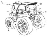
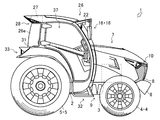
- the partial expanded side view which shows the structure of the bonnet of the tractor which concerns on one Embodiment of this invention.
- the partial enlarged top view which shows the structure of the bonnet of the tractor which concerns on one Embodiment of this invention.
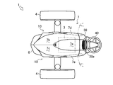
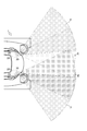
- (A) The figure which shows the range showing the blind spot from the driving operation part of the tractor which concerns on the conventional embodiment
- (b) The figure which shows the range showing the blind spot from the driving operation part of the tractor which concerns on one Embodiment of this invention.
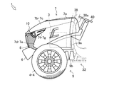
- the partial expansion perspective view which shows the structure of the weight of a tractor and front grill which concerns on one Embodiment of this invention.
- the partial expanded front view which shows the structure of the headlamp which concerns on one Embodiment of this invention.
- the partial expanded side view which shows the structure of the headlamp which concerns on one Embodiment of this invention.
- the partial enlarged top view which shows the irradiation direction of LED flash of the headlamp which concerns on one Embodiment of this invention.
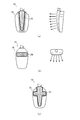
- the partial enlarged front view which shows the structure of the side mirror which concerns on one Embodiment of this invention, a front work lamp, and a vehicle width lamp.
- the partial enlarged front view which shows the structure of the side mirror which concerns on another embodiment of this invention, a front work lamp, and a vehicle width lamp.
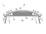
- the partial expanded rear view which shows the structure of the cabin of the tractor which concerns on one Embodiment of this invention.
- the figure which shows the range which the back work light of the tractor which concerns on one Embodiment of this invention irradiates.
- the partial expanded side view which shows the structure of the fender and step of the tractor which concern on one Embodiment of this invention.
- the partial enlarged top view which shows the structure of the step of the tractor which concerns on one Embodiment of this invention.
- the partial expansion rear perspective view which shows the structure of the combination lamp of the tractor which concerns on one Embodiment of this invention.
- tractor 1 which is the first embodiment of the work vehicle according to the present invention.
- front-rear and left-right directions are defined with the forward direction of the tractor 1 being the front.
- the work vehicle according to the present invention is not limited to the tractor 1 according to the present embodiment, but can be widely applied to other vehicles such as other agricultural vehicles, construction vehicles, and industrial vehicles.
- the tractor 1 is equipped with various work machines (such as a rotary) to perform various operations.
- an engine 3 a bonnet 7, a transmission case (not shown), a front axle, a rear axle, a cabin 26, a driving operation unit 37, and the like are disposed on a body frame 2 whose longitudinal direction is a longitudinal direction.
- a counterweight 6 or the like is attached to the front end of the machine body frame 2 via a front hitch (not shown).
- An engine 3 (see FIGS. 3 and 4) is mounted at a substantially central portion of the body frame 2.
- a transmission case (not shown) that houses a part of the power transmission mechanism of the tractor 1 is connected to the rear end of the body frame 2.
- the front part of the body frame 2 is supported by a pair of left and right front wheels 4 via a front axle (not shown).
- the rear part of the transmission case is supported by a pair of left and right rear wheels 5 via a rear axle (not shown).
- the body frame 2 and the transmission case are integrally formed, and are supported by the front wheels 4 and the rear wheels 5.
- the tractor 1 has an engine room with a bonnet 7 and the like disposed so as to cover the engine 3.
- the tractor 1 is provided with a front grill 8 and a headlamp 10 for illuminating the front in front of the bonnet 7.
- the tractor 1 is provided with a driving operation unit 37 for operating the tractor 1 by the operator boarding behind the hood 7 and above the transmission case.
- the driving operation unit 37 is covered with the cabin 26.
- the tractor 1 is provided with a work implement mounting device (not shown) behind the transmission case.
- the tractor 1 configured as described above is transmitted to the pair of left and right front wheels 4 and rear wheels 5 through the front axle and the rear axle after the power of the engine 3 is shifted by the power transmission mechanism.
- the tractor 1 travels by rotationally driving a pair of left and right front wheels 4 and rear wheels 5.
- the tractor 1 is also applied to a work machine such as a tillage device (not shown) mounted via the work machine mounting device provided behind the transmission case after the power of the engine 3 is shifted by the power transmission mechanism. Communicated.
- the counterweight 6 balances the weight of the work machine attached to the work machine mounting device.
- the counterweight 6 is provided at the front end portion of the tractor 1.
- the counterweight 6 is formed in a substantially V shape in plan view with the center in the left-right direction protruding forward.
- the counterweight 6 is formed in the inclined surface where an upper surface falls toward the center of the left-right direction. That is, the counterweight 6 is formed in a V shape when viewed from the front in the traveling direction.
- the tractor 1 does not contact the front end portion of the bonnet 7 and the counterweight 6 when the bonnet 7 opens and closes so that the rear end of the bonnet 7 is directed forward (see FIG. 3).
- the bonnet 7 constitutes an engine room in which the engine 3 and the like are arranged.
- the bonnet 7 is provided on the body frame 2 so as to cover from the front end portion of the body frame 2 on which the engine 3 is disposed to the cabin 26 with the longitudinal direction as the longitudinal direction.
- the bonnet 7 has an opening at its front end.
- a front grill 8 is provided at the opening of the bonnet 7.
- the bonnet 7 is configured to be able to rotate upward with the front end portion or the rear end portion as a fulcrum to open the engine room (see black arrows in FIG. 3).
- the bonnet 7 includes an upper side surface 7a, an upper left side surface 7b, an upper right side surface 7c, a left side surface 7d, and a right side surface 7e.
- adjacent side surfaces of the upper side surface 7a, the upper left side surface 7b, the upper right side surface 7c, the left side surface 7d, and the right side surface 7e are integrally formed.
- the upper side surface 7a is formed in a substantially triangular shape with its apex facing forward in plan view.
- the upper side surface 7 a constitutes a part of the bonnet 7 having the apex at the substantially center in the front-rear direction of the bonnet 7 from the rear end of the bonnet 7.
- the upper side surface 7 a is formed as an inclined surface that falls from the rear end of the bonnet 7 toward the front end.
- the upper left side surface 7b constitutes a part of the bonnet 7 from the rear end of the bonnet 7 on the left side of the upper side surface 7a to the front end of the bonnet 7.
- the upper right side surface 7 c constitutes a part of the bonnet 7 from the rear end of the bonnet 7 that is the right side of the upper side surface 7 a to the front end of the bonnet 7.
- a part of the bonnet 7 composed of the upper left side surface 7b and the upper right side surface 7c gradually increases in width in the left-right direction from the rear end to the front end of the bonnet 7, and the width in the left-right direction from the middle portion. It is formed to become gradually smaller.
- the bonnet 7 is comprised by the substantially bullet shape in which a left ridgeline and a right ridgeline correspond in the center of a front end in planar view.
- the upper left side surface 7b and the upper right side surface 7c are configured to be adjacent to the upper side surface 7a from the rear end of the bonnet 7 to the apex of the upper side surface 7a.
- the upper left side surface 7 b and the upper right side surface 7 c are configured to be adjacent to each other at the center in the left-right direction of the bonnet 7 from the apex of the upper side surface 7 a to the front end of the bonnet 7.
- the upper left side surface 7b is formed as an inclined surface that goes down to the left.
- the upper right side surface 7c is formed as an inclined surface that descends to the right.
- the upper left side surface 7 b and the upper right side surface 7 c are formed as inclined surfaces that descend from the apex of the upper side surface 7 a toward the front end of the bonnet 7. Accordingly, a part of the bonnet 7 constituted by the upper side surface 7a, the upper left side surface 7b, and the upper right side surface 7c has a height from the ground from the rear end to the front end and from the center in the left-right direction to the left-right direction. Is configured to be low.
- the left side surface 7d constitutes a part of the bonnet 7 so as to be directed to the body frame 2 adjacent to the left end of the upper left side surface 7b.
- the right side surface 7e constitutes a part of the bonnet 7 so as to be directed to the body frame 2 adjacent to the right end of the upper right side surface 7c.
- a cooling air discharge port for cooling the engine 3 is formed in the left side surface 7d and the right side surface 7e.
- a notch toward the rear end of the bonnet 7 is formed at the upper end of the front end portion of the left side surface 7d and the upper end of the front end portion of the right side surface 7e.
- a cut portion 7 f is configured from the lower end of the upper left side surface 7 b and the cutout of the left side surface 7 d.
- a cut portion 7g is formed on the right side of the front end portion of the bonnet 7 from the lower end of the upper right side surface 7c and the cutout of the right side surface 7e.
- the bonnet 7 has an instrument panel 38 connected to the rear end.
- the shape of the upper side surface 7a, the upper left side surface 7b, the upper right side surface 7c, the left side surface 7d, and the rear end of the right side surface 7e of the bonnet 7 is formed substantially the same as the shape of the front end of the instrument panel 38. That is, the instrument panel 38 is continuously connected to the bonnet 7 without a step.
- the instrument panel 38 is formed with an inclined surface 38 a that descends from a connection end with the bonnet 7 toward the driving operation unit 37 in the cabin 26. That is, the instrument panel 38 is configured so as not to be higher than the hood 7 from the ground.
- the field of view of the front of the driver (including the left front and the right front) is shielded by the bonnet 7 and a blind spot is generated. That is, in the tractor 1, the higher the height from the ground of the hood 7 relative to the height from the ground of the pilot, the more blind spots are generated in the field of view ahead of the pilot (hereinafter referred to as the height from the ground of the pilot). The height of each part from the ground relative to the height).
- the tractor 100 having a conventional bonnet shape that is not formed in a cannonball shape in plan view has the same height as the center of the front end of the bonnet as viewed from the operator at the left and right ends in front of the bonnet. It is configured. Therefore, the blind spot B of the tractor 100 includes a blind spot generated by the left and right ends in front of the bonnet.
- the tractor 1 in the present embodiment has a lower height from the ground of the bonnet 7 toward the left and right sides from the front end of the bonnet 7 and the center of the bonnet 7 in the left-right direction. It is comprised so that it may become.
- the left and right ends of the front end of the bonnet 7 are lower than the height of the center of the front end of the bonnet 7.
- the height of the instrument panel 38 from the ground is not higher than that of the hood 7. Therefore, the blind spot A of the tractor 1 does not include the blind spot generated by the left and right ends in front of the bonnet 7 and the blind spot generated by the instrument panel 38. That is, the blind spot A of the tractor 1 is reduced in the blind spot generated at the left front and the right front compared to the blind spot B of the tractor 100.
- the tractor 1 reduces the proportion of the bonnet 7 in the field of view of the front, left front, and right front of the driver. Moreover, the tractor 1 reduces the ratio of the bonnet 7 in the field of view of the left front and the right front of the operator. Further, in the tractor 1, the proportion of the instrument panel 38 in the field of view ahead of the driver is reduced. Thereby, the tractor 1 can reduce the blind spot produced ahead.
- the front grill 8 covers a supply port for taking cooling air from the engine 3 and the like into the engine room from the outside.
- the front grill 8 is provided in an opening that is a supply port formed at the front end of the bonnet 7.
- the front grill 8 is made of resin or metal.
- the front grill 8 is formed with a plurality of long holes 8a whose longitudinal direction is the left-right direction.
- the tractor 1 can reduce the resistance at the time of external air passing the front grille 8 compared with the case where a plurality of round holes are formed.
- the side cover 9 covers the space between the left and right bonnets 7 and the body frame 2.
- the side cover 9 includes an upper side cover 9a and a lower side cover 9b.
- the upper side cover 9a is made of a net-like member, and is provided below the left side surface 7d and the right side surface 7e of the bonnet 7 so as to cover the space from the front wheel 4 to the cabin 26.
- the lower side cover 9b is provided below the upper side cover 9a of each of the left side surface 7d and the right side surface 7e so as to cover the body frame 2.
- the upper side cover 9 a and the lower side cover 9 b are fixed to the body frame 2.
- the tractor 1 With this configuration, in the tractor 1, various devices related to the engine 3 and the like that are not covered by the hood 7 and the body frame 2 are covered from the outside by the side cover 9. As a result, the tractor 1 releases the hot air in the engine room from the upper side cover 9a to the outside, and prevents the earth and sand, etc., rolled up by the front wheels 4 during traveling by the side cover 9 from entering the body frame 2 and the engine room. can do. In addition, the tractor 1 can escape the hot air in the engine room from the upper side cover 9a to the outside, and can take in fresh fresh air in the engine room.
- the headlamp 10 illuminates the front of the tractor 1.
- the headlamp 10 is provided at the left end and the right end of the front end portion of the bonnet 7.
- the left and right headlamps 10 are provided in cut portions 7 f and 7 g formed on the right side and the left side of the front end portion of the bonnet 7.
- the headlamp 10 includes a housing 11, a reflector 12, a bulb 13, an LED flasher 14, and a headlamp cover 15.
- the headlamp is configured to light together with a vehicle width lamp 19 described later. That is, the tractor 1 is configured such that the headlamp 10 is lit after the vehicle width lamp 19 is lit.
- the housing 11 is a main component of the headlamp 10, to which the reflector 12, the bulb 13, the LED flasher 14, and the headlamp cover 15 are attached.
- casing 11 is formed in the substantially triangular pyramid shape which can be attached to the notch part 7f * 7g of the bonnet 7, respectively.
- casing 11 is formed so that the end surface by the side of the large diameter which is a substantially triangular pyramid-shaped bottom face may open. That is, the housing 11 is formed with a recess 11 a for assembling the reflector 12, the valve 13, and the like with the end surface on the large diameter side as the front end surface of the housing 11.
- the left and right casings 11 are respectively assembled to the notches 7f and 7g with the recess 11a formed on the front end face facing the front of the tractor 1.
- the left and right housings 11 have the first vertex 11d of the three vertices of the front end surface, which is a substantially triangular pyramid-shaped bottom surface, facing the center of the bonnet 7 in the left-right direction, and the second vertex 11e facing the bonnet 7. It is arranged toward the outside in the left-right direction.
- the left and right casings 11 are assembled to the bonnet 7 so that the distance between the left side surface of the left casing 11 and the right side surface of the right casing 11 is substantially the same as the maximum width in the left-right direction of the bonnet 7. ing.
- the vertex (first vertex 11 d) on the front end surface of the bonnet 7 in the left-right direction is closer to the front end of the bonnet 7 than the vertex on the outer side in the left-right direction (second vertex 11 e).
- the front end surfaces of the left and right casings 11 are formed so as to protrude forward from the outside in the left-right direction of the bonnet 7 toward the center side in the left-right direction of the bonnet 7 in plan view. That is, the left casing 11 is formed in a shape that allows the front end face to be viewed from the left side of the tractor 1, and the right casing 11 has the front end face viewed from the right side of the tractor 1. It is formed in a shape that can be made.
- a reflector 11b that collects and reflects external light is provided on the left side surface of the left housing 11 and the right side surface of the right housing 11.
- the reflector 12 reflects the light from the bulb 13 as a reflecting means.
- the reflector 12 is formed in a substantially dome shape that reflects the light of the bulb 13 disposed substantially at the center thereof in a certain direction.
- the reflectors 12 are respectively assembled in the recesses 11 a of the left and right casings 11 so that light is reflected toward the front of the tractor 1.
- the reflector 12 is configured in a substantially dome shape on the outer side in the left-right direction of the bonnet 7 in the housing 11, and the center side in the left-right direction of the bonnet 7 in the housing 11 from a portion configured in a substantially dome shape. It is composed up to the end.
- the bulb 13 generates light as a main light source body.
- the bulb 13 is composed of an arbitrary type of light source such as a halogen lamp or an HID lamp.
- the valve 13 is assembled at a predetermined position substantially at the center of the reflector 12 configured in a substantially dome shape. Thereby, most of the light generated from the bulb 13 is irradiated toward the front of the tractor 1 by the reflector 12. On the other hand, a part of the light generated from the bulb 13 is irradiated in the left-right direction of the tractor 1 by the reflector 12 provided until reaching the end of the bonnet 7 on the center side in the left-right direction.
- the valve 13 is assembled at a predetermined position substantially at the center of the reflector 12 configured in a substantially dome shape. Thereby, most of the light generated from the bulb 13 is irradiated toward the front of the tractor 1 by the reflector 12. On the other hand, a part of the light generated from the bulb 13 is irradiated in the left-right direction of the tractor 1 by
- the LED flasher 14 generates light as an auxiliary light source body.
- the LED flasher 14 is composed of a plurality of LEDs.
- the LED flashers 14 are provided on the front end surfaces of the left and right casings 11 so that the LEDs are arranged in a line.
- the LED flasher 14 has LEDs arranged from the outside in the left-right direction of the bonnet 7 toward the center in the left-right direction at the front end. Thereby, the LED flasher 14 can be visually recognized not only from the front of the tractor 1 but also from the left side and the right side (see FIG. 15).
- the LED flasher 14 is configured to be turned on when a vehicle width lamp 19 described later is turned on.
- the LED flasher 14 is comprised from several LED, you may be comprised from another light source.
- the headlight cover 15 protects the reflector 12, the bulb 13, and the LED flasher 14 in the housing 11.
- the headlamp cover 15 is made of a material that transmits light from the bulb 13 and the LED flasher 14.
- the headlamp cover 15 is provided on each of the front end surfaces of the left and right casings 11 so as to cover the reflector 12, the bulb 13 and the LED flasher 14 disposed in the recess 11 a of the casing 11 (FIG. 13, The shaded portion in FIG.
- the tractor 1 reflects the light of the bulb 13 by the reflector 12 and the housing while irradiating light in the traveling direction by the bulb 13 which is the main light source body of the left and right headlamps 10.
- 11 is reflected to the front, left and right of the tractor 1 by reflection of external light by the reflector 11b or transmitted light from the slit 11c of the bulb 13 and an LED flasher 14 provided on the front end surface of the housing 11. Irradiate.
- the notches 7 f and 7 g formed in the bonnet 7 the reflection of the light of the bulb 13 by the reflector 12 from the front end surface of the headlamp 19 that is visible from the side of the tractor 1 is not blocked by the bonnet 7. Thereby, the visibility from the front, left side, and right side of the tractor 1 can be improved.
- the side mirror 16 visually recognizes the rear of the tractor 1.
- the left and right side mirrors 16 are respectively provided on both upper ends of the front side surface 26 b of the cabin 26.
- the side mirror 16 includes a support arm 17, a front work lamp 22, a mirror section 18, and a vehicle width lamp 19.
- the left and right support arms 17 support the mirror portion 18 and the vehicle width lamp 19.
- the support arm 17 is composed of a rod-shaped member having a rectangular shape in a cross-sectional view perpendicular to the axial direction.
- the support arm 17 is formed in a substantially L shape having a bent portion 17a in the middle.
- the support arm 17 has a long side portion side end (one side end) fixed to both upper side end portions of the front side surface 26 b of the cabin 26.
- the support arm 17 has a rectangular cross-sectional area Ar in a cross-sectional view perpendicular to the axial direction that decreases from one side end toward the short side end (other end) where the mirror portion 18 is supported. It is formed as follows. That is, the support arm 17 is configured such that the weight per unit length decreases from one side end fixed to the cabin 26 to the other side end. Further, the support arm 17 is integrally formed with a beam 17b that connects one side and the other side so as to straddle the bent portion 17a. Thereby, since the weight of the other side end part is reduced while the rigidity of the one side end part and the rigidity of the bending part 17b are ensured, the vibration of the other side end is suppressed.
- the left support arm 17 is provided so that the long side portion is directed to the front left side from the front side surface 26b.
- the right support arm 17 is provided so that the long side portion is directed to the front right side from the front side surface 26b.
- the left and right support arms 17 are provided so that the short sides are directed downward from the bent portion 17a.
- the support arm 17 has a position in the front-rear direction of the bent portion 17a near the rear end of the bonnet 7 (see FIGS. 3 and 4), and a position in the left-right direction of the bent portion 17a is the width of the rear wheel 5. It is configured so as to be substantially in the center (see FIG. 5), and the height of the bent portion 17a is in the vicinity of the ceiling 26f of the cabin 26 (see FIGS. 3 and 4). That is, the support arm 17 is configured so that the mirror unit 18 is disposed at a position spaced forward from the cabin 26 (driving operation unit 37) on the left and right sides.
- the mirror unit 18 holds a mirror.
- the mirror portion 18 is provided with a mirror 18b inside a box-shaped housing 18a having an opening.
- the mirror unit 18 is configured such that a mirror 18b is provided in the opening of the housing 18a so that the reflection surface of the mirror 18b can be viewed from the outside.
- the mirror part 18 is connected to the short-side end of the support arm 17 so that the reflecting surface of the mirror 18 b faces the rear of the tractor 1. That is, the mirror part 18 is arrange
- the mirror unit 18 is configured so that the reflecting surface of the mirror 18 b can be directed in an arbitrary direction with respect to the support arm 17.
- the vehicle width lamp 19 is for visually checking the vehicle width of the tractor 1.
- the vehicle width lamp 19 is composed of a plurality of LEDs.
- the vehicle width lamp 19 is a casing 18a of the left and right mirror portions 18, and is provided on a surface (back surface) facing the opening. That is, the vehicle width lamp 19 is configured to light toward the front of the tractor 1 on the side opposite to the reflecting surface of the mirror 18 b of the mirror portion 18 directed to the rear of the tractor 1.
- the vehicle width lamp 19 can indicate the approximate vehicle width and vehicle height of the tractor 1 by being provided on the left and right mirror portions 18.
- the vehicle width lamp 19 can also be used as a direction indicator by blinking one of the left and right vehicle width lights 19.
- the tractor 1 has the mirror unit 18 disposed at a position spaced apart from the cabin 26 on the left and right sides in front and above. Thereby, the tractor 1 can be made to know the vehicle width and the vehicle height of the tractor 1 at the same time while ensuring a rear view.
- the vehicle width lamp 19 has a plurality of LEDs arranged on the mirror portion 18 in an arbitrary manner.
- the vehicle width lamp 19 which is the first embodiment of the vehicle width lamp includes a plurality of LEDs arranged in the vertical direction on the back surface of the casing 18a of the mirror portion 18.
- the vehicle width lamp 19 forms the back surface of the housing
- the vehicle width lamp 19 may be provided in the vicinity of the bent portion 17 a of the support arm 17. Specifically, the vehicle width lamp 19 is attached using a surface constituted by a bent portion 17a and a beam 17b of the support arm 17.
- the vehicle width lamp 19 is always lit in a constant direction and position regardless of the direction of the mirror unit 18. Thereby, the tractor 1 can be made to know simultaneously a vehicle width and a vehicle height, ensuring the back view.
- the vehicle width lamp 20 which is 2nd embodiment of a vehicle width lamp is comprised by the back side of the housing
- variety lamp 20 can disperse
- the vehicle width lamp 21 which is 3rd embodiment of a vehicle width lamp, several LED is located in the back surface of the housing
- the tractor 1 sets the irradiation direction of the vehicle width lamp 19 according to the shape of the casing 18a of the mirror 18 and the arrangement of the LEDs of the vehicle width lamp 19. Thereby, the tractor 1 can be made to know simultaneously a vehicle width and a vehicle height, ensuring the back view.
- the front work lamp 22 illuminates the front of the tractor 1.
- the front work lamps 22 are respectively provided at one side end portions (long side portion side end portions) of the left and right support arms 17.
- the front work lamp 22 includes an upper work lamp 23, a lower work lamp 24, and a front work lamp cover 25.
- the front work lamp 22 has an upper work lamp 23 and a lower work lamp 24 arranged in the vertical direction below one end of the support arm 17.
- the front work lamp cover 25 is formed of a material that transmits light from the upper work lamp 23 and the lower work lamp 24.
- the front work lamp cover 25 covers the upper work lamp 23 and the lower work lamp 24, and is configured to connect the lower side surface of the support arm 17 and the front side surface 26b of the cabin 26 (shaded portion in FIG. 16). reference). That is, the front work lamp cover 25 improves the rigidity of the support arm 17 while protecting the upper work lamp 23 and the lower work lamp 24. Thereby, as for the support arm 17, the rigidity of one side edge part improves further, and a vibration is suppressed.
- the front work lamp 22 is configured such that the upper work lamp 23 and the lower work lamp 24 illuminate an arbitrary range, respectively.
- the left and right front work lights 22 illuminate the irradiation range C in which the upper work light 23 is on the left front and right front of the tractor 1, respectively.
- the lamp 24 is configured to illuminate an irradiation range D that is in front of the tractor 1.
- the left and right front work lights 22 illuminate the irradiation range D in which the upper work lamp 23 is in front of the tractor 1, and the left and right lower work lights 24 respectively indicate the irradiation range C in which the left front and right front of the tractor 1 are irradiated. You may comprise so that it may shine.
- the tractor 1 sets the irradiation range of the front work lamp 22 so that the irradiation range does not include the side mirror 16.
- the support arm 17 of the side mirror 16 is reinforced by the front work lamp 22. Thereby, the tractor 1 can improve the visibility of the vehicle width lamp 19 while irradiating a wide range with the front work lamp.
- the cabin 26 covers the operation unit 37.
- the cabin 26 has a front side surface 26b, a left side door 26c, a right side door 26d, a rear side surface 26e, and a ceiling 26f formed in a substantially box shape via a cabin frame 26a.
- the cabin 26 is provided with an air conditioner unit 27 and a rear work lamp 28.
- a frame 26a is configured by fixing a frame body of the left door 26c and a frame body of the right door 26d, which are integrally formed, to the body frame 2. That is, in the cabin 26, the left and right side frames of the front side surface 26b, the left and right side frames of the rear side surface 26e, and the left and right side frames of the ceiling 26f are respectively a left side door 26c frame and a right side door 26d frame. As a single unit. Accordingly, the cabin 26 is configured integrally with the front side surface 26b, the rear side surface 26e, and the ceiling 26f.
- the front side surface 26b of the cabin 26 is configured in front of the driving operation unit 37 via a cabin frame 26a.
- the front side surface 26b is provided with a curved glass (or resin, specifically, polycarbonate, acrylic, or the like) covering the floor surface of the driving operation unit 37 to the ceiling 26f of the cabin 26 as a windshield.
- the curved glass constituting the front side surface 26b is formed to be curved into a gentle arc shape with the left-right direction as the axial direction and a gentle arc shape with the vertical direction as the axial direction (white coating in FIG. 20). See arrow). That is, the front side surface 26b is made of a curved glass formed in a substantially spherical shape that swells in the forward direction.
- the curved glass on the front side surface 26b is formed with a cut portion for disposing the instrument panel 38 in the central portion in the left-right direction.
- the left and right side surfaces of the cabin 26 are provided with a left door 26c and a right door 26d, which can open and close the entire surface, with the cabin frame 26a as a frame.
- the left door 26c and the right door 26d are made of curved glass (or resin, specifically, polycarbonate, acrylic, or the like) whose entire surface is curved in a gentle arc shape with the vertical direction as the axial direction ( (See the white arrow in FIG. 20).
- the rear end of the left door 26c and the right door 26d is connected to the cabin frame 26a via a hinge 26g.
- the left door 26c and the right door 26d are provided with an outer handle 26h at the front end.
- a reinforcing bar 26j is provided on the left door 26c and the right door 26d.
- the reinforcing bar 26j is composed of a plate member.
- the reinforcing bar 26j connects the hinge 26g and the outer handle 26h to the operation unit 37 side with the vertical direction as the plate width direction.
- the reinforcing bar 26j is formed with an inner handle 26k used when opening and closing the left door 26c and the right door 26d.
- the inner handle 26k is branched and formed so as to protrude from the midway portion of the reinforcing bar 26j on the hinge 26g side to the driving operation portion 37 (pilot seat 42) side.
- the inner handle 26k is formed in parallel with the reinforcing bar 26j until it reaches the outer handle 26h (see FIG. 28).
- the rear side surface 26e of the cabin 26 is configured behind the driving operation unit 37 via the cabin frame 26a.
- curved glass or resin, specifically, polycarbonate, acrylic, or the like
- the curved glass constituting the rear side surface 26e is formed so that the left and right ends thereof are curved so as to be continuously connected to the left door 26c and the right door 26d.
- the ceiling 26f of the cabin 26 is configured at the upper end portions of the front side surface 26b, the left side door 26c, the right side door 26d, and the rear side surface 26e via the cabin frame 26a.
- the ceiling 26f is provided with a curved glass 26m (or resin, specifically, polycarbonate, acrylic, or the like) that covers from the front end thereof to a position corresponding to the position above the cockpit 42 of the driving operation unit 37.
- the curved glass 26m constituting the ceiling 26f is formed to be curved so as to be continuously connected to the front side surface 26b.
- the ceiling 26f is configured to be curved from the front end to the rear end as a whole.
- the curvature radius of the curved shape of the ceiling 26f increases from the curvature radius R1 in the vicinity of the front end of the ceiling 26f toward the rear end, and is configured to have the curvature radius R2 in the vicinity of the rear end. That is, the ceiling 26f is configured in a circular arc shape that approximates a clothoid curve represented by the following formula, with a curvature radius R and a curve length L.
- Formula: RL A 2 (A: clothoid parameter)
- the ceiling 26f can be configured such that the height from the ground gradually increases toward the rear end. That is, the thickness of the ceiling 26f increases from the thickness H1 in the vicinity of the front end of the ceiling 26f toward the rear end, and becomes the thickness H2 in the vicinity of the rear end (see FIG. 21). Further, the ceiling 26f is formed with an eaves portion 26n in which only the upper end of the rear end surface protrudes rearward from the rear side surface 26e of the cabin 26.
- the ceiling 26f is provided with an air conditioner unit 27 from the rear end of the curved glass 26m to the rear end of the ceiling 26f.
- the eaves 26n at the rear end of the ceiling 26f is provided with an introduction port 26p through which the air conditioner unit 27 takes in outside air, as shown in FIG.
- a louver is provided in the introduction port 26p.
- the tractor 1 is configured by curved glass or resin except for the rear part of the cabin frame 26a and the ceiling 26f. Further, the tractor 1 has improved visibility and rigidity of the cabin 26 by a monocoque structure in which the integrally formed frame 26a is continuously connected by curved glass.
- the left door 26c and the right door 26d can be easily opened and closed, and the left door 26c and the right door 26d are reinforced by the reinforcing bar 26j.
- the tractor 1 can comprise the front side surface 26b, the left side door 26c, the right side door 26d, the rear side surface 26e, and the ceiling 26f of the cabin 26 with glass.
- the thickness of the ceiling 26f of the cabin 26 increases continuously from the ceiling 26f of the cabin 26 toward the rear end. Accordingly, the air conditioner unit can be provided inside the ceiling 26f without causing a part of the ceiling 26f to protrude or separately forming an inlet for the air conditioner unit 27 to take in outside air.
- the rear work lamp 28 illuminates the rear of the tractor 1.
- the left and right rear work lights 28 are respectively provided at both end portions of the inclined surface at the rear end of the ceiling 26f. Between the left and right rear work lights 28, an inlet 26p of the air conditioner unit 27 is formed.
- the rear work lamp 28 includes an outer work lamp 29 and an inner work lamp 30.
- an outer work lamp 29 and an inner work lamp 30 are arranged side by side on the eaves 26n at the rear end of the ceiling 26f in the left-right direction.
- the rear work lamp 28 is covered with a rear work lamp cover 28a (shaded portion in FIG. 22) formed of a material that transmits light from the outer work lamp 29 and the inner work lamp 30.
- the outer work lamp 29 and the inner work lamp 30 are provided so as to face the rear from the inside of the ceiling 26f through the eaves part 26n so as not to protrude from the eaves part 26n.
- the rear work lamp cover 28a is provided so that the rear work lamp 28 is flush with the eaves 26n.
- the rear work lamp 28 is configured such that the outer work lamp 29 and the inner work lamp 30 each illuminate an arbitrary range.
- the rear work light 28 is configured such that the left and right outer work lights 29 illuminate the rear E of the tractor 1 and the left and right inner work lights 30 illuminate the left and right rear F of the tractor 1 (white in FIG. 22). (See painted arrow).
- the rear work light 28 may be configured such that the left and right outer work lights 29 illuminate the left and right rear F of the tractor 1 and the left and right inner work lights 30 illuminate the rear E of the tractor 1.
- the tractor 1 is provided with the rear work lamp 28 (the outer work lamp 29 and the inner work lamp 30) so as to face the rear from the inside of the ceiling 26f of the cabin 26, and the outer work lamp 29 and the inner work lamp.
- the irradiation range of the lamp 30 is set. As a result, it is possible to irradiate a wide area with the rear work lamp 28 without causing the rear work lamp 28 to protrude from the cabin 26.
- the fender 31 is for preventing the sand soil splashed by the rotation of the rear wheel 5 from scattering.
- the fenders 31 are provided on the left and right sides of the cabin 26 so as to cover the tread surfaces (surfaces in contact with the ground) of the left and right rear wheels 5.
- the fender 31 is provided along the tread surface of the rear wheel 5 from the vicinity of the rear side 26e of the cabin 26 to the vicinity of the fuselage frame 2.
- the fender 31 is configured so that the center side in the left-right direction of the tractor 1 is adjacent to the cockpit 42 in the cabin 26. That is, the left and right fenders 31 are arranged on the tractor 1 with the cockpit 42 interposed therebetween.
- the fender 31 is integrally formed on the outside and inside of the cabin 26.
- Step 32 is connected to the front end (the body frame 2 side) of the fender 31.
- an inclined surface 31a is formed that descends downward.
- a combination lamp 33 is provided on the inclined surface 31 a of the fender 31.
- step 32 is for placing the foot G when the operator gets into the cabin 26.
- Steps 32 are provided in front of the rear wheel 5 and in the vicinity of the left door 26c and the right door 26d of the cabin 26, respectively.
- Step 32 includes a front support portion 32a, a receiving portion 32b, and a rear support portion 32c.
- the front support part 32a supports the front of the receiving part 32b.
- One end of the front support portion 32 a is connected to the cabin frame 26 a near the floor of the operation operation portion 37.
- the other end of the front support portion 32a is formed so that the other end reaches the front side of the front side surface 26b of the cabin 26 from the cabin frame 26a.
- the other end of the front support portion 32a is connected to the receiving portion 32b at a predetermined position lower than the axle height of the rear wheel 5. That is, the front support portion 32a is formed to extend obliquely downward from the cabin frame 26a toward the front.
- the other end of the front support portion 32a is connected to the side surface of the receiving portion 32b on the tractor 1 side. That is, the front support portion 32a is connected to the receiving portion 32b so as to open the front end of the receiving portion 32b.
- the rear support part 32c supports the rear of the receiving part 32b.
- the rear support portion 32 c is connected to the front end of the fender 31.
- the rear support portion 32 c has a width substantially the same as the width in the left-right direction outside the cabin 26 at the front end of the fender 31, and is formed along the tread surface of the rear wheel 5 from the front end of the fender 31.
- the rear support portion 32c is connected to the receiving portion 32b at a predetermined position lower than the axle height of the rear wheel 5. That is, the rear support portion 32 c is formed so as to continuously extend from the front end of the fender 31 toward the rear side of the front end of the fender 31 with the same radius of curvature R3 as the fender 31.
- the receiving portion 32b is used to hang the operator's foot G.
- the front and rear ends of the receiving portion 32b are integrally connected to the front support portion 32a and the rear support portion 32c.
- the receiving portion 32 b is connected to the front support portion 32 a in front of the front side surface 26 b of the cabin 26, and is connected to the fender 31 behind the front end of the fender 31.
- the receiving part 32b is formed in the left-right direction width
- a plurality of triangular holes 32d are formed on the surface of the receiver 32b where the operator puts his foot G.
- the holes 32d are arranged so that each side is not parallel to the left-right direction of the receiving portion 32b. Further, the hole 32d is formed so that the sides of the adjacent holes 32d are parallel to each other. That is, the beam-shaped portion between the punched hole 32d and the punched hole 32d of the receiving portion 32b is formed in an oblique direction with respect to the longitudinal direction of the rider's foot G getting on and off.
- the tractor 1 is formed so that the receiving portion 32b of step 32 is wider than the width of the left and right doors near the cabin floor.
- the range in which the operator's foot G is placed is not limited by the front support portion 32a.
- the rear support portion 32 c of the step 32 is formed continuously with the fender 31, the operator's foot G does not contact the front end of the fender 31. Further, the short direction of the operator's foot G is supported by the crosspiece. Thereby, the step 32 can widen the surface on which the operator's foot G of the receiving portion 32b is put, and the sitting of the foot G can be stabilized and the convenience at the time of getting on and off can be improved.
- the combination lamp 33 is integrally formed by combining a direction indicator 34 and a brake lamp 35.
- the combination lamps 33 are respectively provided so as to irradiate rearward to the rear ends of the fenders 31 on the left and right sides.
- the combination lamp 33 is covered with a combination lamp cover 36.
- the combination lamp 33 is formed in a substantially rectangular parallelepiped shape.
- an outer peripheral surface 34 a in the left-right direction and an outer edge portion 34 b (shaded portion in FIG. 26) on the rear side surface are configured as a direction indicator 34.
- the direction indicator 34 is configured such that the outer peripheral surface 34a and the outer edge portion 34b emit light.
- the direction indicator 34 is configured to light up when the brake is used.
- an inner portion 35a of the outer edge 34b on the rear side surface is configured as a brake lamp 35.
- the brake lamp 35 emits light at an inner portion 35a (shaded portion in FIG. 25), and a reflector 35b is formed around the inner portion 35a.
- the light source of the brake lamp 35 is composed of LEDs.
- the light source of the brake lamp 35 is not limited to the LED.
- the combination lamp 33 has a double structure in which the outer peripheral surface 34a, the outer edge 34b of the rear side surface, and the inner portion 35a can be lit independently.
- the combination lamp 33 is provided substantially horizontally with a front end inserted into a rear recess 31b formed in the inclined surface 31a of the fender 31. That is, the combination lamp 33 is provided so as to be hidden inside the fender 31 from the upper front end to the lower rear end of the fender 31.
- the combination lamp 33 is covered with a combination lamp cover 36 on the upper side surface and a part of the side surface in the left-right direction (the outer peripheral surface 34a of the direction indicator 34).
- the combination lamp cover 36 is attached to the inclined surface 31 a of the fender 31.
- the combination lamp cover 36 is formed so as to extend rearward from the middle part of the inclined surface 31 a of the fender 31 beyond the rear end of the combination lamp 33.
- the rear end portion of the combination lamp cover 36 is formed to be inclined upward from a middle portion of the rear end inclination (inclined surface 31a) of the fender 31 in a side view. That is, the combination lamp 33 is configured so that the outer peripheral surface 34 a of the direction indicator 34 can be viewed from the side of the tractor 1 from between the inclination of the rear end of the combination lamp cover 36 and the inclination of the fender 31.
- the form of the direction indicator 34 and the brake lamp 35 in the combination lamp 33 is not limited to this.
- the combination lamp 33 as shown in FIG. 27A, the combination lamp 33 is divided into upper and lower equal parts, a direction indicator 34 is arranged on one of the upper and lower sides, and a brake lamp 35 is arranged on the other upper and lower side.
- the structure to do may be sufficient.
- one of the upper and lower parts is configured to be larger than the other, a direction indicator 34 is disposed on the upper and lower sides, and a brake lamp is provided on the upper and lower sides.
- positions 35 may be sufficient.
- the combination lamp 33 is divided into left and right equal parts or unequal parts, and a direction indicator 34 is provided on the left side face of the left combination lamp 33 and the right side face of the right combination lamp 33.
- positions may be sufficient.
- the tractor 1 forms a shadow on the combination lamp 33 by the combination lamp cover 36.
- adhesion of earth and sand to the combination lamp 33 is reduced by the combination lamp cover 36.
- the tractor 1 can visually recognize the direction indicator 34 of the combination lamp 33 from both sides in the left-right direction while improving the visibility from the rear of the combination lamp 33.
- the driving operation unit 37 performs various operations for driving the tractor 1.
- the driving operation unit 37 is provided inside the cabin 26.
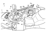
- the driving operation unit 37 includes an instrument panel 38, a steering handle 40, a cockpit 42, an operation panel 43, and the like.
- the instrument panel 38 is provided with various operation devices and instruments.
- the instrument panel 38 is provided at the front left and right center in the cabin 26.
- the instrument panel 38 is connected to the rear end of the bonnet 7.
- the instrument panel 38 is formed in substantially the same shape as the upper side surface 7a, upper left side surface 7b, upper right side surface 7c, left side surface 7d, and rear end of the right side surface 7e of the bonnet 7 (see FIG. 10). That is, the instrument panel 38 is continuously connected to the rear end of the bonnet 7 without a step.
- the instrument panel 38 is formed with an inclined surface 38 a that descends from a connection end with the bonnet 7 toward the driving operation unit 37 in the cabin 26.
- the instrument panel 38 is formed so that the inclined surface 38 a faces the driver who is seated in the cockpit 42.
- the instrument panel 38 is formed with a substantially rectangular air conditioner outlet 38b whose longitudinal direction is the left-right direction in the vicinity of the connection with the bonnet 7, that is, the front end of the instrument panel 38.
- a recess 38c is formed below the air conditioner outlet 38b.
- a touch panel 39 is provided in the recess 38c.
- the touch panel 39 displays and operates various devices such as the traveling speed of the tractor 1, the number of revolutions of the engine 3, a fuel gauge, a water temperature gauge, and operation switches.
- the touch panel 39 is provided so as to have a gentler angle (so that the angle from the horizontal plane becomes smaller) than the angle of the inclined surface 38a of the instrument panel 38. That is, the instrument panel 38 is provided with the touch panel 39 so that the depth of the concave portion 38c increases toward the front. Thereby, the touch panel 39 is configured so that light that is inserted from the front onto the screen by the concave portion 38 a of the instrument panel 38 does not enter.
- the steering handle 40 is for steering the tractor 1.
- the steering handle 40 is provided adjacent to the rear of the instrument panel 38.
- the steering handle 40 is configured to have substantially the same height as the instrument panel 38.
- the steering handle 40 is formed with a convex portion 40 a with the right front and left front facing the center of the steering handle 40.
- the steering handle 40 is supported by the steering column 41 via a plurality of column brackets 40b.
- the steering handle 40 is provided with a switch group 40c for performing various operations on the column bracket 40b.
- the steering handle 40 is connected to column brackets 40b on both sides in the left-right direction and on the side of the cockpit 42 (rear side). That is, the column bracket 40 b is not disposed on the instrument panel 38 side (front side) of the steering handle 40.
- the cockpit 42 is provided behind the steering handle 40 and between the left and right fenders 31.
- An operation panel 43 having an operation lever of the transmission is provided on one of the left and right fenders 31 of the cockpit 42.
- the operation panel 43 is disposed in a side recess 31 c formed in the fender 31. That is, the operation panel 43 is configured integrally with the fender 31.
- the tractor 1 makes it easy for the operator to operate the touch panel 39 provided on the instrument panel 38.
- the tractor 1 is provided with the steering handle 40 in front of the touch panel 39, the operator can easily recognize the display on the touch panel 39. Thereby, the tractor 1 can improve the operability of the touch panel 39 provided on the instrument panel 38.
- the present invention can be used in the technology of work vehicles such as tractors.
Abstract
The purpose of the present invention is to provide a work vehicle with which side mirrors can be disposed in arbitrary positions, and vibration of said side mirrors can be reduced. Accordingly, a tractor (1), i.e. a work vehicle in which mirror parts (18) of side mirrors (16) are provided to other ends of support arms (17) each having one end thereof fixed to a cabin (26) covering a driving/operating part (37), is configured such that: the support arms (17) are bent at midway portions thereof; beams (17b) are integrally formed with the support arms (17) so as to each have a bent part (17a) disposed therebetween; and the cross-sectional area (Ar) of cross sections of the support arms (17), said cross sections each being orthogonal to an axial direction, reduces as each of the support arms (17) extends from the one end thereof to the other end thereof.
Description
本発明は、作業車両に関する。
The present invention relates to a work vehicle.
従来、乗用の作業車両において、運転操作部を覆うキャビンにサイドミラーが設けられたものが知られている。作業車両には、サイドミラーが取り付けプレートを介してキャビンのフレームに取り付けられている。例えば特許文献1のごとくである。
Conventionally, a passenger work vehicle in which a side mirror is provided in a cabin covering a driving operation unit is known. In the work vehicle, side mirrors are attached to the cabin frame via attachment plates. For example, as in Patent Document 1.
特許文献1の作業車両は、キャビンのフレームに取り付けプレートを介してサイドミラーが取り付けられている。さらに、エンジンや走行時の振動によってサイドミラーが振動しないように筋違い取手部材によってキャビンのフレームの取り付けプレート近傍が補強されている。しかし、作業車両は、取り付けプレート自体が補強されていないため、キャビンから離れた位置にサイドミラーを配置すると取り付けプレートによってサイドミラーの振動が増幅される可能性があった。
In the work vehicle of Patent Document 1, a side mirror is attached to a cabin frame via a mounting plate. Further, the vicinity of the mounting plate of the cabin frame is reinforced by a strut handle member so that the side mirror does not vibrate due to vibration during engine or running. However, since the mounting plate itself is not reinforced in the work vehicle, there is a possibility that the vibration of the side mirror is amplified by the mounting plate when the side mirror is disposed at a position away from the cabin.
本発明は係る課題を鑑みてなされたものであり、サイドミラーの振動を低減しつつ、任意の位置にサイドミラーを配置することができる作業車両の提供を目的とする。
This invention is made in view of the subject which concerns, and it aims at provision of the working vehicle which can arrange | position a side mirror in arbitrary positions, reducing the vibration of a side mirror.
本発明の解決しようとする課題は以上の如くであり、次にこの課題を解決するための手段を説明する。
The problems to be solved by the present invention are as described above. Next, means for solving the problems will be described.
即ち、本発明においては、一端が運転操作部を覆うキャビンに固定された支持アームの他端にサイドミラーが設けられている作業車両において、支持アームが途中部で屈曲され、屈曲部を挟むようにして支持アームと一体的にビームが形成され、支持アームの軸方向に垂直な断面の断面積が一端から他端に向かうに連れて小さくなるように構成されているものである。
That is, in the present invention, in a work vehicle in which a side mirror is provided at the other end of a support arm that is fixed to a cabin that covers one end of the driving operation unit, the support arm is bent in the middle and sandwiched between the bent portions. A beam is formed integrally with the support arm, and the cross-sectional area of the cross section perpendicular to the axial direction of the support arm is configured to decrease from one end to the other end.
本発明においては、前記支持アームの一端側近傍に前記作業車両の前方を照射する前方作業灯が設けられ、前方照射灯の光源体を保護する保護カバーが支持アームとキャビンとを連結するように設けられているものである。
In the present invention, a front work lamp that irradiates the front of the work vehicle is provided in the vicinity of one end side of the support arm, and a protective cover that protects the light source body of the front irradiation lamp connects the support arm and the cabin. It is provided.
本発明においては、前記サイドミラーの前側面が前記作業車両の前方に向かって膨らむ球面上に形成され、前側面の形状に沿うようにして車幅灯が設けられているものである。
In the present invention, the front side surface of the side mirror is formed on a spherical surface that expands toward the front of the work vehicle, and a vehicle width lamp is provided along the shape of the front side surface.
本発明の効果として、以下に示すような効果を奏する。
As the effects of the present invention, the following effects are obtained.
本発明によれば、支持アームの一側端部(キャビン側端部)の剛性と屈曲部の剛性とが確保されつつ他側端部(サイドミラー側端部)の重量が軽減される。これにより、サイドミラーの振動を低減しつつ、任意の位置にサイドミラーを配置することができる。
According to the present invention, the weight of the other side end (side mirror side end) is reduced while the rigidity of one side end (cabin side end) of the support arm and the bending portion are ensured. Thereby, a side mirror can be arrange | positioned in arbitrary positions, reducing the vibration of a side mirror.
本発明によれば、支持アームの一側端部(キャビン側端部)に設けられた前方作業灯カバーによって支持アームの一側端部の剛性がさらに向上される。これにより、サイドミラーの振動を低減しつつ、任意の位置にサイドミラーを配置することができる。
According to the present invention, the rigidity of the one end portion of the support arm is further improved by the front work lamp cover provided at the one end portion (cabin side end portion) of the support arm. Thereby, a side mirror can be arrange | positioned in arbitrary positions, reducing the vibration of a side mirror.
本発明によれば、車幅灯が設けられたサイドミラーがキャビンから離れた位置に配置される。これにより、後方の視界を確保しつつ作業車両の車幅と車高とを同時に知らしめることができる。
According to the present invention, the side mirror provided with the vehicle width lamp is arranged at a position away from the cabin. Thereby, the vehicle width and the vehicle height of the work vehicle can be known at the same time while ensuring the rear view.
以下に、本発明に係る作業車両の第一実施形態であるトラクター1について説明する。以下の説明では、トラクター1の前進方向を前方として前後左右方向を規定する。
Hereinafter, the tractor 1 which is the first embodiment of the work vehicle according to the present invention will be described. In the following description, the front-rear and left-right directions are defined with the forward direction of the tractor 1 being the front.
まず、本発明に係るトラクター1の全体構成について図1から図8を用いて説明する。
なお、本発明に係る作業車両は、本実施形態に係るトラクター1に限るものではなく、その他の農業車両や建設車両、産業車両等、広く車両全般に適用することが可能である。 First, the overall configuration of thetractor 1 according to the present invention will be described with reference to FIGS.
The work vehicle according to the present invention is not limited to thetractor 1 according to the present embodiment, but can be widely applied to other vehicles such as other agricultural vehicles, construction vehicles, and industrial vehicles.
なお、本発明に係る作業車両は、本実施形態に係るトラクター1に限るものではなく、その他の農業車両や建設車両、産業車両等、広く車両全般に適用することが可能である。 First, the overall configuration of the
The work vehicle according to the present invention is not limited to the
図1と図2に示すように、トラクター1は、種々の作業機(ロータリ等)を装着し、種々の作業を行うものである。トラクター1は、長手方向を前後方向とする機体フレーム2に、エンジン3、ボンネット7、図示しないトランスミッションケース、フロントアクスル、リアアクスル、キャビン26および運転操作部37等が配置されている。
As shown in FIGS. 1 and 2, the tractor 1 is equipped with various work machines (such as a rotary) to perform various operations. In the tractor 1, an engine 3, a bonnet 7, a transmission case (not shown), a front axle, a rear axle, a cabin 26, a driving operation unit 37, and the like are disposed on a body frame 2 whose longitudinal direction is a longitudinal direction.
機体フレーム2の前端部には、図示しないフロントヒッチを介してカウンターウェイト6等が取り付けられている。機体フレーム2の略中央部には、エンジン3(図3、図4参照)が搭載されている。機体フレーム2の後端部には、トラクター1の動力伝達機構の一部を収納する図示しないトランスミッションケースが連結されている。また、機体フレーム2の前部は、図示しないフロントアクスルを介して左右一対の前輪4に支持されている。トランスミッションケースの後部は、図示しないリアアクスルを介して左右一対の後輪5に支持されている。このように、トラクター1は、機体フレーム2とトランスミッションケースとが一体的に構成され、前輪4と後輪5とによって支持されている。
A counterweight 6 or the like is attached to the front end of the machine body frame 2 via a front hitch (not shown). An engine 3 (see FIGS. 3 and 4) is mounted at a substantially central portion of the body frame 2. A transmission case (not shown) that houses a part of the power transmission mechanism of the tractor 1 is connected to the rear end of the body frame 2. The front part of the body frame 2 is supported by a pair of left and right front wheels 4 via a front axle (not shown). The rear part of the transmission case is supported by a pair of left and right rear wheels 5 via a rear axle (not shown). Thus, in the tractor 1, the body frame 2 and the transmission case are integrally formed, and are supported by the front wheels 4 and the rear wheels 5.
トラクター1は、エンジン3を覆うようにボンネット7等を配置してエンジンルームが構成されている。トラクター1は、ボンネット7の前方には、フロントグリル8と前方を照らす前照灯10とが設けられている。トラクター1は、ボンネット7の後方、かつトランスミッションケースの上方に操縦者が搭乗してトラクター1を操作するための運転操作部37が設けられている。トラクター1は、運転操作部37がキャビン26によって覆われている。また、トラクター1は、トランスミッションケースの後方に図示しない作業機装着装置が設けられている。
The tractor 1 has an engine room with a bonnet 7 and the like disposed so as to cover the engine 3. The tractor 1 is provided with a front grill 8 and a headlamp 10 for illuminating the front in front of the bonnet 7. The tractor 1 is provided with a driving operation unit 37 for operating the tractor 1 by the operator boarding behind the hood 7 and above the transmission case. In the tractor 1, the driving operation unit 37 is covered with the cabin 26. Further, the tractor 1 is provided with a work implement mounting device (not shown) behind the transmission case.
このように構成されているトラクター1は、エンジン3の動力が前記動力伝達機構で変速された後、フロントアクスルとリアアクスルとを経て左右一対の前輪4と後輪5に伝達される。トラクター1は、左右一対の前輪4と後輪5の回転駆動により走行が行われる。また、トラクター1は、エンジン3の動力が前記動力伝達機構で変速された後、トランスミッションケースの後方に設けられた前記作業機装着装置を介して装着された図示しない耕耘装置等の作業機にも伝達される。
The tractor 1 configured as described above is transmitted to the pair of left and right front wheels 4 and rear wheels 5 through the front axle and the rear axle after the power of the engine 3 is shifted by the power transmission mechanism. The tractor 1 travels by rotationally driving a pair of left and right front wheels 4 and rear wheels 5. The tractor 1 is also applied to a work machine such as a tillage device (not shown) mounted via the work machine mounting device provided behind the transmission case after the power of the engine 3 is shifted by the power transmission mechanism. Communicated.
次に、図1を用いて、カウンターウェイト6、ボンネット7、フロントグリル8およびサイドカバー9について説明する。
Next, the counterweight 6, the bonnet 7, the front grille 8, and the side cover 9 will be described with reference to FIG.
図1、図3、図4及び図5に示すように、カウンターウェイト6は、前記作業機装着装置に取り付けられた作業機との重量バランスをとるものである。カウンターウェイト6は、トラクター1の前端部に設けられている。カウンターウェイト6は、左右方向中央が前方に向かって突出した平面視にて略V字状に形成されている。また、カウンターウェイト6は、上側面が左右方向中央に向かって下がる傾斜面に形成されている。すなわち、カウンターウェイト6は、進行方向正面視にてV字状に形成されている。
As shown in FIG. 1, FIG. 3, FIG. 4 and FIG. 5, the counterweight 6 balances the weight of the work machine attached to the work machine mounting device. The counterweight 6 is provided at the front end portion of the tractor 1. The counterweight 6 is formed in a substantially V shape in plan view with the center in the left-right direction protruding forward. Moreover, the counterweight 6 is formed in the inclined surface where an upper surface falls toward the center of the left-right direction. That is, the counterweight 6 is formed in a V shape when viewed from the front in the traveling direction.
このように構成することで、トラクター1は、ボンネット7の後端が前方に向かうようにしてボンネット7が開閉する場合にボンネット7の前端部とカウンターウェイト6とが接触しない(図3参照)。
With this configuration, the tractor 1 does not contact the front end portion of the bonnet 7 and the counterweight 6 when the bonnet 7 opens and closes so that the rear end of the bonnet 7 is directed forward (see FIG. 3).
図9と図10とに示すように、ボンネット7は、エンジン3等が配置されているエンジンルームを構成するものである。ボンネット7は、長手方向を前後方向としてエンジン3が配置されている機体フレーム2の前端部からキャビン26までを覆うようにして機体フレーム2に設けられている。ボンネット7は、その前端に開口部が形成されている。ボンネット7の開口部には、フロントグリル8が設けられている。ボンネット7は、前端部または後端部を支点として上方に回転してエンジンルームを開放可能に構成されている(図3黒塗矢印参照)。
As shown in FIGS. 9 and 10, the bonnet 7 constitutes an engine room in which the engine 3 and the like are arranged. The bonnet 7 is provided on the body frame 2 so as to cover from the front end portion of the body frame 2 on which the engine 3 is disposed to the cabin 26 with the longitudinal direction as the longitudinal direction. The bonnet 7 has an opening at its front end. A front grill 8 is provided at the opening of the bonnet 7. The bonnet 7 is configured to be able to rotate upward with the front end portion or the rear end portion as a fulcrum to open the engine room (see black arrows in FIG. 3).
ボンネット7は、上側面7a、上左側面7b、上右側面7c、左側面7dおよび右側面7eから構成されている。ボンネット7は、上側面7a、上左側面7b、上右側面7c、左側面7dおよび右側面7eのうち隣接する側面同士がそれぞれ一体的に形成されている。
The bonnet 7 includes an upper side surface 7a, an upper left side surface 7b, an upper right side surface 7c, a left side surface 7d, and a right side surface 7e. In the bonnet 7, adjacent side surfaces of the upper side surface 7a, the upper left side surface 7b, the upper right side surface 7c, the left side surface 7d, and the right side surface 7e are integrally formed.
上側面7aは、平面視で前方に頂点を向けた略三角形状に形成されている。上側面7aは、ボンネット7の後端からボンネット7の前後方向略中央を前記頂点とするボンネット7の一部を構成している。上側面7aは、ボンネット7の後端から前端に向かって下がる傾斜面に形成されている。
The upper side surface 7a is formed in a substantially triangular shape with its apex facing forward in plan view. The upper side surface 7 a constitutes a part of the bonnet 7 having the apex at the substantially center in the front-rear direction of the bonnet 7 from the rear end of the bonnet 7. The upper side surface 7 a is formed as an inclined surface that falls from the rear end of the bonnet 7 toward the front end.
上左側面7bは、上側面7aの左側であるボンネット7の後端からボンネット7の前端に到るボンネット7の一部を構成している。上右側面7cは、上側面7aの右側であるボンネット7の後端からボンネット7の前端に到るボンネット7の一部を構成している。上左側面7bと上右側面7cとから構成されているボンネット7の一部は、ボンネット7の後端から前端に向かって左右方向の幅が徐々に大きくなり、途中部から左右方向の幅が徐々に小さくなるように形成されている。そして、ボンネット7は、平面視にて左側稜線と右側稜線とが前端の中央で一致する略砲弾状に構成されている。
The upper left side surface 7b constitutes a part of the bonnet 7 from the rear end of the bonnet 7 on the left side of the upper side surface 7a to the front end of the bonnet 7. The upper right side surface 7 c constitutes a part of the bonnet 7 from the rear end of the bonnet 7 that is the right side of the upper side surface 7 a to the front end of the bonnet 7. A part of the bonnet 7 composed of the upper left side surface 7b and the upper right side surface 7c gradually increases in width in the left-right direction from the rear end to the front end of the bonnet 7, and the width in the left-right direction from the middle portion. It is formed to become gradually smaller. And the bonnet 7 is comprised by the substantially bullet shape in which a left ridgeline and a right ridgeline correspond in the center of a front end in planar view.
上左側面7bと上右側面7cとは、ボンネット7の後端から上側面7aの前記頂点に到るまで上側面7aに隣接するように構成されている。そして、上左側面7bと上右側面7cとは、上側面7aの前記頂点からボンネット7の前端に到るまでボンネット7の左右方向中央にて互いに隣接するように構成されている。上左側面7bは、左方に向かって下がる傾斜面に形成されている。上右側面7cは、右方に向かって下がる傾斜面に形成されている。加えて、上左側面7bと上右側面7cとは、上側面7aの前記頂点からボンネット7の前端に向かって下がる傾斜面に形成されている。これにより、上側面7aと上左側面7bと上右側面7cとから構成されているボンネット7の一部は、後端から前端、および左右方向中央から左右方向のそれぞれに向かって地面からの高さが低くなるように構成されている。
The upper left side surface 7b and the upper right side surface 7c are configured to be adjacent to the upper side surface 7a from the rear end of the bonnet 7 to the apex of the upper side surface 7a. The upper left side surface 7 b and the upper right side surface 7 c are configured to be adjacent to each other at the center in the left-right direction of the bonnet 7 from the apex of the upper side surface 7 a to the front end of the bonnet 7. The upper left side surface 7b is formed as an inclined surface that goes down to the left. The upper right side surface 7c is formed as an inclined surface that descends to the right. In addition, the upper left side surface 7 b and the upper right side surface 7 c are formed as inclined surfaces that descend from the apex of the upper side surface 7 a toward the front end of the bonnet 7. Accordingly, a part of the bonnet 7 constituted by the upper side surface 7a, the upper left side surface 7b, and the upper right side surface 7c has a height from the ground from the rear end to the front end and from the center in the left-right direction to the left-right direction. Is configured to be low.
左側面7dは、上左側面7bの左側端に隣接して機体フレーム2に向かうようにしてボンネット7の一部を構成している。右側面7eは、上右側面7cの右側端に隣接して機体フレーム2に向かうようにしてボンネット7の一部を構成している。左側面7dと右側面7eとには、エンジン3を冷却した冷却風の排出口が形成されている。左側面7dの前端部の上端と右側面7eの前端部の上端とには、ボンネット7の後端に向かう切り欠きが形成されている。これにより、ボンネット7の前端部の左側には、上左側面7bの下端と左側面7dの切り欠きとから切り込み部7fが構成されている。また、ボンネット7の前端部の右側には、上右側面7cの下端と右側面7eの切り欠きとから切り込み部7gが構成されている。
The left side surface 7d constitutes a part of the bonnet 7 so as to be directed to the body frame 2 adjacent to the left end of the upper left side surface 7b. The right side surface 7e constitutes a part of the bonnet 7 so as to be directed to the body frame 2 adjacent to the right end of the upper right side surface 7c. A cooling air discharge port for cooling the engine 3 is formed in the left side surface 7d and the right side surface 7e. A notch toward the rear end of the bonnet 7 is formed at the upper end of the front end portion of the left side surface 7d and the upper end of the front end portion of the right side surface 7e. Thereby, on the left side of the front end portion of the bonnet 7, a cut portion 7 f is configured from the lower end of the upper left side surface 7 b and the cutout of the left side surface 7 d. A cut portion 7g is formed on the right side of the front end portion of the bonnet 7 from the lower end of the upper right side surface 7c and the cutout of the right side surface 7e.
ボンネット7は、後端にインストルメントパネル38が接続されている。ボンネット7の上側面7a、上左側面7b、上右側面7c、左側面7dおよび右側面7eの後端からなる形状は、インストルメントパネル38の前端の形状と略同一に形成されている。すなわち、ボンネット7には、インストルメントパネル38が段差なく連続的に接続されている。また、インストルメントパネル38は、ボンネット7との接続端からキャビン26内の運転操作部37に向かって下がる傾斜面38aが形成されている。すなわち、インストルメントパネル38は、ボンネット7よりも地面からの高さが高くならないように構成されている。
The bonnet 7 has an instrument panel 38 connected to the rear end. The shape of the upper side surface 7a, the upper left side surface 7b, the upper right side surface 7c, the left side surface 7d, and the rear end of the right side surface 7e of the bonnet 7 is formed substantially the same as the shape of the front end of the instrument panel 38. That is, the instrument panel 38 is continuously connected to the bonnet 7 without a step. In addition, the instrument panel 38 is formed with an inclined surface 38 a that descends from a connection end with the bonnet 7 toward the driving operation unit 37 in the cabin 26. That is, the instrument panel 38 is configured so as not to be higher than the hood 7 from the ground.
トラクター1は、ボンネット7が操縦者に近接するほど操縦者の前方(左側前方と右側前方とを含む)の視界がボンネット7に遮蔽されて死角が発生する。つまり、トラクター1は、操縦者の地面からの高さに対して、ボンネット7の地面からの高さが高いほど操縦者の前方の視界に死角が発生する(以下、操縦者の地面からの高さに対する各部の地面からの高さを言う)。
In the tractor 1, as the bonnet 7 comes closer to the driver, the field of view of the front of the driver (including the left front and the right front) is shielded by the bonnet 7 and a blind spot is generated. That is, in the tractor 1, the higher the height from the ground of the hood 7 relative to the height from the ground of the pilot, the more blind spots are generated in the field of view ahead of the pilot (hereinafter referred to as the height from the ground of the pilot). The height of each part from the ground relative to the height).
図11(a)に示すように、平面視で砲弾状に形成されていない従来のボンネット形状であるトラクター100は、ボンネット前方の左右両端が操縦者から見てボンネットの前端部中央と同じ高さに構成されている。従って、トラクター100の死角Bは、ボンネット前方の左右両端によって生じた死角が含まれている。
As shown in FIG. 11 (a), the tractor 100 having a conventional bonnet shape that is not formed in a cannonball shape in plan view has the same height as the center of the front end of the bonnet as viewed from the operator at the left and right ends in front of the bonnet. It is configured. Therefore, the blind spot B of the tractor 100 includes a blind spot generated by the left and right ends in front of the bonnet.
図11(b)に示すように、本実施形態におけるトラクター1は、ボンネット7の前端、およびボンネット7の左右方向中央から左方と右方とに向かうにつれてボンネット7の地面からの高さが低くなるように構成されている。また、トラクター1は、ボンネット7の前端の左右両端がボンネット7の前端部中央の高さよりも低い。また、トラクター1は、インストルメントパネル38の地面からの高さがボンネット7よりも高くない。従って、トラクター1の死角Aは、ボンネット7の前方の左右両端によって生じた死角およびインストルメントパネル38によって生じた死角が含まれていない。すなわち、トラクター1の死角Aは、トラクター100の死角Bに比べて、左側前方と右側前方とに生じる死角が低減されている。
As shown in FIG. 11 (b), the tractor 1 in the present embodiment has a lower height from the ground of the bonnet 7 toward the left and right sides from the front end of the bonnet 7 and the center of the bonnet 7 in the left-right direction. It is comprised so that it may become. In the tractor 1, the left and right ends of the front end of the bonnet 7 are lower than the height of the center of the front end of the bonnet 7. In the tractor 1, the height of the instrument panel 38 from the ground is not higher than that of the hood 7. Therefore, the blind spot A of the tractor 1 does not include the blind spot generated by the left and right ends in front of the bonnet 7 and the blind spot generated by the instrument panel 38. That is, the blind spot A of the tractor 1 is reduced in the blind spot generated at the left front and the right front compared to the blind spot B of the tractor 100.
このように構成することで、トラクター1は、操縦者の前方、左側前方および右側前方の視界に占めるボンネット7の割合が低減する。また、トラクター1は、操縦者の左側前方と右側前方との視界に占めるボンネット7の割合が低減する。さらに、トラクター1は、操縦者の前方の視界に占めるインストルメントパネル38の割合が低減する。これにより、トラクター1は、前方に生じる死角を低減させることができる。
With this configuration, the tractor 1 reduces the proportion of the bonnet 7 in the field of view of the front, left front, and right front of the driver. Moreover, the tractor 1 reduces the ratio of the bonnet 7 in the field of view of the left front and the right front of the operator. Further, in the tractor 1, the proportion of the instrument panel 38 in the field of view ahead of the driver is reduced. Thereby, the tractor 1 can reduce the blind spot produced ahead.
図12に示すように、フロントグリル8は、エンジン3等の冷却風を外部からエンジンルーム内に取り込む供給口を覆うものである。フロントグリル8は、ボンネット7の前端部に形成されている供給口である開口部に設けられている。フロントグリル8は、樹脂又は金属から構成されている。フロントグリル8には、左右方向を長手方向とする長孔8aが複数形成されている。
As shown in FIG. 12, the front grill 8 covers a supply port for taking cooling air from the engine 3 and the like into the engine room from the outside. The front grill 8 is provided in an opening that is a supply port formed at the front end of the bonnet 7. The front grill 8 is made of resin or metal. The front grill 8 is formed with a plurality of long holes 8a whose longitudinal direction is the left-right direction.
このように構成することで、フロントグリル8の単位面積当たりにしめる孔面積の割合は、丸孔が複数形成されている場合に比べて大きくなる。これにより、トラクター1は、外気がフロントグリル8を通過する際の抵抗を丸孔が複数形成されている場合に比べて低減することができる。
By configuring in this way, the ratio of the hole area per unit area of the front grill 8 is larger than when a plurality of round holes are formed. Thereby, the tractor 1 can reduce the resistance at the time of external air passing the front grille 8 compared with the case where a plurality of round holes are formed.
図9に示すように、サイドカバー9は、左右両側のボンネット7と機体フレーム2との間を覆うものである。サイドカバー9は、上サイドカバー9aと下サイドカバー9bとから構成されている。上サイドカバー9aは、網状部材により構成され、ボンネット7の左側面7dおよび右側面7eの下側であって、前輪4からキャビン26までの間を覆うように設けられている。下サイドカバー9bは、左側面7dおよび右側面7eそれぞれの上サイドカバー9aの下側であって、機体フレーム2を覆うように設けられている。上サイドカバー9aと下サイドカバー9bとは、機体フレーム2に固定されている。
As shown in FIG. 9, the side cover 9 covers the space between the left and right bonnets 7 and the body frame 2. The side cover 9 includes an upper side cover 9a and a lower side cover 9b. The upper side cover 9a is made of a net-like member, and is provided below the left side surface 7d and the right side surface 7e of the bonnet 7 so as to cover the space from the front wheel 4 to the cabin 26. The lower side cover 9b is provided below the upper side cover 9a of each of the left side surface 7d and the right side surface 7e so as to cover the body frame 2. The upper side cover 9 a and the lower side cover 9 b are fixed to the body frame 2.
このように構成することで、トラクター1は、ボンネット7に覆われていないエンジン3等に関する各種機器や機体フレーム2がサイドカバー9によって外部から覆われる。これにより、トラクター1は、上サイドカバー9aからエンジンルーム内の熱気を外部に逃がしつつ、サイドカバー9によって走行時に前輪4が巻き上げた土砂等が機体フレーム2やエンジンルームの内部に侵入しないようにすることができる。加えて、トラクター1は、上サイドカバー9aからエンジンルーム内の熱気を外部に逃がしたり外部の新鮮な空気をエンジンルーム内に取り入れたりすることができる。
With this configuration, in the tractor 1, various devices related to the engine 3 and the like that are not covered by the hood 7 and the body frame 2 are covered from the outside by the side cover 9. As a result, the tractor 1 releases the hot air in the engine room from the upper side cover 9a to the outside, and prevents the earth and sand, etc., rolled up by the front wheels 4 during traveling by the side cover 9 from entering the body frame 2 and the engine room. can do. In addition, the tractor 1 can escape the hot air in the engine room from the upper side cover 9a to the outside, and can take in fresh fresh air in the engine room.
次に、図1、図3から図5、図7および図13から図15を用いて、前照灯10について説明する。
Next, the headlamp 10 will be described with reference to FIGS. 1, 3 to 5, 7 and 13 to 15.
図1、図3から図5、図7に示すように、前照灯10は、トラクター1の前方を照らすものである。前照灯10は、ボンネット7の前端部の左側端と右側端とに設けられている。具体的には、左右両側の前照灯10は、ボンネット7の前端部の右側と左側とに構成されている切り込み部7f・7gに設けられている。前照灯10は、筐体11、リフレクタ12、バルブ13、LEDフラッシャー14および前照灯カバー15を具備している。前照灯は、後述の車幅灯19と共に点灯するように構成されている。すなわち、トラクター1は、車幅灯19が点灯した後に前照灯10が点灯するように構成されている。
As shown in FIGS. 1, 3 to 5 and 7, the headlamp 10 illuminates the front of the tractor 1. The headlamp 10 is provided at the left end and the right end of the front end portion of the bonnet 7. Specifically, the left and right headlamps 10 are provided in cut portions 7 f and 7 g formed on the right side and the left side of the front end portion of the bonnet 7. The headlamp 10 includes a housing 11, a reflector 12, a bulb 13, an LED flasher 14, and a headlamp cover 15. The headlamp is configured to light together with a vehicle width lamp 19 described later. That is, the tractor 1 is configured such that the headlamp 10 is lit after the vehicle width lamp 19 is lit.
図13から図15に示すように、筐体11は、前照灯10の主たる構成部材であり、リフレクタ12、バルブ13、LEDフラッシャー14および前照灯カバー15が取り付けられるものである。筐体11は、ボンネット7の切り込み部7f・7gにそれぞれに取り付けることができる略三角錐形状に形成されている。また、筐体11は、略三角錐形状の底面である大径側の端面が開口するように形成されている。つまり、筐体11は、その大径側の端面を筐体11の前端面としてリフレクタ12やバルブ13等を組み付けるための凹部11aが形成されている。
As shown in FIG. 13 to FIG. 15, the housing 11 is a main component of the headlamp 10, to which the reflector 12, the bulb 13, the LED flasher 14, and the headlamp cover 15 are attached. The housing | casing 11 is formed in the substantially triangular pyramid shape which can be attached to the notch part 7f * 7g of the bonnet 7, respectively. Moreover, the housing | casing 11 is formed so that the end surface by the side of the large diameter which is a substantially triangular pyramid-shaped bottom face may open. That is, the housing 11 is formed with a recess 11 a for assembling the reflector 12, the valve 13, and the like with the end surface on the large diameter side as the front end surface of the housing 11.
左右の筐体11は、前端面に形成されている凹部11aをトラクター1の前方に向けて切り込み部7f・7gにそれぞれ組み付けられている。この際、左右の筐体11は、略三角錐形状の底面である前端面の三つの頂点のうち第1の頂点11dをボンネット7の左右方向中央に向け、第2の頂点11eをボンネット7の左右方向外側に向けて配置されている。また、左右の筐体11は、左側の筐体11の左側面と右側の筐体11の右側面との間隔がボンネット7の左右方向の最大幅と略同一になるようにボンネット7に組み付けられている。
The left and right casings 11 are respectively assembled to the notches 7f and 7g with the recess 11a formed on the front end face facing the front of the tractor 1. At this time, the left and right housings 11 have the first vertex 11d of the three vertices of the front end surface, which is a substantially triangular pyramid-shaped bottom surface, facing the center of the bonnet 7 in the left-right direction, and the second vertex 11e facing the bonnet 7. It is arranged toward the outside in the left-right direction. The left and right casings 11 are assembled to the bonnet 7 so that the distance between the left side surface of the left casing 11 and the right side surface of the right casing 11 is substantially the same as the maximum width in the left-right direction of the bonnet 7. ing.
左右の筐体11は、前端面におけるボンネット7の左右方向中央側の頂点(第1の頂点11d)がボンネット7の左右方向外側の頂点(第2の頂点11e)よりもボンネット7の前端に向かって突出するように構成されている。つまり、左右の筐体11の前端面は、平面視でボンネット7の左右方向外側からボンネット7の左右方向中央側に向かうにつれて前方に突出するように形成されている。すなわち、左側の筐体11は、その前端面がトラクター1の左方から視認することができる形状に形成され、右側の筐体11は、その前端面がトラクター1の右方から視認することができる形状に形成されている。
In the left and right casings 11, the vertex (first vertex 11 d) on the front end surface of the bonnet 7 in the left-right direction is closer to the front end of the bonnet 7 than the vertex on the outer side in the left-right direction (second vertex 11 e). Are configured to protrude. That is, the front end surfaces of the left and right casings 11 are formed so as to protrude forward from the outside in the left-right direction of the bonnet 7 toward the center side in the left-right direction of the bonnet 7 in plan view. That is, the left casing 11 is formed in a shape that allows the front end face to be viewed from the left side of the tractor 1, and the right casing 11 has the front end face viewed from the right side of the tractor 1. It is formed in a shape that can be made.
左側の筐体11の左側面と右側の筐体11の右側側面には、外部の光を集光して反射するリフレクタ11bが設けられている。なお、筐体11には、リフレクタ11bにかえてバルブ13の光が透過するスリット11cを形成してもよい。
A reflector 11b that collects and reflects external light is provided on the left side surface of the left housing 11 and the right side surface of the right housing 11. In addition, you may form the slit 11c which the light of the valve | bulb 13 permeate | transmits in the housing | casing 11 instead of the reflector 11b.
リフレクタ12は、反射手段としてバルブ13の光を反射するものである。リフレクタ12は、その略中央に配置されているバルブ13の光を一定の方向に反射する略ドーム状に形成されている。リフレクタ12は、トラクター1の前方に向かって光が反射するように左右の筐体11の凹部11aにそれぞれ組み付けられている。具体的は、リフレクタ12は、筐体11におけるボンネット7の左右方向外側に略ドーム状に構成されているとともに、略ドーム状に構成されている部分から筐体11におけるボンネット7の左右方向中央側の端部にいたるまで構成されている。
The reflector 12 reflects the light from the bulb 13 as a reflecting means. The reflector 12 is formed in a substantially dome shape that reflects the light of the bulb 13 disposed substantially at the center thereof in a certain direction. The reflectors 12 are respectively assembled in the recesses 11 a of the left and right casings 11 so that light is reflected toward the front of the tractor 1. Specifically, the reflector 12 is configured in a substantially dome shape on the outer side in the left-right direction of the bonnet 7 in the housing 11, and the center side in the left-right direction of the bonnet 7 in the housing 11 from a portion configured in a substantially dome shape. It is composed up to the end.
バルブ13は、主光源体として光を発生させるものである。バルブ13は、ハロゲンランプやHIDランプ等の任意の種類の光源から構成されている。バルブ13は、略ドーム状に構成されているリフレクタ12の略中央の所定位置に組み付けられている。これにより、バルブ13から発生された光の大部分は、リフレクタ12によってトラクター1の前方に向かって照射される。一方、バルブ13から発生された光の一部は、筐体11におけるボンネット7の左右方向中央側の端部にいたるまでの間に設けられたリフレクタ12によってトラクター1の左右方向に向かって照射される。
The bulb 13 generates light as a main light source body. The bulb 13 is composed of an arbitrary type of light source such as a halogen lamp or an HID lamp. The valve 13 is assembled at a predetermined position substantially at the center of the reflector 12 configured in a substantially dome shape. Thereby, most of the light generated from the bulb 13 is irradiated toward the front of the tractor 1 by the reflector 12. On the other hand, a part of the light generated from the bulb 13 is irradiated in the left-right direction of the tractor 1 by the reflector 12 provided until reaching the end of the bonnet 7 on the center side in the left-right direction. The
LEDフラッシャー14は、副光源体として光を発生させるものである。LEDフラッシャー14は、複数のLEDから構成されている。LEDフラッシャー14は、左右の筐体11の前端面にそれぞれLEDが一列に並ぶように設けられている。つまり、LEDフラッシャー14は、ボンネット7の左右方向外側から前端の左右方向中央に向かってLEDが配置されている。これにより、LEDフラッシャー14は、トラクター1の前方だけでなく、左方と右方とからも視認することができる(図15参照)。LEDフラッシャー14は、後述の車幅灯19が点灯されると合わせて点灯するように構成されている。なお、本実施形態において、LEDフラッシャー14は、複数のLEDから構成されているが他の光源から構成されてもよい。
The LED flasher 14 generates light as an auxiliary light source body. The LED flasher 14 is composed of a plurality of LEDs. The LED flashers 14 are provided on the front end surfaces of the left and right casings 11 so that the LEDs are arranged in a line. In other words, the LED flasher 14 has LEDs arranged from the outside in the left-right direction of the bonnet 7 toward the center in the left-right direction at the front end. Thereby, the LED flasher 14 can be visually recognized not only from the front of the tractor 1 but also from the left side and the right side (see FIG. 15). The LED flasher 14 is configured to be turned on when a vehicle width lamp 19 described later is turned on. In addition, in this embodiment, although the LED flasher 14 is comprised from several LED, you may be comprised from another light source.
前照灯カバー15は、筐体11内のリフレクタ12、バルブ13およびLEDフラッシャー14を保護するものである。前照灯カバー15は、バルブ13とLEDフラッシャー14との光を透過する材質から構成されている。前照灯カバー15は、筐体11の凹部11aに配置されているリフレクタ12、バルブ13およびLEDフラッシャー14を覆うように左右の筐体11の前端面にそれぞれに設けられている(図13、図14における網掛け部分)。
The headlight cover 15 protects the reflector 12, the bulb 13, and the LED flasher 14 in the housing 11. The headlamp cover 15 is made of a material that transmits light from the bulb 13 and the LED flasher 14. The headlamp cover 15 is provided on each of the front end surfaces of the left and right casings 11 so as to cover the reflector 12, the bulb 13 and the LED flasher 14 disposed in the recess 11 a of the casing 11 (FIG. 13, The shaded portion in FIG.
このように構成することで、トラクター1は、左右の前照灯10の主光源体であるバルブ13によって、進行方向に光を照射しつつ、リフレクタ12によるバルブ13の光の反射と、筐体11のリフレクタ11bによる外部の光の反射またはバルブ13のスリット11cからの透過光と、筐体11の前端面に設けられたLEDフラッシャー14とによって、トラクター1の前方、左方および右方に光を照射する。また、ボンネット7に形成された切り込み部7f・7gにより、トラクター1の側方から視認可能な前照灯19の前端面からのリフレクタ12によるバルブ13の光の反射がボンネット7によって遮られない。
これにより、トラクター1の前方、左方および右方からの視認性を向上させることができる。 With this configuration, thetractor 1 reflects the light of the bulb 13 by the reflector 12 and the housing while irradiating light in the traveling direction by the bulb 13 which is the main light source body of the left and right headlamps 10. 11 is reflected to the front, left and right of the tractor 1 by reflection of external light by the reflector 11b or transmitted light from the slit 11c of the bulb 13 and an LED flasher 14 provided on the front end surface of the housing 11. Irradiate. In addition, due to the notches 7 f and 7 g formed in the bonnet 7, the reflection of the light of the bulb 13 by the reflector 12 from the front end surface of the headlamp 19 that is visible from the side of the tractor 1 is not blocked by the bonnet 7.
Thereby, the visibility from the front, left side, and right side of thetractor 1 can be improved.
これにより、トラクター1の前方、左方および右方からの視認性を向上させることができる。 With this configuration, the
Thereby, the visibility from the front, left side, and right side of the
次に、図1、図3、図4、図7、図8および図16から図19を用いて、サイドミラー16と前方作業灯22とについて説明する。
Next, the side mirror 16 and the front work lamp 22 will be described with reference to FIGS. 1, 3, 4, 7, 8, and 16 to 19.
図1、図3、図4、図7、図8および図16に示すように、サイドミラー16は、トラクター1の後方を視認するものである。左右のサイドミラー16は、キャビン26の前側面26bの上部両側端にそれぞれ設けられている。サイドミラー16は、支持アーム17、前方作業灯22、ミラー部18および車幅灯19を具備している。
1, 3, 4, 7, 8, and 16, the side mirror 16 visually recognizes the rear of the tractor 1. The left and right side mirrors 16 are respectively provided on both upper ends of the front side surface 26 b of the cabin 26. The side mirror 16 includes a support arm 17, a front work lamp 22, a mirror section 18, and a vehicle width lamp 19.
左右の支持アーム17は、ミラー部18と車幅灯19とを支持するものである。支持アーム17は、その軸方向に垂直な断面視で矩形状の棒状部材から構成されている。支持アーム17は、途中部に屈曲部17aを有する略L字状に形成されている。支持アーム17は、長辺部側端(一側端)がキャビン26の前側面26bの上部両側端にそれぞれ固定されている。
The left and right support arms 17 support the mirror portion 18 and the vehicle width lamp 19. The support arm 17 is composed of a rod-shaped member having a rectangular shape in a cross-sectional view perpendicular to the axial direction. The support arm 17 is formed in a substantially L shape having a bent portion 17a in the middle. The support arm 17 has a long side portion side end (one side end) fixed to both upper side end portions of the front side surface 26 b of the cabin 26.
支持アーム17は、一側端からミラー部18が支持されている短辺部側端(他側端)に向かうにつれて、その軸方向に垂直な断面視における矩形状断面の断面積Arが小さくなるように形成されている。すなわち、支持アーム17は、キャビン26に固定されている一側端から他側端に向かうにつれて単位長さ当たりの重量が小さくなるように構成されている。さらに、支持アーム17は、屈曲部17aをまたぐように一側と他側とを連結するビーム17bが一体的形成されている。これにより、支持アーム17は、一側端部の剛性と屈曲部17bの剛性とが確保されつつ他側端部の重量が軽減されるので、他側端の振動が抑制される。
The support arm 17 has a rectangular cross-sectional area Ar in a cross-sectional view perpendicular to the axial direction that decreases from one side end toward the short side end (other end) where the mirror portion 18 is supported. It is formed as follows. That is, the support arm 17 is configured such that the weight per unit length decreases from one side end fixed to the cabin 26 to the other side end. Further, the support arm 17 is integrally formed with a beam 17b that connects one side and the other side so as to straddle the bent portion 17a. Thereby, since the weight of the other side end part is reduced while the rigidity of the one side end part and the rigidity of the bending part 17b are ensured, the vibration of the other side end is suppressed.
左側の支持アーム17は、長辺部が前側面26bから左側前方に向かうように設けられている。右側の支持アーム17は、長辺部が前側面26bから右側前方に向かうように設けられている。また、左右両側の支持アーム17は、短辺部が屈曲部17aから下方に向かうように設けられている。具体的には、支持アーム17は、屈曲部17aの前後方向の位置をボンネット7の後端近傍とし(図3、図4参照)、屈曲部17aの左右方向の位置を後輪5の幅の略中央とし(図5参照)、屈曲部17aの高さ位置をキャビン26の天井26f近傍とするように(図3、図4参照)構成されている。つまり、支持アーム17は、キャビン26(運転操作部37)から左右両側前方に離間した位置にミラー部18を配置するように構成されている。
The left support arm 17 is provided so that the long side portion is directed to the front left side from the front side surface 26b. The right support arm 17 is provided so that the long side portion is directed to the front right side from the front side surface 26b. Further, the left and right support arms 17 are provided so that the short sides are directed downward from the bent portion 17a. Specifically, the support arm 17 has a position in the front-rear direction of the bent portion 17a near the rear end of the bonnet 7 (see FIGS. 3 and 4), and a position in the left-right direction of the bent portion 17a is the width of the rear wheel 5. It is configured so as to be substantially in the center (see FIG. 5), and the height of the bent portion 17a is in the vicinity of the ceiling 26f of the cabin 26 (see FIGS. 3 and 4). That is, the support arm 17 is configured so that the mirror unit 18 is disposed at a position spaced forward from the cabin 26 (driving operation unit 37) on the left and right sides.
ミラー部18は、鏡を保持するものである。ミラー部18は、開口部を有する箱状の筐体18aの内部に鏡18bが設けられている。ミラー部18は、筐体18aの開口部に鏡18bが設けられて外部から鏡18bの反射面を視認することができるように構成されている。ミラー部18は、鏡18bの反射面がトラクター1の後方に向くようにして支持アーム17の短辺側端に接続されている。つまり、ミラー部18は、トラクター1の概略の車幅と車高とを示す位置に配置されている。ミラー部18は、鏡18bの反射面を支持アーム17に対して任意の方向に向けることができるように構成されている。
The mirror unit 18 holds a mirror. The mirror portion 18 is provided with a mirror 18b inside a box-shaped housing 18a having an opening. The mirror unit 18 is configured such that a mirror 18b is provided in the opening of the housing 18a so that the reflection surface of the mirror 18b can be viewed from the outside. The mirror part 18 is connected to the short-side end of the support arm 17 so that the reflecting surface of the mirror 18 b faces the rear of the tractor 1. That is, the mirror part 18 is arrange | positioned in the position which shows the rough vehicle width and vehicle height of the tractor 1. FIG. The mirror unit 18 is configured so that the reflecting surface of the mirror 18 b can be directed in an arbitrary direction with respect to the support arm 17.
車幅灯19は、トラクター1の車幅を視認するものである。車幅灯19は、複数のLEDから構成されている。車幅灯19は、左右のミラー部18の筐体18aであって、開口部と対向する面(背面)にそれぞれ設けられている。つまり、車幅灯19は、トラクター1の後方に向けられているミラー部18の鏡18bの反射面と反対側のトラクター1の前方に向かって点灯するように構成されている。車幅灯19は、左右両側のミラー部18に設けられていることでトラクター1の概略の車幅と車高とを示すことができる。また、車幅灯19は、左右一方の車幅灯19を点滅させることで方向指示器としても使用することができる。
The vehicle width lamp 19 is for visually checking the vehicle width of the tractor 1. The vehicle width lamp 19 is composed of a plurality of LEDs. The vehicle width lamp 19 is a casing 18a of the left and right mirror portions 18, and is provided on a surface (back surface) facing the opening. That is, the vehicle width lamp 19 is configured to light toward the front of the tractor 1 on the side opposite to the reflecting surface of the mirror 18 b of the mirror portion 18 directed to the rear of the tractor 1. The vehicle width lamp 19 can indicate the approximate vehicle width and vehicle height of the tractor 1 by being provided on the left and right mirror portions 18. The vehicle width lamp 19 can also be used as a direction indicator by blinking one of the left and right vehicle width lights 19.
このように構成することで、トラクター1は、キャビン26から左右両側前方かつ上方に離間した位置にミラー部18が配置される。これにより、トラクター1は、後方の視界を確保しつつトラクター1の車幅と車高とを同時に知らしめることができる。
With this configuration, the tractor 1 has the mirror unit 18 disposed at a position spaced apart from the cabin 26 on the left and right sides in front and above. Thereby, the tractor 1 can be made to know the vehicle width and the vehicle height of the tractor 1 at the same time while ensuring a rear view.
車幅灯19は、複数のLEDがミラー部18に任意の態様で配置されている。具体的には、車幅灯の第一実施形態である車幅灯19は、ミラー部18の筐体18aの背面に複数のLEDが上下方向に並んで構成されている。そして、図18(a)に示すように、車幅灯19は、筐体18aの背面をトラクター1の前方に向かって緩やかに膨らむ球面状に形成することで各LEDの照射方向を上下方向に分散させることができる。
The vehicle width lamp 19 has a plurality of LEDs arranged on the mirror portion 18 in an arbitrary manner. Specifically, the vehicle width lamp 19 which is the first embodiment of the vehicle width lamp includes a plurality of LEDs arranged in the vertical direction on the back surface of the casing 18a of the mirror portion 18. And as shown to Fig.18 (a), the vehicle width lamp 19 forms the back surface of the housing | casing 18a in the spherical form which expands gently toward the front of the tractor 1, and makes the irradiation direction of each LED to an up-down direction. Can be dispersed.
また、図17に示すように、車幅灯19の別実施形態として、支持アーム17の屈曲部17aの近傍に車幅灯19を設けてもよい。具体的には、車幅灯19は、支持アーム17の屈曲部17aとビーム17bとから構成されている面を利用して取り付けられる。
Further, as shown in FIG. 17, as another embodiment of the vehicle width lamp 19, the vehicle width lamp 19 may be provided in the vicinity of the bent portion 17 a of the support arm 17. Specifically, the vehicle width lamp 19 is attached using a surface constituted by a bent portion 17a and a beam 17b of the support arm 17.
このように構成することで、トラクター1は、ミラー部18の方向に関わらず常に一定の方向および位置において車幅灯19が点灯される。これにより、トラクター1は、後方の視界を確保しつつ車幅と車高とを同時に知らしめることができる。
With this configuration, in the tractor 1, the vehicle width lamp 19 is always lit in a constant direction and position regardless of the direction of the mirror unit 18. Thereby, the tractor 1 can be made to know simultaneously a vehicle width and a vehicle height, ensuring the back view.
また、図18(b)に示すように、車幅灯の第二実施形態である車幅灯20は、ミラー部18の筐体18aの背面に複数のLEDが左右方向に並んで構成されている。そして、車幅灯20は、筐体18aの背面をトラクター1の前方に向かって緩やかに膨らむ球面状に形成することで各LEDの照射方向を左右方向に分散させることができる。
Moreover, as shown in FIG.18 (b), the vehicle width lamp 20 which is 2nd embodiment of a vehicle width lamp is comprised by the back side of the housing | casing 18a of the mirror part 18 having several LED located in a line with the left-right direction. Yes. And the width | variety lamp 20 can disperse | distribute the irradiation direction of each LED to the left-right direction by forming the back surface of the housing | casing 18a in the spherical form which swells gently toward the front of the tractor 1. FIG.
また、図18(c)に示すように、車幅灯の第三実施形態である車幅灯21は、ミラー部18の筐体18aの背面に複数のLEDが上下方向と左右方向とに並んで構成されている。車幅灯21は、筐体18aの背面をトラクター1の前方に向かって緩やかに膨らむ球面状に形成することで各LEDの照射方向を上下方向と左右方向とに分散させることができる。
Moreover, as shown in FIG.18 (c), in the vehicle width lamp 21 which is 3rd embodiment of a vehicle width lamp, several LED is located in the back surface of the housing | casing 18a of the mirror part 18 in the up-down direction and the left-right direction. It consists of The vehicle width lamp 21 can disperse the irradiation direction of each LED in the vertical direction and the horizontal direction by forming the rear surface of the housing 18a into a spherical shape that gently swells toward the front of the tractor 1.
このように構成することで、トラクター1は、ミラー部18の筐体18aの形状および車幅灯19のLEDの配置によって車幅灯19の照射方向が設定される。これにより、トラクター1は、後方の視界を確保しつつ車幅と車高とを同時に知らしめることができる。
With this configuration, the tractor 1 sets the irradiation direction of the vehicle width lamp 19 according to the shape of the casing 18a of the mirror 18 and the arrangement of the LEDs of the vehicle width lamp 19. Thereby, the tractor 1 can be made to know simultaneously a vehicle width and a vehicle height, ensuring the back view.
図1、図3、図4、図7、図16および図19に示すように、前方作業灯22は、トラクター1の前方を照らすものである。前方作業灯22は、左右の支持アーム17の一側端部(長辺部側端部)にそれぞれ設けられている。前方作業灯22は、上作業灯23、下作業灯24および前方作業灯カバー25を具備している。
As shown in FIGS. 1, 3, 4, 7, 16 and 19, the front work lamp 22 illuminates the front of the tractor 1. The front work lamps 22 are respectively provided at one side end portions (long side portion side end portions) of the left and right support arms 17. The front work lamp 22 includes an upper work lamp 23, a lower work lamp 24, and a front work lamp cover 25.
前方作業灯22は、上作業灯23と下作業灯24とが支持アーム17の一側端部の下側に上下方向に並んで配置されている。前方作業灯カバー25は、上作業灯23と下作業灯24とからの光を透過する材質から形成されている。前方作業灯カバー25は、上作業灯23と下作業灯24とを覆うとともに支持アーム17の下側面とキャビン26の前側面26bとを連結するように構成されている(図16における網掛け部分参照)。つまり、前方作業灯カバー25は、上作業灯23と下作業灯24と保護しつつ支持アーム17の剛性を向上させる。これにより、支持アーム17は、一側端部の剛性がさらに向上することで振動が抑制される。
The front work lamp 22 has an upper work lamp 23 and a lower work lamp 24 arranged in the vertical direction below one end of the support arm 17. The front work lamp cover 25 is formed of a material that transmits light from the upper work lamp 23 and the lower work lamp 24. The front work lamp cover 25 covers the upper work lamp 23 and the lower work lamp 24, and is configured to connect the lower side surface of the support arm 17 and the front side surface 26b of the cabin 26 (shaded portion in FIG. 16). reference). That is, the front work lamp cover 25 improves the rigidity of the support arm 17 while protecting the upper work lamp 23 and the lower work lamp 24. Thereby, as for the support arm 17, the rigidity of one side edge part improves further, and a vibration is suppressed.
前方作業灯22は、上作業灯23と下作業灯24とが任意の範囲をそれぞれ照らすように構成されている。例えば、図16の白塗矢印および図19に示すように、左右の前方作業灯22は、上作業灯23がトラクター1の左側前方および右側前方である照射範囲Cをそれぞれ照らし、左右の下作業灯24がトラクター1の前方である照射範囲Dを照らすように構成されている。また、左右の前方作業灯22は、上作業灯23がトラクター1の前方である照射範囲Dをそれぞれ照らし、左右の下作業灯24がトラクター1の左側前方および右側前方である照射範囲Cをそれぞれ照らすように構成してもよい。
The front work lamp 22 is configured such that the upper work lamp 23 and the lower work lamp 24 illuminate an arbitrary range, respectively. For example, as shown in the white arrow in FIG. 16 and FIG. 19, the left and right front work lights 22 illuminate the irradiation range C in which the upper work light 23 is on the left front and right front of the tractor 1, respectively. The lamp 24 is configured to illuminate an irradiation range D that is in front of the tractor 1. The left and right front work lights 22 illuminate the irradiation range D in which the upper work lamp 23 is in front of the tractor 1, and the left and right lower work lights 24 respectively indicate the irradiation range C in which the left front and right front of the tractor 1 are irradiated. You may comprise so that it may shine.
このように構成することで、トラクター1は、その照射範囲にサイドミラー16が含まれないように前方作業灯22の照射範囲が設定される。また、トラクター1は、前方作業灯22によってサイドミラー16の支持アーム17が補強されている。これにより、トラクター1は、前方作業灯によって広範囲を照射しつつ車幅灯19の視認性を向上することができる。
With this configuration, the tractor 1 sets the irradiation range of the front work lamp 22 so that the irradiation range does not include the side mirror 16. In the tractor 1, the support arm 17 of the side mirror 16 is reinforced by the front work lamp 22. Thereby, the tractor 1 can improve the visibility of the vehicle width lamp 19 while irradiating a wide range with the front work lamp.
次に、図1、図2、図20から図23を用いて、キャビン26と後方作業灯28とについて説明する。
Next, the cabin 26 and the rear work lamp 28 will be described with reference to FIGS. 1, 2, and 20 to 23.
図1、図2、図20および図21に示すように、キャビン26は、運転操作部37を覆うものである。キャビン26は、キャビンフレーム26aを介して前側面26b、左側扉26c、右側扉26d、後側面26e、および天井26fが略箱状に構成されている。キャビン26には、エアコンユニット27と後方作業灯28とが具備されている。
As shown in FIGS. 1, 2, 20, and 21, the cabin 26 covers the operation unit 37. The cabin 26 has a front side surface 26b, a left side door 26c, a right side door 26d, a rear side surface 26e, and a ceiling 26f formed in a substantially box shape via a cabin frame 26a. The cabin 26 is provided with an air conditioner unit 27 and a rear work lamp 28.
キャビン26は、一体的に形成された左側扉26cの枠体と右側扉26dの枠体とが機体フレーム2に固定されてフレーム26aが構成されている。つまり、キャビン26は、前側面26bの左右両側の枠体と後側面26eの左右両側の枠体と天井26fの左右両側の枠体とがそれぞれ左側扉26cの枠体と右側扉26dの枠体として一体的に構成されている。これにより、キャビン26は、前側面26bと後側面26eと天井26fとが一体的に構成されている。
In the cabin 26, a frame 26a is configured by fixing a frame body of the left door 26c and a frame body of the right door 26d, which are integrally formed, to the body frame 2. That is, in the cabin 26, the left and right side frames of the front side surface 26b, the left and right side frames of the rear side surface 26e, and the left and right side frames of the ceiling 26f are respectively a left side door 26c frame and a right side door 26d frame. As a single unit. Accordingly, the cabin 26 is configured integrally with the front side surface 26b, the rear side surface 26e, and the ceiling 26f.
キャビン26の前側面26bは、運転操作部37の前方にキャビンフレーム26aを介して構成されている。前側面26bには、運転操作部37の床面からキャビン26の天井26fまでを覆う曲面ガラス(もしくは樹脂、具体的には、ポリカーボネイトまたはアクリル等)がフロントガラスとして設けられている。前側面26bを構成する曲面ガラスは、左右方向を軸心方向とする緩やかな円弧状および上下方向を軸心方向とする緩やかな円弧状に湾曲するように形成されている(図20における白塗矢印参照)。つまり、前側面26bは、前方向に膨らんだ略球面状に形成された曲面ガラスから構成されている。前側面26bの曲面ガラスには、左右方向中央部分にインストルメントパネル38を配置するための切り込み部が形成されている。
The front side surface 26b of the cabin 26 is configured in front of the driving operation unit 37 via a cabin frame 26a. The front side surface 26b is provided with a curved glass (or resin, specifically, polycarbonate, acrylic, or the like) covering the floor surface of the driving operation unit 37 to the ceiling 26f of the cabin 26 as a windshield. The curved glass constituting the front side surface 26b is formed to be curved into a gentle arc shape with the left-right direction as the axial direction and a gentle arc shape with the vertical direction as the axial direction (white coating in FIG. 20). See arrow). That is, the front side surface 26b is made of a curved glass formed in a substantially spherical shape that swells in the forward direction. The curved glass on the front side surface 26b is formed with a cut portion for disposing the instrument panel 38 in the central portion in the left-right direction.
キャビン26の左右両側面には、その全面を開閉することができる左側扉26cと右側扉26dとがキャビンフレーム26aを枠体としてそれぞれ設けられている。左側扉26cと右側扉26dとは、その全面が上下方向を軸心方向とする緩やかな円弧状に湾曲した曲面ガラス(もしくは樹脂、具体的には、ポリカーボネイトまたはアクリル等)から構成されている(図20における白塗矢印参照)。左側扉26cと右側扉26dとは、その後端部が蝶番26gを介してキャビンフレーム26aに接続されている。
The left and right side surfaces of the cabin 26 are provided with a left door 26c and a right door 26d, which can open and close the entire surface, with the cabin frame 26a as a frame. The left door 26c and the right door 26d are made of curved glass (or resin, specifically, polycarbonate, acrylic, or the like) whose entire surface is curved in a gentle arc shape with the vertical direction as the axial direction ( (See the white arrow in FIG. 20). The rear end of the left door 26c and the right door 26d is connected to the cabin frame 26a via a hinge 26g.
左側扉26cと右側扉26dとは、前端部に外側取手26hが設けられている。左側扉26cと右側扉26dとには、補強バー26jが設けられている。補強バー26jは、板状部材から構成される。補強バー26jは、上下方向を板幅方向として運転操作部37側に蝶番26gと外側取手26hとを連結している。補強バー26jには、左側扉26c右側扉26dとを開閉する際に使用する内側取手26kが形成されている。内側取手26kは、補強バー26jの蝶番26g側の途中部から運転操作部37(操縦席42)側に突出するように分岐して形成されている。内側取手26kは、補強バー26jと平行に外側取手26hに到るまで形成されている(図28参照)。
The left door 26c and the right door 26d are provided with an outer handle 26h at the front end. A reinforcing bar 26j is provided on the left door 26c and the right door 26d. The reinforcing bar 26j is composed of a plate member. The reinforcing bar 26j connects the hinge 26g and the outer handle 26h to the operation unit 37 side with the vertical direction as the plate width direction. The reinforcing bar 26j is formed with an inner handle 26k used when opening and closing the left door 26c and the right door 26d. The inner handle 26k is branched and formed so as to protrude from the midway portion of the reinforcing bar 26j on the hinge 26g side to the driving operation portion 37 (pilot seat 42) side. The inner handle 26k is formed in parallel with the reinforcing bar 26j until it reaches the outer handle 26h (see FIG. 28).
キャビン26の後側面26eは、運転操作部37の後方にキャビンフレーム26aを介して構成されている。後側面26eには、運転操作部37の操縦席42の座面近傍からキャビン26の天井26fまでを覆う曲面ガラス(もしくは樹脂、具体的には、ポリカーボネイトまたはアクリル等)がリアガラスとして設けられている。後側面26eを構成する曲面ガラスは、左側扉26cと右側扉26dとに連続的につながるようにその左右両端部が湾曲するように形成されている。
The rear side surface 26e of the cabin 26 is configured behind the driving operation unit 37 via the cabin frame 26a. On the rear side surface 26e, curved glass (or resin, specifically, polycarbonate, acrylic, or the like) that covers the vicinity of the seat surface of the cockpit 42 of the driving operation unit 37 to the ceiling 26f of the cabin 26 is provided as a rear glass. . The curved glass constituting the rear side surface 26e is formed so that the left and right ends thereof are curved so as to be continuously connected to the left door 26c and the right door 26d.
キャビン26の天井26fは、キャビンフレーム26aを介して前側面26b、左側扉26c、右側扉26dおよび後側面26eの上端部に構成されている。天井26fには、その前端から運転操作部37の操縦席42の上方に該当する位置までを覆う曲面ガラス26m(もしくは樹脂、具体的には、ポリカーボネイトまたはアクリル等)が設けられている。天井26fを構成する曲面ガラス26mは、前側面26bに連続的につながるように湾曲して形成されている。このように構成することで、前方上方の視界が確保され、ローダ作業等において上昇させた作業機を視認しやすくなり作業性が向上する。
The ceiling 26f of the cabin 26 is configured at the upper end portions of the front side surface 26b, the left side door 26c, the right side door 26d, and the rear side surface 26e via the cabin frame 26a. The ceiling 26f is provided with a curved glass 26m (or resin, specifically, polycarbonate, acrylic, or the like) that covers from the front end thereof to a position corresponding to the position above the cockpit 42 of the driving operation unit 37. The curved glass 26m constituting the ceiling 26f is formed to be curved so as to be continuously connected to the front side surface 26b. By configuring in this way, a front upper field of view is secured, and it becomes easy to visually recognize the working machine raised in the loader work or the like, and the workability is improved.
天井26fは、全体として前端から後端まで湾曲した形状に構成されている。天井26fの湾曲形状の曲率半径は、天井26fの前端近傍の曲率半径R1から後端に向かうにつれて大きくなり、後端近傍において曲率半径R2になるように構成されている。つまり、天井26fは、曲率半径R、曲線長さLとして、以下の数式で表されるクロソイド曲線に近似する円弧形状に構成される。
数式:RL=A2 (A:クロソイドパラメータ) Theceiling 26f is configured to be curved from the front end to the rear end as a whole. The curvature radius of the curved shape of the ceiling 26f increases from the curvature radius R1 in the vicinity of the front end of the ceiling 26f toward the rear end, and is configured to have the curvature radius R2 in the vicinity of the rear end. That is, the ceiling 26f is configured in a circular arc shape that approximates a clothoid curve represented by the following formula, with a curvature radius R and a curve length L.
Formula: RL = A 2 (A: clothoid parameter)
数式:RL=A2 (A:クロソイドパラメータ) The
Formula: RL = A 2 (A: clothoid parameter)
これにより、天井26fは、その後端に向かうにつれて緩やかに地面からの高さが高くなるように構成することができる。つまり、天井26fの厚みは、天井26f前端近傍の厚みH1から後端に向かうにつれて増し、後端近傍において厚みH2になるように構成されている(図21参照)。さらに、天井26fは、その後端面の上端のみがキャビン26の後側面26eよりも後方に張り出しているひさし部26nが形成されている。
Thus, the ceiling 26f can be configured such that the height from the ground gradually increases toward the rear end. That is, the thickness of the ceiling 26f increases from the thickness H1 in the vicinity of the front end of the ceiling 26f toward the rear end, and becomes the thickness H2 in the vicinity of the rear end (see FIG. 21). Further, the ceiling 26f is formed with an eaves portion 26n in which only the upper end of the rear end surface protrudes rearward from the rear side surface 26e of the cabin 26.
天井26fには、曲面ガラス26mの後端から天井26fの後端までの内部にエアコンユニット27が設けられている。天井26fの後端のひさし部26nには、図22に示すように、エアコンユニット27が外気を取り入れるための導入口26pが設けられている。導入口26pには、ルーバーが設けられている。これにより、トラクター1は、天井26fの一部を突出させたり別途導入口を形成したりすること無くエアコンユニット27を天井26fの内部に設けることができる。
The ceiling 26f is provided with an air conditioner unit 27 from the rear end of the curved glass 26m to the rear end of the ceiling 26f. The eaves 26n at the rear end of the ceiling 26f is provided with an introduction port 26p through which the air conditioner unit 27 takes in outside air, as shown in FIG. A louver is provided in the introduction port 26p. Thereby, the tractor 1 can provide the air conditioner unit 27 inside the ceiling 26f without projecting a part of the ceiling 26f or separately forming an inlet.
このように構成することにより、トラクター1は、キャビンフレーム26aおよび天井26fの後部を除き曲面ガラスまたは樹脂によって構成されている。また、トラクター1は、一体的に形成されたフレーム26aを曲面ガラスで連続的に連結したモノコック構造によりキャビン26の視認性および剛性が向上する。トラクター1は、左側扉26cと右側扉26dとの開閉が容易になるとともに補強バー26jによって左側扉26cと右側扉26dとが補強される。これにより、トラクター1は、キャビン26の前側面26b、左側扉26c、右側扉26d、後側面26eおよび天井26fをガラスで構成することができる。
By configuring in this way, the tractor 1 is configured by curved glass or resin except for the rear part of the cabin frame 26a and the ceiling 26f. Further, the tractor 1 has improved visibility and rigidity of the cabin 26 by a monocoque structure in which the integrally formed frame 26a is continuously connected by curved glass. In the tractor 1, the left door 26c and the right door 26d can be easily opened and closed, and the left door 26c and the right door 26d are reinforced by the reinforcing bar 26j. Thereby, the tractor 1 can comprise the front side surface 26b, the left side door 26c, the right side door 26d, the rear side surface 26e, and the ceiling 26f of the cabin 26 with glass.
また、トラクター1は、キャビン26の天井26fからキャビン26の天井26fの厚みが後端に向かって連続的に厚くなる。これにより、天井26fの一部を突出させたりエアコンユニット27が外気を取り入れるための導入口を別途形成したりすることなく天井26fの内部にエアコンユニットを設けることができる。
Further, in the tractor 1, the thickness of the ceiling 26f of the cabin 26 increases continuously from the ceiling 26f of the cabin 26 toward the rear end. Accordingly, the air conditioner unit can be provided inside the ceiling 26f without causing a part of the ceiling 26f to protrude or separately forming an inlet for the air conditioner unit 27 to take in outside air.
図2と図21から図22とに示すように、後方作業灯28は、トラクター1の後方を照らすものである。左右の後方作業灯28は、天井26fの後端の傾斜面の両側端部にそれぞれ設けられている。左右の後方作業灯28の間には、エアコンユニット27の導入口26pが形成されている。後方作業灯28は、外側作業灯29、内側作業灯30を具備している。
As shown in FIGS. 2 and 21 to 22, the rear work lamp 28 illuminates the rear of the tractor 1. The left and right rear work lights 28 are respectively provided at both end portions of the inclined surface at the rear end of the ceiling 26f. Between the left and right rear work lights 28, an inlet 26p of the air conditioner unit 27 is formed. The rear work lamp 28 includes an outer work lamp 29 and an inner work lamp 30.
図22と図23に示すように、後方作業灯28は、外側作業灯29と内側作業灯30とが天井26fの後端のひさし部26nに左右方向に並んで配置されている。後方作業灯28は、外側作業灯29と内側作業灯30との光を透過する材質から形成されている後方作業灯カバー28a(図22における網掛け部分)により覆われている。外側作業灯29と内側作業灯30とは、ひさし部26nよりも突出しないようにして天井26fの内部からひさし部26nを介して後方を臨むように設けられている。これにより、後方作業灯28は、ひさし部26nと同一平面上になるように後方作業灯カバー28aが設けられている。
As shown in FIGS. 22 and 23, in the rear work lamp 28, an outer work lamp 29 and an inner work lamp 30 are arranged side by side on the eaves 26n at the rear end of the ceiling 26f in the left-right direction. The rear work lamp 28 is covered with a rear work lamp cover 28a (shaded portion in FIG. 22) formed of a material that transmits light from the outer work lamp 29 and the inner work lamp 30. The outer work lamp 29 and the inner work lamp 30 are provided so as to face the rear from the inside of the ceiling 26f through the eaves part 26n so as not to protrude from the eaves part 26n. Thus, the rear work lamp cover 28a is provided so that the rear work lamp 28 is flush with the eaves 26n.
後方作業灯28は、外側作業灯29と内側作業灯30とが任意の範囲をそれぞれ照らすように構成されている。例えば、後方作業灯28は、左右の外側作業灯29がトラクター1の後方Eを照らし、左右の内側作業灯30がトラクター1の左右後方Fをそれぞれ照らすように構成されている(図22の白塗矢印参照)。また、後方作業灯28は、左右の外側作業灯29がトラクター1の左右後方Fを照らし、左右の内側作業灯30がトラクター1の後方Eをそれぞれ照らすように構成してもよい。
The rear work lamp 28 is configured such that the outer work lamp 29 and the inner work lamp 30 each illuminate an arbitrary range. For example, the rear work light 28 is configured such that the left and right outer work lights 29 illuminate the rear E of the tractor 1 and the left and right inner work lights 30 illuminate the left and right rear F of the tractor 1 (white in FIG. 22). (See painted arrow). The rear work light 28 may be configured such that the left and right outer work lights 29 illuminate the left and right rear F of the tractor 1 and the left and right inner work lights 30 illuminate the rear E of the tractor 1.
このように構成することで、トラクター1は、キャビン26の天井26fの内部から後方を臨むようにして後方作業灯28(外側作業灯29と内側作業灯30)が設けられるとともに外側作業灯29と内側作業灯30の照射範囲が設定される。これにより、キャビン26から後方作業灯28を突出させることなく後方作業灯28によって広範囲を照射することができる。
With this configuration, the tractor 1 is provided with the rear work lamp 28 (the outer work lamp 29 and the inner work lamp 30) so as to face the rear from the inside of the ceiling 26f of the cabin 26, and the outer work lamp 29 and the inner work lamp. The irradiation range of the lamp 30 is set. As a result, it is possible to irradiate a wide area with the rear work lamp 28 without causing the rear work lamp 28 to protrude from the cabin 26.
次に、図1から図4および図24から図27を用いて、フェンダー31とステップ32とコンビネーションランプ33について説明する。
Next, the fender 31, the step 32, and the combination lamp 33 will be described with reference to FIG. 1 to FIG. 4 and FIG. 24 to FIG.
図1から図4および図24に示すように、フェンダー31は、後輪5の回転によって跳ね上げられた砂土の飛散を防止するものである。フェンダー31は、左右両側の後輪5のトレッド面(地面と接触する面)を覆うようにしてキャビン26の左右両側に設けられている。具体的には、フェンダー31は、キャビン26の後側面26eの近傍から機体フレーム2の近傍までの後輪5のトレッド面に沿うように設けられている。また、フェンダー31は、トラクター1の左右方向中央側がキャビン26内の操縦席42に隣接するように構成されている。すなわち、左右のフェンダー31は、操縦席42を挟むようにしてトラクター1に配置されている。フェンダー31は、キャビン26の外側と内側とで一体的に形成されている。
As shown in FIGS. 1 to 4 and 24, the fender 31 is for preventing the sand soil splashed by the rotation of the rear wheel 5 from scattering. The fenders 31 are provided on the left and right sides of the cabin 26 so as to cover the tread surfaces (surfaces in contact with the ground) of the left and right rear wheels 5. Specifically, the fender 31 is provided along the tread surface of the rear wheel 5 from the vicinity of the rear side 26e of the cabin 26 to the vicinity of the fuselage frame 2. Further, the fender 31 is configured so that the center side in the left-right direction of the tractor 1 is adjacent to the cockpit 42 in the cabin 26. That is, the left and right fenders 31 are arranged on the tractor 1 with the cockpit 42 interposed therebetween. The fender 31 is integrally formed on the outside and inside of the cabin 26.
フェンダー31には、その前端(機体フレーム2側)にステップ32が接続されている。フェンダー31の後端(キャビン26の後側面26e側)には、下方に下る傾斜面31aが形成されている。そして、フェンダー31の傾斜面31aには、コンビネーションランプ33が設けられている。
Step 32 is connected to the front end (the body frame 2 side) of the fender 31. On the rear end of the fender 31 (on the rear side 26e side of the cabin 26), an inclined surface 31a is formed that descends downward. A combination lamp 33 is provided on the inclined surface 31 a of the fender 31.
図1から図4および図24と図25とに示すように、ステップ32は、操縦者がキャビン26内に乗り込む際に足Gを掛けるものである。ステップ32は、後輪5の前方であってキャビン26の左側扉26cと右側扉26dとの近傍にそれぞれ設けられている。ステップ32は、前支持部32aと、受け部32bと、後支持部32cとから構成されている。
As shown in FIGS. 1 to 4, 24, and 25, step 32 is for placing the foot G when the operator gets into the cabin 26. Steps 32 are provided in front of the rear wheel 5 and in the vicinity of the left door 26c and the right door 26d of the cabin 26, respectively. Step 32 includes a front support portion 32a, a receiving portion 32b, and a rear support portion 32c.
前支持部32aは、受け部32bの前方を支持するものである。前支持部32aは、その一端が運転操作部37の床近傍のキャビンフレーム26aに連結されている。前支持部32aは、その他端がキャビンフレーム26aからキャビン26の前側面26bよりも前方に到るように形成されている。そして、前支持部32aは、その他端が後輪5の車軸高さよりも低い所定位置で受け部32bと連結されている。すなわち、前支持部32aは、キャビンフレーム26aから前方に向かって斜め下方に延びるように形成されている。また、前支持部32aは、その他端が受け部32bのトラクター1側の側面に連結されている。すなわち、前支持部32aは、受け部32bの前端を開放するようにして受け部32bに連結されている。
The front support part 32a supports the front of the receiving part 32b. One end of the front support portion 32 a is connected to the cabin frame 26 a near the floor of the operation operation portion 37. The other end of the front support portion 32a is formed so that the other end reaches the front side of the front side surface 26b of the cabin 26 from the cabin frame 26a. The other end of the front support portion 32a is connected to the receiving portion 32b at a predetermined position lower than the axle height of the rear wheel 5. That is, the front support portion 32a is formed to extend obliquely downward from the cabin frame 26a toward the front. The other end of the front support portion 32a is connected to the side surface of the receiving portion 32b on the tractor 1 side. That is, the front support portion 32a is connected to the receiving portion 32b so as to open the front end of the receiving portion 32b.
後支持部32cは、受け部32bの後方を支持するものである。後支持部32cは、フェンダー31の前端に連結されている。後支持部32cは、フェンダー31の前端のキャビン26よりも外側の左右方向幅と略同一の幅で、フェンダー31の前端から後輪5のトレッド面に沿うようにして形成されている。そして、後支持部32cは、後輪5の車軸高さよりも低い所定位置で受け部32bと連結されている。すなわち、後支持部32cは、フェンダー31の前端から、フェンダー31と同一の曲率半径R3で連続的にフェンダー31の前端よりも後方に向かって延びるように形成されている。
The rear support part 32c supports the rear of the receiving part 32b. The rear support portion 32 c is connected to the front end of the fender 31. The rear support portion 32 c has a width substantially the same as the width in the left-right direction outside the cabin 26 at the front end of the fender 31, and is formed along the tread surface of the rear wheel 5 from the front end of the fender 31. The rear support portion 32c is connected to the receiving portion 32b at a predetermined position lower than the axle height of the rear wheel 5. That is, the rear support portion 32 c is formed so as to continuously extend from the front end of the fender 31 toward the rear side of the front end of the fender 31 with the same radius of curvature R3 as the fender 31.
受け部32bは、操縦者の足Gを掛けるものである。受け部32bは、その前後端部が前支持部32aと後支持部32cとに一体的に連結されている。受け部32bは、キャビン26の前側面26bよりも前方で前支持部32aに接続され、フェンダー31の前端よりも後方でフェンダー31に連結されている。また、受け部32bは、後支持部32cの左右方向幅と同一の左右方向幅に形成されている。すなわち、受け部32bは、フェンダー31の前端のキャビン26よりも外側の左右方向幅と略同一の幅に形成されている。
The receiving portion 32b is used to hang the operator's foot G. The front and rear ends of the receiving portion 32b are integrally connected to the front support portion 32a and the rear support portion 32c. The receiving portion 32 b is connected to the front support portion 32 a in front of the front side surface 26 b of the cabin 26, and is connected to the fender 31 behind the front end of the fender 31. Moreover, the receiving part 32b is formed in the left-right direction width | variety same as the left-right direction width | variety of the rear support part 32c. That is, the receiving portion 32 b is formed to have a width substantially the same as the width in the left-right direction outside the cabin 26 at the front end of the fender 31.
受け部32bの操縦者が足Gを掛ける面には、複数の三角形の抜き孔32dが形成されている。抜き孔32dは、各辺が受け部32bの左右方向に対して平行にならないように配置されている。また、抜き孔32dは、隣り合う抜き孔32dの辺同士が平行になるように形成されている。つまり、受け部32bの抜き孔32dと抜き孔32dの間の梁状部分は、乗降する操縦者の足Gの長手方向に対して斜め方向に形成されている。
A plurality of triangular holes 32d are formed on the surface of the receiver 32b where the operator puts his foot G. The holes 32d are arranged so that each side is not parallel to the left-right direction of the receiving portion 32b. Further, the hole 32d is formed so that the sides of the adjacent holes 32d are parallel to each other. That is, the beam-shaped portion between the punched hole 32d and the punched hole 32d of the receiving portion 32b is formed in an oblique direction with respect to the longitudinal direction of the rider's foot G getting on and off.
このように構成することで、トラクター1は、ステップ32の受け部32bがキャビンの床近辺の左右扉の幅よりも広く形成される。トラクター1は、ステップ32の前支持部32aが受け部32bのトラクター1側に連結されているので操縦者の足Gを置く範囲が前支持部32aによって制限されない。また、トラクター1は、ステップ32の後支持部32cがフェンダー31と連続的に形成されているので操縦者の足Gがフェンダー31の前端に接触することがない。さらに、操縦者の足Gの短手方向が桟によって支持される。これにより、ステップ32は、受け部32bの操縦者の足Gを掛ける面を広くすることができるとともに、足Gのすわりが安定して乗降時の利便性を向上させることができる。
With this configuration, the tractor 1 is formed so that the receiving portion 32b of step 32 is wider than the width of the left and right doors near the cabin floor. In the tractor 1, since the front support portion 32a of step 32 is connected to the tractor 1 side of the receiving portion 32b, the range in which the operator's foot G is placed is not limited by the front support portion 32a. Further, in the tractor 1, since the rear support portion 32 c of the step 32 is formed continuously with the fender 31, the operator's foot G does not contact the front end of the fender 31. Further, the short direction of the operator's foot G is supported by the crosspiece. Thereby, the step 32 can widen the surface on which the operator's foot G of the receiving portion 32b is put, and the sitting of the foot G can be stabilized and the convenience at the time of getting on and off can be improved.
図2、図8および図26に示すように、コンビネーションランプ33は、方向指示器34とブレーキランプ35とが組み合わされて一体的に形成されたものである。コンビネーションランプ33は、左右両側のフェンダー31の後端に後方に照射するようにそれぞれ設けられている。コンビネーションランプ33はコンビネーションランプカバー36によって覆われている。
As shown in FIG. 2, FIG. 8, and FIG. 26, the combination lamp 33 is integrally formed by combining a direction indicator 34 and a brake lamp 35. The combination lamps 33 are respectively provided so as to irradiate rearward to the rear ends of the fenders 31 on the left and right sides. The combination lamp 33 is covered with a combination lamp cover 36.
コンビネーションランプ33は、略直方体状に形成されている。コンビネーションランプ33は、左右方向の外周面34aおよび後側面の外縁部34b(図26における網掛け部分)が方向指示器34として構成されている。方向指示器34は、外周面34aと外縁部34bとが発光するように構成されている。方向指示器34は、ブレーキが使用された際にも点灯するように構成されている。
The combination lamp 33 is formed in a substantially rectangular parallelepiped shape. In the combination lamp 33, an outer peripheral surface 34 a in the left-right direction and an outer edge portion 34 b (shaded portion in FIG. 26) on the rear side surface are configured as a direction indicator 34. The direction indicator 34 is configured such that the outer peripheral surface 34a and the outer edge portion 34b emit light. The direction indicator 34 is configured to light up when the brake is used.
コンビネーションランプ33は、後側面の外縁部34bの内側部分35aがブレーキランプ35として構成されている。ブレーキランプ35は、内側部分35a(図25における網掛け部分)が発光し、その周囲にリフレクタ35bが構成されている。ブレーキランプ35の光源は、LEDから構成されている。なお、ブレーキランプ35の光源は、LEDに限定するものではない。コンビネーションランプ33は、外周面34aおよび後側面の外縁部34bと内側部分35aとが独立して点灯することができる二重構造に構成されている。
In the combination lamp 33, an inner portion 35a of the outer edge 34b on the rear side surface is configured as a brake lamp 35. The brake lamp 35 emits light at an inner portion 35a (shaded portion in FIG. 25), and a reflector 35b is formed around the inner portion 35a. The light source of the brake lamp 35 is composed of LEDs. The light source of the brake lamp 35 is not limited to the LED. The combination lamp 33 has a double structure in which the outer peripheral surface 34a, the outer edge 34b of the rear side surface, and the inner portion 35a can be lit independently.
コンビネーションランプ33は、フェンダー31の傾斜面31aに形成されている後方凹部31bに前端部が挿入されて略水平に設けられている。つまり、コンビネーションランプ33は、フェンダー31の前端上方から後端下方にかけてフェンダー31の内部に隠れるように設けられている。コンビネーションランプ33は、その上側側面と左右方向の側面(方向指示器34の外周面34a)の一部とがコンビネーションランプカバー36によって覆われている。コンビネーションランプカバー36は、フェンダー31の傾斜面31aに取り付けられる。コンビネーションランプカバー36は、フェンダー31の傾斜面31aの途中部分から後方に向かってコンビネーションランプ33の後端よりも延びるように形成されている。
The combination lamp 33 is provided substantially horizontally with a front end inserted into a rear recess 31b formed in the inclined surface 31a of the fender 31. That is, the combination lamp 33 is provided so as to be hidden inside the fender 31 from the upper front end to the lower rear end of the fender 31. The combination lamp 33 is covered with a combination lamp cover 36 on the upper side surface and a part of the side surface in the left-right direction (the outer peripheral surface 34a of the direction indicator 34). The combination lamp cover 36 is attached to the inclined surface 31 a of the fender 31. The combination lamp cover 36 is formed so as to extend rearward from the middle part of the inclined surface 31 a of the fender 31 beyond the rear end of the combination lamp 33.
コンビネーションランプカバー36の後端部は、側面視でフェンダー31の後端の傾斜(傾斜面31a)の途中部から上方に上がる傾斜になるように形成されている。つまり、コンビネーションランプ33は、方向指示器34の外周面34aがトラクター1の側方からコンビネーションランプカバー36の後端の傾斜とフェンダー31の傾斜との間から視認できるように構成されている。
The rear end portion of the combination lamp cover 36 is formed to be inclined upward from a middle portion of the rear end inclination (inclined surface 31a) of the fender 31 in a side view. That is, the combination lamp 33 is configured so that the outer peripheral surface 34 a of the direction indicator 34 can be viewed from the side of the tractor 1 from between the inclination of the rear end of the combination lamp cover 36 and the inclination of the fender 31.
なお、コンビネーションランプ33における方向指示器34とブレーキランプ35との形態はこれに限定されるものではない。コンビネーションランプ33の別実施形態として、図27(a)に示すように、コンビネーションランプ33を上下等分に分割構成し、上下一方に方向指示器34を配置し、上下他方にブレーキランプ35を配置する構成でもよい。また、図27(b)と図27(c)に示すように、上下に分割した一方を他方よりも大きくするように構成し、上下一方に方向指示器34を配置し、上下他方にブレーキランプ35を配置する構成でもよい。また、図27(d)に示すように、コンビネーションランプ33を左右等分または不等分に分割構成し、左側のコンビネーションランプ33の左側面および右側のコンビネーションランプ33の右側面に方向指示器34を配置する構成でもよい。
In addition, the form of the direction indicator 34 and the brake lamp 35 in the combination lamp 33 is not limited to this. As another embodiment of the combination lamp 33, as shown in FIG. 27A, the combination lamp 33 is divided into upper and lower equal parts, a direction indicator 34 is arranged on one of the upper and lower sides, and a brake lamp 35 is arranged on the other upper and lower side. The structure to do may be sufficient. Further, as shown in FIGS. 27B and 27C, one of the upper and lower parts is configured to be larger than the other, a direction indicator 34 is disposed on the upper and lower sides, and a brake lamp is provided on the upper and lower sides. The structure which arrange | positions 35 may be sufficient. In addition, as shown in FIG. 27D, the combination lamp 33 is divided into left and right equal parts or unequal parts, and a direction indicator 34 is provided on the left side face of the left combination lamp 33 and the right side face of the right combination lamp 33. The structure which arrange | positions may be sufficient.
このように構成することで、トラクター1は、コンビネーションランプカバー36によってコンビネーションランプ33に影が形成される。また、トラクター1は、コンビネーションランプカバー36によってコンビネーションランプ33への土砂の付着が低減される。これにより、トラクター1は、コンビネーションランプ33の後方からの視認性を向上させつつ、左右方向の両側からコンビネーションランプ33の方向指示器34を視認することができる。
With this configuration, the tractor 1 forms a shadow on the combination lamp 33 by the combination lamp cover 36. In the tractor 1, adhesion of earth and sand to the combination lamp 33 is reduced by the combination lamp cover 36. Thereby, the tractor 1 can visually recognize the direction indicator 34 of the combination lamp 33 from both sides in the left-right direction while improving the visibility from the rear of the combination lamp 33.
次に、図1、図2および図28を用いて、運転操作部37について説明する。
Next, the driving operation unit 37 will be described with reference to FIGS. 1, 2, and 28.
図1、図2および図28に示すように、運転操作部37は、トラクター1を運転するための各種操作を行うものである。運転操作部37は、キャビン26の内部に設けられている。運転操作部37は、インストルメントパネル38、ステアリングハンドル40、操縦席42および操作パネル43等を具備する。
As shown in FIGS. 1, 2, and 28, the driving operation unit 37 performs various operations for driving the tractor 1. The driving operation unit 37 is provided inside the cabin 26. The driving operation unit 37 includes an instrument panel 38, a steering handle 40, a cockpit 42, an operation panel 43, and the like.
インストルメントパネル38は、各種の操作機器や計器類が配置されているものである。インストルメントパネル38は、キャビン26内の前方の左右方向中央に設けられている。インストルメントパネル38は、ボンネット7の後端に接続されている。インストルメントパネル38は、ボンネット7の上側面7a、上左側面7b、上右側面7c、左側面7dおよび右側面7eの後端からなる形状と略同一に形成されている(図10参照)。すなわち、インストルメントパネル38は、ボンネット7の後端に段差なく連続的に接続されている。インストルメントパネル38は、ボンネット7との接続端からキャビン26内の運転操作部37に向かって下がる傾斜面38aが形成されている。インストルメントパネル38は、傾斜面38aが操縦席42に着座している操縦者と対向するように形成されている。
The instrument panel 38 is provided with various operation devices and instruments. The instrument panel 38 is provided at the front left and right center in the cabin 26. The instrument panel 38 is connected to the rear end of the bonnet 7. The instrument panel 38 is formed in substantially the same shape as the upper side surface 7a, upper left side surface 7b, upper right side surface 7c, left side surface 7d, and rear end of the right side surface 7e of the bonnet 7 (see FIG. 10). That is, the instrument panel 38 is continuously connected to the rear end of the bonnet 7 without a step. The instrument panel 38 is formed with an inclined surface 38 a that descends from a connection end with the bonnet 7 toward the driving operation unit 37 in the cabin 26. The instrument panel 38 is formed so that the inclined surface 38 a faces the driver who is seated in the cockpit 42.
インストルメントパネル38には、ボンネット7との接続部近傍、すなわちインストルメントパネル38の前端部に長手方向を左右方向とする略長方形状のエアコン噴出し口38bが形成されている。エアコン噴出し口38bの下方には、凹部38cが形成されている。凹部38cにはタッチパネル39が設けられている。
The instrument panel 38 is formed with a substantially rectangular air conditioner outlet 38b whose longitudinal direction is the left-right direction in the vicinity of the connection with the bonnet 7, that is, the front end of the instrument panel 38. A recess 38c is formed below the air conditioner outlet 38b. A touch panel 39 is provided in the recess 38c.
タッチパネル39は、トラクター1の走行速度、エンジン3回転数、燃料計、水温計等の各種機器および操作スイッチ等を表示し操作するものである。タッチパネル39は、インストルメントパネル38の傾斜面38aの角度よりも緩やかな角度(水平面からの角度が小さくなるように)になるように設けられている。すなわち、インストルメントパネル38には、凹部38cの深さが前方に向かうにつれて深くなるようにタッチパネル39が設けられている。これにより、タッチパネル39は、インストルメントパネル38の凹部38aによって画面上に前方から差し込む光が入射しないように構成されている。
The touch panel 39 displays and operates various devices such as the traveling speed of the tractor 1, the number of revolutions of the engine 3, a fuel gauge, a water temperature gauge, and operation switches. The touch panel 39 is provided so as to have a gentler angle (so that the angle from the horizontal plane becomes smaller) than the angle of the inclined surface 38a of the instrument panel 38. That is, the instrument panel 38 is provided with the touch panel 39 so that the depth of the concave portion 38c increases toward the front. Thereby, the touch panel 39 is configured so that light that is inserted from the front onto the screen by the concave portion 38 a of the instrument panel 38 does not enter.
ステアリングハンドル40は、トラクター1の操向を行うものである。ステアリングハンドル40は、インストルメントパネル38の後方に隣接して設けられている。ステアリングハンドル40は、インストルメントパネル38と略同一の高さになるように構成されている。ステアリングハンドル40は、右側前方と左側前方とがステアリングハンドル40の中心に向かって凸部40aが形成されている。ステアリングハンドル40は、複数のコラムブラケット40bを介してステアリングコラム41に支持されている。
The steering handle 40 is for steering the tractor 1. The steering handle 40 is provided adjacent to the rear of the instrument panel 38. The steering handle 40 is configured to have substantially the same height as the instrument panel 38. The steering handle 40 is formed with a convex portion 40 a with the right front and left front facing the center of the steering handle 40. The steering handle 40 is supported by the steering column 41 via a plurality of column brackets 40b.
ステアリングハンドル40は、コラムブラケット40bに各種の操作を行うスイッチ群40cが設けられている。ステアリングハンドル40は、左右方向の両側と操縦席42側(後側)とにコラムブラケット40bが接続されている。つまり、ステアリングハンドル40のインストルメントパネル38側(前側)には、コラムブラケット40bが配置されていない。
The steering handle 40 is provided with a switch group 40c for performing various operations on the column bracket 40b. The steering handle 40 is connected to column brackets 40b on both sides in the left-right direction and on the side of the cockpit 42 (rear side). That is, the column bracket 40 b is not disposed on the instrument panel 38 side (front side) of the steering handle 40.
操縦席42は、ステアリングハンドル40の後方であって、左右のフェンダー31の間に設けられている。また、操縦席42の左右一方のフェンダー31には、変速装置の操作レバーを具備する操作パネル43が設けられている。操作パネル43は、フェンダー31に形成された側方凹部31cに配置されている。つまり、操作パネル43は、フェンダー31と一体的に構成されている。
The cockpit 42 is provided behind the steering handle 40 and between the left and right fenders 31. An operation panel 43 having an operation lever of the transmission is provided on one of the left and right fenders 31 of the cockpit 42. The operation panel 43 is disposed in a side recess 31 c formed in the fender 31. That is, the operation panel 43 is configured integrally with the fender 31.
このように構成することで、トラクター1は、操縦者がインストルメントパネル38に設けられているタッチパネル39を操作しやすい。また、トラクター1は、タッチパネル39の手前にステアリングハンドル40が設けられても、操縦者がタッチパネル39の表示を認識しやすい。これにより、トラクター1は、インストルメントパネル38に設けられているタッチパネル39の操作性を向上させることができる。
With this configuration, the tractor 1 makes it easy for the operator to operate the touch panel 39 provided on the instrument panel 38. In addition, even if the tractor 1 is provided with the steering handle 40 in front of the touch panel 39, the operator can easily recognize the display on the touch panel 39. Thereby, the tractor 1 can improve the operability of the touch panel 39 provided on the instrument panel 38.
本発明は、トラクター等の作業車両の技術に利用することが可能である。
The present invention can be used in the technology of work vehicles such as tractors.
1 トラクター
16 サイドミラー
17 支持アーム
17a 屈曲部
17b ビーム
18 ミラー部
26 キャビン
37 運転操作部
Ar 断面積 1Tractor 16 Side mirror 17 Support arm 17a Bending part 17b Beam 18 Mirror part 26 Cabin 37 Driving operation part Ar Cross section
16 サイドミラー
17 支持アーム
17a 屈曲部
17b ビーム
18 ミラー部
26 キャビン
37 運転操作部
Ar 断面積 1
Claims (3)
- 一端が運転操作部を覆うキャビンに固定された支持アームの他端にサイドミラーが設けられている作業車両において、
支持アームが途中部で屈曲され、屈曲部を挟むようにして支持アームと一体的にビームが形成され、支持アームの軸方向に垂直な断面の断面積が一端から他端に向かうに連れて小さくなるように構成されている作業車両。 In a work vehicle in which a side mirror is provided at the other end of a support arm fixed to a cabin whose one end covers a driving operation unit,
The support arm is bent in the middle, and a beam is formed integrally with the support arm so as to sandwich the bent portion, so that the cross-sectional area of the cross section perpendicular to the axial direction of the support arm decreases from one end to the other end. Work vehicle that is configured to. - 前記支持アームの一端側近傍に前記作業車両の前方を照射する前方作業灯が設けられ、前方作業灯の光源体を保護する保護カバーが支持アームとキャビンとを連結するように設けられている請求項1に記載の作業車両。 A front work lamp that irradiates the front of the work vehicle is provided near one end of the support arm, and a protective cover that protects the light source body of the front work lamp is provided so as to connect the support arm and the cabin. Item 4. The work vehicle according to Item 1.
- 前記サイドミラーの前側面が前記作業車両の前方に向かって膨らむ球面上に形成され、前側面の形状に沿うようにして車幅灯が設けられている請求項1または請求項2に記載の作業車両。 The work according to claim 1 or 2, wherein a front side surface of the side mirror is formed on a spherical surface that swells toward the front of the work vehicle, and a vehicle width lamp is provided along the shape of the front side surface. vehicle.
Priority Applications (3)
| Application Number | Priority Date | Filing Date | Title |
|---|---|---|---|
| EP14829347.5A EP3025910A4 (en) | 2013-07-24 | 2014-06-20 | Work vehicle |
| CN201480041841.5A CN105408168B (en) | 2013-07-24 | 2014-06-20 | Working truck |
| US14/906,597 US10131281B2 (en) | 2013-07-24 | 2014-06-20 | Work vehicle |
Applications Claiming Priority (2)
| Application Number | Priority Date | Filing Date | Title |
|---|---|---|---|
| JP2013-154030 | 2013-07-24 | ||
| JP2013154030A JP6193036B2 (en) | 2013-07-24 | 2013-07-24 | Tractor |
Publications (1)
| Publication Number | Publication Date |
|---|---|
| WO2015012034A1 true WO2015012034A1 (en) | 2015-01-29 |
Family
ID=52393087
Family Applications (1)
| Application Number | Title | Priority Date | Filing Date |
|---|---|---|---|
| PCT/JP2014/066390 WO2015012034A1 (en) | 2013-07-24 | 2014-06-20 | Work vehicle |
Country Status (6)
| Country | Link |
|---|---|
| US (1) | US10131281B2 (en) |
| EP (1) | EP3025910A4 (en) |
| JP (1) | JP6193036B2 (en) |
| KR (1) | KR101764866B1 (en) |
| CN (1) | CN105408168B (en) |
| WO (1) | WO2015012034A1 (en) |
Families Citing this family (6)
| Publication number | Priority date | Publication date | Assignee | Title |
|---|---|---|---|---|
| JP6178149B2 (en) * | 2013-07-24 | 2017-08-09 | ヤンマー株式会社 | Tractor |
| US10174492B2 (en) | 2015-12-28 | 2019-01-08 | Joseph Bush | Urinal mirror device with bilateral convex mirror |
| WO2017125904A1 (en) * | 2016-01-22 | 2017-07-27 | Bombardier Recreational Products Inc. | Fender for a wheeled vehicle |
| JP6882904B2 (en) * | 2017-01-30 | 2021-06-02 | 株式会社デンソーテン | Image storage device |
| WO2018215810A1 (en) * | 2017-05-22 | 2018-11-29 | Volvo Truck Corporation | An industrial vehicle cab comprising a step lighting system, a body component with a lighting system, and associated industrial vehicle |
| US11293619B2 (en) | 2019-10-08 | 2022-04-05 | Valeo Vision | Light system, method of forming tunnels of light, a mobile 360° light system, and a method of cleaning the mobile 360° light system |
Citations (5)
| Publication number | Priority date | Publication date | Assignee | Title |
|---|---|---|---|---|
| JPS55124341U (en) * | 1979-02-26 | 1980-09-03 | ||
| JPS63207750A (en) * | 1987-02-24 | 1988-08-29 | Yanmar Diesel Engine Co Ltd | Rear-view mirror attaching structure for tractor |
| JPH0347830U (en) * | 1989-09-19 | 1991-05-07 | ||
| JP2004345373A (en) | 2003-05-20 | 2004-12-09 | Yanmar Co Ltd | Farm working vehicle |
| JP2007022358A (en) * | 2005-07-19 | 2007-02-01 | Hino Motors Ltd | Mirror structure |
Family Cites Families (19)
| Publication number | Priority date | Publication date | Assignee | Title |
|---|---|---|---|---|
| IT216984Z2 (en) * | 1989-03-20 | 1991-10-21 | Gilardini Spa | SEALING ELEMENT BETWEEN AN EXTERNAL CONTAINER BODY AND A SUPPORT ELEMENT FOR AN EXTERNAL REAR-VIEW GROUP FOR A VEHICLE |
| JP3484746B2 (en) * | 1994-02-03 | 2004-01-06 | いすゞ自動車株式会社 | Outside mirror device |
| JP3728806B2 (en) * | 1996-06-19 | 2005-12-21 | 日産自動車株式会社 | Rear under mirror support structure |
| JPH11105621A (en) * | 1997-10-03 | 1999-04-20 | Shin Caterpillar Mitsubishi Ltd | Vehicle door vicinity lighting system and door mirror with lighting system |
| WO2001059734A1 (en) * | 2000-02-11 | 2001-08-16 | Britax Vision Systems (North America) Inc. | Exterior mirror |
| DE10021743A1 (en) | 2000-05-04 | 2001-11-15 | Mekra Lang Gmbh & Co Kg | Rear-view mirror arrangement, in particular as an outside mirror for commercial vehicles |
| DE10022017A1 (en) | 2000-05-05 | 2001-11-08 | Mekra Lang Gmbh & Co Kg | Rearview mirror arrangement, in particular as an exterior mirror for commercial vehicles |
| US6406170B1 (en) * | 2000-11-30 | 2002-06-18 | International Truck Intellectual Property Company, L.L.C. | Mirror head assembly |
| US6588818B2 (en) * | 2001-03-19 | 2003-07-08 | International Truck Intellectual Property Company, Llc | Vehicle accessory-mounting assembly |
| DE10138478B4 (en) * | 2001-08-04 | 2011-12-15 | Ficosa International Gmbh | Mirror housing for vehicles |
| JP4110989B2 (en) * | 2003-02-03 | 2008-07-02 | 市光工業株式会社 | Outside mirror device with lamp |
| JP2004338566A (en) * | 2003-05-15 | 2004-12-02 | Mitsubishi Agricult Mach Co Ltd | Illumination device of working vehicle |
| USD530248S1 (en) * | 2004-07-28 | 2006-10-17 | Lang Mekra North America, Llc | Vehicle overhead mirror support arm |
| US8182125B2 (en) * | 2006-11-07 | 2012-05-22 | Rosco Inc. | External safety illumination for a bus with light mounted to mirror arm |
| DE102008046794B4 (en) * | 2008-09-11 | 2012-09-06 | Mekra Lang Gmbh & Co. Kg | Rastgelenkbauteil, in particular for a holder of an exterior mirror for commercial vehicles and an exterior mirror for commercial vehicles with such a locking joint component |
| US20100110188A1 (en) * | 2008-10-31 | 2010-05-06 | Brester Robert R | Inverted vehicle front viewing system |
| ITTO20080909A1 (en) * | 2008-12-05 | 2010-06-06 | Cnh Italia Spa | TRACTOR WITH A PERFECT COOLING GRILL |
| US8500291B2 (en) * | 2011-02-22 | 2013-08-06 | Smarttruck Systems, Llc | Devices and methods for reducing vehicle drag |
| CN202935256U (en) * | 2012-11-26 | 2013-05-15 | 漳州昌源汽车零部件有限公司 | Coach rear view mirror provided with shock-absorbing structure |
-
2013
- 2013-07-24 JP JP2013154030A patent/JP6193036B2/en active Active
-
2014
- 2014-02-25 KR KR1020140022161A patent/KR101764866B1/en active IP Right Grant
- 2014-06-20 US US14/906,597 patent/US10131281B2/en not_active Expired - Fee Related
- 2014-06-20 CN CN201480041841.5A patent/CN105408168B/en not_active Expired - Fee Related
- 2014-06-20 WO PCT/JP2014/066390 patent/WO2015012034A1/en active Application Filing
- 2014-06-20 EP EP14829347.5A patent/EP3025910A4/en not_active Withdrawn
Patent Citations (5)
| Publication number | Priority date | Publication date | Assignee | Title |
|---|---|---|---|---|
| JPS55124341U (en) * | 1979-02-26 | 1980-09-03 | ||
| JPS63207750A (en) * | 1987-02-24 | 1988-08-29 | Yanmar Diesel Engine Co Ltd | Rear-view mirror attaching structure for tractor |
| JPH0347830U (en) * | 1989-09-19 | 1991-05-07 | ||
| JP2004345373A (en) | 2003-05-20 | 2004-12-09 | Yanmar Co Ltd | Farm working vehicle |
| JP2007022358A (en) * | 2005-07-19 | 2007-02-01 | Hino Motors Ltd | Mirror structure |
Non-Patent Citations (1)
| Title |
|---|
| See also references of EP3025910A4 |
Also Published As
| Publication number | Publication date |
|---|---|
| US10131281B2 (en) | 2018-11-20 |
| KR20150012184A (en) | 2015-02-03 |
| EP3025910A1 (en) | 2016-06-01 |
| US20160185299A1 (en) | 2016-06-30 |
| KR101764866B1 (en) | 2017-08-03 |
| CN105408168A (en) | 2016-03-16 |
| EP3025910A4 (en) | 2017-03-08 |
| JP2015024693A (en) | 2015-02-05 |
| CN105408168B (en) | 2018-05-15 |
| JP6193036B2 (en) | 2017-09-06 |
Similar Documents
| Publication | Publication Date | Title |
|---|---|---|
| JP6096616B2 (en) | Tractor | |
| JP6148558B2 (en) | Tractor | |
| WO2015012034A1 (en) | Work vehicle | |
| JP6178149B2 (en) | Tractor | |
| WO2015012037A1 (en) | Work vehicle | |
| JP6151119B2 (en) | Tractor |
Legal Events
| Date | Code | Title | Description |
|---|---|---|---|
| WWE | Wipo information: entry into national phase |
Ref document number: 201480041841.5 Country of ref document: CN |
|
| 121 | Ep: the epo has been informed by wipo that ep was designated in this application |
Ref document number: 14829347 Country of ref document: EP Kind code of ref document: A1 |
|
| WWE | Wipo information: entry into national phase |
Ref document number: 2014829347 Country of ref document: EP |
|
| WWE | Wipo information: entry into national phase |
Ref document number: 14906597 Country of ref document: US |
|
| NENP | Non-entry into the national phase |
Ref country code: DE |