WO2015012015A1 - 描画表示装置および描画表示方法 - Google Patents
描画表示装置および描画表示方法 Download PDFInfo
- Publication number
- WO2015012015A1 WO2015012015A1 PCT/JP2014/065753 JP2014065753W WO2015012015A1 WO 2015012015 A1 WO2015012015 A1 WO 2015012015A1 JP 2014065753 W JP2014065753 W JP 2014065753W WO 2015012015 A1 WO2015012015 A1 WO 2015012015A1
- Authority
- WO
- WIPO (PCT)
- Prior art keywords
- pixel
- border
- target pixel
- search area
- priority
- Prior art date
- Legal status (The legal status is an assumption and is not a legal conclusion. Google has not performed a legal analysis and makes no representation as to the accuracy of the status listed.)
- Ceased
Links
Images




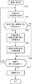


Classifications
-
- G—PHYSICS
- G06—COMPUTING OR CALCULATING; COUNTING
- G06T—IMAGE DATA PROCESSING OR GENERATION, IN GENERAL
- G06T11/00—Two-dimensional [2D] image generation
- G06T11/20—Drawing from basic elements
- G06T11/23—Drawing from basic elements using straight lines or curves
Definitions
- the present invention relates to a drawing display device and a drawing display method for displaying a drawing object on an image.
- Patent Document 1 describes a data transfer apparatus that speeds up processing time by data palette conversion and transparency processing.
- the reference data storage unit converts display data into display data when an instruction to display the same display position as that of other display data is acquired for image data stored in a predetermined address space.
- Reference data for determining whether to display the image data by overwriting is stored
- the data conversion unit converts the image data into display image data
- the transmission determination unit converts the pixel value of the display image data Then, it is determined whether or not the pixel value of the reference data matches.
- the data transfer unit transfers the display image data to the display address space when it is determined that the pixel value of the display image data matches the pixel value of the reference data.
- a border When displaying a drawing object on an image, a border may be added along the outline of the drawing object in addition to palette conversion and transparency processing. For example, when a figure is displayed on a pattern, a border is created by drawing a figure outline in a color different from that of the figure (see paragraph 0017 of Patent Document 2).
- a drawing process using a border line is performed on the contact portion (see paragraph 0015 of Patent Document 5).
- the border is drawn on the outline of the graphic displayed above, and the border is not drawn on the graphic below.
- the overlapping portion is determined by a drawing graphic description including information on elemental graphics such as line segments and dots constituting the priority order of overlapping and the graphic (see, for example, paragraph 0023 of Patent Document 4).
- the outline of the figure may be subjected to anti-aliasing processing.
- the ratio of the area occupied by each straight line to each pixel is calculated based on the vertical separation distance with respect to the straight line, and the pixel color and the frame buffer color are mixed and drawn on the display device based on the occupation ratio (Patent Document 3). (See paragraphs 0032-0044).
- the bordering is generally performed by determining the edge of the drawing object using a CPU (Central Processing Unit) or a GPU (Graphics Processing Unit) and converting the edge pixels.
- the graphic and image rendering processing is performed by dedicated hardware (see Patent Document 6), but when drawing a figure, the figure outline is drawn thickly to create a border.
- JP 2007-80106 A Japanese Patent Laid-Open No. 06-110442 Japanese Patent Application Laid-Open No. 06-274641 JP 10-049690 A JP-A-10-111955 Japanese National Patent Publication No. 11-505644
- the present invention has been made in view of the above-described circumstances, and an object of the present invention is to speed up a drawing process when a drawing object is framed and displayed on an image.
- a drawing display device provides: A priority order acquisition unit that acquires priority order information indicating the order of display of drawing objects displayed in one image; A setting unit that sets the priority of the drawing object to which the pixel belongs to each pixel of the drawing object with reference to the priority information; An edge determination unit that determines the target pixel as an edge pixel when there is a pixel having a higher priority than the target pixel in a search area of a predetermined range including the target pixel of interest in the image; A replacement unit that replaces the pixel determined to be the border pixel by the border determination unit with a pixel of a predetermined border color; It is characterized by providing.
- a drawing display method includes: A priority order acquisition step of acquiring priority order information indicating the order of display of drawing objects to be displayed in one image; A setting step of referring to the priority information and setting the priority of the drawing object to which the pixel belongs to each pixel of the drawing object; An edge determination step for determining the target pixel as an edge pixel when there is a pixel having a higher priority than the target pixel in a search area of a predetermined range including the target pixel of interest in the image; A replacement step of replacing the pixel determined as the border pixel in the border determination step with a pixel of a predetermined border color; It is characterized by providing.
- the drawing process when a plurality of drawing objects are bordered and displayed on one image, the drawing process can be accelerated.
- FIG. 2A It is a block diagram which shows the structural example of the drawing display apparatus which concerns on Embodiment 1 of this invention. It is a figure which shows the example of the drawing object without a border. It is a figure which shows the border of the drawing object of FIG. 2A. It is a figure which shows the state which attached the border to the drawing object of FIG. 2A. It is a figure which shows the example of the drawing object which has an overlapping part without a border. It is a figure which shows the example of the drawing object which has the overlapping part which determined the boundary of a background and an object, and added the border. It is a figure which shows the example which adds a border to the drawing object arrange
- FIG. 6 is a diagram illustrating an example of a search area according to Embodiment 1.
- FIG. 6 is a flowchart illustrating an example of a drawing operation according to the first embodiment.
- 6 is a flowchart showing an example of an operation of border display according to the first embodiment.
- It is a block diagram which shows the structural example of the drawing display apparatus which concerns on Embodiment 2 of this invention.
- It is a figure which shows the example of the weighted search area
- FIG. 10 is a flowchart showing an example of an operation of border display according to the second embodiment.
- 12 is a flowchart illustrating an example of an operation of border display according to the third embodiment.
- FIG. 1 is a block diagram showing a configuration example of a drawing display apparatus according to Embodiment 1 of the present invention.
- the drawing display device 1 of the present invention is a device including a monitor 16 for displaying an image such as the terminal device 10, reads a drawing object from the video memory 13, generates image data with a border on the drawing object, and generates a monitor 16. To display. Whether the drawing object is to be trimmed can be set from a CPU (Central Processing Unit) 11 or a GPU (Graphics Processing Unit) 12.
- CPU Central Processing Unit
- GPU Graphics Processing Unit
- the terminal device 10 includes a CPU 11, a GPU 12, a video memory 13, a display control circuit 15, and a monitor 16.
- the GPU 12, the video memory 13, and the display control circuit 15 are connected to the CPU 11 via the internal bus 14.
- the CPU 11 controls the entire terminal device 10.
- the CPU 11 selects an image file to be displayed on the monitor 16 and instructs the GPU 12.
- the GPU 12 expands a rendering object of a raster object or a vector object included in the commanded image file as pixel data constituting an image in the video memory 13.
- the display control circuit 15 reads out the pixel data from the video memory 13, generates image data with a border on the drawing object, and displays the image data on the monitor 16.
- the drawing display device 1 includes a GPU 12 and a display control circuit 15.
- the GPU 12 includes a priority setting unit 2.
- the display control circuit 15 includes a data reading unit 3, a border determination unit 4, and a replacement unit 5.
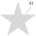
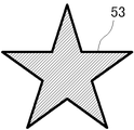
- FIG. 2A to 2C are diagrams showing an example of the border of a drawing object.
- FIG. 2A shows an example of a drawing object without a border.
- FIG. 2B shows a border of the drawing object of FIG. 2A.
- FIG. 2C shows a state in which the drawing object of FIG. 2A is trimmed.
- the CPU 11 or the GPU 12 may attach the border 52 as shown in FIG. 2B to the drawing object 51 as shown in FIG. 2A to obtain the bordered drawing object 53 as shown in FIG. 2C.
- the time for drawing the border may be equal to or longer than the time for drawing the borderless drawing object, and the drawing time increases due to the border.
- the drawing display device 1 reads out the pixel data from the video memory 13 and at the same time attaches a border.
- the drawing display device 1 includes a GPU 12, a priority order setting unit 2, a data reading unit 3, an edge determination unit 4, and a replacement unit 5.
- the GPU 12 obtains drawing object priority information from the CPU 11 and develops (draws) the drawing object in the video memory 13 in accordance with the drawing object priority.
- the priority order information is included in the image file.
- the drawing objects are developed in the video memory 13 in order from the lowest priority. In the overlapping part of the drawing objects, the pixels of the drawing object having a higher priority are overwritten, and the drawing objects are displayed on the image according to the priority.
- the priority setting unit 2 sets the priority of the drawing object to which the pixel belongs to each pixel of the drawing object. That is, each pixel data includes priority order data of a drawing object to which the pixel belongs. Since the pixel data is overwritten in order from the lower priority, the priority of the drawing object to which the pixel to be finally displayed belongs is set.
- the method of developing the drawing object in the video memory 13 is not limited to the method described above.
- the priority order of the pixels already written and the priority order of the pixels to be drawn may be compared, and the drawing may be overwritten if it is higher and not written if it is lower.
- the priority order of the drawing object to which the displayed pixel belongs may be set to that pixel.
- the priority order of the pixel data may be stored by expanding the bits of the pixel data, or may be stored using a part of the bits of the existing pixel data. For example, when RGBA transparency (A) information is not used for image display, bits assigned to transparency can be used for storing priority.
- RGBA transparency (A) information is not used for image display, bits assigned to transparency can be used for storing priority.
- the data reading unit 3 reads the pixel data from the video memory 13 and sends it to the border determination unit 4. As described above, priority order data indicating the display order of the drawing objects is added to the pixel data. The boundary where the drawing object is displayed can be identified from the priority order of the pixel data.
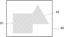
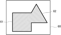
- 3A to 3C are diagrams showing examples of drawing objects having overlapping portions.
- a square drawing object 61 and a triangular drawing object 62 are arranged in the background 60.
- the background 60 is also a drawing object.
- the background 60 has the lowest priority and is arranged on the rearmost surface, then the rectangular drawing object 61 has the highest priority, and the triangular drawing object 62 has the highest priority. It can be said that the lower priority is arranged on the back side of the image, and the higher priority is arranged on the front side of the image. If the border of the background and the object is simply determined and the border is added to the drawing object of FIG. 3A, the border is not added to the border of the overlapping portion of the square drawing object 61 and the triangular object 62 as shown in FIG. 3B. .
- priority order information is added to pixel data when an object is drawn.
- a border is added not only to the boundary between the background and the object but also to the periphery of the drawing object having a high priority in the overlapping portion of the drawing objects.
- a triangular drawing is placed on the square drawing object 61 as shown in FIG. 3C.
- a border is added to the triangular drawing object 62 arranged in front of the higher priority in the overlapping portion.
- the border determination unit 4 in FIG. 1 scans a search area within a predetermined range including the target pixel by moving the search area so that pixels included in the image to be displayed are sequentially set as the target pixel, and is included in the search area. It is determined using the pixel data whether the target pixel is a border pixel. The border determination unit 4 determines that the target pixel is a border pixel when there is a pixel having a higher priority than the target pixel in a search area within a predetermined range including the target pixel of interest.
- the search area is a closed area (single connection) that includes the target pixel and that the pixels continue vertically and horizontally (there are no separated pixels).
- the size of the search area is set according to the width of the border.
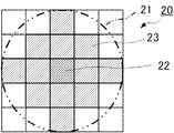
- FIG. 4 is a diagram illustrating an example of a search area according to the first embodiment.
- the pixel 22 with hatching intersecting at the center indicates the position of the target pixel.
- the search area 20 is, for example, a pixel included in a circle 21 whose diameter is a size obtained by adding one pixel to the width of the border centering on the target pixel (pixel 22).
- the search area 20 in FIG. 4 is an example when the border width is 4 pixels. In the example of FIG. 4, twelve pixels 23 with hatched hatching constitute the search area 20.
- the border determination unit 4 moves the search area 20 in the image so that the pixels of the image to be displayed are sequentially set as target pixels (pixels 22), and the search area 20 (pixels 23) for each target pixel (pixel 22). Whether or not the target pixel (pixel 22) is a border pixel is determined based on whether or not there is a pixel having a higher priority than the target pixel. If there is a pixel having a higher priority than the target pixel (pixel 22) in the search area, the target pixel (pixel 22) is determined as a border pixel. If there is no pixel having a higher priority than the target pixel (pixel 22) in the search area, the target pixel is a non-framing pixel.
- the border judgment unit 4 in FIG. 1 sends the result of border judgment to the replacement unit 5.
- the replacement unit 5 replaces the border pixel with the pixel of the predetermined border color and causes the monitor 16 to display the image.
- the border color is not limited to one color for the entire image. For example, a different color may be used for each drawing object. Further, a different color may be used for each region in the image. In addition, gradation can be added with one drawing object.
- the display control circuit 15 can be composed of, for example, a shift register of pixel data corresponding to the search area and a circuit that calculates from each data of the shift register. For example, it is possible to determine whether or not the target pixel is a border pixel by comparing the priority order of the data of the target pixel of the shift register with other data and taking a logical sum.
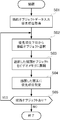
- FIG. 5 is a flowchart showing an example of the drawing operation according to the first embodiment.
- the GPU 12 inputs the drawing object data and acquires the priority order of the drawing objects (step S01).
- a drawing object is selected from a drawing object having a lower priority (step S02).
- the selected drawing object is developed (drawn) in the video memory 13 (step S03).
- the priority order setting unit 2 sets the priority order of the drawing object to the drawn pixels (step S04).
- step S05 If there is a drawing object to be developed in the video memory 13 (step S05; YES), the process returns to step S02, selects a lower one of the remaining drawing objects, and repeats the processing up to step S04. If there is no drawing object to be developed (step S05; NO), the drawing process is terminated.
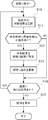
- FIG. 6 is a flowchart showing an example of the border display operation according to the first embodiment.
- the data reading unit 3 of the display control circuit 15 selects a target pixel in the image from the video memory 13 (step S10). For example, pixel data corresponding to the search area including the target pixel is read into a shift register corresponding to the search area 20 as shown in FIG.
- step S11 If there is a pixel having a higher priority than the target pixel in the search area (step S11; YES), the border determination unit 4 sets the target pixel as a border pixel (step S12). Then, the replacement unit 5 replaces the color value of the target pixel (border pixel) with the determined border color (step S13). If there is no pixel having a higher priority than the target pixel in the search area (step S11; NO), step S12 and step S13 are skipped.
- step S14 If there is a remaining pixel to be selected as the target pixel in the image (step S14; YES), the process returns to step S10 to select the next target pixel. For example, the next pixel data is read into each row of the aforementioned shift register. Then, the above process is repeated. If there is no remaining pixel to be selected as the target pixel in the image (step S14; NO), an image in which the border pixel is replaced is displayed on the monitor 16 (step S15).
- each pixel is mechanically determined in the search area using the priority information of the drawing objects, a plurality of drawing objects are trimmed.
- the drawing process can be speeded up.
- a border can be added to a drawing object having a high priority in a portion where drawing objects overlap.
- the drawing display device 1 of the first embodiment it is possible to eliminate the need for the CPU 11 or the GPU 12 to draw a border for an object drawing that requires a border. Thereby, the effect of reducing the load on the CPU 11 and the GPU 12 is obtained. Although there is no change in the used memory bandwidth from the drawing display device 1 to the video memory 13 according to the first embodiment, the access to the video memory 13 from the CPU 11 or the GPU 12 is reduced. The effect to raise is also acquired.
- the border width is 4 pixels, but the border width can be changed by changing the size of the search area 20.
- the search area 20 is not limited to a symmetric shape with the target pixel as the center as shown in FIG. The search area may not be circular. If the search area is biased with respect to the target pixel, a biased border can be added to the drawing object.
- the configuration of the drawing display device 1 is not limited to the GPU 12 and the display control circuit 15.
- the priority setting unit 2 and the display control circuit 15 can be used as the drawing display device 1 by separating the processing for developing the drawing object in the video memory 13 by the GPU 12 and the processing for setting the priority setting for each pixel.
- the display control circuit 15 can be incorporated into the GPU 12 so that the GPU 12 can also serve as the drawing display device 1.
- Embodiment 2 In Embodiment 1, since the border color is always a fixed color, jaggy may be noticeable depending on the drawing object.
- the border color and the blending process are applied to the border color in accordance with the occupancy rate of the search area in the target drawing object or the drawing object having a high priority.
- FIG. 7 is a block diagram showing a configuration example of a drawing display apparatus according to Embodiment 2 of the present invention.
- the border determination unit 4 includes an occupation rate calculation unit 6.
- the occupancy rate calculation unit 6 calculates the occupancy rate of the search area of the drawing object having a higher priority with respect to the target pixel, using the weighting coefficient assigned to each pixel position in the search area.
- the replacement unit 5 replaces the border pixel with a pixel having a color value obtained by multiplying the border color by the occupation ratio.
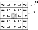
- FIG. 8 is a diagram illustrating an example of a weighted search area according to the second embodiment.
- a weighting coefficient is set at the position of the pixel included in the search area 24.
- a weighting coefficient of 1.0 is set for the pixel that is completely included in the position of the pixel 23 in the search area 20 of FIG. 4, that is, the distance of the border width (circle 21).
- a weighting coefficient of 0.6 or 0.2 is set according to the area partially included in the distance of the border width (a pixel is applied to the circle 21).
- the occupancy ratio calculation unit 6 uses, for example, the weighting coefficient assigned to each pixel position in the search area 24, and calculates, for example, the sum of the weighting coefficients at the positions of the pixels having higher priority than the target pixel in the search area 24. Calculate as If the target pixel is not a border pixel, there is no pixel having a higher priority than the target pixel in the search area 24, so the occupation ratio is set to zero. When the occupation ratio is not 0, the target pixel can be determined as a border pixel. In the example of FIG. 8, the occupation ratio calculation unit 6 clamps the occupation ratio to 1.0 when the total of the weighting coefficients exceeds 1.0.
- the weighting coefficient included in the search area may be normalized so that the maximum sum of the weighting coefficients at the positions of the pixels having higher priority than the target pixel is 1.
- the pixel with higher priority than the target pixel can be set to 1, and the product sum with the weighting coefficient of the search area can be used as the occupation ratio.
- the method of setting the weighting factor can be determined arbitrarily.
- the occupancy calculation method based on the sum of the weighting coefficients of the positions of the pixels having higher priority than the target pixel in the search area can be arbitrarily set.
- the first embodiment can be regarded as a special case of the second embodiment in which the weighting coefficient is set to 1, and the logical sum of products with pixels having higher priority than the target pixel is calculated as the occupation ratio.
- the replacement unit 5 replaces the border pixel with a pixel having a color value obtained by multiplying the border color by the occupation ratio. As a result, it is possible to add an anti-aliasing effect to the border.
- FIG. 9 is a flowchart showing an example of the border display operation according to the second embodiment.
- step S22 and step S23 are different from step S12 and step S13 of FIG.
- the occupation rate is calculated at the same time as setting the target pixel as a border pixel (step S22).
- the replacement unit 5 replaces the border pixel with a border color pixel and multiplies the occupation rate (step S23). Then, an image composed of drawing pixels and border pixels is displayed on the monitor 16 (step S15).
- the border color is multiplied by the occupancy ratio of the pixel having higher priority than the target pixel in the search area for the target pixel.
- jaggy can be made inconspicuous.
- FIG. 10 is a block diagram showing a configuration example of a drawing display apparatus according to Embodiment 3 of the present invention.
- the replacement unit 5 includes a border color adjusting unit 7.
- Other configurations are the same as those in the first embodiment.
- the border color adjusting unit 7 sets a color value obtained by multiplying the border color by a color value of a pixel having a high priority in the search area for the target pixel as a border color when the target pixel is replaced.
- the border color changes according to a pixel having a higher priority than the target pixel included in the search area.
- the anti-aliasing effect set when the drawing object is expanded is reflected on the border pixels.
- FIG. 11 is a flowchart showing an example of the border display operation according to the third embodiment.
- step S33 is inserted between step S12 and step S13 in FIG.
- the border color adjusting unit 7 of the replacement unit 5 sets the color value of the pixel having a high priority in the search area for the target pixel as the border color.
- the border color is adjusted so as to be the border color when the target pixel is replaced by multiplication (step S33).
- the replacement unit 5 sets the target pixel as a border pixel (step S12).
- Other operations are the same as those in the first embodiment.
- the drawing display device 1 of the third embodiment when the target pixel is set to the border color, the color value of the pixel having a higher priority order than the target pixel included in the search region is adjusted to the color value multiplied by the border color. Therefore, the anti-aliasing effect set for the pixels with high priority can be reflected in the border. As a result, killing the effect of anti-aliased pixels by bordering is avoided.
- the second embodiment and the third embodiment can be implemented together.
- a priority order acquisition unit that acquires priority order information indicating the order of display of drawing objects displayed in one image;
- a setting unit that sets the priority of the drawing object to which the pixel belongs to each pixel of the drawing object with reference to the priority information;
- An edge determination unit that determines the target pixel as an edge pixel when there is a pixel having a higher priority than the target pixel in a search area of a predetermined range including the target pixel of interest in the image;
- a replacement unit that replaces the pixel determined to be the border pixel by the border determination unit with a pixel of a predetermined border color;
- a drawing display device comprising:
- the border determination unit uses the weighting coefficient assigned to each pixel position in the search area when the search area includes a pixel having the higher priority than the target pixel in the search area. Calculate the occupancy rate according to a predetermined criterion based on the sum of the weighting coefficients of the pixel positions with higher ranks, The replacement unit replaces the target pixel with a pixel having a color value obtained by multiplying the border color by the occupation ratio calculated for the target pixel when the target pixel is determined to be the border pixel.
- the replacement unit when there is a pixel having a higher priority than the target pixel in the search area, a color obtained by multiplying the border color by a color value of the pixel having a higher priority in the search area for the target pixel.
- the drawing display device according to appendix 1 or 2, wherein the value is a border color when the target pixel is replaced.
- Appendix 4 The drawing display device according to any one of appendices 1 to 3, wherein the search area is a circle whose diameter is a size obtained by adding one pixel to the width of the border centering on the target pixel.
- a drawing display method comprising:
- the border determination step when there is a pixel having a higher priority than the target pixel in the search area, the priority of the search area is determined using a weighting coefficient assigned to each pixel position of the search area. Calculate the occupancy rate according to a predetermined criterion based on the sum of the weighting coefficients of the pixel positions with higher ranks,
- the replacement step when the target pixel is determined to be the border pixel, the target pixel is replaced with a pixel having a color value obtained by multiplying the border color by the occupation ratio calculated for the target pixel.
- Appendix 8 The drawing display method according to any one of appendices 5 to 7, wherein the search area is a circle whose diameter is a size obtained by adding one pixel to the width of the border centering on the target pixel.
Landscapes
- Physics & Mathematics (AREA)
- General Physics & Mathematics (AREA)
- Engineering & Computer Science (AREA)
- Theoretical Computer Science (AREA)
- Image Generation (AREA)
- Processing Or Creating Images (AREA)
- Editing Of Facsimile Originals (AREA)
- Controls And Circuits For Display Device (AREA)
Abstract
描画オブジェクトに縁取りを付けて画像に表示する場合に、描画処理を高速にする。GPU(12)は、1つの画像に表示する描画オブジェクトの、画像に表示する順序を示す優先順位情報を取得する。優先順位設定部(2)は、優先順位情報を参照して描画オブジェクトをビデオメモリ(13)に展開するときに、描画オブジェクトの各画素に、その画素が属する描画オブジェクトの優先順位を設定する。縁取り判定部(4)は、ビデオメモリ(13)に展開された画像の着目する対象画素を含む定めた範囲の検索領域に、対象画素よりも優先順位の高い画素がある場合に、対象画素を縁取り画素と判定する。置換部(5)は、縁取り判定部(4)で縁取り画素と判定された画素を、定めた縁取り色の画素に置き換える。
Description
本発明は、描画オブジェクトを画像に表示する描画表示装置および描画表示方法に関する。
一般に描画オブジェクトを画像に表示する場合、別の色空間に変換したり、透過色に変換してデータ転送することが行われている。例えば、特許文献1には、データのパレット変換と透過処理による処理時間を高速化するデータ転送装置が記載されている。
特許文献1のデータ転送装置では、基準データ記憶部は、所定のアドレス空間に格納された画像データに対して他の表示データと同一の表示位置への表示指示を取得した場合に、表示データに上書きし画像データを表示させるか否かを判断するための基準データを記憶し、データ変換部は、画像データを表示用画像データに変換し、透過判定部は、表示用画像データの画素値と、基準データの画素値とが一致するか否かを判定する。そして、データ転送部は、表示用画像データの画素値と基準データの画素値とが一致すると判断された場合に、表示用画像データを表示用アドレス空間に転送する。
描画オブジェクトを画像に表示するときに、パレット変換や透過処理以外に、描画オブジェクトの輪郭に沿って、縁取りを付けることがある。例えば、模様上に図形を表示する場合に、図形と異なる色で図形輪郭線を太く描いて縁取りを作成する(特許文献2段落0017参照)。
図形どうしが接触して重なり部分を有する場合に、接触部分に対して縁取り線を用いた描画処理を行なう(特許文献5段落0015参照)。重なり部分では、上に表示される図形の輪郭線に縁取りを描画し、下になる図形には縁取りを描画しないことになる。重なり部分は、重なりの優先順位および図形を構成する線分や点などの要素図形の情報を含む描画図形記述で判断する(例えば特許文献4段落0023参照)。
また、図形の輪郭はアンチエイリアシング処理が施される場合がある。例えば、直線に対する垂直離間距離に基づき直線が各画素に占める面積の割合(占有率)を算出し、占有率に基づき画素の色とフレームバッファの色を混ぜ合わせ表示装置に描画する(特許文献3段落0032~0044参照)。
縁取りはCPU(Central Processing Unit)またはGPU(Graphics Processing Unit)を用いて、描画オブジェクトの縁を判定して、縁の画素を変換することが一般的である。グラフィックおよび画像レンダリング処理が専用ハードウエアで行われる場合もあるが(特許文献6参照)、図形を描画するときに図形輪郭線を太く描いて縁取りを作成することは変わりがない。
描画オブジェクトに縁取りを付けて画像に表示する場合、描画オブジェクトの描画に加えて輪郭に沿って縁取りを描画する必要があり、描画処理時間が長くなるという課題があった。描画時間短縮のために表示制御回路で縁取りを付加する方法では、複数のオブジェクトが重なる部分の縁取りを正しく付加できない場合がある。
本発明は上述のような事情に鑑みてなされたもので、描画オブジェクトに縁取りを付けて画像に表示する場合に、描画処理を高速にすることを目的とする。
本発明の第1の観点に係る描画表示装置は、
1つの画像に表示する描画オブジェクトの、前記画像に表示する順序を示す優先順位情報を取得する優先順位取得部と、
前記優先順位情報を参照して前記描画オブジェクトの各画素に、その画素が属する前記描画オブジェクトの優先順位を設定する設定部と、
前記画像の着目する対象画素を含む定めた範囲の検索領域に、前記対象画素よりも前記優先順位の高い画素がある場合に、前記対象画素を縁取り画素と判定する縁取り判定部と、
前記縁取り判定部で前記縁取り画素と判定された画素を、定めた縁取り色の画素に置き換える置換部と、
を備えることを特徴とする。
1つの画像に表示する描画オブジェクトの、前記画像に表示する順序を示す優先順位情報を取得する優先順位取得部と、
前記優先順位情報を参照して前記描画オブジェクトの各画素に、その画素が属する前記描画オブジェクトの優先順位を設定する設定部と、
前記画像の着目する対象画素を含む定めた範囲の検索領域に、前記対象画素よりも前記優先順位の高い画素がある場合に、前記対象画素を縁取り画素と判定する縁取り判定部と、
前記縁取り判定部で前記縁取り画素と判定された画素を、定めた縁取り色の画素に置き換える置換部と、
を備えることを特徴とする。
本発明の第2の観点に係る描画表示方法は、
1つの画像に表示する描画オブジェクトの、前記画像に表示する順序を示す優先順位情報を取得する優先順位取得ステップと、
前記優先順位情報を参照して前記描画オブジェクトの各画素に、その画素が属する前記描画オブジェクトの優先順位を設定する設定ステップと、
前記画像の着目する対象画素を含む定めた範囲の検索領域に、前記対象画素よりも前記優先順位の高い画素がある場合に、前記対象画素を縁取り画素と判定する縁取り判定ステップと、
前記縁取り判定ステップで前記縁取り画素と判定された画素を、定めた縁取り色の画素に置き換える置換ステップと、
を備えることを特徴とする。
1つの画像に表示する描画オブジェクトの、前記画像に表示する順序を示す優先順位情報を取得する優先順位取得ステップと、
前記優先順位情報を参照して前記描画オブジェクトの各画素に、その画素が属する前記描画オブジェクトの優先順位を設定する設定ステップと、
前記画像の着目する対象画素を含む定めた範囲の検索領域に、前記対象画素よりも前記優先順位の高い画素がある場合に、前記対象画素を縁取り画素と判定する縁取り判定ステップと、
前記縁取り判定ステップで前記縁取り画素と判定された画素を、定めた縁取り色の画素に置き換える置換ステップと、
を備えることを特徴とする。
本発明によれば、複数の描画オブジェクトに縁取りを付けて1つの画像に表示する場合に、描画処理を高速にすることができる。
以下、本発明の実施の形態について図面を参照して説明する。なお、図中、同一または相当する部分には同じ符号を付す。
(実施の形態1)
図1は、本発明の実施の形態1に係る描画表示装置の構成例を示すブロック図である。本発明の描画表示装置1は、端末装置10などの画像を表示するモニタ16を備える装置において、ビデオメモリ13から描画オブジェクトを読み出し、描画オブジェクトに縁取りを付けた画像データを生成して、モニタ16に表示する。描画オブジェクトに縁取りを付けるかどうかは、CPU(Central Processing Unit)11またはGPU(Graphics Processing Unit)12から設定できる。
図1は、本発明の実施の形態1に係る描画表示装置の構成例を示すブロック図である。本発明の描画表示装置1は、端末装置10などの画像を表示するモニタ16を備える装置において、ビデオメモリ13から描画オブジェクトを読み出し、描画オブジェクトに縁取りを付けた画像データを生成して、モニタ16に表示する。描画オブジェクトに縁取りを付けるかどうかは、CPU(Central Processing Unit)11またはGPU(Graphics Processing Unit)12から設定できる。
例えば、端末装置10は、CPU11、GPU12、ビデオメモリ13、表示制御回路15およびモニタ16から構成される。GPU12、ビデオメモリ13および表示制御回路15は、内部バス14を介してCPU11に接続する。CPU11は、端末装置10全体の制御を司る。CPU11は例えば、モニタ16に表示する画像ファイルを選択してGPU12に指令する。GPU12は、指令された画像ファイルに含まれるラスタオブジェクトまたはベクトルオブジェクトの描画オブジェクトをビデオメモリ13に画像を構成する画素データとして展開する。表示制御回路15は、ビデオメモリ13から画素データを読み出し、描画オブジェクトに縁取りを付けた画像データを生成して、モニタ16に表示する。
本実施の形態において描画表示装置1は、GPU12と表示制御回路15から構成される。GPU12は、優先順位設定部2を含む。表示制御回路15は、データ読み出し部3、縁取り判定部4および置換部5を含む。
図2A~図2Cは、描画オブジェクトの縁取りの例を示す図である。図2Aは、縁取りのない描画オブジェクトの例を示す。図2Bは、図2Aの描画オブジェクトの縁取りを示す。図2Cは、図2Aの描画オブジェクトに縁取りを付けた状態を示す。
図2Aに示すような描画オブジェクト51に図2Bのような縁取り52を付けて、図2Cに示す縁取り付描画オブジェクト53にするのは、CPU11またはGPU12で行うことも可能である。しかし、縁取りを描画する時間は縁なしの描画オブジェクトを描画する時間と同等以上になることもあり、縁取りがあることで描画時間が増大する。本実施の形態では、描画表示装置1で、ビデオメモリ13から画素データを読み出すと同時に、縁取りを付ける。
描画表示装置1は、GPU12、優先順位設定部2、データ読み出し部3、縁取り判定部4、および、置換部5を備える。GPU12は、描画オブジェクトの優先順位情報をCPU11から取得し、描画オブジェクトの優先順位にしたがって、描画オブジェクトをビデオメモリ13に展開(描画)する。例えば、優先順位情報は、画像ファイルに含まれている。例えば、描画オブジェクトは下位の優先順位から順にビデオメモリ13に展開される。描画オブジェクトどうしの重なり部分では、優先順位の高い描画オブジェクトの画素が上書きされて、優先順位にしたがって描画オブジェクトが画像に表示される。
優先順位設定部2は、GPU12で描画オブジェクトをビデオメモリ13に展開(描画)するときに、描画オブジェクトの各画素に、その画素が属する描画オブジェクトの優先順位を設定する。すなわち、各画素データはその画素が属する描画オブジェクトの優先順位のデータを含む。画素データは、下位の優先順位から順に上書きされるので、最終的に表示される画素が属する描画オブジェクトの優先順位が設定される。
描画オブジェクトをビデオメモリ13に展開する手法は、上述の方法に限らない。描画オブジェクトをビデオメモリ13に展開するときに、すでに書き込まれている画素の優先順位と描画する画素の優先順位を比較して、描画する方が上位なら上書き、下位なら書き込まないという方法でもよい。いずれにしろ、表示される画素が属する描画オブジェクトの優先順位が、その画素に設定されればよい。
画素データの優先順位は、画素データのビットを拡張して記憶させてもよいし、既存の画素データのビットの一部を利用して記憶させてもよい。例えば、画像表示にRGBAの透明度(A)の情報を用いない場合に、透明度に割り当てられたビットを優先順位の記憶に用いることができる。
データ読み出し部3は、ビデオメモリ13から画素データを読み出し、縁取り判定部4に送る。上述のとおり画素データは、描画オブジェクトの表示する順序を示す優先順位のデータが付加されている。画素データの優先順位から、描画オブジェクトの表示される境界を識別することができる。
図3A~図3Cは、重なり部分を有する描画オブジェクトの例を示す図である。図3Aに示す縁取りのない元の画像は、背景60の中に、四角の描画オブジェクト61と、三角の描画オブジェクト62が配置されている。背景60も1つの描画オブジェクトである。図3の例では、背景60が最も優先順位が低く最背面に配置され、次いで四角の描画オブジェクト61の優先順位であり、三角の描画オブジェクト62の優先順位が最も高い。優先順位が低い方が画像の背面側、優先順位が高い方が画像の前面側に配置されるとも言える。図3Aの描画オブジェクトに単純に背景とオブジェクトの境界を判定して縁取りを付加すると、図3Bに示すように、四角の描画オブジェクト61と三角のオブジェクト62が重複した部分の境界に縁取りが付加されない。
このような状況を回避するために、本実施の形態1ではオブジェクト描画時に画素データに優先順位情報を追加しておく。そして、背景とオブジェクトの境界だけでなく、描画オブジェクトの重なり部分で優先順位が高い描画オブジェクトの周囲にも縁取りを付加する。図3Aの例で、四角の描画オブジェクト61に低い優先順位、三角の描画オブジェクト62に高い優先順位が付けられている場合、図3Cに示すように、四角の描画オブジェクト61の上に三角の描画オブジェクト62が重複する場合に、重複する部分では優先順位の高い前面に配置される三角の描画オブジェクト62に縁取りを付加する。
図1の縁取り判定部4は、対象画素を含む定めた範囲の検索領域で、表示する画像に含まれる画素を順次対象画素にするように検索領域を移動してスキャンし、検索領域に含まれる画素データを用いて、対象画素が縁取り画素か否かを判定する。縁取り判定部4は、着目する対象画素を含む定めた範囲の検索領域に、対象画素よりも優先順位の高い画素がある場合に、その対象画素を縁取り画素と判定する。
検索領域は、対象画素を含み画素が縦横に連続する(離隔した画素がない)閉じた領域(単連結)である。検索領域の大きさは、縁取りの幅に応じて設定される。
図4は、実施の形態1に係る検索領域の例を示す図である。中心の交差するハッチングを付した画素22は、対象画素の位置を示す。検索領域20は、例えば、対象画素(画素22)を中心として縁取りの幅に1画素を加えた大きさを直径とする円21に含まれる画素である。図4の検索領域20は、縁取り幅が4ピクセルの場合の例である。図4の例では、斜線のハッチングを付した12個の画素23が検索領域20を構成する。
縁取り判定部4は、表示する画像の画素を順次対象画素(画素22)とするように、検索領域20を画像の中で移動して、対象画素(画素22)ごとに検索領域20(画素23の位置)に対象画素より優先順位の高い画素があるか否かによって、対象画素(画素22)が縁取り画素か否かを判定する。検索領域のなかに対象画素(画素22)より優先順位の高い画素がある場合に、対象画素(画素22)を縁取り画素と判定する。検索領域の中に、対象画素(画素22)よりも優先順位の高い画素がなければ、その対象画素は非縁取り画素である。
図1の縁取り判定部4は、縁取り判定した結果を置換部5に送る。置換部5は、定めた縁取り色の画素に縁取り画素を置き換えて、画像をモニタ16に表示させる。縁取り色は、画像全体で1色とは限らない。例えば、描画オブジェクトごとに異なる色であってもよい。また、画像内の領域ごとに異なる色でもよい。その他、1つの描画オブジェクトでグラデーションを付けることもできる。
表示制御回路15は、例えば、検索領域に相当する画素データのシフトレジスタと、シフトレジスタの各データから演算する回路で構成することができる。例えば、シフトレジスタの対象画素の位置のデータとその他のデータの優先順位を比較し、論理和をとることによって、対象画素が縁取り画素か否かを判定することができる。
図5は、実施の形態1に係る描画の動作の一例を示すフローチャートである。GPU12は、描画オブジェクトのデータを入力し、描画オブジェクトの優先順位を取得する(ステップS01)。描画オブジェクトの優先順位が下位のものから、描画オブジェクトを選択する(ステップS02)。選択した描画オブジェクトをビデオメモリ13に展開(描画)する(ステップS03)。同時に、優先順位設定部2は、描画した画素にその描画オブジェクトの優先順位を設定する(ステップS04)。
ビデオメモリ13に展開すべき描画オブジェクトがあれば(ステップS05;YES)、ステップS02に戻って、残りの描画オブジェクトのうち下位のものを選択して、ステップS04までの処理を繰り返す。展開すべき描画オブジェクトがなくなれば(ステップS05;NO)、描画処理を終了する。
図6は、実施の形態1に係る縁取り表示の動作の一例を示すフローチャートである。表示制御回路15のデータ読み出し部3は、ビデオメモリ13から、画像内の対象画素を選択する(ステップS10)。例えば、図4に示すような検索領域20に相当するシフトレジスタに、対象画素を含む検索領域に対応する画素データを読み込む。
縁取り判定部4は、検索領域に対象画素より高い優先順位の画素があれば(ステップS11;YES)、対象画素を縁取り画素に設定する(ステップS12)。そして、置換部5は、その対象画素(縁取り画素)の色値を定められた縁取り色に置き換える(ステップS13)。検索領域に対象画素より優先順位の高い画素がなければ(ステップS11;NO)、ステップS12およびステップS13をスキップする。
画像に対象画素として選択すべき残りの画素があれば(ステップS14;YES)、ステップS10に戻って、次の対象画素を選択する。例えば、前述のシフトレジスタの各行に次の画素データを読み込む。そして、以上の処理を繰り返す。画像に対象画素として選択すべき残りの画素がなければ(ステップS14;NO)、縁取り画素を置き換えた画像をモニタ16に表示する(ステップS15)。
以上説明したように、本実施の形態1の描画表示装置1によれば、描画オブジェクトの優先順位情報を用いて、検索領域で各画素を機械的に判定するので、複数の描画オブジェクトに縁取りを付けて1つの画像に表示する場合に、描画処理を高速にすることができる。また、描画オブジェクトの重複する部分では優先順位の高い描画オブジェクトに縁取りを付加することができる。
実施の形態1の描画表示装置1によれば、縁取りが必要なオブジェクト描画に対してCPU11やGPU12が縁取りを描画する必要をなくすことができる。これにより、CPU11やGPU12の負荷低減という効果が得られる。本実施の形態1による描画表示装置1からのビデオメモリ13への使用メモリ帯域に変化はないが、CPU11やGPU12からのビデオメモリ13へのアクセスが減るので、ビデオメモリ13に対するメモリバス使用効率を上げる効果も得られる。
図4の例では、縁取り幅を4ピクセルとしたが、検索領域20の大きさを変えれば、縁取り幅を変えることができる。また検索領域20は、図4に示すような対象画素を中心とする対称な形とは限らない。検索領域は、円形でなくてもよい。対象画素に対して検索領域を偏らせれば、描画オブジェクトに対して偏った縁取りを付加することができる。
描画表示装置1の構成は、GPU12と表示制御回路15には限らない。GPU12で描画オブジェクトをビデオメモリ13に展開する処理と、各画素に優先順位設定を設定する処理を分けて、優先順位設定部2と表示制御回路15を描画表示装置1とすることができる。また、GPU12に表示制御回路15を取り込んでGPU12が描画表示装置1を兼ねるようにすることもできる。
(実施の形態2)
実施の形態1では、縁取り色は常に固定色であるため、描画オブジェクトによってはジャギーが目立つ場合がある。実施の形態2では、対象の描画オブジェクトまたは優先順位の高い描画オブジェクトにおける検索領域の占有率に応じて、縁取り色に対して置き換え前の色とブレンド処理を施す。
実施の形態1では、縁取り色は常に固定色であるため、描画オブジェクトによってはジャギーが目立つ場合がある。実施の形態2では、対象の描画オブジェクトまたは優先順位の高い描画オブジェクトにおける検索領域の占有率に応じて、縁取り色に対して置き換え前の色とブレンド処理を施す。
図7は、本発明の実施の形態2に係る描画表示装置の構成例を示すブロック図である。実施の形態2に係る描画表示装置1では、縁取り判定部4は占有率算出部6を含む。その他の構成は、実施の形態1と同様である。占有率算出部6は、検索領域の各画素位置に付与された重み付け係数を用いて、対象画素に対して優先順位の高い描画オブジェクトの検索領域の占有率を算出する。置換部5は、縁取り画素を、縁取り色に占有率を乗じた色値の画素に置き換える。
図8は、実施の形態2に係る重み付き検索領域の例を示す図である。実施の形態2では、検索領域24に含まれる画素の位置に重み付け係数が設定されている。図8の検索領域24では、図4の検索領域20の画素23の位置、すなわち縁取り幅の距離(円21)に完全に含まれる画素に重み付け係数1.0が設定されている。また、縁取り幅の距離内に一部含まれる(円21に画素がかかる)面積に応じて、0.6または0.2の重み付け係数が設定されている。
占有率算出部6は、検索領域24の各画素位置に付与された重み付け係数を用いて、例えば、検索領域24のうち、対象画素より優先順位の高い画素の位置の重み付け係数の合計を占有率として算出する。対象画素が縁取り画素でなければ、検索領域24に対象画素より優先順位の高い画素がないので、占有率を0とする。占有率が0でない場合に、その対象画素を縁取り画素と判定することができる。図8の例では、占有率算出部6は、重み付け係数の合計が1.0を超える場合には、占有率を1.0にクランプする。
検索領域に含まれる重み付け係数を、対象画素より優先順位の高い画素の位置の重み付け係数の合計の最大値が1になるように、正規化してもよい。その場合、対象画素より高い優先順位の画素を1として、検索領域の重み付け係数との積和を占有率とすることができる。
重み付け係数の設定の仕方は任意に決めることができる。また、検索領域の対象画素より優先順位の高い画素の位置の重み付け係数の合計、に基づく占有率の算出方法は、任意に設定することができる。実施の形態1は、重み付け係数を1として、対象画素より優先順位の高い画素との積の論理和を占有率として算出する、実施の形態2の特殊な場合と見ることができる。
置換部5は、縁取り画素を、縁取り色に占有率を乗じた色値の画素に置き換える。その結果、縁取りにアンチエイリアス効果を付けることが可能である。
図9は、実施の形態2に係る縁取り表示の動作の一例を示すフローチャートである。図9に示す縁取り表示の動作のうち、ステップS22およびステップS23が、図6のステップS12およびステップS13と異なる。実施の形態2では、対象画素を縁取り画素に設定すると同時に、占有率を算出する(ステップS22)。また、置換部5は、縁取り画素を縁取り色の画素に置換して、占有率を乗算する(ステップS23)。そして、描画画素および縁取り画素からなる画像をモニタ16に表示する(ステップS15)。
以上説明したように、実施の形態2の描画表示装置1によれば、対象画素に対して、検索領域における対象画素より優先順位の高い画素の占有率を縁取り色に乗ずるので、実施の形態1の効果に加えて、ジャギーを目立たなくさせることができる。
(実施の形態3)
実施の形態3では、描画オブジェクトをビデオメモリ13に展開するときに設定したアンチエイリアスの効果を、縁取り画素に反映する。実施の形態3では、描画オブジェクトが画素に占める割合に応じて、その画素の色値が設定されていることを想定している。
実施の形態3では、描画オブジェクトをビデオメモリ13に展開するときに設定したアンチエイリアスの効果を、縁取り画素に反映する。実施の形態3では、描画オブジェクトが画素に占める割合に応じて、その画素の色値が設定されていることを想定している。
図10は、本発明の実施の形態3に係る描画表示装置の構成例を示すブロック図である。実施の形態3に係る描画表示装置1では、置換部5は縁取り色調節部7を含む。その他の構成は、実施の形態1と同様である。縁取り色調節部7は、対象画素に対する検索領域の優先順位の高い画素の色値を縁取り色に乗じた色値を、その対象画素を置き換える場合の縁取り色とする。縁取り色は、検索領域に含まれる対象画素より優先順位の高い画素に応じて変化する。その結果、描画オブジェクトを展開するときに設定したアンチエイリアスの効果が、縁取り画素に反映される。
優先順位の高い画素のうち、どの画素の色値を縁取り色に乗ずるかは、適宜決めることができる。例えば、検索領域に含まれる対象画素より優先順位の高い画素のうち、対象画素に距離が最も近い画素を選択して、その色値を縁取り色に乗じて、対象画素を置き換える場合の縁取り色とすることができる。または、検索領域に含まれる対象画素より優先順位の高い画素のうち、最も色値の低い画素を選択して、その色値を縁取り色に乗じて、対象画素を置き換える場合の縁取り色とすることができる。あるいは、例えば、検索領域に含まれる対象画素より優先順位の高い画素の色値の平均値を用いてもよい。
図11は、実施の形態3に係る縁取り表示の動作の一例を示すフローチャートである。図11に示す縁取り表示の動作では、図6のステップS12とステップS13の間に、ステップS33が挿入されている。実施の形態3では、置換部5の縁取り色調節部7は、対象画素が縁取り画素に設定された場合(ステップS12)、対象画素に対する検索領域の優先順位の高い画素の色値を縁取り色に乗じて、その対象画素を置き換える場合の縁取り色とするように、縁取り色を調節する(ステップS33)。置換部5は、対象画素を縁取り画素に設定する(ステップS12)。その他の動作は、実施の形態1と同様である。
実施の形態3の描画表示装置1によれば、対象画素を縁取り色にする場合に、検索領域に含まれる対象画素より優先順の高い画素の色値を縁取り色に乗じた色値に調節するので、優先順位の高い画素に設定されたアンチエイリアスの効果を、縁取りに反映することができる。その結果、アンチエイリアス処理された画素に対して、縁取りによってその効果を殺ぐことが回避される。なお、実施の形態2と実施の形態3を合わせて実施することもできる。
上述の実施の形態の一部または全部は、以下の付記のようにも記載され得るが、以下には限られない。
(付記1)
1つの画像に表示する描画オブジェクトの、前記画像に表示する順序を示す優先順位情報を取得する優先順位取得部と、
前記優先順位情報を参照して前記描画オブジェクトの各画素に、その画素が属する前記描画オブジェクトの優先順位を設定する設定部と、
前記画像の着目する対象画素を含む定めた範囲の検索領域に、前記対象画素よりも前記優先順位の高い画素がある場合に、前記対象画素を縁取り画素と判定する縁取り判定部と、
前記縁取り判定部で前記縁取り画素と判定された画素を、定めた縁取り色の画素に置き換える置換部と、
を備えることを特徴とする描画表示装置。
1つの画像に表示する描画オブジェクトの、前記画像に表示する順序を示す優先順位情報を取得する優先順位取得部と、
前記優先順位情報を参照して前記描画オブジェクトの各画素に、その画素が属する前記描画オブジェクトの優先順位を設定する設定部と、
前記画像の着目する対象画素を含む定めた範囲の検索領域に、前記対象画素よりも前記優先順位の高い画素がある場合に、前記対象画素を縁取り画素と判定する縁取り判定部と、
前記縁取り判定部で前記縁取り画素と判定された画素を、定めた縁取り色の画素に置き換える置換部と、
を備えることを特徴とする描画表示装置。
(付記2)
前記縁取り判定部は、前記検索領域内に前記対象画素よりも前記優先順位の高い画素がある場合に、前記検索領域の各画素位置に付与された重み付け係数を用いて、前記検索領域の前記優先順位の高い画素の位置の前記重み付け係数の合計、に基づいて所定の基準で占有率を算出し、
前記置換部は、前記対象画素が前記縁取り画素と判定された場合に、当該対象画素について算出された前記占有率を前記縁取り色に乗じた色値の画素に、当該対象画素を置き換える、
ことを特徴とする付記1に記載の描画表示装置。
前記縁取り判定部は、前記検索領域内に前記対象画素よりも前記優先順位の高い画素がある場合に、前記検索領域の各画素位置に付与された重み付け係数を用いて、前記検索領域の前記優先順位の高い画素の位置の前記重み付け係数の合計、に基づいて所定の基準で占有率を算出し、
前記置換部は、前記対象画素が前記縁取り画素と判定された場合に、当該対象画素について算出された前記占有率を前記縁取り色に乗じた色値の画素に、当該対象画素を置き換える、
ことを特徴とする付記1に記載の描画表示装置。
(付記3)
前記置換部は、前記検索領域に前記対象画素よりも前記優先順位の高い画素がある場合に、当該対象画素に対する前記検索領域の前記優先順位の高い画素の色値を前記縁取り色に乗じた色値を、当該対象画素を置き換える場合の縁取り色とする、ことを特徴とする付記1または2に記載の描画表示装置。
前記置換部は、前記検索領域に前記対象画素よりも前記優先順位の高い画素がある場合に、当該対象画素に対する前記検索領域の前記優先順位の高い画素の色値を前記縁取り色に乗じた色値を、当該対象画素を置き換える場合の縁取り色とする、ことを特徴とする付記1または2に記載の描画表示装置。
(付記4)
前記検索領域は、前記対象画素を中心として前記縁取りの幅に1画素を加えた大きさを直径とする円である、ことを特徴とする付記1ないし3のいずれかに記載の描画表示装置。
前記検索領域は、前記対象画素を中心として前記縁取りの幅に1画素を加えた大きさを直径とする円である、ことを特徴とする付記1ないし3のいずれかに記載の描画表示装置。
(付記5)
1つの画像に表示する描画オブジェクトの、前記画像に表示する順序を示す優先順位情報を取得する優先順位取得ステップと、
前記優先順位情報を参照して前記描画オブジェクトの各画素に、その画素が属する前記描画オブジェクトの優先順位を設定する設定ステップと、
前記画像の着目する対象画素を含む定めた範囲の検索領域に、前記対象画素よりも前記優先順位の高い画素がある場合に、前記対象画素を縁取り画素と判定する縁取り判定ステップと、
前記縁取り判定ステップで前記縁取り画素と判定された画素を、定めた縁取り色の画素に置き換える置換ステップと、
を備えることを特徴とする描画表示方法。
1つの画像に表示する描画オブジェクトの、前記画像に表示する順序を示す優先順位情報を取得する優先順位取得ステップと、
前記優先順位情報を参照して前記描画オブジェクトの各画素に、その画素が属する前記描画オブジェクトの優先順位を設定する設定ステップと、
前記画像の着目する対象画素を含む定めた範囲の検索領域に、前記対象画素よりも前記優先順位の高い画素がある場合に、前記対象画素を縁取り画素と判定する縁取り判定ステップと、
前記縁取り判定ステップで前記縁取り画素と判定された画素を、定めた縁取り色の画素に置き換える置換ステップと、
を備えることを特徴とする描画表示方法。
(付記6)
前記縁取り判定ステップでは、前記検索領域内に前記対象画素よりも前記優先順位の高い画素がある場合に、前記検索領域の各画素位置に付与された重み付け係数を用いて、前記検索領域の前記優先順位の高い画素の位置の前記重み付け係数の合計、に基づいて所定の基準で占有率を算出し、
前記置換ステップでは、前記対象画素が前記縁取り画素と判定された場合に、当該対象画素について算出された前記占有率を前記縁取り色に乗じた色値の画素に、当該対象画素を置き換える、
ことを特徴とする付記5に記載の描画表示方法。
前記縁取り判定ステップでは、前記検索領域内に前記対象画素よりも前記優先順位の高い画素がある場合に、前記検索領域の各画素位置に付与された重み付け係数を用いて、前記検索領域の前記優先順位の高い画素の位置の前記重み付け係数の合計、に基づいて所定の基準で占有率を算出し、
前記置換ステップでは、前記対象画素が前記縁取り画素と判定された場合に、当該対象画素について算出された前記占有率を前記縁取り色に乗じた色値の画素に、当該対象画素を置き換える、
ことを特徴とする付記5に記載の描画表示方法。
(付記7)
前記置換ステップでは、前記検索領域に前記対象画素よりも前記優先順位の高い画素がある場合に、当該対象画素に対する前記検索領域の前記優先順位の高い画素の色値を前記縁取り色に乗じた色値を、当該対象画素を置き換える場合の縁取り色とする、ことを特徴とする付記5または6に記載の描画表示方法。
前記置換ステップでは、前記検索領域に前記対象画素よりも前記優先順位の高い画素がある場合に、当該対象画素に対する前記検索領域の前記優先順位の高い画素の色値を前記縁取り色に乗じた色値を、当該対象画素を置き換える場合の縁取り色とする、ことを特徴とする付記5または6に記載の描画表示方法。
(付記8)
前記検索領域は、前記対象画素を中心として前記縁取りの幅に1画素を加えた大きさを直径とする円である、ことを特徴とする付記5ないし7のいずれかに記載の描画表示方法。
前記検索領域は、前記対象画素を中心として前記縁取りの幅に1画素を加えた大きさを直径とする円である、ことを特徴とする付記5ないし7のいずれかに記載の描画表示方法。
本発明は、本発明の広義の精神と範囲を逸脱することなく、様々な実施の形態および変形が可能とされるものである。また、上述した実施の形態は、本発明を説明するためのものであり、本発明の範囲を限定するものではない。本発明の範囲は、実施の形態ではなく、特許請求の範囲によって示される。そして、特許請求の範囲内およびそれと同等の発明の意義の範囲内で施される様々な変形が、本発明の範囲内とみなされる。
本出願は、2013年7月25日に出願された、明細書、特許請求の範囲、図、および要約書を含む、日本国特許出願2013-154781号に基づく優先権を主張するものである。日本国特許出願2013-154781号の開示内容は参照により全体として本出願に含まれる。
1 描画表示装置
2 優先順位設定部
3 データ読み出し部
4 縁取り判定部
5 置換部
6 占有率算出部
7 縁取り色調節部
10 端末装置
11 CPU
12 GPU(優先順位取得部)
13 ビデオメモリ
14 内部バス
15 表示制御回路
16 モニタ
20 検索領域
24 検索領域(重み付き)
2 優先順位設定部
3 データ読み出し部
4 縁取り判定部
5 置換部
6 占有率算出部
7 縁取り色調節部
10 端末装置
11 CPU
12 GPU(優先順位取得部)
13 ビデオメモリ
14 内部バス
15 表示制御回路
16 モニタ
20 検索領域
24 検索領域(重み付き)
Claims (8)
- 1つの画像に表示する描画オブジェクトの、前記画像に表示する順序を示す優先順位情報を取得する優先順位取得部と、
前記優先順位情報を参照して前記描画オブジェクトの各画素に、その画素が属する前記描画オブジェクトの優先順位を設定する設定部と、
前記画像の着目する対象画素を含む定めた範囲の検索領域に、前記対象画素よりも前記優先順位の高い画素がある場合に、前記対象画素を縁取り画素と判定する縁取り判定部と、
前記縁取り判定部で前記縁取り画素と判定された画素を、定めた縁取り色の画素に置き換える置換部と、
を備えることを特徴とする描画表示装置。 - 前記縁取り判定部は、前記検索領域内に前記対象画素よりも前記優先順位の高い画素がある場合に、前記検索領域の各画素位置に付与された重み付け係数を用いて、前記検索領域の前記優先順位の高い画素の位置の前記重み付け係数の合計、に基づいて所定の基準で占有率を算出し、
前記置換部は、前記対象画素が前記縁取り画素と判定された場合に、当該対象画素について算出された前記占有率を前記縁取り色に乗じた色値の画素に、当該対象画素を置き換える、
ことを特徴とする請求項1に記載の描画表示装置。 - 前記置換部は、前記検索領域に前記対象画素よりも前記優先順位の高い画素がある場合に、当該対象画素に対する前記検索領域の前記優先順位の高い画素の色値を前記縁取り色に乗じた色値を、当該対象画素を置き換える場合の縁取り色とする、ことを特徴とする請求項1または2に記載の描画表示装置。
- 前記検索領域は、前記対象画素を中心として前記縁取りの幅に1画素を加えた大きさを直径とする円である、ことを特徴とする請求項1ないし3のいずれか1項に記載の描画表示装置。
- 1つの画像に表示する描画オブジェクトの、前記画像に表示する順序を示す優先順位情報を取得する優先順位取得ステップと、
前記優先順位情報を参照して前記描画オブジェクトの各画素に、その画素が属する前記描画オブジェクトの優先順位を設定する設定ステップと、
前記画像の着目する対象画素を含む定めた範囲の検索領域に、前記対象画素よりも前記優先順位の高い画素がある場合に、前記対象画素を縁取り画素と判定する縁取り判定ステップと、
前記縁取り判定ステップで前記縁取り画素と判定された画素を、定めた縁取り色の画素に置き換える置換ステップと、
を備えることを特徴とする描画表示方法。 - 前記縁取り判定ステップでは、前記検索領域内に前記対象画素よりも前記優先順位の高い画素がある場合に、前記検索領域の各画素位置に付与された重み付け係数を用いて、前記検索領域の前記優先順位の高い画素の位置の前記重み付け係数の合計、に基づいて所定の基準で占有率を算出し、
前記置換ステップでは、前記対象画素が前記縁取り画素と判定された場合に、当該対象画素について算出された前記占有率を前記縁取り色に乗じた色値の画素に、当該対象画素を置き換える、
ことを特徴とする請求項5に記載の描画表示方法。 - 前記置換ステップでは、前記検索領域に前記対象画素よりも前記優先順位の高い画素がある場合に、当該対象画素に対する前記検索領域の前記優先順位の高い画素の色値を前記縁取り色に乗じた色値を、当該対象画素を置き換える場合の縁取り色とする、ことを特徴とする請求項5または6に記載の描画表示方法。
- 前記検索領域は、前記対象画素を中心として前記縁取りの幅に1画素を加えた大きさを直径とする円である、ことを特徴とする請求項5ないし7のいずれか1項に記載の描画表示方法。
Applications Claiming Priority (2)
| Application Number | Priority Date | Filing Date | Title |
|---|---|---|---|
| JP2013154781A JP5892618B2 (ja) | 2013-07-25 | 2013-07-25 | 描画表示装置および描画表示方法 |
| JP2013-154781 | 2013-07-25 |
Publications (1)
| Publication Number | Publication Date |
|---|---|
| WO2015012015A1 true WO2015012015A1 (ja) | 2015-01-29 |
Family
ID=52393068
Family Applications (1)
| Application Number | Title | Priority Date | Filing Date |
|---|---|---|---|
| PCT/JP2014/065753 Ceased WO2015012015A1 (ja) | 2013-07-25 | 2014-06-13 | 描画表示装置および描画表示方法 |
Country Status (2)
| Country | Link |
|---|---|
| JP (1) | JP5892618B2 (ja) |
| WO (1) | WO2015012015A1 (ja) |
Citations (3)
| Publication number | Priority date | Publication date | Assignee | Title |
|---|---|---|---|---|
| JPS58169281A (ja) * | 1982-03-30 | 1983-10-05 | Fujitsu Ltd | 縁取りパタ−ン作成装置 |
| JPS6220068A (ja) * | 1985-07-19 | 1987-01-28 | Canon Inc | 画像情報変換方式 |
| JP2007245657A (ja) * | 2006-03-17 | 2007-09-27 | Konica Minolta Business Technologies Inc | 画像処理方法、画像形成装置、およびコンピュータプログラム |
-
2013
- 2013-07-25 JP JP2013154781A patent/JP5892618B2/ja not_active Expired - Fee Related
-
2014
- 2014-06-13 WO PCT/JP2014/065753 patent/WO2015012015A1/ja not_active Ceased
Patent Citations (3)
| Publication number | Priority date | Publication date | Assignee | Title |
|---|---|---|---|---|
| JPS58169281A (ja) * | 1982-03-30 | 1983-10-05 | Fujitsu Ltd | 縁取りパタ−ン作成装置 |
| JPS6220068A (ja) * | 1985-07-19 | 1987-01-28 | Canon Inc | 画像情報変換方式 |
| JP2007245657A (ja) * | 2006-03-17 | 2007-09-27 | Konica Minolta Business Technologies Inc | 画像処理方法、画像形成装置、およびコンピュータプログラム |
Also Published As
| Publication number | Publication date |
|---|---|
| JP5892618B2 (ja) | 2016-03-23 |
| JP2015026198A (ja) | 2015-02-05 |
Similar Documents
| Publication | Publication Date | Title |
|---|---|---|
| US10885607B2 (en) | Storage for foveated rendering | |
| US10331448B2 (en) | Graphics processing apparatus and method of processing texture in graphics pipeline | |
| EP3129973B1 (en) | Gradient adjustment for texture mapping for multiple render targets with resolution that varies by screen location | |
| KR20190100194A (ko) | 타일식 아키텍처들에서의 포비티드 렌더링 | |
| WO2015032185A1 (zh) | 图像超分辨率重构系统及方法 | |
| CN108122196B (zh) | 图片的纹理贴图方法和装置 | |
| JP6485068B2 (ja) | 画像処理方法および画像処理装置 | |
| JP4370438B2 (ja) | ベクター画像描画装置、ベクター画像描画方法およびプログラム | |
| CN103650004B (zh) | 图像处理装置、图像处理方法及集成电路 | |
| JP6135937B2 (ja) | 画像処理方法および画像処理装置 | |
| JP5892618B2 (ja) | 描画表示装置および描画表示方法 | |
| JP7801008B2 (ja) | 画像のアンチエイリアシング方法、装置、機器、及びコンピュータプログラム | |
| US10970817B2 (en) | Image magnifying apparatus | |
| US20100020096A1 (en) | Antialiasing apparatus | |
| JP2008160345A (ja) | 画像処理装置及び画像処理方法、並びにコンピュータ・プログラム | |
| JP4801088B2 (ja) | 画素サンプリングの方法及び装置 | |
| KR102470242B1 (ko) | 영상 처리 장치, 영상 처리 방법, 및 프로그램 | |
| JP6575742B2 (ja) | 画像処理方法および画像処理装置 | |
| JP4325812B2 (ja) | ベクター画像描画回路およびベクター画像描画方法 | |
| US20160321835A1 (en) | Image processing device, image processing method, and display device | |
| JP2016095667A (ja) | 画像処理装置および電子機器 | |
| JP2015106318A (ja) | 画像処理装置および画像処理方法 | |
| WO2017104084A1 (ja) | データ処理装置、データ処理方法及びデータ処理プログラム | |
| JP2008166983A (ja) | 解像度変換処理方法、画像処理装置、画像表示装置及びプログラム | |
| JP2006190135A (ja) | 画像生成方法および画像生成装置 |
Legal Events
| Date | Code | Title | Description |
|---|---|---|---|
| 121 | Ep: the epo has been informed by wipo that ep was designated in this application |
Ref document number: 14829219 Country of ref document: EP Kind code of ref document: A1 |
|
| NENP | Non-entry into the national phase |
Ref country code: DE |
|
| 122 | Ep: pct application non-entry in european phase |
Ref document number: 14829219 Country of ref document: EP Kind code of ref document: A1 |