WO2014208421A1 - Drill - Google Patents
Drill Download PDFInfo
- Publication number
- WO2014208421A1 WO2014208421A1 PCT/JP2014/066171 JP2014066171W WO2014208421A1 WO 2014208421 A1 WO2014208421 A1 WO 2014208421A1 JP 2014066171 W JP2014066171 W JP 2014066171W WO 2014208421 A1 WO2014208421 A1 WO 2014208421A1
- Authority
- WO
- WIPO (PCT)
- Prior art keywords
- drill
- wall surface
- chip discharge
- side wall
- diameter
- Prior art date
Links
Images


Classifications
-
- B—PERFORMING OPERATIONS; TRANSPORTING
- B23—MACHINE TOOLS; METAL-WORKING NOT OTHERWISE PROVIDED FOR
- B23B—TURNING; BORING
- B23B51/00—Tools for drilling machines
- B23B51/02—Twist drills
-
- B—PERFORMING OPERATIONS; TRANSPORTING
- B23—MACHINE TOOLS; METAL-WORKING NOT OTHERWISE PROVIDED FOR
- B23B—TURNING; BORING
- B23B51/00—Tools for drilling machines
- B23B51/10—Bits for countersinking
- B23B51/105—Deburring or countersinking of radial holes
-
- B—PERFORMING OPERATIONS; TRANSPORTING
- B23—MACHINE TOOLS; METAL-WORKING NOT OTHERWISE PROVIDED FOR
- B23B—TURNING; BORING
- B23B2251/00—Details of tools for drilling machines
- B23B2251/04—Angles, e.g. cutting angles
-
- B—PERFORMING OPERATIONS; TRANSPORTING
- B23—MACHINE TOOLS; METAL-WORKING NOT OTHERWISE PROVIDED FOR
- B23B—TURNING; BORING
- B23B2251/00—Details of tools for drilling machines
- B23B2251/08—Side or plan views of cutting edges
- B23B2251/082—Curved cutting edges
-
- B—PERFORMING OPERATIONS; TRANSPORTING
- B23—MACHINE TOOLS; METAL-WORKING NOT OTHERWISE PROVIDED FOR
- B23B—TURNING; BORING
- B23B2251/00—Details of tools for drilling machines
- B23B2251/14—Configuration of the cutting part, i.e. the main cutting edges
-
- B—PERFORMING OPERATIONS; TRANSPORTING
- B23—MACHINE TOOLS; METAL-WORKING NOT OTHERWISE PROVIDED FOR
- B23B—TURNING; BORING
- B23B2251/00—Details of tools for drilling machines
- B23B2251/18—Configuration of the drill point
-
- B—PERFORMING OPERATIONS; TRANSPORTING
- B23—MACHINE TOOLS; METAL-WORKING NOT OTHERWISE PROVIDED FOR
- B23B—TURNING; BORING
- B23B2251/00—Details of tools for drilling machines
- B23B2251/40—Flutes, i.e. chip conveying grooves
- B23B2251/406—Flutes, i.e. chip conveying grooves of special form not otherwise provided for
-
- B—PERFORMING OPERATIONS; TRANSPORTING
- B23—MACHINE TOOLS; METAL-WORKING NOT OTHERWISE PROVIDED FOR
- B23B—TURNING; BORING
- B23B51/00—Tools for drilling machines
- B23B51/011—Micro drills
Definitions
- the present invention relates to a drill, and more particularly to a drill used for machining a guide hole or a counterbore.
- the bottom surface pre-machined by the square end mill becomes a machined surface with a raised central part, and then the drill is tilted when drilling with a drill. There was a risk of being processed. Also, when performing counterbore machining, the bottom surface to be machined is required to be a flat surface.
- the tip angle is 170 to 190 °
- the core thickness of the drill is 0.20 to 0.40 times the diameter of the drill
- the amount of dent in the cutting edge is 0.01 to
- a counterbore drill has been disclosed in which a machining bottom surface having a receding angle of ⁇ 1 to ⁇ 20 ° at the outer peripheral end portion of the cutting edge is 0.06 times and is a flat surface.
- it consists of a shape where the opening angle of the groove
- the opening angle (groove width) of the groove provided in the rotation direction with respect to the cutting edge is 75 to 85 °, and the amount of inner recess on the cutting edge side is 0.03 to 0 of the diameter of the drill.
- a drill is disclosed in which the dent on the heel side is 0.35 to 0.70 times the diameter of the drill. Further, it is described that, by setting the opening angle of the groove to 75 to 85 °, the chips are curled to increase the chip dischargeability.
- the present invention is to solve this problem and to provide a drill having good chip discharge performance even under processing conditions in which the amount of chip discharge increases.
- the drill according to the present invention includes a drill body having a rotation center axis, two cutting blades provided on the distal end side of the drill body, the rear of the two cutting blades, and the rotation direction of the drill from each cutting blade, respectively.
- the curvature radius gradually decreases from the cutting blade side wall surface located on the cutting edge side toward the heel side wall surface located on the heel side.
- the bottom surface of the groove to be machined is a flat surface, which is optimal for spot facing machining. Further, even in the case of guide hole machining in which hole machining is performed thereafter with a drill, a machined hole with high positional accuracy can be formed without being machined with the drill tilted.
- the core thickness is 0.10 to 0.25 times the diameter of the drill
- the opening angle of the chip discharge groove is 85 to 110 °
- the chip is curled small by comprising a curve whose radius of curvature gradually decreases from the side wall surface of the cutting edge in the chip discharge groove toward the side of the heel side wall positioned on the heel side.
- the chips are smoothly fed to the rear along the curved surface of the chip discharge groove while curling appropriately. Therefore, even when the discharge amount of chips increases, the chips are not collected in the chip discharge groove, and good chip discharge performance can be maintained.
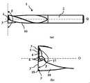
- FIG. 1 is a side view
- FIG. 1 is a partially expanded side view
- FIG. 4 is an enlarged view of the vicinity of a heel side wall surface in the drill of FIG. 3.
- the drill 1 in FIG. 1-5 is a solid type drill, and at least the portion including the cutting edge 3 is made of a hard material such as cemented carbide, cermet, cBN, etc., and has a diameter around the rotation center axis O of the drill 1.
- a drill body 2 having a substantially cylindrical shape D is provided.
- the drill 1 includes a drill body 2 having a rotation center axis O, two cutting blades 3 provided on the distal end side of the drill body 2, and behind the two cutting blades 3 and A chip discharge groove 10 provided in the rotation direction of the drill 1 from each cutting edge 3 and a heel 4 provided at a position opposite to the cutting edge 3 in contact with the chip discharge groove 10 are provided.
- the cutting edge 3 is provided from the vicinity of the center O1 of the drill 1 to the outer peripheral end of a circle having a diameter D, and continues to the side surface of the drill body 2. That is, the drill body 2 includes two cutting blades 3, two chip discharge grooves 10, two heels 4, and two first gashes 6. Further, the heel end 13 of the heel 4 opposite to the cutting edge 3 is provided at a position on the opposite bank of the cutting edge 3 in contact with the chip discharge groove 10.
- a front flank 5 is provided in the reverse rotation direction of the cutting blade 3 in the front view as viewed from the front end in FIG. Further, according to FIG. 1, at the tip of the drill 1, reverse rotation from the heel end 13 on the opposite side to the cutting edge 3 of the heel 4 to the rear end (the rear end side of the drill 1) to the first gash end point 17.
- a first gash 6 is provided in the direction.
- the cutting blade 3 -the tip flank 5 -the heel 4 -the first gash 6 -the chip discharge groove 10 are arranged in the reverse rotation direction. The first gash 6 reduces the contact resistance at the rotation central axis O at the tip of the drill 1 and the central portion in the vicinity thereof.
- the chip discharge groove 10 is provided on the outer periphery of the drill body 2 in a spiral shape over a predetermined length from the tip of the drill body 2.
- the intersecting ridge line between the chip discharge groove 10 and the tip flank 5 is the cutting edge 3.
- the rotation center axis O is indicated by a one-dot chain line.
- the drill tip angle ⁇ is 170 to 190 °. That is, when the drill tip angle ⁇ is smaller than 170 °, the bottom surface of the groove to be machined has a convex shape with a large central bulge, and when drilling with a drill for deep hole machining, Machining is performed with the drill tilted to form a tilted hole. Even when the drill tip angle ⁇ exceeds 190 °, the processed bottom surface has a concave shape with a large central recess. And since the thickness of the outer peripheral side edge part of the cutting blade 3 of the drill 1 becomes thin, the intensity
- the drill tip angle ⁇ is defined as an angle formed by the two cutting blades 3 and 3 in a side view.
- the core thickness d ⁇ ⁇ is 0.10 to 0.25 times the diameter D of the drill 1 in the cross section perpendicular to the rotation center axis O at the position having the chip discharge groove 10 shown in FIG. If the core thickness d is less than 0.10 times the diameter D of the drill 1, the strength of the drill 1 is reduced and the drill 1 is broken. When the core thickness d is larger than 0.25 times the diameter D of the drill 1, the chip discharge groove 10 becomes small and chips are easily clogged.
- the core thickness d is defined by the diameter of the largest circle c drawn at the center of the drill 1 and is equal to the distance between the groove bottoms 11 of the two chip discharge grooves 10 as shown in FIG. Note that the groove bottoms 11 and 14 are provided in each of the two chip discharge grooves 10. Further, according to this embodiment, the groove bottom 11 is included in the first gash 6.
- a more preferable range of the core thickness d with respect to the diameter D is 0.13 to 0.25 times, and more preferably 0.15 to 0.20 times.
- Two first gash 6 are provided point-symmetrically with respect to the center O1.
- a central ridge portion 8 sandwiched between two first gouaches 6 and 6 is provided in a portion including the center O1.
- the central ridge 8 has a central ridge tip angle ⁇ of 170 to 190 ° from both sides of the central ridge 8 toward the center O1 when viewed from the side, and the central ridge with respect to the diameter (D) of the drill 1
- the ratio (L / D) of the length (L) of the portion 8 is 0.15 to 0.25. Due to the presence of the central ridge portion 8 having this configuration, chip dischargeability is good, and defects in the central ridge portion 8 can be suppressed.
- the diameter D of the drill 1 indicates the distance between the outer peripheral ends of the two cutting blades 3, 3, and when a hole is drilled with the drill 1 with the diameter D, a hole with the diameter D can be formed.
- the center ridge tip angle ⁇ indicates an angle formed by ridge lines on both sides of the rotation center axis O with respect to the end ridge line on the tip side when the center ridge portion 8 is viewed from the side.
- the length (L) of the central ridge 8 extends each of the two first gash ridge lines 9 that are the intersection ridge lines of the first gash 6 and the heel 4 so as to extend the two first gashes at the center O1. The length between ridgelines 9 is indicated.
- the ratio (W / L) of the width (W) of the central ridge 8 to the length (L) of the central ridge 8 is 0.15 to 0.40.
- the width (W) of the central ridge 8 indicates the width at the center O1 of the central ridge 8.
- the distance (a) from the cutting edge 3 to the end of the first gash 6 is 0.3 to 0.5 as a ratio (a / D) to the diameter (D) of the drill.
- the first gash 6 functions to enlarge the chip discharge groove 10 in the vicinity of the cutting blade 3 and to suppress clogging of the chip whose traveling direction is not determined immediately after it is generated into the chip discharge groove 10.
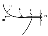
- the opening angle ⁇ of the chip discharge groove 10 is 85 to 110 °.
- the opening angle ⁇ is smaller than 85 °, the chip discharge groove 10 becomes small and chips are easily clogged. If the opening angle ⁇ is greater than 110 °, the chips are not curled by the chip discharge grooves 10 and jump out of the chip discharge grooves 10, and the chips collide with the processing surface to roughen the processing surface.
- the opening angle ⁇ of the chip discharge groove 10 is a straight line L1 (shown by a broken line) connecting the outer peripheral end P of the chip discharge groove 10 on the cutting blade 3 side and the rotation center axis O in FIG. 10 is defined by an angle formed by a straight line L2 (shown by a broken line) connecting the outer peripheral end Q on the heel 4 side and the rotation center axis O.
- the drill 1 has a groove bottom from a cutting blade side wall surface 14 located on the cutting blade 3 side of the chip discharging groove 10 in a cross section orthogonal to the rotation center axis O at the position having the chip discharging groove in FIG. 11, and a curve with a gradually decreasing radius of curvature toward the heel side wall surface 15 located on the heel 4 side.
- the chips are not easily curled or divided, but the chips are smoothly fed back along the curved surface of the chip discharge groove 10 while being appropriately curled. Therefore, even when the discharge amount increases, the chips are not collected in the chip discharge groove 10 and good chip discharge performance can be maintained.
- the radius of curvature at the outer peripheral end P of the side wall surface 14 of the cutting edge is 1.10 to 1.60 times the diameter D of the drill 1
- the radius of curvature at the groove bottom 11 is the drill.
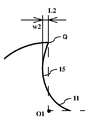
- the radius of curvature at the outer peripheral end Q of the heel side wall surface 15 is 0.45 to 0.55 times the diameter D of the drill 1.
- the groove bottom 11 is defined as an intersection of a circle c having a diameter d used for specifying the core thickness d and the drill 1.
- the point P side from the groove bottom 11 is defined as the cutting edge side wall surface 14, and the point Q side from the groove bottom 11 is defined as the heel side wall surface 15.
- the curve of the cutting blade side wall surface 14 and the curve of the heel side wall surface 15 in the sectional view of FIG. Divide equally and measure and compare the radii of curvature at each of the 8 locations. Further, the radius of curvature at the groove bottom 11 is determined in a range including two positions adjacent to the groove bottom 11 among the eight positions.
- the cutting blade side wall surface 14 is recessed in the reverse rotation direction with respect to the straight line L1 connecting the outer peripheral end P of the cutting blade side wall surface 14 and the rotation center axis O.
- the maximum middle dent amount w1 of the side wall surface 14 of the cutting edge is 0.01 to 0.04 times the diameter D of the drill.
- the cutting edge 3 extending to the side wall surface 14 of the cutting edge also has a concave shape, scooping the cutting edge 3 and improving the sharpness of the cutting edge 3.
- the cutting blade 3 when viewed from the front end side, has a concave shape in the reverse rotation direction of the drill 1, and the height (H) of the concave portion of the cutting blade 3 is the width of the central ridge portion 8.
- W It consists of the following sizes. That is, the cutting blade 3 side of the heel 4 is recessed in a concave shape, and the amount of depression (H) on the cutting blade 3 side of the heel 4 corresponding to the height (H) of the recess of the cutting blade 3 is the width of the central ridge portion 8.
- W It consists of the following sizes.
- the height of the convex portion formed on the processed surface cut by the drill 1 can be reduced, and the processed surface of the scissor drill 1 becomes more flat.
- the height (H) of the concave portion of the cutting blade 3 is reflected on the height of the convex portion formed on the processed surface cut by the drill 1.
- a desirable range of H / W is 0.51 to 0.70.
- the heel side wall surface 15 is recessed in the rotation direction with respect to a straight line L2 connecting the outer peripheral end Q of the heel side wall surface 15 and the rotation center axis O.
- the maximum middle dent amount w2 is 0.05 to 0.10 times the diameter D of the drill 1. Accordingly, the chips can be discharged backward while curling the chips into a desired shape without hindering the flow of the chips.
- a second gash 18 is provided at the outer peripheral end of the cutting blade 3, that is, at a corner portion between the tip surface and the outer peripheral surface of the cutting blade 3. Thereby, the loss of the corner portion can be suppressed.
- the chip discharge performance is particularly good. It is valid.
- a drill having the shape shown in Table 1 was prepared, which was made of a cemented carbide alloy drill body and coated with a (TiAl) N hard layer.
- the radius of curvature from the side wall surface of the cutting edge to the side wall surface of the heel is obtained by dividing the curve of the side wall surface 14 of the cutting edge and the curve of the heel side wall surface 15 into four equal parts, respectively. It was measured.
- Table 1 only the portion including the point P (denoted as P in the table), the groove bottom, and the portion including the point Q (denoted as Q in the table) are shown, but between the portion including the point P and the groove bottom , And the radius of curvature between the groove bottom and the portion including the point Q was a numerical value between the radius of curvature of both.
- Sample No. I-1 has a concave bottom surface and a drill tip angle greater than 190 °.
- the processed bottom surface was convex, and the bottom surface could not be flat or nearly flat.
- Sample No. In I-5 the number of drilled holes was reduced due to chipping at the outer peripheral edge of the cutting edge.
- I-6 the drill broke.
- Sample No. I-22 and the opening angle of the chip discharge groove are smaller than 85 °. In I-10, the chip discharge groove was small, and the chip was clogged.
- the chips jumped out of the chip discharge groove and contacted the processed surface, and the surface roughness of the processed surface was deteriorated.
- the chips were caught on the wall surface of the chip discharge groove and the flow of the chips was bad, and the chips were clogged.
- the drill tip angle is 170 to 190 °
- the core thickness is 0.10 to 0.25 times the drill diameter
- the chip discharge groove opening angle is 85 to 110 °
- the heel from the side wall surface of the cutting blade Sample No. consisting of a curve with a gradually decreasing radius of curvature toward the side wall surface.
- I-2 to 4 7 to 9, 11, 12, 16 to 21, and 23 to 26, the shape of the machining bottom surface is flat or almost flat, the chip dischargeability and the state of the drill are good, and the number of machining holes is There were many.
- a drill having the dimensions shown in Table 3 was prepared in the shape of FIGS. 1 to 3 in which the drill body of Example 1 was coated with the hard layer of Example 1.
- the diameter of the drill was 3 mm
- the core thickness was 0.45 mm
- the drill tip angle ⁇ was 180 °
- the opening angle ⁇ of the chip discharge groove viewed from the tip was 89 degrees
- a / D was 0.4.
- the performance of the drill was evaluated by the following cutting conditions. The results are shown in Table 3.
- the shape of the bottom surface of processing was flat or uneven was less than 150 ⁇ m, the chip discharging property and the state of the drill were good, and the number of processing holes was large.
- the sample Nos. With L / D of 0.15 to 0.25 and the central edge tip angle ⁇ of 170 to 190 °.
- the chip discharging property and the state of the drill were good, chipping did not occur at the center ridge, and the number of processed holes was large.
Abstract
Description
(切削条件)
被削材 :S45C
加工径 :φ8mm
加工速度:75m/分
回転数 :3000回/分
送り :0.14mm/回転
切込深さ:12mm
切削形態:突き加工
切削環境:湿式切削
評価項目:加工底面の形状、加工穴数250穴時点での切屑排出性、加工可能な穴数、加工終了時点でのドリルの状態 A drill having the shape shown in Table 1 was prepared, which was made of a cemented carbide alloy drill body and coated with a (TiAl) N hard layer. The radius of curvature from the side wall surface of the cutting edge to the side wall surface of the heel is obtained by dividing the curve of the
(Cutting conditions)
Work material: S45C
Processing diameter: φ8mm
Machining speed: 75 m / min Rotational speed: 3000 times / min Feed: 0.14 mm / Rotation depth of cut: 12 mm
Cutting form: Butting cutting environment: Wet cutting Evaluation items: Shape of the bottom surface of the machine, chip dischargeability when the number of machined holes is 250, the number of holes that can be machined, the state of the drill at the end of machining


(切削条件)
被削材 :S45C
加工径 :φ3mm
加工速度:75m/分
回転数 :8000回/分
送り :0.065mm/回転
切込深さ:4.5mm
切削形態:突き加工
切削環境:湿式切削
評価項目:加工底面の形状、加工穴数250穴時点での切屑排出性、加工できた穴数、加工終了時点でのドリルの切刃状態 A drill having the dimensions shown in Table 3 was prepared in the shape of FIGS. 1 to 3 in which the drill body of Example 1 was coated with the hard layer of Example 1. The diameter of the drill was 3 mm, the core thickness was 0.45 mm, the drill tip angle α was 180 °, the opening angle γ of the chip discharge groove viewed from the tip was 89 degrees, and a / D was 0.4. And the performance of the drill was evaluated by the following cutting conditions. The results are shown in Table 3.
(Cutting conditions)
Work material: S45C
Processing diameter: φ3mm
Machining speed: 75 m / min Rotational speed: 8000 times / min feed: 0.065 mm / rotation depth of cut: 4.5 mm
Cutting form: Butt cutting Cutting environment: Wet cutting Evaluation items: Shape of the bottom surface of the machine, chip dischargeability when the number of machined holes is 250, the number of holes that have been machined, and the cutting edge state of the drill at the end of machining

いずれの試料においても、加工底面の形状が平面または凹凸が150μmより小さく、切屑排出性およびドリルの状態が良好で、加工穴数が多いものであった。特に、L/Dが0.15~0.25であり、かつ、中心稜部先端角βが170~190°である試料No.II-2~4、7、8、10~16では、切屑排出性およびドリルの状態が良好で、中心稜部にチッピングが発生することもなく、加工穴数が多いものであった。 As shown in Table 3,
In all the samples, the shape of the bottom surface of processing was flat or uneven was less than 150 μm, the chip discharging property and the state of the drill were good, and the number of processing holes was large. In particular, the sample Nos. With L / D of 0.15 to 0.25 and the central edge tip angle β of 170 to 190 °. In II-2 to 4, 7, 8, 10 to 16, the chip discharging property and the state of the drill were good, chipping did not occur at the center ridge, and the number of processed holes was large.
2 ドリル本体
3 切刃
4 ヒール
5 先端逃げ面
6 第1ギャッシュ
8 中心稜部
9 第1ギャッシュ稜線
10 切屑排出溝
11 溝底
13 ヒール終端
14 切刃側壁面
15 ヒール側壁面
17 第1ギャッシュ終端
18 第2ギャッシュ
O 回転中心軸
D ドリルの直径
α ドリル先端角
β 中心稜部先端角
γ 切屑排出溝の開き角
c 屑排出溝を有する位置での回転中心軸に直交する断面において、ドリルの中心部に描かれる最も大きな円
d 芯厚
P 切屑排出溝の切刃側の外周端
Q 切屑排出溝のヒール側の外周端
L1 点Pと回転中心軸Oとを結ぶ直線
L2 点Qと回転中心軸Oとを結ぶ直線
w1 切刃側壁面の最大中凹み量
w2 ヒール側壁面の最大中凹み量 DESCRIPTION OF SYMBOLS 1
17
Claims (9)
- 回転中心軸を有するドリル本体と、該ドリル本体の先端側に設けられた2つの切刃と、該2つの切刃の後方でかつ各切刃からドリルの回転方向にそれぞれ設けられた切屑排出溝と、前記各切刃からドリルの逆回転方向にそれぞれ設けられた2つのヒールとを備えたドリルであって、ドリル先端角が170~190°であり、芯厚が前記ドリルの直径に対して0.10~0.25倍であり、前記切屑排出溝の開き角が85~110°であり、前記切屑排出溝を有する位置での前記回転中心軸に直交する断面において、前記切屑排出溝のうちの前記切刃側に位置する切刃側壁面から前記ヒール側に位置するヒール側壁面に向かって次第に曲率半径が小さくなる曲線を有するドリル。 A drill body having a rotation center axis, two cutting edges provided on the tip side of the drill body, and a chip discharge groove provided behind each of the two cutting edges and in the rotation direction of the drill from each cutting edge And two heels respectively provided in the reverse rotation direction of the drill from the respective cutting blades, the drill tip angle is 170 to 190 °, and the core thickness is relative to the diameter of the drill 0.10 to 0.25 times, the opening angle of the chip discharge groove is 85 to 110 °, and the cross section of the chip discharge groove is perpendicular to the rotation center axis at the position having the chip discharge groove. The drill which has a curve from which the curvature radius becomes small gradually toward the heel side wall surface located in the said heel side from the cutting blade side wall surface located in the said cutting blade side.
- 前記切刃側壁面は、該切刃側壁面の外周端と前記回転中心軸とを結ぶ直線に対して逆回転方向に中凹みしており、前記切刃側壁面の最大中凹み量が前記ドリルの直径に対して
0.01~0.04倍であり、前記ヒール側壁面は、該ヒール側壁面の外周端と前記回転中心軸とを結ぶ直線に対して回転方向に中凹みしており、前記ヒール側壁面の最大中凹み量が前記ドリルの直径に対して0.05~0.10倍である請求項1に記載のドリル。 The cutting blade side wall surface is recessed in the reverse rotation direction with respect to a straight line connecting the outer peripheral end of the cutting blade side wall surface and the rotation center axis, and the maximum middle dent amount of the cutting blade side wall surface is the drill. 0.01 to 0.04 times the diameter of the heel side wall surface, and the heel side wall surface is recessed in the rotational direction with respect to a straight line connecting the outer peripheral end of the heel side wall surface and the rotation center axis. The drill according to claim 1, wherein a maximum amount of center recess on the side surface of the heel is 0.05 to 0.10 times the diameter of the drill. - 前記切屑排出溝の溝底における曲率半径が前記ドリルの直径に対して0.56~0.9倍である請求項1または2に記載のドリル。 The drill according to claim 1 or 2, wherein the radius of curvature at the groove bottom of the chip discharge groove is 0.56 to 0.9 times the diameter of the drill.
- 前記2つのヒールの前記逆回転方向の端部にそれぞれ第1ギャッシュが設けられ、先端側から見た前記回転中心軸を中心とする円において、2つの前記第1ギャッシュ同士で挟まれた中心稜部が前記中心を含めて存在するとともに、ドリルの直径(D)に対する前記中心稜部の長さ(L)の比(L/D)が0.15~0.25であり、かつ、側方から見たとき、前記中心稜部の前記中心に向かう中心稜部先端角が170~190°である請求項1乃至3のいずれか記載のドリル。 A first ridge is provided at each end of the two heels in the reverse rotation direction, and a central ridge sandwiched between the two first gushes in a circle centered on the rotation center axis viewed from the tip side. And the ratio (L / D) of the length (L) of the central ridge to the diameter (D) of the drill is 0.15 to 0.25, and the side The drill according to any one of claims 1 to 3, wherein a tip angle of a central ridge portion toward the center of the central ridge portion is 170 to 190 ° when viewed from above.
- 前記中心稜部の長さ(L)に対する前記中心稜部の幅(W)の比(W/L)が0.15~0.40である請求項4記載のドリル。 The drill according to claim 4, wherein the ratio (W / L) of the width (W) of the central ridge to the length (L) of the central ridge is 0.15 to 0.40.
- 先端側から見たとき、切刃はドリルの逆回転方向に凹部を有しており、前記切刃の凹部の高さ(H)が前記中心稜部の幅(W)以下の大きさからなる請求項5記載のドリル。 When viewed from the front end side, the cutting edge has a recess in the reverse rotation direction of the drill, and the height (H) of the recess of the cutting edge is less than the width (W) of the central ridge. The drill according to claim 5.
- 前記ドリルの直径(D)が3mm以下である請求項1乃至6のいずれか記載のドリル。 The drill according to any one of claims 1 to 6, wherein a diameter (D) of the drill is 3 mm or less.
- 前記切刃における外周側に、第2ギャッシュが設けられている請求項1乃至7のいずれか記載のドリル。 The drill according to any one of claims 1 to 7, wherein a second gash is provided on an outer peripheral side of the cutting blade.
- 前記切刃から前記第1ギャッシュの終端までの距離(a)が、前記ドリルの直径(D)に対する比(a/D)で0.3~0.5である請求項1乃至8のいずれか記載のドリル。 The distance (a) from the cutting edge to the end of the first gash is 0.3 to 0.5 in a ratio (a / D) to the diameter (D) of the drill. The drill described.
Priority Applications (4)
| Application Number | Priority Date | Filing Date | Title |
|---|---|---|---|
| US14/900,026 US10213844B2 (en) | 2013-06-26 | 2014-06-18 | Drill |
| CN201480034365.4A CN105307807B (en) | 2013-06-26 | 2014-06-18 | drill bit |
| JP2015524000A JP6174700B2 (en) | 2013-06-26 | 2014-06-18 | drill |
| EP14818126.6A EP3015203B1 (en) | 2013-06-26 | 2014-06-18 | Drill |
Applications Claiming Priority (4)
| Application Number | Priority Date | Filing Date | Title |
|---|---|---|---|
| JP2013133913 | 2013-06-26 | ||
| JP2013-133913 | 2013-06-26 | ||
| JP2013-172395 | 2013-08-22 | ||
| JP2013172395 | 2013-08-22 |
Publications (1)
| Publication Number | Publication Date |
|---|---|
| WO2014208421A1 true WO2014208421A1 (en) | 2014-12-31 |
Family
ID=52141761
Family Applications (1)
| Application Number | Title | Priority Date | Filing Date |
|---|---|---|---|
| PCT/JP2014/066171 WO2014208421A1 (en) | 2013-06-26 | 2014-06-18 | Drill |
Country Status (5)
| Country | Link |
|---|---|
| US (1) | US10213844B2 (en) |
| EP (1) | EP3015203B1 (en) |
| JP (1) | JP6174700B2 (en) |
| CN (1) | CN105307807B (en) |
| WO (1) | WO2014208421A1 (en) |
Cited By (3)
| Publication number | Priority date | Publication date | Assignee | Title |
|---|---|---|---|---|
| JP2017193006A (en) * | 2016-04-19 | 2017-10-26 | ユニオンツール株式会社 | Boring tool |
| CN109262025A (en) * | 2018-10-29 | 2019-01-25 | 株洲钻石切削刀具股份有限公司 | A kind of drilling tool |
| JPWO2021038841A1 (en) * | 2019-08-30 | 2021-09-13 | オーエスジー株式会社 | Drill |
Families Citing this family (6)
| Publication number | Priority date | Publication date | Assignee | Title |
|---|---|---|---|---|
| JP5927671B2 (en) * | 2012-10-25 | 2016-06-01 | 住友電工ハードメタル株式会社 | Small diameter drill |
| CN107327276A (en) * | 2017-09-11 | 2017-11-07 | 张家港钻通设备有限公司 | A kind of diamond bit of use time length |
| JP7263872B2 (en) * | 2019-03-25 | 2023-04-25 | 株式会社デンソー | Drill manufacturing method |
| CN110076375A (en) * | 2019-05-05 | 2019-08-02 | 厦门金鹭特种合金有限公司 | A kind of monoblock type fluted drill |
| CN113993644B (en) * | 2019-07-08 | 2024-02-27 | 三菱综合材料株式会社 | Drill bit |
| CN112355333B (en) * | 2020-10-20 | 2023-08-08 | 科益展智能装备有限公司 | Cutter and cutter head structure thereof |
Citations (5)
| Publication number | Priority date | Publication date | Assignee | Title |
|---|---|---|---|---|
| JPS61191811U (en) * | 1985-05-20 | 1986-11-29 | ||
| JPH07308815A (en) * | 1994-05-13 | 1995-11-28 | Mitsubishi Materials Corp | Drill |
| JP2001341016A (en) * | 2000-03-31 | 2001-12-11 | Hitachi Tool Engineering Ltd | Twist drill for cutting stainless steel |
| JP2009056534A (en) | 2007-08-31 | 2009-03-19 | Nachi Fujikoshi Corp | Drill for spot facing |
| JP2012030306A (en) | 2010-07-29 | 2012-02-16 | Hitachi Tool Engineering Ltd | Drill and drilling method using the same |
Family Cites Families (6)
| Publication number | Priority date | Publication date | Assignee | Title |
|---|---|---|---|---|
| EP0320881B2 (en) * | 1987-12-14 | 2003-10-22 | Mitsubishi Materials Corporation | Twist drill |
| JPH11197926A (en) | 1998-01-12 | 1999-07-27 | Mitsubishi Materials Corp | Drill with oil hole |
| DE112006003998T5 (en) * | 2006-10-23 | 2009-06-10 | Osg Corporation, Toyokawa | drill |
| JP4894054B2 (en) * | 2007-10-26 | 2012-03-07 | 住友電工ハードメタル株式会社 | Twist drill |
| US20080138164A1 (en) * | 2008-02-18 | 2008-06-12 | Ching-Ching Chen | Drilling pin for machining metal substrates |
| JP5927671B2 (en) * | 2012-10-25 | 2016-06-01 | 住友電工ハードメタル株式会社 | Small diameter drill |
-
2014
- 2014-06-18 US US14/900,026 patent/US10213844B2/en active Active
- 2014-06-18 WO PCT/JP2014/066171 patent/WO2014208421A1/en active Application Filing
- 2014-06-18 JP JP2015524000A patent/JP6174700B2/en active Active
- 2014-06-18 EP EP14818126.6A patent/EP3015203B1/en active Active
- 2014-06-18 CN CN201480034365.4A patent/CN105307807B/en active Active
Patent Citations (5)
| Publication number | Priority date | Publication date | Assignee | Title |
|---|---|---|---|---|
| JPS61191811U (en) * | 1985-05-20 | 1986-11-29 | ||
| JPH07308815A (en) * | 1994-05-13 | 1995-11-28 | Mitsubishi Materials Corp | Drill |
| JP2001341016A (en) * | 2000-03-31 | 2001-12-11 | Hitachi Tool Engineering Ltd | Twist drill for cutting stainless steel |
| JP2009056534A (en) | 2007-08-31 | 2009-03-19 | Nachi Fujikoshi Corp | Drill for spot facing |
| JP2012030306A (en) | 2010-07-29 | 2012-02-16 | Hitachi Tool Engineering Ltd | Drill and drilling method using the same |
Cited By (6)
| Publication number | Priority date | Publication date | Assignee | Title |
|---|---|---|---|---|
| JP2017193006A (en) * | 2016-04-19 | 2017-10-26 | ユニオンツール株式会社 | Boring tool |
| CN109262025A (en) * | 2018-10-29 | 2019-01-25 | 株洲钻石切削刀具股份有限公司 | A kind of drilling tool |
| CN109262025B (en) * | 2018-10-29 | 2020-05-15 | 株洲钻石切削刀具股份有限公司 | Drilling tool |
| JPWO2021038841A1 (en) * | 2019-08-30 | 2021-09-13 | オーエスジー株式会社 | Drill |
| JP7001844B2 (en) | 2019-08-30 | 2022-01-20 | オーエスジー株式会社 | Drill |
| US11865626B2 (en) | 2019-08-30 | 2024-01-09 | Osg Corporation | Drill |
Also Published As
| Publication number | Publication date |
|---|---|
| EP3015203B1 (en) | 2020-09-09 |
| JP6174700B2 (en) | 2017-08-02 |
| JPWO2014208421A1 (en) | 2017-02-23 |
| CN105307807A (en) | 2016-02-03 |
| CN105307807B (en) | 2017-11-10 |
| US10213844B2 (en) | 2019-02-26 |
| EP3015203A1 (en) | 2016-05-04 |
| US20160144436A1 (en) | 2016-05-26 |
| EP3015203A4 (en) | 2017-02-22 |
Similar Documents
| Publication | Publication Date | Title |
|---|---|---|
| JP6174700B2 (en) | drill | |
| JP6165165B2 (en) | Indexable cutting insert, cutting tool therefor and clamping method therefor | |
| JP6611260B2 (en) | drill | |
| KR101983487B1 (en) | Drill | |
| JP6412022B2 (en) | End mill and method of manufacturing cut product | |
| JP5927671B2 (en) | Small diameter drill | |
| JP6252717B1 (en) | Small diameter drill | |
| WO2014069453A1 (en) | Ball end mill | |
| WO2016056266A1 (en) | Radius end mill | |
| JP7063403B2 (en) | Small diameter drill | |
| JP6556229B2 (en) | Drill and cutting method | |
| US10220451B2 (en) | End mill and method for manufacturing machined product | |
| JP2010158762A (en) | Method for cutting groove for turbine blade connection, and christmas cutter used for the same | |
| JP2007175830A (en) | Christmas tree formed milling cutter | |
| WO2016063894A1 (en) | End mill | |
| JP2007083381A (en) | Throw away insert and rotary cutting tool having the same | |
| JP5549080B2 (en) | drill | |
| JP2015062978A (en) | Ball end mill | |
| JP2006015418A (en) | End mill for longitudinal feed machining | |
| JP5849817B2 (en) | Square end mill | |
| JP6941047B2 (en) | Manufacturing method for rotary tools and cuttings | |
| KR20200096983A (en) | drill | |
| JP2010162643A (en) | Drill and grinding method of the drill | |
| JP5126205B2 (en) | Ball end mill | |
| WO2020240892A1 (en) | Cutting tool |
Legal Events
| Date | Code | Title | Description |
|---|---|---|---|
| WWE | Wipo information: entry into national phase |
Ref document number: 201480034365.4 Country of ref document: CN |
|
| 121 | Ep: the epo has been informed by wipo that ep was designated in this application |
Ref document number: 14818126 Country of ref document: EP Kind code of ref document: A1 |
|
| ENP | Entry into the national phase |
Ref document number: 2015524000 Country of ref document: JP Kind code of ref document: A |
|
| WWE | Wipo information: entry into national phase |
Ref document number: 2014818126 Country of ref document: EP |
|
| WWE | Wipo information: entry into national phase |
Ref document number: 14900026 Country of ref document: US |
|
| NENP | Non-entry into the national phase |
Ref country code: DE |