WO2014208292A1 - 電力安定化システムおよび制御装置 - Google Patents
電力安定化システムおよび制御装置 Download PDFInfo
- Publication number
- WO2014208292A1 WO2014208292A1 PCT/JP2014/064737 JP2014064737W WO2014208292A1 WO 2014208292 A1 WO2014208292 A1 WO 2014208292A1 JP 2014064737 W JP2014064737 W JP 2014064737W WO 2014208292 A1 WO2014208292 A1 WO 2014208292A1
- Authority
- WO
- WIPO (PCT)
- Prior art keywords
- power
- frequency
- compensation amount
- power flow
- value
- Prior art date
- Legal status (The legal status is an assumption and is not a legal conclusion. Google has not performed a legal analysis and makes no representation as to the accuracy of the status listed.)
- Ceased
Links
Images







Classifications
-
- H—ELECTRICITY
- H02—GENERATION; CONVERSION OR DISTRIBUTION OF ELECTRIC POWER
- H02J—ELECTRIC POWER NETWORKS; CIRCUIT ARRANGEMENTS OR SYSTEMS FOR SUPPLYING OR DISTRIBUTING ELECTRIC POWER; SYSTEMS FOR STORING ELECTRIC ENERGY
- H02J3/00—Circuit arrangements for AC mains or AC distribution networks
- H02J3/28—Arrangements for balancing of the load in networks by storage of energy
- H02J3/32—Arrangements for balancing of the load in networks by storage of energy using batteries or super capacitors with converting means
-
- H—ELECTRICITY
- H02—GENERATION; CONVERSION OR DISTRIBUTION OF ELECTRIC POWER
- H02J—ELECTRIC POWER NETWORKS; CIRCUIT ARRANGEMENTS OR SYSTEMS FOR SUPPLYING OR DISTRIBUTING ELECTRIC POWER; SYSTEMS FOR STORING ELECTRIC ENERGY
- H02J3/00—Circuit arrangements for AC mains or AC distribution networks
- H02J3/38—Arrangements for feeding a single network from two or more generators or sources in parallel; Arrangements for feeding already energised networks from additional generators or sources in parallel
- H02J3/381—Dispersed generators
-
- H—ELECTRICITY
- H02—GENERATION; CONVERSION OR DISTRIBUTION OF ELECTRIC POWER
- H02J—ELECTRIC POWER NETWORKS; CIRCUIT ARRANGEMENTS OR SYSTEMS FOR SUPPLYING OR DISTRIBUTING ELECTRIC POWER; SYSTEMS FOR STORING ELECTRIC ENERGY
- H02J3/00—Circuit arrangements for AC mains or AC distribution networks
- H02J3/38—Arrangements for feeding a single network from two or more generators or sources in parallel; Arrangements for feeding already energised networks from additional generators or sources in parallel
- H02J3/46—Controlling the sharing of generated power between the generators, sources or networks
- H02J3/48—Controlling the sharing of active power
-
- H—ELECTRICITY
- H02—GENERATION; CONVERSION OR DISTRIBUTION OF ELECTRIC POWER
- H02J—ELECTRIC POWER NETWORKS; CIRCUIT ARRANGEMENTS OR SYSTEMS FOR SUPPLYING OR DISTRIBUTING ELECTRIC POWER; SYSTEMS FOR STORING ELECTRIC ENERGY
- H02J2101/00—Supply or distribution of decentralised, dispersed or local electric power generation
- H02J2101/10—Dispersed power generation using fossil fuels, e.g. diesel generators
-
- H—ELECTRICITY
- H02—GENERATION; CONVERSION OR DISTRIBUTION OF ELECTRIC POWER
- H02J—ELECTRIC POWER NETWORKS; CIRCUIT ARRANGEMENTS OR SYSTEMS FOR SUPPLYING OR DISTRIBUTING ELECTRIC POWER; SYSTEMS FOR STORING ELECTRIC ENERGY
- H02J2101/00—Supply or distribution of decentralised, dispersed or local electric power generation
- H02J2101/20—Dispersed power generation using renewable energy sources
- H02J2101/22—Solar energy
- H02J2101/24—Photovoltaics
-
- H—ELECTRICITY
- H02—GENERATION; CONVERSION OR DISTRIBUTION OF ELECTRIC POWER
- H02J—ELECTRIC POWER NETWORKS; CIRCUIT ARRANGEMENTS OR SYSTEMS FOR SUPPLYING OR DISTRIBUTING ELECTRIC POWER; SYSTEMS FOR STORING ELECTRIC ENERGY
- H02J2101/00—Supply or distribution of decentralised, dispersed or local electric power generation
- H02J2101/20—Dispersed power generation using renewable energy sources
- H02J2101/28—Wind energy
-
- H—ELECTRICITY
- H02—GENERATION; CONVERSION OR DISTRIBUTION OF ELECTRIC POWER
- H02J—ELECTRIC POWER NETWORKS; CIRCUIT ARRANGEMENTS OR SYSTEMS FOR SUPPLYING OR DISTRIBUTING ELECTRIC POWER; SYSTEMS FOR STORING ELECTRIC ENERGY
- H02J2101/00—Supply or distribution of decentralised, dispersed or local electric power generation
- H02J2101/40—Hybrid power plants, i.e. a plurality of different generation technologies being operated at one power plant
-
- Y—GENERAL TAGGING OF NEW TECHNOLOGICAL DEVELOPMENTS; GENERAL TAGGING OF CROSS-SECTIONAL TECHNOLOGIES SPANNING OVER SEVERAL SECTIONS OF THE IPC; TECHNICAL SUBJECTS COVERED BY FORMER USPC CROSS-REFERENCE ART COLLECTIONS [XRACs] AND DIGESTS
- Y02—TECHNOLOGIES OR APPLICATIONS FOR MITIGATION OR ADAPTATION AGAINST CLIMATE CHANGE
- Y02E—REDUCTION OF GREENHOUSE GAS [GHG] EMISSIONS, RELATED TO ENERGY GENERATION, TRANSMISSION OR DISTRIBUTION
- Y02E10/00—Energy generation through renewable energy sources
- Y02E10/50—Photovoltaic [PV] energy
- Y02E10/56—Power conversion systems, e.g. maximum power point trackers
Definitions
- the present invention relates to a power stabilization system and a control device.
- the frequency fluctuation can be suppressed by increasing the frequency adjustment capacity by governor-free control by adding a rotating machine.
- the power generation efficiency is reduced by the amount of operation of the generator at an output lower than the rated output for frequency adjustment by the governor-free control.
- the reduction effect of carbon dioxide emissions due to the introduction of natural energy is offset by that amount.
- Patent Document 1 discloses a control device that compensates for fluctuations in power generation output by absorbing or discharging power using a power storage system such as a secondary battery.
- a power storage system such as a secondary battery.
- a distributed power source such as a wind power generator or a solar cell
- the power generation output of a distributed power source increases, it can be connected to the power grid by reducing the power released by the power storage system or increasing the power absorption. Frequency fluctuations at the system point can be suppressed.
- the power generation output of the distributed power supply decreases, the frequency fluctuation at the connection point to the power system is suppressed by decreasing the absorption of power by the power storage system or increasing the discharge of power. Can do.
- the output power of the wind power generator is detected using a current sensor and a voltage sensor, and a compensation amount is obtained according to the fluctuation.
- the system frequency may deviate from the target range.
- the system frequency may hardly change depending on the output fluctuation of the distributed power supply at another location.
- the compensation amount is obtained according to the fluctuation of the power flow detected by the control device, actually unnecessary compensation is performed, and the system frequency may deviate from the target range.
- the main present invention that solves the above-described problems is a power stabilization system that suppresses fluctuations in the active power of an AC power system, and stores power and absorbs or releases power with the AC power system.
- a storage device a power converter that mutually converts power absorbed or released between the AC power system and the power storage device; and the power converter is controlled in accordance with an active power fluctuation of the AC power system
- a control device that detects a system frequency of the AC power system as a frequency measurement value, and a power flow detection that detects a power flow of the AC power system as a power flow measurement value.
- a frequency control unit that obtains, as a frequency compensation amount, an amount of power that compensates for fluctuations in the system frequency based on the frequency measurement value, the power flow measurement value and the frequency compensation
- a power flow control unit for obtaining a power flow compensation amount as a power flow compensation amount based on a power amount, and a power conversion for controlling the power converter according to the frequency compensation amount and the power flow compensation amount
- a power control system
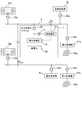
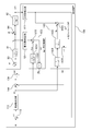
- FIGS. 1 to 3 a configuration of a power stabilization system including a control device in first to third embodiments to be described later will be described.
- the power line is indicated by a solid line and the signal line is indicated by a broken line.
- the power stabilization system 1 shown in FIG. 1 is a system for suppressing the active power fluctuation of the AC power system 9, especially the fluctuation of the system frequency.
- the AC power system 9 as a distributed power source using natural energy, for example, a solar cell module 50 installed in the solar power plant 5 and a wind power generator 60 installed in the wind power plant 6 are respectively power converters. Interconnected via 51 and 61.
- a generator (not shown) of another power plant 7 is also connected to the AC power system 9.
- the other power plants 7 may include thermal power plants, nuclear power plants, hydroelectric power plants and the like that are not accompanied by output fluctuations due to natural conditions such as wind speed and weather.
- a consumer load 8 is connected to the AC power system 9.
- the power stabilization system 1 includes a control device 10, an instrument transformer 15, a power storage device 20, and a power converter 21.
- the power storage device 20 is linked to the AC power system 9 via the power converter 21.
- the power storage device 20 has the capability of storing power and absorbing or discharging power with the AC power system 9 regardless of the type, such as a flywheel generator motor or a secondary battery. Just do it.
- the power converter 21 has a function of mutually converting power absorbed / released between the AC power system 9 and the power storage device 20.
- the control device 10 is connected to the AC power system 9 via an instrument transformer 15.
- system information indicating the state of the AC power system 9 is input to the control device 10.
- the control apparatus 10 suppresses the active power fluctuation
- the power converter 21 is controlled accordingly.
- FIG. 2 shows an example of specific connection states of the AC power system 9 and the power stabilization system 1.
- FIG. 2 shows solar cell modules 50a and 50b as an example of a distributed power source using natural energy.
- the solar cell module 50a is connected to the AC power system 9 via a power converter 51a and a (for power) transformer 52a
- the solar cell module 50b is connected to the AC power system via a power converter 51b and a transformer 52b.
- 9 linked As an example of other generators of the power plant 7, diesel generator groups 70a and 70b including a plurality of small-capacity diesel generators are shown.
- the diesel generator group 70a is linked to the AC power system 9 via the transformer 72a
- the diesel generator group 70b is linked to the AC power system 9 via the transformer 72b.
- the customer load 8a is connected to the AC power system 9 via the transformer 82a
- the customer load 8b is connected to the AC power system 9 via the transformer 82b.
- a storage battery is shown as an example of the power storage device 20, and the storage battery 20 is linked to the AC power system 9 through a power converter 21 and a transformer 22.
- the control device 10 detects voltage / current data of each node or Power flow data is input. Note that voltage / current data and power flow data for detecting the power flow PL2 of the node close to the solar cell module 50b, the diesel generator group 70b, and the customer load 8b are not input to the control device 10.
- FIG. 3 shows an outline of the configuration of the control device 10.
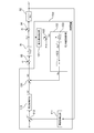
- the control device 10 shown in FIG. 3 includes a frequency detection unit 111, a frequency control unit 113, a power flow detection unit 121, a power flow control unit 123, a command value generation unit 134, and a power converter control unit 135. It is configured.
- the frequency detection unit 111 is connected to the AC power system 9 via the instrument transformer 15. And the frequency detection part 111 detects the system frequency of the alternating current power system 9 as the frequency measurement value f1 based on the voltage waveform of the alternating current power system 9 obtained by the transformer 15 for instruments. Further, the frequency controller 113 receives a frequency deviation ⁇ f between the frequency target value f0 and the frequency measurement value f1. The frequency control unit 113 outputs a frequency compensation amount Wf corresponding to the amount of power that compensates for fluctuations in the system frequency.
- System information of the AC power system 9 is input to the power flow detection unit 121.
- the power flow detection unit 121 detects the power flow of the AC power system 9 as the power flow measurement value PL1 based on the input system information. For example, voltage / current data of each node is input as system information, and a voltage value, a phase angle, active power, reactive power, and the like are obtained from these data. Note that the power flow detection unit 121 may directly input power flow data of each node.
- the power flow control unit 123 is input with the power flow measurement value PL1 or the power flow deviation ⁇ p between the power flow target value PL0 and the power flow measurement value PL1. Furthermore, the frequency compensation amount Wf is also input to the power flow control unit 123.
- the power flow control unit 123 outputs a power flow compensation amount Wp corresponding to the power amount that compensates for fluctuations in the power flow.
- the command value generator 134 receives the frequency compensation amount Wf and the power flow compensation amount Wp. Further, the control command value W 0 is input from the command value generation unit 134 to the power converter control unit 135. And from the power converter control part 135, the control signal C0 of the power converter 21 is output.
- 91 indicates a control object (plant) having the control command value W0 as the manipulated variable and the power flow PL1 as the controlled variable. If this transfer function is P1, As shown in FIG. Here, s is a Laplace transformer, and T 1 is a time constant. The control command value W0 is added with the fluctuation of the power flow PL1 as the disturbance d1 in the adder 93, and the addition result is input to the control object 91.
- reference numeral 92 denotes a control target having the power flow PL1 as an operation amount and the system frequency f1 as a control amount. If this transfer function is P2, As shown in FIG. Here, M is a unit inertia constant of the generator. The power flow PL1 is added with the fluctuation of the power flow PL2 as disturbance d2 in the adder 94, and the addition result is input to the control object 92.
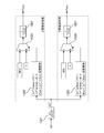
- the control device 10a shown in FIG. 4 includes a frequency detection unit 111, an adder 112, a frequency control unit 113, a power flow detection unit 121, a power flow control unit 123, and a command value generation unit 134. Yes.
- the command value generation unit 134 shown in FIG. 3 is configured as an adder, and the power converter control unit 135 is omitted.
- the power flow control unit 123 includes a power flow model unit 1231, an adder 1232, and a first proportional gain 1233.
- the value of the first proportional gain 1233 is L1.
- the power flow model unit 1231 models a change in the power flow PL1 due to the frequency compensation amount Wf, and corresponds to a nominal plant for the control target 91. Therefore, if this transfer function is P1 n , Like this, like the transfer function P1 of the control object 91, it is represented by a first-order lag element.
- the power flow model unit 1231 receives the frequency compensation amount Wf, and the power flow model unit 1231 outputs the power flow estimated value PLe.
- the command value generator (adder) 134 receives the frequency compensation amount Wf and the power flow compensation amount Wp.
- the frequency control unit 113 obtains the frequency compensation amount Wf based on the frequency deviation ⁇ f.
- the frequency control unit 113 can be configured as a PI (Proportional-Integral) controller. Further, for example, the frequency control unit 113 extracts a system frequency fluctuation component from the frequency deviation ⁇ f by a high-pass filter or the like, multiplies the extracted fluctuation component by a proportional gain, and performs phase compensation (phase advance compensation or phase delay compensation). For example, the frequency compensation amount Wf may be obtained.
- the transfer function of the frequency control unit 113 is K
- the frequency compensation amount Wf output from the frequency control unit 113 is It is expressed.
- the power flow control unit 123 obtains a power flow compensation amount Wp based on the power flow measurement value PL1 and the frequency compensation amount Wf. Specifically, first, based on the frequency compensation amount Wf, the power flow model unit 1231 estimates a change in power flow due to control of the power converter according to the frequency compensation amount Wf as the power flow estimated value PLe. Then, the power flow compensation amount Wp is obtained by multiplying the difference ⁇ p ′ between the power flow estimated value PLe and the power flow measurement value PL1 by the first proportional gain L1. Therefore, the power flow compensation amount Wp output from the power flow control unit 123 is It is expressed.
- the command value generation unit 134 adds the frequency compensation amount Wf and the power flow compensation amount Wp to obtain the control command value W0.
- the power converter control part 135 shown in FIG. 3 outputs the control signal C0 according to the control command value W0, and controls the power conversion operation
- the control device 10d shown in FIG. 5 includes a power flow control unit 153 instead of the power flow control unit 123, and further includes an adder 122 with respect to the control device 10a of the present embodiment.
- the power flow controller 153 includes a high-pass filter 1531 and a fourth proportional gain 1532.
- the value of the fourth proportional gain 1532 is L4.
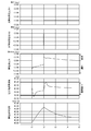
- FIG. 6 an example of the operation of suppressing the frequency fluctuation by the control device 10d shown in FIG. 5 is shown in FIG.
- FIG. 6 as an example, in the AC power system 9 shown in FIG. 2, 6% of the total capacity of the generators operating in the diesel generator groups 70a and 70b in the period from time t1 to t2. Is shown when the solar cell module 50a causes the output fluctuation (see the photovoltaic power generation output 1).
- the power converter 21 is controlled in accordance with the control command value W0 output from the control device 10d shown in FIG. 5, for example, as shown in FIG. 6, charging / discharging (absorption / release of power) by the storage battery 20 is performed.
- the frequency variation can be kept within the target range.
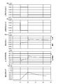
- FIG. 7 shows a case where an output fluctuation having a polarity opposite to the output fluctuation of the solar cell module 50a occurs in the solar cell module 50b (see the photovoltaic power generation output 2).
- the control device 10d output fluctuations of the solar cell modules 50a and 50b cancel each other, and the system frequency does not change.
- control device 10d calculates the power flow compensation amount Wp based on the power flow measurement value PL1 of the node close to the solar cell module 50a, and thereby charges the storage battery 20 in order to suppress the output fluctuation of the solar cell module 50a. To reduce the system frequency. Thereafter, the control device 10d obtains the frequency compensation amount Wf based on the reduced frequency measurement value f1, thereby causing the storage battery 20 to perform a discharging operation to increase the system frequency, but the system frequency temporarily falls within the target range.
- the power flow control unit 123 estimates the power flow estimated value PLe based on the frequency compensation amount Wf input from the frequency control unit 113, and the power flow estimated value PLe
- the power flow compensation amount Wp is obtained by multiplying the difference ⁇ p ′ from the power flow measurement value PL1 by the first proportional gain L1.
- the power converter 21 is controlled according to the control command value W0 obtained by adding the frequency compensation amount Wf and the power flow compensation amount Wp.
- the control device 10b shown in FIG. 9 further includes a disturbance feedback unit 143 and an adder 144 with respect to the control device 10a of the first embodiment.
- the disturbance feedback unit 143 includes system frequency model units 1431 and 1432, an adder 1433, and a second proportional gain 1434.
- the value of the second proportional gain 1434 is L2.
- System frequency model units 1431 and 1432 model changes in system frequency f1 due to frequency compensation amount Wf, and correspond to nominal plants for control objects 91 and 92, respectively. Therefore, the transfer function of the system frequency model unit 1431 is the same as the transfer function P1 n of the power flow model unit 1231, and the transfer function of the system frequency model unit 1432 is P2 n . Like the transfer function P2 of the control object 92, it is expressed by an integral element.
- the system frequency model units 1431 and 1432 are connected in series, the system frequency model unit 1431 receives the frequency compensation amount Wf, and the system frequency model unit 1432 outputs the estimated frequency value fe.
- the frequency compensation amount Wf and the frequency disturbance compensation amount Wd are input to the adder 144.
- the adder 134 receives the output value of the adder 144 and the power flow compensation amount Wp.
- the adders 134 and 144 correspond to a command value generation unit.
- the disturbance feedback unit 143 obtains the frequency disturbance compensation amount Wd based on the frequency measurement value f1 and the frequency compensation amount Wf. Specifically, first, system frequency model units 1431 and 1432 estimate, as frequency estimated value fe, a change in system frequency by control of the power converter according to frequency compensation amount Wf, based on frequency compensation amount Wf. . Then, the frequency disturbance compensation amount Wd is obtained by multiplying the difference ⁇ f ′ between the frequency estimation value fe and the frequency measurement value f1 by the second proportional gain L2. Therefore, the frequency disturbance compensation amount Wd output from the disturbance feedback unit 143 is It is expressed.
- the command value generator adds the frequency compensation amount Wf, the power flow compensation amount Wp, and the frequency disturbance compensation amount Wd to obtain the control command value W0.
- the power converter control unit 135 shown in FIG. 3 outputs a control signal C0 according to the control command value W0, and controls the power conversion operation of the power converter 21.
- the disturbance feedback unit 143 estimates the frequency estimation value fe based on the frequency compensation amount Wf input from the frequency control unit 113, and the difference between the frequency estimation value fe and the frequency measurement value f1.
- a frequency disturbance compensation amount Wd is obtained by multiplying ⁇ f ′ by the second proportional gain L2.
- the power converter 21 is controlled according to a control command value W0 obtained by adding the frequency compensation amount Wf, the power flow compensation amount Wp, and the frequency disturbance compensation amount Wd.
- the control device 10c illustrated in FIG. 10 includes a power flow control unit 133 instead of the power flow control unit 123, and includes an adder 122 and an upper and lower limit setting unit 132, as compared with the control device 10a of the first embodiment. Furthermore, it is comprised.
- the power flow control unit 133 includes a high-pass filter 1331, an adder 1332, a limiter unit 1333, and a third proportional gain 1334.
- the value of the third proportional gain 1334 is L3.
- the power flow deviation ⁇ p is input from the adder 122 to the high-pass filter 1331, and the power flow fluctuation component ⁇ p ′′ is output from the high-pass filter 1331.
- the power flow fluctuation component is output to the adder 1332.
- ⁇ p ′′ and the frequency compensation amount Wf are input.
- the difference between the power flow fluctuation component ⁇ p ′′ and the frequency compensation amount Wf is input from the adder 1332 to the limiter unit 1333.
- the output value of the limiter unit 1333 is input to the third proportional gain 1334. Is input, and the power flow compensation amount Wp is output from the third proportional gain 1334.
- FIG. 11 shows the configuration of the upper and lower limit setting unit 132 in the present embodiment.
- the upper / lower limit setting unit 132 illustrated in FIG. 11 includes a high-pass filter 1321, determination units 1322 and 1325, selection units 1323 and 1326, and first-order lag elements 1324 and 1327.
- the determination unit 1322, the selection unit 1323, and the first-order lag element 1324 correspond to an upper limit value setting unit
- the determination unit 1325, the selection unit 1326, and the first-order lag element 1327 are lower limit value setting units. It corresponds to.
- the frequency deviation ⁇ f is input to the high pass filter 1321.
- the system frequency fluctuation component ⁇ f ′′ output from the high-pass filter 1321 is input to the determination units 1322 and 1325.
- the selection units 1323 and 1326 are configured as 2-input 1-output multiplexers.
- An output value of the determination unit 1322 is input to the selection control input of the selection unit 1323, and an upper limit set value MAX is input to a data input corresponding to the case where the output value of the determination unit 1322 is 1, and the determination unit 1322 The value “0” is input to the data input corresponding to the case where the output value is 0.
- the output value of the determination unit 1325 is input to the selection control input of the selection unit 1326, and the lower limit set value MIN is input to the data input corresponding to the case where the output value of the determination unit 1325 is 1, and the determination unit The value “0” is input to the data input corresponding to the case where the output value of 1325 is 0.
- the output value of the selection unit 1323 is input to the primary delay element 1324, and the upper limit value Pmax is output from the primary delay element 1324.
- the output value of the selection unit 1326 is input to the primary delay element 1327, and the lower limit value Pmin is output from the primary delay element 1327.
- the power flow control unit 133 obtains a power flow compensation amount Wp based on the power flow deviation ⁇ p and the frequency compensation amount Wf. Specifically, the power flow control unit 133 first extracts the power flow fluctuation component ⁇ p ′′ from the power flow deviation ⁇ p by the high-pass filter 1331. Then, the extracted fluctuation component ⁇ p ′′ and the frequency compensation amount Wf are extracted. The difference ( ⁇ p ′′ ⁇ Wf) is limited by the limiter unit 1333 with the upper limit value Pmax or the lower limit value Pmin, and multiplied by the third proportional gain L3 to obtain the power flow compensation amount Wp.
- the upper / lower limit setting unit 132 extracts the fluctuation component ⁇ f ′′ of the system frequency from the frequency deviation ⁇ f by the high-pass filter 1321, and the upper limit value Pmax of the limiter unit 1333 according to the magnitude of the extracted fluctuation component ⁇ f ′′. And the lower limit value Pmin is switched.
- the third threshold value Arst 0.
- the determination unit 1322 holds the output state while Set ⁇ f ” ⁇ Arst.
- the first-order lag element 1324 changes the value“ 0 ”to the upper limit set value MAX when the upper limit value Pmax is switched. The change or the change from the upper limit set value MAX to the value “0” is moderated.
- the fourth threshold value Brst 0.
- the determination unit 1325 holds the output state while Brst ⁇ f ′′ ⁇ Bset.
- the first-order lag element 1327 changes from the value “0” to the lower limit set value MIN when the lower limit value Pmin is switched. The change or the change from the lower limit set value MIN to the value “0” is moderated.
- the power flow control unit 133 extracts the power flow fluctuation component ⁇ p ′′ from the power flow deviation ⁇ p, and the upper and lower limit setting unit 132 uses the frequency deviation ⁇ f to change the system frequency fluctuation component ⁇ f ′′. Is extracted. Only when the absolute value of the fluctuation component ⁇ f ′′ is large to some extent, output from the limiter unit 1333 is started, and the output value is multiplied by the third proportional gain L3 to obtain the power flow compensation amount Wp. Then, the power converter 21 is controlled according to the control command value W0 obtained by adding the frequency compensation amount Wf and the power flow compensation amount Wp.
- the power amount for compensating for the fluctuation of the system frequency of the AC power system 9 is set based on the frequency measurement value f1 (frequency deviation ⁇ f).
- the corresponding frequency compensation amount Wf is obtained, and based on the power flow measurement value PL1 (power flow deviation ⁇ p) and the frequency compensation amount Wf, the power flow compensation amount Wp corresponding to the power amount that compensates for fluctuations in the power flow is obtained.
- a change in the power flow due to the control of the power converter according to the frequency compensation amount Wf is estimated as the power flow estimated value PLe, and the power flow estimated value
- the power flow compensation amount Wp By calculating the power flow compensation amount Wp by multiplying the difference ⁇ p ′ between PLe and the measured power flow value PL1 by the first proportional gain L1, output fluctuations of opposite polarities canceling each other occur in a plurality of distributed power sources. Even in this case, the frequency variation can be kept within the target range.
- the change of the system frequency due to the control of the power converter according to the frequency compensation amount Wf is estimated as the frequency estimated value fe, and the frequency estimated value fe
- the frequency disturbance compensation amount Wd is further obtained by multiplying the difference ⁇ f ′ from the frequency measurement value f1 by the second proportional gain L2, thereby adding the frequency compensation amount Wf, the power flow compensation amount Wp, and the frequency disturbance compensation amount Wd.
- the control command value W0 the power conversion operation of the power converter 21 is controlled, and even when output fluctuations with opposite polarities canceling each other occur in a plurality of distributed power sources, the frequency fluctuation is within the target range. Can fit in.
- the limiter unit 1333 when the fluctuation component ⁇ f ′′ of the system frequency is extracted and ⁇ f ′′ ⁇ Aset ( ⁇ 0), the limiter unit 1333 outputs the upper limit value.
- Pmax MAX
- ⁇ f ′′ ⁇ Aset > 0
- Pmin MIN
- the output value is multiplied by the third proportional gain L3 to obtain the power flow compensation amount Wp, so that the power flow compensation amount Wp is output only when the absolute value of the fluctuation component ⁇ f ′′ is large to some extent. Therefore, unnecessary compensation control according to the fluctuation component ⁇ p ′′ of the power flow can be suppressed, and deviation of the system frequency from the target range can be prevented.
- the control constants such as the first proportional gain L1, the second proportional gain L2, and the third proportional gain L3 use a general control system design technique. Can be obtained. For example, it can be obtained experimentally by performing an actual operation test in the AC power system 9 that is a target for suppressing frequency fluctuations or an operation simulation using a model of the AC power system 9.
- the first proportional gain L1 and the second proportional gain L2 are determined first.
- the first proportional gain L1 is first determined by setting the second proportional gain L2 to 0, and then the second proportional gain L2 is determined using the determined first proportional gain L1.
- the threshold values of the first threshold value Aset, the second threshold value Bset, the third threshold value Arst, and the fourth threshold value Brst are determined based on the characteristics of the AC power system 9 and the target range of the system frequency. It can be obtained experimentally as in the case of the control constant. Similarly, the first-order lag elements 1324 and 1327 can also be obtained experimentally from the characteristics of the AC power system 9 and the like.
Landscapes
- Engineering & Computer Science (AREA)
- Power Engineering (AREA)
- Supply And Distribution Of Alternating Current (AREA)
Abstract
Description
以下、図1ないし図3を参照して、後述する第1ないし第3実施形態における制御装置を備えた電力安定化システムの構成について説明する。なお、図1ないし図3においては、電力線を実線で示し、信号線を破線で示している。
===制御装置の構成===
以下、図4を参照して、第1の実施形態における制御装置の構成について説明する。



次に、本実施形態における制御装置の動作について説明する。


以下、図5ないし図8を適宜参照して、本実施形態における制御装置による周波数変動の抑制動作の具体例について説明する。


本実施形態の制御装置10aでは、電力潮流制御部123は、周波数制御部113から入力される周波数補償量Wfに基づいて電力潮流推定値PLeを推定し、電力潮流推定値PLeと電力潮流計測値PL1との差Δp’に第1の比例ゲインL1を乗算して電力潮流補償量Wpを求めている。そして、周波数補償量Wfと電力潮流補償量Wpとを加算した制御指令値W0に応じて電力変換器21を制御する。これにより、例えば図8に示すように、太陽電池モジュール50aおよび50bにおいて互いに打ち消し合う逆極性の出力変動が生じた場合であっても、不要な補償制御を抑制し、周波数変動を目標範囲内に収めることができる。
===制御装置の構成===
以下、図9を参照して、第2の実施形態における制御装置の構成について説明する。

次に、本実施形態における制御装置の動作について説明する。

===制御装置の構成===
以下、図10および図11を参照して、第3の実施形態における制御装置の構成について説明する。
次に、本実施形態における制御装置の動作について説明する。
5 太陽光発電所
6 風力発電所
7 発電所
8(8a、8b) 需要家負荷
9 交流電力系統
10(10a~10d) 制御装置
15 計器用変圧器
20 電力貯蔵装置(蓄電池)
21、51(51a、51b)、61 電力変換器
22、52a、52b、72a、72b、82a、82b (電力用)変圧器
50(50a、50b) 太陽電池モジュール
60 風力発電機
70a、70b ディーゼル発電機群
91、92 制御対象
93、94 加算器
111 周波数検出部
112、122、144 加算器
113 周波数制御部
121 電力潮流検出部
123、133、153 電力潮流制御部
132 上下限設定部
134 指令値生成部(加算器)
135 電力変換器制御部
143 外乱フィードバック部
1231 電力潮流モデル部
1232、1332、1433 加算器
1233、1334、1434、1532 比例ゲイン
1321、1331、1531 ハイパスフィルタ
1322、1325 判定部
1323、1326 選択部
1324、1327 一次遅れ要素
1333 リミッタ部
1431、1432 系統周波数モデル部
Claims (6)
- 交流電力系統の有効電力変動を抑制する電力安定化システムであって、
電力を貯蔵し、前記交流電力系統との間で電力の吸収または放出を行う電力貯蔵装置と、
前記交流電力系統と前記電力貯蔵装置との間で吸収または放出される電力を相互に変換する電力変換器と、
前記交流電力系統の有効電力変動に応じて前記電力変換器を制御する制御装置と、
を備え、
前記制御装置は、
前記交流電力系統の系統周波数を周波数計測値として検出する周波数検出部と、
前記交流電力系統の電力潮流を電力潮流計測値として検出する電力潮流検出部と、
前記周波数計測値に基づいて、前記系統周波数の変動を補償する電力量を周波数補償量として求める周波数制御部と、
前記電力潮流計測値および前記周波数補償量に基づいて、前記電力潮流の変動を補償する電力量を電力潮流補償量として求める電力潮流制御部と、
前記周波数補償量および前記電力潮流補償量に応じて前記電力変換器を制御する電力変換器制御部と、
を有することを特徴とする電力安定化システム。 - 請求項1に記載の電力安定化システムであって、
前記電力潮流制御部は、
前記周波数補償量に応じた前記電力変換器の制御による前記電力潮流の変化を電力潮流推定値として推定する電力潮流モデル部を含み、
前記電力潮流推定値と前記電力潮流計測値との差に第1の比例ゲインを乗算して前記電力潮流補償量を求めることを特徴とする電力安定化システム。 - 請求項2に記載の電力安定化システムであって、
前記周波数補償量に応じた前記電力変換器の制御による前記系統周波数の変化を周波数推定値として推定する系統周波数モデル部を含み、前記周波数推定値と前記周波数計測値との差に第2の比例ゲインを乗算して周波数外乱補償量を求める外乱フィードバック部をさらに有し、
前記電力変換器制御部は、前記周波数補償量、前記電力潮流補償量、および前記周波数外乱補償量に応じて前記電力変換器を制御することを特徴とする電力安定化システム。 - 請求項1に記載の電力安定化システムであって、
前記電力潮流制御部は、
前記電力潮流の変動成分と前記周波数補償量との差が入力され、上限値または下限値で制限して出力するリミッタ部を含み、
前記リミッタ部の出力値に第3の比例ゲインを乗算して前記電力潮流補償量を求め、
前記リミッタ部は、
前記系統周波数の変動成分が所定の負の第1閾値以下となった場合にのみ、前記上限値で制限された出力値の出力を開始し、
前記系統周波数の変動成分が所定の正の第2閾値以上となった場合にのみ、前記下限値で制限された出力値の出力を開始することを特徴とする電力安定化システム。 - 請求項4に記載の電力安定化システムであって、
前記リミッタ部は、
前記上限値で制限された出力値を出力している場合に、前記系統周波数の変動成分が前記第1閾値より大きい所定の第3閾値以上となったときには、前記上限値で制限された出力値の出力を停止し、
前記下限値で制限された出力値を出力している場合に、前記系統周波数の変動成分が前記第2閾値より小さい所定の第4閾値以下となったときには、前記下限値で制限された出力値の出力を停止することを特徴とする電力安定化システム。 - 電力を貯蔵し、交流電力系統との間で電力の吸収または放出を行う電力貯蔵装置と、
前記交流電力系統と前記電力貯蔵装置との間で吸収または放出される電力を相互に変換する電力変換器と、
ともに用いられ、前記交流電力系統の有効電力変動を抑制すべく前記電力変換器を制御する制御装置であって、
前記交流電力系統の系統周波数を周波数計測値として検出する周波数検出部と、
前記交流電力系統の電力潮流を電力潮流計測値として検出する電力潮流検出部と、
前記周波数計測値に基づいて、前記系統周波数の変動を補償する電力量を周波数補償量として求める周波数制御部と、
前記電力潮流計測値および前記周波数補償量に基づいて、前記電力潮流の変動を補償する電力量を電力潮流補償量として求める電力潮流制御部と、
前記周波数補償量および前記電力潮流補償量に応じて前記電力変換器を制御する電力変換器制御部と、
を有することを特徴とする制御装置。
Priority Applications (2)
| Application Number | Priority Date | Filing Date | Title |
|---|---|---|---|
| JP2015523945A JP6032365B2 (ja) | 2013-06-27 | 2014-06-03 | 電力安定化システムおよび制御装置 |
| PH12015501499A PH12015501499A1 (en) | 2013-06-27 | 2015-06-30 | Power stabilization system and control device |
Applications Claiming Priority (2)
| Application Number | Priority Date | Filing Date | Title |
|---|---|---|---|
| JP2013135246 | 2013-06-27 | ||
| JP2013-135246 | 2013-06-27 |
Publications (1)
| Publication Number | Publication Date |
|---|---|
| WO2014208292A1 true WO2014208292A1 (ja) | 2014-12-31 |
Family
ID=52141640
Family Applications (1)
| Application Number | Title | Priority Date | Filing Date |
|---|---|---|---|
| PCT/JP2014/064737 Ceased WO2014208292A1 (ja) | 2013-06-27 | 2014-06-03 | 電力安定化システムおよび制御装置 |
Country Status (3)
| Country | Link |
|---|---|
| JP (1) | JP6032365B2 (ja) |
| PH (1) | PH12015501499A1 (ja) |
| WO (1) | WO2014208292A1 (ja) |
Cited By (2)
| Publication number | Priority date | Publication date | Assignee | Title |
|---|---|---|---|---|
| JP2016178736A (ja) * | 2015-03-18 | 2016-10-06 | 中国電力株式会社 | 周波数制御方法 |
| EP3739711A1 (de) * | 2019-05-13 | 2020-11-18 | TRIMET Aluminium SE | Mehrkanal-prl: verfahren und system zum erbringen einer regelleistung zum regeln einer netzfrequenz eines stromnetzes sowie stromnetz |
Citations (2)
| Publication number | Priority date | Publication date | Assignee | Title |
|---|---|---|---|---|
| JP2011050133A (ja) * | 2009-08-25 | 2011-03-10 | Toshiba Corp | 電力系統の需給制御装置、需給制御プログラム及びその記録媒体 |
| JP2011114899A (ja) * | 2009-11-25 | 2011-06-09 | Fuji Electric Systems Co Ltd | 負荷周波数制御方法及び負荷周波数制御装置 |
Family Cites Families (2)
| Publication number | Priority date | Publication date | Assignee | Title |
|---|---|---|---|---|
| JPH0965588A (ja) * | 1995-08-24 | 1997-03-07 | Hitachi Ltd | 電力貯蔵システム |
| JP5478137B2 (ja) * | 2009-07-17 | 2014-04-23 | 九州電力株式会社 | 電力安定化装置、その制御装置 |
-
2014
- 2014-06-03 WO PCT/JP2014/064737 patent/WO2014208292A1/ja not_active Ceased
- 2014-06-03 JP JP2015523945A patent/JP6032365B2/ja active Active
-
2015
- 2015-06-30 PH PH12015501499A patent/PH12015501499A1/en unknown
Patent Citations (2)
| Publication number | Priority date | Publication date | Assignee | Title |
|---|---|---|---|---|
| JP2011050133A (ja) * | 2009-08-25 | 2011-03-10 | Toshiba Corp | 電力系統の需給制御装置、需給制御プログラム及びその記録媒体 |
| JP2011114899A (ja) * | 2009-11-25 | 2011-06-09 | Fuji Electric Systems Co Ltd | 負荷周波数制御方法及び負荷周波数制御装置 |
Cited By (4)
| Publication number | Priority date | Publication date | Assignee | Title |
|---|---|---|---|---|
| JP2016178736A (ja) * | 2015-03-18 | 2016-10-06 | 中国電力株式会社 | 周波数制御方法 |
| EP3739711A1 (de) * | 2019-05-13 | 2020-11-18 | TRIMET Aluminium SE | Mehrkanal-prl: verfahren und system zum erbringen einer regelleistung zum regeln einer netzfrequenz eines stromnetzes sowie stromnetz |
| WO2020229072A1 (de) | 2019-05-13 | 2020-11-19 | Trimet Aluminium Se | Mehrkanal-prl: verfahren und system zum erbringen einer regelleistung zum regeln einer netzfrequenz eines stromnetzes sowie stromnetz |
| CN113812054A (zh) * | 2019-05-13 | 2021-12-17 | 特里梅特铝业股份公司 | 多通道fcr:提供控制电力网络的网络频率的控制电力的方法和系统以及电力网络 |
Also Published As
| Publication number | Publication date |
|---|---|
| JP6032365B2 (ja) | 2016-11-24 |
| JPWO2014208292A1 (ja) | 2017-02-23 |
| PH12015501499A1 (en) | 2015-09-28 |
Similar Documents
| Publication | Publication Date | Title |
|---|---|---|
| EP2822163A1 (en) | Power supply system | |
| JP5099237B2 (ja) | 電力安定化システム、電力安定化制御プログラム、電力安定化制御方法 | |
| JP5566736B2 (ja) | 太陽光発電システム | |
| JP5244923B2 (ja) | 風力発電装置及び出力制御方法 | |
| CN101438476B (zh) | 新的能量发电系统输出起伏缓和装置 | |
| JP6232899B2 (ja) | 電力補償装置 | |
| US9391537B2 (en) | Photovoltaic system and power supply system | |
| JPWO2019116419A1 (ja) | 電力変換装置 | |
| JP6020721B2 (ja) | 電力安定化システムおよび制御装置 | |
| KR20090042794A (ko) | 전력 저장 장치 및 하이브리드형 분산 전원 시스템 | |
| US20160149415A1 (en) | Control device and control method of microgrid | |
| JP5125274B2 (ja) | 新エネルギー発電システム出力変動緩和装置 | |
| JP4487092B2 (ja) | ターボチャージャ発電装置 | |
| CN106159980A (zh) | 发电系统和能量管理方法 | |
| JP2010071159A (ja) | 風車と蓄電池による風力発電電力平滑化装置 | |
| JP5830484B2 (ja) | 無効電力比率制御器、無効電力比率制御方法、およびこれを用いた発電システム | |
| JP5549994B2 (ja) | コンバータ制御装置 | |
| JP6032365B2 (ja) | 電力安定化システムおよび制御装置 | |
| JP5742591B2 (ja) | 太陽光発電設備 | |
| JP6380985B2 (ja) | 直流送電システム | |
| JP6726937B2 (ja) | ウィンドファーム制御装置,ウィンドファーム及びウィンドファーム制御方法 | |
| CN105706347B (zh) | 逆变器控制装置 | |
| JP2011167014A (ja) | コンバータ制御装置 | |
| KR20160050152A (ko) | 가변속 디젤발전기를 포함하는 마이크로그리드 시스템 및 그 제어 방법 | |
| WO2024184948A1 (ja) | 電力変換装置、電力変換方法、および電力変換プログラム |
Legal Events
| Date | Code | Title | Description |
|---|---|---|---|
| 121 | Ep: the epo has been informed by wipo that ep was designated in this application |
Ref document number: 14816847 Country of ref document: EP Kind code of ref document: A1 |
|
| WWE | Wipo information: entry into national phase |
Ref document number: 12015501499 Country of ref document: PH |
|
| ENP | Entry into the national phase |
Ref document number: 2015523945 Country of ref document: JP Kind code of ref document: A |
|
| WWE | Wipo information: entry into national phase |
Ref document number: IDP00201504133 Country of ref document: ID |
|
| NENP | Non-entry into the national phase |
Ref country code: DE |
|
| 122 | Ep: pct application non-entry in european phase |
Ref document number: 14816847 Country of ref document: EP Kind code of ref document: A1 |