WO2014208258A1 - 超音波診断装置、画像描出方法およびプログラム - Google Patents
超音波診断装置、画像描出方法およびプログラム Download PDFInfo
- Publication number
- WO2014208258A1 WO2014208258A1 PCT/JP2014/064176 JP2014064176W WO2014208258A1 WO 2014208258 A1 WO2014208258 A1 WO 2014208258A1 JP 2014064176 W JP2014064176 W JP 2014064176W WO 2014208258 A1 WO2014208258 A1 WO 2014208258A1
- Authority
- WO
- WIPO (PCT)
- Prior art keywords
- pixel
- ultrasonic
- reflection point
- images
- image
- Prior art date
- Legal status (The legal status is an assumption and is not a legal conclusion. Google has not performed a legal analysis and makes no representation as to the accuracy of the status listed.)
- Ceased
Links
Images








Classifications
-
- A—HUMAN NECESSITIES
- A61—MEDICAL OR VETERINARY SCIENCE; HYGIENE
- A61B—DIAGNOSIS; SURGERY; IDENTIFICATION
- A61B8/00—Diagnosis using ultrasonic, sonic or infrasonic waves
- A61B8/52—Devices using data or image processing specially adapted for diagnosis using ultrasonic, sonic or infrasonic waves
- A61B8/5207—Devices using data or image processing specially adapted for diagnosis using ultrasonic, sonic or infrasonic waves involving processing of raw data to produce diagnostic data, e.g. for generating an image
-
- A—HUMAN NECESSITIES
- A61—MEDICAL OR VETERINARY SCIENCE; HYGIENE
- A61B—DIAGNOSIS; SURGERY; IDENTIFICATION
- A61B8/00—Diagnosis using ultrasonic, sonic or infrasonic waves
- A61B8/08—Clinical applications
- A61B8/0825—Clinical applications for diagnosis of the breast, e.g. mammography
-
- A—HUMAN NECESSITIES
- A61—MEDICAL OR VETERINARY SCIENCE; HYGIENE
- A61B—DIAGNOSIS; SURGERY; IDENTIFICATION
- A61B8/00—Diagnosis using ultrasonic, sonic or infrasonic waves
- A61B8/08—Clinical applications
- A61B8/0833—Clinical applications involving detecting or locating foreign bodies or organic structures
-
- A—HUMAN NECESSITIES
- A61—MEDICAL OR VETERINARY SCIENCE; HYGIENE
- A61B—DIAGNOSIS; SURGERY; IDENTIFICATION
- A61B8/00—Diagnosis using ultrasonic, sonic or infrasonic waves
- A61B8/13—Tomography
- A61B8/14—Echo-tomography
-
- G—PHYSICS
- G01—MEASURING; TESTING
- G01S—RADIO DIRECTION-FINDING; RADIO NAVIGATION; DETERMINING DISTANCE OR VELOCITY BY USE OF RADIO WAVES; LOCATING OR PRESENCE-DETECTING BY USE OF THE REFLECTION OR RERADIATION OF RADIO WAVES; ANALOGOUS ARRANGEMENTS USING OTHER WAVES
- G01S7/00—Details of systems according to groups G01S13/00, G01S15/00, G01S17/00
- G01S7/52—Details of systems according to groups G01S13/00, G01S15/00, G01S17/00 of systems according to group G01S15/00
- G01S7/52017—Details of systems according to groups G01S13/00, G01S15/00, G01S17/00 of systems according to group G01S15/00 particularly adapted to short-range imaging
- G01S7/52023—Details of receivers
- G01S7/52036—Details of receivers using analysis of echo signal for target characterisation
-
- G—PHYSICS
- G01—MEASURING; TESTING
- G01S—RADIO DIRECTION-FINDING; RADIO NAVIGATION; DETERMINING DISTANCE OR VELOCITY BY USE OF RADIO WAVES; LOCATING OR PRESENCE-DETECTING BY USE OF THE REFLECTION OR RERADIATION OF RADIO WAVES; ANALOGOUS ARRANGEMENTS USING OTHER WAVES
- G01S7/00—Details of systems according to groups G01S13/00, G01S15/00, G01S17/00
- G01S7/52—Details of systems according to groups G01S13/00, G01S15/00, G01S17/00 of systems according to group G01S15/00
- G01S7/52017—Details of systems according to groups G01S13/00, G01S15/00, G01S17/00 of systems according to group G01S15/00 particularly adapted to short-range imaging
- G01S7/52053—Display arrangements
- G01S7/52057—Cathode ray tube displays
- G01S7/52071—Multicolour displays; using colour coding; Optimising colour or information content in displays, e.g. parametric imaging
Definitions
- the present invention relates to an ultrasonic diagnostic apparatus, an image rendering method, and a program for generating a tomographic image of a subject by transmitting and receiving ultrasonic waves.
- An ultrasonic diagnostic apparatus that transmits ultrasonic waves from an ultrasonic probe to a subject and generates a tomographic image of the subject based on a reflected wave from the inside of the subject is known.
- a technique is known in which ultrasonic waves are transmitted in a plurality of directions different from each other and one tomographic image is generated based on a reception signal obtained by each transmission.
- Patent Document 1 Japanese Patent Application Laid-Open No. 2012-213606 discloses a first scan that performs ultrasonic transmission in a direction perpendicular to the azimuth direction to a subject into which a puncture needle has been inserted, and a first scan. It is described that a second scan is performed in which ultrasonic transmission is performed in each of a plurality of directions different from the current direction.
- the first ultrasonic image is generated using the reflected wave received by the ultrasonic probe by the first scan, and the ultrasonic probe 1 is received by the second scan.
- a second ultrasonic image group that is an ultrasonic image for each of a plurality of directions is generated using the reflected wave.
- an image that matches a predetermined condition is selected as a third ultrasound image from the second ultrasound image group, a puncture needle region is extracted from the third ultrasound image, and the extracted puncture needle A needle image is generated based on the region, and a composite image of the first ultrasonic image and the needle image is generated.
- the mammography apparatus using X-rays is superior to the ultrasonic diagnostic apparatus in terms of the rendering performance for the microcalcification portion generated in the breast. This is because in the ultrasound image, both the mammary gland structure and the microcalcification portion are depicted as reflection points with relatively high brightness, and the image of the microcalcification portion is buried in the image of the mammary gland structure.
- the present invention has been made in view of the above points, and an ultrasonic diagnostic apparatus, an image rendering method, and an image rendering method capable of improving the rendering performance of a microstructure such as a microcalcification portion in a subject as compared with the conventional one. Provide a program.
- image generation for generating a plurality of images corresponding to each of the plurality of directions based on reflected waves of ultrasonic waves reflected from a reflection point in a plurality of different directions.
- an extracting means for performing comparison analysis of the pixel values of the respective pixels corresponding to the same reflection point in the plurality of images generated by the image generating means and extracting specific pixels that approximate the pixel values;
- an ultrasonic diagnostic apparatus including display means for displaying the specific pixel extracted by the extraction means.
- the extraction unit is configured to obtain a pixel value between the plurality of images among the pixels corresponding to the same reflection point in the plurality of images generated by the image generation unit.
- an ultrasonic diagnostic apparatus according to a first aspect of extracting, as the specific pixel, a pixel whose difference value or index value indicating the magnitude of variation is a predetermined threshold value or less.
- the extraction unit is configured to obtain a pixel value between the plurality of images among the pixels corresponding to the same reflection point in the plurality of images generated by the image generation unit.
- an ultrasonic diagnostic apparatus according to a first aspect that extracts a pixel having a correlation value equal to or greater than a predetermined threshold as the specific pixel.
- the extraction unit extracts, as the specific pixel, a pixel having a pixel value equal to or greater than a predetermined threshold in each of the plurality of images generated by the image generation unit.
- the extracting means is the smallest pixel between the plurality of images among the pixels corresponding to the same reflection point in the plurality of images generated by the image generating means.
- An ultrasonic diagnostic apparatus according to a first aspect for extracting pixels having a value equal to or greater than a predetermined threshold is provided.
- the ultrasonic diagnostic apparatus according to any one of the first to fifth aspects, wherein the display means displays only the pixels extracted by the extraction means.
- the display means displays the pixels extracted by the extraction means on any image generated by the image generation means so as to be visible.
- An ultrasonic diagnostic apparatus according to any aspect is provided.
- the extraction means includes a minimum pixel value between the plurality of images among the pixels corresponding to the same reflection point in the plurality of images generated by the image generation means.
- the ultrasonic diagnostic apparatus according to the first aspect of the present invention is provided, wherein the display means displays an image composed of the pixels extracted by the extraction means.
- the image generation means is based on each of a plurality of reception signals generated in response to each transmission of ultrasonic waves sequentially transmitted in a plurality of different directions.
- An ultrasonic diagnostic apparatus according to any one of the first to eighth aspects for generating a plurality of images corresponding to each of the plurality of directions is provided.
- each of the plurality of directions is subjected to phasing addition processing along each of a plurality of different directions with respect to the reception signal generated in response to transmission of the ultrasonic wave. Further comprising a phasing addition means for generating a plurality of phasing addition signals corresponding to the plurality of phasing addition signals based on each of the plurality of phasing addition signals generated by the phasing addition means.
- An ultrasonic diagnostic apparatus according to any one of the first to eighth aspects for generating a plurality of images corresponding to each of the directions is provided.
- the image generating means corresponds to at least one transmission of ultrasonic waves transmitted in one direction and another direction inclined by 90 ° with respect to the one direction.
- An ultrasonic diagnostic apparatus according to a ninth aspect for generating two images is provided.
- the phasing / adding means may be configured such that the received signal generated in response to the transmission of the ultrasonic wave is inclined in one direction and 90 ° to the one direction
- An ultrasonic diagnostic apparatus according to a tenth aspect is provided that performs phasing addition processing along each of the directions to generate at least two phasing addition signals corresponding to each of the one direction and the other direction.
- the computer generates a plurality of images corresponding to each of the plurality of directions based on the reflected waves of the ultrasonic waves reflected in a plurality of different directions from the reflection point.
- Extraction for extracting a specific pixel that approximates a pixel value by performing a comparative analysis of pixel values of pixels corresponding to the same reflection point in the plurality of images generated by the image generation unit.
- the ultrasonic diagnostic apparatus the image rendering method, and the program according to the present invention, it is possible to improve the rendering performance of a microstructure such as a microcalcification portion in a subject.
- 1 is a block diagram showing a configuration of an ultrasonic diagnostic apparatus according to an embodiment of the present invention.
- 1 is a block diagram showing a configuration of a computer included in an ultrasonic diagnostic apparatus according to an embodiment of the present invention.
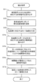
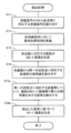
- It is a flowchart which shows the flow in the transmission / reception processing program performed in the ultrasound diagnosing device which concerns on embodiment of this invention. It is a figure which shows the incident wave and reflected wave of the ultrasonic wave which were transmitted toward the mutually different direction. It is a figure which shows the incident wave and reflected wave of the ultrasonic wave which were transmitted toward the mutually different direction. It is a flowchart which shows the flow of a process in the drawing process program which concerns on embodiment of this invention.
- FIG. 1 is a block diagram showing a configuration of an ultrasonic diagnostic apparatus 1 according to an embodiment of the present invention.
- the ultrasonic probe 10 transmits an ultrasonic wave toward a diagnosis site of the subject, and receives a reflected wave (echo) of the ultrasonic wave reflected inside the subject to generate a reception signal.
- the ultrasonic probe 10 includes, for example, a plurality of piezoelectric elements 10a arranged linearly. Each of the piezoelectric elements 10 a generates an ultrasonic wave according to the drive pulse signal supplied from the transmission processing unit 14.
- Each of the piezoelectric elements 10 a receives a reflected wave of an ultrasonic wave reflected in the subject, generates a reception signal that is an electric signal, and supplies the reception signal to the reception processing unit 16.
- the ultrasonic probe 10 may have any scanning method such as a linear type, a convex type, and a sector type.
- the transmission processing unit 14 is connected to each of the piezoelectric elements 10a via signal wiring.
- the transmission processing unit 14 generates a driving pulse signal for driving each piezoelectric element 10a, and supplies the driving pulse signal to each piezoelectric element 10a through a signal wiring.
- the transmission processing unit 14 controls the transmission direction of ultrasonic waves by giving a relative time difference to each of the drive pulse signals supplied to each piezoelectric element 10a.
- the reception processing unit 16 includes an amplifier and an A / D converter (not shown) provided corresponding to each of the piezoelectric elements 10a.
- the reception processing unit 16 amplifies the reception signal generated in each of the piezoelectric elements 10a in an amplifier and converts it into a digital signal in an A / D converter.
- the reception processing unit 16 includes a reception signal memory 16a that stores a reception signal for each piezoelectric element 10a (each channel) converted into a digital signal.
- the phasing addition processing unit 18 provides a relative time difference to the reception signal for each piezoelectric element 10a supplied from the reception processing unit 16 to align the time phases of the reception signals for each piezoelectric element 10a, and then the piezoelectric element 10a.
- a phasing addition process (reception focus process) for adding each received signal is performed.
- the timing at which the ultrasonic waves reflected by a certain reflection point in the subject enter each piezoelectric element 10a does not match. This is because the propagation distance of the reflected wave from a certain reflection point to each piezoelectric element 10a is different for each piezoelectric element.
- the phasing addition processing unit 18 gives a relatively long delay time to the reception signal generated by the piezoelectric element arranged at a position where the distance from the reflection point is relatively short. On the other hand, a relatively short delay time is given to the reception signal generated by the piezoelectric element arranged at a position where the distance from the reflection point is relatively long. As described above, the phasing addition processing unit 18 gives a relative time difference to the reception signals of the respective channels generated for each piezoelectric element 10a to align these time phases, and integrates the reception signals of the phasing channels. Thus, a phasing addition signal is generated.
- the extraction unit 24 reads out the pixel value of each pixel corresponding to the same reflection point in the plurality of B-mode images from each of the plurality of B-mode images generated in the B-mode image generation unit 22, and reads out the pixel values A comparison analysis between a plurality of B-mode images is performed to extract a specific pixel whose pixel value approximates.
- the B-mode image generation unit 22 performs known filtering processing, log compression processing, envelope detection processing, STC (Sensitivity Time Control) processing, interpolation processing, and interpolation processing on the phasing addition signal supplied from the phasing addition processing portion 16.
- a B-mode image in which the signal intensity of the phasing addition signal is converted into luminance is generated by performing scan conversion processing or the like.
- the B-mode image generation unit 22 generates an image signal of the B-mode image so that the position of the specific pixel extracted by the extraction unit 24 can be visually recognized on the B-mode image.
- the B-mode image generation unit 22 generates an image signal so that the luminance of a specific pixel extracted by the extraction unit 24 is sufficiently higher than the luminance of other pixels.
- the B-mode image generation unit 22 may generate an image signal by assigning a color different from other pixels to the pixel extracted by the extraction unit 24.
- the input unit 12 accepts various operation inputs by the user, and is constituted by an input means such as a pointing device such as a mouse or a trackball or a keyboard, for example.
- an input means such as a pointing device such as a mouse or a trackball or a keyboard, for example.
- the user can perform, for example, start and end of transmission / reception of ultrasonic waves, switching of a display image displayed on the monitor 30, designation of a region of interest inside the subject, and the like.
- the monitor 30 has a display screen for displaying the B-mode image based on the image signal supplied from the B-mode image generation unit 22.
- the position of the specific pixel is displayed on the monitor 22 in a manner that can be visually recognized on the B-mode image.
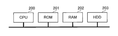
- the transmission processing unit 14, the reception processing unit 16, the phasing addition processing unit 18, the B-mode image generation unit 22, and the extraction unit 24 are as shown in FIG.
- CPU 200 Read Only Memory
- ROM 201 Read Only Memory
- RAM Random Access Memory
- HDD Hard Disk Drive
- the operation of the ultrasonic diagnostic apparatus 1 according to the embodiment of the present invention will be described below. First, a transmission / reception process in which the ultrasonic diagnostic apparatus 1 transmits / receives an ultrasonic wave to generate a reception signal will be described.
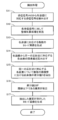
- FIG. 3 is a flowchart showing the flow of processing in the transmission / reception processing program executed by the CPU 200 of the ultrasonic diagnostic apparatus 1.
- This transmission / reception processing program is stored in advance in the ROM 201, and is executed, for example, when the user inputs a predetermined operation to the input unit 12.
- step S1 the transmission processing unit 14 generates a drive pulse signal and supplies it to the ultrasonic probe 10. At this time, the transmission processing unit 14 gives a relative time difference to the drive pulse signal supplied for each piezoelectric element 10a so that the transmission direction of the ultrasonic wave is a predetermined direction.
- the ultrasonic probe 10 transmits ultrasonic waves toward the predetermined direction in the subject.
- An echo by reflection of the ultrasonic beam transmitted from the ultrasonic probe 10 is received by each of the piezoelectric elements 10a.
- Each of the piezoelectric elements 10 a converts the reflected echo into a reception signal that is an electric signal and supplies the reception signal to the reception processing unit 16.
- step S2 the reception processing unit 16 waits for input of the reception signal, and when receiving the reception signal from the ultrasonic probe 10, in step S3, the signal including amplification and A / D conversion for the reception signal of each channel.
- the received signal subjected to the processing is stored in the received signal memory 16a.
- step S4 the transmission processing unit 14 determines whether or not a predetermined number of ultrasonic transmissions have been completed. If the transmission processing unit 14 determines that the transmission of the predetermined number of ultrasonic waves is not completed, the process proceeds to step S5.
- step S5 the transmission processing unit 14 changes the setting of the ultrasonic transmission direction and returns the process to step S1. Thereafter, the processing from step S1 to step S5 is repeatedly executed until the transmission of the predetermined number of ultrasonic waves is completed. Thereby, ultrasonic waves are transmitted in a plurality of directions different from each other, and a plurality of reception signals generated according to each transmission are stored in the reception signal memory 16a.
- the ultrasonic diagnostic apparatus 1 sequentially transmits ultrasonic waves in a plurality of mutually different directions, and receives each of the reception signals generated according to each transmission of the ultrasonic waves as a reception signal memory. 16a. Note that, among the transmissions of ultrasonic waves that are performed a plurality of times, those that are performed so that the transmission direction of the ultrasonic waves is substantially perpendicular to the transmission / reception surface of the ultrasonic probe 10 may be included. In addition, ultrasonic waves may be transmitted in at least two different directions, but ultrasonic waves may be transmitted in three or more different directions.
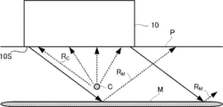
- FIGS. 4A and 4B are diagrams schematically showing an incident wave (solid line) and a reflected wave (broken line) of an ultrasonic wave transmitted from the ultrasonic probe 10 in different directions in the subject P.
- FIG. is there.
- the subject P is formed by the mammary gland structure M extending in a direction substantially parallel to the transmission / reception surface 10S of the ultrasound probe 10 and the calcification of the breast tissue.
- the micro calcification part C with a diameter of 1 mm or less.
- FIG. 4A shows a case where ultrasonic waves are transmitted in a direction substantially perpendicular to the transmission / reception surface 10 ⁇ / b> S of the ultrasonic probe 10.
- the reflection at the surface of large mammary gland M of relatively surface area next to the specular reflection (specular reflection) the traveling direction of the reflected wave R M caused by reflection on the surface of the mammary gland structure M is, ultrasound angle of incidence Depending on the direction.
- the ultrasonic wave in a direction substantially perpendicular to the mammary gland M enters the traveling direction of the reflected wave R M is substantially against receiving surface 10S of the ultrasonic probe 10 The vertical direction.
- the reflected wave R M is to be received by the ultrasonic probe 10.
- the reflection on the surface of the microcalcification portion C having a relatively small surface area is diffuse reflection. Therefore, the reflected wave RC generated by the reflection on the surface of the microcalcification portion C is scattered in various directions and received by the ultrasonic probe 10.
- FIG. 4B shows a case where ultrasonic waves are transmitted in an oblique direction with respect to the transmission / reception surface 10S of the ultrasonic probe 10.
- the ultrasonic wave transmitted from the ultrasonic probe 10 enters the breast structure M from an oblique direction.
- the oblique direction with respect to the transmission and reception surface 10S of the traveling direction the ultrasonic probe 10 of the reflected wave R M caused by reflection on the surface of the mammary gland M.
- the reflected wave RC of the ultrasonic wave reflected from the surface of the microcalcification part C is scattered in various directions. Therefore, similarly to the case shown in FIG. 4A, the reflected wave RC can be received by the ultrasonic probe 10.
- the ultrasonic reflected wave RC reflected on the surface of the microcalcification part C is received by the ultrasonic probe 10 regardless of the transmission direction of the ultrasonic wave. That is, the micro calcification part C is drawn in any of a plurality of B mode images generated corresponding to each transmission of ultrasonic waves transmitted in a plurality of different directions.
- a tissue having a relatively large surface area such as the mammary gland structure M exhibits specular reflectivity with respect to the ultrasonic wave, while a microstructure such as the microcalcification portion C is provided.
- a microstructure such as the microcalcification portion C is drawn using the fact that it exhibits diffuse reflectivity with respect to ultrasonic waves.
- FIG. 5 is a flowchart showing the flow of processing in the rendering processing program executed by the CPU 200 of the ultrasonic diagnostic apparatus 1.
- This rendering processing program is stored in advance in the ROM 201, and is executed, for example, when the user inputs a predetermined operation to the input unit 12.
- the above transmission / reception processing program (see FIG. 3) is executed, and a plurality of reception signals corresponding to the respective transmission directions are already stored in the reception signal memory 16a.
- the reception signal memory 16a it is assumed that in the previous transmission / reception process, ultrasonic waves are transmitted in two different directions, and two reception signals corresponding to the transmissions in the two directions are stored in the reception signal memory 16a.
- step S11 the phasing addition processing unit 18 reads out two reception signals corresponding to the two transmission directions acquired by executing the transmission / reception process from the reception signal memory 16a.
- step S12 the phasing addition processing unit 18 performs phasing addition processing on each of the two reception signals read from the reception signal memory 16a.
- step S13 the B-mode image generation unit 22 performs a known filtering process, a log compression process, and an envelope detection process for each phasing addition signal corresponding to each transmission direction supplied from the phasing addition processing unit 18.
- STC Sesitivity Time Control
- interpolation processing scan conversion processing, and the like are performed to generate two B-mode image signals corresponding to two transmission directions.
- step S14 the extraction unit 24 reads out the pixel value of each pixel corresponding to the same reflection point in the two B-mode images from each of the two B-mode images generated in the B-mode image generation unit 22.
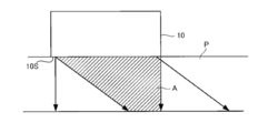
- FIG. 6 illustrates a case where ultrasonic waves are transmitted in the vertical direction and a case where ultrasonic waves are transmitted in an oblique direction with respect to the transmission / reception surface 10 ⁇ / b> S of the ultrasonic probe 10.
- the extraction unit 24 calculates the pixel value of each pixel corresponding to the same (common) reflection point in the area A indicated by hatching in FIG. 6 from each of the two B-mode images corresponding to each transmission direction. read out.
- step S15 the extraction unit 24 derives, for each pixel corresponding to the same reflection point, a difference value D between the plurality of B-mode images of the pixel value of each pixel corresponding to the read same reflection point. That is, the extraction unit 24 performs a process of deriving a pixel value difference value D between two B-mode images corresponding to each transmission direction for each pixel corresponding to the same reflection point.
- the reflected waves R of the ultrasonic waves reflected by the surface of the mammary gland structure M are reflected. Since M is hardly received by the ultrasonic probe 10, the pixel value of each pixel corresponding to each reflection point on the mammary gland structure M is substantially zero in the B-mode image generated in response to the transmission in the oblique direction. . Therefore, the difference value D derived for the pixel value of each pixel corresponding to each reflection point on the mammary gland structure M is a relatively large value.
- the reflected wave R C of the ultrasonic wave reflected by the micro-calcifications C is received by the ultrasonic probe 10 regardless of the transmission direction of the ultrasound. Therefore, the difference value D derived for the pixel value of each pixel corresponding to each reflection point on the microcalcification portion C is a relatively small value.
- step S16 the extraction unit 24 extracts pixels whose difference value D derived in step S15 is equal to or less than a predetermined threshold value. That is, the extraction unit 24 extracts pixels having a relatively small change in pixel value between two B-mode images corresponding to each transmission when ultrasonic waves are transmitted in two different directions. That is, by this process, pixels corresponding to each reflection point on the mammary gland structure M are excluded, while pixels corresponding to each reflection point on the microcalcification portion C are extracted.
- the B mode image generation unit 22 extracts, for example, the pixels extracted by the extraction unit 24 on the B mode image corresponding to the transmission direction specified by the user from the B mode images generated in step S ⁇ b> 13. Reconstruct the B-mode image as specified.
- the B-mode image generation unit 22 generates an image signal of the B-mode image so that the luminance of the pixels extracted by the extraction unit 24 is sufficiently higher than that of other pixels.
- the B-mode image generation unit 22 may generate an image signal by assigning a color different from other pixels to the pixel extracted by the extraction unit 24.
- the B mode image generation unit 22 supplies the generated image signal to the monitor 30. As a result, a B-mode image in which the position, size, and range of the microcalcification unit 30 are clearly displayed is displayed on the monitor 30.
- the ultrasonic diagnostic apparatus 1 transmits ultrasonic waves in a plurality of directions different from each other in the subject, and generates a plurality of B-mode images based on reception signals acquired according to each transmission.
- a difference value D between a plurality of B-mode images of a pixel value of each pixel corresponding to the same reflection point in each B-mode image is derived, and pixels whose derived difference value D is equal to or less than a predetermined threshold are extracted. .
- pixels corresponding to each reflection point on the mammary gland structure M are excluded, while pixels corresponding to each reflection point on the microcalcification part C are extracted. Therefore, according to the ultrasonic diagnostic apparatus 1 according to the embodiment of the present invention, it is possible to improve the visualization performance of a microstructure such as a microcalcification part in a subject.
- a specific pixel is extracted by comparing and analyzing the pixel value of a single pixel between a plurality of B-mode images is illustrated, but the present invention is not limited to this.
- a specific pixel group may be extracted by comparing and analyzing pixel values representing a pixel group composed of a plurality of adjacent pixels between a plurality of B-mode images.
- the extraction unit 24 may derive a difference value D for the average value of the pixel values of a plurality of adjacent pixels, and extract a pixel group in which the difference value D is equal to or less than a predetermined value.
- FIG. 7 is a flowchart showing the flow of processing in the rendering processing program according to the second embodiment of the present invention.
- the program is obtained by replacing step S14 in the rendering processing program according to the first embodiment shown in FIG. 5 with step S14a.
- step S14 in the rendering processing program according to the first embodiment shown in FIG. 5
- step S14a parts different from the rendering processing program according to the first embodiment will be described.
- step S14a the extraction unit 24 selects each pixel corresponding to the same reflection point in the plurality of B-mode images from each of the plurality of B-mode images corresponding to each transmission direction generated in the B-mode image generation unit 22. Among these pixel values, a pixel value greater than or equal to a predetermined value is read. In step S15, the extraction unit 24 derives a difference value D between the plurality of B-mode images of the pixel value read out in this way for each pixel corresponding to the same reflection point.
- the condition is that the pixel value from which the difference value D is derived is equal to or greater than a predetermined value.
- the pixel value corresponding to the microcalcification portion C is a relatively large value. That is, the pixel corresponding to the minute lime C has a relatively high luminance on the B-mode image. Therefore, in the rendering processing program according to the present embodiment, by setting a lower limit value for the pixel value of the pixel extracted by the extraction unit 24, it is possible to prevent pixels with relatively low luminance from being extracted. Thereby, it becomes possible to aim at the further improvement of the drawing precision of the micro calcification part C.
- FIG. 8 is a flowchart showing the flow of processing in the rendering processing program according to the third embodiment of the present invention.
- the rendering processing program according to the first and second embodiments described above transmits ultrasound in two different directions, and renders a microstructure based on two B-mode images corresponding to each transmission. there were.
- the rendering processing program according to the third embodiment transmits ultrasonic waves in three or more directions different from each other, and converts the microstructures based on three or more B-mode images corresponding to the respective transmissions. It can be applied when rendering.
- the rendering program according to the third embodiment is obtained by replacing steps S15 and S16 in the rendering processing program according to the first embodiment shown in FIG. 5 with steps S15b and S16b, respectively.
- steps S15b and S16b respectively.
- step S15b the extraction unit 24 reads the pixel values of each pixel corresponding to the same reflection point, read from each of the plurality of B mode images corresponding to each of the plurality of transmission directions, among the plurality of B mode images.
- An index value Z indicating the magnitude of is derived for each pixel corresponding to the same reflection point.
- the index value Z indicating the magnitude of variation in pixel values for example, a variance value, a standard deviation, a difference value between the maximum value and the minimum value, or the like can be applied.
- step S16b the extraction unit 24 extracts pixels whose index value Z derived for each pixel corresponding to the same reflection point is equal to or less than a predetermined threshold value. That is, the extraction unit 24 extracts pixels with relatively small variations in pixel values between a plurality of B-mode images corresponding to each transmission when ultrasonic waves are transmitted in a plurality of different directions. That is, by this process, pixels corresponding to each reflection point on the mammary gland structure M are excluded, while pixels corresponding to each reflection point on the microcalcification portion C are extracted. Therefore, according to the rendering processing program according to the third embodiment, it is possible to improve the rendering accuracy of the microcalcification portion C as in the first embodiment.
- a specific pixel is extracted by comparing and analyzing the pixel value of a single pixel between a plurality of B-mode images is illustrated, but the present invention is not limited to this.
- a specific pixel group may be extracted by comparing and analyzing pixel values representing a pixel group composed of a plurality of adjacent pixels between a plurality of B-mode images.
- the extraction unit 24 may derive a variation index value Z for the average value of each pixel value of a plurality of adjacent pixels, and extract a pixel group in which the index value Z is equal to or less than a predetermined value.
- the process in step S14 in the rendering process program according to the present embodiment can be replaced with the process in step S14a in the rendering process program according to the second embodiment shown in FIG.
- FIG. 9 is a flowchart showing the flow of processing in the rendering processing program according to the fourth embodiment of the present invention.
- the rendering program according to the fourth embodiment is obtained by replacing steps S14 to S17 in the rendering processing program according to the first embodiment shown in FIG. 5 with steps S14c to S17c, respectively.
- steps S14 to S17 in the rendering processing program according to the first embodiment shown in FIG. 5 are replaced with steps S14c to S17c, respectively.
- parts different from the rendering processing program according to the first embodiment will be described.
- step S ⁇ b> 14 c the extraction unit 24 is adjacent to the same reflection point in the plurality of B-mode images from each of the plurality of B-mode images corresponding to the transmission directions generated in the B-mode image generation unit 22.
- the pixel value is read out for each of the pixel groups composed of a plurality of pixels.
- step S15c the extraction unit 24 derives a correlation value A between a plurality of B-mode images of the pixel values of the read pixel group for each pixel group corresponding to the same reflection point.
- the mammary gland structure M since the mammary gland structure M has specular reflection, the mammary gland structure M is depicted in a plurality of B-mode images generated corresponding to each transmission of ultrasonic waves transmitted in a plurality of different directions. It may or may not be rendered. Accordingly, when the correlation value A is derived among a plurality of B-mode images corresponding to each transmission direction for the pixel values of the pixel group corresponding to each reflection point on the mammary gland structure M, the value becomes a relatively small value. On the other hand, since the micro calcification part C has diffuse reflectance, the micro calcification part is included in any of the plurality of B-mode images generated corresponding to the respective transmissions of ultrasonic waves transmitted in a plurality of different directions.
- step S16c the extraction unit 24 extracts a pixel group in which the correlation value A derived for each pixel group in step S15c is equal to or greater than a predetermined threshold value. That is, the extraction unit 24 uses a pixel group (that is, each pixel value) having a relatively large correlation value A between a plurality of B-mode images corresponding to each transmission when ultrasonic waves are transmitted in a plurality of different directions. Are extracted). Thereby, the pixel group corresponding to each reflection point on the micro calcification part C is extracted. That is, by this process, the pixel group corresponding to each reflection point on the mammary gland structure M is excluded, while the pixel group corresponding to each reflection point on the microcalcification part C is extracted.
- the B-mode image generation unit 22 specifies the pixel group extracted by the extraction unit 24 on the B-mode image corresponding to the transmission direction specified by the user, for example, among the B-mode images generated in step S ⁇ b> 13.
- the B-mode image is reconstructed as follows.
- the B-mode image generation unit 22 may generate an image signal so that the luminance of the pixel group extracted by the extraction unit 24 is sufficiently higher than other pixels.
- the B-mode image generation unit 22 may generate an image signal by assigning a color different from other pixels to the pixel group extracted by the extraction unit 24.
- the B mode image generation unit 22 supplies the image signal of the reconstructed B mode image to the monitor 30.
- step S14c in the rendering processing program the extraction unit 24 extracts the plurality of B modes from each of the plurality of B mode images corresponding to the transmission directions generated by the B mode image generation unit 22.
- the extraction unit 24 extracts the plurality of B modes from each of the plurality of B mode images corresponding to the transmission directions generated by the B mode image generation unit 22.
- FIG. 10 is a flowchart showing the flow of processing in the rendering processing program according to the fifth embodiment of the present invention.
- the rendering program according to the fifth embodiment is obtained by replacing steps S15 and S16 in the rendering processing program according to the first embodiment shown in FIG. 5 with steps S15d and S16d, respectively.
- steps S15d and S16d respectively.
- step S15d the extraction unit 24 derives the minimum pixel value B min between a plurality of B-mode images for each pixel corresponding to the same reflection point.
- step S16d the extraction unit 24 extracts pixels whose minimum pixel value B min between the B-mode images derived for each pixel corresponding to the same reflection point is equal to or greater than a predetermined threshold value.
- the mammary gland structure M since the mammary gland structure M has specular reflection, the mammary gland structure M is included in a plurality of B-mode images generated in response to transmissions of ultrasonic waves transmitted in a plurality of different directions. It may or may not be rendered. When the mammary gland structure M is not drawn, the pixel value corresponding to each reflection point on the mammary gland structure M is substantially zero. On the other hand, since the micro calcification part C has diffuse reflectance, the micro calcification part is included in any of the plurality of B-mode images generated corresponding to the respective transmissions of ultrasonic waves transmitted in a plurality of different directions. There is a high possibility that C is drawn.
- the minimum pixel value Bmin between the plurality of B-mode images of the pixels corresponding to the respective reflection points on the mammary gland structure M is likely to be substantially zero.
- the minimum pixel value B min between the plurality of B-mode images of the pixels corresponding to each reflection point on the micro calcification portion C is a value larger than zero.
- pixels whose minimum pixel value B min between B-mode images derived for each pixel corresponding to the same reflection point is greater than or equal to a predetermined threshold are extracted. Therefore, it is possible to exclude pixels corresponding to each reflection point on the mammary gland structure M and to extract pixels corresponding to each reflection point on the microcalcification portion C. Thereby, it becomes possible to improve the drawing accuracy of the microcalcification part C.
- step S14 in the rendering processing program according to the present embodiment can be replaced with the processing in step S14a in the rendering processing program according to the second embodiment shown in FIG.
- the pixel or the pixel group extracted by the extraction unit 24 is illustrated as being superimposed on the B-mode image displayed on the monitor 30, but the extraction unit 24 is illustrated. Only the pixel or pixel group extracted by the above may be displayed on the monitor 30 so as to clearly indicate these positions.
- FIG. 11 is a flowchart showing the flow of processing in the rendering processing program according to the sixth embodiment of the present invention.
- the rendering program according to the sixth embodiment is obtained by replacing steps S15 to S17 in the rendering processing program according to the first embodiment shown in FIG. 5 with steps S15e and S16e.
- steps S15 to S17 in the rendering processing program according to the first embodiment shown in FIG. 5
- steps S15e and S16e are replaced by replacing steps S15e and S16e.
- step S15e the extraction unit 24 extracts, for each pixel corresponding to the same reflection point, a pixel having a minimum pixel value between a plurality of B-mode images.
- step S16e the B-mode image generation 24 reconstructs the B-mode image using the pixel having the minimum pixel value extracted by the extraction unit 24 in step S15e, and monitors the image signal of the reconstructed B-mode image. 30.
- the mammary gland structure M since the mammary gland structure M has specular reflection, the mammary gland structure M is included in a plurality of B-mode images generated in response to transmissions of ultrasonic waves transmitted in a plurality of different directions. It may or may not be rendered. When the mammary gland structure M is not drawn, the pixel value corresponding to each reflection point on the mammary gland structure M is substantially zero. On the other hand, since the micro calcification part C has diffuse reflectance, the micro calcification part is included in any of the plurality of B-mode images generated corresponding to the respective transmissions of ultrasonic waves transmitted in a plurality of different directions. There is a high possibility that C is drawn.
- a pixel having the smallest pixel value is extracted between a plurality of B-mode images generated in response to each transmission of ultrasonic waves, and the extracted pixel To reconstruct the B-mode image.
- a pixel value zero is assigned to the pixel corresponding to each reflection point on the mammary gland structure M, while a pixel value greater than zero is assigned to the pixel corresponding to each reflection point on the microcalcification part C.
- the minute calcification portion C can be depicted on the monitor 30. Therefore, according to the rendering processing program according to the sixth embodiment, it is possible to improve the rendering accuracy of the microcalcification portion C.
- the ultrasonic diagnostic apparatus transmits ultrasonic waves in two or more directions different from each other, and a microstructure based on a plurality of B-mode images generated according to each transmission It was to depict.
- the ultrasonic diagnostic apparatus according to the seventh embodiment has a plurality of directions different from each other with respect to one reception signal generated in response to transmission of an ultrasonic wave transmitted in any one direction.
- a phasing addition process (reception focus process) is performed along each to generate a plurality of B-mode images corresponding to each of the plurality of reception focus directions, and a microstructure is formed based on the plurality of B-mode images.
- FIG. 12A and 12B show a mode in which the phasing addition process is performed on the received signal along different reception focus directions.
- FIG. 12A shows a case where the reception focus direction is set in a direction perpendicular to the transmission / reception surface of the ultrasonic probe 10.
- the timing at which the reflected wave generated at the reflection point R shown in FIG. 12A is received by each piezoelectric element 10a is shown by each plot in the figure.
- the reception timing of the reflected wave generated at the reflection point R differs for each piezoelectric element 10a.
- the phasing addition processing unit 18 generates, as a phasing addition signal, a sum of signal values on the plots corresponding to the reflection points R in the reception signals a 1 to a 11 generated by the piezoelectric elements 10a.
- the reception focus direction is a direction perpendicular to the transmission / reception surface of the ultrasonic probe 10
- the reflection point R is moved in the direction perpendicular to the transmission / reception surface of the ultrasonic probe 10 to generate a phasing addition signal at each time. .
- FIG. 12B shows a case where the reception focus direction is set obliquely with respect to the transmission / reception surface of the ultrasonic probe 10.
- the timing at which the reflected wave generated at the reflection point R shown in FIG. 12B is received by each piezoelectric element 10a is shown in each plot in the drawing.
- the phasing addition processing unit 18 generates, as a phasing addition signal, a sum of signal values on each plot corresponding to the reflection points R in the reception signals a 1 to a 11 generated by the piezoelectric elements 10a.
- the reflection point R is moved in an oblique direction with respect to the transmission / reception surface of the ultrasonic probe 10 to generate a phasing addition signal at each time.
- the combination of signal values to be added on the reception signals a 1 to a 11 changes, so that the generated phasing addition signal is different. It becomes.
- a plurality of phasing addition signals generated by performing phasing addition processing along each of a plurality of different directions on a single received signal are sequentially transmitted in a plurality of different directions.
- This is equivalent to a plurality of phasing addition signals generated by performing phasing addition processing on each of the plurality of reception signals generated in response to each transmission of the generated ultrasonic waves.
- setting the reception focus direction to a certain direction and performing the phasing addition processing corresponds to receiving a reflected wave of the ultrasonic wave reflected in that direction. Therefore, by performing the phasing addition process along each of the plurality of reception focus directions, the reflected wave of the ultrasonic wave reflected toward each of the plurality of directions can be captured.
- a plurality of B-mode images corresponding to each transmission by transmitting ultrasonic waves in a plurality of different directions in the rendering processes according to the first to sixth embodiments instead of the process of generating the signal, the ultrasonic wave is transmitted only in a single direction, and the received signal obtained thereby is subjected to phasing addition processing along a plurality of reception focus directions different from each other.
- a rendering process including a process of generating a plurality of B-mode images corresponding to the focus direction is executed.
- FIG. 13 is a flowchart showing the flow of processing in the rendering processing program according to the seventh embodiment of the present invention.
- the rendering processing program Before the rendering processing program is executed, at least one ultrasonic transmission / reception is performed, and a reception signal generated in response to the transmission / reception of the ultrasonic wave is already stored in the reception signal memory 16a.
- step S31 the phasing addition processing unit 18 reads the received signal from the received signal memory 16a.
- step S32 the phasing addition processing unit 18 performs phasing addition processing along each of a plurality of predetermined reception focus directions on the reception signal read from the reception signal memory 16a, and receives each reception focus.
- a plurality of phasing addition signals corresponding to each of the directions are generated.
- the phasing addition processing is performed along two different reception focus directions.
- step S33 the B-mode image generation unit 22 performs known filtering processing, log compression processing, envelope detection on each of the phasing addition signals corresponding to the reception focus directions supplied from the phasing addition processing unit 18. Processing, STC (Sensitivity Time Control) processing, interpolation processing, scan conversion processing, and the like are performed to generate two B-mode image signals corresponding to each of the two reception focus directions.
- STC Sensitivity Time Control
- step S34 the extraction unit 24 reads out the pixel value of each pixel corresponding to the same reflection point in the two B-mode images from each of the two B-mode images generated in the B-mode image generation unit 22.
- step S35 the extraction unit 24 derives, for each pixel corresponding to the same reflection point, a difference value D between the two B-mode images of the pixel value of each pixel corresponding to the read same reflection point.
- step S36 the extraction unit 24 extracts pixels whose difference value D derived in step S35 is equal to or smaller than a predetermined threshold value.
- the extraction unit 24 extracts pixels having a relatively small change in pixel value between two B-mode images corresponding to two different reception focus directions. By this process, pixels corresponding to each reflection point on the mammary gland structure M are excluded, while pixels corresponding to each reflection point on the microcalcification portion C are extracted.
- the B-mode image generation unit 22 reconstructs the B-mode image so that the pixels extracted by the extraction unit 24 are clearly shown on the B-mode image generated in the previous step S33.
- the B-mode image generation unit 22 may generate an image signal so that the luminance of the pixels extracted by the extraction unit 24 is sufficiently higher than other pixels.
- the B-mode image generation unit 22 may generate an image signal by assigning a color different from other pixels to the pixel extracted by the extraction unit 24.
- the B mode image generation unit 22 supplies the generated image signal to the monitor 30. As a result, a B-mode image in which the position, size, and range of the microcalcification unit 30 are clearly displayed is displayed on the monitor 30.
- step S34 in the rendering processing program according to the present embodiment can be replaced with step S14a in the rendering processing program according to the second embodiment.
- Step S35 and Step S36 in the rendering processing program according to the present embodiment can be replaced with Step S15b and Step S16b in the rendering processing program according to the third embodiment, respectively.
- steps S34 to S37 in the rendering processing program according to the present embodiment can be replaced with steps S14c to S17c in the rendering processing program according to the fourth embodiment, respectively.
- Step S35 and Step S36 in the rendering processing program according to the present embodiment can be replaced with Step S15d and Step S16d in the rendering processing program according to the fifth embodiment, respectively.
- Steps S35 to S37 in the rendering processing program according to the present embodiment can be replaced with Steps S15e and S16e according to the sixth embodiment.
- the pixel extracted by the extraction unit 24 is illustrated as being superimposed on the B-mode image displayed on the monitor 30. However, only the pixel extracted by the extraction unit 24 is positioned at that position. May be displayed on the monitor 30 so as to be clearly indicated.
- the focus direction is included. This makes it possible to efficiently eliminate pixels corresponding to each reflection point on the mammary gland structure M, and as a result, it is possible to improve the rendering accuracy of the microcalcification part C.
- the present invention is also applicable to the case where the microcalcification portion generated in other parts such as the thyroid gland and the prostate is depicted. It is possible to apply.
- the present invention can be applied not only to the microcalcification part but also to drawing other microstructures such as microclips that show diffuse reflectivity with respect to ultrasonic waves.
- a known filtering process, a log compression process, and an envelope detection process are performed on the phasing addition signal generated by performing the phasing addition process corresponding to a plurality of different transmission directions or reception directions.
- a B-mode image generated by performing STC processing, interpolation processing, scan conversion processing, etc. a pixel structure value of each pixel corresponding to the same reflection point is subjected to comparative analysis to extract a micro structure such as micro calcification
- a micro structure such as micro calcification
- An index value to be derived may be derived, and a comparative analysis of the index value may be performed to extract a microstructure such as microcalcification.
- the reception direction and the transmission direction when transmitting ultrasonic waves in a plurality of different directions, the reception direction and the transmission direction may be the same or different.
Landscapes
- Health & Medical Sciences (AREA)
- Life Sciences & Earth Sciences (AREA)
- Engineering & Computer Science (AREA)
- Physics & Mathematics (AREA)
- Molecular Biology (AREA)
- Heart & Thoracic Surgery (AREA)
- Veterinary Medicine (AREA)
- Public Health (AREA)
- Biophysics (AREA)
- Nuclear Medicine, Radiotherapy & Molecular Imaging (AREA)
- Pathology (AREA)
- Radiology & Medical Imaging (AREA)
- Biomedical Technology (AREA)
- General Health & Medical Sciences (AREA)
- Medical Informatics (AREA)
- Animal Behavior & Ethology (AREA)
- Surgery (AREA)
- Computer Networks & Wireless Communication (AREA)
- Remote Sensing (AREA)
- General Physics & Mathematics (AREA)
- Radar, Positioning & Navigation (AREA)
- Computer Vision & Pattern Recognition (AREA)
- Ultra Sonic Daignosis Equipment (AREA)
Abstract
超音波診断装置は、反射点から互いに異なる複数の方向に向けて反射された超音波の反射波に基づいて複数の方向の各々に対応する複数の画像を生成する画像生成手段と、画像生成手段によって生成された複数の画像における同一の反射点に対応する各画素の画素値の比較解析を行って、画素値の近似する特定の画素を抽出する抽出手段と、抽出手段によって抽出された特定の画素を表示する表示手段と、を含む。
Description
本発明は、超音波の送受信によって被検体の断層画像を生成する超音波診断装置、画像描出方法およびプログラムに関する。
超音波プローブから被検体に超音波を送信し、被検体内部からの反射波に基づいて被検体の断層画像を生成する超音波診断装置が知られている。このような超音波診断装置において、互いに異なる複数の方向に超音波を送信し、各送信によって得られた受信信号に基づいて1つの断層画像を生成する技術が知られている。
例えば特許文献1(特開2012-213606号公報)には、穿刺針が挿入された被検体に方位方向に対して垂直な方向に超音波送信を行なう第1のスキャンと、第1のスキャンの際の方向とは異なる複数の方向それぞれで超音波送信を行なう第2のスキャンとを行うことが記載されている。そして、この特許文献1に記載の装置では、第1のスキャンにより超音波プローブが受信した反射波を用いて第1の超音波画像を生成し、第2のスキャンにより超音波プローブ1が受信した反射波を用いて複数の方向ごとの超音波画像である第2の超音波画像群を生成する。そして、第2の超音波画像群の中から、所定の条件に合致する画像を第3の超音波画像として選択し、第3の超音波画像から穿刺針領域を抽出し、抽出された穿刺針領域に基づいて、針画像を生成し、第1の超音波画像と針画像との合成画像を生成する。
現在、乳房内に生じた微小石灰化部に対する描出性能は、X線を用いるマンモグラフィ装置の方が、超音波診断装置に対して優位であるとされている。これは、超音波画像において、乳腺構造と微小石灰化部の双方が比較的高輝度な反射点として描出されてしまい、微小石灰部の画像が乳腺構造の画像に埋もれてしまうからである。
超音波診断では、X線を使用するマンモグラフィ装置のような被爆リスクがないことから、超音波診断装置における微小石灰化部の描出性能の向上が望まれている。現在、微小石灰化部の描出性能の向上に対する検討が様々なされているが未だ十分ではない。
本発明は、上記した点に鑑みてなされたものであり、被検体内における微小石灰化部等の微小構造体の描出性能を従来よりも向上させることができる超音波診断装置、画像描出方法およびプログラムを提供する。
本発明の第1の観点によれば、反射点から互いに異なる複数の方向に向けて反射された超音波の反射波に基づいて前記複数の方向の各々に対応する複数の画像を生成する画像生成手段と、前記画像生成手段によって生成された前記複数の画像における同一の反射点に対応する各画素の画素値の比較解析を行って、画素値の近似する特定の画素を抽出する抽出手段と、前記抽出手段によって抽出された前記特定の画素を表示する表示手段と、を含む超音波診断装置が提供される。
本発明の第2の観点によれば、前記抽出手段は、前記画像生成手段によって生成された前記複数の画像における同一の反射点に対応する各画素のうち、前記複数の画像間における画素値の差分値またはばらつきの大きさを示す指標値が所定の閾値以下となる画素を前記特定の画素として抽出する第1の観点による超音波診断装置が提供される。
本発明の第3の観点によれば、前記抽出手段は、前記画像生成手段によって生成された前記複数の画像における同一の反射点に対応する各画素のうち、前記複数の画像間における画素値の相関値が所定の閾値以上となる画素を前記特定の画素として抽出する第1の観点による超音波診断装置が提供される。
本発明の第4の観点によれば、前記抽出手段は、前記画像生成手段によって生成された前記複数の画像の各々において、所定の閾値以上の画素値を有する画素を前記特定の画素として抽出する第2または第3の観点による超音波診断装置が提供される。
本発明の第5の観点によれば、前記抽出手段は、前記画像生成手段によって生成された前記複数の画像における同一の反射点に対応する各画素のうち、前記複数の画像間における最小の画素値が所定の閾値以上である画素を抽出する第1の観点による超音波診断装置が提供される。
本発明の第6の観点によれば、前記表示手段は、前記抽出手段によって抽出された画素のみを表示する第1乃至第5のいずれかの観点による超音波診断装置が提供される。
本発明の第7の観点によれば、前記表示手段は、前記画像生成手段によって生成されたいずれかの画像上に前記抽出手段によって抽出された画素を視認可能に表示する第1乃至第5のいずれかの観点による超音波診断装置が提供される。
本発明の第8の観点によれば、前記抽出手段は、前記画像生成手段によって生成された前記複数の画像における同一の反射点に対応する各画素うち、前記複数の画像間で最小の画素値を有する画素を抽出し、前記表示手段は、前記抽出手段によって抽出された画素によって構成される画像を表示する第1の観点による超音波診断装置が提供される。
本発明の第9の観点によれば、前記画像生成手段は、互いに異なる複数の方向に向けて順次送信された超音波の各送信に応じて生成された複数の受信信号の各々に基づいて、前記複数の方向の各々に対応する複数の画像を生成する第1乃至第8のいずれかの観点による超音波診断装置が提供される。
本発明の第10の観点によれば、超音波の送信に応じて生成された受信信号に対して互いに異なる複数の方向の各々に沿って整相加算処理を行って、前記複数の方向の各々に対応する複数の整相加算信号を生成する整相加算手段を更に含み、前記画像生成手段は、前記整相加算手段によって生成された前記複数の整相加算信号の各々に基づいて、前記複数の方向の各々に対応する複数の画像を生成する第1乃至第8のいずれかの観点による超音波診断装置が提供される。
本発明の第11の観点によれば、前記画像生成手段は、1の方向および前記1の方向に対して90°傾いた他の方向に向けて送信された超音波の各送信に対応する少なくとも2つの画像を生成する第9の観点による超音波診断装置が提供される。
本発明の第12の観点によれば、前記整相加算手段は、超音波の送信に応じて生成された受信信号に対して1の方向および前記1の方向に対して90°傾いた他の方向の各々に沿って整相加算処理を行って、前記1の方向および前記他の方向の各々に対応する少なくとも2つの整相加算信号を生成する第10の観点による超音波診断装置が提供される。
本発明の第13の観点によれば、反射点から互いに異なる複数の方向に向けて反射された超音波の反射波に基づいて前記複数の方向の各々に対応する複数の画像を生成することと、前記生成された複数の画像における同一の反射点に対応する各画素の画素値の比較解析を行って、画素値の近似する特定の画素を抽出することと、前記抽出された特定の画素を表示することと、を含む画像描出方法が提供される。
本発明の第14の観点によれば、コンピュータを、反射点から互いに異なる複数の方向に向けて反射された超音波の反射波に基づいて前記複数の方向の各々に対応する複数の画像を生成する画像生成手段と、前記画像生成手段によって生成された前記複数の画像における同一の反射点に対応する各画素の画素値の比較解析を行って、画素値の近似する特定の画素を抽出する抽出手段と、前記抽出手段によって抽出された前記特定の画素を表示する表示手段と、として機能させるためのプログラムが提供される。
本発明に係る超音波診断装置、画像描出方法およびプログラムによれば、被検体内における微小石灰化部等の微小構造体の描出性能を従来よりも向上させることが可能となる。
以下、本発明の実施形態に係る超音波診断装置について図面を参照しつつ説明する。
[第1の実施形態]
図1は、本発明の実施形態に係る超音波診断装置1の構成を示すブロック図である。超音波プローブ10は、被検体の診断部位に向けて超音波を送信するとともに、被検体の内部で反射された超音波の反射波(エコー)を受信して受信信号を生成する。超音波プローブ10は、例えば直線状に配列された複数の圧電素子10aを含んでいる。圧電素子10aの各々は、送信処理部14から供給される駆動パルス信号に応じて超音波を発生させる。また、圧電素子10aの各々は、被検体内で反射された超音波の反射波を受信して電気信号である受信信号を生成し、これを受信処理部16に供給する。なお、超音波プローブ10は、リニア型、コンベックス型、セクタ型等のいずれのスキャン方式を有するものであってもよい。
[第1の実施形態]
図1は、本発明の実施形態に係る超音波診断装置1の構成を示すブロック図である。超音波プローブ10は、被検体の診断部位に向けて超音波を送信するとともに、被検体の内部で反射された超音波の反射波(エコー)を受信して受信信号を生成する。超音波プローブ10は、例えば直線状に配列された複数の圧電素子10aを含んでいる。圧電素子10aの各々は、送信処理部14から供給される駆動パルス信号に応じて超音波を発生させる。また、圧電素子10aの各々は、被検体内で反射された超音波の反射波を受信して電気信号である受信信号を生成し、これを受信処理部16に供給する。なお、超音波プローブ10は、リニア型、コンベックス型、セクタ型等のいずれのスキャン方式を有するものであってもよい。
送信処理部14は、圧電素子10aの各々に信号配線を介して接続されている。送信処理部14は、各圧電素子10aを駆動するための駆動パルス信号を生成し、信号配線を介して圧電素子10aの各々に供給する。また、送信処理部14は、各圧電素子10aに供給する駆動パルス信号の各々に相対的な時間差を与えることによって超音波の送信方向を制御する。
受信処理部16は、圧電素子10aの各々に対応して設けられた図示しない増幅器およびA/D変換器を含んでいる。受信処理部16は、圧電素子10aの各々において生成された受信信号を増幅器において増幅し、A/D変換器においてデジタル信号に変換する。また、受信処理部16は、デジタル信号に変換された圧電素子10a毎(チャンネル毎)の受信信号を記憶する受信信号メモリ16aを有している。
整相加算処理部18は、受信処理部16から供給される圧電素子10a毎の受信信号に相対的な時間差を与えることにより圧電素子10a毎の受信信号の時相を揃えた後、圧電素子10a毎の受信信号を加算する整相加算処理(受信フォーカス処理)を行う。被検体内のある反射点で反射された超音波が各圧電素子10aに入射するタイミングは一致しない。これは、ある反射点から各圧電素子10aに至る反射波の伝搬距離が圧電素子毎に相違するからである。整相加算処理部18は、反射点からの距離が比較的短い位置に配置された圧電素子が生成する受信信号に対して比較的長い遅延時間を与える。一方、反射点からの距離が比較的長い位置に配置された圧電素子が生成する受信信号に対して比較的短い遅延時間を与える。このように、整相加算処理部18は、圧電素子10a毎に生成される各チャンネルの受信信号に相対的な時間差を与えてこれらの時相を揃え、整相したチャンネル毎の受信信号を積算して整相加算信号を生成する。
抽出部24は、Bモード画像生成部22において生成された、複数のBモード画像の各々から、複数のBモード画像における同一の反射点に対応する各画素の画素値を読み出し、読み出した画素値の複数のBモード画像間における比較解析を行って画素値の近似する特定の画素を抽出する。
Bモード画像生成部22は、整相加算処理部16から供給される整相加算信号に対して公知のフィルタリング処理、Log圧縮処理、包絡線検波処理、STC(Sensitivity Time Control)処理、補間処理及び走査変換処理などを施し、整相加算信号の信号強度を輝度に変換したBモード画像を生成する。このとき、Bモード画像生成部22は、抽出部24によって抽出された特定の画素の位置を、Bモード画像上において視認できるようにBモード画像の画像信号を生成する。例えば、Bモード画像生成部22は、抽出部24によって抽出された特定の画素の輝度を、他の画素の輝度よりも十分に高くなるように画像信号を生成する。または、Bモード画像生成部22は、抽出部24によって抽出された画素に、他の画素とは異なる色を割り当てて画像信号を生成してもよい。
入力部12は、ユーザによる各種の操作入力を受け付けるものであり、例えば、マウスやトラックボールなどのポインティングデバイスやキーボードなどの入力手段によって構成されるものである。ユーザは、入力部12を操作することにより、例えば、超音波の送受信の開始や終了、モニタ30に表示する表示画像の切替、被検体内部の着目領域の指定などを行うことができる。
モニタ30は、Bモード画像生成部22から供給される画像信号に基づいて、Bモード画像を表示する表示画面を有する。抽出部24によって特定の画素が抽出された場合には、Bモード画像上に当該特定の画素の位置が視認可能な態様でモニタ22上に表示される。
なお、本実施形態に係る超音波診断装置1において、送信処理部14、受信処理部16、整相加算処理部18、Bモード画像生成部22および抽出部24は、図2に示すように、CPU200と、CPU200において実行される各種プログラムを記憶したROM201(Read Only Memory)と、CPU200における演算処理に供されるデータ等を一時的に保存するRAM(Random Access Memory)202と、生成した画像データ等を保存しておくためのHDD(Hard Disk Drive)203と、を含むコンピュータを含んで構成されている。
以下に、本発明の実施形態に係る超音波診断装置1の作用について説明する。はじめに、超音波診断装置1が超音波の送受信を行って受信信号を生成する送受信処理について説明する。
図3は、超音波診断装置1のCPU200によって実行される送受信処理プログラムにおける処理の流れを示すフローチャートである。この送受信処理プログラムは、ROM201に予め格納されおり、例えば、ユーザが入力部12に対して所定の操作入力を行うと実行される。
ステップS1において、送信処理部14は、駆動パルス信号を生成してこれを超音波プローブ10に供給する。このとき、送信処理部14は、超音波の送信方向が所定の方向となるように、圧電素子10a毎に供給する駆動パルス信号に相対的な時間差を付与する。
これにより、超音波プローブ10は、被検体内の上記所定の方向に向けて超音波を送信する。超音波プローブ10から送信された超音波ビームの反射によるエコーは、圧電素子10aの各々において受信される。圧電素子10aの各々は、反射エコーを電気信号である受信信号に変換して受信処理部16に供給する。
ステップS2において、受信処理部16は、受信信号の入力待ちを行い、超音波プローブ10から受信信号を受信すると、ステップS3において、各チャンネルの受信信号に対して増幅およびA/D変換を含む信号処理を施し、信号処理を施した受信信号を受信信号メモリ16aに格納する。
ステップS4において、送信処理部14は、所定の回数の超音波の送信が完了したか否かを判定する。送信処理部14は、所定の回数の超音波の送信が完了していないと判定した場合には、処理をステップS5に移行する。
ステップS5において、送信処理部14は、超音波の送信方向の設定を変更して処理をステップS1に戻す。その後、ステップS1からステップS5の処理が、上記所定の回数の超音波の送信が完了するまで繰り返し実行される。これにより、互いに異なる複数の方向に超音波が送信され、各送信に応じて生成された複数の受信信号が受信信号メモリ16aに格納される。
このように、本実施形態に係る超音波診断装置1は、互いに異なる複数の方向に向けて超音波を順次送信し、超音波の各送信に応じて生成された受信信号の各々を受信信号メモリ16aに格納する。なお、複数回に亘り行われる超音波の送信のうち、超音波の送信方向が超音波プローブ10の送受信面に対して略垂直となるようして行われるものが含まれていてもよい。また、少なくとも互いに異なる2つの方向に超音波の送信を行えばよいが、互いに異なる3つ以上の方向に超音波の送信を行ってもよい。
図4Aおよび図4Bは、超音波プローブ10から被検体P内の互いに異なる方向に向けて送信された超音波の入射波(実線)と反射波(破線)とを、模式的に示した図である。被検体Pは、図4Aおよび図4Bに示すように、超音波プローブ10の送受信面10Sに対して略平行な方向に延在する乳腺構造Mと、乳房組織が石灰化することにより形成された、例えば直径1mm以下の微小石灰化部Cとを含んでいるものとする。
図4Aには、超音波プローブ10の送受信面10Sに対して略垂直方向に超音波が送信された場合が示されている。ここで、比較的表面積の大きい乳腺構造Mの表面での反射は正反射(鏡面反射)となり、乳腺構造Mの表面での反射により生じた反射波RMの進行方向は、超音波の入射角に応じた方向となる。従って、図4Aに示すように、乳腺構造Mに対して略垂直方向に超音波が入射する場合には、その反射波RMの進行方向は、超音波プローブ10の送受信面10Sに対して略垂直な方向となる。すなわち、この場合、反射波RMの略全てが超音波プローブ10で受信されることとなる。一方、比較的表面積の小さい微小石灰化部Cの表面での反射は、拡散反射となる。従って微小石灰化部Cの表面での反射により生じた反射波RCは様々な方向に散乱し、超音波プローブ10で受信される。
一方、図4Bには、超音波プローブ10の送受信面10Sに対して斜め方向に超音波が送信された場合が示されている。この場合、超音波プローブ10から送信された超音波は、乳腺構造Mに対して斜め方向から入射する。これにより、乳腺構造Mの表面での反射により生じた反射波RMの進行方向も超音波プローブ10の送受信面10Sに対して斜め方向となる。その結果、超音波プローブ10で反射波RMを受信することができなくなる。一方、超音波プローブ10の送受信面10Sに対して斜め方向に超音波が送信された場合においても、微小石灰化部Cの表面で反射された超音波の反射波RCは様々な方向に散乱するので、図4Aに示す場合と同様に、反射波RCは、超音波プローブ10で受信することが可能である。
このように、互いに異なる複数の方向に超音波が送信された場合には、乳腺構造Mの表面での反射により生じた反射波RMは、超音波プローブで受信される場合もあれば全く受信されない場合もある。すなわち、互いに異なる複数の方向に送信された超音波の各送信に対応して生成される複数のBモード画像において、乳腺構造Mが描出される場合もあれば、描出されない場合もある。
一方、微小石灰化部Cの表面で反射された超音波の反射波RCは、超音波の送信方向にかかわらず、超音波プローブ10で受信される。すなわち、互いに異なる複数の方向に送信された超音波の各送信に対応して生成される複数のBモード画像のいずれにおいても微小石灰化部Cが描出される。
本実施形態に係る超音波診断装置1は、乳腺構造Mのような比較的大きい表面積を有する組織が超音波に対して鏡面反射性を示す一方、微小石灰化部Cのような微小構造体が超音波に対して拡散反射性を示すことを利用して、微小石灰化部Cのような微小構造体の描出を行う。
次に、超音波診断装置1が上記の送受信処理を実行することによって取得した各送信方向に対応する受信信号に基づいて、微小石灰化部Cのような微小構造体を描出する描出処理について説明する。
図5は、超音波診断装置1のCPU200によって実行される描出処理プログラムにおける処理の流れを示すフローチャートである。この描出処理プログラムは、ROM201に予め格納されおり、例えば、ユーザが入力部12に対して所定の操作入力を行うと実行される。なお、この描出処理プログラムが実行される前に、上記の送受信処理プログラム(図3参照)が実行され、各送信方向に対応する複数の受信信号が既に受信信号メモリ16aに格納されているものとする。ここでは、先の送受信処理において、互いに異なる2つの方向に超音波の送信が行われ、当該2方向の送信に対応する2つの受信信号が受信信号メモリ16aに格納されているものとする。
ステップS11において、整相加算処理部18は、受信信号メモリ16aから、上記の送受信処理を実行することによって取得した2つの送信方向に対応する2つの受信信号を読み出す。
ステップS12において、整相加算処理部18は、受信信号メモリ16aから読み出した2つの受信信号に対してそれぞれ、整相加算処理を実施する。
ステップS13において、Bモード画像生成部22は、整相加算処理部18から供給される各送信方向に対応する整相加算信号の各々に対して公知のフィルタリング処理、Log圧縮処理、包絡線検波処理、STC(Sensitivity Time Control)処理、補間処理及び走査変換処理などを施し、2つの送信方向に対応する2つのBモード画像の画像信号を生成する。
ステップS14において、抽出部24は、Bモード画像生成部22において生成された2つのBモード画像の各々から、当該2つのBモード画像における同一の反射点に対応する各画素の画素値を読み出す。ここで、図6は、超音波プローブ10の送受信面10Sに対して、垂直方向に超音波の送信が行われた場合および斜め方向に超音波の送信が行われた場合が例示されている。この場合、抽出部24は、図6においてハッチングで示す領域A内における同一の(共通の)反射点に対応する各画素の画素値を、各送信方向に対応する2つのBモード画像の各々から読み出す。
ステップS15において、抽出部24は、読み出した同一の反射点に対応する各画素の画素値の複数のBモード画像間における差分値Dを、同一の反射点に対応する各画素について導出する。すなわち、抽出部24は、各送信方向に対応する2つBモード画像間で、画素値の差分値Dを導出する処理を、同一反射点に対応する各画素について実施する。
例えば、図4Aに示すように、超音波プローブ10の送受信面10Sに対して垂直方向に超音波の送信が行われた場合には、乳腺構造Mの表面で反射された超音波の反射波RMは、超音波プローブ10で受信されるので、当該垂直方向の送信に応じて生成されるBモード画像において、乳腺構造M上の各反射点に対応する各画素の画素値は比較的大きい値となる。一方、図4Bに示すように、超音波プローブ10の送受信面10Sに対して斜め方向に超音波の送信が行われた場合には、乳腺構造Mの表面で反射された超音波の反射波RMは、超音波プローブ10で殆ど受信されないので、当該斜め方向の送信に応じて生成されるBモード画像において、乳腺構造M上の各反射点に対応する各画素の画素値は略ゼロとなる。従って、乳腺構造M上の各反射点に対応する各画素の画素値について導出される上記の差分値Dは、比較的大きい値となる。一方、微小石灰化部Cで反射された超音波の反射波RCは、超音波の送信方向にかかわらず超音波プローブ10で受信される。従って、微小石灰化部C上の各反射点に対応する各画素の画素値について導出される上記の差分値Dは、比較的小さい値となる。
ステップS16において、抽出部24は、ステップS15において導出した差分値Dが所定の閾値以下となる画素を抽出する。すなわち、抽出部24は、互いに異なる2つの方向に超音波を送信した場合の各送信に対応する2つのBモード画像間で画素値の変化が比較的小さい画素を抽出する。すなわち、この処理によって、乳腺構造M上の各反射点に対応する画素が排除される一方、微小石灰化部C上の各反射点に対応する画素が抽出される。
ステップS17において、Bモード画像生成部22は、先のステップS13おいて生成したBモード画像のうち、例えば、ユーザが指定した送信方向に対応するBモード画像上に抽出部24が抽出した画素を明示するようにBモード画像を再構築する。例えば、Bモード画像生成部22は、抽出部24によって抽出された画素の輝度を、他の画素よりも十分に高くなるようにBモード画像の画像信号を生成する。または、Bモード画像生成部22は、抽出部24によって抽出された画素に、他の画素とは異なる色を割り当てて画像信号を生成してもよい。Bモード画像生成部22は、生成した画像信号をモニタ30に供給する。これにより、モニタ30には、微小石灰化部30の位置、大きさおよび範囲が明示されたBモード画像が表示される。
以上のように、本発明の実施形態に係る超音波診断装置1は、乳腺構造Mのような比較的大きな面積を有する組織が鏡面反射性を示す一方、微小石灰化部Cのような微小構造体が拡散反射性を示すことを利用して微小構造体の描出を行う。具体的には、超音波診断装置1は、被検体内の互いに異なる複数の方向に超音波を送信し、各送信に応じて取得した受信信号に基づいて複数のBモード画像を生成する。そして、各Bモード画像における同一の反射点に対応する各画素の画素値の複数のBモード画像間における差分値Dを導出し、導出した差分値Dが所定の閾値以下となる画素を抽出する。このようにして画素の抽出を行うことにより、乳腺構造M上の各反射点に対応する画素が排除される一方、微小石灰化部C上の各反射点に対応する画素が抽出される。従って、本発明の実施形態に係る超音波診断装置1によれば、被検体内における微小石灰化部等の微小構造体の描出性能を従来よりも向上させることが可能となる。
なお、上記の例では、単一の画素の画素値を複数のBモード画像間で比較解析して特定の画素を抽出する場合を例示したが、これに限定されるものではない。例えば、隣接する複数の画素からなる画素群を代表する画素値を複数のBモード画像間で比較解析して特定の画素群を抽出してもよい。この場合、抽出部24は、例えば、隣接する複数の画素の各画素値の平均値について差分値Dを導出し、当該差分値Dが所定値以下となる画素群を抽出してもよい。
[第2の実施形態]
図7は、本発明の第2の実施形態に係る描出処理プログラムにおける処理の流れを示すフローチャートである。当該プログラムは、図5に示す第1の実施形態に係る描出処理プログラムにおけるステップS14が、ステップS14aに置き換えられたものである。以下に、第1の実施形態に係る描出処理プログラムと相違する部分について説明する。
図7は、本発明の第2の実施形態に係る描出処理プログラムにおける処理の流れを示すフローチャートである。当該プログラムは、図5に示す第1の実施形態に係る描出処理プログラムにおけるステップS14が、ステップS14aに置き換えられたものである。以下に、第1の実施形態に係る描出処理プログラムと相違する部分について説明する。
ステップS14aにおいて、抽出部24は、Bモード画像生成部22において生成された各送信方向に対応する複数のBモード画像の各々から、当該複数のBモード画像における同一の反射点に対応する各画素の画素値のうち所定値以上の画素値を読み出す。そして、ステップS15において、抽出部24は、このようにして読み出した画素値の複数のBモード画像間における差分値Dを、同一の反射点に対応する各画素について導出する。このように、第2の実施形態に係る診断処理においては、差分値Dを導出する対象となる画素値は、所定値以上であることが条件となる。
微小石灰化部Cは、乳房組織よりも硬いことから微小石灰化部Cに対応する画素値は比較的大きい値となる。つまり、微小石灰部Cに対応する画素は、Bモード画像上において比較的高輝度である。そこで、本実施形態に係る描出処理プログラムにおいては、抽出部24において抽出される画素の画素値に下限値を設けることにより、比較的低輝度の画素が抽出されることを防止している。これにより、微小石灰化部Cの描出精度の更なる向上図ることが可能となる。
[第3の実施形態]
図8は、本発明の第3の実施形態に係る描出処理プログラムにおける処理の流れを示すフローチャートである。上記の第1および第2の実施形態に係る描出処理プログラムは、互いに異なる2つの方向に超音波を送信し、各送信に対応する2つのBモード画像に基づいて微小構造体を描出するものであった。これに対し、第3の実施形態に係る描出処理プログラムは、互いに異なる3つ以上の方向に超音波を送信し、各送信に対応する3つ以上のBモード画像に基づいて、微小構造体を描出する場合に適用され得る。
図8は、本発明の第3の実施形態に係る描出処理プログラムにおける処理の流れを示すフローチャートである。上記の第1および第2の実施形態に係る描出処理プログラムは、互いに異なる2つの方向に超音波を送信し、各送信に対応する2つのBモード画像に基づいて微小構造体を描出するものであった。これに対し、第3の実施形態に係る描出処理プログラムは、互いに異なる3つ以上の方向に超音波を送信し、各送信に対応する3つ以上のBモード画像に基づいて、微小構造体を描出する場合に適用され得る。
第3の実施形態に係る描出プログラムは、図5に示す第1の実施形態に係る描出処理プログラムにおけるステップS15およびステップS16がそれぞれ、ステップS15bおよびステップS16bに置き換えられたものである。以下に、第1の実施形態に係る描出処理プログラムと相違する部分について説明する。
ステップS15bにおいて、抽出部24は、複数の送信方向の各々に対応する複数のBモード画像の各々から読み出した、同一の反射点に対応する各画素の画素値の複数のBモード画像間におけるばらつきの大きさを示す指標値Zを、同一の反射点に対応する各画素について導出する。画素値のばらつきの大きさを示す指標値Zとしては、例えば、分散値、標準偏差、最大値と最小値との差分値などを適用することができる。
ステップS16bにおいて、抽出部24は、同一の反射点に対応する各画素について導出した指標値Zが所定の閾値以下である画素を抽出する。すなわち、抽出部24は、互いに異なる複数の方向に超音波を送信した場合の各送信に対応する複数のBモード画像間で画素値のばらつきが比較的小さい画素を抽出する。すなわち、この処理によって、乳腺構造M上の各反射点に対応する画素が排除される一方、微小石灰化部C上の各反射点に対応する画素が抽出される。従って、第3の実施形態に係る描出処理プログラムによれば、第1の実施形態と同様、微小石灰化部Cの描出精度の向上を図ることが可能となる。
なお、上記の例では、単一の画素の画素値を複数のBモード画像間で比較解析して特定の画素を抽出する場合を例示したが、これに限定されるものではない。例えば、隣接する複数の画素からなる画素群を代表する画素値を複数のBモード画像間で比較解析して特定の画素群を抽出してもよい。この場合、抽出部24は、例えば、隣接する複数の画素の各画素値の平均値についてばらつきの指標値Zを導出し、当該指標値Zが所定値以下となる画素群を抽出してもよい。また、本実施形態に係る描出処理プログラムにおけるステップS14の処理を、図7に示す第2の実施形態に係る描出処理プログラムにおけるステップS14aの処理に置き換えることも可能である。
[第4の実施形態]
図9は、本発明の第4の実施形態に係る描出処理プログラムにおける処理の流れを示すフローチャートである。
図9は、本発明の第4の実施形態に係る描出処理プログラムにおける処理の流れを示すフローチャートである。
第4の実施形態に係る描出プログラムは、図5に示す第1の実施形態に係る描出処理プログラムにおけるステップS14乃至ステップS17がそれぞれ、ステップS14c乃至ステップS17cに置き換えられたものである。以下に、第1の実施形態に係る描出処理プログラムと相違する部分について説明する。
ステップS14cにおいて、抽出部24は、Bモード画像生成部22において生成された各送信方向に対応する複数のBモード画像の各々から、当該複数のBモード画像における同一の反射点に対応する、隣接する複数の画素からなる画素群の各々について画素値を読み出す。
ステップS15cにおいて、抽出部24は、読み出した画素群の画素値の複数のBモード画像間における相関値Aを、同一の反射点に対応する各画素群について導出する。
ここで、乳腺線構造Mは、正反射性を有するので、互いに異なる複数の方向に送信された超音波の各送信に対応して生成される複数のBモード画像には、乳腺構造Mが描出される場合もあれば描出されない場合もある。従って乳腺構造M上の各反射点に対応する画素群の画素値について、各送信方向に対応する複数のBモード画像間で相関値Aを導出すると、その値は、比較的小さい値となる。一方、微小石灰化部Cは、拡散反射性を有するので、互いに異なる複数の方向に送信された超音波の各送信に対応して生成される複数のBモード画像のいずれにも微小石灰化部Cが描出される可能性が高い。従って、微小石灰化部C上の各反射点に対応する画素群の画素値について、各送信方向に対応する複数のBモード画像間で相関値Aを導出すると、その値は、比較的大きい値となる。
ステップS16cにおいて、抽出部24は、ステップS15cにおいて各画素群について導出した相関値Aが所定の閾値以上である画素群を抽出する。すなわち、抽出部24は、互いに異なる複数の方向に超音波を送信した場合の各送信に対応する複数のBモード画像間で画素値の相関値Aが比較的大きい画素群(すなわち、各画素値が類似する画素群)を抽出する。これにより、微小石灰化部C上の各反射点に対応する画素群が抽出される。すなわち、この処理によって、乳腺構造M上の各反射点に対応する画素群が排除される一方、微小石灰化部C上の各反射点に対応する画素群が抽出される。
ステップS17cにおいて、Bモード画像生成部22は、ステップS13おいて生成したBモード画像のうち、例えば、ユーザが指定した送信方向に対応するBモード画像上に抽出部24が抽出した画素群を明示するようにBモード画像を再構築する。例えば、Bモード画像生成部22は、抽出部24によって抽出された画素群の輝度を、他の画素よりも十分に高くなるように画像信号を生成してもよい。または、Bモード画像生成部22は、抽出部24によって抽出された画素群に、他の画素とは異なる色を割り当てて画像信号を生成してもよい。Bモード画像生成部22は、再構築したBモード画像の画像信号をモニタ30に供給する。これにより、モニタ30には、微小石灰化部30の位置、大きさおよび範囲が明示されたBモード画像が表示される。従って、第4の実施形態に係る描出処理プログラムによれば、微小石灰化部Cの描出精度の向上を図ることが可能となる。
なお、本実施形態に係る描出処理プログラムにおけるステップS14cにおいて、抽出部24が、Bモード画像生成部22において生成された各送信方向に対応する複数のBモード画像の各々から、当該複数のBモード画像における同一の反射点に対応する、隣接する複数の画素からなる画素群の各々の画素値を読み出す際に、所定の閾値以上の画素値のみを読み出すこととしてもよい。このように相関値Aを導出する対象とする画素値が所定値以上であることを条件とすることにより、微小石灰化部Cの描出精度の向上を図ることが可能である。
[第5の実施形態]
図10は、本発明の第5の実施形態に係る描出処理プログラムにおける処理の流れを示すフローチャートである。
図10は、本発明の第5の実施形態に係る描出処理プログラムにおける処理の流れを示すフローチャートである。
第5の実施形態に係る描出プログラムは、図5に示す第1の実施形態に係る描出処理プログラムにおけるステップS15およびステップS16がそれぞれ、ステップS15dおよびステップS16dに置き換えられたものである。以下に、第1の実施形態に係る描出処理プログラムと相違する部分について説明する。
ステップS15dにおいて、抽出部24は、同一の反射点に対応する各画素について、複数のBモード画像間における最小の画素値Bminを導出する。
ステップS16dにおいて、抽出部24は、同一の反射点に対応する各画素について導出したBモード画像間における最小の画素値Bminが所定の閾値以上である画素を抽出する。
上記したように、乳腺線構造Mは、正反射性を有するので、互いに異なる複数の方向に送信された超音波の各送信に対応して生成される複数のBモード画像には乳腺構造Mが描出される場合もあれば描出されない場合もある。なお、乳腺構造Mが描出されない場合、乳腺構造M上の各反射点に対応する画素値は略ゼロとなる。一方、微小石灰化部Cは、拡散反射性を有するので、互いに異なる複数の方向に送信された超音波の各送信に対応して生成される複数のBモード画像のいずれにも微小石灰化部Cが描出される可能性が高い。従って乳腺構造M上における各反射点に対応する画素の複数のBモード画像間における最小の画素値Bminは、略ゼロとなる可能性が高い。一方、微小石灰化部C上における各反射点に対応する画素の複数のBモード画像間における最小の画素値Bminは、ゼロよりも大きい値となる可能性が高い。
従って、第5の実施形態に係る描出処理プログラムによれば、同一の反射点に対応する各画素について導出したBモード画像間における最小の画素値Bminが所定の閾値以上である画素が抽出されるので、乳腺構造M上の各反射点に対応する画素を排除するとともに、微小石灰化部C上の各反射点に対応する画素を抽出することが可能となる。これにより、微小石灰化部Cの描出精度の向上を図ることが可能となる。
なお、本実施形態に係る描出処理プログラムにおけるステップS14の処理を、図7に示す第2の実施形態に係る描出処理プログラムにおけるステップS14aの処理に置き換えることも可能である。また、上記第1乃至第5の実施形態では、抽出部24によって抽出された画素または画素群を、モニタ30上に表示されたBモード画像上に重畳表示する場合を例示したが、抽出部24によって抽出された画素または画素群のみをこれらの位置を明示するようにモニタ30上に表示してもよい。
[第6の実施形態]
図11は、本発明の第6の実施形態に係る描出処理プログラムにおける処理の流れを示すフローチャートである。第6の実施形態に係る描出プログラムは、図5に示す第1の実施形態に係る描出処理プログラムにおけるステップS15乃至ステップS17がステップS15eおよびステップS16eに置き換えられたものである。以下に、第1の実施形態に係る描出処理プログラムと相違する部分について説明する。
図11は、本発明の第6の実施形態に係る描出処理プログラムにおける処理の流れを示すフローチャートである。第6の実施形態に係る描出プログラムは、図5に示す第1の実施形態に係る描出処理プログラムにおけるステップS15乃至ステップS17がステップS15eおよびステップS16eに置き換えられたものである。以下に、第1の実施形態に係る描出処理プログラムと相違する部分について説明する。
ステップS15eにおいて、抽出部24は、同一の反射点に対応する各画素について、複数のBモード画像間における最小の画素値を有する画素を抽出する。
ステップS16eにおいて、Bモード画像生成24は、ステップS15eにおいて抽出部24が抽出した最小の画素値を有する画素を用いてBモード画像を再構築し、当該再構築したBモード画像の画像信号をモニタ30に供給する。
上記したように、乳腺線構造Mは、正反射性を有するので、互いに異なる複数の方向に送信された超音波の各送信に対応して生成される複数のBモード画像には乳腺構造Mが描出される場合もあれば描出されない場合もある。なお、乳腺構造Mが描出されない場合、乳腺構造M上の各反射点に対応する画素値は略ゼロとなる。一方、微小石灰化部Cは、拡散反射性を有するので、互いに異なる複数の方向に送信された超音波の各送信に対応して生成される複数のBモード画像のいずれにも微小石灰化部Cが描出される可能性が高い。そこで、本実施形態に係る超音波診断装置では、超音波の各送信に応じて生成された複数のBモード画像間で最も画素値の小さい(最も輝度の低い)画素を抽出し、抽出した画素によってBモード画像を再構築する。これにより、乳腺構造M上の各反射点に対応する画素には画素値ゼロが割り当てられる一方、微小石灰化部C上の各反射点に対応する画素にはゼロよりも大きい画素値が割り当てられることとなるので、モニタ30上に微小石灰化部Cのみを描出することが可能となる。従って、第6の実施形態に係る描出処理プログラムによれば、微小石灰化部Cの描出精度の向上を図ることが可能となる。
なお、互いに異なる複数の方向に超音波を送信する場合に、ある送信方向と他の送信方向のなす角が90°となるような少なくとも2つの送信方向が含まれていることが好ましい。これにより、第1乃至第6の実施形態に係る描出処理において、乳腺構造M上の各反射点に対応する画素を効率的に排除することが可能となり、その結果、微小石灰化部Cの描出精度を向上させることが可能となる。
[第7の実施形態]
上記の第1乃至第6の実施形態に係る超音波診断装置は、互いに異なる2以上の方向に超音波を送信し、各送信に応じて生成された複数のBモード画像に基づいて微小構造体を描出するものであった。これに対し、第7の実施形態に係る超音波診断装置は、任意の1の方向に送信された超音波の送信に応じて生成された1の受信信号に対して、互いに異なる複数の方向の各々に沿って整相加算処理(受信フォーカス処理)を行って、上記複数の受信フォーカス方向の各々に対応する複数のBモード画像を生成し、当該複数のBモード画像に基づいて微小構造体を描出する。
上記の第1乃至第6の実施形態に係る超音波診断装置は、互いに異なる2以上の方向に超音波を送信し、各送信に応じて生成された複数のBモード画像に基づいて微小構造体を描出するものであった。これに対し、第7の実施形態に係る超音波診断装置は、任意の1の方向に送信された超音波の送信に応じて生成された1の受信信号に対して、互いに異なる複数の方向の各々に沿って整相加算処理(受信フォーカス処理)を行って、上記複数の受信フォーカス方向の各々に対応する複数のBモード画像を生成し、当該複数のBモード画像に基づいて微小構造体を描出する。
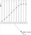
図12Aおよび図12Bは、受信信号に対して互いに異なる受信フォーカス方向に沿って整相加算処理を実施する態様を示したものである。図12Aは、超音波プローブ10の送受信面に対して垂直方向に受信フォーカス方向を設定した場合を示したものである。図12Aに示す反射点Rで生じた反射波が各圧電素子10aで受信されるタイミングが図中における各プロットで示されている。このように、反射点Rで生じた反射波の受信タイミングは、圧電素子10a毎に異なる。整相加算処理部18は、各圧電素子10aによって生成された各受信信号a1~a11における反射点Rに対応する各プロット上の信号値を合算したものを整相加算信号として生成する。受信フォーカス方向を超音波プローブ10の送受信面に対して垂直方向とする場合、反射点Rを超音波プローブ10の送受信面に対して垂直方向に移動させて各時刻における整相加算信号を生成する。
図12Bは、超音波プローブ10の送受信面に対して斜め方向に受信フォーカス方向を設定した場合を示したものである。図12Bに示す反射点Rで生じた反射波が各圧電素子10aで受信されるタイミングが図中において各プロットで示されている。整相加算処理部18は、各圧電素子10aによって生成された受信信号a1~a11における反射点Rに対応する各プロット上の信号値を合算したものを整相加算信号として生成する。受信フォーカス方向を超音波プローブ10の送受信面に対して斜め方向とする場合、反射点Rを超音波プローブ10の送受信面に対して斜め方向に移動させて各時刻における整相加算信号を生成する。図12Aおよび図12Bに示すように、受信フォーカス方向が異なると、受信信号a1~a11上における加算処理対象となる信号値の組み合わせが変化するので、生成される整相加算信号は異なるものとなる。
このように単一の受信信号に対して互いに異なる複数の方向の各々に沿って整相加算処理を行うことによって生成される複数の整相加算信号は、互いに異なる複数の方向に向けて順次送信された超音波の各送信に応じて生成された複数の受信信号の各々に対して整相加算処理を行うことによって生成される複数の整相加算信号と等価となる。すなわち、受信フォーカス方向をある方向に設定して整相加算処理を行うことは、当該方向に向けて反射された超音波の反射波を受信することに相当する。従って複数の受信フォーカスの方向の各々に沿って整相加算処理を行うことにより、当該複数の方向の各々に向けて反射された超音波の反射波を捉えることができる。そこで、本実施形態に係る超音波診断装置では、上記第1~第6の実施形態に係る描出処理における、互いに異なる複数の方向に超音波を送信して各送信に対応する複数のBモード画像を生成する処理に代えて、単一の方向にのみ超音波を送信し、これによって得られた受信信号に対して互いに異なる複数の受信フォーカス方向に沿って整相加算処理を行って、各受信フォーカス方向に対応する複数のBモード画像を生成する処理を含む描出処理を実行する。
図13は、本発明の第7の実施形態に係る描出処理プログラムにおける処理の流れを示すフローチャートである。なお、この描出処理プログラムが実行される前に、少なくとも1回の超音波の送受信が実施され、かかる超音波の送受信に応じて生成された受信信号が既に受信信号メモリ16aに格納されているものとする。
ステップS31において、整相加算処理部18は、受信信号メモリ16aから受信信号を読み出す。
ステップS32において、整相加算処理部18は、受信信号メモリ16aから読み出し受信信号に対して、予め定められた複数の受信フォーカス方向の各々に沿って整相加算処理を実施して、各受信フォーカス方向の各々に対応する複数の整相加算信号を生成する。ここでは、互いに異なる2つの受信フォーカス方向に沿って整相加算処理を実施するものとする。
ステップS33において、Bモード画像生成部22は、整相加算処理部18から供給される各受信フォーカス方向に対応する整相加算信号の各々に対して公知のフィルタリング処理、Log圧縮処理、包絡線検波処理、STC(Sensitivity Time Control)処理、補間処理及び走査変換処理などを施し、2つの受信フォーカス方向の各々に対応する2つのBモード画像の画像信号を生成する。
ステップS34において、抽出部24は、Bモード画像生成部22において生成された2つのBモード画像の各々から、当該2つのBモード画像における同一の反射点に対応する各画素の画素値を読み出す。
ステップS35において、抽出部24は、読み出した同一の反射点に対応する各画素の画素値の2つのBモード画像間における差分値Dを、同一の反射点に対応する各画素について導出する。
ステップS36において、抽出部24は、ステップS35において導出した差分値Dが所定の閾値以下となる画素を抽出する。すなわち、抽出部24は、互いに異なる2つの受信フォーカス方向の各々に対応する2つのBモード画像間で画素値の変化が比較的小さい画素を抽出する。この処理によって、乳腺構造M上の各反射点に対応する画素が排除される一方、微小石灰化部C上の各反射点に対応する画素が抽出される。
ステップS37において、Bモード画像生成部22は、先のステップS33おいて生成したBモード画像上に抽出部24が抽出した画素を明示するようにBモード画像を再構築する。例えば、Bモード画像生成部22は、抽出部24によって抽出された画素の輝度を、他の画素よりも十分に高くなるように画像信号を生成してもよい。または、Bモード画像生成部22は、抽出部24によって抽出された画素に、他の画素とは異なる色を割り当てて画像信号を生成してもよい。Bモード画像生成部22は、生成した画像信号をモニタ30に供給する。これにより、モニタ30には、微小石灰化部30の位置、大きさおよび範囲が明示されたBモード画像が表示される。
なお、本実施形態に係る描出処理プログラムにおけるステップS34を第2の実施形態に係る描出処理プログラムにおけるステップS14aに置き換えることも可能である。また、本実施形態に係る描出処理プログラムにおけるステップS35およびステップS36をそれぞれ、第3の実施形態に係る描出処理プログラムにおけるステップS15bおよびステップS16bに置き換えることも可能である。また、本実施形態に係る描出処理プログラムにおけるステップS34乃至ステップS37をそれぞれ、第4の実施形態に係る描出処理プログラムにおけるステップS14c乃至ステップS17cに置き換えることも可能である。また、本実施形態に係る描出処理プログラムにおけるステップS35およびステップS36をそれぞれ、第5の実施形態に係る描出処理プログラムにおけるステップS15dおよびステップS16dに置き換えることも可能である。また、本実施形態に係る描出処理プログラムにおけるステップS35乃至ステップS37を第6の実施形態に係るステップS15eおよびステップS16eに置き換えることも可能である。
また、上記の説明では、抽出部24によって抽出された画素を、モニタ30上に表示されたBモード画像上に重畳表示する場合を例示したが、抽出部24によって抽出された画素のみをその位置を明示するようにモニタ30上に表示してもよい。
また、受信信号に対して互いに異なる複数の受信フォーカス方向に沿って整相加算処理を行う場合に、ある受信フォーカス方向と他の受信フォーカス方向のなす角が90°となるような少なくとも2つの受信フォーカス方向が含まれていることが好ましい。これにより、乳腺構造M上の各反射点に対応する画素を効率的に排除することが可能となり、その結果、微小石灰化部Cの描出精度を向上させることが可能となる。
なお、上記の各実施形態では、乳房内に生じた微小石灰化部を描出する場合を例示したが、甲状腺や前立腺などの他の部位に生じた微小石灰化部を描出する場合にも本発明を適用することが可能である。また、微小石灰化部のみならず、超音波に対して拡散反射性を示すマイクロクリップ等の他の微小構造体を描出する場合にも本発明を適用することが可能である。
また、上記の各実施形態では、互いに異なる複数の送信方向または受信方向に対応して整相加算処理を実施して生成した整相加算信号に公知のフィルタリング処理、Log圧縮処理、包絡線検波処理、STC処理、補間処理及び走査変換処理などを施して生成したBモード画像において、同一の反射点に対応する各画素の画素値の比較解析を行って微小石灰化などの微小構造体を抽出する場合を例示したが、Bモード画像に限定されず、整相加算信号や、加算する前の整相した各チャンネルの受信信号などにおいて最大値や最小値またはその差分値など、信号の強度に相当する指標値を導出し、該指標値の比較解析を行って微小石灰化などの微小構造体を抽出してもよい。
また、上記の各実施形態において、互いに異なる複数の方向に超音波を送信する場合には、受信方向と送信方向が同じでもよいし、異なっていてもよい。
日本国特許出願2013-137379号の開示はその全体が参照により本明細書に取り込まれる。本明細書に記載された全ての文献、特許出願、および技術規格は、個々の文献、特許出願、および技術規格が参照により取り込まれることが具体的かつ個々に記された場合と同程度に、本明細書中に参照により取り込まれる。
Claims (14)
- 反射点から互いに異なる複数の方向に向けて反射された超音波の反射波に基づいて前記複数の方向の各々に対応する複数の画像を生成する画像生成手段と、
前記画像生成手段によって生成された前記複数の画像における同一の反射点に対応する各画素の画素値の比較解析を行って、画素値の近似する特定の画素を抽出する抽出手段と、
前記抽出手段によって抽出された前記特定の画素を表示する表示手段と、
を含む超音波診断装置。 - 前記抽出手段は、前記画像生成手段によって生成された前記複数の画像における同一の反射点に対応する各画素のうち、前記複数の画像間における画素値の差分値またはばらつきの大きさを示す指標値が所定の閾値以下となる画素を前記特定の画素として抽出する
請求項1に記載の超音波診断装置。 - 前記抽出手段は、前記画像生成手段によって生成された前記複数の画像における同一の反射点に対応する各画素のうち、前記複数の画像間における画素値の相関値が所定の閾値以上となる画素を前記特定の画素として抽出する
請求項1に記載の超音波診断装置。 - 前記抽出手段は、前記画像生成手段によって生成された前記複数の画像の各々において、所定の閾値以上の画素値を有する画素を前記特定の画素として抽出する
請求項2または3に記載の超音波診断装置。 - 前記抽出手段は、前記画像生成手段によって生成された前記複数の画像における同一の反射点に対応する各画素のうち、前記複数の画像間における最小の画素値が所定の閾値以上である画素を抽出する
請求項1に記載の超音波診断装置。 - 前記表示手段は、前記抽出手段によって抽出された画素のみを表示する
請求項1乃至5のいずれか1項に記載の超音波診断装置。 - 前記表示手段は、前記画像生成手段によって生成されたいずれかの画像上に前記抽出手段によって抽出された画素を視認可能に表示する
請求項1乃至5のいずれか1項に記載の超音波診断装置。 - 前記抽出手段は、前記画像生成手段によって生成された前記複数の画像における同一の反射点に対応する各画素うち、前記複数の画像間で最小の画素値を有する画素を抽出し、
前記表示手段は、前記抽出手段によって抽出された画素によって構成される画像を表示する
請求項1に記載の超音波診断装置。 - 前記画像生成手段は、互いに異なる複数の方向に向けて順次送信された超音波の各送信に応じて生成された複数の受信信号の各々に基づいて、前記複数の方向の各々に対応する複数の画像を生成する
請求項1乃至8のいずれか1項に記載の超音波診断装置。 - 超音波の送信に応じて生成された受信信号に対して互いに異なる複数の方向の各々に沿って整相加算処理を行って、前記複数の方向の各々に対応する複数の整相加算信号を生成する整相加算手段を更に含み、
前記画像生成手段は、前記整相加算手段によって生成された前記複数の整相加算信号の各々に基づいて、前記複数の方向の各々に対応する複数の画像を生成する
請求項1乃至8のいずれか1項に記載の超音波診断装置。 - 前記画像生成手段は、1の方向および前記1の方向に対して90°傾いた他の方向に向けて送信された超音波の各送信に対応する少なくとも2つの画像を生成する
請求項9に記載の超音波診断装置。 - 前記整相加算手段は、超音波の送信に応じて生成された受信信号に対して1の方向および前記1の方向に対して90°傾いた他の方向の各々に沿って整相加算処理を行って、前記1の方向および前記他の方向の各々に対応する少なくとも2つの整相加算信号を生成する
請求項10に記載の超音波診断装置。 - 反射点から互いに異なる複数の方向に向けて反射された超音波の反射波に基づいて前記複数の方向の各々に対応する複数の画像を生成することと、
前記生成された複数の画像における同一の反射点に対応する各画素の画素値の比較解析を行って、画素値の近似する特定の画素を抽出することと、
前記抽出された特定の画素を表示することと、
を含む画像描出方法。 - コンピュータを、
反射点から互いに異なる複数の方向に向けて反射された超音波の反射波に基づいて前記複数の方向の各々に対応する複数の画像を生成する画像生成手段と、
前記画像生成手段によって生成された前記複数の画像における同一の反射点に対応する各画素の画素値の比較解析を行って、画素値の近似する特定の画素を抽出する抽出手段と、
前記抽出手段によって抽出された前記特定の画素を表示する表示手段と、
として機能させるためのプログラム。
Applications Claiming Priority (2)
| Application Number | Priority Date | Filing Date | Title |
|---|---|---|---|
| JP2013137379A JP2015008942A (ja) | 2013-06-28 | 2013-06-28 | 超音波診断装置、画像描出方法およびプログラム |
| JP2013-137379 | 2013-06-28 |
Publications (1)
| Publication Number | Publication Date |
|---|---|
| WO2014208258A1 true WO2014208258A1 (ja) | 2014-12-31 |
Family
ID=52141610
Family Applications (1)
| Application Number | Title | Priority Date | Filing Date |
|---|---|---|---|
| PCT/JP2014/064176 Ceased WO2014208258A1 (ja) | 2013-06-28 | 2014-05-28 | 超音波診断装置、画像描出方法およびプログラム |
Country Status (2)
| Country | Link |
|---|---|
| JP (1) | JP2015008942A (ja) |
| WO (1) | WO2014208258A1 (ja) |
Citations (7)
| Publication number | Priority date | Publication date | Assignee | Title |
|---|---|---|---|---|
| JPH078492A (ja) * | 1993-06-28 | 1995-01-13 | Toshiba Corp | 超音波診断装置 |
| JP2007313114A (ja) * | 2006-05-26 | 2007-12-06 | Toshiba Corp | 超音波診断装置、超音波画像処理装置及び超音波画像処理プログラム |
| JP2010000143A (ja) * | 2008-06-18 | 2010-01-07 | Toshiba Corp | 超音波診断装置及びプログラム |
| JP2010029281A (ja) * | 2008-07-25 | 2010-02-12 | Aloka Co Ltd | 超音波診断装置 |
| JP2011125690A (ja) * | 2009-11-18 | 2011-06-30 | Toshiba Corp | 超音波診断装置、超音波画像処理装置及び超音波画像処理プログラム |
| JP2012071115A (ja) * | 2010-08-30 | 2012-04-12 | Toshiba Corp | 超音波診断装置 |
| JP2012213606A (ja) * | 2011-04-01 | 2012-11-08 | Toshiba Corp | 超音波診断装置及び制御プログラム |
-
2013
- 2013-06-28 JP JP2013137379A patent/JP2015008942A/ja active Pending
-
2014
- 2014-05-28 WO PCT/JP2014/064176 patent/WO2014208258A1/ja not_active Ceased
Patent Citations (7)
| Publication number | Priority date | Publication date | Assignee | Title |
|---|---|---|---|---|
| JPH078492A (ja) * | 1993-06-28 | 1995-01-13 | Toshiba Corp | 超音波診断装置 |
| JP2007313114A (ja) * | 2006-05-26 | 2007-12-06 | Toshiba Corp | 超音波診断装置、超音波画像処理装置及び超音波画像処理プログラム |
| JP2010000143A (ja) * | 2008-06-18 | 2010-01-07 | Toshiba Corp | 超音波診断装置及びプログラム |
| JP2010029281A (ja) * | 2008-07-25 | 2010-02-12 | Aloka Co Ltd | 超音波診断装置 |
| JP2011125690A (ja) * | 2009-11-18 | 2011-06-30 | Toshiba Corp | 超音波診断装置、超音波画像処理装置及び超音波画像処理プログラム |
| JP2012071115A (ja) * | 2010-08-30 | 2012-04-12 | Toshiba Corp | 超音波診断装置 |
| JP2012213606A (ja) * | 2011-04-01 | 2012-11-08 | Toshiba Corp | 超音波診断装置及び制御プログラム |
Also Published As
| Publication number | Publication date |
|---|---|
| JP2015008942A (ja) | 2015-01-19 |
Similar Documents
| Publication | Publication Date | Title |
|---|---|---|
| KR101386098B1 (ko) | 빔 프로파일에 기초하여 초음파 공간 합성 영상의 화질을 개선시키는 초음파 시스템 및 방법 | |
| JP6462340B2 (ja) | 超音波診断装置、画像処理装置及び画像処理方法 | |
| JP4575738B2 (ja) | 超音波画像境界抽出方法及び超音波画像境界抽出装置、並びに、超音波撮像装置 | |
| US20090099451A1 (en) | Ultrasonic imaging apparatus and a method for generating an ultrasonic image | |
| JP2008259605A (ja) | 超音波診断装置 | |
| JP5808325B2 (ja) | 超音波診断装置及び超音波診断装置の作動方法 | |
| US8206301B2 (en) | Ultrasonic imaging apparatus and ultrasonic image processing apparatus, method and program | |
| KR101188593B1 (ko) | 복수의 3차원 초음파 영상을 제공하는 초음파 시스템 및 방법 | |
| JP2008253549A (ja) | 超音波診断装置 | |
| CN108882914B (zh) | 超声造影成像方法及超声成像系统 | |
| KR20150117685A (ko) | 초음파 이미지 디스플레이 장치 및 초음파 이미지를 디스플레이하기 위한 방법 | |
| JP4575737B2 (ja) | 超音波撮像装置 | |
| JP7043193B2 (ja) | 解析装置、超音波診断装置、及び解析プログラム | |
| WO2013153857A1 (ja) | 超音波診断装置及び軌跡表示方法 | |
| JP2018086323A (ja) | 超音波診断装置 | |
| JP2020509862A (ja) | 臓器視認のための最適走査面選択 | |
| CN102626328B (zh) | 超声波诊断装置、超声波图像处理装置及取得方法 | |
| US8870777B2 (en) | Ultrasound diagnostic apparatus | |
| JP4314166B2 (ja) | 超音波診断装置 | |
| JPWO2012070588A1 (ja) | 超音波動画像処理方法、装置、およびプログラム | |
| JP2014161478A (ja) | 超音波診断装置及びその制御プログラム | |
| US10492762B2 (en) | Ultrasound diagnostic device, ultrasound diagnostic method, and program | |
| WO2014208258A1 (ja) | 超音波診断装置、画像描出方法およびプログラム | |
| KR20100053071A (ko) | 초음파 영상을 구현하는 초음파 영상 시스템 및 그 방법 | |
| JP4732086B2 (ja) | 超音波診断装置 |
Legal Events
| Date | Code | Title | Description |
|---|---|---|---|
| 121 | Ep: the epo has been informed by wipo that ep was designated in this application |
Ref document number: 14816868 Country of ref document: EP Kind code of ref document: A1 |
|
| NENP | Non-entry into the national phase |
Ref country code: DE |
|
| 122 | Ep: pct application non-entry in european phase |
Ref document number: 14816868 Country of ref document: EP Kind code of ref document: A1 |