WO2014207931A1 - Communication system and method - Google Patents
Communication system and method Download PDFInfo
- Publication number
- WO2014207931A1 WO2014207931A1 PCT/JP2013/067923 JP2013067923W WO2014207931A1 WO 2014207931 A1 WO2014207931 A1 WO 2014207931A1 JP 2013067923 W JP2013067923 W JP 2013067923W WO 2014207931 A1 WO2014207931 A1 WO 2014207931A1
- Authority
- WO
- WIPO (PCT)
- Prior art keywords
- information
- receiving
- port
- unit
- identification information
- Prior art date
Links
Images


Classifications
-
- H—ELECTRICITY
- H04—ELECTRIC COMMUNICATION TECHNIQUE
- H04N—PICTORIAL COMMUNICATION, e.g. TELEVISION
- H04N21/00—Selective content distribution, e.g. interactive television or video on demand [VOD]
- H04N21/40—Client devices specifically adapted for the reception of or interaction with content, e.g. set-top-box [STB]; Operations thereof
- H04N21/43—Processing of content or additional data, e.g. demultiplexing additional data from a digital video stream; Elementary client operations, e.g. monitoring of home network or synchronising decoder's clock; Client middleware
- H04N21/436—Interfacing a local distribution network, e.g. communicating with another STB or one or more peripheral devices inside the home
- H04N21/43615—Interfacing a Home Network, e.g. for connecting the client to a plurality of peripherals
-
- H—ELECTRICITY
- H04—ELECTRIC COMMUNICATION TECHNIQUE
- H04N—PICTORIAL COMMUNICATION, e.g. TELEVISION
- H04N21/00—Selective content distribution, e.g. interactive television or video on demand [VOD]
- H04N21/40—Client devices specifically adapted for the reception of or interaction with content, e.g. set-top-box [STB]; Operations thereof
- H04N21/41—Structure of client; Structure of client peripherals
- H04N21/4104—Peripherals receiving signals from specially adapted client devices
- H04N21/4108—Peripherals receiving signals from specially adapted client devices characterised by an identification number or address, e.g. local network address
Definitions
- Embodiments of the present invention relate to a communication system and method.
- MHL Mobile High-Definition Link
- a repeater device such as an amplifier can be connected between a portable device that is a source device and a television that is a sink device.
- a plurality of source devices can be connected to such a repeater device.
- RCP Remote Control Protocol
- the sink device transmits an RCP control command to the source device, and the source device executes the RCP command, thereby enabling remote operation between the devices.
- the MHL standard only defines that the sink device and the source device are connected at a ratio of 1: 1, and when the sink device and the source device are connected in a many-to-many manner with a repeater device interposed therebetween. Has a problem that a control command cannot be transmitted from the sink device to all of the plurality of source devices.
- the present invention has been made in view of the above, and enables transmission of a control command from a source device to a plurality of source devices even when the sink device and the source device are connected in a one-to-many manner. It is a main object of the present invention to provide a communication system and method capable of smoothly controlling the above.
- the communication system includes a transmission device that transmits a command, and a relay device that is connected between the transmission device and a plurality of reception devices that receive and execute the command.
- the relay device includes a first reception unit, a device list management unit, and a first transmission unit.
- the first receiving unit receives model information of each device from each of the plurality of receiving devices.
- the device list management unit includes, for each port identification information for identifying a port connecting each of the plurality of reception devices, device identification information for identifying the reception device and position information regarding the position of the relay device Device list information is generated.
- the first transmission unit transmits the device list information to the transmission device.
- the transmission device includes a second reception unit and a second transmission unit.
- the second transmission unit receives the device list information.
- the second transmission unit receives the command in which the port identification information corresponding to the device identification information of the receiving device to be accessed and the location information of the relay device are specified in the device list information. Send to.
- FIG. 1 is a configuration diagram of a communication system according to the first embodiment.
- FIG. 2 is a block diagram illustrating a functional configuration of the repeater device according to the first embodiment.
- FIG. 3 is a diagram illustrating an example of device list data according to the first embodiment.
- FIG. 4 is a block diagram illustrating a configuration of the digital television according to the first embodiment.
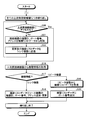
- FIG. 5 is a flowchart illustrating a communication processing procedure performed by the repeater device according to the first embodiment.
- FIG. 6 is a diagram illustrating an example of the MHL topology according to the first embodiment.
- FIG. 7 is a diagram illustrating an example of device list data according to the first embodiment.
- FIG. 8 is a diagram illustrating an example of device list data according to the first embodiment.
- FIG. 1 is a configuration diagram of a communication system according to the first embodiment.
- FIG. 2 is a block diagram illustrating a functional configuration of the repeater device according to the first embodiment.
- FIG. 3 is a diagram illustrating
- FIG. 9 is a diagram illustrating an example of device list data according to the first embodiment.
- FIG. 10 is a sequence diagram illustrating a communication processing procedure performed by the sink device and the repeater device according to the first embodiment.
- FIG. 11 is a diagram illustrating an example of a source device selection screen according to the first embodiment.
- FIG. 12 is a diagram illustrating an example in which a source device connected to a repeater device is disconnected.
- FIG. 13 is a flowchart illustrating a communication processing procedure performed by the repeater device according to the second embodiment.
- FIG. 14 is a sequence diagram illustrating a communication processing procedure between the repeater device and the sink device according to the second embodiment.
- the communication system of this embodiment has a configuration in which a plurality of portable devices 200a to 200n, a digital television 100, and a repeater device 400 are connected by an MHL cable 300.
- Video transmission via the repeater device 400 between the plurality of mobile devices 200a to 200n and the digital television 100 is realized in conformity with the MHL standard. More specifically, in the present embodiment, a plurality of portable devices 200a to 200n serve as source devices, and the digital television 100 serves as a sink device, and video data is transferred from the plurality of portable devices 200a to 200n via the repeater device 400. At 300, the data is transmitted to the digital television 100 using the protocol of the MHL standard.
- each of the plurality of portable devices 200a to 200n functions as a receiving device, and the digital television 100 functions as a transmitting device.
- the repeater device 400 functions as a relay device.
- the digital television 100 transmits an RCP command, which is a remote command, to the plurality of portable devices 200 via the repeater device 400, and the portable device 200 receives and executes the RCP command.
- the plurality of mobile devices 200a to 200n are collectively referred to as a plurality of mobile devices 200.
- a digital television 100 equipped with a digital broadcast receiving tuner will be described as an example of a communication device (transmission device).
- the present invention is not limited to the digital television 100, and may be a device such as a hard disk recorder or a set top box that includes a tuner that receives broadcast waves, processes video, and outputs it to an externally connected display device.
- a monitor that does not include a tuner and that receives video and audio from an external tuner may be used.
- the portable device 200 is exemplified as a receiving device, the present invention is not limited to this, and a device other than the portable device 200 may be used as the receiving device.
- the portable device 200 is the source device and the digital television 100 is the sink device, but this is also an example, and the present invention is not limited to this combination.
- the repeater device 400 of this embodiment corresponds to, for example, an amplifier, but is not limited to this.
- the repeater device 400 according to the present embodiment includes a communication unit 401, a determination unit 402, an address determination unit 403, a device list management unit 404, an input switching unit 407, and device list data 405. Management information 406 is mainly provided.
- each of a plurality of source devices (such as the portable terminal 200 in this embodiment) is connected to the port 408.
- a plurality of source devices (portable devices 200) side is referred to as an upstream side (upstream side), and a sink device (digital television 100) side is referred to as a downstream side (downstream side).
- 1 and 2 show a configuration in which the mobile device 200, that is, the source device is connected to the upstream side, but other repeater devices may be connected to the upstream side.
- 1 and 2 show a configuration in which the digital television 100, that is, a sink device is connected to the downstream side, but other repeater devices may be connected to the downstream side. Therefore, hereinafter, devices connected to the upstream side of the repeater device 400 are referred to as upstream-side connected devices including the mobile device 200, other source devices, and other repeater devices.
- Devices connected to the downstream side may be referred to as downstream-side connected devices including the digital TV 100 and other repeater devices.
- the management information 406 includes an address indicating the position of the repeater device 400 on the MHL topology and model information. As the model information, “repeater device” is set. Management information is stored in the capability register. However, the present invention is not limited to this, and the management information may be stored in a storage medium such as a memory.
- the model information is stored in each capability register of a source device such as the portable terminal 200 and a sink device such as the digital TV 100 with settings corresponding to each device.
- the model information of the source device such as the portable terminal 200 is set to “source device”, and the model information of the sink device such as the digital TV 100 is set to “sink device”.
- the communication unit 401 requests model information from a plurality of connected devices on the upstream side and a plurality of connected devices on the downstream side, and receives model information stored in the capability register of each connected device as a response.
- the communication unit 401 receives device list data described later from the connected device, that is, another repeater device. Receive.
- the communication unit 401 receives various RCP commands from the digital television 100 which is a sink device.
- the communication unit 401 transmits its device list data to the digital television 100.
- the communication unit 401 sends the RCP command from the port 408 of the port number to the source device (mobile phone) connected to the port. Terminal 200).
- the communication unit 401 functions as a first transmission unit and a first reception unit.
- the determination unit 402 determines whether the device information received from the downstream-side connected device by the communication unit 401 is “sink device” or “repeater device”. Further, the determination unit 402 determines whether the device information received from the upstream-side connected device by the communication unit 401 is a “source device” or a “repeater device”.
- the address determination unit 403 determines an address that is a position in its own MHL topology based on the device information received from the downstream-side connected device by the communication unit 401 and the device information received from the upstream-side connected device. .
- the address of each device is first determined by the sink device in the network of the sink device, repeater device, and source device, and then that address is used.
- the address is not first determined on the sink device side. Therefore, in this embodiment, the repeater device acquires the model information of the connected device and determines its own address based on the model information. The address is determined.
- the device list management unit 404 generates, updates, and manages the device list data 405.
- the device list data 405 is data indicating a list of connected devices on the upstream side of the repeater device 400. As shown in FIG. 3, the device list data 405 is registered in association with the address of the repeater device 400, the port number of the port to which the connected device is connected, and the connected device ID for identifying the connected device. The Here, the device list data 405 can search for a record registered using a port number as a key.
- the device list data 405 is stored in a storage medium such as a hard disk drive (HDD) or a memory.
- HDD hard disk drive
- the function list management unit 404 transmits the model information to the device list data 405. That is, the port number of the port connected to the mobile terminal 200, the connected device ID of the mobile terminal 200, and the address of the repeater device 400 are added in association with each other. If already registered, it is updated when there is a change.
- the function list management unit 404 determines that the model information acquired from the upstream-side connected device by the determining unit 402 is “repeater device”, and the communication unit 401 determines another repeater that is the connected device.
- the device list data in the other repeater device is received from the device, the port number of the port to which the other repeater device is connected and its own address are added in association with the received device list information.
- the input switching unit 407 activates the port number specified by the input switching command.
- the digital television 100 of this embodiment includes an antenna 2, a tuner 3 for receiving digital broadcasting, a signal processing unit 4, a video processing unit 5, a display processing unit 6, and a display unit. 7, audio processing unit 8, speaker 9, control unit 10, communication line 11, RAM 12 (Random Access Memory), ROM 13 (Read Only Memory), operation unit 14, light receiving unit 15, input An output control unit 16 and a communication unit 17 are mainly provided.
- the antenna 2 receives digital broadcasts such as BS, CS, and terrestrial waves.
- the tuner 3 selects a viewing channel designated by the user.
- the signal processing unit 4 extracts and processes the signal demodulated by the tuner 3 and the signal input from the input / output control unit 16 as various digital signals.
- the signal processing unit 4 separates the input signal into a video signal and an audio signal, and outputs the video signal to the video processing unit 5 and the audio signal to the audio processing unit 8.
- the video processing unit 5 performs processing for adjusting the video signal input from the signal processing unit 4 to the correct screen size, processing for removing noise included in the video signal, and the like as image quality processing for improving the image quality of the video.
- the display processing unit 6 performs processing for displaying the video signal output from the video processing unit 5 on the display unit 7. Further, the display processing unit 6 further superimposes OSD (On-Screen Display) display such as character information on the video signal output from the video processing unit 5.
- OSD On-Screen Display
- the display unit 7 displays the video signal on the screen. Then, the user views the television image by viewing the screen of the display unit 7.
- the audio processing unit 8 performs acoustic processing and amplifies the audio signal.
- the speaker 9 outputs an audio signal as audio. The user listens to the television sound by listening to the sound from the speaker 9.
- the control unit 10 controls each unit of the digital television 100.
- the control unit 10 is a processing unit capable of sequence processing.
- the control unit 10 outputs a control signal to each unit of the digital television 100 by developing the program stored in the ROM 13 in the RAM 12 and sequentially executing the program. Central control of movement.
- the communication line 11 connects the tuner 3, the signal processing unit 4, the video processing unit 5, the display processing unit 6, the audio processing unit 8, and the control unit 10 to each other, and the control unit 10, the tuner 3, and the signal processing unit 4. Data is exchanged among the video processing unit 5, the display processing unit 6, and the audio processing unit 8.
- the communication line 11 may be IIC-BUS or the like.
- the RAM 12 and ROM 13 store various data, and these data are exchanged with the control unit 10.
- the operation unit 14 is a switch that receives a user operation instruction.
- the light receiving unit 15 receives a signal transmitted from the remote controller 40 that has received a user operation instruction.
- the user can operate the digital television 100 and each device connected to the digital television 100 by operating various buttons and keys of the remote controller 40.
- the communication unit 17 has a function of communicating with a server connected via a network such as the Internet, requests information from the server, and receives information transmitted from the server.
- the input / output control unit 16 is connected to the repeater device 400 and transmits / receives data to / from the repeater device 400.
- the input / output control unit 16 functions as a second transmission unit and a second reception unit.
- the input / output control unit 16 transmits an RCP command to the repeater device 400.
- the input / output control unit 16 receives device list data managed by the repeater device 400 from the repeater device 400 as a response.
- the input / output control unit 16 includes the port number corresponding to the device ID of the portable device 200 or other sink device desired to be accessed by the user and the address of the repeater device 400 in the device list data. Then, various RCP commands are transmitted to the repeater device 400.
- the communication unit 401 acquires model information from the connected device on the downstream side (downstream side) (step S11). Then, the determination unit 402 determines the content of the model information of the downstream side connected device acquired in step S11 (step S12).
- step S12 sink device
- the address determination unit 403 recognizes that the sink device is the downstream end of the MHL topology, and the repeater device 400 It is determined that the position in the MHL topology is the position immediately before the downstream end, and an address indicating the position upstream of the downstream end is determined (step S13).
- the address determination unit 403 sets “1.0.0 as an address indicating a position upstream from the downstream end. .1 ".
- the address determination method is not limited to this.
- step S12 when it is determined in step S12 that the model information is “repeater device” (step S12: repeater device), the communication unit 401 reads from the capability register of the other repeater device that is the connected device. The address of another repeater device is acquired (step S14). Then, the address determination unit 403 determines the address of its own repeater device 400 from the addresses of other repeater devices (step S15).
- the address determination unit 403 determines an address indicating one upstream position from the acquired position of another repeater device. For example, in the example in which the address of another repeater device is “1.0.0.1”, the address determination unit 403 uses “1.0.0.1” as an address indicating a position one upstream side from the downstream end. 0.2 ". However, the address determination method is not limited to this.
- steps S16 to S20 is repeatedly executed for all the connected devices connected to the upstream side (upstream side) of the repeater device 400.
- step S16 the communication unit 401 acquires model information from the connected device on the upstream side (upstream side) (step S16). Then, the determination unit 402 determines the content of the model information of the upstream side connected device acquired in step S16 (step S17).
- the device list management unit 404 recognizes that the source device is the upstream terminal of the MHL topology, and repeater device 400.
- the position in the MHL topology is determined to be a position immediately before the downstream end, and the port number of the port 408 to which the connection device (portable device 200) as the source device is connected to the device list data 405,
- the device ID of the source device and the address of the repeater device 400 are associated with each other, and a new record is added or an existing record with the same port number is updated (step S18). If the device list data 405 itself does not exist, the device list management unit 404 generates the device list data and then performs the registration.
- FIG. 6 is a diagram illustrating an example of the MHL topology according to the first embodiment.
- a repeater device RPTA
- the source device SRC 1 is connected to the port of port number 10 of the repeater device (RPTA)
- the source device SRC2
- a repeater device RPTB
- the source device SRC10 is connected to the port of port number 50 of the repeater device (RPTB)
- the source device SRC20 is connected to the port of port number 60, respectively.
- the address of the repeater device (RPTA) is determined to be “1.0.0.1” and the address of the repeater device (RPTB) is determined to be “1.0.0.2”.
- the device list management unit 404 As a result of executing steps S17 and S18 in the repeater device (RPTA), the device list management unit 404 generates device list data shown in FIG. In the device list data 405 shown in FIG. 7, the source device (SRC1) is associated with the port number 10 and the source device (SRC2) is associated with the port number 20, together with the address of the repeater device (RPTA).
- step S ⁇ b> 17 repeater device
- the communication unit 401 receives the connection device, that is, another repeater device from the relevant device.
- Device list data stored in another repeater device is acquired (step S19).
- the device list management unit 404 adds the port number of the port connected to the other repeater device and the address of its own repeater device 400 in association with the device list data acquired in step S19 (step S20). .
- the device list management unit 404 will manage this device list data as its own device list data 405.
- the device list management unit 404 acquires the device list data of the other repeater devices acquired in step S19 and added or updated in step S20, and After own device list data 405 is merged, it is managed as own device list data 405.
- the repeater device (RPTB) is connected to the port of port number 30 of the repeater device (RPTA). It is assumed that the repeater device (RPTB) holds the device list data shown in FIG. As shown in FIG. 8, in the device list data of the repeater device (RPTB), the source device (SRC10) is associated with the port number 50 and the source device (SRC20) is associated with the port number 50 together with the address of the repeater device (RPTB). It has been.
- the communication unit 401 of the repeater device (RPTA) acquires the device list data illustrated in FIG. 8 from the repeater device (RPTB), and the device The list management unit 404 associates the device list data with the port number 30 of the port to which the repeater device (RPTB) is connected and the address “1.0.0.1” of its own repeater device (RPTA). to add. Then, the device list management unit 404 merges the device list data with the device list data shown in FIG. 7 already held in the repeater device (RPTA), and as a result, generates the device list data shown in FIG. To do.
- the input / output control unit 16 transmits a device list request command to the repeater device 400 (step S30).
- the communication unit 401 receives the device list request command, it transmits device list data 405 to the sink device as a response (step S31).
- the input / output control unit 16 receives the device list data 405, and the display processing unit 6 causes the user to select a desired source device to be accessed from the list of source devices registered in the device list data 405.
- a source device selection screen is displayed on the display unit 7. As shown in FIG. 11, a list of device IDs of source devices registered in the device list data 405 is displayed on the source device selection screen.
- the input / output control unit 16 of the digital television 100 receives the selection via the light receiving unit 15 (step S33). Then, the input / output control unit 16 transmits, to the repeater device 400, an input switching command specifying the port number corresponding to the device ID of the selected source device and the address of the repeater device in the device list data 405 (step S34). .
- the input switching unit 407 activates the port of the port number specified by the input switching command (step S35).
- the input / output control unit 16 of the digital television 100 transmits a desired RCP command to the repeater device 400 (step S36).
- the communication unit 401 when the communication unit 401 receives this RCP command, the received RCP command is transferred from the port activated in step S35 to the source device (mobile device 200) connected to the port ( Step S37). As described above, the digital television 100 can transmit the RCP command to a desired source device.
- the repeater device 400 acquires model information from each of the downstream-side connected device and all the upstream-side connected devices, determines its own address based on the model information, Device list data 405 that is a list of one or more connected devices on the downstream side is generated, and the device list data is transmitted to the digital television 100 that is a sink device. Then, the repeater device 400 activates the port having the port number designated by the sink device and transfers the RCP command received from the sink device from the activated port to the source device. For this reason, in the present embodiment, since the sink device can grasp and access all the source devices connected to the repeater device 400, the sink device can transmit one-to-many RCP commands from the source device. It becomes possible, and a plurality of source devices can be controlled smoothly.
- the repeater device determines its own address based on the model information of the connected device and includes this address.
- Device list data 405 is generated and transmitted to the sink device. For this reason, according to the present embodiment, on the sink device side, it is possible to easily grasp the repeater device and a plurality of source devices connected to the repeater device.
- the configurations of the repeater device 400 and the digital television 100 of the present embodiment are the same as those of the first embodiment.
- the device list data 405 of the present embodiment is the same as that of the first embodiment.
- the repeat device 400 detects and notifies the disconnection in the process of communication processing in which its own address is determined and the device list data 405 is registered.
- FIG. 13 is a flowchart illustrating a communication processing procedure performed by the repeater device according to the second embodiment. Since the processing up to step S50 is performed in the same manner as the processing from step S11 to S15 in the communication processing of the first embodiment, it is omitted in FIG.
- step S50 the communication unit 401 accesses the connected device on the upstream side (upstream side) and determines whether or not access is possible (step S50). If the access can be made (step S50: Yes), the process proceeds to step S16, and thereafter, the same processing as in the first embodiment is performed.
- step S50 when the communication unit 401 cannot access the connected device in step S50 (step S50: No), the device list management unit 404 displays the port number and repeater of the port to which the connected device that could not be connected is connected. A record including the address of the device 400 and the device ID of the connected device is deleted from the device list data 405 and updated (step S51).
- the communication unit 401 transmits the updated device list data 405 to the digital television 100 that is a sink device (step S52). If the device list data 405 has not yet been generated, the communication unit 401 displays the port number of the port connected to the connection device that could not be connected, the address of the repeater device 400, and the device ID of the connection device. It transmits to the digital television 100.
- the repeater device 400 may be configured to detect disconnection of the source device.
- FIG. 14 is a sequence diagram illustrating a communication processing procedure between the repeater device and the sink device according to the second embodiment.
- the processing from step S30 to S36 is the same as in the first embodiment.
- the communication unit 401 of the repeater device 400 receives the RPC command transmitted in step S36 and transmits the RCP command to the source device from the port having the port number specified by the RCP command (step S37), but the source device can be accessed. If not, the repeater device 400 determines that the source device is disconnected.
- the device list management unit 404 deletes the record including the port number of the port to which the source device that could not be connected, the address of the repeater device 400, and the device ID of the connected device is deleted from the device list data 405 and updated. (Step S61). Then, the communication unit 401 transmits the updated device list data 405 to the digital television 100 that is a sink device (step S62).
- the detection and the notification that the source device is disconnected are performed.
- the device can grasp the source device that is disconnected and cannot be accessed, the port number to which the source device is connected, and the address of the repeater device 400.
- the repeater device 400 deletes, from the device list data 405, a record including the port number of the port to which the source device that could not be connected, the address of the repeater device 400, and the device ID of the connected device.
- the updated device list data 405 is transmitted to the sink device. Regardless of the presence of the device list data 405, the port number of the port to which the connected device that could not be connected is connected, the address of the repeater device 400,
- the communication unit 401 may be configured to transmit the device ID of the connected device to the digital television 100.
- the present invention is not limited to the above-described embodiment as it is, and can be embodied by modifying the constituent elements without departing from the scope of the invention in the implementation stage.
- various inventions can be formed by appropriately combining a plurality of constituent elements disclosed in the embodiment. For example, some components may be deleted from all the components shown in the embodiment. Furthermore, the constituent elements over different embodiments may be appropriately combined.
Abstract
A communication system according to an embodiment of the invention comprises: a transmission apparatus and a relay apparatus connected between the transmission apparatus and each of a plurality of reception apparatuses. The relay apparatus comprises a first reception unit, a device list management unit and a first transmission unit. The first reception unit receives, from the plurality of reception apparatuses, the respective pieces of model information thereof. The device list management unit generates, for each of a plurality of pieces of port identification information for identifying the respective ones of ports to which the respective ones of the plurality of reception apparatuses are connected, a respective piece of device list information obtained by associating a respective piece of device identification information for identifying the respective one of the reception apparatuses with a piece of position information related to the position of the relay apparatus. The first transmission unit transmits the pieces of device list information to the transmission apparatus. The transmission apparatus transmits, to the relay apparatus, a command that designates the piece of port identification information corresponding, in the pieces of device list information, to the piece of device identification information of one of the reception apparatuses to be accessed and that also designates the piece of the position information of the relay apparatus.
Description
本発明の実施形態は、通信システムおよび方法に関する。
Embodiments of the present invention relate to a communication system and method.
近年、高精細な映像を表示可能なスマートフォン、タブレット等の携帯機器が普及してきており、このような携帯機器の高機能化に応えるべく、携帯機器とテレビジョン等の間の映像伝送技術として、例えば、MHL(Mobile High-Definition Link)等の規格が考案されている。このMHL規格においては、ソース機器である携帯機器と、シンク機器であるテレビジョンの間に、アンプ等のリピータ機器を接続することが可能である。このようなリピータ機器には、複数のソース機器の接続も可能となっている。
In recent years, mobile devices such as smartphones and tablets capable of displaying high-definition video have become widespread, and as a video transmission technology between mobile devices and televisions, etc. in order to respond to the higher functionality of such mobile devices, For example, standards such as MHL (Mobile High-Definition Link) have been devised. In the MHL standard, a repeater device such as an amplifier can be connected between a portable device that is a source device and a television that is a sink device. A plurality of source devices can be connected to such a repeater device.
また、MHL規格では、互いに接続された機器間での遠隔操作をリモートコマンドの送受信で実現可能にするためのRCP(Remote Control Protocol)が定義されている。シンク機器がRCPの制御コマンドをソース機器に送信し、ソース機器がRCPコマンドを実行することで、機器間での遠隔操作が可能となる。
In the MHL standard, RCP (Remote Control Protocol) is defined to enable remote operation between devices connected to each other by transmitting and receiving remote commands. The sink device transmits an RCP control command to the source device, and the source device executes the RCP command, thereby enabling remote operation between the devices.
しかしながら、MHL規格では、シンク機器とソース機器とが1:1で接続されることが定義されているだけであり、シンク機器とソース機器とをリピータ機器を介在させて多一対多で接続した場合には、シンク機器から、複数のソース機器の全てに制御コマンドを送信できないという問題がある。
However, the MHL standard only defines that the sink device and the source device are connected at a ratio of 1: 1, and when the sink device and the source device are connected in a many-to-many manner with a repeater device interposed therebetween. Has a problem that a control command cannot be transmitted from the sink device to all of the plurality of source devices.
本発明は、上記に鑑みてなされたものであって、シンク機器とソース機器とを一対多で接続した場合でも、ソース機器から複数のソース機器への制御コマンドの送信を可能とし、複数のソース機器を円滑に制御することが可能な通信システムおよび方法を提供することを主な目的とする。
The present invention has been made in view of the above, and enables transmission of a control command from a source device to a plurality of source devices even when the sink device and the source device are connected in a one-to-many manner. It is a main object of the present invention to provide a communication system and method capable of smoothly controlling the above.
実施の形態の通信システムは、コマンドを送信する送信装置と、前記送信装置と前記コマンドを受信して実行する複数の受信装置との間に接続された中継装置と、を備えた。前記中継装置は、第1受信部と、機器リスト管理部と、第1送信部とを備えている。前記第1受信部は、前記複数の受信装置のそれぞれから各装置の機種情報を受信する。前記機器リスト管理部は、前記複数の受信装置のそれぞれを接続するポートを識別するためのポート識別情報ごとに、前記受信装置を識別するための機器識別情報と、前記中継装置の位置に関する位置情報とを対応付けた機器リスト情報を生成する。前記第1送信部は、前記機器リスト情報を前記送信装置に送信する。前記送信装置は第2受信部と、第2送信部とを備えている。前記第2送信部は、前記機器リスト情報を受信する。前記第2送信部は、前記機器リスト情報において、アクセス対象の前記受信装置の前記機器識別情報に対応する前記ポート識別情報と、前記中継装置の位置情報とが指定された前記コマンドを前記中継装置に送信する。
The communication system according to the embodiment includes a transmission device that transmits a command, and a relay device that is connected between the transmission device and a plurality of reception devices that receive and execute the command. The relay device includes a first reception unit, a device list management unit, and a first transmission unit. The first receiving unit receives model information of each device from each of the plurality of receiving devices. The device list management unit includes, for each port identification information for identifying a port connecting each of the plurality of reception devices, device identification information for identifying the reception device and position information regarding the position of the relay device Device list information is generated. The first transmission unit transmits the device list information to the transmission device. The transmission device includes a second reception unit and a second transmission unit. The second transmission unit receives the device list information. The second transmission unit receives the command in which the port identification information corresponding to the device identification information of the receiving device to be accessed and the location information of the relay device are specified in the device list information. Send to.
以下、添付図面を参照して実施形態の通信システムおよび方法を詳細に説明する。本実施形態の通信システムは、図1に示すように、複数の携帯機器200a~200nとデジタルテレビ100と、リピータ機器400とがMHLケーブル300で接続された構成となっている。
Hereinafter, a communication system and method according to embodiments will be described in detail with reference to the accompanying drawings. As shown in FIG. 1, the communication system of this embodiment has a configuration in which a plurality of portable devices 200a to 200n, a digital television 100, and a repeater device 400 are connected by an MHL cable 300.
(実施形態1)
本実施形態では、複数の携帯機器200a~200nとデジタルテレビ100との間のリピータ機器400を介した映像伝送は、MHL規格に準拠して実現している。より具体的には、本実施形態では、複数の携帯機器200a~200nがソース機器、デジタルテレビ100がシンク機器となり、複数の携帯機器200a~200nから、リピータ機器400を介して映像データをMHLケーブル300でデジタルテレビ100にMHL規格のプロトコルで送信する。 (Embodiment 1)
In the present embodiment, video transmission via therepeater device 400 between the plurality of mobile devices 200a to 200n and the digital television 100 is realized in conformity with the MHL standard. More specifically, in the present embodiment, a plurality of portable devices 200a to 200n serve as source devices, and the digital television 100 serves as a sink device, and video data is transferred from the plurality of portable devices 200a to 200n via the repeater device 400. At 300, the data is transmitted to the digital television 100 using the protocol of the MHL standard.
本実施形態では、複数の携帯機器200a~200nとデジタルテレビ100との間のリピータ機器400を介した映像伝送は、MHL規格に準拠して実現している。より具体的には、本実施形態では、複数の携帯機器200a~200nがソース機器、デジタルテレビ100がシンク機器となり、複数の携帯機器200a~200nから、リピータ機器400を介して映像データをMHLケーブル300でデジタルテレビ100にMHL規格のプロトコルで送信する。 (Embodiment 1)
In the present embodiment, video transmission via the
そして、本実施の形態では、リモートコントローラ40のデジタルテレビ100に対する操作により、デジタルテレビ100から複数の携帯機器200a~200nを遠隔操作することが可能となっており、この遠隔操作をRCPコマンドで実現している。本実施の形態では、複数の携帯機器200a~200nのそれぞれが受信装置として機能し、デジタルテレビ100が送信装置として機能する。また、リピータ機器400が中継機器として機能する。デジタルテレビ100がリモートコマンドであるRCPコマンドをリピータ機器400を介して複数の携帯機器200に送信し、携帯機器200がRCPコマンドを受信して実行する。なお、これ以降、複数の携帯機器200a~200nを総称して、複数の携帯機器200と呼ぶ。
In this embodiment, it is possible to remotely control a plurality of portable devices 200a to 200n from the digital television 100 by operating the remote controller 40 on the digital television 100. This remote operation is realized by an RCP command. is doing. In the present embodiment, each of the plurality of portable devices 200a to 200n functions as a receiving device, and the digital television 100 functions as a transmitting device. Further, the repeater device 400 functions as a relay device. The digital television 100 transmits an RCP command, which is a remote command, to the plurality of portable devices 200 via the repeater device 400, and the portable device 200 receives and executes the RCP command. Hereinafter, the plurality of mobile devices 200a to 200n are collectively referred to as a plurality of mobile devices 200.
本実施形態では通信装置(送信装置)として、デジタル放送の受信用チューナを搭載するデジタルテレビ100を例にあげて説明する。ただし、デジタルテレビ100に限定されるものではなく、放送波を受信するチューナを備え、映像を処理して外部接続された表示装置に出力するハードディスクレコーダやセットトップボックス等の機器であってもよいし、あるいはチューナを備えず、外部チューナから映像や音声が入力されるモニター等であっても良い。また、送信装置として、デジタルテレビ100やハードディスクレコーダやセットトップボックス等の機器以外の機器を用いてもよい。
In the present embodiment, a digital television 100 equipped with a digital broadcast receiving tuner will be described as an example of a communication device (transmission device). However, the present invention is not limited to the digital television 100, and may be a device such as a hard disk recorder or a set top box that includes a tuner that receives broadcast waves, processes video, and outputs it to an externally connected display device. Alternatively, a monitor that does not include a tuner and that receives video and audio from an external tuner may be used. Moreover, you may use apparatuses other than apparatuses, such as the digital television 100, a hard-disk recorder, and a set top box, as a transmission apparatus.
また、受信装置として携帯機器200を例に挙げているが、これに限定されるものではなく、携帯機器200以外の装置を受信装置として用いてもよい。
In addition, although the portable device 200 is exemplified as a receiving device, the present invention is not limited to this, and a device other than the portable device 200 may be used as the receiving device.
さらに、本実施の形態では、携帯機器200をソース機器、デジタルテレビ100をシンク機器としているが、これも一例であり、この組み合わせに限定されるものではない。
Furthermore, in the present embodiment, the portable device 200 is the source device and the digital television 100 is the sink device, but this is also an example, and the present invention is not limited to this combination.
本実施形態のリピータ機器400は、例えば、アンプ等が該当するがこれに限定されるものではない。本実施形態のリピータ機器400は、図2に示すように、通信部401と、判断部402と、アドレス決定部403と、機器リスト管理部404と、入力切替え部407と、機器リストデータ405と、管理情報406とを主に備えている。リピータ機器400は、複数のソース機器(本実施形態では、携帯端末200等)のそれぞれがポート408に接続されている。ここで、リピータ機器400を中心にして、複数のソース機器(携帯機器200)側をアップストリーム側(上流側)といい、シンク装置(デジタルテレビ100)側をダウンストリーム側(下流側)という。
The repeater device 400 of this embodiment corresponds to, for example, an amplifier, but is not limited to this. As illustrated in FIG. 2, the repeater device 400 according to the present embodiment includes a communication unit 401, a determination unit 402, an address determination unit 403, a device list management unit 404, an input switching unit 407, and device list data 405. Management information 406 is mainly provided. In the repeater device 400, each of a plurality of source devices (such as the portable terminal 200 in this embodiment) is connected to the port 408. Here, with the repeater device 400 as a center, a plurality of source devices (portable devices 200) side is referred to as an upstream side (upstream side), and a sink device (digital television 100) side is referred to as a downstream side (downstream side).
図1、2では、アップストリーム側には携帯機器200、すなわちソース機器が接続されている構成を示しているが、アップストリーム側に他のリピータ機器が接続されている場合もある。また、図1、2では、ダウンストリーム側にはデジタルテレビ100、すなわち、シンク機器が接続されている構成を示しているが、ダウンストリーム側に他のリピータ機器が接続されている場合もある。このため、これ以降、リピータ機器400のアップストーム側に接続されている機器を、携帯機器200や他のソース機器、他のリピータ機器も含めてアップストリーム側の接続機器と呼び、リピータ機器400のダウンストーム側に接続されている機器をデジタルテレビ100や他のリピータ機器も含めてダウンストリーム側の接続機器と呼ぶ場合がある。
1 and 2 show a configuration in which the mobile device 200, that is, the source device is connected to the upstream side, but other repeater devices may be connected to the upstream side. 1 and 2 show a configuration in which the digital television 100, that is, a sink device is connected to the downstream side, but other repeater devices may be connected to the downstream side. Therefore, hereinafter, devices connected to the upstream side of the repeater device 400 are referred to as upstream-side connected devices including the mobile device 200, other source devices, and other repeater devices. Devices connected to the downstream side may be referred to as downstream-side connected devices including the digital TV 100 and other repeater devices.
管理情報406は、リピータ機器400のMHLトポロジ上の位置を示すアドレスと、機種情報とから構成される。機種情報としては、「リピータ機器」が設定されている。管理情報は、ケーパビリティレジスタに保存されている。ただし、これに限定されるものではなく、メモリ等の記憶媒体に管理情報を保存するように構成してもよい。
The management information 406 includes an address indicating the position of the repeater device 400 on the MHL topology and model information. As the model information, “repeater device” is set. Management information is stored in the capability register. However, the present invention is not limited to this, and the management information may be stored in a storage medium such as a memory.
ここで、機種情報は、リピータ機器400の他、携帯端末200等のソース機器、デジタルテレビ100等のシンク機器の各ケーパビリティレジスタにもそれぞれの機器に応じた設定で保存されている。携帯端末200等のソース機器の機種情報は「ソース機器」に設定され、デジタルテレビ100等のシンク機器の機種情報は「シンク機器」に設定されている。
Here, in addition to the repeater device 400, the model information is stored in each capability register of a source device such as the portable terminal 200 and a sink device such as the digital TV 100 with settings corresponding to each device. The model information of the source device such as the portable terminal 200 is set to “source device”, and the model information of the sink device such as the digital TV 100 is set to “sink device”.
通信部401は、アップストリーム側の接続機器とダウンストリーム側の複数の接続機器に機種情報を要求して、その応答として各接続機器のケーパビリティレジスタに保存されている機種情報を受信する。また、通信部401は、後述する判断部402により、アップストリーム側の接続機器から取得した機種情報が「リピータ機器」である場合に、当該接続機器、すなわち他のリピータ機器から後述する機器リストデータを受信する。
The communication unit 401 requests model information from a plurality of connected devices on the upstream side and a plurality of connected devices on the downstream side, and receives model information stored in the capability register of each connected device as a response. In addition, when the model information acquired from the upstream-side connected device is “repeater device” by the determination unit 402 described later, the communication unit 401 receives device list data described later from the connected device, that is, another repeater device. Receive.
また、通信部401は、シンク機器であるデジタルテレビ100から、各種RCPコマンドを受信する。通信部401は、受信したRCPコマンドが機器リスト要求コマンドである場合には、自己の機器リストデータを、デジタルテレビ100に送信する。また、通信部401は、受信したRCPコマンドに、ポート408を識別するためのポート番号の指定がある場合には、ポート番号のポート408からRCPコマンドを、当該ポートに接続されたソース機器(携帯端末200)に送信する。通信部401は、第1送信部、第1受信部として機能する。
Further, the communication unit 401 receives various RCP commands from the digital television 100 which is a sink device. When the received RCP command is a device list request command, the communication unit 401 transmits its device list data to the digital television 100. When the received RCP command includes a port number for identifying the port 408, the communication unit 401 sends the RCP command from the port 408 of the port number to the source device (mobile phone) connected to the port. Terminal 200). The communication unit 401 functions as a first transmission unit and a first reception unit.
判断部402は、通信部401によってダウンストリーム側の接続機器から受信した機器情報が「シンク機器」であるか、「リピータ機器」であるかを判断する。また、判断部402は、通信部401によってアップストリーム側の接続機器から受信した機器情報が「ソース機器」であるか、「リピータ機器」であるかを判断する。
The determination unit 402 determines whether the device information received from the downstream-side connected device by the communication unit 401 is “sink device” or “repeater device”. Further, the determination unit 402 determines whether the device information received from the upstream-side connected device by the communication unit 401 is a “source device” or a “repeater device”.
アドレス決定部403は、通信部401によってダウンストリーム側の接続機器から受信した機器情報、およびアップストリーム側の接続機器から受信した機器情報に基づいて、自身のMHLトポロジにおける位置であるアドレスを決定する。すなわち、HDMI(High-Definition Multimedia Interface)(登録商標)規格においては、シンク機器、リピータ機器、ソース機器のネットワークにおいて、シンク機器により最初に各機器のアドレスが決定され、その後はそのアドレスが使用される。これに対し、MHL規格では、HDMI規格とは異なり最初にシンク機器側でアドレスが決定されないため、本実施形態では、リピータ機器が接続機器の機種情報を取得して、機種情報に基づいて自己のアドレスを決定している。
The address determination unit 403 determines an address that is a position in its own MHL topology based on the device information received from the downstream-side connected device by the communication unit 401 and the device information received from the upstream-side connected device. . In other words, in the High-Definition Multimedia Interface (HDMI) standard, the address of each device is first determined by the sink device in the network of the sink device, repeater device, and source device, and then that address is used. The On the other hand, in the MHL standard, unlike the HDMI standard, the address is not first determined on the sink device side. Therefore, in this embodiment, the repeater device acquires the model information of the connected device and determines its own address based on the model information. The address is determined.
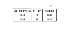
機器リスト管理部404は、機器リストデータ405を生成、更新、管理する。ここで、機器リストデータ405は、リピータ機器400のアップストリーム側の接続機器の一覧を示すデータである。図3に示すように、機器リストデータ405は、リピータ機器400のアドレスと、接続機器が接続されるポートのポート番号と、接続機器を識別するための接続機器IDとが対応付けられて登録される。ここで、機器リストデータ405は、ポート番号をキーとして登録されているレコードを検索可能となっている。機器リストデータ405は、ハードディスクドライブ装置(HDD)やメモリ等の記憶媒体に保存される。
The device list management unit 404 generates, updates, and manages the device list data 405. Here, the device list data 405 is data indicating a list of connected devices on the upstream side of the repeater device 400. As shown in FIG. 3, the device list data 405 is registered in association with the address of the repeater device 400, the port number of the port to which the connected device is connected, and the connected device ID for identifying the connected device. The Here, the device list data 405 can search for a record registered using a port number as a key. The device list data 405 is stored in a storage medium such as a hard disk drive (HDD) or a memory.
機能リスト管理部404は、判断部402によって、アップストリーム側の接続機器から取得した機種情報が「ソース機器」であると判断された場合に、機器リストデータ405に、機種情報を送信した接続機器、すなわち携帯端末200に接続されたポートのポート番号と、当該携帯端末200の接続機器IDと、リピータ機器400のアドレスとを対応付けて追加する。なお、既に登録されている場合には、変更がある場合に更新される。
When the determination unit 402 determines that the model information acquired from the connected device on the upstream side is the “source device”, the function list management unit 404 transmits the model information to the device list data 405. That is, the port number of the port connected to the mobile terminal 200, the connected device ID of the mobile terminal 200, and the address of the repeater device 400 are added in association with each other. If already registered, it is updated when there is a change.
また、機能リスト管理部404は、判断部402によってアップストリーム側の接続機器から取得した機種情報が「リピータ機器」であると判断された場合で、通信部401によって当該接続機器である他のリピータ機器から当該他のリピータ機器における機器リストデータを受信した場合に、受信した機器リスト情報に、他のリピータ機器を接続するポートのポート番号と、自己のアドレスとを対応付けて追加する。
The function list management unit 404 determines that the model information acquired from the upstream-side connected device by the determining unit 402 is “repeater device”, and the communication unit 401 determines another repeater that is the connected device. When the device list data in the other repeater device is received from the device, the port number of the port to which the other repeater device is connected and its own address are added in association with the received device list information.
入力切替え部407は、通信部401によってデジタルテレビ100から受信したRCPコマンドが入力切替えコマンドである場合には、入力切替えコマンドで指定されたポート番号をアクティブにする。
When the RCP command received from the digital television 100 by the communication unit 401 is an input switching command, the input switching unit 407 activates the port number specified by the input switching command.
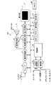
次に、本実施形態のデジタルテレビ100の詳細について説明する。図4に示すように、本実施形態のデジタルテレビ100は、アンテナ2と、デジタル放送の受信用のチューナ3と、信号処理部4と、映像処理部5と、表示処理部6と、表示部7と、音声処理部8と、スピーカー9と、制御部10と、通信ライン11と、RAM12(Random Access Memory)と、ROM13(Read Only Memory)と、操作部14と、受光部15と、入出力制御部16と、通信部17とを主に備えている。
Next, details of the digital television 100 of the present embodiment will be described. As shown in FIG. 4, the digital television 100 of this embodiment includes an antenna 2, a tuner 3 for receiving digital broadcasting, a signal processing unit 4, a video processing unit 5, a display processing unit 6, and a display unit. 7, audio processing unit 8, speaker 9, control unit 10, communication line 11, RAM 12 (Random Access Memory), ROM 13 (Read Only Memory), operation unit 14, light receiving unit 15, input An output control unit 16 and a communication unit 17 are mainly provided.
アンテナ2は、BS、CS、地上波等のデジタル放送を受信する。チューナ3は、ユーザが指示した視聴用のチャンネルを選局する。信号処理部4は、制御部10の制御のもと、チューナ3で復調された信号や入出力制御部16より入力された信号を様々なデジタル信号として取り出し処理する。また、信号処理部4では、入力された信号を映像信号と音声信号とに分離し、映像信号を映像処理部5へ、音声信号を音声処理部8へ出力する。
The antenna 2 receives digital broadcasts such as BS, CS, and terrestrial waves. The tuner 3 selects a viewing channel designated by the user. Under the control of the control unit 10, the signal processing unit 4 extracts and processes the signal demodulated by the tuner 3 and the signal input from the input / output control unit 16 as various digital signals. The signal processing unit 4 separates the input signal into a video signal and an audio signal, and outputs the video signal to the video processing unit 5 and the audio signal to the audio processing unit 8.
映像処理部5は、信号処理部4から入力した映像信号を正しい画面サイズに調整する処理や、映像についての画質を改善する画質処理として、映像信号に含まれるノイズを除去する処理等を行う。
The video processing unit 5 performs processing for adjusting the video signal input from the signal processing unit 4 to the correct screen size, processing for removing noise included in the video signal, and the like as image quality processing for improving the image quality of the video.
表示処理部6は、映像処理部5から出力される映像信号を表示部7に表示する処理を行う。また、表示処理部6は、映像処理部5から出力される映像信号に対して、さらに文字情報等のOSD(On-Screen Display)表示を重ねる。表示部7は、映像信号を画面に表示する。そして、ユーザは表示部7の画面を見ることにより、テレビ映像を見る。
The display processing unit 6 performs processing for displaying the video signal output from the video processing unit 5 on the display unit 7. Further, the display processing unit 6 further superimposes OSD (On-Screen Display) display such as character information on the video signal output from the video processing unit 5. The display unit 7 displays the video signal on the screen. Then, the user views the television image by viewing the screen of the display unit 7.
音声処理部8は、音声信号を音響処理するとともに増幅する。スピーカー9は、音声信号を音声として出力する。そして、ユーザはスピーカー9からの音声を聴くことにより、テレビ音声を聴く。
The audio processing unit 8 performs acoustic processing and amplifies the audio signal. The speaker 9 outputs an audio signal as audio. The user listens to the television sound by listening to the sound from the speaker 9.
制御部10は、デジタルテレビ100の各部を制御する。制御部10は、シーケンス処理が可能なプロセッシングユニットであり、ROM13に記憶されたプログラムをRAM12に展開して順次実行することで、デジタルテレビ100の各部に制御信号を出力して、デジタルテレビ100の動作を中央制御する。
The control unit 10 controls each unit of the digital television 100. The control unit 10 is a processing unit capable of sequence processing. The control unit 10 outputs a control signal to each unit of the digital television 100 by developing the program stored in the ROM 13 in the RAM 12 and sequentially executing the program. Central control of movement.
通信ライン11は、チューナ3、信号処理部4、映像処理部5、表示処理部6、音声処理部8、および、制御部10を互いに接続し、制御部10と、チューナ3、信号処理部4、映像処理部5、表示処理部6及び音声処理部8の間で、データの受け渡しを行う。通信ライン11は、具体的にはIIC-BUSなどであってよい。RAM12およびROM13は、様々なデータを記憶しており、制御部10との間で、これらのデータの受け渡しが行われる。
The communication line 11 connects the tuner 3, the signal processing unit 4, the video processing unit 5, the display processing unit 6, the audio processing unit 8, and the control unit 10 to each other, and the control unit 10, the tuner 3, and the signal processing unit 4. Data is exchanged among the video processing unit 5, the display processing unit 6, and the audio processing unit 8. Specifically, the communication line 11 may be IIC-BUS or the like. The RAM 12 and ROM 13 store various data, and these data are exchanged with the control unit 10.
操作部14は、ユーザの操作指示を受け付けるスイッチである。受光部15は、ユーザの操作指示を受け付けたリモートコントローラ40が発信する信号を受信する。ユーザは、リモートコントローラ40の各種ボタンやキーを操作することで、デジタルテレビ100及びデジタルテレビ100と接続する各機器を操作することができる。
The operation unit 14 is a switch that receives a user operation instruction. The light receiving unit 15 receives a signal transmitted from the remote controller 40 that has received a user operation instruction. The user can operate the digital television 100 and each device connected to the digital television 100 by operating various buttons and keys of the remote controller 40.
通信部17は、インターネット等のネットワークを介して接続されたサーバと通信する機能を有し、該サーバに対して情報を要求するとともに、サーバから送信された情報を受信する。
The communication unit 17 has a function of communicating with a server connected via a network such as the Internet, requests information from the server, and receives information transmitted from the server.
入出力制御部16は、リピータ機器400と接続され、リピータ機器400とのデータの送受信を行う。入出力制御部16は、第2送信部、第2受信部として機能する。入出力制御部16は、リピータ機器400に対してRCPコマンドを送信する。また、入出力制御部16は、RCPコマンドとして機器リスト要求コマンドをリピータ機器400に送信した場合に、その応答としてリピータ機器400から、リピータ機器400で管理している機器リストデータを受信する。
The input / output control unit 16 is connected to the repeater device 400 and transmits / receives data to / from the repeater device 400. The input / output control unit 16 functions as a second transmission unit and a second reception unit. The input / output control unit 16 transmits an RCP command to the repeater device 400. When the device list request command is transmitted to the repeater device 400 as an RCP command, the input / output control unit 16 receives device list data managed by the repeater device 400 from the repeater device 400 as a response.
また、入出力制御部16は、機器リストデータおいて、ユーザから選択されたアクセスを希望する携帯機器200や他のシンク機器の機器IDに対応するポート番号と、リピータ機器400のアドレスとを含めて、各種RCPコマンドをリピータ機器400に送信する。
In addition, the input / output control unit 16 includes the port number corresponding to the device ID of the portable device 200 or other sink device desired to be accessed by the user and the address of the repeater device 400 in the device list data. Then, various RCP commands are transmitted to the repeater device 400.
次に、以上のように構成された本実施形態の通信システムによる通信処理について説明する。まず、本実施形態のリピータ機器400による通信処理について図5を用いて説明する。この図5の処理は、一定時間ごとに実行される。
Next, communication processing by the communication system of the present embodiment configured as described above will be described. First, communication processing by the repeater device 400 according to the present embodiment will be described with reference to FIG. The processing of FIG. 5 is executed at regular time intervals.
まず、通信部401は、ダウンストリーム側(下流側)の接続機器から機種情報を取得する(ステップS11)。そして、判断部402は、ステップS11で取得したダウンストリーム側の接続機器の機種情報の内容を判断する(ステップS12)。
First, the communication unit 401 acquires model information from the connected device on the downstream side (downstream side) (step S11). Then, the determination unit 402 determines the content of the model information of the downstream side connected device acquired in step S11 (step S12).
機種情報が「シンク機器」であると判断された場合には(ステップS12:シンク機器)、アドレス決定部403は、シンク機器がMHLトポロジの下流側終端であると認識して、リピータ機器400のMHLトポロジにおける位置を、下流側終端の一つ手前の位置であると判断し、当該下流側終端の一つ上流側の位置を示すアドレスを決定する(ステップS13)。
When it is determined that the model information is “sink device” (step S12: sink device), the address determination unit 403 recognizes that the sink device is the downstream end of the MHL topology, and the repeater device 400 It is determined that the position in the MHL topology is the position immediately before the downstream end, and an address indicating the position upstream of the downstream end is determined (step S13).
例えば、下流側終端のアドレスを「1.0.0.0」とした例の場合、アドレス決定部403は、下流側終端から一つ上流側の位置を示すアドレスとして、「1.0.0.1」として決定することができる。ただし、アドレス決定の手法はこれに限定されるものではない。
For example, in the example in which the address at the downstream end is “1.0.0.0”, the address determination unit 403 sets “1.0.0 as an address indicating a position upstream from the downstream end. .1 ". However, the address determination method is not limited to this.
一方、ステップS12で、機種情報が「リピータ機器」であると判断された場合には(ステップS12:リピータ機器)、通信部401は、当該接続機器である他のリピータ機器のケーパビリティレジスタから、他のリピータ機器のアドレスを取得する(ステップS14)。そして、アドレス決定部403は、他のリピータ機器のアドレスから、自身のリピータ機器400のアドレスを決定する(ステップS15)。
On the other hand, when it is determined in step S12 that the model information is “repeater device” (step S12: repeater device), the communication unit 401 reads from the capability register of the other repeater device that is the connected device. The address of another repeater device is acquired (step S14). Then, the address determination unit 403 determines the address of its own repeater device 400 from the addresses of other repeater devices (step S15).
具体的には、アドレス決定部403は、取得した他のリピータ機器の位置から一つ上流側の位置を示すアドレスを決定する。例えば、他のリピータ機器のアドレスを「1.0.0.1」とした例の場合、アドレス決定部403は、下流側終端から一つ上流側の位置を示すアドレスとして、「1.0.0.2」として決定することができる。ただし、アドレス決定の手法はこれに限定されるものではない。
Specifically, the address determination unit 403 determines an address indicating one upstream position from the acquired position of another repeater device. For example, in the example in which the address of another repeater device is “1.0.0.1”, the address determination unit 403 uses “1.0.0.1” as an address indicating a position one upstream side from the downstream end. 0.2 ". However, the address determination method is not limited to this.
次に、ステップS16からS20までの処理を、リピータ機器400のアップストリーム側(上流側)に接続されている接続機器の全てについて繰り返し実行する。
Next, the processing from steps S16 to S20 is repeatedly executed for all the connected devices connected to the upstream side (upstream side) of the repeater device 400.
ステップS16では、通信部401は、アップストリーム側(上流側)の接続機器から機種情報を取得する(ステップS16)。そして、判断部402は、ステップS16で取得したアップストリーム側の接続機器の機種情報の内容を判断する(ステップS17)。
In step S16, the communication unit 401 acquires model information from the connected device on the upstream side (upstream side) (step S16). Then, the determination unit 402 determines the content of the model information of the upstream side connected device acquired in step S16 (step S17).
機種情報が「ソース機器」であると判断された場合には(ステップS17:ソース機器)、機器リスト管理部404は、ソース機器がMHLトポロジの上流側終端であると認識して、リピータ機器400のMHLトポロジにおける位置を、下流側終端の一つ手前の位置であると判断し、機器リストデータ405に、当該ソース機器である接続機器(携帯機器200)を接続するポート408のポート番号、当該ソース機器の機器ID、リピータ機器400のアドレスを対応付けて、新たなレコードとして追加または同一ポート番号の既存のレコードを更新する(ステップS18)。機器リストデータ405自体が存在しない場合には、機器リスト管理部404は、機器リストデータを生成した後、上記登録を行う。
When it is determined that the model information is “source device” (step S17: source device), the device list management unit 404 recognizes that the source device is the upstream terminal of the MHL topology, and repeater device 400. The position in the MHL topology is determined to be a position immediately before the downstream end, and the port number of the port 408 to which the connection device (portable device 200) as the source device is connected to the device list data 405, The device ID of the source device and the address of the repeater device 400 are associated with each other, and a new record is added or an existing record with the same port number is updated (step S18). If the device list data 405 itself does not exist, the device list management unit 404 generates the device list data and then performs the registration.
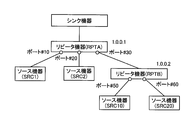
図6は、実施形態1のMHLトポロジの一例を示す図である。図6の例では、デジタルテレビ100等のシンク機器にリピータ機器(RPTA)が接続され、リピータ機器(RPTA)のポート番号10のポートにソース機器(SRC1)、ポート番号20のポートにソース機器(SRC2)、ポート番号30のポートにリピータ機器(RPTB)がそれぞれ接続されている。また、リピータ機器(RPTB)のポート番号50のポートにはソース機器(SRC10)、ポート番号60のポートにはソース機器(SRC20)がそれぞれ接続されている。また、リピータ機器(RPTA)のアドレスは「1.0.0.1」に、リピータ機器(RPTB)のアドレスは「1.0.0.2」にそれぞれ決定されたものとする。
FIG. 6 is a diagram illustrating an example of the MHL topology according to the first embodiment. In the example of FIG. 6, a repeater device (RPTA) is connected to a sink device such as the digital TV 100, the source device (SRC 1) is connected to the port of port number 10 of the repeater device (RPTA), and the source device ( SRC2), a repeater device (RPTB) is connected to the port of port number 30. Further, the source device (SRC10) is connected to the port of port number 50 of the repeater device (RPTB), and the source device (SRC20) is connected to the port of port number 60, respectively. It is assumed that the address of the repeater device (RPTA) is determined to be “1.0.0.1” and the address of the repeater device (RPTB) is determined to be “1.0.0.2”.
この例において、リピータ機器(RPTA)において、上記ステップS17、S18が実行された結果、機器リスト管理部404は、図7に示す機器リストデータを生成する。図7に示す機器リストデータ405には、リピータ機器(RPTA)のアドレスとともに、ポート番号10にソース機器(SRC1)、ポート番号20にソース機器(SRC2)が対応付けられている。
In this example, as a result of executing steps S17 and S18 in the repeater device (RPTA), the device list management unit 404 generates device list data shown in FIG. In the device list data 405 shown in FIG. 7, the source device (SRC1) is associated with the port number 10 and the source device (SRC2) is associated with the port number 20, together with the address of the repeater device (RPTA).
図5に戻り、ステップS17において、機種情報が「リピータ機器」であると判断された場合には(ステップS17:リピータ機器)、通信部401は、当該接続機器、すなわち他のリピータ機器から、当該他のリピータ機器に保存されている機器リストデータを取得する(ステップS19)。そして、機器リスト管理部404は、ステップS19で取得した機器リストデータに、他のリピータ機器を接続するポートのポート番号と、自己のリピータ機器400のアドレスとを対応付けて追加する(ステップS20)。今後、機器リスト管理部404は、この機器リストデータを、自己の機器リストデータ405として管理する。
Returning to FIG. 5, when it is determined that the model information is “repeater device” in step S <b> 17 (step S <b> 17: repeater device), the communication unit 401 receives the connection device, that is, another repeater device from the relevant device. Device list data stored in another repeater device is acquired (step S19). Then, the device list management unit 404 adds the port number of the port connected to the other repeater device and the address of its own repeater device 400 in association with the device list data acquired in step S19 (step S20). . In the future, the device list management unit 404 will manage this device list data as its own device list data 405.
なお、リピータ機器400が既に機器リストデータ405を保持している場合には、機器リスト管理部404は、ステップS19で取得し、ステップS20で追加または更新した他のリピータ機器の機器リストデータと、自己の機器リストデータ405をマージした上で、自己の機器リストデータ405として管理する。
If the repeater device 400 already holds the device list data 405, the device list management unit 404 acquires the device list data of the other repeater devices acquired in step S19 and added or updated in step S20, and After own device list data 405 is merged, it is managed as own device list data 405.
ここで、図6の例では、リピータ機器(RPTA)のポート番号30のポートにはリピータ機器(RPTB)が接続されている。リピータ機器(RPTB)が図8に示す機器リストデータを保持するものとする。リピータ機器(RPTB)の機器リストデータには、図8に示すように、リピータ機器(RPTB)のアドレスとともに、ポート番号50にソース機器(SRC10)、ポート番号60にソース機器(SRC20)が対応付けられている。
Here, in the example of FIG. 6, the repeater device (RPTB) is connected to the port of port number 30 of the repeater device (RPTA). It is assumed that the repeater device (RPTB) holds the device list data shown in FIG. As shown in FIG. 8, in the device list data of the repeater device (RPTB), the source device (SRC10) is associated with the port number 50 and the source device (SRC20) is associated with the port number 50 together with the address of the repeater device (RPTB). It has been.
そして、リピータ機器(RPTA)で上記ステップS17、S19、S20が実行されると、リピータ機器(RPTA)の通信部401は、リピータ機器(RPTB)から図8に示す機器リストデータを取得し、機器リスト管理部404は、当該機器リストデータに、リピータ機器(RPTB)を接続するポートのポート番号30と、自己のリピータ機器(RPTA)のアドレス「1.0.0.1」とを対応付けて追加する。そして、機器リスト管理部404は、この機器リストデータと、リピータ機器(RPTA)で既に保持している図7に示す機器リストデータとをマージし、その結果、図9に示す機器リストデータを生成する。
When the above steps S17, S19, and S20 are executed by the repeater device (RPTA), the communication unit 401 of the repeater device (RPTA) acquires the device list data illustrated in FIG. 8 from the repeater device (RPTB), and the device The list management unit 404 associates the device list data with the port number 30 of the port to which the repeater device (RPTB) is connected and the address “1.0.0.1” of its own repeater device (RPTA). to add. Then, the device list management unit 404 merges the device list data with the device list data shown in FIG. 7 already held in the repeater device (RPTA), and as a result, generates the device list data shown in FIG. To do.
上記ステップS16からS20までの処理がアップストリーム側のすべての接続機器について完了したら、処理を終了する。
When the processing from steps S16 to S20 is completed for all the connected devices on the upstream side, the processing ends.
次に、デジタルテレビ100等のシンク機器とリピータ機器400による携帯機器200等のソース機器に対するアクセスを実現する通信処理について図10を用いて説明する。
Next, communication processing for realizing access to the source device such as the portable device 200 by the sink device such as the digital television 100 and the repeater device 400 will be described with reference to FIG.
まず、デジタルテレビ100等のシンク機器では、入出力制御部16が機器リスト要求コマンドをリピータ機器400に送信する(ステップS30)。リピータ機器400では、通信部401が、機器リスト要求コマンドを受信すると、その応答として機器リストデータ405をシンク機器に送信する(ステップS31)。
First, in a sink device such as the digital TV 100, the input / output control unit 16 transmits a device list request command to the repeater device 400 (step S30). In the repeater device 400, when the communication unit 401 receives the device list request command, it transmits device list data 405 to the sink device as a response (step S31).
デジタルテレビ100では、入出力制御部16が機器リストデータ405を受信し、表示処理部6が、機器リストデータ405に登録されているソース機器の一覧からアクセスする所望のソース機器をユーザに選択させるためのソース機器選択画面を表示部7に表示する。図11に示すように、ソース機器選択画面には、機器リストデータ405に登録されたソース機器の機器IDの一覧が表示される。
In the digital television 100, the input / output control unit 16 receives the device list data 405, and the display processing unit 6 causes the user to select a desired source device to be accessed from the list of source devices registered in the device list data 405. A source device selection screen is displayed on the display unit 7. As shown in FIG. 11, a list of device IDs of source devices registered in the device list data 405 is displayed on the source device selection screen.
図10に戻り、ユーザはリモートコントローラ40でソース機器選択画面から所望のソース機器を選択すると、デジタルテレビ100の入出力制御部16は受光部15を介してかかる選択を受付ける(ステップS33)。そして、入出力制御部16は、機器リストデータ405において、選択されたソース機器の機器IDに対応するポート番号、リピータ機器のアドレスを指定した入力切替えコマンドをリピータ機器400に送信する(ステップS34)。
Referring back to FIG. 10, when the user selects a desired source device from the source device selection screen using the remote controller 40, the input / output control unit 16 of the digital television 100 receives the selection via the light receiving unit 15 (step S33). Then, the input / output control unit 16 transmits, to the repeater device 400, an input switching command specifying the port number corresponding to the device ID of the selected source device and the address of the repeater device in the device list data 405 (step S34). .
リピータ機器400では、通信部401がこの入力切替えコマンドを受信すると、入力切替え部407は、入力切替えコマンドで指定されたポート番号のポートをアクティブにする(ステップS35)。
In the repeater device 400, when the communication unit 401 receives this input switching command, the input switching unit 407 activates the port of the port number specified by the input switching command (step S35).
次に、デジタルテレビ100の入出力制御部16は、入力切替えコマンドで指定した、ポート番号およびリピータ機器400のアドレスを指定したら所望のRCPコマンドを、リピータ機器400に送信する(ステップS36)。
Next, when the port number and the address of the repeater device 400 designated by the input switching command are designated, the input / output control unit 16 of the digital television 100 transmits a desired RCP command to the repeater device 400 (step S36).
リピータ機器400では、通信部401がこのRCPコマンドを受信すると、ステップS35でアクティブにしたポートから、当該ポートに接続されたソース機器(携帯機器200)に対して、受信したRCPコマンドを転送する(ステップS37)。以上により、デジタルテレビ100は、所望のソース機器に対してRCPコマンドを送信することができる。
In the repeater device 400, when the communication unit 401 receives this RCP command, the received RCP command is transferred from the port activated in step S35 to the source device (mobile device 200) connected to the port ( Step S37). As described above, the digital television 100 can transmit the RCP command to a desired source device.
このように本実施形態では、リピータ機器400がダウンストリーム側の接続機器、アップストリーム側のすべての接続機器のそれぞれから機種情報を取得して、当該機種情報に基づいて自身のアドレスを決定し、ダウンストリーム側の一または複数の接続機器の一覧である機器リストデータ405を生成し、シンク機器であるデジタルテレビ100に機器リストデータを送信する。そして、リピータ機器400は、シンク機器で指定されたポート番号のポートをアクティブにしてシンク機器から受信したRCPコマンドをアクティブにしたポートからソース機器に転送する。このため、本実施形態では、シンク機器がリピータ機器400に接続されているすべてのソース機器を把握することができ、かつアクセス可能となるので、シンク機器からソース機器の一対多のRCPコマンドの送信が可能となり、複数のソース機器を円滑に制御することができる。
As described above, in this embodiment, the repeater device 400 acquires model information from each of the downstream-side connected device and all the upstream-side connected devices, determines its own address based on the model information, Device list data 405 that is a list of one or more connected devices on the downstream side is generated, and the device list data is transmitted to the digital television 100 that is a sink device. Then, the repeater device 400 activates the port having the port number designated by the sink device and transfers the RCP command received from the sink device from the activated port to the source device. For this reason, in the present embodiment, since the sink device can grasp and access all the source devices connected to the repeater device 400, the sink device can transmit one-to-many RCP commands from the source device. It becomes possible, and a plurality of source devices can be controlled smoothly.
特に、MHL規格では、HDMI規格とは異なり最初にシンク機器側でアドレスが決定されないため、本実施形態では、リピータ機器が接続機器の機種情報に基づいて自身のアドレスを決定し、このアドレスを含めて機器リストデータ405を生成してシンク機器に送信している。このため、本実施形態によれば、シンク機器側において、リピータ機器とリピータ機器に接続されている複数のソース機器を容易に把握することが可能となる。
In particular, in the MHL standard, unlike the HDMI standard, since the address is not first determined on the sink device side, in this embodiment, the repeater device determines its own address based on the model information of the connected device and includes this address. Device list data 405 is generated and transmitted to the sink device. For this reason, according to the present embodiment, on the sink device side, it is possible to easily grasp the repeater device and a plurality of source devices connected to the repeater device.
(実施形態2)
この実施形態2では、ソース機器がリピータ機器400と非接続になった場合に、その検知とソース機器が非接続になった旨の通知を行っている。例えば、図12に示すように、リピータ機器400のポート番号20のポートに接続されたソース機器(SRC2)が非接続になった場合、本実施形態のリピータ機器400は、これを検知して、ポート番号20、ソース機器の機器IDであるSRC2をシンク機器に通知する。 (Embodiment 2)
In the second embodiment, when the source device is disconnected from therepeater device 400, the detection and the notification that the source device is disconnected are performed. For example, as shown in FIG. 12, when the source device (SRC2) connected to the port of port number 20 of the repeater device 400 is disconnected, the repeater device 400 of the present embodiment detects this, The sink device is notified of the port number 20 and SRC2, which is the device ID of the source device.
この実施形態2では、ソース機器がリピータ機器400と非接続になった場合に、その検知とソース機器が非接続になった旨の通知を行っている。例えば、図12に示すように、リピータ機器400のポート番号20のポートに接続されたソース機器(SRC2)が非接続になった場合、本実施形態のリピータ機器400は、これを検知して、ポート番号20、ソース機器の機器IDであるSRC2をシンク機器に通知する。 (Embodiment 2)
In the second embodiment, when the source device is disconnected from the
本実施形態のリピータ機器400、デジタルテレビ100の構成は実施形態1と同様である。また、本実施形態の機器リストデータ405も実施形態1と同様である。
The configurations of the repeater device 400 and the digital television 100 of the present embodiment are the same as those of the first embodiment. The device list data 405 of the present embodiment is the same as that of the first embodiment.
本実施形態では、リピート機器400が自身のアドレスの決定および機器リストデータ405の登録を行う通信処理の過程で、非接続の検知と通知を行っている。図13は、実施形態2のリピータ機器による通信処理の手順を示すフローチャートである。ステップS50の前までの処理は実施形態1の通信処理におけるステップS11からS15までの処理と同様に行われるため、図13では省略している。
In the present embodiment, the repeat device 400 detects and notifies the disconnection in the process of communication processing in which its own address is determined and the device list data 405 is registered. FIG. 13 is a flowchart illustrating a communication processing procedure performed by the repeater device according to the second embodiment. Since the processing up to step S50 is performed in the same manner as the processing from step S11 to S15 in the communication processing of the first embodiment, it is omitted in FIG.
ステップS50では、通信部401は、アップストリーム側(上流側)の接続機器にアクセスを行って、アクセス可能か否かを判断する(ステップS50)。そして、アクセスできた場合には(ステップS50:Yes)、ステップS16へ移行し、その後は実施形態1と同様の処理が行われる。
In step S50, the communication unit 401 accesses the connected device on the upstream side (upstream side) and determines whether or not access is possible (step S50). If the access can be made (step S50: Yes), the process proceeds to step S16, and thereafter, the same processing as in the first embodiment is performed.
一方、ステップS50で通信部401が接続機器にアクセスできなかった場合には(ステップS50:No)、機器リスト管理部404は、接続できなかった接続機器を接続していたポートのポート番号、リピータ機器400のアドレス、当該接続機器の機器IDからなるレコードを機器リストデータ405から削除して更新する(ステップS51)。
On the other hand, when the communication unit 401 cannot access the connected device in step S50 (step S50: No), the device list management unit 404 displays the port number and repeater of the port to which the connected device that could not be connected is connected. A record including the address of the device 400 and the device ID of the connected device is deleted from the device list data 405 and updated (step S51).
そして、通信部401は、更新後の機器リストデータ405をシンク機器であるデジタルテレビ100に送信する(ステップS52)。まだ機器リストデータ405が生成される前である場合には、通信部401は、接続できなかった接続機器を接続していたポートのポート番号、リピータ機器400のアドレス、当該接続機器の機器IDをデジタルテレビ100に送信する。
Then, the communication unit 401 transmits the updated device list data 405 to the digital television 100 that is a sink device (step S52). If the device list data 405 has not yet been generated, the communication unit 401 displays the port number of the port connected to the connection device that could not be connected, the address of the repeater device 400, and the device ID of the connection device. It transmits to the digital television 100.
この他、シンク機器がソース機器にリピータ機器400を介してRCPコマンドを発行しようとした場合に、リピータ機器400がソース機器の非接続を検知するように構成してもよい。
In addition, when the sink device tries to issue an RCP command to the source device via the repeater device 400, the repeater device 400 may be configured to detect disconnection of the source device.
図14は、実施形態2のリピータ機器とシンク機器の通信処理の手順を示すシーケンス図である。ステップS30からS36までの処理は実施形態1と同様である。リピータ機器400の通信部401がステップS36で送信されたRPCコマンドを受信し、RCPコマンドで指定されたポート番号のポートからRCPコマンドをソース機器に送信したが(ステップS37)、ソース機器にアクセスできなかった場合、リピータ機器400はソース機器が非接続になったと判断する。
FIG. 14 is a sequence diagram illustrating a communication processing procedure between the repeater device and the sink device according to the second embodiment. The processing from step S30 to S36 is the same as in the first embodiment. The communication unit 401 of the repeater device 400 receives the RPC command transmitted in step S36 and transmits the RCP command to the source device from the port having the port number specified by the RCP command (step S37), but the source device can be accessed. If not, the repeater device 400 determines that the source device is disconnected.
そして、機器リスト管理部404は、接続できなかったソース機器を接続していたポートのポート番号、リピータ機器400のアドレス、当該接続機器の機器IDからなるレコードを機器リストデータ405から削除して更新する(ステップS61)。そして、通信部401は、更新後の機器リストデータ405をシンク機器であるデジタルテレビ100に送信する(ステップS62)。
Then, the device list management unit 404 deletes the record including the port number of the port to which the source device that could not be connected, the address of the repeater device 400, and the device ID of the connected device is deleted from the device list data 405 and updated. (Step S61). Then, the communication unit 401 transmits the updated device list data 405 to the digital television 100 that is a sink device (step S62).
このように本実施形態では、ソース機器がリピータ機器400と非接続になった場合に、その検知とソース機器が非接続になった旨の通知を行っているので、、デジタルテレビ100等のシンク機器は、非接続になってアクセスできなくなったソース機器と当該ソース機器が接続されたポート番号およびリピータ機器400のアドレスを把握することが可能となる。
As described above, in this embodiment, when the source device is disconnected from the repeater device 400, the detection and the notification that the source device is disconnected are performed. The device can grasp the source device that is disconnected and cannot be accessed, the port number to which the source device is connected, and the address of the repeater device 400.
なお、本実施形態のリピータ機器400は、接続できなかったソース機器を接続していたポートのポート番号、リピータ機器400のアドレス、当該接続機器の機器IDからなるレコードを機器リストデータ405から削除して更新後の機器リストデータ405をシンク機器に送信しているが、機器リストデータ405の有無にかかわらず、接続できなかった接続機器を接続していたポートのポート番号、リピータ機器400のアドレス、当該接続機器の機器IDをデジタルテレビ100に送信するように通信部401を構成してもよい。
Note that the repeater device 400 according to the present embodiment deletes, from the device list data 405, a record including the port number of the port to which the source device that could not be connected, the address of the repeater device 400, and the device ID of the connected device. The updated device list data 405 is transmitted to the sink device. Regardless of the presence of the device list data 405, the port number of the port to which the connected device that could not be connected is connected, the address of the repeater device 400, The communication unit 401 may be configured to transmit the device ID of the connected device to the digital television 100.
さらに、本実施形態では、映像伝送技術として、MHL規格およびRCPを用いた例をあげて説明しているが、これらのプロトコルに限定されるものではない。
Furthermore, in the present embodiment, an example using the MHL standard and RCP is described as a video transmission technique, but the present invention is not limited to these protocols.
なお、本発明は、上記実施形態そのままに限定されるものではなく、実施段階ではその要旨を逸脱しない範囲で構成要素を変形して具体化することができる。また、上記実施形態に開示されている複数の構成要素の適宜な組み合わせにより、種々の発明を形成することができる。例えば、実施形態に示される全構成要素からいくつかの構成要素を削除してもよい。さらに、異なる実施形態にわたる構成要素を適宜組み合わせても良い。
Note that the present invention is not limited to the above-described embodiment as it is, and can be embodied by modifying the constituent elements without departing from the scope of the invention in the implementation stage. Moreover, various inventions can be formed by appropriately combining a plurality of constituent elements disclosed in the embodiment. For example, some components may be deleted from all the components shown in the embodiment. Furthermore, the constituent elements over different embodiments may be appropriately combined.
Claims (10)
- コマンドを送信する送信装置と、前記送信装置と前記コマンドを受信して実行する複数の受信装置との間に接続された中継装置と、を備えた通信システムであって、
前記中継装置は、
前記複数の受信装置のそれぞれから各装置の機種情報を受信する第1受信部と、
前記複数の受信装置のそれぞれを接続するポートを識別するためのポート識別情報ごとに、前記受信装置を識別するための機器識別情報と、前記中継装置の位置に関する位置情報とを対応付けた機器リスト情報を生成する機器リスト管理部と、
前記機器リスト情報を前記送信装置に送信する第1送信部と、を備え、
前記送信装置は、
前記機器リスト情報を受信する第2受信部と、
前記機器リスト情報において、アクセス対象の前記受信装置の前記機器識別情報に対応する前記ポート識別情報と、前記中継装置の位置情報とが指定された前記コマンドを前記中継装置に送信する第2送信部と、
を備えた通信システム。 A communication system comprising: a transmission device that transmits a command; and a relay device that is connected between the transmission device and a plurality of reception devices that receive and execute the command,
The relay device is
A first receiving unit that receives model information of each device from each of the plurality of receiving devices;
A device list in which device identification information for identifying the receiving device is associated with position information regarding the position of the relay device for each port identification information for identifying a port connecting each of the plurality of receiving devices. A device list management unit for generating information;
A first transmission unit for transmitting the device list information to the transmission device,
The transmitter is
A second receiving unit for receiving the device list information;
A second transmission unit configured to transmit, to the relay device, the command in which the port identification information corresponding to the device identification information of the receiving device to be accessed and the location information of the relay device are specified in the device list information; When,
A communication system comprising: - 前記第1受信部は、前記コマンドを受信し、
前記中継装置は、
前記コマンドで指定された前記ポート識別情報の前記ポートをアクティブにする切替え部を、備え、
前記第1送信部は、アクティブにされた前記ポートから前記ポートに接続された前記受信装置に前記コマンドを送信する、
請求項1に記載の通信システム。 The first receiving unit receives the command,
The relay device is
A switching unit that activates the port of the port identification information specified by the command,
The first transmission unit transmits the command from the activated port to the receiving device connected to the port;
The communication system according to claim 1. - 前記第1受信部は、さらに、前記送信装置から前記機種情報を受信し、
前記中継装置は、
前記送信装置と前記複数の受信装置とからそれぞれ受信した機種情報に基づいて、前記中継装置のネットワーク上の位置を決定する決定部、
をさらに備えた請求項1に記載の通信システム。 The first receiving unit further receives the model information from the transmitting device,
The relay device is
A determination unit that determines a position of the relay device on the network based on model information received from the transmission device and the plurality of reception devices, respectively;
The communication system according to claim 1, further comprising: - 前記第1受信部は、前記複数の受信装置が含まれる上流側から前記機種情報を受信し、
前記中継装置は、
前記機種情報が、ソース機器を示すか、リピータ機器を示すかを判断する判断部をさらに備え、
前記機能リスト管理部は、前記機種情報が前記ソース機器を示す場合に、前記機器リストに、前記機種情報を送信した前記受信装置に接続されたポートのポート識別情報と、前記受信装置の前記機器識別情報と、前記中継装置の前記位置情報とを対応付けて追加する、
請求項1に記載の通信システム。 The first receiving unit receives the model information from an upstream side including the plurality of receiving devices,
The relay device is
A determination unit for determining whether the model information indicates a source device or a repeater device;
When the model information indicates the source device, the function list management unit includes, in the device list, port identification information of a port connected to the receiving device that has transmitted the model information, and the device of the receiving device. Adding identification information and the position information of the relay device in association with each other;
The communication system according to claim 1. - 前記第1受信部は、前記機種情報が前記リピータ機器を示す場合に、前記機種情報を送信した前記受信装置から機器リスト情報を取得し、
前記機能リスト管理部は、前記受信装置から取得した機器リスト情報に、前記機種情報を送信した前記受信装置に接続されたポートのポート識別情報と、前記中継装置の前記位置情報とを対応付けて追加する、
請求項4に記載の通信システム。 The first receiving unit obtains device list information from the receiving device that has transmitted the model information when the model information indicates the repeater device;
The function list management unit associates the device list information acquired from the receiving device with port identification information of a port connected to the receiving device that has transmitted the model information, and the position information of the relay device. to add,
The communication system according to claim 4. - 前記第1送信部は、さらに、前記受信装置が前記ポートと非接続になった場合に、非接続になった前記受信装置の前記機器識別情報と、前記非接続になった前記受信装置を接続していたポートの前記ポート識別情報とを、前記送信装置に送信する、
請求項2に記載の通信システム。 The first transmitting unit further connects the device identification information of the disconnected receiving device and the disconnected receiving device when the receiving device is disconnected from the port. Transmitting the port identification information of the port that has been to the transmitting device;
The communication system according to claim 2. - 前記機能リスト管理部は、さらに、前記受信装置が前記ポートと非接続になった場合に、非接続になった前記受信装置の前記機器識別情報と、前記非接続になった前記受信装置を接続していたポートの前記ポート識別情報とを前記機能リスト情報から削除することにより、前記機能リスト情報を更新し、
前記第1送信部は、更新された前記機能リスト情報を前記送信装置に送信する、
請求項6に記載の通信システム。 The function list management unit further connects the device identification information of the disconnected receiving device and the disconnected receiving device when the receiving device is disconnected from the port. The function list information is updated by deleting the port identification information of the port that has been used from the function list information,
The first transmission unit transmits the updated function list information to the transmission device;
The communication system according to claim 6. - 前記第1受信部は、前記機種情報を受信できなかった前記受信装置が、前記ポートと非接続になったと判断する、
請求項6に記載の通信システム。 The first receiving unit determines that the receiving device that has not received the model information is disconnected from the port;
The communication system according to claim 6. - 前記第1受信部は、前記コマンドを送信した前記受信装置が存在しない旨を受信した場合に、当該受信装置が前記ポートと非接続になったと判断する、
請求項6に記載の通信システム。 When the first receiving unit receives that the receiving device that has transmitted the command does not exist, the first receiving unit determines that the receiving device is disconnected from the port;
The communication system according to claim 6. - 送信装置によりコマンドを受信して実行する複数の受信装置のそれぞれから各装置の機種情報を受信し、
前記複数の受信装置のそれぞれを接続するポートを識別するためのポート識別情報ごとに、前記受信装置を識別するための機器識別情報と、前記中継装置の位置に関する位置情報とを対応付けた機器リスト情報を生成し、
前記機器リスト情報を前記送信装置に送信する、
通信方法。 Receive model information of each device from each of a plurality of receiving devices that receive and execute commands by the transmitting device,
A device list in which device identification information for identifying the receiving device is associated with position information regarding the position of the relay device for each port identification information for identifying a port connecting each of the plurality of receiving devices. Generate information,
Transmitting the device list information to the transmission device;
Communication method.
Priority Applications (2)
| Application Number | Priority Date | Filing Date | Title |
|---|---|---|---|
| PCT/JP2013/067923 WO2014207931A1 (en) | 2013-06-28 | 2013-06-28 | Communication system and method |
| JP2013541108A JPWO2014207931A1 (en) | 2013-06-28 | 2013-06-28 | COMMUNICATION SYSTEM, METHOD, AND RELAY DEVICE |
Applications Claiming Priority (1)
| Application Number | Priority Date | Filing Date | Title |
|---|---|---|---|
| PCT/JP2013/067923 WO2014207931A1 (en) | 2013-06-28 | 2013-06-28 | Communication system and method |
Publications (1)
| Publication Number | Publication Date |
|---|---|
| WO2014207931A1 true WO2014207931A1 (en) | 2014-12-31 |
Family
ID=52141322
Family Applications (1)
| Application Number | Title | Priority Date | Filing Date |
|---|---|---|---|
| PCT/JP2013/067923 WO2014207931A1 (en) | 2013-06-28 | 2013-06-28 | Communication system and method |
Country Status (2)
| Country | Link |
|---|---|
| JP (1) | JPWO2014207931A1 (en) |
| WO (1) | WO2014207931A1 (en) |
Citations (3)
| Publication number | Priority date | Publication date | Assignee | Title |
|---|---|---|---|---|
| JP2012138933A (en) * | 2012-02-21 | 2012-07-19 | Toshiba Corp | Communication system |
| JP2012204999A (en) * | 2011-03-24 | 2012-10-22 | Panasonic Corp | Relay system, relay device, and relay method |
| JP2013106117A (en) * | 2011-11-11 | 2013-05-30 | Onkyo Corp | Repeating device and program of the same |
-
2013
- 2013-06-28 WO PCT/JP2013/067923 patent/WO2014207931A1/en active Application Filing
- 2013-06-28 JP JP2013541108A patent/JPWO2014207931A1/en active Pending
Patent Citations (3)
| Publication number | Priority date | Publication date | Assignee | Title |
|---|---|---|---|---|
| JP2012204999A (en) * | 2011-03-24 | 2012-10-22 | Panasonic Corp | Relay system, relay device, and relay method |
| JP2013106117A (en) * | 2011-11-11 | 2013-05-30 | Onkyo Corp | Repeating device and program of the same |
| JP2012138933A (en) * | 2012-02-21 | 2012-07-19 | Toshiba Corp | Communication system |
Also Published As
| Publication number | Publication date |
|---|---|
| JPWO2014207931A1 (en) | 2017-02-23 |
Similar Documents
| Publication | Publication Date | Title |
|---|---|---|
| US8395706B2 (en) | Information processing system, display device, output device, information processing device, identification information acquisition method and identification information supply method | |
| US8711285B2 (en) | Output device, source apparatus, television set, system, output method, program, and recording medium | |
| KR102266194B1 (en) | Method and system for sharing output device between multimedia devices to send and receive data | |
| EP3096531A1 (en) | One-screen sharing method, apparatus, and system | |
| US20130057762A1 (en) | Source device, sink device, system, and recording medium | |
| US9357215B2 (en) | Audio output distribution | |
| KR20160019087A (en) | System, method and computer-readable medium for presenting media content | |
| WO2015139547A1 (en) | Method, device and system for setting up application scenario | |
| US20140052872A1 (en) | System and method for improved content streaming | |
| US20160205440A1 (en) | Information processing apparatus, television receiver, information processing method, program, and information processing system | |
| JP2009200788A (en) | Receiving device | |
| JP2013143581A (en) | Electronic device, terminal, program, and device operation control method | |
| US20140258464A1 (en) | System and method for electronic device control | |
| JP2014175736A (en) | Relay device and relay method | |
| JPWO2014155621A1 (en) | COMMUNICATION DEVICE, COMMUNICATION METHOD, AND PROGRAM | |
| KR20120038116A (en) | Electronic device, control device, and control method thereof | |
| WO2018096849A1 (en) | Information processing device, information processing method, and program | |
| KR101339835B1 (en) | Real time screen clone apparatus of mobile terminal, the system and method thereof | |
| WO2014207931A1 (en) | Communication system and method | |
| US20150019626A1 (en) | Server device, client machine, and content playback program | |
| JP6271169B2 (en) | Program related programs | |
| JP2015103237A (en) | Language information processing system | |
| JP5752550B2 (en) | Service providing system, terminal device, and control program | |
| JP2014036419A (en) | Electronic apparatus and broadcast signal transmitter | |
| CN105913626A (en) | Device for mirroring from source-end display screen to destination-end display screen |
Legal Events
| Date | Code | Title | Description |
|---|---|---|---|
| ENP | Entry into the national phase |
Ref document number: 2013541108 Country of ref document: JP Kind code of ref document: A |
|
| 121 | Ep: the epo has been informed by wipo that ep was designated in this application |
Ref document number: 13888203 Country of ref document: EP Kind code of ref document: A1 |
|
| NENP | Non-entry into the national phase |
Ref country code: DE |
|
| 122 | Ep: pct application non-entry in european phase |
Ref document number: 13888203 Country of ref document: EP Kind code of ref document: A1 |