WO2014203687A1 - Image processing method, image processing device, and image processing program - Google Patents
Image processing method, image processing device, and image processing program Download PDFInfo
- Publication number
- WO2014203687A1 WO2014203687A1 PCT/JP2014/063826 JP2014063826W WO2014203687A1 WO 2014203687 A1 WO2014203687 A1 WO 2014203687A1 JP 2014063826 W JP2014063826 W JP 2014063826W WO 2014203687 A1 WO2014203687 A1 WO 2014203687A1
- Authority
- WO
- WIPO (PCT)
- Prior art keywords
- image
- size
- image processing
- template
- calculation
- Prior art date
Links
Images


Classifications
-
- G—PHYSICS
- G06—COMPUTING; CALCULATING OR COUNTING
- G06T—IMAGE DATA PROCESSING OR GENERATION, IN GENERAL
- G06T7/00—Image analysis
- G06T7/0002—Inspection of images, e.g. flaw detection
- G06T7/0004—Industrial image inspection
- G06T7/001—Industrial image inspection using an image reference approach
-
- G—PHYSICS
- G06—COMPUTING; CALCULATING OR COUNTING
- G06V—IMAGE OR VIDEO RECOGNITION OR UNDERSTANDING
- G06V10/00—Arrangements for image or video recognition or understanding
- G06V10/20—Image preprocessing
- G06V10/25—Determination of region of interest [ROI] or a volume of interest [VOI]
-
- G—PHYSICS
- G06—COMPUTING; CALCULATING OR COUNTING
- G06V—IMAGE OR VIDEO RECOGNITION OR UNDERSTANDING
- G06V10/00—Arrangements for image or video recognition or understanding
- G06V10/40—Extraction of image or video features
- G06V10/42—Global feature extraction by analysis of the whole pattern, e.g. using frequency domain transformations or autocorrelation
- G06V10/431—Frequency domain transformation; Autocorrelation
-
- G—PHYSICS
- G06—COMPUTING; CALCULATING OR COUNTING
- G06T—IMAGE DATA PROCESSING OR GENERATION, IN GENERAL
- G06T2207/00—Indexing scheme for image analysis or image enhancement
- G06T2207/30—Subject of image; Context of image processing
- G06T2207/30108—Industrial image inspection
Definitions
- the present disclosure relates to an image processing method, an image processing apparatus, and an image processing program that perform a matching process using a template.
- FA Vectory Automation
- Template matching is a technique for searching an input image for an area that matches a pre-registered template.
- an image obtained by photographing a reference workpiece is used as a template.
- An image processing apparatus in the FA field performs template matching using the template and an input image obtained by photographing an inspection object such as a workpiece. Thereby, it is possible to automatically inspect the workpiece for defects.
- Patent Document 1 Japanese Patent Laid-Open No. 2000-3444
- Patent Document 1 states, “By devising a method for calculating a correlation coefficient with a small amount of calculation, it is not limited by the spatial frequency of a pattern, and high-speed processing
- an area of a predetermined value (specifically 0) is added to the observation image and the reference image, and the vertical and horizontal sizes of the image are set to the second floor.
- a technique of “inverse Fourier transforming the product (cross power spectrum) of the Fourier transform results of the observed image and the reference image by performing pre-processing as a raised pixel” is disclosed ([summary]).
- a Fourier transform such as Fast Fourier Transform (FFT) can be processed at high speed when an image having a factorial size of 2 is used.
- FFT Fast Fourier Transform
- a predetermined width is added (padding) to an observation image and a reference image used for template matching in order to improve the processing speed of template matching, and the vertical and horizontal size of the image is set to a second floor.
- the vertical and horizontal size of the image is set to a second floor.
- the computation time may increase conversely.
- This disclosure has been made to solve the above-described problems, and an object in one aspect is to perform template matching based on an image size that reduces the amount of calculation of template matching. It is providing the method, apparatus, and program which speed up.
- an image processing method for performing a matching process using a template accepts an area setting for a registered image obtained by imaging a target object serving as a reference, and has an image size within a predetermined range based on the size of the received area. From among them, determining an image size for which the amount of calculation of matching processing associated with the image size in advance is relatively small, and generating a template from a registered image based on information on the determined image size area Including.
- the determining includes determining an image size that minimizes an amount of calculation of the matching process from image sizes in a predetermined range based on the size of the received region.
- the determining includes determining an image size having a vertical width smaller than the vertical width of the size of the received area.
- the determining includes determining an image size having a width smaller than the width of the received area size.
- the center of the determined image size region coincides with the center of the received region.
- the generation is performed so that the degree of variation of the region on the registered image sandwiched between the outer frame having the same size as the determined image size and the inner frame inside the outer frame is relatively small. Generating a template from the registered image.
- the determination is based on the known calculation amount respectively associated with the image size in a predetermined range based on the image size. Including estimating a calculation amount corresponding to the image size.
- the calculation amount is an actually calculated calculation time for all or part of the matching process.
- the calculation amount is determined based on the image size and the calculation amount of the matching process.
- the matching process includes a process of detecting the position of the inspection object from an input image obtained by imaging the inspection object. The amount of calculation is determined based on the time taken to detect the position.
- the amount of calculation is determined based on the time required for Fourier transform in the matching process.
- the image processing method further includes updating a calculation amount associated with the image size in advance.
- an image processing apparatus that performs a matching process using a template.
- the image processing apparatus includes a reception unit for receiving a region setting for a registered image obtained by imaging a target object serving as a reference, and a predetermined range based on the size of the received region. From among the image sizes, a determination unit for determining an image size for which the amount of calculation of matching processing associated with the image size in advance is relatively small, and a template based on information on the determined image size area And a generating unit for generating from a registered image.
- the image processing apparatus further includes a storage unit for storing a table that defines the relationship between the image size and the calculation amount of the matching process.
- the determination unit is configured to determine an image size with which the calculation amount of the matching process is relatively reduced with reference to the table.
- a program for causing a computer to execute matching processing using a template accepts a setting of a region for a registered image obtained by imaging a target object serving as a reference, and an image size within a predetermined range based on the size of the received region.
- a template size is generated from the registered image based on information on the area of the determined image size, and determining an image size for which the amount of calculation of matching processing associated with the image size in advance is relatively small And execute.
- the template matching process can be speeded up by performing the matching process based on the image size that relatively reduces the amount of calculation of the matching process.
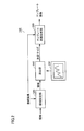
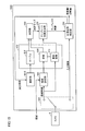
- FIG. 1 is a schematic diagram illustrating an overall configuration of an image processing system. It is a block diagram which shows an example of a function structure of an image processing apparatus. It is a figure which shows the relationship between the image size and the amount of calculation of template matching. It is a block diagram which shows an example of the hardware constitutions of an image processing apparatus. It is a block diagram which shows an example of a function structure of the image processing apparatus according to 1st Embodiment. It is a figure showing the setting area
- FIG. 1 is a schematic diagram showing an overall configuration of an image processing system 1 including an image processing apparatus 100 according to the present embodiment.
- the image processing system 1 optically inspects whether there is a defect or dirt on an inspection object (hereinafter also referred to as “work”), for example. More specifically, the image processing system 1 performs template matching with an image acquired by photographing the workpiece 2 using a template that is incorporated in a production line or the like and registered in advance.
- the image processing system 1 includes a camera 8, a manufacturing device 12, a transport mechanism 14, a display device 16, a mouse 18, and an image processing device 100.
- the manufacturing apparatus 12 is an apparatus for manufacturing the workpiece 2.
- the workpiece 2 is a mechanical part such as a circuit board.
- the workpiece 2 is transferred by a transfer mechanism 14 such as a belt conveyor.
- the conveyed work 2 is photographed by the camera 8 at a predetermined timing.
- An image obtained by the camera 8 is transmitted to the image processing apparatus 100.
- the image processing apparatus 100 has a registration mode for performing template registration processing and an inspection mode for executing inspection on the workpiece 2.
- the user can alternately switch between the inspection mode and the registration mode using an input device such as the mouse 18.
- the image processing apparatus 100 creates a template image from an image (hereinafter, also referred to as “registered image”) obtained by photographing the target workpiece 2 serving as a reference.
- the image processing apparatus 100 performs template matching using an image (hereinafter, also referred to as “input image”) obtained by imaging an inspection target such as the workpiece 2 and a template image. Thereby, the image processing system 1 automatically inspects the workpiece 2 for defects and the like.
- FIG. 2 is a block diagram illustrating an example of a functional configuration of the image processing apparatus 100. An outline of a functional configuration of the image processing apparatus 100 will be described with reference to FIG.
- the image processing apparatus 100 includes calculation amount information 230, an area setting unit 520, a determination unit 540, and a template image generation unit 550.
- the area setting unit 520 receives an area setting for the registered image. For example, the user sets an area for the registered image displayed on the display device 16 by using an input device such as the mouse 18.
- the region setting unit 520 outputs the region set by the user for the registered image (hereinafter also referred to as “setting region”) to the determination unit 540. Details of the setting area will be described later.
- the determination unit 540 has an image size (hereinafter, referred to as “image size”) in which a calculation amount of a template matching process associated in advance with an image size is relatively reduced from image sizes in a predetermined range based on the size of the setting region. (Also called “determined size”). For example, the calculation amount of the template matching process associated in advance with the image size is defined in the calculation amount information 230. The determination unit 540 determines the image size from the setting area and the calculation amount information 230 and outputs the image size to the template image generation unit 550.
- image size an image size in which a calculation amount of a template matching process associated in advance with an image size is relatively reduced from image sizes in a predetermined range based on the size of the setting region.
- the calculation amount information 230 is defined as a table representing the calculation amount relationship between the image size and the template matching. Details of the table will be described later. Further, the calculation amount information 230 may be defined as an approximate expression that represents the relationship between the calculation amount of the image size and the template matching. Details of the approximate expression will be described later.
- the template image generation unit 550 generates a template image from the registered image 413 based on the information on the image size area determined by the determination unit 540. Typically, the template image generation unit 550 cuts out a template image from the registered image 413 with the image size determined by the determination unit 540.
- the image processing apparatus 100 performs template matching using the template image and the input image.
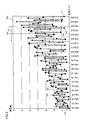
- FIG. 3 is a diagram showing the relationship between the image size and the amount of calculation for template matching. An overview of processing in the image processing apparatus 100 will be described with reference to FIG.
- the vertical axis (computation amount) of the computation amount information 230 represents the computation amount of all or part of the template matching process.
- the calculation amount is represented as an actually calculated calculation time for all or part of the template matching process.
- the horizontal axis (image size) of the calculation amount information 230 represents the vertical and horizontal sizes of an image used for template matching processing. As shown in FIG. 3, the amount of calculation for template matching does not increase in proportion to the vertical and horizontal sizes of the image.
- the calculation amount of template matching at the point 101 is about 4.2.
- the calculation amount of template matching at the point 102 having a larger image size than the point 101 is about 2.1. In this way, the amount of calculation may decrease despite the increase in the image size used for template matching.
- the calculation amount is about 0.8.
- the calculation amount is about 1.4. In this way, the amount of computation may increase by padding the vertical and horizontal sizes and factoring to 2.
- the image processing apparatus 100 determines an appropriate image size that reduces the calculation amount of the template matching, and registers the template image based on the information on the area of the image size. Generate from.
- the determination unit 540 has an image in which the calculation amount of the template matching process associated in advance with the image size is relatively reduced from the image size in a predetermined range based on the setting area. The size is determined with reference to the calculation amount information 230.
- the determination unit 540 calculates the relative amount of calculation of the template matching process from the image size of the predetermined range 121 with the point 120 as a reference.
- the image size to be reduced is determined.
- the determination unit 540 determines 224 ⁇ 224 (point 124) having the smallest calculation amount as the size of the template image.
- the template image generation unit 550 generates a template image having a size of 224 ⁇ 224 (point 124) by cutting it from the registered image.
- the determination unit 540 determines the point 125 having the next smallest calculation amount after the point 124 as the template image. The size may be determined.
- the image processing apparatus 100 may determine an image size smaller than the size of the set area, or may determine an image size larger than the size of the set area.
- the image processing apparatus 100 performs template matching using a template image and an input image having an image size with a relatively small amount of calculation, thereby reducing the amount of calculation of the template matching process and speeding up the template matching process. It becomes possible.
- FIG. 4 is a block diagram illustrating an example of a hardware configuration of the image processing apparatus 100. A hardware configuration of the image processing apparatus 100 will be described with reference to FIG.
- the image processing apparatus 100 is mainly mounted on a computer having a general-purpose architecture.
- the image processing apparatus 100 includes, as main components, a CPU (Central Processing Unit) 401, a RAM (Random Access Memory) 402, a ROM (Read Only Memory) 403, a network interface (I / F) 404, and a camera interface ( I / F) 405, a memory card interface (I / F) 407, and an auxiliary storage device 410.
- the camera 8, the display device 16, and the input device 440 are connected to the image processing device 100.
- Each component is communicably connected to each other via a bus 400.
- the CPU 401 controls the entire image processing apparatus 100 by executing various programs such as an operating system (OS) and an image processing program stored in the ROM 403, the auxiliary storage device 410, and the like.
- OS operating system
- image processing program stored in the ROM 403, the auxiliary storage device 410, and the like.
- the RAM 402 functions as a working memory for executing a program by the CPU 401, and temporarily stores various data necessary for executing the program.
- the ROM 403 stores an initial program (boot program) that is executed when the image processing apparatus 100 is started up.
- the network I / F 404 exchanges data with other devices (such as server devices) via various communication media. More specifically, the network I / F 404 is connected via a wired line such as Ethernet (registered trademark) (LAN (Local Area Network), WAN (Wide Area Network), etc.) and / or a wireless line such as a wireless LAN. Data communication.
- a wired line such as Ethernet (registered trademark) (LAN (Local Area Network), WAN (Wide Area Network), etc.) and / or a wireless line such as a wireless LAN. Data communication.
- the camera I / F 405 mediates data communication between the CPU 401 and the camera 8.
- the camera I / F 405 includes an image buffer and temporarily stores data of a registered image and an input image transmitted from the camera 8.
- the camera I / F 405 transfers the accumulated data to the auxiliary storage device 410 or the ROM 403.
- the camera I / F 405 gives an imaging command to the camera 8 in accordance with an internal command generated by the CPU 401.
- the memory card I / F 407 reads / writes data from / to various memory cards (nonvolatile storage media) 330 such as an SD (Secure Digital) card and a CF (Compact Flash (registered trademark)) card.
- various memory cards nonvolatile storage media
- SD Secure Digital
- CF Compact Flash
- the memory card I / F 407 is loaded with a memory card 430 storing an input image acquired by some device, and the input image read from the memory card 430 is stored in the auxiliary storage device 410.
- the auxiliary storage device 410 typically includes a large-capacity magnetic storage medium such as a hard disk.
- the auxiliary storage device 410 stores an image processing program 411 for realizing various types according to the present embodiment, an input image 412, a registered image 413, and a table 414. Further, the auxiliary storage device 410 may store a program such as an operating system. Details of the table 414 will be described later.
- the main body of the image processing apparatus 100 does not have to have a function of capturing a workpiece, acquires an input image and a registered image using a mechanism similar to a digital camera, and uses these images to the image processing apparatus 100 by an arbitrary method. You may make it input. More specifically, these images are input to the image processing apparatus 100 via the network I / F 404 and the memory card I / F 407.
- the image processing program 411 stored in the auxiliary storage device 410 is stored in a storage medium such as a CD-ROM (Compact Disk-Read Only Memory) or distributed, or distributed from a server device or the like via a network.
- the image processing program 411 may implement processing by calling necessary modules among program modules provided as part of an operating system executed by the image processing apparatus 100 at a predetermined timing and order. In this case, the image processing program 411 itself does not include a module provided by the operating system, and image processing is realized in cooperation with the operating system.
- the image processing program 411 may be provided by being incorporated in a part of some program instead of a single program. Even in such a case, the image processing program 411 itself does not include a module that is commonly used in the program, and image processing is realized in cooperation with the program. Even such an image processing program 411 that does not include some modules does not depart from the spirit of the image processing apparatus 100 according to the present embodiment. Furthermore, some or all of the functions provided by the image processing program 411 may be realized by dedicated hardware.
- the image processing apparatus 100 may not perform processing in real time.
- the image processing apparatus 100 may be in the form of a so-called cloud service in which at least one server apparatus realizes processing according to the present embodiment.
- the user transmits the input image 412 and the registered image 413 to the server device (cloud side) using his / her terminal.
- the apparatus side performs image processing according to the present embodiment on the transmitted input image 412 and registered image 413.
- the display device 16 displays a GUI (Graphical User Interface) screen provided by the operating system, an image generated by executing the image processing program 411, and the like.
- GUI Graphic User Interface
- the input device 440 typically includes a keyboard, a mouse, a touch panel, and the like.
- the input device 440 outputs the content of the instruction received from the user to the CPU 401 or the like.
- FIG. 5 is a block diagram showing an example of a functional configuration of the image processing apparatus 100 according to the first embodiment. The functional configuration of the image processing apparatus 100 will be described with reference to FIG.
- the image processing apparatus 100 includes an auxiliary storage device 410, an area setting unit 520, a determination unit 540, a template image generation unit 550, and a position / orientation detection unit 560.
- the auxiliary storage device 410 includes a registered image 413, a table 414, and an area 536 associated with the registered image 413.
- the image processing apparatus 100 has, as operation modes, a registration mode for performing template registration processing and an inspection mode for executing inspection on the workpiece 2.
- the user can switch between the registration mode and the inspection mode with the input device 440.
- the inspection mode can be switched, the switch 500 is switched.
- the registration mode is executed offline and the inspection mode is executed online.
- the registration mode and the inspection mode will be described.
- the camera 8 When the operation mode of the image processing apparatus 100 is the registration mode, the camera 8 outputs a registered image obtained by photographing a work to the auxiliary storage device 410 and the area setting unit 520.
- the area setting unit 520 receives an area setting for the registered image. For example, the user sets an area for the registered image displayed on the display device 16 using an input device such as the mouse 18. Details of the area setting will be described later.
- the area setting unit 520 stores the area 536 (setting area) set for the registered image by the user in the auxiliary storage device 410 in association with the registered image.
- a table 414 in which the image size and the amount of calculation for template matching are associated is stored in the auxiliary storage device 410. Details of the table 414 will be described later.
- the image processing apparatus 100 performs template matching when the operation mode is the inspection mode.
- the determination unit 540 relatively reduces the amount of calculation of the template matching process associated with the image size in advance from the image size in a predetermined range based on the size of the setting area.
- the determined size is output to the template image generation unit 550.
- the template image generation unit 550 generates a template image from the registered image 413 based on the information on the image size area determined by the determination unit 540. Typically, the template image generation unit 550 cuts out a template image from the registered image 413 with the image size determined by the determination unit 540. The template image generation unit 550 outputs the template image to the position / orientation detection unit 560.
- the template image generation unit 550 cuts out the template image so that the center of the template image matches the center of the setting area.
- the setting area set by the user is highly likely to be set around the registration object. Therefore, by matching the center of the setting area and the center of the template image, there is a high possibility of leaving a necessary part in which the registration target object is shown.
- the template image generation unit 550 may generate one template image by performing statistical processing such as averaging a plurality of images.
- the camera 8 outputs an input image obtained when the camera 8 images the workpiece 2 to be inspected to the position / orientation detection unit 560.
- the position / orientation detection unit 560 performs template matching using the input image output from the camera 8 and the template image output from the template image generation unit 550.
- the position / orientation detection unit 560 performs template matching using a rotation invariant phase only correlation (RIPOC).
- RIPOC rotation invariant phase only correlation
- the position / orientation detection unit 560 searches the input image for a region that matches the template, and outputs a movement amount and a rotation amount of the workpiece 2 included in the input image with respect to the workpiece 2 included in the registered image. Details of the RIPOC process will be described later.
- the template matching method is not limited to RIPOC.
- the position / orientation detection unit 560 may use any of a phase-only correlation method (POC: Phase Only Correlation), a matching process using Fourier Merin transform, and the like as a template matching method.
- POC Phase Only Correlation
- a matching process using Fourier Merin transform and the like as a template matching method.
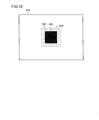
- FIG. 6 is a diagram illustrating a setting area on a registered image. Details of the setting area will be described with reference to FIG.
- the registration object 601 such as the workpiece 2 is shown in the registration image 413.
- the region setting unit 520 accepts region settings for the registered image 413.
- the user sets an area by enclosing the registration object 601 while confirming the registration image 413 displayed on the display device 16.
- the user surrounds the registration object 601 with a square such as a region 536.
- the shape of the region 536 is not limited to a quadrangle. For example, it may be any one of a circle, an ellipse, a polygon, and other shapes.
- the area 536 set by the user is stored in the auxiliary storage device 410 in association with the registered image 413.
- the area 536 is stored as coordinate values in the registered image 413.
- FIG. 7 is a diagram illustrating the data structure of the table 414. The data structure of the table 414 will be described with reference to FIG.
- the relationship between the image size and the amount of calculation for template matching is defined.
- the table 414 is configured as a two-dimensional table that defines the vertical and horizontal sizes of images and the amount of calculation for template matching.
- the table 414 defines template matching calculation amounts corresponding to the horizontal widths 701 to 707 of the image and the vertical widths 710 to 716 of the image.
- the calculation amount for an image having a horizontal width of 126 pixels (horizontal width 702) and a vertical width of 126 pixels (vertical width 711) is 3.
- the amount of calculation for an image having a horizontal width of 128 pixels (horizontal width 704) and a vertical width of 126 pixels (vertical width 711) is two.
- the amount of calculation is an index of the calculation time required for template matching.
- the calculation time is measured by actually performing template matching on a plurality of sizes of images on a predetermined personal computer.
- the image processing apparatus 100 stores the size of each image and the indexed calculation time for template matching for each image as a table 414.
- calculation time does not have to be the entire calculation time of the template matching process, and may be a part of the calculation time of the template matching process.
- the calculation time is defined as the time required for RIPOC in template matching to detect the position of the inspection object from the input image.
- the calculation amount may be an index based on the Fourier transform in RIPOC.
- a two-dimensional discrete Fourier transform can be realized by applying a one-dimensional DFT in two stages.
- the table 414 can be configured as a one-dimensional table storing an indexed execution time of the one-dimensional DFT. For example, when performing DFT on an M ⁇ N size image, the amount of computation is output as the sum of the amount of computation of a one-dimensional DFT of size M and the amount of computation of a one-dimensional DFT of size N.
- the amount of calculation may be defined by an approximate expression instead of a table.
- the calculation amount may be calculated from the image size and the calculation amount.
- a theoretical formula is used. It is generally known that a one-dimensional DFT of size N can be calculated with a calculation amount of O (N ⁇ ni) by using a Cooley-Turky algorithm. For this reason, O (N ⁇ ni) (ni is each prime number when N is primed) may be defined as the calculation amount of the one-dimensional DFT.
- the determination unit 540 determines an image size (determined size) at which the amount of calculation of the template matching process is relatively small from the image sizes in a predetermined range in the table 414 based on the size of the setting area.
- the determining unit 540 refers to a predetermined range 730 in the table 414 with the size 720 (128 ⁇ 128) as a reference, and determines an image size that minimizes the amount of calculation. Since the image size with the smallest calculation amount in the range 730 is the size 740 (128 ⁇ 126), the determination unit 540 determines the size 740 (128 ⁇ 126) as the determined size. The determined size is output to the template image generation unit 550.
- the size of a predetermined range in the table 414 referred to by the determination unit 540 is set when the image processing apparatus 100 is designed.
- the size of the range may be configured to be changed by the user.
- the size of the range is configured to be changeable in pixel units for each of the vertical width and the horizontal width.
- the image size defined in the table 414 need not be an integer, but may be a positive number.
- the determination unit 540 may determine an image size having a vertical width smaller than the vertical width of the setting area with reference to a range in the table 414 smaller than the vertical width of the setting area. Similarly, the determination unit 540 may determine an image size having a width smaller than the width of the setting area with reference to a range in the table 414 smaller than the width of the setting area. Thereby, the template matching process can be further accelerated.
- FIG. 8 is a block diagram illustrating an example of a functional configuration of the position / orientation detection unit 560. With reference to FIG. 8, RIPOC, which is an example of template matching processing, will be described.
- the RIPOC is executed by the position / orientation detection unit 560.
- the RIPOC calculates how much the inspection object shown in the input image is rotated with respect to the template image.
- the RIPOC is a process for correcting the rotation amount of the template image, and a process for calculating how much similarity and parallel movement amount exist between the correction template acquired by the rotation amount correction and the input image. Including.
- the position / orientation detection unit 560 includes a Fourier transform unit 810, a Fourier transform unit 820, a logarithmic processing unit 812, a logarithmic processing unit 822, a polar coordinate transform unit 814, and a polar coordinate transform unit 824. , A first POC processing unit 830, a rotation amount correction unit 840, and a second POC processing unit 850.
- the Fourier transform unit 810 calculates frequency information (amplitude component and phase component) included in the template image.
- the Fourier transform unit 820 sets a search range around the position where the detection target in the input image is likely to exist, and cuts out a template part corresponding to the search range from the input image. Typically, the size of the region to be cut out is the same size as the template image. Further, the Fourier transform unit 820 calculates frequency information (amplitude component and phase component) included in the cut out region. In the RIPOC process, the phase component is not necessarily required and may not be calculated.
- the logarithmic processing unit 812 and the polar coordinate conversion unit 814 logarithmize the amplitude component of the template image and convert it to polar coordinates.
- the logarithmic processing unit 822 and the polar coordinate conversion unit 824 logarithmize the amplitude component of the input image and convert it to polar coordinates.
- the rotation amount is expressed as a coordinate point on two-dimensional coordinates.
- the first POC processing unit 830 calculates a similarity and a parallel movement amount (corresponding to a rotation amount) for the result of the polar coordinate conversion output from the polar coordinate conversion unit 814 and the polar coordinate conversion unit 824, respectively.
- the template image and the input image are sequentially shifted, and the correlation value is calculated between the components of the spatial frequency included in each, thereby obtaining the highest similarity (POC peak value).
- the first POC processing unit 830 specifies the position where the similarity is the highest among the results of the polar coordinate conversion, and outputs the corresponding rotation amount to the rotation amount correction unit 840.
- the rotation amount correction unit 840 corrects the rotation of the template image according to the rotation amount calculated by the first POC processing unit 830. That is, the first POC processing unit 830 generates a correction template by rotationally correcting the template image.
- a method of rotating and correcting the template image in the rotation amount correcting unit 840 a method of rotating the template image itself in real space can be employed.
- a method of rotating data (amplitude information and phase information) after Fourier transform which is an internal representation of the POC processing, is adopted. May be.
- the second POC processing unit 850 calculates the similarity and position (parallel movement amount) between the correction template image and the input image.
- the position with the highest similarity indicates a region that matches the correction template image included in the input image.
- the second POC processing unit 850 outputs position information including information such as a translation amount, a rotation amount, and a magnification.
- FIG. 9 is a flowchart showing a part of processing executed by the image processing apparatus 100.
- the processing in FIG. 9 is realized by the CPU 401 executing a program. In other aspects, some or all of the processing may be performed by circuit elements or other hardware.
- step S900 CPU 401 determines the operation mode of image processing apparatus 100.
- the operation mode of the image processing apparatus 100 is the registration mode (YES in step S900)
- the CPU 401 switches the control to step S901. If not (NO in step S901), CPU 401 switches control to step S910.
- the registration mode is executed offline and the inspection mode is executed online.
- step S901 the CPU 401 acquires a registered image obtained by the camera 8 photographing the workpiece 2.
- step S903 the CPU 401 accepts the setting of the area for the registered image as the area setting unit 520.
- step S ⁇ b> 903 the CPU 401 stores the registered image and the received area (setting area) in the auxiliary storage device 410 in association with each other.
- step S910 the CPU 401 determines whether there is an inspection object. If there is an inspection object (YES in step S910), CPU 401 switches control to step S911. If not (NO in step S910), CPU 401 switches control to step S910.
- step S911 the CPU 401 acquires a registered image stored in the auxiliary storage device 410 and a setting area associated with the registered image.
- step S ⁇ b> 912 the CPU 401 refers to a predetermined range of the table 414 based on the size of the setting area as the determination unit 540, and determines an image size (determined size) that relatively reduces the amount of calculation of the template matching process. decide.
- step S913 the CPU 401 cuts out the template image from the registered image 413 with the determined size as the template image generation unit 550. At this time, the CPU 401 cuts out the center of the template image so as to coincide with the center of the setting area.
- step S914 the CPU 401 acquires, as an input image, an image obtained by photographing the work 2 that is the inspection target by the camera 8. Note that the timing for acquiring the input image may be any time as long as it is before step S915.
- step S915 the CPU 401 performs template matching using the input image and the template image as the position and orientation detection unit 560.
- step S920 the CPU 401 determines the end of the inspection.
- CPU 401 receives an instruction to end inspection (YES in step S920)
- CPU 401 ends the process. If not (NO in step S920), CPU 401 switches control to step S910.
- the image processing apparatus 100 can speed up the template matching process by performing template matching using a template image having an image size that reduces the amount of calculation for template matching. .
- Image processing apparatus 100A according to the present embodiment has an area on a registered image sandwiched between an outer frame having a size similar to the determined size and an inner frame inside the outer frame (hereinafter also referred to as “boundary area”). This is different from the image processing apparatus 100 according to the first embodiment in that a region where the degree of variation of the image is relatively reduced is cut out as a template image. Therefore, the center of the setting area and the template image does not necessarily match.
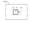
- FIG. 10 is a diagram illustrating a setting area. The outline of the image processing apparatus 100A will be described with reference to FIG.
- the area 536 set by the user is often set larger including the registration object 601.
- the template matching accuracy is lowered.
- the pixel change in the region sandwiched between the region 536 and the frame 1001 increases. In other words, the degree of variation of the pixels in the area increases.
- the image processing apparatus 100A can speed up the template matching process while maintaining the accuracy of template matching by generating the template image so that the variation degree of the region is small.
- FIG. 11 is a block diagram illustrating an example of a functional configuration of the image processing apparatus 100A.
- the functional configuration of the image processing apparatus 100A will be described with reference to FIG.
- Image processing apparatus 100A according to the present embodiment is different from image processing apparatus 100 according to the first embodiment in that template image generation unit 550 has alignment unit 551.
- the template image generation unit 550 includes an alignment unit 551.
- the alignment unit 551 scans the registered image and determines an area on the registered image (hereinafter also referred to as “determined area”) such that the degree of variation of the boundary area is relatively small.
- the template image generation unit 550 cuts out the template image at the position on the registered image determined by the alignment unit 551. Details of the template image cutout method of the template image generation unit 550 will be described later.
- FIG. 12 is a diagram illustrating a state in which the registered image is scanned in order to calculate the variation degree of the boundary region. Details of the operation of the alignment unit 551 will be described with reference to FIG.
- the image processing apparatus 100A scans the area 1200 in the registered image 413 enlarged by a predetermined width centering on the set area.
- the predetermined width is set at the time of design. Further, the predetermined width may be configured to be set by the user.
- the area 1200 may be an area 436 set by the user.
- the alignment unit 551 scans the area 1200 to calculate the degree of variation of the boundary area 1230 sandwiched between the outer frame 1210 that is the area of the same size as the determined size and the inner frame 1220 inside the area.
- the shape of the inner frame 1220 does not have to be a square, and may be any one of a circle, an ellipse, a polygon, and other shapes.
- Alignment unit 551 determines an area (determined area) where the calculated degree of variation is minimized.
- the template image generation unit 550 cuts out a determined area whose size matches the determined size as a template image.
- the template image generation unit 550 outputs the extracted template image to the position / orientation detection unit 560.
- the position / orientation detection unit 560 performs template matching using the template image.
- the image processing apparatus 100A generates a template image by extracting an area where the degree of variation of the boundary area is small, while maintaining the accuracy of template matching. It is possible to speed up the template matching process.
- Image processing apparatus 100B according to the present embodiment when the calculation amount associated with the image size does not exist in table 414, is known associated with each image size in a predetermined range based on the image size. This is different from the image processing apparatus 100 according to the first embodiment in that the estimation is based on the amount of calculation.
- FIG. 13 is a block diagram illustrating an example of a functional configuration of the image processing apparatus 100B.
- the functional configuration of the image processing apparatus 100B will be described with reference to FIG.
- Image processing apparatus 100B according to the present embodiment is different from image processing apparatus 100 according to the first embodiment in that determination unit 540 includes estimation unit 541.
- the determining unit 540 refers to a predetermined range of the table 414 on the basis of the size of the setting area, and determines an image size that relatively reduces the amount of calculation of the template matching process. At this time, when there is an image size for which the calculation amount is not defined in the table 414, the estimation unit 541 estimates an unknown calculation amount of template matching corresponding to the image size.
- the estimation unit 541 refers to a predetermined range of the table 414 based on the image size corresponding to the unknown calculation amount.
- the estimation unit 541 estimates an unknown calculation amount based on the known calculation amount in the referenced range. For example, the estimation unit 541 uses a calculation amount obtained by estimating an average of known calculation amounts.
- the estimation unit 541 calculates a weighted average by assigning a large weight to the calculation amount corresponding to the closer image size to the image size corresponding to the unknown calculation amount, and calculates the weighted average as the calculation amount. Also good.
- the image processing apparatus 100B according to the present embodiment can estimate from the known calculation amount when the calculation amount specified in the table is unknown, and can determine an appropriate image size. Further, the image processing apparatus 100B according to the present embodiment can reduce the capacity of the table.
- Image processing apparatus C according to the present embodiment is different from image processing apparatus 100 according to the first embodiment in that the template image is generated in the registration mode instead of the inspection mode. That is, the image processing apparatus C generates the template image offline instead of online.
- FIG. 14 is a flowchart showing a part of processing executed by image processing apparatus 100C.
- the processing in FIG. 14 is realized by the CPU 401 executing a program. In other aspects, some or all of the processing may be performed by circuit elements or other hardware. Only steps different from the flowchart of the process executed by image processing apparatus 100 according to the first embodiment will be described below. The description of other similar steps will not be repeated.
- steps S1410 and S1411 are executed.
- step S1410 the CPU 401 refers to a predetermined range of the table 414 based on the size of the setting area as the determination unit 540, and determines an image size (determined size) that relatively reduces the amount of calculation of the template matching process. decide.
- step S1410 the CPU 401 stores the template image in the auxiliary storage device 410.
- step S1411 the CPU 401 cuts out the template image from the registered image 413 with the determined size as the template image generation unit 550. At this time, the CPU 401 cuts out the center of the template image so as to coincide with the center of the setting area.
- step S1420 is executed.
- the CPU 401 obtains a template image stored in the auxiliary storage device 410.
- the image processing apparatus 100C speeds up template matching executed at the time of inspection (online) by generating the template image at the time of registration (offline) in advance. Can do.
- Image processing apparatus D according to the present embodiment is different from image processing apparatus 100 according to the first embodiment in that it further includes a function of updating a table.
- FIG. 15 is a block diagram illustrating an example of a functional configuration of the image processing apparatus 100D.
- a functional configuration of the image processing apparatus 100D will be described with reference to FIG.
- Image processing apparatus 100D according to the present embodiment is different from image processing apparatus 100 according to the first embodiment in that update unit 1510 is included.
- the other functions are the same. Therefore, description of the same function will not be repeated.
- the calculation time for template matching depends on the environment of the image processing device such as the MPU (Micro-Processing Unit), the structure of the memory, cache, etc., and the usage rate of the software memory that is driven during template matching. Difficult to predict theoretically. For this reason, the table 414 needs to be updated when any of the environments of the image processing apparatus changes.
- MPU Micro-Processing Unit
- the update unit 1510 updates the table 414. More specifically, the position / orientation detection unit 560 performs template matching processing using input images and template images of a plurality of sizes. The position / orientation detection unit 560 outputs the calculation time taken for the template matching process for each input image to the update unit 1510.
- the update unit 1510 updates the existing table 414 based on the calculation time corresponding to each image size output by the position / orientation detection unit 560.
- the image processing apparatus 100D updates the table according to the environment of the image processing apparatus when the environment of the image processing apparatus is changed. As a result, it is possible to calculate an exact template matching calculation time that matches the environment of the image processing apparatus, and to speed up the template matching process more reliably.
Abstract
Description
好ましくは、生成することは、決定された画像サイズ同様のサイズの外枠と、外枠の内側にある内枠とに挟まれる登録画像上の領域の変動度合いが相対的に小さくなるように、登録画像からテンプレートを生成することを含む。 Preferably, the center of the determined image size region coincides with the center of the received region.
Preferably, the generation is performed so that the degree of variation of the region on the registered image sandwiched between the outer frame having the same size as the determined image size and the inner frame inside the outer frame is relatively small. Generating a template from the registered image.
図1は、本実施の形態に従う画像処理装置100を含む画像処理システム1の全体構成を示す概略図である。図1を参照して、画像処理システム1は、たとえば、検査対象物(以下、「ワーク」ともいう。)の欠陥や汚れの有無を光学的に検査する。より具体的には、画像処理システム1は、生産ラインなどに組み込まれ、予め登録されたテンプレートを用いて、ワーク2を撮影して取得した画像とテンプレートマッチングを行う。 <Overall device configuration>
FIG. 1 is a schematic diagram showing an overall configuration of an
図2は、画像処理装置100の機能構成の一例を示すブロック図である。図2を参照して、画像処理装置100の機能構成の概要を説明する。 <Functional configuration>
FIG. 2 is a block diagram illustrating an example of a functional configuration of the
図4は、画像処理装置100のハードウェア構成の一例を示すブロック図である。図4を参照して、画像処理装置100のハードウェア構成について説明する。 <Hardware configuration>
FIG. 4 is a block diagram illustrating an example of a hardware configuration of the
以下、第1~第5の実施の形態について順に説明する。第1~第5の実施の形態に従う画像処理装置のハードウェア構成は、上述のハードウェア構成と同様である。したがって、ハードウェア構成の説明については繰り返さない。 <Overview>
Hereinafter, the first to fifth embodiments will be described in order. The hardware configuration of the image processing apparatus according to the first to fifth embodiments is the same as the hardware configuration described above. Therefore, the description of the hardware configuration will not be repeated.
<機能構成>
図5は、第1の実施の形態に従う画像処理装置100の機能構成の一例を示すブロック図である。図5を参照して、画像処理装置100の機能構成について説明する。 [First Embodiment]
<Functional configuration>
FIG. 5 is a block diagram showing an example of a functional configuration of the
画像処理装置100の動作モードが登録モードである場合、カメラ8は、ワークを撮影することで得られた登録画像を補助記憶装置410と、領域設定部520とに出力する。 (Registration mode)
When the operation mode of the
画像処理装置100は、動作モードが検査モードである場合に、テンプレートマッチングを実行する。 (Inspection mode)
The
図6は、登録画像上の設定領域を表す図である。図6を参照して、設定領域の詳細について説明する。 <Setting area>
FIG. 6 is a diagram illustrating a setting area on a registered image. Details of the setting area will be described with reference to FIG.
図7は、テーブル414のデータ構造を示す図である。図7を参照して、テーブル414のデータ構造について説明する。 <Table>
FIG. 7 is a diagram illustrating the data structure of the table 414. The data structure of the table 414 will be described with reference to FIG.
演算量は、テーブルではなく近似式で定義されてもよい。たとえば、演算量は、画像サイズと、計算量とから算出されてもよい。このとき、理論式が用いられる。サイズNの1次元のDFTはCooley-Turkyのアルゴリズムを使えば、O(NΣni)の計算量で計算できることが一般に知られている。このため、演算量は、O(NΣni)(niはNを素因数分解したときの各素数)を1次元のDFTの演算量として定義されてもよい。 <Approximation formula>
The amount of calculation may be defined by an approximate expression instead of a table. For example, the calculation amount may be calculated from the image size and the calculation amount. At this time, a theoretical formula is used. It is generally known that a one-dimensional DFT of size N can be calculated with a calculation amount of O (NΣni) by using a Cooley-Turky algorithm. For this reason, O (NΣni) (ni is each prime number when N is primed) may be defined as the calculation amount of the one-dimensional DFT.
図7を再び参照して、決定サイズについて説明する。決定部540は、設定領域のサイズを基準とするテーブル414内の予め定められた範囲の画像サイズの中からテンプレートマッチング処理の演算量が相対的に少なくなる画像サイズ(決定サイズ)を決定する。 <Determined size>
The determined size will be described with reference to FIG. 7 again. The
図8は、位置姿勢検出部560の機能構成の一例を示すブロック図である。図8を参照して、テンプレートマッチング処理の一例であるRIPOCについて説明する。 <Template matching process>
FIG. 8 is a block diagram illustrating an example of a functional configuration of the position /
図9は、画像処理装置100が実行する処理の一部を表わすフローチャートである。図9の処理は、CPU401がプログラムを実行することにより実現される。他の局面において、処理の一部又は全部が、回路素子その他のハードウェアによって実行されてもよい。 <Control flow>
FIG. 9 is a flowchart showing a part of processing executed by the
以上のようにして、本実施の形態の画像処理装置100は、テンプレートマッチングの演算量が少なくなる画像サイズのテンプレート画像を用いてテンプレートマッチングを行うことにより、テンプレートマッチング処理を高速化することができる。 <Advantages>
As described above, the
以下、第2の実施の形態に従う画像処理装置100Aについて説明する。本実施の形態に従う画像処理装置100Aは、決定サイズと同様のサイズの外枠と、外枠の内側にある内枠とに挟まれる登録画像上の領域(以下、「境界領域」ともいう。)の変動度合いが相対的に少なくなる領域をテンプレート画像として切り出す点が第1の実施の形態に従う画像処理装置100と異なる。したがって、設定領域とテンプレート画像との中心は必ずしも一致するわけではない。 [Second Embodiment]
Hereinafter,
図10は、設定領域を表す図である。図10を参照して、画像処理装置100Aの概要について説明する。 <Overview>
FIG. 10 is a diagram illustrating a setting area. The outline of the
図11は、画像処理装置100Aの機能構成の一例を示すブロック図である。図11を参照して、画像処理装置100Aの機能構成について説明する。本実施の形態に従う画像処理装置100Aは、テンプレート画像生成部550が位置合わせ部551を有する点が第1の実施の形態に従う画像処理装置100と異なる。 <Functional configuration>
FIG. 11 is a block diagram illustrating an example of a functional configuration of the
図12は、境界領域の変動度合いを算出するために登録画像内を走査している様子を表す図である。図12を参照して、位置合わせ部551の動作の詳細について説明する。 <Degree of fluctuation>
FIG. 12 is a diagram illustrating a state in which the registered image is scanned in order to calculate the variation degree of the boundary region. Details of the operation of the
以上のようにして、本実施の形態の画像処理装置100Aは、境界領域の変動度合いが小さくなるような領域を登録画像から切出してテンプレート画像として生成することで、テンプレートマッチングの精度を保ちつつ、テンプレートマッチング処理を高速化することが可能になる。 <Advantages>
As described above, the
以下、第3の実施の形態に従う画像処理装置100Bについて説明する。本実施の形態に従う画像処理装置100Bは、画像サイズに対応付けられる演算量がテーブル414に存在しない場合に、当該画像サイズを基準とする予め定められた範囲の画像サイズにそれぞれ対応付けられた既知の演算量に基づいて推定する点が、第1の実施の形態に従う画像処理装置100と異なる。 [Third Embodiment]
Hereinafter, an
図13は、画像処理装置100Bの機能構成の一例を示すブロック図である。図13を参照して、画像処理装置100Bの機能構成について説明する。本実施の形態に従う画像処理装置100Bは、決定部540が推定部541を有する点が第1の実施の形態に従う画像処理装置100と異なる。 <Overview>
FIG. 13 is a block diagram illustrating an example of a functional configuration of the
以上のようにして、本実施の形態の画像処理装置100Bは、テーブルに規定される演算量が未知である場合に既知の演算量から推定し、適切な画像サイズを決定することができる。また、本実施の形態の画像処理装置100Bは、テーブルの容量を削減することができる。 <Advantages>
As described above, the
以下、第4の実施の形態に従う画像処理装置Cについて説明する。本実施の形態に従う画像処理装置Cは、テンプレート画像が検査モードではなく登録モードで生成される点が、第1の実施の形態に従う画像処理装置100と異なる。つまり、画像処理装置Cは、テンプレート画像をオンラインではなくオフラインで生成する。 [Fourth Embodiment]
Hereinafter, an image processing apparatus C according to the fourth embodiment will be described. Image processing apparatus C according to the present embodiment is different from
図14は、画像処理装置100Cが実行する処理の一部を表わすフローチャートである。図14の処理は、CPU401がプログラムを実行することにより実現される。他の局面において、処理の一部又は全部が、回路素子その他のハードウェアによって実行されてもよい。以下では、第1の実施の形態に従う画像処理装置100が実行する処理のフローチャートと異なるステップについてのみ説明する。その他の同様のステップについては説明を繰り返さない。 <Overview>
FIG. 14 is a flowchart showing a part of processing executed by image processing apparatus 100C. The processing in FIG. 14 is realized by the
以上のようにして、本実施の形態の画像処理装置100Cは、テンプレート画像が登録時(オフライン)で予め生成しておくことにより、検査時(オンライン)に実行されるテンプレートマッチングを高速化することができる。 <Advantages>
As described above, the image processing apparatus 100C according to the present embodiment speeds up template matching executed at the time of inspection (online) by generating the template image at the time of registration (offline) in advance. Can do.
以下、第5の実施の形態に従う画像処理装置Dについて説明する。本実施の形態に従う画像処理装置Dは、テーブルを更新する機能をさらに含む点が第1の実施の形態に従う画像処理装置100と異なる。 [Fifth Embodiment]
Hereinafter, an image processing apparatus D according to the fifth embodiment will be described. Image processing apparatus D according to the present embodiment is different from
図15は、画像処理装置100Dの機能構成の一例を示すブロック図である。図15を参照して、画像処理装置100Dの機能構成について説明する。本実施の形態に従う画像処理装置100Dは、更新部1510を含む点が第1の実施の形態に従う画像処理装置100と異なる。その他の機能については同様である。そのため、同様の機能については説明を繰り返さない。 <Functional configuration>
FIG. 15 is a block diagram illustrating an example of a functional configuration of the
以上のようにして、本実施の形態の画像処理装置100Dは、画像処理装置の環境が代わった場合などに、画像処理装置の環境に合わせてテーブルを更新する。これにより、画像処理装置の環境に合わせた正確なテンプレートマッチングの演算時間を算出することができ、テンプレートマッチング処理をより確実に高速化することができる。 <Advantages>
As described above, the
Claims (15)
- テンプレートを用いてマッチング処理を行う画像処理方法であって、
基準となる目的の対象物を撮像することで得られた登録画像に対する領域の設定を受付けることと、
前記受付けた領域のサイズを基準とする予め定められた範囲の画像サイズの中から、画像サイズに予め対応付けられた前記マッチング処理の演算量が相対的に少なくなる画像サイズを決定することと、
前記決定された画像サイズの領域の情報に基づいて前記テンプレートを前記登録画像から生成することとを備える、画像処理方法。 An image processing method for performing a matching process using a template,
Receiving an area setting for a registered image obtained by imaging a target object as a reference;
Determining an image size in which the amount of calculation of the matching process associated in advance with an image size is relatively small, from among image sizes in a predetermined range based on the size of the received region;
An image processing method comprising: generating the template from the registered image based on information on a region of the determined image size. - 前記決定することは、前記受付けた前記領域のサイズを基準とする予め定められた範囲の画像サイズの中から、前記マッチング処理の演算量が最小となる画像サイズを決定することを含む、請求項1に記載の画像処理方法。 The determining includes determining an image size that minimizes an amount of calculation of the matching process from image sizes in a predetermined range based on the size of the received region. 2. The image processing method according to 1.
- 前記決定することは、前記受付けた前記領域のサイズの縦幅よりも小さい縦幅の画像サイズを決定することを含む、請求項1または2に記載の画像処理方法。 3. The image processing method according to claim 1, wherein the determining includes determining an image size having a vertical width smaller than a vertical width of the received area.
- 前記決定することは、前記受付けた前記領域のサイズの横幅よりも小さい横幅の画像サイズを決定することを含む、請求項1~3のいずれか1項に記載の画像処理方法。 4. The image processing method according to claim 1, wherein the determining includes determining an image size having a width smaller than a width of the received area.
- 前記決定された画像サイズの前記領域の中心は、前記受付けた前記領域の中心に一致する、前記請求項1~4のいずれか1項に記載の画像処理方法。 5. The image processing method according to claim 1, wherein a center of the area having the determined image size coincides with a center of the received area.
- 前記生成することは、前記決定された画像サイズ同様のサイズの外枠と、前記外枠の内側にある内枠とに挟まれる前記登録画像上の領域の変動度合いが相対的に小さくなるように、前記登録画像から前記テンプレートを生成することを含む、請求項1~4のいずれか1項に記載の画像処理方法。 The generation is performed so that the degree of fluctuation of the region on the registered image sandwiched between the outer frame having the same size as the determined image size and the inner frame inside the outer frame is relatively small. The image processing method according to claim 1, further comprising: generating the template from the registered image.
- 前記決定することは、画像サイズに対応する前記演算量が未知の場合に、当該画像サイズを基準とする予め定められた範囲の画像サイズにそれぞれ対応付けられた既知の演算量に基づいて当該画像サイズに対応する演算量を推定することを含む、請求項1~6のいずれか1項に記載の画像処理方法。 In the case where the calculation amount corresponding to the image size is unknown, the determination is based on the known calculation amount respectively associated with the image size in a predetermined range based on the image size. The image processing method according to any one of claims 1 to 6, further comprising estimating a calculation amount corresponding to the size.
- 前記演算量は、前記マッチング処理の全部または一部の実測された演算時間である、請求項1~7のいずれか1項に記載の画像処理方法。 The image processing method according to any one of claims 1 to 7, wherein the calculation amount is an actually calculated calculation time of all or part of the matching process.
- 前記演算量は、画像サイズと、前記マッチング処理の計算量とに基づいて定められる、請求項1~7のいずれか1項に記載の画像処理方法。 The image processing method according to any one of claims 1 to 7, wherein the calculation amount is determined based on an image size and a calculation amount of the matching process.
- 前記マッチング処理は、検査対象物を撮像することで得られた入力画像から前記検査対象物の位置を検出する処理を含み、
前記演算量は、前記位置を検出するのにかかる時間に基づいて定められる、請求項1~7のいずれか1項に記載の画像処理方法。 The matching process includes a process of detecting the position of the inspection object from an input image obtained by imaging the inspection object;
The image processing method according to any one of claims 1 to 7, wherein the calculation amount is determined based on a time taken to detect the position. - 前記演算量は、前記マッチング処理におけるフーリエ変換にかかる時間に基づいて定められる、請求項1~7のいずれか1項に記載の画像処理方法。 The image processing method according to any one of claims 1 to 7, wherein the calculation amount is determined based on a time required for Fourier transform in the matching processing.
- 画像サイズに予め対応付けられた前記演算量を更新することをさらに備える、請求項1~11のいずれか1項に記載の画像処理方法。 The image processing method according to any one of claims 1 to 11, further comprising updating the calculation amount associated in advance with an image size.
- テンプレートを用いてマッチング処理を行う画像処理装置であって、
基準となる目的の対象物を撮像することで得られた登録画像に対する領域の設定を受付けるための受付部と、
前記受付けた領域のサイズを基準とする予め定められた範囲の画像サイズの中から、画像サイズに予め対応付けられた前記マッチング処理の演算量が相対的に少なくなる画像サイズを決定するための決定部と、
前記決定された画像サイズの領域の情報に基づいて前記テンプレートを前記登録画像から生成するための生成部とを備える、画像処理装置。 An image processing apparatus that performs a matching process using a template,
An accepting unit for accepting an area setting for a registered image obtained by imaging a target object as a reference;
Determination for determining an image size in which the amount of calculation of the matching process associated in advance with an image size is relatively small from among image sizes in a predetermined range based on the size of the received region And
An image processing apparatus comprising: a generation unit configured to generate the template from the registered image based on information on the determined image size area. - 前記画像処理装置は、前記画像サイズと、前記マッチング処理の演算量との関係を規定するテーブルを格納するための記憶部をさらに備え、
前記決定部は、前記テーブルを参照して、前記マッチング処理の演算量が相対的に少なくなる画像サイズを決定するように構成されている、請求項13に記載の画像処理装置。 The image processing apparatus further includes a storage unit for storing a table that defines a relationship between the image size and the amount of calculation of the matching process,
The image processing apparatus according to claim 13, wherein the determination unit is configured to determine an image size with which a calculation amount of the matching process is relatively reduced with reference to the table. - テンプレートを用いてマッチング処理をコンピュータに実行させるためのプログラムであって、
前記プログラムは、前記コンピュータに、基準となる目的の対象物を撮像することで得られた登録画像に対する領域の設定を受付けることと、
前記受付けた領域のサイズを基準とする予め定められた範囲の画像サイズの中から、画像サイズに予め対応付けられた前記マッチング処理の演算量が相対的に少なくなる画像サイズを決定することと、
前記決定された画像サイズの領域の情報に基づいて前記テンプレートを前記登録画像から生成することとを実行させる、画像処理プログラム。 A program for causing a computer to execute matching processing using a template,
The program accepts a setting of a region for a registered image obtained by imaging a target object serving as a reference to the computer;
Determining an image size in which the amount of calculation of the matching process associated in advance with an image size is relatively small, from among image sizes in a predetermined range based on the size of the received region;
An image processing program causing the template to be generated from the registered image based on information on the determined image size area.
Priority Applications (3)
| Application Number | Priority Date | Filing Date | Title |
|---|---|---|---|
| JP2015522696A JPWO2014203687A1 (en) | 2013-06-17 | 2014-05-26 | Image processing method, image processing apparatus, and image processing program |
| EP14814421.5A EP3012803A4 (en) | 2013-06-17 | 2014-05-26 | Image processing method, image processing device, and image processing program |
| US14/899,077 US20160125266A1 (en) | 2013-06-17 | 2014-05-26 | Image Processing Method, Image Processing Device, And Image Processing Program |
Applications Claiming Priority (2)
| Application Number | Priority Date | Filing Date | Title |
|---|---|---|---|
| JP2013126382 | 2013-06-17 | ||
| JP2013-126382 | 2013-06-17 |
Publications (1)
| Publication Number | Publication Date |
|---|---|
| WO2014203687A1 true WO2014203687A1 (en) | 2014-12-24 |
Family
ID=52104429
Family Applications (1)
| Application Number | Title | Priority Date | Filing Date |
|---|---|---|---|
| PCT/JP2014/063826 WO2014203687A1 (en) | 2013-06-17 | 2014-05-26 | Image processing method, image processing device, and image processing program |
Country Status (4)
| Country | Link |
|---|---|
| US (1) | US20160125266A1 (en) |
| EP (1) | EP3012803A4 (en) |
| JP (1) | JPWO2014203687A1 (en) |
| WO (1) | WO2014203687A1 (en) |
Families Citing this family (8)
| Publication number | Priority date | Publication date | Assignee | Title |
|---|---|---|---|---|
| JP6158950B2 (en) * | 2013-12-27 | 2017-07-05 | シャープ株式会社 | Resolution estimation device |
| TWI606870B (en) * | 2015-11-04 | 2017-12-01 | 澧達科技股份有限公司 | Electronic product sorting system and sorting method |
| JP7080771B2 (en) * | 2018-08-29 | 2022-06-06 | 株式会社ミマキエンジニアリング | Processing data generation program, processing data generation system and processing data generation method |
| US10574848B1 (en) * | 2018-10-26 | 2020-02-25 | Toshiba Tec Kabushiki Kaisha | Information processing apparatus with registered image detection |
| CN109584149B (en) * | 2018-11-28 | 2023-03-07 | 东软集团股份有限公司 | Image processing method, device, equipment and computer readable storage medium |
| CN110930362B (en) * | 2019-10-23 | 2023-10-27 | 北京图知天下科技有限责任公司 | Screw safety detection method, device and system |
| CN111626984B (en) * | 2020-04-17 | 2022-04-08 | 广州冠粤路桥检测有限公司 | Material geometric dimension detection method based on image comparison |
| CN111612760B (en) * | 2020-05-20 | 2023-11-17 | 阿波罗智联(北京)科技有限公司 | Method and device for detecting obstacles |
Citations (4)
| Publication number | Priority date | Publication date | Assignee | Title |
|---|---|---|---|---|
| JP2000003444A (en) | 1998-06-15 | 2000-01-07 | Hitachi Ltd | Pattern matching method |
| JP2006091790A (en) * | 2004-09-27 | 2006-04-06 | Toshiba Corp | Pattern inspecting method |
| JP2008232933A (en) * | 2007-03-22 | 2008-10-02 | Hitachi High-Technologies Corp | Image processing system and scanning electron microscope system |
| JP2010002425A (en) * | 2009-09-16 | 2010-01-07 | Hitachi High-Technologies Corp | Foreign matter inspection apparatus |
Family Cites Families (8)
| Publication number | Priority date | Publication date | Assignee | Title |
|---|---|---|---|---|
| US6636635B2 (en) * | 1995-11-01 | 2003-10-21 | Canon Kabushiki Kaisha | Object extraction method, and image sensing apparatus using the method |
| EP1693783B1 (en) * | 2005-02-21 | 2009-02-11 | Mitsubishi Electric Information Technology Centre Europe B.V. | Fast method of object detection by statistical template matching |
| JP2007102634A (en) * | 2005-10-06 | 2007-04-19 | Sony Corp | Image processor |
| JP2008158626A (en) * | 2006-12-21 | 2008-07-10 | Nippon Telegr & Teleph Corp <Ntt> | Template creation device, template creation method, template creation program implementing the method, storage medium with the program stored therein, template matching device, template matching method, template matching program implementing the method, and storage medium with the program stored therein |
| WO2008129875A1 (en) * | 2007-04-13 | 2008-10-30 | Panasonic Corporation | Detector, detection method, and integrated circuit for detection |
| US7974475B1 (en) * | 2009-08-20 | 2011-07-05 | Thomas Cecil Minter | Adaptive bayes image correlation |
| WO2014024854A1 (en) * | 2012-08-10 | 2014-02-13 | コニカミノルタ株式会社 | Image processing device, image processing method, and image processing program |
| US20160070985A1 (en) * | 2013-05-02 | 2016-03-10 | Konica Minolta Inc. | Image processing apparatus, image processing method, and storage medium storing image processing program thereon |
-
2014
- 2014-05-26 US US14/899,077 patent/US20160125266A1/en not_active Abandoned
- 2014-05-26 EP EP14814421.5A patent/EP3012803A4/en not_active Withdrawn
- 2014-05-26 JP JP2015522696A patent/JPWO2014203687A1/en active Pending
- 2014-05-26 WO PCT/JP2014/063826 patent/WO2014203687A1/en active Application Filing
Patent Citations (4)
| Publication number | Priority date | Publication date | Assignee | Title |
|---|---|---|---|---|
| JP2000003444A (en) | 1998-06-15 | 2000-01-07 | Hitachi Ltd | Pattern matching method |
| JP2006091790A (en) * | 2004-09-27 | 2006-04-06 | Toshiba Corp | Pattern inspecting method |
| JP2008232933A (en) * | 2007-03-22 | 2008-10-02 | Hitachi High-Technologies Corp | Image processing system and scanning electron microscope system |
| JP2010002425A (en) * | 2009-09-16 | 2010-01-07 | Hitachi High-Technologies Corp | Foreign matter inspection apparatus |
Non-Patent Citations (3)
| Title |
|---|
| "Symmetric Phase-Only Matched Filtering of Fourier-Mellin Transforms for Image Registration and Recognition", IEEE TRANSACTIONS ON PATTERN ANALYSIS AND MACHINE INTELLIGENCE, vol. I6, no. 12, December 1994 (1994-12-01) |
| HITOSHI KIYA: "Merging of Image Signal Processing and Image Pattern Recognition - DCT Code Only Correlation and Its Applications", TOKYO METROPOLITAN UNIVERSITY, THE FACULTY OF SYSTEM DESIGN, WORKSHOP FOR PRACTICAL UTILIZATION OF DYNAMIC IMAGE PROCESSING 2007, 8 March 2007 (2007-03-08) |
| See also references of EP3012803A4 |
Also Published As
| Publication number | Publication date |
|---|---|
| EP3012803A1 (en) | 2016-04-27 |
| US20160125266A1 (en) | 2016-05-05 |
| JPWO2014203687A1 (en) | 2017-02-23 |
| EP3012803A4 (en) | 2017-01-25 |
Similar Documents
| Publication | Publication Date | Title |
|---|---|---|
| WO2014203687A1 (en) | Image processing method, image processing device, and image processing program | |
| JP5297403B2 (en) | Position / orientation measuring apparatus, position / orientation measuring method, program, and storage medium | |
| US10586331B2 (en) | Diagnosis assisting device, image processing method in diagnosis assisting device, and non-transitory storage medium having stored therein program | |
| WO2019042426A1 (en) | Augmented reality scene processing method and apparatus, and computer storage medium | |
| CN111222395A (en) | Target detection method and device and electronic equipment | |
| CN114556268B (en) | Gesture recognition method and device and storage medium | |
| JP6483168B2 (en) | System and method for efficiently scoring a probe in an image with a vision system | |
| US8582810B2 (en) | Detecting potential changed objects in images | |
| WO2015035462A1 (en) | Point feature based 2d-3d registration | |
| JP5541426B1 (en) | Image processing apparatus, image processing method, and image processing program | |
| KR20150114950A (en) | Increasing frame rate of an image stream | |
| KR20220093492A (en) | System and method for establishing structural exterior map using image stitching | |
| CN111583417A (en) | Method and device for constructing indoor VR scene with combined constraint of image semantics and scene geometry, electronic equipment and medium | |
| CN109859313B (en) | 3D point cloud data acquisition method and device, and 3D data generation method and system | |
| JP5310402B2 (en) | Image conversion parameter calculation apparatus, image conversion parameter calculation method, and program | |
| RU2737193C1 (en) | Method of monitoring moving body | |
| JP2020204880A (en) | Learning method, program, and image processing device | |
| JP2016206909A (en) | Information processor, and information processing method | |
| CN115205224A (en) | Adaptive feature-enhanced multi-source fusion visual detection method, device and medium | |
| JP6056354B2 (en) | Image processing apparatus, image processing method, and image processing program | |
| JP6431495B2 (en) | Teacher data generation method | |
| CN112991179B (en) | Method, apparatus, device and storage medium for outputting information | |
| JP2018156442A (en) | Estimator learning device, normal line direction estimation device, method and program | |
| JP2006003276A (en) | Three dimensional geometry measurement system | |
| Safrudin et al. | Object detection Cascaded canny edge with SURF method in quadcopter drone simulation |
Legal Events
| Date | Code | Title | Description |
|---|---|---|---|
| 121 | Ep: the epo has been informed by wipo that ep was designated in this application |
Ref document number: 14814421 Country of ref document: EP Kind code of ref document: A1 |
|
| ENP | Entry into the national phase |
Ref document number: 2015522696 Country of ref document: JP Kind code of ref document: A |
|
| WWE | Wipo information: entry into national phase |
Ref document number: 2014814421 Country of ref document: EP |
|
| WWE | Wipo information: entry into national phase |
Ref document number: 14899077 Country of ref document: US |
|
| NENP | Non-entry into the national phase |
Ref country code: DE |