WO2014203546A1 - Frequency resource allocation method and base station device - Google Patents
Frequency resource allocation method and base station device Download PDFInfo
- Publication number
- WO2014203546A1 WO2014203546A1 PCT/JP2014/050700 JP2014050700W WO2014203546A1 WO 2014203546 A1 WO2014203546 A1 WO 2014203546A1 JP 2014050700 W JP2014050700 W JP 2014050700W WO 2014203546 A1 WO2014203546 A1 WO 2014203546A1
- Authority
- WO
- WIPO (PCT)
- Prior art keywords
- mobile station
- frequency
- frequency resource
- allocation
- correction value
- Prior art date
Links
Images


Classifications
-
- H—ELECTRICITY
- H04—ELECTRIC COMMUNICATION TECHNIQUE
- H04W—WIRELESS COMMUNICATION NETWORKS
- H04W72/00—Local resource management
- H04W72/04—Wireless resource allocation
- H04W72/044—Wireless resource allocation based on the type of the allocated resource
- H04W72/0453—Resources in frequency domain, e.g. a carrier in FDMA
-
- H—ELECTRICITY
- H04—ELECTRIC COMMUNICATION TECHNIQUE
- H04L—TRANSMISSION OF DIGITAL INFORMATION, e.g. TELEGRAPHIC COMMUNICATION
- H04L5/00—Arrangements affording multiple use of the transmission path
- H04L5/0001—Arrangements for dividing the transmission path
- H04L5/0003—Two-dimensional division
- H04L5/0005—Time-frequency
- H04L5/0007—Time-frequency the frequencies being orthogonal, e.g. OFDM(A), DMT
-
- H—ELECTRICITY
- H04—ELECTRIC COMMUNICATION TECHNIQUE
- H04L—TRANSMISSION OF DIGITAL INFORMATION, e.g. TELEGRAPHIC COMMUNICATION
- H04L5/00—Arrangements affording multiple use of the transmission path
- H04L5/003—Arrangements for allocating sub-channels of the transmission path
- H04L5/0037—Inter-user or inter-terminal allocation
- H04L5/0039—Frequency-contiguous, i.e. with no allocation of frequencies for one user or terminal between the frequencies allocated to another
-
- H—ELECTRICITY
- H04—ELECTRIC COMMUNICATION TECHNIQUE
- H04L—TRANSMISSION OF DIGITAL INFORMATION, e.g. TELEGRAPHIC COMMUNICATION
- H04L5/00—Arrangements affording multiple use of the transmission path
- H04L5/003—Arrangements for allocating sub-channels of the transmission path
- H04L5/0044—Arrangements for allocating sub-channels of the transmission path allocation of payload
-
- H—ELECTRICITY
- H04—ELECTRIC COMMUNICATION TECHNIQUE
- H04L—TRANSMISSION OF DIGITAL INFORMATION, e.g. TELEGRAPHIC COMMUNICATION
- H04L5/00—Arrangements affording multiple use of the transmission path
- H04L5/003—Arrangements for allocating sub-channels of the transmission path
- H04L5/0058—Allocation criteria
- H04L5/006—Quality of the received signal, e.g. BER, SNR, water filling
-
- H—ELECTRICITY
- H04—ELECTRIC COMMUNICATION TECHNIQUE
- H04W—WIRELESS COMMUNICATION NETWORKS
- H04W72/00—Local resource management
- H04W72/50—Allocation or scheduling criteria for wireless resources
- H04W72/54—Allocation or scheduling criteria for wireless resources based on quality criteria
-
- H—ELECTRICITY
- H04—ELECTRIC COMMUNICATION TECHNIQUE
- H04L—TRANSMISSION OF DIGITAL INFORMATION, e.g. TELEGRAPHIC COMMUNICATION
- H04L5/00—Arrangements affording multiple use of the transmission path
- H04L5/0001—Arrangements for dividing the transmission path
- H04L5/0014—Three-dimensional division
- H04L5/0023—Time-frequency-space
-
- H—ELECTRICITY
- H04—ELECTRIC COMMUNICATION TECHNIQUE
- H04L—TRANSMISSION OF DIGITAL INFORMATION, e.g. TELEGRAPHIC COMMUNICATION
- H04L5/00—Arrangements affording multiple use of the transmission path
- H04L5/003—Arrangements for allocating sub-channels of the transmission path
- H04L5/0048—Allocation of pilot signals, i.e. of signals known to the receiver
-
- H—ELECTRICITY
- H04—ELECTRIC COMMUNICATION TECHNIQUE
- H04L—TRANSMISSION OF DIGITAL INFORMATION, e.g. TELEGRAPHIC COMMUNICATION
- H04L5/00—Arrangements affording multiple use of the transmission path
- H04L5/003—Arrangements for allocating sub-channels of the transmission path
- H04L5/0053—Allocation of signaling, i.e. of overhead other than pilot signals
Definitions
- the present invention relates to a frequency resource allocation method and a frequency base station apparatus that performs frequency resource allocation in a frequency division multiple access (OFDMA: Orthogonal Frequency-Division Multiple Access) scheme.
- OFDMA Orthogonal Frequency-Division Multiple Access
- frequency resources are allocated as follows when performing multi-user communication.
- each mobile station measures the power of the reference signal transmitted from the base station for each frequency resource, and connects the propagation quality (Channel Quality Information: CQI) such as the signal-to-interference power ratio for each frequency resource.
- CQI Channel Quality Information
- the base station allocates frequency resources according to the propagation quality information transmitted from the subordinate mobile stations.
- inter-cell interference is affected by the allocation status of frequency resources in each cell, the direction of the transmission beam of the base station, the direction of the reception beam of the mobile station, and the like. For this reason, simply allocating frequency resources using the reference signal transmitted from the base station reflects the frequency resource allocation status and the influence of the transmission beam on the inter-cell interference of the data signal transmitted on the shared channel. Can not do it. Therefore, as a method of performing frequency resource allocation in consideration of interference between cells, it is known to notify the frequency resource allocation status in each cell between cells and correct the propagation quality measured by the reference signal. ing.
- n is a mobile station number
- CQI_offset is an offset value of propagation quality expressed in decibel values
- ⁇ adj is an update value of an offset value expressed in decibel values
- BLERtarget is a target value of block error rate.
- the offset value is increased by ⁇ adj ⁇ BLERtarget when the communication is successful, and the offset value by ⁇ adj ⁇ (1 ⁇ BLERtarget) when the communication is unsuccessful. Make it smaller. If communication is not performed, the offset value remains unchanged.
- Patent Document 1 dynamically allocates radio resources at regular intervals when the data size to be transmitted is greater than or equal to the threshold, and allocates radio resources at regular intervals when the data size to be transmitted is less than the threshold. Assigned radio resources are described.
- the base station creates an interference information table based on the quality information of the uplink channel and notifies the mobile station, and the mobile station determines the frequency band of the pilot signal (the above reference signal), Requesting transmission resources from the base station is described.
- Patent Document 3 describes that a terminal apparatus generates channel state information for each of a plurality of resource regions or for each channel state information transmission cycle using an offset value received from a base station.
- ACK / NACK information used for outer loop processing is transmitted for each communication channel, not for each frequency channel. That is, when a plurality of frequency resources constitute one communication channel, the ACK / NACK information is transmitted as an overall communication result of the plurality of frequency resources. For this reason, even if only some of the frequency resources are interfering, it is determined that the quality of other frequency resources is low due to the influence.
- the present invention provides a frequency resource allocation method and a base station apparatus that can solve such problems and at least reduce the influence on the allocation of other frequency resources due to the degradation of the quality of some frequency resources. With the goal.
- a base station performing frequency division multiple access communication to allocate frequency resources for downlink to each mobile station, from each mobile station, propagation quality information for each frequency resource, A step of receiving whether or not data is correctly received in the entire frequency resource assigned to the mobile station, and for each mobile station, based on the propagation quality information received from the mobile station and the determination result
- a step of calculating an allocation index for allocating frequency resources, and a step of allocating frequency resources to each mobile station based on the allocation index, and the step of calculating the allocation index is assigned to the mobile station
- a correction value based on the determination result is obtained for each group in which the frequency resources are divided into a plurality of groups. From the correction value for each-loop and propagation quality information, the frequency resource allocation method and calculates the allocation indicator is provided.
- the propagation quality information for each frequency resource from each mobile station and the frequency assigned to the mobile station A means for receiving whether or not data has been correctly received for the entire resource, and for each mobile station, based on the propagation quality information received from the mobile station and the result of availability determination, a frequency resource is assigned to the mobile station. Means for calculating an allocation index for allocation, and means for allocating a frequency resource to each mobile station based on the allocation index. The means for calculating the allocation index includes a plurality of frequency resources allocated to the mobile station. From the means for obtaining a correction value based on the determination result for each group divided into, and the correction value and propagation quality information for each group
- the base station apparatus is provided, characterized in that it comprises means for abutting calculating an index Ri, a.
- the present invention it is possible to at least reduce the influence on the allocation of other frequency resources due to the deterioration of the quality of some frequency resources.
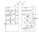
- FIG. 1 is a block diagram illustrating a wireless communication system that implements the present invention. Here, in order to simplify the description, only the configuration related to the downlink is shown.
- This wireless communication system includes a base station 10 and a mobile station 20.
- the base station 10 includes a reference signal transmitter 11, a propagation quality / ACK / NACK receiver 12, an allocation index calculator 13, a scheduler 14, a data transmitter 15, and a transmission / reception antenna 16 as a configuration related to the downlink.
- the mobile station 20 includes a propagation quality measuring device 21, a propagation quality / ACK / NACK transmitter 22, a data receiver 23, an ACK / NACK determiner 24, and a transmission / reception antenna 25 as a configuration related to the downlink.
- the reference signal transmitter 11 of the base station 10 generates a reference signal and transmits it from the transmission / reception antenna 16.
- the scheduler 14 determines the assignment of each mobile station to frequency resources.
- the data transmitter 15 assigns the data of each mobile station to the frequency resource according to the assignment of the scheduler 14 and transmits it from the transmission / reception antenna 16.
- the propagation quality measuring device 21 extracts the reference signal from the signal received by the transmission / reception antenna 25 and measures the propagation quality.
- the propagation quality / ACK / NACK transmitter 22 transmits the propagation quality measured by the propagation quality measuring unit 21 from the transmission / reception antenna 25.
- the data receiver 23 receives a data signal from the signal received by the transmission / reception antenna 25.
- the ACK / NACK determiner 24 determines ACK / NACK depending on whether the data is correctly received by the data receiver 23. This determination result is transmitted from the transmission / reception antenna 25 by the propagation quality / ACK / NACK transmitter 22 as ACK / NACK information.
- Propagation quality / ACK / NACK receiver 12 of base station 10 determines whether or not data has been correctly received from each mobile station for the propagation quality information for each frequency resource and the entire frequency resource assigned to the mobile station. The resulting ACK / NACK information is detected from the signal received by the transmission / reception antenna 16.
- the allocation index calculator 13 calculates, for each mobile station, an allocation index for allocating frequency resources to the mobile station based on the propagation quality information and ACK / NACK information received from the mobile station. In this calculation, the allocation index calculator 13 obtains a correction value based on the determination result for each group in which the frequency resource allocated to the mobile station is divided into a plurality, and the correction value and propagation quality information for each group From this, the allocation index is obtained.
- the scheduler 14 determines allocation of transmission data of each mobile station to frequency resources based on the allocation index obtained by the calculation of the allocation index calculator 13.
- FIG. 2 is a diagram illustrating interference between cells.
- base stations 31 and 32 base stations 31 and 32
- mobile stations 41, 42, and 43 mobile stations 41, 42, and 43
- the mobile stations 41 and 42 are connected to the base station 31 and the mobile station 43 is connected to the base station 32.
- transmission from the base station 32 to the mobile station 43 may cause interference in the mobile station 41.
- FIG. 3 shows an example of frequency resource allocation index in the example of FIG.
- the frequency resource is expressed as nine frequency channels.
- the right-down hatching indicates an allocation index for the mobile station 41, and the right-up hatching indicates an allocation index for the mobile station 42.
- the frequency channel is allocated to a mobile station having a high allocation index in each frequency channel.
- FIG. 4 shows an example of frequency resource allocation in the example of FIG.
- the base station 31 assigns frequency channels # 3 and # 4 to the mobile station 41 and frequency channels # 6 to # 8 to the mobile station.
- the unassigned frequency channel may be assigned to the mobile stations 41 and 42, or may be assigned to another mobile station under the base station 31.
- the base station 32 assigns frequency channels # 1 to # 3 to the mobile station 43.
- the frequency channel # 3 is assigned to the mobile station 41 in the base station 31 and to the mobile station 43 in the base station 32.
- the transmission of the frequency channel # 3 from the base station 32 to the mobile station 43 may be This may cause interference in transmission of the frequency channel # 3 from the mobile station 31 to the mobile station 41.
- the reception quality of the frequency channel # 3 is deteriorated from the quality corresponding to the allocation index of FIG.
- the ACK / NACK information is transmitted not for each frequency channel but for each communication channel in a system such as LTE (Long Term Evolution) of 3GPP (Third Generation Partnership Project). Therefore, if the frequency channels # 3 and # 4 constitute one communication channel, ACK / NACK information is transmitted as a total communication result of the frequency channels # 3 and # 4. Therefore, even if only the frequency channel # 3 is interfering, both the frequency channels # 3 and # 4 are of low quality for the mobile station 41 due to the influence.
- LTE Long Term Evolution
- 3GPP Third Generation Partnership Project
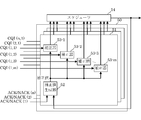
- FIG. 5 is a block diagram showing a circuit configuration for calculating the allocation index.
- An allocation index calculator 50 shown in FIG. 5 obtains a correction value of an allocation index by the outer loop processing shown in Equation 1, and is a background art for the allocation index calculator 13 in FIG.
- the allocation index calculator 50 includes a correction processor 51 for each mobile station.
- Each correction processor 51 includes one correction value generator 52 and correctors 53-1 to 53-m for each frequency channel assigned to the mobile station.
- the correction value generator 52 generates a correction value according to Equation 1 according to the ACK / NACK information and the presence / absence of frequency channel assignment notified from the scheduler 14.
- the correctors 53-1 to 53-m calculate the allocation index of each frequency channel from the propagation quality information report CQI (n, m), and correct the allocation index using the correction value calculated by the correction value generator 52. .
- the scheduler 14 determines the assignment of each frequency channel to each mobile station according to the assignment index of each frequency channel of each mobile station.
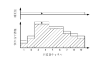
- FIG. 6 and FIG. 7 show examples of correcting the assignment index according to the background art shown in FIG.
- the offset value of the outer loop process is one for each mobile station so that there is one correction value generator 52.
- the allocation index is uniformly corrected in all frequency channels, and is corrected small in the example of FIG. 6 and largely corrected in the example of FIG. That is, in the correction by the outer loop process, the frequency characteristic does not change in the allocation index for each mobile station.
- the correction of the frequency channel assignment index cannot reflect interference between cells unless the frequency characteristics are changed.
- the correction value should not be applied uniformly to all frequency channels, but only to the frequency channel represented by the ACK / NACK information. Should be reflected.
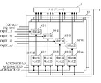
- FIG. 8 is a block diagram showing a configuration example of the allocation index calculator 13 shown in FIG. Here, it is assumed that frequency resources are assigned to each frequency channel, and a case where a correction value is obtained for each frequency channel will be described as an example.
- the allocation index calculator 13 includes a correction processor 61 for each mobile station, and each correction processor 61 corrects a correction value based on ACK / NACK information for each of m frequency channels allocated to the corresponding mobile station.
- the correction value generators 62-1 to 62-m according to the frequency channel assignment result notified from the scheduler 14, for the assigned frequency channel, according to the ACK / NACK information, the outer loop correction value. (Offset value) is updated.
- the correctors 63-1 to 63-m calculate the allocation index of each frequency channel from the propagation quality information report CQI (n, m), and use the correction values calculated by the correction value generators 62-1 to 62-m. , Correct the allocation index.
- the update of the correction value in the correction value generators 62-1 to 62-m is represented by the following equation.
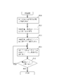
- FIG. 9 shows a processing flow of the frequency resource allocation method in the embodiment of the present invention shown in FIG. 1 and FIG.
- each frequency resource is shown.
- the frequency resource may be the same size as the frequency channel or a group of several frequency channels.
- the correction value CQI_offset (n, m) is updated for each mobile station and for each frequency channel (step S12). This update is performed according to Equation 2 depending on whether the frequency channel m has been assigned to the mobile station n and the ACK / NACK information ACK / NACK (n).
- the correctors 63-1 to 63-m in the allocation index calculator 13 calculate the allocation index for each mobile station and each frequency channel from the propagation quality information CQI (n, m), and the correction calculated in step S12. Correction is performed with the value CQI_offset (n, m) (step S13).
- the scheduler 14 allocates the frequency channel to the mobile station according to the allocation index calculated in Step S13 (Step S14).
- the scheduler 14 also checks whether there is an unassigned frequency channel (step S15). If there is an unassigned frequency channel, the scheduler 14 returns to step S14, and if there is no unassigned frequency channel, the assignment ends.
- FIG. 10 is a diagram showing the process of step S12 in FIG. 9 in more detail.
- the allocation index calculator 13 shown in FIG. 8 is provided with correction value generators 62-1 to 62-m for each mobile station and each frequency channel.
- the operations of these correction value generators 62-1 to 62-m can also be realized by sequential processing as shown in FIG.
- step S21 the number n of the mobile station to be processed is set to an initial value 1 (step S21), and the number m of the frequency channel to be processed is set to an initial value 1 (step S22).
- step S23 it is determined whether the frequency channel RB (m) has been allocated to the mobile station n (step S23). If it has been assigned (YES in step S23), the correction value CQI_offset (n, m) is updated according to equation 2 (step S24). If NO in step S23, step S24 is skipped.
- step S25 the frequency channel number m is incremented by 1 (step S25), and it is determined whether all frequency channels have been processed (step S26).
- step S26 If there is a frequency channel that has not been updated yet (NO in step S26), the process returns to step S23. If all frequency channels have been updated (YES in step S26), the mobile station number n is incremented by 1 (step S27), and it is determined whether all the mobile stations have been processed (step S28). If there is a mobile station that has not yet been processed (NO in step S28), the process returns to step S22. If all mobile stations have been processed (YES in step S28), the process ends.
- FIG. 11 shows a correction example of the allocation index in the embodiment of the present invention.
- the base station 31 assigns frequency channels # 3 and # 4 to the mobile station 41, and the base station 32 assigns frequency channel # 3 to another mobile station 43.
- the reception quality of the frequency channel # 3 is deteriorated in the mobile station 41, and the quality of downlink data communication is lowered together with the frequency channel # 4.
- the correction value of the mobile station 41 is uniformly lowered over all frequency channels as shown in FIG.
- the correction value decreases only for the portions of frequency channels # 3 and # 4 assigned to the mobile station 41.
- the allocation index after correction is shown in the portion without hatching in FIG. 6, but in the embodiment shown in FIGS. 1 and 8, there is no hatching in FIG. 11. As shown in the part.
- the frequency characteristic of the allocation index since the frequency characteristic of the allocation index does not change, the frequency channel allocated to the mobile station 11 remains # 3 and # 4.
- the frequency characteristic of the allocation index changes, and in the example of FIG. 11, frequency channels # 5 and # 6 are also candidates to be allocated to the mobile station 41.
- FIG. 12 shows an example in which the frequency channel # 5 is actually assigned to the mobile station 41.
- the frequency resource allocation is not limited to each frequency channel, and a plurality of frequency channels can be allocated as a unit.
- the unit for calculating the correction value may be different from the unit of the frequency resource (frequency channel) in which the propagation quality information is reported. That is, for each group in which the frequency resources allocated to the mobile station are divided into a plurality of groups, for example, a plurality of frequency channels may be collected to obtain a correction value.
- proportional fairness using a value obtained by dividing CQI by the average throughput of each mobile station may be used instead of the CQI value itself.
- the present invention can be implemented regardless of the type of indicator.
Abstract
Description


DESCRIPTION OF
Claims (5)
- 周波数分割多元接続通信を行う基地局が各移動局への下りリンクへの周波数リソースを割り当てる方法において、
各移動局から、周波数リソースごとの伝搬品質情報と、その移動局に割り当てられた周波数リソース全体でデータが正しく受信されたかどうかの可否判定結果とを受信するステップと、
移動局ごとに、その移動局から受信した伝搬品質情報および可否判定結果に基づいて、周波数リソースを割り当てるための割り当て指標を計算するテスップと、
前記割り当て指標に基づいて、各移動局へ周波数リソースを割り当てるステップと、
を有し、
前記割り当て指標を計算するステップでは、当該移動局に割り当てられた周波数リソースを複数に分けたグループごとに前記可否判定結果に基づく補正値を求め、このグループごとの補正値と前記伝搬品質情報とから、前記割り当て指標を求める
ことを特徴とする周波数リソース割り当て方法。 In a method in which a base station performing frequency division multiple access communication allocates frequency resources for downlink to each mobile station,
Receiving, from each mobile station, propagation quality information for each frequency resource and whether or not data is correctly received in all the frequency resources allocated to the mobile station;
For each mobile station, a test for calculating an allocation index for allocating frequency resources based on propagation quality information received from the mobile station and availability determination results;
Allocating frequency resources to each mobile station based on the allocation index;
Have
In the step of calculating the allocation index, a correction value based on the determination result is obtained for each group in which the frequency resource allocated to the mobile station is divided into a plurality, and from the correction value for each group and the propagation quality information And obtaining the allocation index. A frequency resource allocation method, comprising: - 請求項1記載の周波数リソース割り当て方法において、以前の通信で割り当てられていた周波数リソースのグループに対し、前記判定結果に基づいて前記補正値を更新することを特徴とする周波数リソース割り当て方法。 2. The frequency resource allocation method according to claim 1, wherein the correction value is updated based on the determination result for a group of frequency resources allocated in the previous communication.
- 請求項1または2記載の周波数リソース割り当て方法において、周波数リソースごとにひとつのグループとし、周波数リソースごとに前記補正値を生成することを特徴とする周波数リソース割り当て方法。 3. The frequency resource allocation method according to claim 1 or 2, wherein one group is set for each frequency resource, and the correction value is generated for each frequency resource.
- 請求項1から3のいずれか1項記載の周波数リソース割り当て方法において、前記周波数リソースは、周波数チャネルと同じサイズ、あるいは周波数チャネルをいくつかまとめたものを単位として割り当てられることを特徴とする周波数リソース割り当て方法。 The frequency resource allocation method according to any one of claims 1 to 3, wherein the frequency resource is allocated in units of the same size as a frequency channel or a group of several frequency channels. Assignment method.
- 移動局との間で周波数分割多元接続通信を行う基地局装置において、
各移動局から、周波数リソースごとの伝搬品質情報と、その移動局に割り当てられた周波数リソース全体でデータが正しく受信されたかどうかの可否判定結果とを受信する手段と、
移動局ごとに、その移動局から受信した伝搬品質情報および可否判定結果に基づいて、その移動局に周波数リソースを割り当てるための割り当て指標を計算する手段と、
前記割り当て指標に基づいて、各移動局へ周波数リソースを割り当てる手段と、
を備え、
前記割り当て指標を計算する手段は、当該移動局に割り当てられた周波数リソースを複数に分けたグループごとに前記可否判定結果に基づく補正値を求める手段と、このグループごとの補正値と前記伝搬品質情報とから前記割り当て指標を求める手段と、を有する
ことを特徴とする基地局装置。
In a base station apparatus that performs frequency division multiple access communication with a mobile station,
Means for receiving, from each mobile station, propagation quality information for each frequency resource and whether or not data is correctly received in the entire frequency resource allocated to the mobile station;
For each mobile station, means for calculating an allocation index for allocating frequency resources to the mobile station based on the propagation quality information received from the mobile station and the availability determination result;
Means for allocating frequency resources to each mobile station based on the allocation index;
With
The means for calculating the allocation index includes means for obtaining a correction value based on the determination result for each group obtained by dividing the frequency resource allocated to the mobile station into a plurality of groups, and the correction value for each group and the propagation quality information. And a means for obtaining the allocation index from the base station apparatus.
Priority Applications (2)
| Application Number | Priority Date | Filing Date | Title |
|---|---|---|---|
| JP2015522570A JP6103053B2 (en) | 2013-06-18 | 2014-01-16 | Frequency resource allocation method and base station apparatus |
| US14/898,300 US20160143034A1 (en) | 2013-06-18 | 2014-01-16 | Frequency resource allocation method and base station device |
Applications Claiming Priority (2)
| Application Number | Priority Date | Filing Date | Title |
|---|---|---|---|
| JP2013-127517 | 2013-06-18 | ||
| JP2013127517 | 2013-06-18 |
Publications (1)
| Publication Number | Publication Date |
|---|---|
| WO2014203546A1 true WO2014203546A1 (en) | 2014-12-24 |
Family
ID=52104296
Family Applications (1)
| Application Number | Title | Priority Date | Filing Date |
|---|---|---|---|
| PCT/JP2014/050700 WO2014203546A1 (en) | 2013-06-18 | 2014-01-16 | Frequency resource allocation method and base station device |
Country Status (3)
| Country | Link |
|---|---|
| US (1) | US20160143034A1 (en) |
| JP (1) | JP6103053B2 (en) |
| WO (1) | WO2014203546A1 (en) |
Cited By (1)
| Publication number | Priority date | Publication date | Assignee | Title |
|---|---|---|---|---|
| EP3249985A4 (en) * | 2015-01-22 | 2018-09-12 | Sony Corporation | Wireless communication device, communication system, and information processing method and program |
Citations (2)
| Publication number | Priority date | Publication date | Assignee | Title |
|---|---|---|---|---|
| US20110149914A1 (en) * | 2009-12-17 | 2011-06-23 | Telefonaktiebolaget Lm Ericsson (Publ) | Channel quality handling for precoder override |
| WO2013047635A1 (en) * | 2011-09-28 | 2013-04-04 | 京セラ株式会社 | Base station and correction value calculation method |
Family Cites Families (2)
| Publication number | Priority date | Publication date | Assignee | Title |
|---|---|---|---|---|
| JP4421935B2 (en) * | 2004-04-30 | 2010-02-24 | 株式会社エヌ・ティ・ティ・ドコモ | Radio base station apparatus and radio communication control method |
| JP4946596B2 (en) * | 2007-04-23 | 2012-06-06 | 日本電気株式会社 | Radio resource allocation apparatus and method |
-
2014
- 2014-01-16 JP JP2015522570A patent/JP6103053B2/en active Active
- 2014-01-16 US US14/898,300 patent/US20160143034A1/en not_active Abandoned
- 2014-01-16 WO PCT/JP2014/050700 patent/WO2014203546A1/en active Application Filing
Patent Citations (2)
| Publication number | Priority date | Publication date | Assignee | Title |
|---|---|---|---|---|
| US20110149914A1 (en) * | 2009-12-17 | 2011-06-23 | Telefonaktiebolaget Lm Ericsson (Publ) | Channel quality handling for precoder override |
| WO2013047635A1 (en) * | 2011-09-28 | 2013-04-04 | 京セラ株式会社 | Base station and correction value calculation method |
Cited By (3)
| Publication number | Priority date | Publication date | Assignee | Title |
|---|---|---|---|---|
| EP3249985A4 (en) * | 2015-01-22 | 2018-09-12 | Sony Corporation | Wireless communication device, communication system, and information processing method and program |
| US10523484B2 (en) | 2015-01-22 | 2019-12-31 | Sony Corporation | Wireless communication device, communication system, and information processing method |
| TWI686093B (en) * | 2015-01-22 | 2020-02-21 | 日商新力股份有限公司 | Wireless communication device, communication system, information processing method and program |
Also Published As
| Publication number | Publication date |
|---|---|
| US20160143034A1 (en) | 2016-05-19 |
| JP6103053B2 (en) | 2017-03-29 |
| JPWO2014203546A1 (en) | 2017-02-23 |
Similar Documents
| Publication | Publication Date | Title |
|---|---|---|
| CN113099524B (en) | Channel estimation enhancement | |
| JP6320423B2 (en) | CSI measuring method and apparatus | |
| WO2009154270A1 (en) | Resource allocation method, identification method, radio communication system, base station, mobile station, and program | |
| US20130201948A1 (en) | Radio base station and communication control method | |
| US9526106B2 (en) | Method and apparatus for transmitting data in wireless communication system | |
| CN108029098B (en) | Method and network node for reducing interference in a wireless network | |
| US10880906B2 (en) | Apparatuses, methods and computer programs for implementing fairness and complexity-constrained a non-orthogonal multiple access (NOMA) scheme | |
| WO2013183491A1 (en) | Wireless base station, user terminal, wireless communication system and interference estimation method | |
| KR102142363B1 (en) | Base station apparatus, terminal apparatus, wireless communication system and method for controlling wireless communication system | |
| WO2016209135A1 (en) | Method and base station for selecting a transport format | |
| US10945151B2 (en) | Data transmission rate control method and device | |
| JP2013214820A (en) | Base station device and communication method | |
| EP3267711A1 (en) | Frequency hopping method and device | |
| WO2013118409A1 (en) | Wireless communication system, base station, and communication method | |
| US10681729B2 (en) | Network node, user device and methods thereof | |
| JPWO2016162959A1 (en) | Base station, terminal, wireless communication system, base station control method, and terminal control method | |
| US9198165B2 (en) | Sounding reference signal to determine antenna weight and frequency bands | |
| CN108631910B (en) | Data transmission method and device | |
| US9312931B2 (en) | Radio base station, radio terminal, and communication control method | |
| CN108886463B (en) | Method, system and apparatus for enabling a network node to perform radio operation tasks in a telecommunications network | |
| JP6103053B2 (en) | Frequency resource allocation method and base station apparatus | |
| WO2019232787A1 (en) | Bias control for dynamic time-division duplexing | |
| KR101502136B1 (en) | Wireless communicatoin system and method for scheduling wireless resource in the same | |
| WO2018028687A1 (en) | Method and device for channel state feedback | |
| CN110393031B (en) | Network node, client device and method thereof |
Legal Events
| Date | Code | Title | Description |
|---|---|---|---|
| 121 | Ep: the epo has been informed by wipo that ep was designated in this application |
Ref document number: 14814355 Country of ref document: EP Kind code of ref document: A1 |
|
| ENP | Entry into the national phase |
Ref document number: 2015522570 Country of ref document: JP Kind code of ref document: A |
|
| WWE | Wipo information: entry into national phase |
Ref document number: 14898300 Country of ref document: US |
|
| NENP | Non-entry into the national phase |
Ref country code: DE |
|
| 122 | Ep: pct application non-entry in european phase |
Ref document number: 14814355 Country of ref document: EP Kind code of ref document: A1 |