WO2014203376A1 - Power system supervisory control apparatus and power system supervisory control method - Google Patents
Power system supervisory control apparatus and power system supervisory control method Download PDFInfo
- Publication number
- WO2014203376A1 WO2014203376A1 PCT/JP2013/066980 JP2013066980W WO2014203376A1 WO 2014203376 A1 WO2014203376 A1 WO 2014203376A1 JP 2013066980 W JP2013066980 W JP 2013066980W WO 2014203376 A1 WO2014203376 A1 WO 2014203376A1
- Authority
- WO
- WIPO (PCT)
- Prior art keywords
- acquisition
- measurement
- power system
- physical quantity
- system monitoring
- Prior art date
Links
- 238000000034 method Methods 0.000 title claims description 100
- 238000005259 measurement Methods 0.000 claims abstract description 278
- 238000012544 monitoring process Methods 0.000 claims description 85
- 238000003860 storage Methods 0.000 claims description 21
- 238000004891 communication Methods 0.000 abstract description 28
- 230000008569 process Effects 0.000 description 83
- 238000012545 processing Methods 0.000 description 46
- 230000005540 biological transmission Effects 0.000 description 38
- 238000012986 modification Methods 0.000 description 17
- 230000004048 modification Effects 0.000 description 17
- 238000010248 power generation Methods 0.000 description 14
- 238000010586 diagram Methods 0.000 description 12
- 230000006870 function Effects 0.000 description 12
- 238000009826 distribution Methods 0.000 description 7
- 230000002159 abnormal effect Effects 0.000 description 5
- 102220555037 Holliday junction recognition protein_S32A_mutation Human genes 0.000 description 3
- 241000036569 Carp sprivivirus Species 0.000 description 2
- 238000005516 engineering process Methods 0.000 description 2
- 230000007257 malfunction Effects 0.000 description 2
- 238000005457 optimization Methods 0.000 description 2
- 230000004044 response Effects 0.000 description 2
- 102220070930 rs794728599 Human genes 0.000 description 2
- 238000012360 testing method Methods 0.000 description 2
- 239000002028 Biomass Substances 0.000 description 1
- 102220554706 Holliday junction recognition protein_S30T_mutation Human genes 0.000 description 1
- 230000003044 adaptive effect Effects 0.000 description 1
- 230000008859 change Effects 0.000 description 1
- 230000003247 decreasing effect Effects 0.000 description 1
- 238000011156 evaluation Methods 0.000 description 1
- 238000004519 manufacturing process Methods 0.000 description 1
- 239000000463 material Substances 0.000 description 1
- 239000002184 metal Substances 0.000 description 1
- 239000013307 optical fiber Substances 0.000 description 1
- 239000007787 solid Substances 0.000 description 1
- 230000003068 static effect Effects 0.000 description 1
Images


Classifications
-
- G—PHYSICS
- G01—MEASURING; TESTING
- G01R—MEASURING ELECTRIC VARIABLES; MEASURING MAGNETIC VARIABLES
- G01R19/00—Arrangements for measuring currents or voltages or for indicating presence or sign thereof
- G01R19/25—Arrangements for measuring currents or voltages or for indicating presence or sign thereof using digital measurement techniques
- G01R19/2513—Arrangements for monitoring electric power systems, e.g. power lines or loads; Logging
-
- G—PHYSICS
- G01—MEASURING; TESTING
- G01R—MEASURING ELECTRIC VARIABLES; MEASURING MAGNETIC VARIABLES
- G01R21/00—Arrangements for measuring electric power or power factor
- G01R21/133—Arrangements for measuring electric power or power factor by using digital technique
-
- G—PHYSICS
- G01—MEASURING; TESTING
- G01R—MEASURING ELECTRIC VARIABLES; MEASURING MAGNETIC VARIABLES
- G01R31/00—Arrangements for testing electric properties; Arrangements for locating electric faults; Arrangements for electrical testing characterised by what is being tested not provided for elsewhere
- G01R31/40—Testing power supplies
-
- H—ELECTRICITY
- H02—GENERATION; CONVERSION OR DISTRIBUTION OF ELECTRIC POWER
- H02J—CIRCUIT ARRANGEMENTS OR SYSTEMS FOR SUPPLYING OR DISTRIBUTING ELECTRIC POWER; SYSTEMS FOR STORING ELECTRIC ENERGY
- H02J13/00—Circuit arrangements for providing remote indication of network conditions, e.g. an instantaneous record of the open or closed condition of each circuitbreaker in the network; Circuit arrangements for providing remote control of switching means in a power distribution network, e.g. switching in and out of current consumers by using a pulse code signal carried by the network
- H02J13/00006—Circuit arrangements for providing remote indication of network conditions, e.g. an instantaneous record of the open or closed condition of each circuitbreaker in the network; Circuit arrangements for providing remote control of switching means in a power distribution network, e.g. switching in and out of current consumers by using a pulse code signal carried by the network characterised by information or instructions transport means between the monitoring, controlling or managing units and monitored, controlled or operated power network element or electrical equipment
- H02J13/00016—Circuit arrangements for providing remote indication of network conditions, e.g. an instantaneous record of the open or closed condition of each circuitbreaker in the network; Circuit arrangements for providing remote control of switching means in a power distribution network, e.g. switching in and out of current consumers by using a pulse code signal carried by the network characterised by information or instructions transport means between the monitoring, controlling or managing units and monitored, controlled or operated power network element or electrical equipment using a wired telecommunication network or a data transmission bus
- H02J13/00017—Circuit arrangements for providing remote indication of network conditions, e.g. an instantaneous record of the open or closed condition of each circuitbreaker in the network; Circuit arrangements for providing remote control of switching means in a power distribution network, e.g. switching in and out of current consumers by using a pulse code signal carried by the network characterised by information or instructions transport means between the monitoring, controlling or managing units and monitored, controlled or operated power network element or electrical equipment using a wired telecommunication network or a data transmission bus using optical fiber
-
- H—ELECTRICITY
- H02—GENERATION; CONVERSION OR DISTRIBUTION OF ELECTRIC POWER
- H02J—CIRCUIT ARRANGEMENTS OR SYSTEMS FOR SUPPLYING OR DISTRIBUTING ELECTRIC POWER; SYSTEMS FOR STORING ELECTRIC ENERGY
- H02J13/00—Circuit arrangements for providing remote indication of network conditions, e.g. an instantaneous record of the open or closed condition of each circuitbreaker in the network; Circuit arrangements for providing remote control of switching means in a power distribution network, e.g. switching in and out of current consumers by using a pulse code signal carried by the network
- H02J13/00032—Systems characterised by the controlled or operated power network elements or equipment, the power network elements or equipment not otherwise provided for
- H02J13/00034—Systems characterised by the controlled or operated power network elements or equipment, the power network elements or equipment not otherwise provided for the elements or equipment being or involving an electric power substation
-
- H—ELECTRICITY
- H02—GENERATION; CONVERSION OR DISTRIBUTION OF ELECTRIC POWER
- H02S—GENERATION OF ELECTRIC POWER BY CONVERSION OF INFRARED RADIATION, VISIBLE LIGHT OR ULTRAVIOLET LIGHT, e.g. USING PHOTOVOLTAIC [PV] MODULES
- H02S50/00—Monitoring or testing of PV systems, e.g. load balancing or fault identification
- H02S50/10—Testing of PV devices, e.g. of PV modules or single PV cells
-
- H—ELECTRICITY
- H04—ELECTRIC COMMUNICATION TECHNIQUE
- H04Q—SELECTING
- H04Q9/00—Arrangements in telecontrol or telemetry systems for selectively calling a substation from a main station, in which substation desired apparatus is selected for applying a control signal thereto or for obtaining measured values therefrom
-
- H—ELECTRICITY
- H02—GENERATION; CONVERSION OR DISTRIBUTION OF ELECTRIC POWER
- H02J—CIRCUIT ARRANGEMENTS OR SYSTEMS FOR SUPPLYING OR DISTRIBUTING ELECTRIC POWER; SYSTEMS FOR STORING ELECTRIC ENERGY
- H02J13/00—Circuit arrangements for providing remote indication of network conditions, e.g. an instantaneous record of the open or closed condition of each circuitbreaker in the network; Circuit arrangements for providing remote control of switching means in a power distribution network, e.g. switching in and out of current consumers by using a pulse code signal carried by the network
-
- Y—GENERAL TAGGING OF NEW TECHNOLOGICAL DEVELOPMENTS; GENERAL TAGGING OF CROSS-SECTIONAL TECHNOLOGIES SPANNING OVER SEVERAL SECTIONS OF THE IPC; TECHNICAL SUBJECTS COVERED BY FORMER USPC CROSS-REFERENCE ART COLLECTIONS [XRACs] AND DIGESTS
- Y02—TECHNOLOGIES OR APPLICATIONS FOR MITIGATION OR ADAPTATION AGAINST CLIMATE CHANGE
- Y02E—REDUCTION OF GREENHOUSE GAS [GHG] EMISSIONS, RELATED TO ENERGY GENERATION, TRANSMISSION OR DISTRIBUTION
- Y02E10/00—Energy generation through renewable energy sources
- Y02E10/50—Photovoltaic [PV] energy
-
- Y—GENERAL TAGGING OF NEW TECHNOLOGICAL DEVELOPMENTS; GENERAL TAGGING OF CROSS-SECTIONAL TECHNOLOGIES SPANNING OVER SEVERAL SECTIONS OF THE IPC; TECHNICAL SUBJECTS COVERED BY FORMER USPC CROSS-REFERENCE ART COLLECTIONS [XRACs] AND DIGESTS
- Y02—TECHNOLOGIES OR APPLICATIONS FOR MITIGATION OR ADAPTATION AGAINST CLIMATE CHANGE
- Y02E—REDUCTION OF GREENHOUSE GAS [GHG] EMISSIONS, RELATED TO ENERGY GENERATION, TRANSMISSION OR DISTRIBUTION
- Y02E60/00—Enabling technologies; Technologies with a potential or indirect contribution to GHG emissions mitigation
-
- Y—GENERAL TAGGING OF NEW TECHNOLOGICAL DEVELOPMENTS; GENERAL TAGGING OF CROSS-SECTIONAL TECHNOLOGIES SPANNING OVER SEVERAL SECTIONS OF THE IPC; TECHNICAL SUBJECTS COVERED BY FORMER USPC CROSS-REFERENCE ART COLLECTIONS [XRACs] AND DIGESTS
- Y04—INFORMATION OR COMMUNICATION TECHNOLOGIES HAVING AN IMPACT ON OTHER TECHNOLOGY AREAS
- Y04S—SYSTEMS INTEGRATING TECHNOLOGIES RELATED TO POWER NETWORK OPERATION, COMMUNICATION OR INFORMATION TECHNOLOGIES FOR IMPROVING THE ELECTRICAL POWER GENERATION, TRANSMISSION, DISTRIBUTION, MANAGEMENT OR USAGE, i.e. SMART GRIDS
- Y04S40/00—Systems for electrical power generation, transmission, distribution or end-user application management characterised by the use of communication or information technologies, or communication or information technology specific aspects supporting them
- Y04S40/12—Systems for electrical power generation, transmission, distribution or end-user application management characterised by the use of communication or information technologies, or communication or information technology specific aspects supporting them characterised by data transport means between the monitoring, controlling or managing units and monitored, controlled or operated electrical equipment
- Y04S40/124—Systems for electrical power generation, transmission, distribution or end-user application management characterised by the use of communication or information technologies, or communication or information technology specific aspects supporting them characterised by data transport means between the monitoring, controlling or managing units and monitored, controlled or operated electrical equipment using wired telecommunication networks or data transmission busses
Definitions
- the present invention relates to a power system monitoring control device and a power system monitoring control method for monitoring and controlling a power system.
- Non-Patent Document 1 states that “a system control device and a system control system that can be remotely controlled are installed in a“ demand area system hybrid test facility ”and a voltage optimization demonstration test is conducted as a NEDO contract business”. ing. Non-Patent Document 1 further states that “two SVCs with a capacity of 300 kVA were installed, and each could be operated in accordance with command value input by communication. Distribution line sensors were installed at five locations on the distribution line, The voltage and power flow at each point can be measured, and a monitoring and control device is installed at the substation so that it can communicate with distribution line sensors and SVCs using optical fiber cables.
- Non-Patent Document 2 states that “unmeasured active power P, reactive power Q, voltage V, and current I are estimated using the limited measurement data and load power consumption daily change estimation data”. Are listed. However, this estimated value has a problem that the accuracy is inferior to the measured value acquired by the measuring device. Furthermore, as a power system control means, for example, there is a method disclosed in Non-Patent Document 3.
- Non-Patent Document 3 states that “This study proposes a control method that uses real-time measurement values at each point in the system to correct the set values of LRT and SVR in real time.”
- the power system control device can be remotely controlled to optimize the voltage at each point when the distributed power supply is introduced.
- the technique of Non-Patent Document 1 must periodically acquire measurement data from sensors provided at many points.
- a low-speed communication network such as the current power system (for example, power line carrier communication or metal line)
- measurement values are acquired from the measurement devices installed at each point of the power system at the period required for power system monitoring control.
- the present invention provides a power system that can acquire measured values at each point of the power system necessary for power system monitoring control according to the system configuration and the physical quantity of the system, even in a low-speed communication environment. It is an object of the present invention to provide a monitoring control device and a power system monitoring control method.
- a power system monitoring and control device includes a command unit that commands acquisition of a physical quantity on a line or a power supply to a plurality of measurement devices, and a first of the plurality of measurement devices.
- a command unit that commands acquisition of a physical quantity on a line or a power supply to a plurality of measurement devices, and a first of the plurality of measurement devices.
- a time for selecting a second measuring apparatus based on the physical quantity acquired by the first measuring apparatus and acquiring a measurement value by the second measuring apparatus And a determining unit that determines the interval.
- the power system monitoring control method of the present invention is executed by the power system monitoring control apparatus.
- the determining unit acquires the physical quantity by the first measuring apparatus among the plurality of measuring apparatuses, and selects the second measuring apparatus based on the physical quantity of the first measuring apparatus and acquires the measurement value
- the step of determining the interval, the step of instructing the second measuring device by the command unit, and the step of acquiring the physical quantity at each point in the vicinity of the first measuring device are executed. Other means will be described in the embodiment for carrying out the invention.
- the power system monitoring and control device acquires measured values at each point of the power system necessary for power system monitoring control according to the system configuration and the physical quantity of the system. It becomes possible.
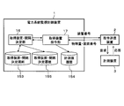
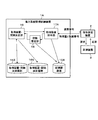
- FIG. 1 is a diagram illustrating a logical configuration of a power system monitoring and control device 1 according to the first embodiment. As shown in FIG. 1, the power system monitoring and control device 1 acquires measurement values at each point of the power system from the measurement device 3 by the command transmission device 2.
- the command transmission device 2 receives a number (hereinafter, device number) that uniquely identifies the measurement device 3 from the power system monitoring control device 1, and requests a physical quantity that is a measurement value from the measurement device 3 according to the device number. Is what you get.
- the physical quantity includes any of voltage, current, active power, and reactive power. By doing in this way, the power system monitoring and control apparatus 1 can flexibly monitor the power system based on any physical quantity.
- the command transmission device 2 transmits the device number and the power supply or the physical quantity on the line measured by the measurement device 3 corresponding to the device number to the power system monitoring control device 1.
- the measuring device 3 responds to the command transmitting device 2 with a physical quantity that is a measured value of each part of the power system in response to a request from the command transmitting device 2.
- the measuring device 3 can acquire the physical quantity on the track or the power source.
- the power system monitoring and control device 1 includes an acquisition device / interval determination unit 16 that is a processing unit, an acquisition device command unit 17, an acquisition device / interval determination rule 153 that is data, a measured value history 154, and an acquisition device / interval. And a determination history 155.
- the power system monitoring control device 1 transmits a device number to the command transmission device 2, and acquires the device number and a physical quantity on the power source or line measured by the measuring device 3 corresponding to the device number.
- the acquisition device / interval determination unit 16 determines a measurement condition according to the power supply acquired by the first measurement device and the physical quantity on the line based on the acquisition device / interval determination rule 153, and sends it to the acquisition device command unit 17. It is a processing unit to notify.
- the first measuring device is included in a plurality of measuring devices 3.
- the acquisition device / interval determination unit 16 determines a measurement condition and notifies the acquisition device command unit 17 in order to acquire a physical quantity at each point in the vicinity of the first measurement device.
- the measurement conditions are the selection of the second measurement device provided at each point in the vicinity of the first measurement device, the time interval for acquiring the measurement value from the second measurement device, and the measurement by the second measurement device. Contains value acquisition start order information.
- the second measuring devices are also one of the plurality of measuring devices 3.
- the power system monitoring and control device 1 limits the second measurement device that acquires the measurement value, or extends the time interval for acquiring the measurement value by the second measurement device. Can also monitor the power grid 6.
- the acquisition device / interval determination unit 16 further stores the determined measurement condition in the acquisition device / interval determination history 155. The acquisition device / interval determination process executed by the acquisition device / interval determination unit 16 will be described in detail with reference to FIG.
- the acquisition device command unit 17 is a processing unit that transmits a command including a device number to the command transmission device 2 based on the measurement condition notified from the acquisition device / interval determination unit 16.
- the acquisition device command unit 17 instructs the plurality of measurement devices 3 to acquire physical quantities on the line or the power source.
- the acquisition device command unit 17 acquires a physical quantity and a device number via the command transmission device 2.
- the acquisition device command unit 17 transmits the acquired physical quantity and device number to the acquisition device / interval determination unit 16 and stores them in the measurement value history 154.
- the acquisition device command process executed by the acquisition device command unit 17 will be described in detail with reference to FIG.
- the acquisition device / interval determination rule 153 is a database in which measurement condition determination rules are defined, and will be described in detail with reference to FIG.
- the measurement value history 154 is a database that stores the history of physical quantities on the power source and the line as measurement values, and will be described in detail with reference to FIG.
- the acquisition device / interval determination history 155 is a database that stores a history of measurement conditions determined by the acquisition device / interval determination unit 16. The configuration of the acquisition device / interval determination history 155 will be described in detail with reference to FIG.
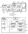
- FIG. 2 is a diagram illustrating a physical configuration of the power system monitoring control device 1 according to the first embodiment.
- the power system monitoring control device 1 is communicably connected to the command transmission device 2 and the measurement devices 3-1, 3-2, 3-3,.
- the communication path 9 is, for example, a wired LAN (Local Area Network) or a wireless LAN network, and connects the command transmission device 2, the measurement device 3, the power system monitoring control device 1, and the like.
- LAN Local Area Network
- the command transmission device 2 includes a communication interface 21, a CPU (Central Processing Unit) 22, a memory 23, and a storage device 25.
- the communication interface 21 is, for example, a wired LAN card or a wireless LAN card, and transmits and receives information to and from the measurement device 3 and the power system monitoring and control device 1 via the communication path 9.
- the CPU 22 is a central processing unit that executes various programs and controls the command transmission device 2 in an integrated manner.
- the CPU 22 is connected to each part of the command transmission device 2 by an internal bus.
- the memory 23 is, for example, a RAM (Random Access Memory), which reads and stores programs and data from the storage device 25, and temporarily stores information when the CPU 22 executes various programs.
- the storage device 25 is, for example, a hard disk or a flash memory, and stores information such as programs and data.
- the measuring devices 3-1, 3-2, 3-3,... Each include a receiving device 31 and a sensor 32.
- the measuring device 3 receives a request from the command transmitting device 2 by the receiving device 31, and measures a physical quantity on the power source or the line by the sensor 32.
- the measuring devices 3-1, 3-2, 3-3,... are not particularly distinguished, they may be simply referred to as the measuring device 3.
- the reception device 31 includes a communication interface 311, a CPU 312, a memory 313, and a storage device 315.
- the communication interface 311 is the same as the communication interface 21 of the command transmission device 2, and transmits and receives information to and from the command transmission device 2 and the power system monitoring control device 1 via the communication path 9.
- the CPU 312, the memory 313, and the storage device 315 are the same as the CPU 22, the memory 23, and the storage device 25 of the command transmission device 2, respectively.
- the sensor 32 is, for example, an ammeter, a voltmeter, a wattmeter, or the like, and measures a physical quantity such as a current, voltage, reactive power, or active power on a power supply or a line.
- the power system monitoring control device 1 includes a communication interface 11, a CPU 12, a memory 13, an output device 14, and a storage device 15.
- the output device 14 is, for example, a display device or a display lamp.
- the output device 14 displays output information of each program of the power system monitoring and control device 1 and data of each database, or the measurement device 3 acquired via the communication path 9. Display each output information.
- the output device 14 displays the contents of the acquisition device / interval determination history 155 to indicate the measurement device 3 that acquires the measurement value, the acquisition interval, the acquisition start order, and the determination reason for the administrator. Can be shown.
- the output device 14 can indicate the past state of the power system 6 to the administrator by displaying the content of the measurement value history 154, for example.
- the communication interface 11 is the same as the communication interface 21 of the command transmission device 2 and transmits / receives information to / from the command transmission device 2 and the measurement device 3 through the communication path 9.
- the CPU 12 and the memory 13 are the same as the CPU 22 and the memory 23 of the command transmission device 2, respectively.
- the storage device 15 is the same as the storage device 25 of the command transmission device 2, and further stores an acquisition device / interval determination program 151 and an acquisition device command program 152 as programs.
- the storage device 15 further stores an acquisition device / interval determination rule 153, a measurement value history 154, and an acquisition device / interval determination history 155 as data.
- the acquisition device / interval determination program 151 is read into the memory 13 and executed by the CPU 12 to implement the acquisition device / interval determination unit 16 (see FIG. 1).
- the acquisition device command program 152 is read into the memory 13 and executed by the CPU 12, thereby realizing the acquisition device command unit 17 (see FIG. 1).
- FIG. 3 is a diagram illustrating a configuration example of the power system 6 in the first embodiment.
- the power system 6 includes a distribution substation 4, measuring devices 3-0 to 3-7, solar power generation devices 5-1 and 5-2 (PV: Photovoltaics), and a load (not shown). And a line 61 connecting them.
- the power system 6 supplies power to a load (not shown).
- the distribution substation 4 converts the upper system voltage (not shown) into the voltage of the power system 6 and supplies the power.
- the measuring devices 3-0 to 3-7 measure physical quantities at each point of the power system 6.
- the measuring device 3-0 is assigned device number # 0.
- device numbers # 1 to # 7 are assigned to the measuring devices 3-1 to 3-7, respectively.
- the solar power generation devices 5-1 and 5-2 receive sunlight to generate electric power, and supply electric power in conjunction with the electric power system 6.
- the solar power generation devices 5-1 and 5-2 are not particularly distinguished, the solar power generation device 5 may be simply described.
- the command transmission device 2 and the power system monitoring control device 1 can communicate with each of the measurement devices 3-0 to 3-7 via the communication path 9.
- FIG. 3 shows that the measuring device 3-2 representing each measuring device 3 is connected to the command transmitting device 2 via the communication path 9.
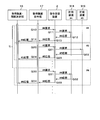
- FIG. 4 is a diagram illustrating the acquisition device / interval determination rule 153 according to the first embodiment.
- the acquisition device / interval determination rule 153 is a database in which rules for determining the measurement device 3 for acquiring a measurement value, its acquisition interval, and its acquisition start order are defined.
- the acquisition device / interval determination unit 16 acquires the measurement value based on the acquisition device / interval determination rule 153.
- the rule to be determined since the rule to be determined is configured as a database, it can be flexibly modified as compared with the case where it is configured by being incorporated in a program.
- the acquisition device / interval determination rule 153 includes a device number column 153a, a threshold value column 153b, an acquisition device number column 153c, an acquisition interval column 153d, and an acquisition start order column 153e as items.
- the device number column 153a stores a number that uniquely identifies the first measuring device for determining the threshold value related to the physical quantity.
- the measuring device 3-4 with device number # 4 is selected as the first measuring device.
- the first measurement device can appropriately grasp the state of the power system 6 by being provided at a power source that supplies power to the power system 6, a branch point of the line 61 of the power system 6, or the like.
- the threshold value field 153b stores a threshold condition relating to a physical quantity by the first measuring device.
- the acquisition device number column 153c stores a number that uniquely identifies the second measurement device for newly acquiring a measurement value.
- the second measuring device is a measuring device 3 that newly acquires a measured value when the physical quantity measured by the first measuring device satisfies the condition of the threshold value column 153b.
- the acquisition interval column 153d stores a time interval in acquiring the measurement value by the second measurement device.
- the acquisition start order column 153e stores the acquisition order of measurement values between the second measurement devices. By setting the acquisition order of the acquisition start order column 153e of any second measurement device high, the acquisition device command unit 17 (see FIG. 1) can measure the measured value at a more accurate timing from the second measurement device. Can be obtained.
- the determination rule of the measuring device 3 will be described. If the physical quantity by the first measuring device that regularly acquires the measured value is within the appropriate range, the purpose is to monitor the entire power system 6 widely, and from the second measuring device widely distributed over the entire power system 6 Get the measured value. At this time, the physical quantity at each point where the measurement value is not acquired is estimated and interpolated from the measurement values acquired at other points. The estimated value is inferior in accuracy to the measured value obtained by the measuring device 3. Examples of the estimation method include the method described in Non-Patent Document 2.
- the records in the second to ninth lines in FIG. 4 indicate that the measurement value (voltage) of the measuring device 3-4 with the device number # 4 is in the proper range (from 6400 to 6700).
- the record in the second line defines that measurement values are acquired from the measurement device 3 with the device number # 0 at a time interval of 60 seconds.
- the records on the 4th to 6th lines define that the measurement values are acquired at the time intervals of 60 seconds from the measurement devices 3 of the device numbers # 2 to # 4.
- the record on the ninth line defines that the measurement value is acquired from the measurement device 3 with the device number # 7 at a time interval of 60 seconds.
- the record on the 3rd line and the record on the 7th and 8th lines stipulate that the measurement values are not acquired from the measurement apparatuses 3 of the apparatus numbers # 1, # 5, and # 6.
- the acquisition interval “0” and the acquisition start order “ ⁇ ” mean that the measurement value is not acquired from the second measurement device.
- the physical quantity of the first measuring device 3-4 that regularly acquires measurement values is outside the appropriate range, it is necessary to monitor the vicinity of the first measuring device with high accuracy. Therefore, for each point in the vicinity of the first measurement device, a measurement value is frequently acquired from the second measurement device group that measures each point without using low-precision estimation or interpolation. Instead, the measurement value is acquired at a low frequency from the measurement device 3 existing in other locations.
- the records in the 10th to 17th lines in FIG. 4 indicate that the measurement value (voltage) of the measurement device 3-4 with the device number # 4 is a condition that deviates from the appropriate range (greater than 6700). .
- the records on the 10th to 17th lines frequently acquire measurement values from the second measurement device 3 group in the vicinity of the first measurement device 3-4, and the corresponding acquisition from the measurement device 3 existing at another point. It is stipulated to reduce.
- FIG. 5 is a diagram illustrating the measurement value history 154 according to the first embodiment.
- the measurement value history 154 is a database that manages the history of measurement values acquired by the acquisition device command unit 17.
- the measurement value history 154 includes a date / time column 154a, an acquisition device number column 154b, and a measurement value column 154c as items.
- the date and time column 154a stores the date and time when the acquisition device command unit 17 acquires the measurement value.
- the acquisition device number column 154b stores the device number of the measurement device 3 from which the acquisition device command unit 17 has acquired the measurement value.
- the measurement value (physical quantity) acquired by the acquisition device command unit 17 is stored in the measurement value column 154c.
- the second line indicates that the measured value 6530 was acquired from the measuring device 3-0 of device number # 0 at 8:00:00.
- the third line indicates that the measured value 6510 is acquired from the measuring device 3-2 of the device number # 2 at 18:00 after 1 second.
- the fourth line indicates that the measured value 6510 was acquired from the measuring device 3-3 with the device number # 3 at 18:00 after 1 second.
- the fifth line indicates that the measured value 6500 was acquired from the measuring device 3-4 of the device number # 4 at 8: 0: 3 after 1 second.
- the sixth line indicates that the measurement value 6480 was obtained from the measuring device 3-7 of device number # 7 at 8: 0: 4 after 1 second. That is, the second to sixth lines indicate that measurement values are acquired from each measurement device 3 in the order of the acquisition start order column 153e every second.
- the acquisition device command unit 17 acquires measurement values from each measurement device 3 in the order of the acquisition start order column 153e every predetermined time.
- the electric power system monitoring control apparatus 1 acquires the measured value from each 2nd measuring device for every predetermined time, even if it is the low-speed communication path 9, it can monitor the electric power system 6.
- FIG. Furthermore, the power system monitoring control device 1 can easily avoid the coincidence of the acquisition timings as shown in FIG. 10 to be described later by devising the value of the acquisition interval column 153d.
- the idea of the value in the acquisition interval field 153d is larger than the value (5 seconds) obtained by multiplying the number of selected second measuring devices (5 units) by a predetermined time (1 second), for example, as shown in FIG.
- the value (60 seconds) is used, and the acquisition interval field 153d of each record is unified with the 60 seconds.
- the present invention is not limited to this, and the idea of the value in the acquisition interval field 153d only needs to avoid the coincidence of acquisition timing.
- the least common multiple (10 seconds) of the value of the acquisition interval field 153d related to the selected second measuring device is larger than the value (5 seconds) obtained by multiplying the number of selected second measuring devices by the predetermined time. It may be.
- FIG. 6 is a diagram illustrating an acquisition device / interval determination history 155 according to the first embodiment.
- the acquisition device / interval determination history 155 is a database that manages the history determined by the acquisition device / interval determination unit 16.
- the acquisition device / interval determination history 155 includes a date / time column 155a, a determination device number column 155b, a determination physical quantity column 155c, a determination threshold value column 155d, an acquisition device number column 155e, an acquisition interval column 155f, and an acquisition start order column.
- 155g is included as an item.
- the date and time column 155a stores the date and time when the acquisition device / interval determination unit 16 determines the acquisition device and the acquisition interval.
- the determination device number column 155b stores a number that uniquely identifies the first measurement device.
- the physical quantity acquired by the first measuring device is stored in the determination physical quantity column 155c.
- the acquisition device / interval determination unit 16 determines an acquisition device, an acquisition interval, and the like based on the physical quantity acquired by the first measurement device.
- the threshold value condition is stored in the determination threshold value column 155d.
- the acquisition device / interval determination unit 16 determines the physical quantity acquired by the first measurement device based on the threshold condition.
- the acquisition device number column 155e stores a number that uniquely identifies the second measurement device.
- the acquisition device / interval determination unit 16 determines the second measurement device, registers the second measurement device in the acquisition device number field 155e, and further transmits it to the acquisition device command unit 17.
- the acquisition device command unit 17 newly acquires a measurement value from the second measurement device.
- the acquisition interval column 155f stores the acquisition interval of the second measuring device.
- the acquisition device / interval determination unit 16 determines the acquisition interval of the second measurement device, registers the acquisition interval in the acquisition interval column 155f, and transmits the acquisition interval to the acquisition device command unit 17.
- the acquisition device command unit 17 acquires a new measurement value from the second measurement device at the acquisition interval stored in the acquisition interval column 155f.
- the acquisition start order column 155g stores the acquisition order of measurement values between the second measurement devices.
- the acquisition device / interval determination unit 16 determines the acquisition order of the measurement values between the second measurement devices, registers the acquisition order in the acquisition start order field 155g, and further transmits it to the acquisition device command unit 17.
- the acquisition device command unit 17 acquires a new measurement value from the second measurement device in the acquisition order stored in the acquisition start order column 155g.
- the acquisition device / interval determination history 155 includes the acquisition start order column 155g, the acquisition order of measurement values between the second measurement devices can be confirmed later.
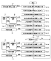
- FIG. 7 is a flowchart showing acquisition device command processing in the first embodiment.
- the acquisition device command unit 17 is embodied by the CPU 12 executing the acquisition device command program 152 and starts processing.
- the acquisition device command unit 17 receives from the acquisition device / interval determination unit 16 a combination of acquisition target devices including the device number for acquiring the measurement value, the acquisition interval, and the acquisition start order. (get. This triggers the acquisition device command process.
- the acquisition target device is a second measurement device.
- the acquisition device command unit 17 rearranges the received combinations of acquisition target devices in the order of acquisition start.
- the acquisition device command unit 17 repeats the process related to the acquisition target device.
- the acquisition device command unit 17 acquires the first measurement value from each acquisition target device in the order of acquisition start through these processes.
- the acquisition device command unit 17 transmits a device number related to the acquisition target device to the command transmission device 2.
- the command transmission device 2 transmits a measurement value request to the measurement device 3 related to the received device number, and receives the device number and the measurement value from the measurement device 3.
- step S ⁇ b> 14 the acquisition device command unit 17 receives the combination of the device number and the measured value from the command transmission device 2.
- the acquisition device command unit 17 can directly acquire the physical quantity at each point in the vicinity of the first measurement device by the acquisition target device, and thus can accurately measure the physical quantity.
- step S15 the acquisition device command unit 17 writes and registers the combination of the device number and the measured value in the measured value history 154.
- the manager of the power system 6 can later analyze the malfunction of the power system 6 based on the history at each point of the power system 6.
- step S ⁇ b> 16 the acquisition device command unit 17 transmits the combination of the device number and the measurement value to the acquisition device / interval determination unit 16.
- step S ⁇ b> 17 the acquisition device command unit 17 determines whether or not the processing related to the acquisition target device has been repeated. If the determination condition is not satisfied, the acquisition device command unit 17 returns to the process of step S12.
- step S ⁇ b> 18 the acquisition device command unit 17 determines whether the current time is the measurement timing of any acquisition target device based on the previous measurement value acquisition timing and acquisition interval of each acquisition target device. To do.
- the acquisition device command unit 17 repeats the process of step S18 if the determination condition is not satisfied, and performs the process of step S19 if the determination condition is satisfied.
- step S18 if the acquisition timings for the plurality of acquisition target devices coincide with each other, the acquisition device command unit 17 processes the one with the earlier acquisition start order first. Note that the processing in steps S19 to S22 shown below is the same as the processing in steps S13 to S16.
- step S ⁇ b> 19 the acquisition device command unit 17 transmits the device number of the acquisition target device to the command transmission device 2.
- the command transmission device 2 transmits a measurement value request to the measurement device 3 related to the received device number, and receives the device number and the measurement value from the measurement device 3.
- step S ⁇ b> 20 the acquisition device command unit 17 receives the combination of the device number and the measured value from the command transmission device 2.
- step S21 the acquisition device command unit 17 writes and registers the combination of the device number and the measured value in the measured value history 154.
- step S22 the acquisition device command unit 17 transmits the device number and the measured value to the acquisition device / interval determination unit 16, and the process returns to step S18.
- FIG. 8 is a diagram illustrating a sequence of acquisition device command processing in the first embodiment.
- # 4 surrounded by a broken line indicates a sequence related to the measuring device 3-4 of the device number # 4.
- # 5 surrounded by a broken line indicates a sequence related to the measuring device 3-5 having the device number # 5.
- the time interval Ti indicates the time interval at which the measuring device 3-4 with the device number # 4 acquires the physical quantity.
- the acquisition device command unit 17 transmits a request for the physical quantity of the measuring device 3-4 having the device number # 4 to the command transmission device 2.
- the measuring device 3-4 is a first measuring device.
- the command transmission device 2 transmits a request for a physical quantity to the measuring device 3-4 having a device number # 4.
- the measuring device 3-4 having the device number # 4 responds to the command transmitting device 2 with the physical quantity measured by the sensor 32.
- the command transmission device 2 responds to the acquisition device command unit 17 with the physical quantity measured by the measurement device 3-4 with the device number # 4.
- the acquisition device command unit 17 responds to the acquisition unit / interval determination unit 16 with the physical quantity measured by the measurement device 3-4 of device number # 4. Thereby, the acquisition device / interval determination unit 16 can acquire the physical quantity on the line or the power source measured by the first measurement device.
- the acquisition device command unit 17 transmits a request for the physical quantity of the measuring device 3-5 having the device number # 5 to the command transmission device 2.
- the measuring device 3-5 is a second measuring device.
- the command transmission device 2 transmits a request for a physical quantity to the measuring device 3-5 having a device number # 5.
- the measuring device 3-5 having the device number # 5 responds to the command transmitting device 2 with the measured physical quantity.
- sequence Q23 the command transmission device 2 responds to the acquisition device command unit 17 with the physical quantity measured by the measurement device 3-5 with the device number # 5.
- sequence Q24 the acquisition device command unit 17 responds to the acquisition unit / interval determination unit 16 with the physical quantity measured by the measurement device 3-5 with the device number # 5. Thereby, the acquisition device / interval determination unit 16 can acquire the physical quantity on the line or the power source measured by the second measurement device.
- the processes of sequences Q30 to Q34 are the same as the processes of sequences Q10 to Q14 described above.
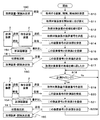
- FIG. 9 is a flowchart showing acquisition apparatus / interval determination processing in the first embodiment.
- the acquisition device / interval determination unit 16 is embodied by the CPU 12 executing the acquisition device / interval determination program 151 and starts processing.
- the acquisition device / interval determination unit 16 determines the measurement device 3 that acquires the measurement value, the acquisition interval, and the acquisition start order. Is transmitted to the acquisition device command unit 17.
- step S30 the acquisition device / interval determination unit 16 acquires (receives) from the acquisition device command unit 17 a combination of a device number that uniquely identifies the measurement device 3 and a physical quantity that is the measurement value. This triggers the acquisition device / interval determination process.
- the physical quantity that is a measurement value is a physical quantity on the line 61 if the measuring apparatus 3 is installed on the line 61, and a physical quantity of the power source if the measuring apparatus 3 is attached to the power source.
- step S31 the acquisition device / interval determination unit 16 reads the value in the device number field 153a of the record of the acquisition device / interval determination rule 153, and determines whether or not it is the same as the acquired device number.
- the acquisition device / interval determination unit 16 performs the process of step S32 if the determination condition is satisfied (Yes), and returns to the process of step S30 if the determination condition is not satisfied (No). If the determination condition in step S ⁇ b> 31 is satisfied, the acquisition device / interval determination unit 16 can acquire the physical quantity by the first measurement device of the measurement devices 3.
- step S32 the acquisition device / interval determination unit 16 reads the acquisition device / interval determination rule 153, and based on this, the second measurement device acquires a measurement value from the physical quantity acquired in step S30; The acquisition interval and the acquisition start order are determined. Specifically, the acquisition device / interval determination unit 16 searches the device number column 153a and the threshold value column 153b of the acquisition device / interval determination rule 153 using the device number acquired in step S30 and the measured value as keys. The acquisition device / interval determination unit 16 acquires a record in which the acquired device number matches the information in the device number column 153a and the acquired measurement value satisfies the condition of the threshold value column 153b.
- the acquisition device / interval determination unit 16 determines the combination of the acquisition device number column 153c, the acquisition interval column 153d, and the acquisition start order column 153e of this record, the second measurement device, its acquisition interval, and its acquisition start. Determine as order. That is, the acquisition device / interval determination unit 16 can select the second measurement device based on the physical quantity of the first measurement device, and can determine the time interval for acquiring the measurement values and the acquisition start order.
- the acquisition device / interval determination unit 16 acquires the records in the second to ninth lines in FIG.
- the second measuring device is determined.
- the combinations of (device number, acquisition interval, acquisition start order) of the determined second measuring devices are (# 0, 60, 1), (# 1,0,-), (# 2, 60, 2). , (# 3, 60, 3), (# 4, 60, 4), (# 5, 0,-), (# 6, 0,-), (# 7, 60, 5).
- the acquisition device / interval determination unit 16 acquires the records on lines 10 to 17 in FIG. Then, the second measuring device is determined.
- the combinations of (device number, acquisition interval, acquisition start order) of the determined second measuring devices are (# 0, 50, 5), (# 1, 0,-), (# 2, 0,-) , (# 3, 0,-), (# 4, 30, 1), (# 5, 30, 2), (# 6, 30, 3), (# 7, 30, 4).
- step S33 the acquisition device / interval determination unit 16 writes the device number for acquiring the measurement value, the acquisition interval, and the acquisition start order determined in step S32 in the acquisition device / interval determination history 155. And register. Further, the acquisition device / interval determination unit 16 writes the date and time determined in step S32 and the physical quantity and threshold used for the determination in the acquisition device / interval determination history 155 and registers them. Thereby, the administrator of this electric power grid
- step S32 when the combination of (device number, physical quantity) acquired in step S32 is (# 4, 6500), the acquisition device / interval determination unit 16 registers the records of lines 2 to 9 in FIG. Further, when the combination of (device number, physical quantity) acquired in step S32 is (# 4, 6750), the acquisition device / interval determination unit 16 registers the records on the 11th to 18th lines in FIG. In step S ⁇ b> 34, the acquisition device / interval determination unit 16 transmits the combination of the device number for acquiring the measurement value, the acquisition interval, and the acquisition start order determined in step S ⁇ b> 32 to the acquisition device command unit 17. To do. Thereby, the acquisition device / interval determination unit 16 can instruct the second measurement device by the acquisition device instruction unit 17. When the process of step S34 ends, the acquisition device / interval determination unit 16 returns to the process of step S30.
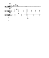
- FIG. 10 is a diagram showing coincidence of acquisition timings in the first embodiment.
- the horizontal direction on the right indicates a common time.
- the first line shows the measuring device 3-4 that is device number # 4.
- the circle on the line indicates the measurement value acquisition timing.
- the measuring device 3-4 acquires measurement values at a time interval of 30 seconds.
- the second line indicates the measuring device 3-5 that is device number # 5.
- the circle on the line indicates the measurement value acquisition timing.
- the measuring device 3-5 acquires the measurement value at a time interval of 30 seconds.
- the measuring devices 3-4 and 3-5 acquire measurement values at different timings.
- the third line indicates the measuring device 3-0 that is device number # 0.
- the circle on the line indicates the measurement value acquisition timing.
- the measuring device 3-0 acquires the measurement value at a time interval of 50 seconds, and the acquisition timings coincide at the time Tj.
- the acquisition device command unit 17 determines the acquisition order of the measurement values of both devices based on the acquisition start order of the measurement devices 3-0 and 3-5. For example, by setting the acquisition start order of the measurement device 3-0 higher, the acquisition device command unit 17 can acquire measurement values from the measurement device 3-0 at an accurate timing.
- the acquisition device / interval determination unit 16 of the first embodiment directly acquires a physical quantity from the acquisition device command unit 17 using the first measurement device.
- the acquisition device / interval determination unit 16 of the second embodiment acquires a physical quantity estimated and interpolated from the measurement values acquired by the measurement device 3 at another point.
- the device number column 153a in the records of the 2nd to 9th lines in FIG. 4 is “# 4” indicating the device number of the first measuring device 3-4.
- the device number column 153a in each of these records is “# 1” indicating the unacquired measurement device 3-1.
- the physical quantity of the measuring device 3-1 is estimated from other measured values and interpolated. The configuration and operation of the second embodiment will be specifically described below.
- FIG. 11 is a diagram showing a logical configuration of the power system monitoring control device 1A in the second embodiment.
- symbol is provided to the structure same as the electric power system monitoring control apparatus 1 of 1st Embodiment shown in FIG.
- the power system monitoring control device 1A of the second embodiment includes an acquisition device command unit 17A different from the acquisition device command unit 17 of the first embodiment, and further includes a state estimation unit 18. ing. Other than that, it is comprised similarly to the electric power system monitoring control apparatus 1 (refer FIG. 1) of 1st Embodiment.
- the acquisition device command unit 17A of the second embodiment transmits the physical quantity and device number acquired via the command transmission device 2 to the state estimation unit 18 and stores them in the measurement value history 154.
- the state estimation unit 18 estimates and interpolates the measurement values of the first measurement device from the measurement values acquired by the measurement device 3 at other points. Similarly, the state estimation unit 18 indirectly estimates and interpolates the physical quantity at each point near the first measurement device from the measurement value of the second measurement device acquired via the acquisition device command unit 17A. Is.
- the state estimation unit 18 transmits the estimated physical quantity at each point to the acquisition device / interval determination unit 16 and stores it in the measurement value history 154.
- the power system monitoring control device 1A can reduce the number of measurement devices 3 that acquire measurement values or extend the time interval of measurement value acquisition by the measurement devices 3, so that the communication path 9 can be operated at a lower speed. Even if it exists, the electric power grid
- FIG. 12 is a diagram illustrating a physical configuration of the power system monitoring and control apparatus 1A in the second embodiment.
- symbol is provided to the structure same as the electric power system monitoring control apparatus 1 of 1st Embodiment shown in FIG.
- the power system monitoring control device 1A of the second embodiment includes a storage device 15A that is different from the storage device 15 of the first embodiment.
- the storage device 15A of the second embodiment stores an acquisition device command program 152A different from the acquisition device command program 152 stored in the storage device 15 of the first embodiment, and further stores a state estimation program 156. .
- the same program and data as the storage device 15 (see FIG. 2) of the first embodiment are stored.
- the acquisition device command program 152A is read into the memory 13 and executed by the CPU 12, thereby realizing the acquisition device command unit 17A (see FIG. 11).
- the state estimation program 156 is read into the memory 13 and executed by the CPU 12 to implement the state estimation unit 18 (see FIG. 11).
- FIG. 13 is a flowchart showing acquisition device command processing in the second embodiment.
- the acquisition device command unit 17A of the second embodiment is implemented by the CPU 12 executing the acquisition device command program 152 and starts processing.
- the processing in steps S10 to S11 is the same as the processing in steps S10 to S11 shown in FIG.
- steps S12 to S15, S16A, and S17 the acquisition device command unit 17A repeats the process related to the acquisition target device.
- the acquisition device command unit 17A acquires the first measurement value from each acquisition target device in the acquisition start order by these processes.
- the processing in steps S13 to S15 is the same as the processing in steps S13 to S15 shown in FIG.
- step S16A the acquisition device command unit 17A transmits the combination of the device number and the measured value to the state estimation unit 18.
- step S17 the acquisition device command unit 17A determines whether or not the processing related to the acquisition target device has been repeated. If the determination condition is not satisfied, the acquisition device command unit 17A returns to the process of step S12.
- step S18 the acquisition device command unit 17A determines whether or not the current time is the measurement timing of any acquisition target device based on the previous measurement value acquisition timing and acquisition interval of each acquisition target device. To do.
- the acquisition device command unit 17A repeats the process of step S18 if the determination condition is not satisfied, and performs the process of step S19 if the determination condition is satisfied.
- step S18 if the acquisition timings for the plurality of acquisition target devices coincide with each other, the acquisition device command unit 17A processes the earlier acquisition start order first.
- the processes in steps S19 to S21 and S22A shown below are the same as the processes in steps S13 to S15 and S16A.
- steps S19 to S21 is further the same as the processing of steps S19 to S21 shown in FIG.
- step S22A the acquisition device command unit 17A transmits the device number and the measurement value to the state estimation unit 18, and the process returns to step S18.
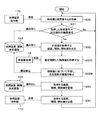
- FIG. 14 is a flowchart showing a state estimation process in the second embodiment.
- the state estimation unit 18 is embodied by the CPU 12 executing the state estimation program 156 and starts processing.
- the state estimation unit 18 acquires (receives) a combination of a device number that uniquely identifies the measurement device 3 and a physical quantity that is a measurement value from the acquisition device command unit 17A.
- the state estimation process is started.
- the state estimation unit 18 estimates a physical quantity at another point of the power system 6 from the acquired physical quantity and device number.
- the estimation method is, for example, the method described in Non-Patent Document 2.
- step S42 the state estimation unit 18 writes and registers the estimated and interpolated physical quantity in the measured value history 154.
- the state estimation unit 18 transmits the estimated and interpolated physical quantity to the acquisition device / interval determination unit 16, and returns to the process of step S40.
- the power system monitoring and control apparatus 1A can grasp the physical quantities at many points of the power system 6 without increasing the communication amount with each measuring device 3.
- FIG. 15 is a flowchart illustrating an acquisition apparatus / interval determination process according to the second embodiment.
- the acquisition device / interval determination unit 16 acquires, from the state estimation unit 18, a combination of the device number that uniquely identifies the measurement device 3 and the physical quantity that is the measurement value. (Receive). This triggers the acquisition device / interval determination process.
- the physical quantity that is a measurement value is a physical quantity on the line 61 if the measuring apparatus 3 is installed on the line 61, and a physical quantity of the power source if the measuring apparatus 3 is attached to the power source.
- steps S31 to S34 is the same as the processing of steps S31 to S34 (see FIG. 9) of the first embodiment.
- the acquisition device / interval determination unit 16 transmits the combination of the device number for acquiring the measurement value, the acquisition interval, and the acquisition start order to the acquisition device command unit 17A. Thereby, the acquisition device / interval determination unit 16 can instruct the second measurement device by the acquisition device instruction unit 17A.
- the acquisition device / interval determination unit 16 returns to the process of step S30.
- the state estimation unit 18 acquires and processes the physical quantity indirectly estimated from the measurement value of the second measurement device. Thereby, the number of the 2nd measuring devices which acquire a measurement value can be decreased, or the time interval of measurement value acquisition by the 2nd measuring device can be extended.
- the power system manager needs to set an optimal value in advance in the acquisition device / interval determination rule 153.
- accumulated data obtained by measuring the physical quantity of each point of the power system over a predetermined period is necessary. Therefore, the operation man-hour of the power system monitoring and control apparatus increases, and there is a possibility that a time lag until the start of operation occurs.
- the power system monitoring and control device dynamically optimizes the acquisition device / interval determination rule 153 by learning a threshold value indicating a normal range and an abnormal range of physical quantities, for example. Turn into. Thereby, the man-hour for calculating the optimum value set in the acquisition device / interval determination rule 153 becomes unnecessary, and the operation of the power system monitoring control device can be started quickly.
- the configuration and operation of the third embodiment will be specifically described below.
- FIG. 16 is a diagram showing a logical configuration of the power system monitoring control device 1B in the third embodiment.
- symbol is provided to the structure same as the electric power system monitoring control apparatus 1 of 1st Embodiment shown in FIG.
- the power system monitoring control device 1 ⁇ / b> B of the third embodiment includes an acquisition device / interval determination unit 16 ⁇ / b> B that is different from the acquisition device / interval determination unit 16 of the first embodiment. Other than that, it has the same configuration as the power system monitoring and control device 1 of the first embodiment.
- the acquisition device / interval determination unit 16B of the third embodiment has the same functions as those of the acquisition device / interval determination unit 16 of the first embodiment, and the normal range and abnormal range of the physical quantity based on the acquired physical quantity. And the function of correcting the threshold value of the acquisition device / interval determination rule 153 is provided.
- the acquisition device / interval determination process executed by the acquisition device / interval determination unit 16B will be described in detail with reference to FIG.
- FIG. 17 is a flowchart illustrating an acquisition apparatus / interval determination process according to the third embodiment. The same elements as those in the acquisition apparatus / interval determination process of the first embodiment shown in FIG. After the processing is started, the processing in steps S30 to S32 is the same as the processing in steps S30 to S32 of the first embodiment (see FIG. 9). When the process of step S32 ends, the acquisition device / interval determination unit 16B performs the process of step S32A.
- step S32A the acquisition device / interval determination unit 16B acquires (receives) a physical quantity from the measurement value history 154.
- the acquisition device / interval determination unit 16B can refer to the physical quantity of each point up to the present, and can improve the accuracy of the learning process described later, for example.
- the acquisition device / interval determination unit 16B performs the process of step S32B.
- step S32B the acquisition device / interval determination unit 16B learns the normal range and the abnormal range of the physical quantity on the line measured by the first measurement device based on the acquired physical quantity, and acquires the acquisition device / interval determination rule.
- the threshold value of 153 is corrected.
- the acquisition device / interval determination unit 16B can optimize the acquisition device / interval determination rule 153 and more appropriately determine whether the physical quantity measured by the first measurement device is normal.
- the acquisition device / interval determination unit 16B performs the process of step S33.
- the processes in steps S33 and S34 are the same as the processes in steps S33 and S34 of the first embodiment (see FIG. 9).
- the acquisition device / interval determination unit 16B returns to the process of step S30.
- the power system monitoring and control device 1B of the third embodiment dynamically optimizes the acquisition device / interval determination rule 153 by learning based on the physical quantity acquired from the measurement value history 154.
- the power system monitoring and control apparatus according to the modification of the third embodiment learns based on the physical quantity that is estimated by the state estimation unit 18 and dynamically optimizes the acquisition apparatus / interval determination rule 153.
- the configuration and operation of a modification of the third embodiment will be specifically described.
- FIG. 18 is a diagram illustrating a logical configuration of the power system monitoring control device 1C according to a modification of the third embodiment.
- symbol is provided to the structure same as 1 A of electric power system monitoring control apparatuses of 2nd Embodiment shown in FIG. 11, and the electric power system monitoring control apparatus 1B of 3rd Embodiment shown in FIG.
- the power system monitoring control device 1C according to the modification of the third embodiment includes an acquisition device / interval determination unit 16C similar to the acquisition device / interval determination unit 16B of the third embodiment, An acquisition device command unit 17C different from the acquisition device command unit 17 of the third embodiment is provided, and a state estimation unit 18 similar to that of the second embodiment is further provided.
- the acquisition device / interval determination unit 16C has a function of learning a normal range and an abnormal range of a physical quantity based on the acquired physical quantity and correcting a threshold value of the acquisition device / interval determination rule 153. I have.
- the acquisition device / interval determination process executed by the acquisition device / interval determination unit 16C will be described in detail with reference to FIG.
- the acquisition device command unit 17C of the modification of the third embodiment has the same function as the acquisition device command unit 17A of the second embodiment, and the physical quantity and device number acquired through the command transmission device 2 are obtained. While transmitting to the state estimation part 18 and the acquisition apparatus and space
- the acquisition device command unit 17C further directly transmits the acquired physical quantity and device number to the acquisition device / interval determination unit 16C.
- the acquisition device / interval determination unit 16C can quickly receive the physical quantity at each point of the power system 6 and determine the measurement device 3 that acquires the measurement value, the acquisition interval, and the like without delay. .
- the acquisition device command process executed by the acquisition device command unit 17C will be described in detail with reference to FIG.
- the state estimation unit 18 of the modification of the third embodiment has the same function as the state estimation unit 18 of the second embodiment, and performs the state estimation process shown in FIG.
- FIG. 19 is a flowchart illustrating an acquisition device command process according to a modification of the third embodiment.
- the acquisition device command unit 17C according to the modification of the third embodiment is embodied by the CPU 12 executing the acquisition device command program 152 and starts processing, as in the second embodiment.
- the processing in steps S10 to S11 is the same as the processing in steps S10 to S11 shown in FIG.
- steps S12 to S15, S16B, and S17 the acquisition device command unit 17C repeats the process related to the acquisition target device. With these processes, the acquisition device command unit 17C acquires the first measurement value from each acquisition target device in the acquisition start order.
- the processing in steps S13 to S15 is the same as the processing in steps S13 to S15 shown in FIG.
- step S16B the acquisition device command unit 17C transmits the combination of the device number and the measurement value to the state estimation unit 18 and the acquisition device / interval determination unit 16C.
- step S17 the acquisition device command unit 17C determines whether or not the processing related to the acquisition target device has been repeated. If the determination condition is not satisfied, the acquisition device command unit 17C returns to the process of step S12.
- step S18 the acquisition device command unit 17C determines whether the current time is the measurement timing of any acquisition target device based on the previous measurement value acquisition timing and acquisition interval of each acquisition target device. To do.
- the acquisition device command unit 17C repeats the process of step S18 if the determination condition is not satisfied, and performs the process of step S19 if the determination condition is satisfied.
- step S18 if the acquisition timings for the plurality of acquisition target devices coincide with each other, the acquisition device command unit 17C processes the earlier acquisition start order first. Note that the processes in steps S19 to S21 and S22B described below are the same as the processes in steps S13 to S15 and S16B.
- steps S19 to S21 is further the same as the processing of steps S19 to S21 shown in FIG.
- the acquisition device command unit 17C transmits the device number and the measured value to the state estimation unit 18 and the acquisition device / interval determination unit 16C, and the process returns to step S18.
- FIG. 20 is a flowchart illustrating an acquisition apparatus / interval determination process according to a modification of the third embodiment.
- the processing in steps S30 to S32 is the same as the processing in steps S30 to S32 (see FIG. 17) of the third embodiment.
- the acquisition device / interval determination unit 16C performs the process of step S32C.
- step S ⁇ b> 32 ⁇ / b> C the acquisition device / interval determination unit 16 ⁇ / b> C acquires (receives), from the state estimation unit 18, the physical quantity of another point estimated and interpolated by the state estimation unit 18. Accordingly, the acquisition device / interval determination unit 16C can acquire physical quantities at more points, and can improve the accuracy of the learning process.
- the acquisition device / interval determination unit 16C performs the process of step S32B.
- step S32B the acquisition device / interval determination unit 16C learns the normal range and the abnormal range of the physical quantity on the line measured by the first measurement device based on the acquired physical quantity, and acquires the acquisition device / interval determination rule. The threshold value of 153 is corrected.
- the acquisition device / interval determination unit 16C can optimize the acquisition device / interval determination rule 153 and more appropriately determine whether the physical quantity measured by the first measurement device is normal.
- the acquisition device / interval determination unit 16C performs the process of step S33.
- the processing in steps S33 and S34 is the same as the processing in steps S33 and S34 of the third embodiment (see FIG. 17).
- the acquisition device / interval determination unit 16C transmits the combination of the device number for acquiring the measurement value, the acquisition interval, and the acquisition start order to the acquisition device command unit 17C. Thereby, the acquisition device / interval determination unit 16C can instruct the second measurement device by the acquisition device instruction unit 17C.
- the acquisition device / interval determination unit 16C returns to the process of step S30.
- the present invention is not limited to the embodiments described above, and includes various modifications.
- the above-described embodiment has been described in detail for easy understanding of the present invention, and is not necessarily limited to the one having all the configurations described.
- a part of the configuration of one embodiment can be replaced with the configuration of another embodiment, and the configuration of another embodiment can be added to the configuration of one embodiment.
- the above-described configurations, functions, processing units, processing means, etc. may be partially or entirely realized by hardware such as an integrated circuit.
- Each of the above-described configurations, functions, and the like may be realized by software by a processor interpreting and executing a program that realizes each function.
- Information such as programs, tables, and files for realizing each function may be stored in a recording device such as a memory, a hard disk, an SSD (Solid State Drive), or a recording medium such as a flash memory card or a DVD (Digital Versatile Disk). it can.
- control lines and information lines indicate what is considered necessary for the explanation, and not all control lines and information lines on the product are necessarily shown. In practice, it may be considered that almost all the components are connected to each other. As modifications of the present invention, for example, there are the following (a) to (h).
- a power system monitoring control device 1 and a command transmission device 2 are provided.
- the present invention is not limited to this, and the command transmission device 2 may be integrated so as to have the function of the power system monitoring control device 1.
- the electric power system monitoring control apparatus 1 and the measuring device 3 are provided, respectively.
- the present invention is not limited to this, and the measuring device 3 may be integrated so as to have the function of the power system monitoring control device 1.
- a command transmission device 2 and a measurement device 3 are provided.
- the configuration is not limited to this, and the measurement device 3 may be integrated so as to have the function of the command transmission device 2.
- interval determination part 16 are based on the physical quantity on a track
- the acquisition device / interval determination unit 16 may determine the second measurement device that acquires the measurement value, the acquisition interval, and the acquisition start order based on the physical quantity of the power source.
- the power system monitoring and control device 1 determines whether or not it is a time zone in which the amount of power generated by the solar power generation device 5 is large based on the power generation value (measured value) or the predicted value (estimated value) of the solar power generation device 5. to decide.
- the power system monitoring control device 1 selects many of the measurement devices 3 in the vicinity of the photovoltaic power generation device 5 as the second measurement device, and shortens the acquisition interval. Furthermore, the power system monitoring control device 1 does not select the measurement device 3 in the vicinity where the solar power generation device 5 is not linked as the second measurement device, or lengthens the measurement value acquisition interval.
- the power system 6 includes a photovoltaic power generation device 5 as a distributed power source.
- the power system 6 is not limited to this, and the power system 6 may be, for example, a wind power generator, a solar power generator, a hydroelectric generator, a tidal power generator, a wave power generator, a sea current power generator, a biomass power generator, a geothermal power, as a distributed power source.
- a power generation device, a temperature difference utilization power generation device, or the like may be provided.
- the acquisition device / interval determination unit 16 includes a second measurement device that acquires a measurement value according to a static rule such as the acquisition device / interval determination rule 153, and the The acquisition interval and the acquisition start order were determined.
- the present invention is not limited to this, and the acquisition device / interval determination unit 16 includes a second measurement device that dynamically acquires measurement values from the measurement values required by the state estimation unit and the system control unit, and the acquisition interval thereof. And the acquisition start order may be determined.
- a state estimation means there exists the method described in the nonpatent literature 2, for example.
- the system control means for example, there is a method described in Non-Patent Document 3.
- the acquisition device / interval determination unit 16 evaluates the monitoring accuracy while repeating the acquisition device / interval determination processing, the acquisition device command processing, and the like, and by learning, the threshold field 153b of the acquisition device / interval determination rule 153 Alternatively, the value of each item such as the acquisition interval field 153d may be optimized.
- the measurement value that can be acquired by the measurement device 3 is one kind of physical quantity.
- the present invention is not limited to this, and the measurement values that can be acquired by the measurement device 3 may be a plurality of types of physical quantities.
- the power system monitoring and control apparatus 1 can grasp the state of the power system 6 more accurately.
- these plural types of physical quantities may be acquired collectively or may be acquired one by one in order. Thereby, the electric power system monitoring control apparatus 1 can select and acquire a required measured value.
Abstract
Description
更に電力系統制御手段として、例えば非特許文献3に示された方法がある。非特許文献3には、「本研究では、系統各地点の実時間の計測値を活用し、LRT,SVRの整定値をリアルタイムに補正する制御方式を提案する。」と記載されている。 The physical quantity at the point where the measurement value is not acquired can be estimated and interpolated from the measurement values acquired at other points. Non-Patent
Furthermore, as a power system control means, for example, there is a method disclosed in
そこで、本発明は、低速な通信環境であっても、系統構成や系統の物理量に応じて、電力系統監視制御で必要な電力系統の各点の計測値を取得することを可能とする電力系統監視制御装置および電力系統監視制御方法を提供することを課題とする。 According to the technology of Non-Patent
Therefore, the present invention provides a power system that can acquire measured values at each point of the power system necessary for power system monitoring control according to the system configuration and the physical quantity of the system, even in a low-speed communication environment. It is an object of the present invention to provide a monitoring control device and a power system monitoring control method.
その他の手段については、発明を実施するための形態のなかで説明する。 The power system monitoring control method of the present invention is executed by the power system monitoring control apparatus. The determining unit acquires the physical quantity by the first measuring apparatus among the plurality of measuring apparatuses, and selects the second measuring apparatus based on the physical quantity of the first measuring apparatus and acquires the measurement value The step of determining the interval, the step of instructing the second measuring device by the command unit, and the step of acquiring the physical quantity at each point in the vicinity of the first measuring device are executed.
Other means will be described in the embodiment for carrying out the invention.
(第1の実施形態)
図1は、第1の実施形態に於ける電力系統監視制御装置1の論理構成を示す図である。
図1に示すように、電力系統監視制御装置1は、指令送信装置2によって、計測装置3から、電力系統の各点の計測値を取得するものである。 Hereinafter, embodiments for carrying out the present invention will be described in detail with reference to the drawings.
(First embodiment)
FIG. 1 is a diagram illustrating a logical configuration of a power system monitoring and
As shown in FIG. 1, the power system monitoring and
取得装置・間隔決定部16が実行する取得装置・間隔決定処理は、図8で詳細に説明する。 The acquisition device /
The acquisition device / interval determination process executed by the acquisition device /
取得装置指令部17が実行する取得装置指令処理は、図7で詳細に説明する。 The acquisition
The acquisition device command process executed by the acquisition
計測値履歴154は、計測値である電源や線路上の物理量の履歴を格納するデータベースであり、図5で詳細に説明する。
取得装置・間隔決定履歴155は、取得装置・間隔決定部16が決定した計測条件の履歴を格納するデータベースである。取得装置・間隔決定履歴155の構成は、図6で詳細に説明する。 The acquisition device /
The
The acquisition device /
電力系統監視制御装置1は、通信路9を介して、指令送信装置2および計測装置3-1,3-2,3-3,…に通信可能に接続される。通信路9は、例えば有線LAN(Local Area Network)や無線LANのネットワークであり、指令送信装置2、計測装置3、電力系統監視制御装置1などを接続するものである。 FIG. 2 is a diagram illustrating a physical configuration of the power system monitoring
The power system monitoring
通信インタフェース21は、例えば有線LANカードや無線LANカードであり、通信路9を介して計測装置3や電力系統監視制御装置1と情報を送受信するものである。
CPU22は、中央処理装置であり、各種プログラムを実行して、この指令送信装置2を統括して制御するものである。CPU22は、内部バスによって指令送信装置2の各部に接続されている。 The
The
The
記憶装置25は、例えばハードディスクやフラッシュメモリであり、プログラムやデータなどの情報を記憶する装置である。 The
The
受信装置31は、指令送信装置2と同様に、通信インタフェース311と、CPU312と、メモリ313と、記憶装置315とを含んで構成される。
通信インタフェース311は、指令送信装置2の通信インタフェース21と同様であり、通信路9を介して指令送信装置2や電力系統監視制御装置1と情報を送受信するものである。
CPU312、メモリ313、記憶装置315は、それぞれ指令送信装置2のCPU22、メモリ23、記憶装置25と同様である。
センサ32は、例えば、電流計や電圧計や電力計などであり、電源や線路上の電流、電圧、無効電力、有効電力などの物理量を計測するものである。 The measuring devices 3-1, 3-2, 3-3,... Each include a receiving
Similarly to the
The
The
The
出力装置14は、例えば、ディスプレイ装置や表示用ランプであり、電力系統監視制御装置1の各プログラムの出力情報、各データベースのデータを表示したり、通信路9を介して取得した計測装置3の各出力情報を表示する。出力装置14は、例えば、取得装置・間隔決定履歴155の内容を表示することで、計測値を取得する計測装置3と、その取得間隔と、その取得開始順と、その決定理由とを管理者に示すことができる。出力装置14は、例えば計測値履歴154の内容を表示することで、この電力系統6の過去の状態を管理者に示すことができる。
通信インタフェース11は、指令送信装置2の通信インタフェース21と同様であり、通信路9を介して指令送信装置2や計測装置3と情報を送受信するものである。
CPU12、メモリ13は、それぞれ指令送信装置2のCPU22、メモリ23と同様である。 The power system monitoring
The
The
The
取得装置・間隔決定プログラム151は、CPU12によって、メモリ13に読み込まれて実行されることにより、取得装置・間隔決定部16(図1参照)が具現化される。
取得装置指令プログラム152は同様に、CPU12によって、メモリ13に読み込まれて実行されることにより、取得装置指令部17(図1参照)が具現化される。 The
The acquisition device /
Similarly, the acquisition
図3に示すように、電力系統6は、配電変電所4と、計測装置3-0~3-7と、太陽光発電装置5-1,5-2(PV:Photovoltaics)と、図示しない負荷と、これらを接続する線路61とを含んで構成される。電力系統6は、図示しない負荷に電力を供給するものである。
配電変電所4は、図示しない上位系統の電圧を、この電力系統6の電圧に変換して電力を供給するものである。 FIG. 3 is a diagram illustrating a configuration example of the
As shown in FIG. 3, the
The
太陽光発電装置5-1,5-2は、太陽光を受光して発電し、この電力系統6と連系して電力を供給するものである。以下、太陽光発電装置5-1,5-2を特に区別しないときには、単に太陽光発電装置5と記載している場合がある。
指令送信装置2および電力系統監視制御装置1は、通信路9を介して、各計測装置3-0~3-7と通信できる。なお、図3で、各計測装置3を代表して計測装置3-2が、通信路9を介して指令送信装置2と接続されていることを示している。 The measuring devices 3-0 to 3-7 measure physical quantities at each point of the
The solar power generation devices 5-1 and 5-2 receive sunlight to generate electric power, and supply electric power in conjunction with the
The
取得装置・間隔決定規則153は、計測値を取得する計測装置3と、その取得間隔と、その取得開始順とを決定する規則が定義されたデータベースである。取得装置・間隔決定部16は、この取得装置・間隔決定規則153に基づいて計測値を取得する。このように、決定する規則は、データベースとして構成されているので、プログラムに組み込まれて構成されている場合に比べて柔軟に修正可能である。
取得装置・間隔決定規則153は、装置番号欄153aと、閾値欄153bと、取得装置番号欄153cと、取得間隔欄153dと、取得開始順欄153eとを項目として含んでいる。 FIG. 4 is a diagram illustrating the acquisition device /
The acquisition device /
The acquisition device /
閾値欄153bには、第1の計測装置による物理量に関する閾値の条件が格納される。 The
The
取得開始順欄153eには、第2の計測装置間に於ける計測値の取得順番が格納される。いずれかの第2の計測装置の取得開始順欄153eの取得順番を高く設定することにより、取得装置指令部17(図1参照)は、その第2の計測装置から更に正確なタイミングで計測値を取得することができる。 The
The acquisition start
2行目のレコードは、装置番号#0の計測装置3から、60秒の時間間隔で計測値を取得することを定めている。4~6行目のレコードは、装置番号#2~#4の計測装置3から、それぞれ60秒の時間間隔で計測値を取得することを定めている。9行目のレコードは、装置番号#7の計測装置3から、60秒の時間間隔で計測値を取得することを定めている。 For example, the records in the second to ninth lines in FIG. 4 indicate that the measurement value (voltage) of the measuring device 3-4 with the
The record in the second line defines that measurement values are acquired from the
図5に示すように、計測値履歴154は、取得装置指令部17が取得した計測値の履歴を管理するデータベースである。
計測値履歴154は、日時欄154aと、取得装置番号欄154bと、計測値欄154cとを項目として含んでいる。
日時欄154aには、取得装置指令部17が計測値を取得した日時が格納される。
取得装置番号欄154bには、取得装置指令部17が計測値を取得した計測装置3の装置番号が格納される。
計測値欄154cには、取得装置指令部17が取得した計測値(物理量)が格納される。 FIG. 5 is a diagram illustrating the
As illustrated in FIG. 5, the
The
The date and
The acquisition
The measurement value (physical quantity) acquired by the acquisition
図6に示すように、取得装置・間隔決定履歴155は、取得装置・間隔決定部16が決定した履歴を管理するデータベースである。
取得装置・間隔決定履歴155は、日時欄155aと、判定装置番号欄155bと、判定物理量欄155cと、判定閾値欄155dと、取得装置番号欄155eと、取得間隔欄155fと、取得開始順欄155gとを項目として含んでいる。 FIG. 6 is a diagram illustrating an acquisition device /
As illustrated in FIG. 6, the acquisition device /
The acquisition device /
判定装置番号欄155bには、第1の計測装置を一意に特定する番号が格納される。
判定物理量欄155cには、この第1の計測装置により取得した物理量が格納される。取得装置・間隔決定部16は、この第1の計測装置により取得した物理量に基づき、取得装置や取得間隔などを決定する。 The date and
The determination
The physical quantity acquired by the first measuring device is stored in the determination
取得間隔欄155fには、第2の計測装置の取得間隔が格納される。取得装置・間隔決定部16は、第2の計測装置の取得間隔を決定して取得間隔欄155fに登録し、更に取得装置指令部17に送信する。取得装置指令部17は、取得間隔欄155fに格納された取得間隔で、この第2の計測装置から新たに計測値を取得する。
取得開始順欄155gには、第2の計測装置間に於ける計測値の取得順番が格納される。取得装置・間隔決定部16は、第2の計測装置間に於ける計測値の取得順番を決定して取得開始順欄155gに登録し、更に取得装置指令部17に送信する。取得装置指令部17は、取得開始順欄155gに格納された取得順番で、この第2の計測装置から新たに計測値を取得する。このように、取得装置・間隔決定履歴155は、取得開始順欄155gを含んでいるので、第2の計測装置間に於ける計測値の取得順番を事後的に確認することができる。 The acquisition
The
The acquisition start
取得装置指令部17は、CPU12が取得装置指令プログラム152を実行することによって具現化して、処理を開始する。
ステップS10に於いて、取得装置指令部17が、取得装置・間隔決定部16から、計測値を取得する装置番号と、その取得間隔と、その取得開始順とを含む取得対象装置の組合せを受信(取得)する。これを契機に、取得装置指令処理が開始される。ここで取得対象装置とは、第2の計測装置である。
ステップS11に於いて、取得装置指令部17は、受信した取得対象装置の組合せを、取得開始順に並び替える。 FIG. 7 is a flowchart showing acquisition device command processing in the first embodiment.
The acquisition
In step S <b> 10, the acquisition
In step S11, the acquisition
ステップS13に於いて、取得装置指令部17は、指令送信装置2に、この取得対象装置に関する装置番号を送信する。指令送信装置2は、受信した装置番号に係る計測装置3に計測値の要求を送信し、この計測装置3から装置番号と計測値とを受信する。 In steps S12 to S17, the acquisition
In step S <b> 13, the acquisition
ステップS15に於いて、取得装置指令部17は、計測値履歴154に、この装置番号と計測値との組合せを書き出して登録する。これにより、電力系統6の管理者は、電力系統6の各点に於ける履歴に基づいて、事後的に電力系統6の不具合などを解析することが可能となる。 In step S <b> 14, the acquisition
In step S15, the acquisition
ステップS17に於いて、取得装置指令部17は、取得対象装置に関する処理を繰り返したか否かを判断する。取得装置指令部17は、当該判断条件が成立しなかったならば、ステップS12の処理に戻る。 In step S <b> 16, the acquisition
In step S <b> 17, the acquisition
ステップS20に於いて、取得装置指令部17は、指令送信装置2から、この装置番号と計測値との組合せを受信する。
ステップS21に於いて、取得装置指令部17は、計測値履歴154に、この装置番号と計測値との組合せを書き出して登録する。
ステップS22に於いて、取得装置指令部17は、取得装置・間隔決定部16に、この装置番号と計測値とを送信し、ステップS18の処理に戻る。 In step S <b> 19, the acquisition
In step S <b> 20, the acquisition
In step S21, the acquisition
In step S22, the acquisition
破線で囲まれた#4は、装置番号#4の計測装置3-4に係るシーケンスを示している。破線で囲まれた#5は、同様に装置番号#5の計測装置3-5に係るシーケンスを示している。時間間隔Tiは、装置番号#4の計測装置3-4が物理量を取得する時間の間隔を示している。 FIG. 8 is a diagram illustrating a sequence of acquisition device command processing in the first embodiment.
# 4 surrounded by a broken line indicates a sequence related to the measuring device 3-4 of the
シーケンスQ11に於いて、指令送信装置2は、装置番号#4の計測装置3-4に対して、物理量の要求を送信する。
シーケンスQ12に於いて、装置番号#4の計測装置3-4は、指令送信装置2に対して、センサ32で測定した物理量を応答する。
シーケンスQ13に於いて、指令送信装置2は、取得装置指令部17に対して、装置番号#4の計測装置3-4が測定した物理量を応答する。
シーケンスQ14に於いて、取得装置指令部17は、取得装置・間隔決定部16に対して、装置番号#4の計測装置3-4が測定した物理量を応答する。これにより、取得装置・間隔決定部16は、第1の計測装置が測定した線路上または電源の物理量を取得することができる。 In sequence Q10, the acquisition
In sequence Q11, the
In the sequence Q12, the measuring device 3-4 having the
In sequence Q13, the
In sequence Q14, the acquisition
シーケンスQ21に於いて、指令送信装置2は、装置番号#5の計測装置3-5に対して、物理量の要求を送信する。
シーケンスQ22に於いて、装置番号#5の計測装置3-5は、指令送信装置2に対して、測定した物理量を応答する。 In sequence Q20, the acquisition
In sequence Q21, the
In the sequence Q22, the measuring device 3-5 having the
シーケンスQ24に於いて、取得装置指令部17は、取得装置・間隔決定部16に対して、装置番号#5の計測装置3-5が測定した物理量を応答する。これにより、取得装置・間隔決定部16は、第2の計測装置が測定した線路上または電源の物理量を取得することができる。
シーケンスQ30~Q34の処理は、上記したシーケンスQ10~Q14の処理と同様である。 In sequence Q23, the
In sequence Q24, the acquisition
The processes of sequences Q30 to Q34 are the same as the processes of sequences Q10 to Q14 described above.
取得装置・間隔決定部16は、CPU12が取得装置・間隔決定プログラム151を実行することによって具現化して処理を開始する。取得装置・間隔決定部16は、線路61上の物理量または電源の物理量が入力されたならば、計測値を取得する計測装置3と、その取得間隔と、その取得開始順とを決定し、それを取得装置指令部17に送信するものである。 FIG. 9 is a flowchart showing acquisition apparatus / interval determination processing in the first embodiment.
The acquisition device /
すなわち、取得装置・間隔決定部16は、第1の計測装置による物理量に基づいて第2の計測装置を選択すると共に、計測値取得の時間間隔および取得開始順を決定することができる。 In step S32, the acquisition device /
That is, the acquisition device /
ステップS34に於いて、取得装置・間隔決定部16は、ステップS32で決定した、計測値を取得する装置番号と、その取得間隔と、その取得開始順との組合せを取得装置指令部17に送信する。これにより、取得装置・間隔決定部16は、取得装置指令部17により第2の計測装置に対して指令することができる。取得装置・間隔決定部16は、ステップS34の処理が終了すると、ステップS30の処理に戻る。 For example, when the combination of (device number, physical quantity) acquired in step S32 is (# 4, 6500), the acquisition device /
In step S <b> 34, the acquisition device /
右横方向は、共通する時間を示している。最初の線は、装置番号#4である計測装置3-4を示している。線上の丸印は、計測値の取得タイミングを示している。計測装置3-4は、30秒の時間間隔で計測値を取得している。
2番目の線は、装置番号#5である計測装置3-5を示している。線上の丸印は、計測値の取得タイミングを示している。計測装置3-5は、30秒の時間間隔で計測値を取得している。計測装置3-4,3-5は、異なるタイミングで計測値を取得している。 FIG. 10 is a diagram showing coincidence of acquisition timings in the first embodiment.
The horizontal direction on the right indicates a common time. The first line shows the measuring device 3-4 that is
The second line indicates the measuring device 3-5 that is
第1の実施形態の取得装置・間隔決定部16は、取得装置指令部17から、第1の計測装置により物理量を直接取得している。これに対して、第2の実施形態の取得装置・間隔決定部16は、他点の計測装置3により取得した計測値から推定して補間した物理量を取得する。
第1の実施形態では、例えば、図4の2~9行目のレコードに於ける装置番号欄153aは、第1の計測装置3-4の装置番号を示す「#4」であった。しかし、第2の実施形態では、例えば、これら各レコードに於ける装置番号欄153aは、未取得の計測装置3-1を示す「#1」である。この計測装置3-1の物理量は、その他の計測値から推定されて補間される。以下、第2の実施形態の構成と動作とを具体的に説明する。 (Second Embodiment)
The acquisition device /
In the first embodiment, for example, the
図11に示すように、第2の実施形態の電力系統監視制御装置1Aは、第1の実施形態の取得装置指令部17とは異なる取得装置指令部17Aを備え、更に状態推定部18を備えている。それ以外は、第1の実施形態の電力系統監視制御装置1(図1参照)と同様に構成されている。 FIG. 11 is a diagram showing a logical configuration of the power system monitoring
As illustrated in FIG. 11, the power system monitoring
状態推定部18は、第1の計測装置の計測値を、他点の計測装置3により取得した計測値から推定して補間する。同様に状態推定部18は、第1の計測装置付近の各点に於ける物理量を、取得装置指令部17Aを介して取得した第2の計測装置の計測値から間接的に推定して補間するものである。状態推定部18は、推定した各点に於ける物理量を取得装置・間隔決定部16に送信すると共に、計測値履歴154に格納する。これにより、電力系統監視制御装置1Aは、計測値を取得する計測装置3の台数を減少させたり、計測装置3による計測値取得の時間間隔を延ばすことができるので、更に低速な通信路9であっても電力系統6を監視することができる。 The acquisition
The
図12に示すように、第2の実施形態の電力系統監視制御装置1Aは、第1の実施形態の記憶装置15とは異なる記憶装置15Aを備えている。
第2の実施形態の記憶装置15Aは、第1の実施形態の記憶装置15が格納する取得装置指令プログラム152とは異なる取得装置指令プログラム152Aを格納し、更に状態推定プログラム156を格納している。それ以外は、第1の実施形態の記憶装置15(図2参照)と同様のプログラムやデータを格納している。
取得装置指令プログラム152Aは、CPU12によって、メモリ13に読み込まれて実行されることにより、取得装置指令部17A(図11参照)が具現化される。
状態推定プログラム156は同様に、CPU12によって、メモリ13に読み込まれて実行されることにより、状態推定部18(図11参照)が具現化される。 FIG. 12 is a diagram illustrating a physical configuration of the power system monitoring and
As illustrated in FIG. 12, the power system monitoring
The
The acquisition
Similarly, the
第2の実施形態の取得装置指令部17Aは、第1の実施形態と同様に、CPU12が取得装置指令プログラム152を実行することによって具現化して、処理を開始する。
ステップS10~S11の処理は、図7に示すステップS10~S11の処理と同様である。
ステップS12~S15,S16A,S17に於いて、取得装置指令部17Aは、取得対象装置に関する処理を繰り返す。取得装置指令部17Aは、これらの処理によって、取得開始順に、各取得対象装置から最初の計測値を取得する。
ステップS13~S15の処理は、図7に示すステップS13~S15の処理と同様である。 FIG. 13 is a flowchart showing acquisition device command processing in the second embodiment. The same elements as those in the flowchart of the first embodiment shown in FIG.
As in the first embodiment, the acquisition
The processing in steps S10 to S11 is the same as the processing in steps S10 to S11 shown in FIG.
In steps S12 to S15, S16A, and S17, the acquisition
The processing in steps S13 to S15 is the same as the processing in steps S13 to S15 shown in FIG.
ステップS17に於いて、取得装置指令部17Aは、取得対象装置に関する処理を繰り返したか否かを判断する。取得装置指令部17Aは、当該判断条件が成立しなかったならば、ステップS12の処理に戻る。 In step S16A, the acquisition
In step S17, the acquisition
ステップS22Aに於いて、取得装置指令部17Aは、状態推定部18に、この装置番号と計測値とを送信し、ステップS18の処理に戻る。 The processing of steps S19 to S21 is further the same as the processing of steps S19 to S21 shown in FIG.
In step S22A, the acquisition
状態推定部18は、CPU12が状態推定プログラム156を実行することによって具現化して処理を開始する。
ステップS40に於いて、状態推定部18が、取得装置指令部17Aから、計測装置3を一意に特定する装置番号と、その計測値である物理量との組合せを取得(受信)する。これを契機に、状態推定処理が開始される。
ステップS41に於いて、状態推定部18は、取得した物理量と装置番号から電力系統6の他点の物理量を推定する。推定する方法とは、例えば、非特許文献2に記載された方法である。 FIG. 14 is a flowchart showing a state estimation process in the second embodiment.
The
In step S40, the
In step S41, the
ステップS43に於いて、状態推定部18は、推定して補間した物理量を、取得装置・間隔決定部16に送信し、ステップS40の処理に戻る。
これにより、電力系統監視制御装置1Aは、各計測装置3との間の通信量を増大させることなく、この電力系統6の多くの地点に於ける物理量を把握することができる。 In step S42, the
In step S43, the
As a result, the power system monitoring and
処理を開始した後、ステップS30Aに於いて、取得装置・間隔決定部16が、状態推定部18から、計測装置3を一意に特定する装置番号と、その計測値である物理量との組合せを取得(受信)する。これを契機に、取得装置・間隔決定処理は開始する。計測値である物理量は、計測装置3が線路61上に設置されるものであれば線路61上の物理量であり、計測装置3が電源に付属するものであれば電源の物理量である。
ステップS31~S34の処理は、第1の実施形態のステップS31~S34の処理(図9参照)と同様である。
ステップS34に於いて、取得装置・間隔決定部16は、計測値を取得する装置番号と、その取得間隔と、その取得開始順との組合せを取得装置指令部17Aに送信する。これにより、取得装置・間隔決定部16は、取得装置指令部17Aにより第2の計測装置に対して指令することができる。取得装置・間隔決定部16は、ステップS34の処理が終了すると、ステップS30の処理に戻る。 FIG. 15 is a flowchart illustrating an acquisition apparatus / interval determination process according to the second embodiment. The same elements as those in the acquisition apparatus / interval determination process of the first embodiment shown in FIG.
After starting the processing, in step S30A, the acquisition device /
The processing of steps S31 to S34 is the same as the processing of steps S31 to S34 (see FIG. 9) of the first embodiment.
In step S34, the acquisition device /
第1の実施形態に於いて、電力系統の管理者は、取得装置・間隔決定規則153に、予め最適値を設定する必要があった。取得装置・間隔決定規則153に設定する最適値を算出するためには、電力系統の各点の物理量を所定期間に亘って計測した蓄積データが必要である。よって、電力系統監視制御装置の運用工数が増大し、運用開始までのタイムラグが発生する虞がある。これに対して、第3の実施形態に於いて、電力系統監視制御装置は、例えば、物理量の正常範囲と異常範囲とを示す閾値の学習により、取得装置・間隔決定規則153を動的に最適化する。これにより、取得装置・間隔決定規則153に設定する最適値を算出する工数が不要となり、迅速に電力系統監視制御装置の運用を開始することができる。以下、第3の実施形態の構成と動作とを具体的に説明する。 (Third embodiment)
In the first embodiment, the power system manager needs to set an optimal value in advance in the acquisition device /
図16に示すように、第3の実施形態の電力系統監視制御装置1Bは、第1の実施形態の取得装置・間隔決定部16とは異なる取得装置・間隔決定部16Bを備えている。それ以外は、第1の実施形態の電力系統監視制御装置1と同一の構成を備えている。
第3の実施形態の取得装置・間隔決定部16Bは、第1の実施形態の取得装置・間隔決定部16と同様の機能に加えて、取得した物理量に基づいて物理量の正常範囲や異常範囲などを学習し、取得装置・間隔決定規則153の閾値を修正する機能を備えている。この取得装置・間隔決定部16Bが実行する取得装置・間隔決定処理は、図17で詳細に説明する。 FIG. 16 is a diagram showing a logical configuration of the power system monitoring
As illustrated in FIG. 16, the power system monitoring
The acquisition device /
処理を開始した後、ステップS30~S32の処理は、第1の実施形態のステップS30~S32の処理(図9参照)と同様である。ステップS32の処理を終了すると、取得装置・間隔決定部16Bは、ステップS32Aの処理を行う。 FIG. 17 is a flowchart illustrating an acquisition apparatus / interval determination process according to the third embodiment. The same elements as those in the acquisition apparatus / interval determination process of the first embodiment shown in FIG.
After the processing is started, the processing in steps S30 to S32 is the same as the processing in steps S30 to S32 of the first embodiment (see FIG. 9). When the process of step S32 ends, the acquisition device /
ステップS32Bに於いて、取得装置・間隔決定部16Bは、取得した物理量に基づいて第1の計測装置が計測する線路上の物理量の正常範囲や異常範囲などを学習し、取得装置・間隔決定規則153の閾値を修正する。これにより、取得装置・間隔決定部16Bは、取得装置・間隔決定規則153を最適化し、第1の計測装置が計測した物理量が正常であるか否かを、更に適切に判断することができる。ステップS32Bの処理を終了すると、取得装置・間隔決定部16Bは、ステップS33の処理を行う。
ステップS33,S34の処理は、第1の実施形態のステップS33,S34の処理(図9参照)と同様である。取得装置・間隔決定部16Bは、ステップS34の処理が終了すると、ステップS30の処理に戻る。 In step S32A, the acquisition device /
In step S32B, the acquisition device /
The processes in steps S33 and S34 are the same as the processes in steps S33 and S34 of the first embodiment (see FIG. 9). When the process of step S34 ends, the acquisition device /
第3の実施形態の電力系統監視制御装置1Bは、計測値履歴154から取得した物理量に基づく学習により、取得装置・間隔決定規則153を動的に最適化する。これに対して、第3の実施形態の変形例の電力系統監視制御装置は、状態推定部18が補間推定した物理量に基づいて学習し、取得装置・間隔決定規則153を動的に最適化する。以下、第3の実施形態の変形例の構成と動作とを具体的に説明する。 (Modification of the third embodiment)
The power system monitoring and
図18に示すように、第3の実施形態の変形例の電力系統監視制御装置1Cは、第3の実施形態の取得装置・間隔決定部16Bと同様な取得装置・間隔決定部16Cを備え、第3の実施形態の取得装置指令部17とは異なる取得装置指令部17Cを備え、更に第2の実施形態と同様な状態推定部18を備えている。
第3の実施形態の変形例の取得装置・間隔決定部16Cは、取得した物理量に基づいて物理量の正常範囲や異常範囲などを学習し、取得装置・間隔決定規則153の閾値を修正する機能を備えている。この取得装置・間隔決定部16Cが実行する取得装置・間隔決定処理は、図20で詳細に説明する。 FIG. 18 is a diagram illustrating a logical configuration of the power system monitoring
As illustrated in FIG. 18, the power system monitoring
The acquisition device /
この取得装置指令部17Cが実行する取得装置指令処理は、図19で詳細に説明する。
第3の実施形態の変形例の状態推定部18は、第2実施形態の状態推定部18と同一の機能を有し、図14に示す状態推定処理を行う。 The acquisition
The acquisition device command process executed by the acquisition
The
第3の実施形態の変形例の取得装置指令部17Cは、第2の実施形態と同様に、CPU12が取得装置指令プログラム152を実行することによって具現化して、処理を開始する。
ステップS10~S11の処理は、図13に示すステップS10~S11の処理と同様である。
ステップS12~S15,S16B,S17に於いて、取得装置指令部17Cは、取得対象装置に関する処理を繰り返す。取得装置指令部17Cは、これらの処理によって、取得開始順に、各取得対象装置から最初の計測値を取得する。
ステップS13~S15の処理は、図13に示すステップS13~S15の処理と同様である。 FIG. 19 is a flowchart illustrating an acquisition device command process according to a modification of the third embodiment. The same elements as those in the flowchart of the second embodiment shown in FIG.
The acquisition
The processing in steps S10 to S11 is the same as the processing in steps S10 to S11 shown in FIG.
In steps S12 to S15, S16B, and S17, the acquisition
The processing in steps S13 to S15 is the same as the processing in steps S13 to S15 shown in FIG.
ステップS17に於いて、取得装置指令部17Cは、取得対象装置に関する処理を繰り返したか否かを判断する。取得装置指令部17Cは、当該判断条件が成立しなかったならば、ステップS12の処理に戻る。 In step S16B, the acquisition
In step S17, the acquisition
ステップS22Bに於いて、取得装置指令部17Cは、状態推定部18および取得装置・間隔決定部16Cに、この装置番号と計測値とを送信し、ステップS18の処理に戻る。 The processing of steps S19 to S21 is further the same as the processing of steps S19 to S21 shown in FIG.
In step S22B, the acquisition
処理を開始した後、ステップS30~S32の処理は、第3の実施形態のステップS30~S32の処理(図17参照)と同様である。ステップS32の処理を終了すると、取得装置・間隔決定部16Cは、ステップS32Cの処理を行う。 FIG. 20 is a flowchart illustrating an acquisition apparatus / interval determination process according to a modification of the third embodiment. The same elements as those of the acquisition apparatus / interval determination process of the third embodiment shown in FIG.
After starting the processing, the processing in steps S30 to S32 is the same as the processing in steps S30 to S32 (see FIG. 17) of the third embodiment. When the process of step S32 ends, the acquisition device /
ステップS32Bに於いて、取得装置・間隔決定部16Cは、取得した物理量に基づいて第1の計測装置が計測する線路上の物理量の正常範囲や異常範囲などを学習し、取得装置・間隔決定規則153の閾値を修正する。これにより、取得装置・間隔決定部16Cは、取得装置・間隔決定規則153を最適化し、第1の計測装置が計測した物理量が正常であるか否かを、更に適切に判断することができる。ステップS32Bの処理を終了すると、取得装置・間隔決定部16Cは、ステップS33の処理を行う。
ステップS33,S34の処理は、第3の実施形態のステップS33,S34の処理(図17参照)と同様である。
ステップS34に於いて、取得装置・間隔決定部16Cは、計測値を取得する装置番号と、その取得間隔と、その取得開始順との組合せを取得装置指令部17Cに送信する。これにより、取得装置・間隔決定部16Cは、取得装置指令部17Cにより第2の計測装置に対して指令することができる。取得装置・間隔決定部16Cは、ステップS34の処理が終了すると、ステップS30の処理に戻る。 In step S <b> 32 </ b> C, the acquisition device /
In step S32B, the acquisition device /
The processing in steps S33 and S34 is the same as the processing in steps S33 and S34 of the third embodiment (see FIG. 17).
In step S34, the acquisition device /
本発明は上記した実施形態に限定されるものではなく、様々な変形例が含まれる。例えば上記した実施形態は、本発明を分かりやすく説明するために詳細に説明したものであり、必ずしも説明したすべての構成を備えるものに限定されるものではない。ある実施形態の構成の一部を他の実施形態の構成に置き換えることが可能であり、ある実施形態の構成に他の実施形態の構成を加えることも可能である。また、各実施形態の構成の一部について、他の構成の追加・削除・置換をすることも可能である。 (Modification)
The present invention is not limited to the embodiments described above, and includes various modifications. For example, the above-described embodiment has been described in detail for easy understanding of the present invention, and is not necessarily limited to the one having all the configurations described. A part of the configuration of one embodiment can be replaced with the configuration of another embodiment, and the configuration of another embodiment can be added to the configuration of one embodiment. Moreover, it is also possible to add, delete, and replace other configurations for a part of the configuration of each embodiment.
本発明の変形例として、例えば、次の(a)~(h)のようなものがある。 In each embodiment, the control lines and information lines indicate what is considered necessary for the explanation, and not all control lines and information lines on the product are necessarily shown. In practice, it may be considered that almost all the components are connected to each other.
As modifications of the present invention, for example, there are the following (a) to (h).
例えば、電力系統監視制御装置1は、太陽光発電装置5の発電値(計測値)または予測値(推定値)に基づき、太陽光発電装置5の発電量が多い時間帯であるか否かを判断する。この時間帯に於いて、電力系統監視制御装置1は、太陽光発電装置5が連系する付近の計測装置3の多くを、第2の計測装置として選択し、かつ、取得間隔を短くする。更に電力系統監視制御装置1は、太陽光発電装置5が連系しない付近の計測装置3を第2の計測装置としては選択しないか、または、計測値の取得間隔を長くする。 (D) In 1st Embodiment, the acquisition apparatus and the space |
For example, the power system monitoring and
11 通信インタフェース
12 CPU
13 メモリ
14 出力装置
15,15A 記憶装置
151 取得装置・間隔決定プログラム
152,152A 取得装置指令プログラム
153 取得装置・間隔決定規則
154 計測値履歴
155 取得装置・間隔決定履歴
156 状態推定プログラム
16,16B,16C 取得装置・間隔決定部 (決定部)
17,17A,17C 取得装置指令部 (指令部)
18 状態推定部
2 指令送信装置
21 通信インタフェース
22 CPU
23 メモリ
25 記憶装置
3,3-0~3-7 計測装置
3-4 第1の計測装置
3-0~3-7 第2の計測装置
31 受信装置
311 通信インタフェース
312 CPU
313 メモリ
315 記憶装置
32 センサ
4 配電変電所
5,5-1,5-2 太陽光発電装置
6 電力系統
61 線路
9 通信路 1, 1A, 1B, 1C Power system monitoring and
13
17, 17A, 17C Acquisition device command section (command section)
18
23
313
Claims (12)
- 複数の計測装置に対して線路上または電源の物理量の取得を指令する指令部と、
複数の前記計測装置のうちの第1の計測装置付近の各点に於ける物理量を取得するため、前記第1の計測装置により取得した物理量に基づいて第2の計測装置を選択し、当該第2の計測装置により計測値を取得する時間間隔を決定する決定部と、
を有することを特徴とする電力系統監視制御装置。 A command unit for commanding acquisition of physical quantities on a track or a power source for a plurality of measuring devices;
In order to acquire a physical quantity at each point in the vicinity of the first measuring apparatus among the plurality of measuring apparatuses, a second measuring apparatus is selected based on the physical quantity acquired by the first measuring apparatus, and the first A determination unit that determines a time interval at which the measurement value is acquired by the two measurement devices;
A power system monitoring and control apparatus comprising: - 前記計測装置により取得する物理量は、電圧、電流、有効電力、無効電力のいずれかを含む、
ことを特徴とする請求項1に記載の電力系統監視制御装置。 The physical quantity acquired by the measuring device includes any of voltage, current, active power, reactive power,
The power system monitoring and control apparatus according to claim 1. - 前記指令部は、前記第1の計測装置付近の各点に於ける物理量を、前記第2の計測装置により直接取得する、
ことを特徴とする請求項1に記載の電力系統監視制御装置。 The command unit directly obtains a physical quantity at each point in the vicinity of the first measuring device by the second measuring device;
The power system monitoring and control apparatus according to claim 1. - 前記第1の計測装置付近の各点に於ける物理量を、前記第2の計測装置により取得した計測値から間接的に推定する状態推定部、
を更に有することを特徴とする請求項1に記載の電力系統監視制御装置。 A state estimation unit that indirectly estimates a physical quantity at each point in the vicinity of the first measurement device from a measurement value acquired by the second measurement device;
The power system monitoring and control device according to claim 1, further comprising: - 情報を格納する記憶装置を更に有しており、
前記指令部は、前記第2の計測装置により取得した計測値の履歴を前記記憶装置に格納する、
ことを特徴とする請求項1に記載の電力系統監視制御装置。 A storage device for storing information;
The command unit stores a history of measurement values acquired by the second measurement device in the storage device.
The power system monitoring and control apparatus according to claim 1. - 前記決定部は、
前記第2の計測装置を選択し、当該第2の計測装置による計測値取得の時間間隔を決定した決定履歴を前記記憶装置に登録する、
ことを特徴とする請求項5に記載の電力系統監視制御装置。 The determination unit
Selecting the second measurement device and registering a determination history in which the time interval of measurement value acquisition by the second measurement device is determined in the storage device;
The power system monitoring and control apparatus according to claim 5. - 前記記憶装置は、前記第1の計測装置により取得した物理量に基づき、前記第2の計測装置を決定し、当該第2の計測装置による計測値取得の時間間隔を決定する決定規則を格納する、
ことを特徴とする請求項6に記載の電力系統監視制御装置。 The storage device determines the second measurement device based on the physical quantity acquired by the first measurement device, and stores a determination rule for determining a time interval of measurement value acquisition by the second measurement device.
The power system monitoring and control device according to claim 6. - 前記第2の計測装置により取得した計測値の履歴に基づいて、前記決定規則を最適化するように学習する、
ことを特徴とする、請求項7に記載の電力系統監視制御装置。 Learning to optimize the decision rule based on a history of measurement values acquired by the second measurement device;
The power system monitoring and control device according to claim 7, wherein - 線路上または電源の物理量を、前記計測装置により取得した計測値から間接的に推定する状態推定部を更に有し、
前記状態推定部が前記計測装置により取得した計測値から間接的に推定した物理量に基づいて、前記決定規則を最適化するように学習する、
ことを特徴とする、請求項7に記載の電力系統監視制御装置。 Further comprising a state estimation unit for indirectly estimating the physical quantity of the power source on the track or the power source from the measurement value acquired by the measurement device,
Learning to optimize the decision rule based on the physical quantity indirectly estimated from the measurement value acquired by the measurement device by the state estimation unit,
The power system monitoring and control device according to claim 7, wherein - 前記決定規則は更に、前記第2の計測装置による計測値の取得開始順情報を含む、
ことを特徴とする請求項7に記載の電力系統監視制御装置。 The determination rule further includes acquisition start order information of measurement values by the second measurement device,
The power system monitoring control device according to claim 7. - 前記決定履歴は更に、前記第2の計測装置による計測値の前記取得開始順情報を含む、
ことを特徴とする請求項10に記載の電力系統監視制御装置。 The determination history further includes the acquisition start order information of the measurement values by the second measurement device,
The power system monitoring and control device according to claim 10. - 計測装置に対して線路上または電源の物理量の取得を指令する指令部と、
計測値を取得する時間間隔を決定する決定部と、
を備える電力系統監視制御装置が実行する電力系統監視制御方法であって、
前記決定部は、
複数の前記計測装置のうちの第1の計測装置により物理量を取得するステップと、
前記第1の計測装置による物理量に基づいて第2の計測装置を選択すると共に計測値取得の時間間隔を決定するステップと、
前記指令部により前記第2の計測装置に対して指令するステップと、
前記第1の計測装置付近の各点に於ける物理量を取得するステップと、
を実行することを特徴とする電力系統監視制御方法。 A command unit for instructing the measurement device to acquire physical quantities on the track or power supply;
A determination unit for determining a time interval for acquiring measurement values;
A power system monitoring and control method executed by a power system monitoring and control apparatus comprising:
The determination unit
Obtaining a physical quantity by a first measuring device of the plurality of measuring devices;
Selecting a second measurement device based on a physical quantity by the first measurement device and determining a time interval for measurement value acquisition;
Commanding the second measuring device by the command unit;
Obtaining physical quantities at points near the first measuring device;
The power system monitoring control method characterized by performing.
Priority Applications (3)
| Application Number | Priority Date | Filing Date | Title |
|---|---|---|---|
| JP2015522438A JPWO2014203376A1 (en) | 2013-06-20 | 2013-06-20 | Power system monitoring control device and power system monitoring control method |
| US14/899,455 US20160146864A1 (en) | 2013-06-20 | 2013-06-20 | Power System Monitoring and Control Apparatus, and Power System Monitoring and Control Method |
| PCT/JP2013/066980 WO2014203376A1 (en) | 2013-06-20 | 2013-06-20 | Power system supervisory control apparatus and power system supervisory control method |
Applications Claiming Priority (1)
| Application Number | Priority Date | Filing Date | Title |
|---|---|---|---|
| PCT/JP2013/066980 WO2014203376A1 (en) | 2013-06-20 | 2013-06-20 | Power system supervisory control apparatus and power system supervisory control method |
Publications (1)
| Publication Number | Publication Date |
|---|---|
| WO2014203376A1 true WO2014203376A1 (en) | 2014-12-24 |
Family
ID=52104138
Family Applications (1)
| Application Number | Title | Priority Date | Filing Date |
|---|---|---|---|
| PCT/JP2013/066980 WO2014203376A1 (en) | 2013-06-20 | 2013-06-20 | Power system supervisory control apparatus and power system supervisory control method |
Country Status (3)
| Country | Link |
|---|---|
| US (1) | US20160146864A1 (en) |
| JP (1) | JPWO2014203376A1 (en) |
| WO (1) | WO2014203376A1 (en) |
Cited By (2)
| Publication number | Priority date | Publication date | Assignee | Title |
|---|---|---|---|---|
| CN105608213A (en) * | 2015-12-30 | 2016-05-25 | 南京国电南自电网自动化有限公司 | Interval copy method for tree structure object in intelligent substation configuration |
| JP2016178724A (en) * | 2015-03-18 | 2016-10-06 | 中国電力株式会社 | Power distribution system control device, control method for power distribution system control device, and program |
Families Citing this family (4)
| Publication number | Priority date | Publication date | Assignee | Title |
|---|---|---|---|---|
| WO2015151560A1 (en) * | 2014-03-31 | 2015-10-08 | 日本電気株式会社 | Monitoring device, monitoring system, monitoring method, and program |
| DE102015209588B3 (en) * | 2015-05-26 | 2016-10-06 | Lisa Dräxlmaier GmbH | Device and method for detecting faults in a vehicle electrical system |
| CN106788253B (en) * | 2017-01-19 | 2019-04-05 | 青海大学 | A kind of photovoltaic module voltage, current measure device |
| WO2022180787A1 (en) * | 2021-02-26 | 2022-09-01 | 三菱電機株式会社 | Voltage management device, voltage command device, power system monitoring system, measuring device, voltage management method, and voltage management program |
Citations (3)
| Publication number | Priority date | Publication date | Assignee | Title |
|---|---|---|---|---|
| JPS61221542A (en) * | 1985-03-27 | 1986-10-01 | 株式会社日立製作所 | Centralized monitor control system |
| JP2005004529A (en) * | 2003-06-12 | 2005-01-06 | Nippon Telegr & Teleph Corp <Ntt> | Environment monitoring system, and data collection device and data logger for use in this system |
| JP2007288877A (en) * | 2006-04-14 | 2007-11-01 | Hitachi Ltd | Power quality maintenance supporting method and system for power distribution system in linkage with a plurality of decentralized power sources |
Family Cites Families (5)
| Publication number | Priority date | Publication date | Assignee | Title |
|---|---|---|---|---|
| US8078418B2 (en) * | 2005-01-27 | 2011-12-13 | Electro Industries/Gauge Tech | Intelligent electronic device and method thereof |
| US9557723B2 (en) * | 2006-07-19 | 2017-01-31 | Power Analytics Corporation | Real-time predictive systems for intelligent energy monitoring and management of electrical power networks |
| US9331483B2 (en) * | 2009-12-17 | 2016-05-03 | Battelle Memorial Institute | Thermal energy storage apparatus, controllers and thermal energy storage control methods |
| EP2864736B1 (en) * | 2012-06-20 | 2022-08-17 | eTactica ehf. | Circuit branch measuring system |
| NO2701340T3 (en) * | 2012-08-21 | 2018-03-17 |
-
2013
- 2013-06-20 WO PCT/JP2013/066980 patent/WO2014203376A1/en active Application Filing
- 2013-06-20 US US14/899,455 patent/US20160146864A1/en not_active Abandoned
- 2013-06-20 JP JP2015522438A patent/JPWO2014203376A1/en active Pending
Patent Citations (3)
| Publication number | Priority date | Publication date | Assignee | Title |
|---|---|---|---|---|
| JPS61221542A (en) * | 1985-03-27 | 1986-10-01 | 株式会社日立製作所 | Centralized monitor control system |
| JP2005004529A (en) * | 2003-06-12 | 2005-01-06 | Nippon Telegr & Teleph Corp <Ntt> | Environment monitoring system, and data collection device and data logger for use in this system |
| JP2007288877A (en) * | 2006-04-14 | 2007-11-01 | Hitachi Ltd | Power quality maintenance supporting method and system for power distribution system in linkage with a plurality of decentralized power sources |
Cited By (2)
| Publication number | Priority date | Publication date | Assignee | Title |
|---|---|---|---|---|
| JP2016178724A (en) * | 2015-03-18 | 2016-10-06 | 中国電力株式会社 | Power distribution system control device, control method for power distribution system control device, and program |
| CN105608213A (en) * | 2015-12-30 | 2016-05-25 | 南京国电南自电网自动化有限公司 | Interval copy method for tree structure object in intelligent substation configuration |
Also Published As
| Publication number | Publication date |
|---|---|
| US20160146864A1 (en) | 2016-05-26 |
| JPWO2014203376A1 (en) | 2017-02-23 |
Similar Documents
| Publication | Publication Date | Title |
|---|---|---|
| WO2014203376A1 (en) | Power system supervisory control apparatus and power system supervisory control method | |
| Yao et al. | A fast load control system based on mobile distribution-level phasor measurement unit | |
| Tastu et al. | Spatio‐temporal analysis and modeling of short‐term wind power forecast errors | |
| JP5312611B2 (en) | Method and system for reducing feeder circuit losses using demand response | |
| Kezunovic et al. | The big picture: Smart research for large-scale integrated smart grid solutions | |
| JP6575939B2 (en) | System and method for analyzing vibration stability in a power transmission system | |
| US9127963B2 (en) | Selection of bellwether smart grid meters | |
| WO2015130439A1 (en) | Contingency-based load shedding | |
| WO2015130438A1 (en) | Power system management | |
| KR102482043B1 (en) | Method And Apparatus for Predicting Cooling Load in Small Scale Data | |
| KR102194271B1 (en) | Sunlight generation integrated management system based on model and method thereof | |
| JP5923454B2 (en) | Power system management apparatus and method | |
| Vanfretti et al. | A phasor measurement unit based fast real-time oscillation detection application for monitoring wind-farm-to-grid sub–synchronous dynamics | |
| JP2015148934A (en) | Power generation amount prediction device and power generation amount prediction method | |
| CN103155331A (en) | Method and device for producing a state signal | |
| JP6677396B2 (en) | Power usage prediction system and method | |
| CN110445171A (en) | A kind of active power and frequency control method and system based on the soft lineal system of marine wind electric field | |
| JP6005318B2 (en) | Power generation amount evaluation apparatus, power generation amount evaluation method, and power generation amount evaluation program | |
| JP2021529502A (en) | Technology for optimizing power grids by distributed forecasting | |
| JP7300893B2 (en) | Solar power generation output estimation device, solar power generation output estimation method, and solar power generation output estimation program | |
| Hwas et al. | Nonlinear observer-based fault detection and isolation for wind turbines | |
| Kunzemann et al. | Application of CPS within wind energy—current implementation and future potential | |
| US20200081424A1 (en) | Method and system for automatic selection of physical quantity measurements | |
| Amiri et al. | A novel optimal PMU location method in smart grids | |
| Dinh et al. | Implementation of Digital Twin-Assisted Condition Monitoring and Fault Diagnosis for Wind Turbines |
Legal Events
| Date | Code | Title | Description |
|---|---|---|---|
| 121 | Ep: the epo has been informed by wipo that ep was designated in this application |
Ref document number: 13887555 Country of ref document: EP Kind code of ref document: A1 |
|
| ENP | Entry into the national phase |
Ref document number: 2015522438 Country of ref document: JP Kind code of ref document: A |
|
| WWE | Wipo information: entry into national phase |
Ref document number: 14899455 Country of ref document: US |
|
| NENP | Non-entry into the national phase |
Ref country code: DE |
|
| 122 | Ep: pct application non-entry in european phase |
Ref document number: 13887555 Country of ref document: EP Kind code of ref document: A1 |