WO2014199692A1 - ネットワーク疎通確認装置、ネットワーク疎通確認方法及びネットワーク疎通確認プログラム - Google Patents
ネットワーク疎通確認装置、ネットワーク疎通確認方法及びネットワーク疎通確認プログラム Download PDFInfo
- Publication number
- WO2014199692A1 WO2014199692A1 PCT/JP2014/057051 JP2014057051W WO2014199692A1 WO 2014199692 A1 WO2014199692 A1 WO 2014199692A1 JP 2014057051 W JP2014057051 W JP 2014057051W WO 2014199692 A1 WO2014199692 A1 WO 2014199692A1
- Authority
- WO
- WIPO (PCT)
- Prior art keywords
- communication confirmation
- communication
- operation node
- established
- packet
- Prior art date
- Legal status (The legal status is an assumption and is not a legal conclusion. Google has not performed a legal analysis and makes no representation as to the accuracy of the status listed.)
- Ceased
Links
Images




Classifications
-
- H—ELECTRICITY
- H04—ELECTRIC COMMUNICATION TECHNIQUE
- H04L—TRANSMISSION OF DIGITAL INFORMATION, e.g. TELEGRAPHIC COMMUNICATION
- H04L12/00—Data switching networks
- H04L12/28—Data switching networks characterised by path configuration, e.g. LAN [Local Area Networks] or WAN [Wide Area Networks]
- H04L12/46—Interconnection of networks
- H04L12/4604—LAN interconnection over a backbone network, e.g. Internet, Frame Relay
- H04L12/462—LAN interconnection over a bridge based backbone
- H04L12/4625—Single bridge functionality, e.g. connection of two networks over a single bridge
-
- H—ELECTRICITY
- H04—ELECTRIC COMMUNICATION TECHNIQUE
- H04L—TRANSMISSION OF DIGITAL INFORMATION, e.g. TELEGRAPHIC COMMUNICATION
- H04L12/00—Data switching networks
- H04L12/64—Hybrid switching systems
- H04L12/6418—Hybrid transport
Definitions
- the present invention relates to a network communication confirmation device, a network communication confirmation method, and a network communication confirmation program for confirming communication in a network.
- a local area network is constructed in each of a plurality of bases, and the plurality of local area networks are further connected by a global network such as the Internet.
- the communication confirmation is performed for the segment of the local area network at each base.
- the segment is a subnetwork to which the operation node belongs.
- An operation node is a node that communicates with other operation nodes, a master node, and the like.
- a communication check node When conducting such communication check, generally, a communication check node is brought into each of a plurality of local area networks, and a communication test is performed using a technique such as Ping. In addition, it is also common to monitor the communication confirmation status of multiple bases by connecting the communication confirmation nodes of each base to a remote host via the Internet etc., and the remote host remotely operating the communication confirmation node. .
- a technique described in Patent Document 1 can be cited.
- a monitoring terminal transmits a trace route command to each terminal, and detects a router by returning response information to each router on a delivery route.
- each router determines whether or not the status of each router is normal depending on whether or not a response to the Ping command is returned from the router that transmits the Ping command to the detected router that is the router that returned the response information Monitor.
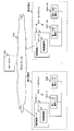
- FIG. 1 is a diagram illustrating an example of a general network communication confirmation system as a whole.
- the remote host 500 and the plurality of segments 600-i are connected to each other via the network 700.
- i which is segment identification information, may be omitted.
- the remote host 500 is a device having at least a function of remotely operating each of the communication confirmation nodes 610.
- Each of the segments 600 includes a communication confirmation node 610 and operation nodes 621 to 62N.
- the segment 600 is a sub-network that interconnects the communication confirmation node 610 and the operation nodes 621 to 62N, is installed at each different base, and is separated at each base.
- the communication confirmation node 610 includes: A communication confirmation unit 611-1 for confirming communication of the segment 600 is included.
- the operation nodes 621 to 62N may be any device that can communicate with the communication confirmation node 610, and are not particularly limited.
- the communication confirmation unit 611 includes a communication confirmation packet generation unit 611-1, a communication confirmation packet transmission / reception unit 611-2, a communication confirmation determination unit 611-3, and a communication confirmation information table 611-4.
- the communication confirmation packet generation unit 611-1 has a function of generating a communication confirmation packet.
- the communication confirmation packet transmission / reception unit 611-2 transmits the communication confirmation packet generated by the communication confirmation packet generation unit 611-1 to the operation nodes 621 to 62N.
- the operation nodes 621 to 62N that have received the communication confirmation packet transmit a communication confirmation response packet to the communication confirmation unit 611 as a response to the received communication confirmation packet.
- the communication confirmation packet transmitting / receiving unit 611-2 has a function of receiving the communication confirmation response packet.
- the communication confirmation determination unit 611-3 performs communication confirmation. A specific method for confirming communication will be described later.
- the communication confirmation information table 611-4 holds communication confirmation information which is information including a result of the communication confirmation together with information used when the communication confirmation is performed.
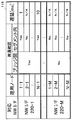
- FIG. 3 is a diagram illustrating a specific example of the communication confirmation information table 611-4.
- the communication confirmation information table 611-4 is provided with “communication confirmation” as an item indicating a communication confirmation result of each operation node.
- the communication confirmation packet transmitting / receiving unit 611-2 transmits the communication confirmation packet from the remote host 500, the communication confirmation packet transmitting / receiving unit 611-2 transmits the communication confirmation response packet.
- a “delay” indicating an elapsed time until reception is provided as an item.
- FIG. 4 is a diagram illustrating an example of the hardware configuration of the communication confirmation node 610.
- the communication confirmation node 610 includes a CPU 610-1, a communication control unit 610-2, a memory 610-3, a first network interface unit 610-4, and a second network interface unit 610-. 5 is included.
- the “network interface unit” is referred to as “NW I / F unit” as appropriate in the drawings, including the diagrams related to the embodiments of the present invention described below.
- the CPU 610-1 and the memory 610-3 are connected to the communication control unit 610-2 that is a device for executing communication.
- Each functional block included in the communication confirmation unit 611 described above performs arithmetic processing by the CPU 610-1 according to a program stored in a storage device such as the memory 610-3 or another memory (not shown). This is realized by controlling each hardware included in the communication confirmation node 610 according to the calculation processing result.
- the first network interface unit 610-4 is a network interface unit for connecting the communication confirmation node 610 to the remote host 500.
- the second network interface unit 610-5 is a network interface unit for connecting the communication confirmation node 610 to the operation nodes 621 to 62N in the segment 600.
- the general network communication confirmation system configured as described above operates as follows.
- the remote host 500 connects to each communication confirmation node 610 via the first network interface unit 610-4. Then, when the remote host 500 performs a remote operation, the communication confirmation unit 611 of each communication confirmation node 610 is operated.
- the communication confirmation packet generation unit 611-1 of each communication confirmation unit 611 confirms communication with the operation nodes 621 to 62N in the segment 600 to which the communication confirmation node 610 including the communication confirmation packet generation unit 611-1 itself belongs.
- a communication confirmation packet (for example, a Ping echo request packet) is generated. Then, the generated communication confirmation packet is transmitted to the communication confirmation packet transmitting / receiving unit 611-2.
- the communication confirmation packet transmission / reception unit 611-2 receives the communication confirmation packet received from the communication confirmation packet generation unit 611-1 from the second network interface unit 610 connected to the segment 600 corresponding to the IP address described in the packet header. Send to -5. At this time, a communication confirmation packet timer for measuring the time when the communication confirmation packet is transmitted is started.
- the second network interface unit 610-5 sends the communication confirmation packet to any of the operation nodes 621 to 62N that are operation nodes corresponding to the IP address described in the packet header received from the communication confirmation packet transmitting / receiving unit 611-2. Send.
- any of the operation nodes 621 to 62N which are operation nodes to which the communication confirmation packet is transmitted, receives the communication confirmation packet, it transmits a communication confirmation response packet (for example, a Ping echo reply packet) to the communication confirmation node 610. To do.
- a communication confirmation response packet for example, a Ping echo reply packet
- the communication confirmation packet transmission / reception unit 611-2 When the communication confirmation packet transmission / reception unit 611-2 receives this communication confirmation response packet, it stops the communication confirmation packet timer. Then, the communication confirmation packet transmission / reception unit 611-2 sends the communication confirmation response packet and information indicating the elapsed time from the transmission of the communication confirmation packet to the reception of the communication confirmation response packet to the communication confirmation determination unit 611-3. Send.
- the communication confirmation determination unit 611-3 receives the communication confirmation response packet and information indicating the elapsed time. Further, in response to the return of the communication confirmation response packet, the communication confirmation determining unit 611-3 updates information on the operation node that has transmitted the communication confirmation packet in the communication confirmation information table 611-4.
- the communication confirmation determining unit 611-3 updates the information of the operation node that has transmitted the communication confirmation packet in the communication confirmation information table 611-4.
- the general technique as described above it is possible to check the communication of the operation nodes 621 to 62N included in each segment 600 of each base.
- the general technique as described above has a plurality of problems as described below.
- the first problem is that in the general network monitoring system described above, the system becomes complicated as the number of bases to be monitored increases.
- the second problem is that, in the above-described general network monitoring system, the possibility of a software failure in the entire system increases with an increase in the number of monitoring sites.
- the reason is that an OS (Operating System) and a communication confirmation program need to operate on all communication confirmation nodes installed at each base.
- a network communication confirmation device capable of preventing the system from becoming complicated and preventing the occurrence of a software failure on the system. It is an object to provide a network communication confirmation method and a network communication confirmation program.
- a communication confirmation apparatus connected to one or more segments via a computer bus network, wherein at least one segment included in the one or more segments is included in the segment. Whether or not one or more operation nodes included can communicate with the communication confirmation device, and whether communication is established between the downstream bridge provided in the segment including the operation node and the upstream bridge provided in the communication confirmation device.
- a communication confirmation packet having the operation node as a transmission destination, a communication confirmation response packet that is a response packet to the communication confirmation packet, an upstream bridge provided in the communication confirmation device, and a downstream bridge provided in the segment including the operation node.
- Traffic checking device is provided, characterized in that it comprises a communication confirming means for confirming with.
- a communication confirmation method performed by a communication confirmation apparatus connected to one or more segments via a computer bus network, wherein at least one segment included in the one or more segments.
- a communication confirmation apparatus connected to one or more segments via a computer bus network, wherein at least one segment included in the one or more segments.
- Whether or not communication is established is determined in the segment including the operation node, the communication confirmation packet with the operation node as the transmission destination, the communication confirmation response packet that is a response packet to the communication confirmation packet, the upstream bridge provided in the communication confirmation device, and the segment including the operation node.
- Send / receive between bridges to determine whether communication is possible with the downstream bridge Traffic checking method characterized by having a communication confirmation step of confirming with the order of the packets is provided.
- a communication confirmation program for causing a computer to function as a communication confirmation device connected to one or more segments via a computer bus network, the computer comprising the one or more computers. For at least one segment included in the segment, whether or not one or more operation nodes included in the segment can communicate with the communication confirmation device, and a downstream bridge included in the segment including the operation node and the communication confirmation Whether or not communication is established with an upstream bridge provided in the apparatus, a communication confirmation packet having the operation node as a transmission destination, a communication confirmation response packet that is a response packet to the communication confirmation packet, and an upstream bridge provided in the communication confirmation apparatus , Downstream block of the segment including the operation node Communication confirmation program for causing to function whether communication between the Tsu di is taken as communication confirming means for confirming with a packet for transmitting and receiving between the bridge is provided.
- the present invention even when the number of bases to be monitored increases, it is possible to prevent the system from becoming complicated and to prevent the occurrence of a software failure on the system.
- surface which shows an example of the communication confirmation information table which the communication confirmation part by embodiment of this invention holds.
- the present embodiment is a communication confirmation device 800 that is connected to one or more segments 900 via a computer bus network 1000, and is included in the one or more segments 900.
- the downstream bridge 910 included in the segment including the operation node 920 and the communication Whether or not communication is established with the upstream bridge 820 provided in the confirmation device, a communication confirmation packet with the operation node 920 as a transmission destination and a communication confirmation response packet 1001 which is a response packet thereto, and the communication confirmation device.
- the upstream bridge 820 and the operation node 92 Including a communication confirmation means 810 for confirming whether or not communication is established with the downstream bridge 910 provided in the segment 900 including a packet 1002 for transmission / reception between the bridges. 800.
- FIG. 6 is a block diagram showing an example of the configuration of the communication confirmation system as the entire embodiment of the present invention.
- the present embodiment includes a communication confirmation node 100 and a plurality (or a single) segment 200.
- the communication confirmation node 100 and the plurality of segments 200 are connected via the computer bus network 300.
- the computer bus network 300 corresponds to a technique called ExpEther (Express Ether) (registered trademark) as described in Patent Document 2, for example.
- ExpEther is a PCI Express that allows a computer resource connected to a computer via Ethernet (registered trademark) to be used as a computer resource compatible with PCI Express. This is a technology related to over Ether. More specifically, ExpEther refers to, for example, a PCI Express board (functioning as an upstream bridge) connected to a PCI Express bus of a computer and a PCI Express board (as a downstream bridge) connected to a PCI Express bus of an expansion device. The PCI Express device connected to the PCI Express bus of the expansion device can be used as a computer resource by communicating with a predetermined protocol on the Ethernet between both boards. This is the technology that I did.
- the communication confirmation node 100 performs communication confirmation for each segment 200 provided at each site via the computer bus network 300.
- the communication confirmation node 100 includes a communication confirmation unit 110 and an upstream bridge 120 as functional blocks for executing the communication confirmation. Further, the upstream bridge 120 includes a communication monitoring unit 121.
- the communication confirmation unit 110 generates a communication confirmation packet for performing communication confirmation, and performs communication confirmation by transmitting and receiving the communication confirmation packet.
- the upstream bridge 120 realizes communication with each segment 200 via the computer bus network 300.
- the communication monitoring unit 121 acquires information for the communication confirmation unit 110 to perform communication confirmation by monitoring communication via the computer bus network 300.
- Each segment 200 includes a downstream bridge 210, a network interface unit 220, and a plurality (or a single) of operation nodes 231 to 23N.
- segment 200 is a sub-network that interconnects the operation nodes 231-1 to 23N-M, is installed at each different base, and is separated at each base.
- the downstream bridge 210 is connected to the communication confirmation node 100 via the computer bus network 300.
- the network interface unit 220 is an interface for the operation nodes 231-1 to 23N-M to connect to the computer bus network 300 via the downstream bridge 210.
- the network interface unit 220 is a LAN adapter (NIC: also called Network Interface Card) connected to the PCI Express bus. That is, the network interface unit 220 and the operation nodes 231 to 23N connected to the network interface unit 220 are connected by Ethernet to construct a LAN.
- NIC Network Interface Card
- the operation nodes 231-1 to 23N-M are nodes for which communication confirmation is performed by the communication confirmation node 100.
- the operation nodes 231-1 to 23N-M are devices having a function of communicating with the communication confirmation unit 110 via the upstream bridge 120, the downstream bridge 210, the network interface unit 220, and the computer bus network 300. Any device may be used.
- the communication confirmation packet generated by the communication confirmation node 100 is transmitted to the operation nodes 231-1 to 23N-M via the upstream bridge 120, the computer bus network 300, the downstream bridge 210, and the network interface unit 220.
- the operation nodes 231-1 to 23N-M that have received the communication confirmation packet generate a communication confirmation response packet as a response to the received communication confirmation packet, and send the generated communication confirmation response packet to the communication confirmation node 100.
- the communication confirmation node 100 receives this communication confirmation response packet.
- FIG. 7 is a functional block diagram showing in detail an example of a functional block realized by cooperation of hardware and software included in the communication confirmation node 100 of the present invention.
- the functional blocks included in will be described.
- the communication confirmation unit 110 includes a communication confirmation packet generation unit 111, a communication confirmation packet transmission / reception unit 112, a communication confirmation determination unit 113, a network interface registration unit 114, and a communication confirmation information table 115.
- the communication confirmation determination unit 113 includes an inter-bridge communication confirmation determination unit 113-1, and an intra-segment communication confirmation determination unit 113-2.
- the communication confirmation packet generator 111 has a function of generating a communication confirmation packet.
- the communication confirmation packet transmitting / receiving unit 112 has a function of transmitting / receiving a communication confirmation packet.
- the communication confirmation determining unit 113 has a function of determining communication confirmation with the operation nodes 231-1 to 23N-M to be monitored. More specifically, the inter-bridge communication confirmation determination unit 113-1 determines communication confirmation between the upstream bridge 120 and the downstream bridge 210. This means that communication between the bridges is confirmed. On the other hand, the intra-segment communication confirmation determining unit 113-2 executes the internal communication confirmation of each of the segments 200-1 to 200-M. That is, communication is confirmed between the downstream bridge 210 and the operation nodes 231-1 to 23N-M in the communication path via the network interface 220-1.
- the intra-segment communication confirmation determining unit 113-2 performs communication confirmation between the downstream bridge 210 and the operation nodes 231-1 to 23N-M in the communication path via the network interface 220-1. That is, the internal communication confirmation of each of the segments 200-1 to 200-M is performed.
- the network interface registration unit 114 monitors whether or not a new network interface unit 220 has been newly connected.
- the network interface registration unit 114 registers the newly connected network interface unit 220 in the communication confirmation information table 115 when the new network interface unit 220 is newly connected.
- the communication confirmation information table 115 is a table for managing the determination result of the communication confirmation by the communication confirmation determination unit 113.
- the communication confirmation information table 115 will be described with reference to FIG. 8 showing an example of the contents of the communication confirmation information table 115 included in the communication confirmation unit 110.
- the communication confirmation information table 115 is provided with “corresponding network interface” which is an item indicating the network interface unit 220 managed by the communication confirmation information table 115 as an item.
- the network interface unit 220 managed by the communication confirmation information table 115 is the network interface unit 220 to be monitored by the communication confirmation node 100.
- operation node that is an item indicating the operation nodes 231 to 23N connected to the network interface unit 220 described in the corresponding network interface item is provided as an item.
- between communication confirmation bridges which is an item indicating a communication confirmation result between the downstream bridge 210 and the upstream bridge 120 connected to the network interface unit 220 described in the corresponding network interface item. Is provided as an item.
- Between communication check bridges indicates whether communication is established between the upstream bridge provided in the communication check device and the downstream bridge provided in the segment including the operation node.
- the communication confirmation information table 115 an item indicating the result of confirming the connection between the operation nodes 231 to 23N described in the item of the operation node and the network interface unit 220 in the same segment 200 as the operation nodes 231 to 23N. “In the communication confirmation segment” is provided as an item. “In the communication confirmation segment” indicates whether or not communication is established between the operation node and the downstream bridge in the segment including the operation node.
- a delay time from when the communication confirmation unit 110 transmits the communication confirmation packet to when the communication confirmation response packet is received from the operation nodes 231 to 23N described in the operation node item is displayed. “Delay” which is an item to be shown is provided as an item.
- the communication confirmation node 100 includes a CPU 101, a root complex 102, a memory 103, and an upstream bridge 120.
- the upstream bridge 120 is connected to the computer bus network 300.
- this hardware configuration example is a PCI Express (registered trademark) standard, which is a standard standardized by PCI-SIG (PCI Special Interest Group) for communication by the communication confirmation node 100 as an example of a specific communication method. It is an example of a hardware configuration when it is assumed that it is performed in conformity with the above.
- PCI Express registered trademark
- PCI-SIG PCI Special Interest Group
- the communication confirmation node 100 includes a root complex 102 located at the top of the tree structure of the PCI Express standard.
- a CPU 101 is connected to the root complex 102 via a system bus, and a memory 103 is connected via a memory bus.
- Each functional block included in the communication confirmation unit 110 described above performs arithmetic processing by the CPU 101 according to a program unique to the present embodiment stored in a storage device such as the memory 103 or another memory (not shown). This is realized by controlling each hardware included in the communication confirmation node 100 according to the calculation processing result.
- each network interface unit 220 functions as a network interface unit included in the communication confirmation node 100 by the cooperation of the upstream bridge 120 and each downstream bridge 210.
- the above-described ExpEther technique is used.
- the communication confirmation unit 110 when the communication confirmation unit 110 is realized by a program and hardware, it is sufficient to incorporate a program unique to the present embodiment into only one communication confirmation node 100. This makes it possible to adopt a simple system configuration even when the number of bases monitored by the network monitoring system increases.
- the communication monitoring unit 121 monitors packet transmission / reception status. There are two types of packets to be monitored. The first is a packet generated by the root complex 102 and transmitted from the root complex 102 to the computer bus network 300. The other is a packet received via the computer bus network 300. The communication monitoring unit 121 monitors transmission / reception of these packets.
- the first method measures the time until a response packet is returned when a packet that is generated by the route complex 102 and requires a response packet to the packet to be transmitted is transmitted from the route complex 102. This is a method of detecting when the timer expires.
- Another method is a method in which the upstream bridge 120 and the downstream bridge 210 transmit an inter-bridge connection monitoring packet for periodically monitoring the connection.
- a packet that is generated by the route complex 102 and requires a response packet is used.
- a packet that requires a response packet refers to, for example, memory read access or configuration access that conforms to the PCI Express standard.
- the communication monitoring unit 121 saves the sequence number of the packet and starts a timer.
- the communication monitoring unit 121 stops the timer and transmits the response packet to the route complex 102.
- the communication monitoring unit 121 recognizes that the connection with the downstream bridge 210 that is the transmission target of the packet in which the timer has expired is disconnected when the timer expires for a certain period of time, and the communication monitoring unit 121
- the downstream bridge 210 to be disconnected is described in the register of (1).
- This method uses bridge identification information.
- the bridge identification information is information for identifying each bridge, and is generated by assigning a predetermined ID, for example.
- the communication monitoring unit 121 and each communication monitoring unit 211 periodically connect the bridges that describe the bridge identification information of the bridge including the communication monitoring unit 121 and each communication monitoring unit 211 itself with respect to other bridges. Send monitoring packets. Transmission is performed by broadcast, for example.
- the communication monitoring unit 121 in the upstream bridge 120 acquires bridge identification information when the downstream bridge 210 is connected to the upstream bridge 120. That is, the communication monitoring unit 121 in the upstream bridge 120 registers the bridge identification information of all the downstream bridges 210 connected to the upstream bridge 120.
- the communication monitoring unit 121 in the upstream bridge 120 receives the inter-bridge connection monitoring packet from the downstream bridge 210, the communication monitoring unit 121 refers to the bridge identification information described in the packet.
- the communication confirmation unit 110 can grasp that the connection with the certain downstream bridge 210 is disconnected.
- the network interface registration unit 114 registers each network interface unit 220 to be monitored by the communication confirmation unit 110 and registers each operation node 231 to 23N monitored by the network interface unit 220.
- the network interface registration unit 114 connects the new network interface 220 to the communication confirmation node 100 when a new network interface unit 220 to be monitored while the communication confirmation unit 110 is operating is newly connected. New connection target. Further, the network interface registration unit 114 registers the operation nodes 231 to 23N included in the segment 200 to which the newly connected network interface unit 220 is connected as a new monitoring target.
- the registration of the operation nodes 231 to 23N may be performed by a method in which a network communication confirmer inputs a new connection, or the operation nodes 231 to 23N to be added to the communication confirmation software are registered in advance. You may take a method.
- the communication confirmation packet generator 111 generates communication confirmation packets for the operation nodes 231 to 23N registered by the network interface registration unit 114.
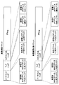
- FIG. 10 is a diagram showing the communication confirmation packet and the communication confirmation response packet.
- the communication confirmation packet and the communication confirmation response packet include three headers.
- the main body is a Ping packet.
- the Ethernet header includes the MAC address of the downstream bridge 210 as the transmission destination MAC address and the MAC address of the upstream bridge 120 as the transmission source MAC address.
- the TLP (Transaction Layer Packet) header includes the address of the downstream bridge 210 as a transmission destination address and the address of the upstream bridge 120 as a transmission source address.
- the address information used in the TLP header can be, for example, address information conforming to PCI Express.
- the intra-segment header includes the IP addresses of the operation nodes 231-1 to 23N-M as the transmission destination IP address, and the IP address of the network interface unit 220 as the transmission source IP address.
- the Ethernet header includes the MAC address of the downstream bridge 210 as the source MAC address and the MAC address of the upstream bridge 120 as the destination MAC address.
- the TLP header includes the address of the downstream bridge 210 as a transmission source address and the address of the upstream bridge 120 as a destination address.
- the intra-segment header includes the IP addresses of the operation nodes 231-1 to 23N-M as the source IP address, and the IP address of the network interface unit 220 as the destination IP address.
- the packet generated by the communication confirmation packet generator 111 includes, for example, the Ethernet header, the MAC address of the downstream bridge 210 of the segment to which the operation node to be monitored as the transmission destination MAC address belongs, and the upstream bridge as the transmission source MAC address.
- the MAC address of 120 is the TLP header, the address of the downstream bridge 210 of the segment to which the operation node to be monitored this time belongs as the destination address, the address of the upstream bridge 120 as the source address, and the A Ping packet in which the IP address of the current monitoring target operating node is described as the destination IP address, and the IP address of the network interface unit 220 of the segment to which the current monitoring target operating node belongs is described as the transmission source IP address. Generated.
- the communication confirmation packet generating unit 111 transmits the generated communication confirmation packet to the communication confirmation packet transmitting / receiving unit 112.
- the communication confirmation packet transmission / reception unit 112 When the communication confirmation packet transmission / reception unit 112 receives the communication confirmation packet from the communication confirmation packet generation unit 111, the communication confirmation packet transmission / reception unit 112 starts a timer and transmits the received communication confirmation packet to the computer bus network 300.
- the communication confirmation packet transmission / reception unit 112 when the communication confirmation packet transmission / reception unit 112 receives a communication confirmation response packet for the transmitted communication confirmation packet, the communication confirmation packet transmission / reception unit 112 stops the timer, and at least the transmission destination described in the intra-segment header in the communication confirmation response packet information The communication confirmation determining unit 113 is notified of the IP address of the transmission source and the fact that the timer has not expired.
- the communication confirmation packet transmitting / receiving unit 112 is described in the intra-segment header described in the transmitted communication confirmation packet when the timer expires without receiving the communication confirmation response packet and the timer expires.
- the communication confirmation determining unit 113 is notified of the destination and source IP addresses, the address specifying the downstream bridge 210 described in the TLP header or Ethernet header, and the fact that the timer has expired.
- the communication confirmation determining unit 113 updates the communication confirmation information table 115 based on the notification information from the communication confirmation packet transmitting / receiving unit 112.
- the communication confirmation determination unit 113 is an inter-bridge communication confirmation determination unit 113-1, which performs communication determination between the upstream bridge 120 and the downstream bridge 210, and an intra-segment communication confirmation determination, which performs communication determination between the network interface and the operation node. Part 113-2.
- the inter-bridge communication confirmation determining unit 113-1 receives the communication confirmation response packet for the communication confirmation packet from the communication confirmation packet transmitting / receiving unit 112, the communication confirmation packet is described in the transmission destination IP address of the intra-segment header of the communication confirmation response packet. It is determined that the downstream bridge 210 connected to the network interface unit 220 is connected, and the information is transmitted to the communication confirmation information table 115. That is, “Yes” is described in the item “between communication confirmation bridges” for the downstream bridge 210 that is the current determination target of the communication confirmation information table 115.
- the network interface unit described in the transmission source of the intra-segment header of the communication confirmation packet is referred to by referring to the information described in the register in the communication monitoring unit 121. Get the connection status of the bridge.
- the inter-bridge communication confirmation determining unit 113-1 sets “ No "is described.
- the inter-bridge communication confirmation determining unit 113-1 sets “Yes” to the item “between communication confirmation bridges” for the downstream bridge 210 as the current determination target in the communication confirmation information table 115. Is described.
- the intra-segment communication confirmation determining unit 113-2 receives a communication confirmation response packet for the communication confirmation packet from the communication confirmation packet transmitting / receiving unit 112, it is described in the transmission source IP address in the segment header of the communication confirmation response packet. It is determined that the operation nodes 231 to 23N can communicate with each other, and the communication confirmation table 115 is updated. That is, “Yes” is described in the item “within the communication confirmation segment” for the operation nodes 231 to 23N that are the current determination targets of the communication confirmation information table 115.
- the intra-segment communication confirmation determining unit 113-2 communicates with the operation nodes 231 to 23N described in the transmission destination of the communication confirmation packet.
- the communication confirmation information table 115 is updated by determining that it is impossible. That is, “No” is described in the item “within communication check segment” for the operation nodes 231 to 23N that are the current determination targets of the communication check information table 115.
- the communication confirmation information table 115 shows the continuity of all pairs of the upstream bridge 120 and the downstream bridge 210, the network interface 220, and the operation nodes 231 to 23N monitored by the communication confirmation program, and delays from transmission to reception of the communication confirmation packet. Possess. This information is updated by the communication confirmation determination unit 113.
- the communication confirmation packet generation unit 111 generates a communication confirmation packet to be transmitted to the communication confirmation packet transmission target operation node registered in the network interface registration unit 114. Then, the communication confirmation packet transmitting / receiving unit 112 transmits the generated packet to the designated network interface unit 220.
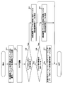
- the route complex 102 receives a command for transmitting a communication confirmation packet to the network interface unit 220 described above, and generates and transmits a packet to the network interface unit 220 (step S1).
- the packet transmitting / receiving unit starts a timer corresponding to the transmission source IP address and the transmission destination IP address of the communication confirmation packet (step S2).
- the timer expiration value of this timer is a predetermined value, and it is assumed that this predetermined value can be determined by the network communication confirmation manager.
- step S3 it is monitored whether or not a communication confirmation response packet, which is a response to the transmitted communication confirmation packet, is received before the time expires.
- step S3 If the intra-segment communication confirmation determining unit 113-2 receives a communication confirmation response packet for the communication confirmation packet from the communication confirmation packet transmitting / receiving unit 112 before the time expires (Yes in step S3), the process proceeds to step S4. To do.
- step S4 the intra-segment communication confirmation determining unit 113-2 determines that the operation node described in the transmission source IP address of the intra-segment header of the communication confirmation response packet received in step S3 is communicable.
- the confirmation table 115 is updated.
- the inter-bridge communication confirmation determining unit 113-1 communicates between the upstream bridge provided in the communication confirmation device and the downstream bridge provided in the segment including the operation node.
- the intra-segment communication confirmation determining unit 113-2 communicates between the operational node and the downstream bridge in the segment including the operational node, “intra-communication confirmation segment” is also “ YES ”.
- step S3 when the timer expires in step S3 (No in step S3), the process proceeds to step S5.
- step S5 the register of the communication monitoring unit 121 is referred to in order to confirm whether or not communication between the bridges is established by the inter-bridge communication confirmation determining unit 113-1. This is because, as described above, the register of the communication monitoring unit 121 records whether communication between each bridge is confirmed. If the communication is confirmed as a result of the reference (Yes in step S5), the process proceeds to step S6.
- step S6 although communication between the bridges has been confirmed, it is determined that communication confirmation cannot be obtained from the network interface unit 220 to the operation nodes 231 to 23N, and the communication confirmation table 115 is updated.
- the inter-bridge communication confirmation determining unit 113-1 communicates between the upstream bridge provided in the communication confirmation device and the downstream bridge provided in the segment including the operation node.
- the intra-segment communication confirmation determining unit 113-2 does not establish communication between the operational node and the downstream bridge in the segment including the operational node, “intra-communication confirmation segment” is set to “ NO ”.
- the communication confirmation determination unit 113 sets the item “communication confirmation bridge interval” for the network interface unit 220-1 in the communication confirmation information table 115. “Yes” is described in “”, and “No” is described in the item “in the communication confirmation segment” for the operation node 232-1.
- step S5 If it is determined in step S5 that communication between the bridges is not established, the process proceeds to step S7. In step S7, not only the communication confirmation cannot be obtained from the network interface unit 220 to the operation nodes 231 to 23N but also the communication between the bridges is not obtained.
- the inter-bridge communication confirmation determining unit 113-1 does not establish communication between the upstream bridge provided in the communication confirmation device and the downstream bridge provided in the segment including the operation node. And although it is not possible to determine whether or not communication is established between the operation node and the downstream bridge in the segment including the operation node, the intra-segment communication check determination unit 113-2 determines whether the communication is confirmed. “Intra-segment” is also NO.
- the network interface registration unit 114 checks whether or not a new network interface unit 220 has been added (step S11).
- this confirmation method detects the addition of a new network interface unit 220 by using the HotPlug function defined by PCI Express. In this method, the network interface registration unit 114 acquires information.
- step S11 If the addition of a new network interface unit 220 is not confirmed in step 11 (No in step S11), the current process is terminated, and the process from step S11 is performed again when the predetermined time period is reached. To start.
- step S11 when addition of a new network interface unit 220 is confirmed in step 11 (No in step S11), the process proceeds to step S12.
- step S12 the operation nodes 231 to 23N of the segment 200 with which the new network interface unit 220 confirms communication are registered.
- This registration method may be a method in which a network communication confirmation person inputs, or a method in which operation nodes 231 to 23N to be added to the communication confirmation software are registered in advance. After registration is completed, the process proceeds to step S13.
- step S13 a new network interface unit 220 is registered as a transmission target of the communication confirmation packet, and further, transmission destination operation nodes 231 to 23N transmitted from the network interface unit 200 are registered.
- step S14 the new network interface unit 220 added to the communication confirmation information table 115 is registered, and the destination operation nodes 231 to 23N transmitted from the network interface unit 220 are further registered in the communication confirmation information table 115. .
- the first effect is that a simple system configuration can be obtained even when the number of bases monitored by the network monitoring system increases, and the time required for constructing a system for checking network communication can be reduced.
- the reason is that the communication confirmation node and the network interface unit distributed at each base operate as a single computer.
- the second effect is that the number of operating programs can be reduced as compared with a general network monitoring system.
- the third effect is that the point for confirming communication becomes clear.
- the reason is that the information confirmed by the communication confirmation packet can be used to determine whether the failure is between the upstream bridge and the downstream bridge or the failure between the network interface unit and the operation node.
- the fourth effect is that the number of monitoring targets can be increased while the program is operated even when a monitoring base is added while the communication confirmation node is operating.
- the reason is that the network interface registration unit checks whether a new network interface unit has been added. For example, if the network interface unit is a device connected by PCI Express, the addition of a new network interface unit is detected by using the function of HotPlug defined by PCI Express, and the information is sent to the network interface registration unit. Because it registers.
- the communication confirmation node can be realized by hardware, software, or a combination thereof.
- the communication confirmation method performed by the communication confirmation node can be realized by hardware, software, or a combination thereof.
- “realized by software” means realized by a computer reading and executing a program.
- Non-transitory computer readable media include various types of tangible storage media.
- Examples of non-transitory computer readable media include magnetic recording media (eg, flexible disk, magnetic tape, hard disk drive), magneto-optical recording media (eg, magneto-optical disc), CD-ROM (Read Only Memory), CD- R, CD-R / W, semiconductor memory (for example, mask ROM, PROM (Programmable ROM), EPROM (Erasable ROM), flash ROM, RAM (random access memory)).
- the program may also be supplied to the computer by various types of temporary computer readable media. Examples of transitory computer readable media include electrical signals, optical signals, and electromagnetic waves.
- the temporary computer-readable medium can supply the program to the computer via a wired communication path such as an electric wire and an optical fiber, or a wireless communication path.
- a communication confirmation device connected to one or more segments via a computer bus network, For at least one segment included in the one or more segments, whether or not one or more operation nodes included in the segment can communicate with the communication confirmation device, and a downstream bridge included in the segment including the operation node; Whether or not communication is established with the upstream bridge provided in the communication confirmation device, the communication confirmation packet having the operation node as a transmission destination and the communication confirmation response packet which is a response packet to the communication confirmation packet and the communication confirmation device are provided.
- a communication confirmation means is provided for confirming whether or not communication is established between an upstream bridge and a downstream bridge included in the segment including the operation node, using a packet for transmission / reception between the bridges. Communication confirmation device.
- the communication confirmation device includes Between bridges that determine whether communication is established between an upstream bridge provided in the communication confirmation device and a downstream bridge provided in the segment including the operation node, using a packet for transmission / reception between these bridges A communication confirmation judging means; Intra-segment communication confirmation determination means for determining whether communication is established between the operational node and the downstream bridge in the segment including the operational node, using the communication confirmation packet and the communication confirmation response packet.
- a communication confirmation device comprising:
- the communication confirmation device according to appendix 2,
- the inter-bridge communication confirmation judging means is: Regarding the operation node that is subject to communication check, An upstream bridge provided in the communication confirmation device when communication is established between the communication confirmation device and the operation node, and communication is not established between the communication confirmation device and the operation node. And a downstream bridge provided in the segment including the operation node and a downstream bridge provided in the segment including the operation node.
- the inter-bridge communication confirmation judging means is: Regarding the operation node that is subject to communication check, When communication is not established between the upstream bridge provided in the communication check device and the downstream bridge provided in the segment including the operation node, the upstream bridge provided in the communication check device and the segment including the operation node A communication confirmation device that outputs a determination result that communication is not established with a downstream bridge included in the device.
- the intra-segment communication confirmation judging means Regarding the operation node that is subject to communication check, When communication is established between the communication confirmation device and the operation node, a determination result is obtained that communication is established between the communication confirmation device and the operation node.
- the inter-bridge communication confirmation judging means is: Regarding the operation node that is subject to communication check, Communication is established between the upstream bridge provided in the communication confirmation device and the downstream bridge provided in the segment including the operation node, but communication is not established between the communication confirmation device and the operation node.
- the communication confirmation device (Supplementary note 5) The communication confirmation device according to any one of supplementary notes 1 to 4, The communication confirmation determining unit measures a delay time from the time when the communication confirmation packet is transmitted to the time when the communication confirmation response packet is received for the operation node that can communicate with the communication confirmation device. A communication confirmation device.
- the communication confirmation device according to any one of supplementary notes 1 to 5,
- the communication confirming apparatus is an apparatus conforming to Express Ether (registered trademark).
- a communication confirmation method performed by a communication confirmation device connected to one or more segments via a computer bus network, For at least one segment included in the one or more segments, whether or not one or more operation nodes included in the segment can communicate with the communication confirmation device, and a downstream bridge included in the segment including the operation node; Whether or not communication is established with the upstream bridge provided in the communication confirmation device, the communication confirmation packet having the operation node as a transmission destination and the communication confirmation response packet which is a response packet to the communication confirmation packet and the communication confirmation device are provided.
- the communication confirmation method includes: Between bridges that determine whether communication is established between an upstream bridge provided in the communication confirmation device and a downstream bridge provided in the segment including the operation node, using a packet for transmission / reception between these bridges A communication confirmation determination step; Intra-segment communication confirmation determining step of determining whether communication is established between the operational node and the downstream bridge in the segment including the operational node, using the communication confirmation packet and the communication confirmation response packet.
- the communication confirmation method characterized by having.
- the inter-bridge communication confirmation determining step includes: Regarding the operation node that is subject to communication check, An upstream bridge provided in the communication confirmation device when communication is established between the communication confirmation device and the operation node, and communication is not established between the communication confirmation device and the operation node. And a downstream bridge provided in the segment including the operation node and a downstream bridge provided in the segment including the operation node.
- the inter-bridge communication confirmation determining step includes: Regarding the operation node that is subject to communication check, When communication is not established between the upstream bridge provided in the communication check device and the downstream bridge provided in the segment including the operation node, the upstream bridge provided in the communication check device and the segment including the operation node A communication confirmation method characterized by issuing a determination result that communication is not established with a downstream bridge provided in the network.
- the intra-segment communication confirmation determining step includes: Regarding the operation node that is subject to communication check, When communication is established between the communication confirmation device and the operation node, a determination result is obtained that communication is established between the communication confirmation device and the operation node.
- the inter-bridge communication confirmation determining step includes: Regarding the operation node that is subject to communication check, Communication is established between the upstream bridge provided in the communication confirmation device and the downstream bridge provided in the segment including the operation node, but communication is not established between the communication confirmation device and the operation node. A communication between the communication confirmation device and the operation node when communication is not established between the upstream bridge provided in the communication confirmation device and the downstream bridge provided in the segment including the operation node. A communication confirmation method characterized in that a judgment result is given that the information is not taken.
- the communication confirmation method measures a delay time from the time when the communication confirmation packet is transmitted to the time when the communication confirmation response packet is received for the operation node that can communicate with the communication confirmation device.
- a characteristic communication confirmation method is
- the communication confirmation method is a communication confirmation method characterized in that the communication confirmation device is a device compliant with Express Ether (registered trademark).
- a communication confirmation program for causing a computer to function as a communication confirmation device connected to one or more segments via a computer bus network, The computer, For at least one segment included in the one or more segments, whether or not one or more operation nodes included in the segment can communicate with the communication confirmation device, and a downstream bridge included in the segment including the operation node; Whether or not communication is established with the upstream bridge provided in the communication confirmation device, the communication confirmation packet having the operation node as a transmission destination and the communication confirmation response packet which is a response packet to the communication confirmation packet and the communication confirmation device are provided. It functions as a communication confirmation means for confirming whether or not communication is established between an upstream bridge and a downstream bridge provided in the segment including the operation node, using a packet for transmission / reception between the bridges. Communication confirmation program.
- the communication confirmation program includes Between bridges that determine whether communication is established between an upstream bridge provided in the communication confirmation device and a downstream bridge provided in the segment including the operation node, using a packet for transmission / reception between these bridges A communication confirmation judging means; Intra-segment communication confirmation determination means for determining whether communication is established between the operational node and the downstream bridge in the segment including the operational node, using the communication confirmation packet and the communication confirmation response packet.
- a communication confirmation program characterized by comprising:
- the communication confirmation program according to supplementary note 18 is: Regarding the operation node that is subject to communication check, An upstream bridge provided in the communication confirmation device when communication is established between the communication confirmation device and the operation node, and communication is not established between the communication confirmation device and the operation node. And a downstream bridge provided in the segment including the operation node and a downstream bridge provided in the segment including the operation node.
- the inter-bridge communication confirmation judging means is: Regarding the operation node that is subject to communication check, When communication is not established between the upstream bridge provided in the communication check device and the downstream bridge provided in the segment including the operation node, the upstream bridge provided in the communication check device and the segment including the operation node A communication confirmation program characterized by issuing a judgment result that communication is not established with the downstream bridge provided in.
- the communication confirmation program (Supplementary note 20) The communication confirmation program according to supplementary note 18 or 19,
- the intra-segment communication confirmation judging means Regarding the operation node that is subject to communication check, When communication is established between the communication confirmation device and the operation node, a determination result is obtained that communication is established between the communication confirmation device and the operation node.
- the inter-bridge communication confirmation judging means is: Regarding the operation node that is subject to communication check, Communication is established between the upstream bridge provided in the communication confirmation device and the downstream bridge provided in the segment including the operation node, but communication is not established between the communication confirmation device and the operation node. A communication between the communication confirmation device and the operation node when communication is not established between the upstream bridge provided in the communication confirmation device and the downstream bridge provided in the segment including the operation node.
- a communication confirmation program characterized in that a judgment result is given that it is not taken.
- the communication confirmation program according to any one of supplementary notes 17 to 20, The communication confirmation determining unit measures a delay time from the time when the communication confirmation packet is transmitted to the time when the communication confirmation response packet is received for the operation node that can communicate with the communication confirmation device.
- a characteristic communication confirmation program is
- the communication confirmation program according to any one of supplementary notes 17 to 21,
- the communication confirmation device is a communication confirmation program characterized by being a device compliant with Express Ether (registered trademark).
- the present invention is widely suitable for the purpose of confirming communication.
Landscapes
- Engineering & Computer Science (AREA)
- Computer Networks & Wireless Communication (AREA)
- Signal Processing (AREA)
- Data Exchanges In Wide-Area Networks (AREA)
Abstract
監視対象の拠点数が増加する場合であっても、システムが複雑となることを防止すると共にシステム上でのソフトウェア障害の発生を防止する。コンピュータバスネットワークを介して、1以上のセグメントに接続される疎通確認装置が、前記1以上のセグメントに含まれる少なくとも1つのセグメントについて、そのセグメントに含まれる1以上の運用ノードと当該疎通確認装置とが疎通できているか否か及び前記運用ノードを含む前記セグメントに備わる下流ブリッジと当該疎通確認装置に備わる上流ブリッジとの間で疎通がとれているか否かを、前記運用ノードを送信先とする疎通確認パケットとそれに対する応答パケットである疎通確認応答パケット並びに当該疎通確認装置に備わる上流ブリッジと、前記運用ノードを含む前記セグメントに備わる下流ブリッジとの間で疎通がとれているか否かをブリッジ間で送受信するためのパケットを用いて確認する。
Description
本発明は、ネットワークにおける疎通を確認するための、ネットワーク疎通確認装置、ネットワーク疎通確認方法及びネットワーク疎通確認プログラムに関する。
複数の拠点それぞれにローカルエリアネットワークを構築し、これら複数のローカルエリアネットワーク間を更にインターネット等のグローバルネットワークにて接続する、ということが一般的に行われている。このような場合には、サービス開始前に、各拠点のローカルエリアネットワークのセグメントに対して疎通確認を行う。ここで、セグメントとは、運用ノードが属しているサブネットワークである。また、運用ノードとは、他の運用ノード及びマスタノード等との通信を行うノードである。
このような疎通確認を実施する場合、一般的には複数のローカルエリアネットワークのそれぞれの内部に疎通確認ノードを持ち込み、Ping等の技術を使用して疎通試験を行う。加えて、各拠点の疎通確認ノードをそれぞれインターネット等によりリモートホストと接続し、リモートホストが疎通確認ノードをリモートで操作することで複数の拠点の疎通確認状況を監視することも一般的に行われる。
このような疎通確認に関する技術として、例えば特許文献1に記載の技術が挙げられる。特許文献1に記載の技術では、監視端末が各端末宛てにトレースルートコマンドを送信し、配送経路にある各ルータに対して、応答情報を返送させることによりルータを検出する。
そして、応答情報を返送したルータである、検出されたルータに対してPingコマンドを送信し、そのルータからPingコマンドに対する応答が返ってくるか否かにより各ルータの状態が正常であるか否かの監視を行う。
このような一般的な技術について図1~図4を参照して更に詳細に説明する。図1は、一般的なネットワーク疎通確認システム全体の一例を表す図である。
本例におけるネットワーク疎通確認システムは、リモートホスト500及び複数のセグメント600-i(i=1、2、3、・・・、M)を含む。また、リモートホスト500及び複数のセグメント600-iはネットワーク700を介して相互に接続される。以下では、セグメントの識別情報であるiを省略して説明をする場合がある。
リモートホスト500は、疎通確認ノード610のそれぞれを遠隔操作する機能を少なくとも有する機器である。
セグメント600は、それぞれが、疎通確認ノード610及び運用ノード621~運用ノード62Nを含む。ここでセグメント600は、疎通確認ノード610及び運用ノード621~62Nを相互接続し、それぞれ異なる拠点毎に設置され、拠点毎に離されたサブネットワークである
また、疎通確認ノード610は、それぞれが、セグメント600の疎通確認を行うための疎通確認部611-1を含む。
また、疎通確認ノード610は、それぞれが、セグメント600の疎通確認を行うための疎通確認部611-1を含む。
なお、運用ノード621~運用ノード62Nは、疎通確認ノード610との通信を実行できる機器であれば良く、特に制限等は無い。
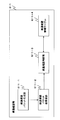
続いて、図2を参照して、一般的なネットワーク疎通確認システムの疎通確認ノード610上で動作する疎通確認部611に含まれる機能ブロックについて説明する。
疎通確認部611は、疎通確認パケット生成部611-1、疎通確認パケット送受信部611-2、疎通確認判断部611-3及び疎通確認情報テーブル611-4を含む。
疎通確認パケット生成部611-1は、疎通確認パケットを生成する機能を有する。
また、疎通確認パケット送受信部611-2は、疎通確認パケット生成部611-1が生成した疎通確認パケットを運用ノード621~運用ノード62Nに対して送信する。そして、疎通確認パケットを受信した運用ノード621~運用ノード62Nは受信した疎通確認パケットに対する応答として疎通確認応答パケットを疎通確認部611に宛てて送信する。疎通確認パケット送受信部611-2は、この疎通確認応答パケットの受信を行う機能を有する。
更に、疎通確認判断部611-3は、疎通確認を行う。疎通確認の具体的な方法については後述する。
更に、疎通確認情報テーブル611-4は、疎通確認を行う際に利用する情報と共に疎通確認の結果を含む情報である疎通確認情報を保持する。
続いて、図3を参照して疎通確認情報テーブル611-4の具体的な内容について説明する。ここで、図3は疎通確認情報テーブル611-4の一具体例を表す図である。
図3を参照すると、疎通確認情報テーブル611-4には、疎通確認の対象であり、疎通確認情報テーブル611-4が管理する対象である運用ノード621~62Nを示す項目である「運用ノード」が項目として設けられている。また、疎通確認情報テーブル611-4には、各運用ノードの疎通確認結果を示す項目である「疎通確認」が項目として設けられている。更に、疎通確認情報テーブル611-4には、疎通確認パケット送受信部611-2が、リモートホスト500が疎通確認パケットを送信してから、疎通確認パケット送受信部611-2が、疎通確認応答パケットを受信するまでの経過時間を示す「遅延」が項目として設けられている。
続いて、疎通確認ノード610のハードウェア構成例を表す図である図4を参照して、疎通確認ノード610のハードウェア構成について説明する。
図4を参照すると、疎通確認ノード610は、CPU610-1と、通信制御部610-2と、メモリ610-3と、第1のネットワークインターフェース部610-4と、第2のネットワークインターフェース部610-5を含む。なお、以下で説明する本発明の実施形態に関する図も含め、図中では「ネットワークインターフェース部」を適宜「NW I/F部」と表記する。
そして、通信を実行するためのデバイスである通信制御部610-2にはCPU610-1及びメモリ610-3が接続される。
そして、上述した疎通確認部611に含まれる各機能ブロックは、CPU610-1が、メモリ610-3又は他のメモリ(図示せず。)等の記憶装置に格納されているプログラムに従って演算処理を行い、演算処理結果に応じて疎通確認ノード610に含まれる各ハードウェアを制御することにより実現される。
また、第1のネットワークインターフェース部610-4は、疎通確認ノード610がリモートホスト500に接続するためのネットワークインターフェース部である。更に、第2のネットワークインターフェース部610-5は、疎通確認ノード610がセグメント600内の運用ノード621~運用ノード62Nに接続するためのネットワークインターフェース部である。
上述したような構成の一般的なネットワーク疎通確認システムは次のように動作する。
まず、リモートホスト500が第1のネットワークインターフェース部610-4を介して各疎通確認ノード610それぞれに接続する。そして、リモートホスト500が遠隔で操作を行うことにより、各疎通確認ノード610の疎通確認部611をそれぞれ動作させる。
各疎通確認部611の疎通確認パケット生成部611-1は、その疎通確認パケット生成部611-1自身を含む疎通確認ノード610が属するセグメント600内の運用ノード621~62Nに対して疎通確認を行うためのパケットである疎通確認パケット(例えば、Pingのecho requestパケット)を生成する。そして、生成した疎通確認パケットを疎通確認パケット送受信部611-2に送信する。
疎通確認パケット送受信部611-2は、疎通確認パケット生成部611-1から受信した疎通確認パケットを、パケットヘッダに記載されたIPアドレスに対応するセグメント600に接続された第2のネットワークインターフェース部610-5へ送信する。また、この際に疎通確認パケットを送信した時刻を測定するための疎通確認パケットタイマを起動させる。
第2のネットワークインターフェース部610-5は、疎通確認パケット送受信部611-2から受信したパケットヘッダに記載されたIPアドレスに対応する運用ノードである運用ノード621~62Nの何れかに疎通確認パケットを送信する。
疎通確認パケットの送信先となった運用ノードである運用ノード621~62Nの何れかは、疎通確認パケットを受信すると、疎通確認ノード610に疎通確認応答パケット(例えば、Pingのecho replyパケット)を送信する。
疎通確認パケット送受信部611-2は、この疎通確認応答パケットを受信すると、疎通確認パケットタイマを停止する。そして、疎通確認パケット送受信部611-2は、疎通確認応答パケットと、疎通確認パケットを送信してから疎通確認応答パケットを受信するまでの経過時間を示す情報とを疎通確認判断部611-3へ送信する。
疎通確認判断部611-3はこの疎通確認応答パケット及び経過時間を示す情報を受信する。また、疎通確認判断部611-3は、疎通確認応答パケットが返信されたことを受け、疎通確認情報テーブル611-4の疎通確認パケットを送信した運用ノードについての情報を更新する。
例として、運用ノード621-1の疎通確認応答パケットを受け取った場合の例を説明する。
この例の場合であれば、疎通確認情報テーブル611-4の運用ノード621-1についての項目「疎通確認」に対して「YES」を書き込み、疎通確認パケットを送信してから疎通確認応答パケットを受信するまでの経過時間を疎通確認情報テーブルの運用ノード621-1についての項目「遅延」に書き込む。今回の例では経過時間が1[ms]であったとして、項目「遅延」に「1」を記載する。
他の例として、運用ノード622-1の疎通確認応答パケットをタイマの時間切れ前に受け取らなかった場合の例を説明する。
疎通確認パケット送信後、一定期間が過ぎるとタイマが時間切れを起こす。この場合に、疎通確認判断部611-3は疎通確認情報テーブル611-4の疎通確認パケットを送信した運用ノードの情報を更新する。
この例の場合であれば、疎通確認情報テーブル611-4の運用ノード622-1の項目「疎通確認」に対して「NO」を書き込む。また、疎通確認応答パケットを受信しておらず、遅延も測定できないことから項目「遅延」には、例えば、無効値を示す数値を記入する。図3では、無効値を示す数値の一例として「N/A」で示している。
以上説明したような一般的技術を利用することにより、各拠点の各セグメント600に含まれる各運用ノード621~62Nの疎通確認を行うことが可能となる。しかしながら、上述したような一般的な技術には、下述するような複数の問題点が存在した。
第1の問題点は、上述した一般的なネットワーク監視システムでは、監視を行う拠点数の増加に伴い、システムが複雑化するということである。
その理由は、拠点数が増加すると、疎通確認ノードを拠点の数設置する必要や、もしくはVPN(Virtual Private Network)接続を拠点の数作成する必要があるということである。
第2の問題点は、上述した一般的なネットワーク監視システムでは、監視を行う拠点数の増加に伴い、システム全体のソフトウェア障害が発生する可能性が増えるということである。
その理由は各拠点に設置されるすべての疎通確認ノード上でOS(Operating System)や疎通確認プログラムが動作する必要があるからである。
そこで、本発明では監視対象の拠点数が増加する場合であっても、システムが複雑となることを防止すると共にシステム上でのソフトウェア障害の発生を防止することが可能な、ネットワーク疎通確認装置、ネットワーク疎通確認方法及びネットワーク疎通確認プログラムを提供することを目的とする。
本発明の第1の観点によれば、コンピュータバスネットワークを介して、1以上のセグメントに接続される疎通確認装置であって、前記1以上のセグメントに含まれる少なくとも1つのセグメントについて、そのセグメントに含まれる1以上の運用ノードと当該疎通確認装置とが疎通できているか否か及び前記運用ノードを含む前記セグメントに備わる下流ブリッジと当該疎通確認装置に備わる上流ブリッジとの間で疎通がとれているか否かを、前記運用ノードを送信先とする疎通確認パケットとそれに対する応答パケットである疎通確認応答パケット並びに当該疎通確認装置に備わる上流ブリッジと、前記運用ノードを含む前記セグメントに備わる下流ブリッジとの間で疎通がとれているか否かをブリッジ間で送受信するためのパケットを用いて確認する疎通確認手段を備えることを特徴とする疎通確認装置が提供される。
本発明の第2の観点によれば、コンピュータバスネットワークを介して、1以上のセグメントに接続される疎通確認装置が行う疎通確認方法であって、前記1以上のセグメントに含まれる少なくとも1つのセグメントについて、そのセグメントに含まれる1以上の運用ノードと当該疎通確認装置とが疎通できているか否か及び前記運用ノードを含む前記セグメントに備わる下流ブリッジと当該疎通確認装置に備わる上流ブリッジとの間で疎通がとれているか否かを、前記運用ノードを送信先とする疎通確認パケットとそれに対する応答パケットである疎通確認応答パケット並びに当該疎通確認装置に備わる上流ブリッジと、前記運用ノードを含む前記セグメントに備わる下流ブリッジとの間で疎通がとれているか否かをブリッジ間で送受信するためのパケットを用いて確認する疎通確認ステップを有することを特徴とする疎通確認方法が提供される。
本発明の第3の観点によれば、コンピュータバスネットワークを介して、1以上のセグメントに接続される疎通確認装置としてコンピュータを機能させるための疎通確認プログラムであって、前記コンピュータを、前記1以上のセグメントに含まれる少なくとも1つのセグメントについて、そのセグメントに含まれる1以上の運用ノードと当該疎通確認装置とが疎通できているか否か及び前記運用ノードを含む前記セグメントに備わる下流ブリッジと当該疎通確認装置に備わる上流ブリッジとの間で疎通がとれているか否かを、前記運用ノードを送信先とする疎通確認パケットとそれに対する応答パケットである疎通確認応答パケット並びに当該疎通確認装置に備わる上流ブリッジと、前記運用ノードを含む前記セグメントに備わる下流ブリッジとの間で疎通がとれているか否かをブリッジ間で送受信するためのパケットを用いて確認する疎通確認手段として機能させることを特徴とする疎通確認プログラムが提供される。
本発明によれば、監視対象の拠点数が増加する場合であっても、システムが複雑となることを防止すると共にシステム上でのソフトウェア障害の発生を防止することが可能となる。
次に、本発明を実施するための形態について図面を参照して詳細に説明する。
本実施形態は、図5に表されるように、概略、コンピュータバスネットワーク1000を介して、1以上のセグメント900に接続される疎通確認装置800であって、前記1以上のセグメント900に含まれる少なくとも1つのセグメント900について、そのセグメント900に含まれる1以上の運用ノード920と当該疎通確認装置800とが疎通できているか否か及び前記運用ノード920を含む前記セグメントに備わる下流ブリッジ910と当該疎通確認装置に備わる上流ブリッジ820との間で疎通がとれているか否かを、前記運用ノード920を送信先とする疎通確認パケットとそれに対する応答パケットである疎通確認応答パケット1001、並びに当該疎通確認装置に備わる上流ブリッジ820と、前記運用ノード920を含む前記セグメント900に備わる下流ブリッジ910との間で疎通がとれているか否かをブリッジ間で送受信するためのパケット1002を用いて確認する疎通確認手段810を備えることを特徴とする疎通確認装置800、というものである。
次に、本発明の実施形態全体である疎通確認システムの構成の一例を表すブロック図である図6を参照する。
図6を参照すると本実施形態は、疎通確認ノード100及び複数(単数であっても良い)のセグメント200を含む。また、疎通確認ノード100及び複数のセグメント200はコンピュータバスネットワーク300を介して接続される。
ここで、コンピュータバスネットワーク300は、例えば、特許文献2に記載されているようなExpEther(エクスプレスイーサ)(登録商標)と呼ばれる技術に対応したものである。ExpEtherとは、或るコンピュータにEthernet(イーサネット)(登録商標)を介して接続されているコンピュータ資源を、そのコンピュータが、PCI Express対応のコンピュータ資源として、用いることができるようにするためのPCI Express over Etherに関連した技術である。より詳細には、ExpEtherとは、例えば、コンピュータのPCI Expressバスに接続されるPCI Expressボード(上流ブリッジとして機能する。)と、拡張機器のPCI Expressバスに接続されるPCI Expressボード(下流ブリッジとして機能する。)とをEthernetで接続し、両ボード間で、Ethernet上の所定のプロトコルの通信をすることにより、拡張機器のPCI Expressバスに接続されているPCI Express機器をコンピュータの資源として利用できるようにした技術である。
疎通確認ノード100は、コンピュータバスネットワーク300を介して、各拠点に設けられた各セグメント200について疎通確認を行う。そして疎通確認ノード100は、疎通確認を実行するための機能ブロックとして疎通確認部110及び上流ブリッジ120を含む。更に、上流ブリッジ120は疎通監視部121を含む。
疎通確認部110は、疎通確認を行うための疎通確認用パケットを生成して、疎通確認用パケットを送受信することにより疎通確認を行う。また、上流ブリッジ120は、コンピュータバスネットワーク300を介した各セグメント200との通信を実現する。更に、疎通監視部121はコンピュータバスネットワーク300を介した通信を監視することによって、疎通確認部110が疎通確認を行うための情報を取得する。
セグメント200は、それぞれが、下流ブリッジ210、ネットワークインターフェース部220及び複数(単数であっても良い)の運用ノード231~23Nを含む。
ここで、セグメント200は、運用ノード231-1~運用ノード23N-Mを相互接続し、それぞれ異なる拠点毎に設置され、拠点毎に離されたサブネットワークである。
また、下流ブリッジ210は、疎通確認ノード100と、コンピュータバスネットワーク300を介して接続される。また、ネットワークインターフェース部220は運用ノード231-1~運用ノード23N-Mが下流ブリッジ210を介してコンピュータバスネットワーク300に接続するためのインターフェースである。
今回の説明においては、ネットワークインターフェース部220はPCI Expressバスに接続されるLANアダプター(NIC:Network Interface Cardとも呼ばれる)であるとする。すなわち、ネットワークインターフェース部220と、ネットワークインターフェース部220に接続される各運用ノード231~23Nはイーサネットにより接続され、LANを構築している。
更に、運用ノード231-1~運用ノード23N-Mは、疎通確認ノード100により疎通確認を行う対象となるノードである。運用ノード231-1~運用ノード23N-Mは、疎通確認部110との間で、上流ブリッジ120、下流ブリッジ210、ネットワークインターフェース部220及びコンピュータバスネットワーク300を介して通信を行う機能を有する機器であればどのような機器であっても良い。
そして、疎通確認ノード100が生成する疎通確認用のパケットは、上流ブリッジ120、コンピュータバスネットワーク300、下流ブリッジ210、ネットワークインターフェース部220を介して運用ノード231-1~運用ノード23N-Mに送信される。そして、疎通確認パケットを受信した運用ノード231-1~運用ノード23N-Mは受信した疎通確認パケットに対する応答として疎通確認応答パケットを生成し、生成した疎通確認応答パケットを疎通確認ノード100に宛てて送信する。疎通確認ノード100は、この疎通確認応答パケットの受信を行う。
続いて、本発明の疎通確認ノード100に含まれるハードウェア及びソフトウェアが協働することにより実現される機能ブロックの一例について詳細に表した機能ブロック図である図7を参照して疎通確認部110に含まれる機能ブロックについて説明をする。
図7を参照すると、疎通確認部110は、疎通確認パケット生成部111、疎通確認パケット送受信部112、疎通確認判断部113、ネットワークインターフェース登録部114及び疎通確認情報テーブル115を含む。また、疎通確認判断部113は、ブリッジ間疎通確認判断部113-1及びセグメント内疎通確認判断部113-2を含む。
疎通確認パケット生成部111は、疎通確認パケットを生成する機能を有する。
また、疎通確認パケット送受信部112は疎通確認パケットを送受信する機能を有する。
更に、疎通確認判断部113は、監視対象の運用ノード231-1~運用ノード23N-Mとの疎通確認の判断を行う機能を有する。より詳細には、ブリッジ間疎通確認判断部113-1は、上流ブリッジ120と下流ブリッジ210の疎通確認の判断をする。これはすなわちブリッジ間での疎通確認を行うということである。一方で、セグメント内疎通確認判断部113-2は、セグメント200-1~セグメント200-Mそれぞれの内部の疎通確認を実行する。つまり、ネットワークインターフェース220-1を介した通信経路における下流ブリッジ210と運用ノード231-1~運用ノード23N-M間の疎通確認を行う。一方で、セグメント内疎通確認判断部113-2は、ネットワークインターフェース220-1を介した通信経路における、下流ブリッジ210と運用ノード231-1~運用ノード23N-M間の疎通確認を行う。これはすなわちセグメント200-1~セグメント200-Mそれぞれの内部の疎通確認を行うということである。
更に、ネットワークインターフェース登録部114は、新たなネットワークインターフェース部220が新たに接続されたか否かの接続監視を行う。そして、ネットワークインターフェース登録部114は、新たなネットワークインターフェース部220が新たに接続された際に、新たに接続されたネットワークインターフェース部220を疎通確認情報テーブル115に登録する。
更に、疎通確認情報テーブル115は、疎通確認判断部113による疎通確認の判断結果の管理を行うためのテーブルである。
続いて、疎通確認部110に含まれる疎通確認情報テーブル115の内容の一例を表す図8を参照して疎通確認情報テーブル115について説明をする。
図8を参照すると、疎通確認情報テーブル115には、疎通確認情報テーブル115が管理するネットワークインターフェース部220を示す項目である「対応ネットワークインターフェース」が項目として設けられている。疎通確認情報テーブル115が管理するネットワークインターフェース部220とは、すなわち、疎通確認ノード100が監視対象とするネットワークインターフェース部220である。
また、疎通確認情報テーブル115には、対応ネットワークインターフェースの項目に記載されたネットワークインターフェース部220に接続される運用ノード231~23Nを示す項目である「運用ノード」が項目として設けられている。
更に、疎通確認情報テーブル115には、対応ネットワークインターフェースの項目に記載されたネットワークインターフェース部220に接続された下流ブリッジ210と上流ブリッジ120間の疎通確認結果を示す項目である「疎通確認ブリッジ間」が項目として設けられている。「疎通確認ブリッジ間」は、疎通確認装置に備わる上流ブリッジと、運用ノードを含むセグメントに備わる下流ブリッジとの間で疎通がとれているか否かを示す。
更に、疎通確認情報テーブル115には、運用ノードの項目に記載された運用ノード231~23Nと、この運用ノード231~23Nと同一のセグメント200内のネットワークインターフェース部220との接続確認結果を示す項目である「疎通確認セグメント内」が項目として設けられている。「疎通確認セグメント内」は、運用ノードを含む前記セグメント内で、運用ノードと下流ブリッジとの間で疎通がとれているか否かを示す。
更に、疎通確認情報テーブル115には、疎通確認部110が疎通確認パケットを送信してから、運用ノードの項目に記載された運用ノード231~23Nから疎通確認応答パケットを受信するまでの遅延時間を示す項目である「遅延」が項目として設けられている。
続いて、疎通確認ノード100を実現するためのハードウェア構成の一例について図9を参照して説明する。図9を参照すると、疎通確認ノード100は、CPU101、ルートコンプレックス102、メモリ103、上流ブリッジ120とを含む。そして、上流ブリッジ120はコンピュータバスネットワーク300と接続される。
ここで、本ハードウェア構成例は、具体的な通信方法の一例として、疎通確認ノード100による通信がPCI-SIG(PCI Special Interest Group)で標準化されている規格であるPCI Express(登録商標)規格に準拠して行われると想定した場合のハードウェア構成例である。
そのため、疎通確認ノード100には、PCI Express規格のツリー構造の最上位に位置するルートコンプレックス102が含まれる。そして、ルートコンプレックス102にはCPU101がシステムバスにより接続され、メモリ103がメモリバスにより接続される。
そして、上述した疎通確認部110に含まれる各機能ブロックは、CPU101が、メモリ103又は他のメモリ(図示せず。)等の記憶装置に格納されている本実施形態特有のプログラムに従って演算処理を行い、演算処理結果に応じて疎通確認ノード100に含まれる各ハードウェアを制御することにより実現される。
また、本実施形態では、上流ブリッジ120と各下流ブリッジ210が協働することにより、各ネットワークインターフェース部220は疎通確認ノード100が有するネットワークインターフェース部として機能する。これを実現するためには、例えば、上述したExpEther(エクスプレスイーサ)の技術を用いる。
このような技術を利用することにより、例えば、第1-1の運用ノード231-1から第N-Mの運用ノード23N-Mとして、PCI Express機器を用いれば、これらが、疎通確認ノードのルートコンプレックス102に接続されたPCI Express機器であるかのように扱うことができる。そのため、1つの疎通確認ノード100のみで、第1-1の運用ノード231-1から第N-Mの運用ノード23N-Mに関する疎通確認を行うことができるようになる。
説明を繰り返すことになるが、通常の技術では、図1に示すように、疎通確認ノード610を全ての拠点に設ける必要があった。通常技術では、各拠点に設けた疎通確認ノードのために複雑なプログラムを別途導入する必要があった。
本実施形態では、例えば疎通確認部110をプログラム及びハードウェアで実現するような場合に、本実施形態特有のプログラムを1つの疎通確認ノード100のみに組み込めば足りる。これにより、ネットワーク監視システムが監視を行う拠点数が増加した場合にも単純なシステム構成を取ることが可能となる。
次に、上流ブリッジ120内の機能ブロックである疎通監視部121の動作について詳細に説明する。
疎通監視部121は、パケットの送受信状況を監視する。監視対象となるパケットは二種類あり、その一つめが、ルートコンプレックス102が生成し且つルートコンプレックス102がコンピュータバスネットワーク300へ送信するパケットである。また、もう1つが、コンピュータバスネットワーク300を介して受信するパケットである。疎通監視部121は、これらのパケットの送受信を監視する。
疎通監視部121が行う監視方法の具体例として例えば2つの方法が考えられる。一つめの方法は、ルートコンプレックス102が生成し、送信するパケットに対して応答パケットが必要なパケットが、ルートコンプレックス102から送信された場合に、応答パケットが返信されてくるまでの時間を計り、タイマ切れを検知するという方法である。そして、もう一つの方法は、上流ブリッジ120及び下流ブリッジ210が定期的に接続監視を行うブリッジ間接続監視パケットを送信するという方法である。
まず、一つ目のルートコンプレックス102が生成し、送信するパケットに対して応答パケットが必要なパケットが、ルートコンプレックス102から送信された場合に、応答パケットが返信されてくるまでの時間を計り、タイマ切れを検知するという方法について説明する。
この方法では、ルートコンプレックス102が生成し、送信するパケットに対して応答パケットが必要なパケットを利用する。ここで応答パケットが必要なパケットとは、例えばPCI Express規格に準拠したメモリリードアクセスやコンフィグレーションアクセスのことを指す。
疎通監視部121は、疎通確認ノード100が何れかの下流ブリッジ210へ応答パケットが必要なパケットを送信した際、パケットのシーケンスナンバの保存を行うと共にタイマを起動する。
そして、疎通監視部121は送信したパケットに対する応答パケットを、疎通確認ノード100がタイマ切れの前に受信すると、タイマを停止し、応答パケットをルートコンプレックス102へ送信する。
一方で、疎通監視部121は一定期間経過し、タイマがタイマ切れを起こすと、タイマ切れを起こしたパケットの送信対象である下流ブリッジ210との接続が切断されたと認識し、疎通監視部121内のレジスタに切断対象の下流ブリッジ210を記載する。
次に、もう一つの方法である上流ブリッジ120及び下流ブリッジ210が定期的に接続監視を行うパケットを送信する方法について説明する。
この方法では、ブリッジ識別情報を用いる。ここで、ブリッジ識別情報とは各ブリッジを識別するための情報であり、例えば所定のIDを割り当てることにより生成する。そして、疎通監視部121及び各疎通監視部211は、定期的に他のブリッジに対して疎通監視部121及び各疎通監視部211自身が含まれているブリッジのブリッジ識別情報を記載したブリッジ間接続監視パケットを送信する。送信は例えばブロードキャストにて行う。
また、上流ブリッジ120内の疎通監視部121は上流ブリッジ120に下流ブリッジ210が接続された際にブリッジ識別情報を取得する。つまり、上流ブリッジ120内の疎通監視部121は上流ブリッジ120に接続されている全ての下流ブリッジ210のブリッジ識別情報を登録している。
そして、上流ブリッジ120内の疎通監視部121は、下流ブリッジ210からブリッジ間接続監視パケットを受信した際、そのパケットに記載されるブリッジ識別情報を参照する。
そして参照の結果、上流ブリッジ120に登録されている下流ブリッジ210のブリッジ識別情報であれば上流ブリッジ120とその下流ブリッジ間210の接続が確立されていると認識する。
一方で、上流ブリッジ120に登録されている或る下流ブリッジ210から定期的に送信されてくるはずのブリッジ識別情報が送信されてこない場合には上流ブリッジ120とこの或る下流ブリッジ210間の接続が切断されていると認識し、レジスタにその情報を記載する。
以上説明したような各動作を行うことにより、何れの下流ブリッジ210との接続が切断されているのかを把握することが可能となる。そして、或る下流ブリッジ210との接続が切断している旨の情報をレジスタに記載することが可能となる。
また、疎通確認部110からレジスタに記載された情報がリードされた際に、レジスタをクリアしてリードされた情報を削除する。これにより、疎通確認部110が或る下流ブリッジ210との接続が切断している旨を把握することが可能となる。
次に、疎通確認部110に含まれる各機能ブロックの動作について詳細に説明する。
ネットワークインターフェース登録部114は疎通確認部110が監視する対象の各ネットワークインターフェース部220の登録及びネットワークインターフェース部220が監視する各運用ノード231~23Nの登録を行う。
また、ネットワークインターフェース登録部114は、疎通確認部110が動作中に監視する対象の新たなネットワークインターフェース部220が新たに接続された場合、その新たなネットワークインターフェース220を疎通確認ノード100と接続される新たな接続対象とする。また、ネットワークインターフェース登録部114は、この新たに接続されたネットワークインターフェース部220が接続されるセグメント200に含まれる運用ノード231~23Nを新たな監視対象として登録する。
運用ノード231~23Nの登録は、新たに接続があった際にネットワーク疎通確認者が入力するという方法をとっても良いし、予め疎通確認ソフトウェアに追加される運用ノード231~23Nを登録しておくという方法をとっても良い。
疎通確認パケット生成部111は、ネットワークインターフェース登録部114により登録されている運用ノード231~23Nに対する疎通確認パケットを生成する。
ここで、疎通確認パケット及び疎通確認応答パケットについて表す図である図10を参照して疎通確認パケット及び疎通確認応答パケットについて説明する。
図10を参照すると、疎通確認パケット及び疎通確認応答パケットは3つのヘッダを含む。そして、本体部はPingパケットとなっている。
まず、疎通確認パケットを参照すると、イーサネットヘッダには、送信先MACアドレスとして下流ブリッジ210のMACアドレスが、送信元MACアドレスとして上流ブリッジ120のMACアドレスが含まれる。また、TLP(Transaction Layer Packet)ヘッダには、送信先アドレスとして下流ブリッジ210のアドレスが、送信元アドレスとして上流ブリッジ120のアドレスが含まれる。なお、TLPヘッダにおいて用いるアドレス情報は、例えばPCI Expressに準拠したアドレス情報を用いることができる。更に、セグメント内ヘッダには、送信先IPアドレスとして運用ノード231-1~23N-MのIPアドレスが、送信元IPアドレスとしてネットワークインターフェース部220のIPアドレスが含まれる。
一方、疎通確認応答パケットを参照すると、イーサネットヘッダには、送信元MACアドレスとして下流ブリッジ210のMACアドレスが、送信先MACアドレスとして上流ブリッジ120のMACアドレスが含まれる。また、TLPヘッダには、送信元アドレスとして下流ブリッジ210のアドレスが、宛先アドレスとして上流ブリッジ120のアドレスが含まれる。更に、セグメント内ヘッダには、送信元IPアドレスとして運用ノード231-1~23N-MのIPアドレスが、送信先IPアドレスとしてネットワークインターフェース部220のIPアドレスが含まれる。
疎通確認パケット生成部111が生成するパケットは、例えば、イーサネットヘッダには、送信先MACアドレスとして今回の監視対象の運用ノードが属するセグメントの下流ブリッジ210のMACアドレスが、送信元MACアドレスとして上流ブリッジ120のMACアドレスが、TLPヘッダには、宛先アドレスとして今回の監視対象の運用ノードが属するセグメントの下流ブリッジ210のアドレスが、送信元アドレスとして上流ブリッジ120のアドレスが、セグメント内ヘッダには、送信先IPアドレスとして今回の監視対象の運用ノードのIPアドレスが、送信元IPアドレスとして今回の監視対象の運用ノードが属するセグメントのネットワークインターフェース部220のIPアドレスが、記載されたPingパケットを生成する。
そして、疎通確認パケット生成部111は生成した疎通確認パケットを疎通確認パケット送受信部112へ送信する。
疎通確認パケット送受信部112は、疎通確認パケット生成部111から疎通確認パケットを受信すると、タイマを起動すると共に受信した疎通確認パケットをコンピュータバスネットワーク300に送信する。
また、疎通確認パケット送受信部112は、送信した疎通確認パケットに対する疎通確認応答パケットを受信した場合、タイマを停止し、疎通確認応答パケットの情報の内、少なくともセグメント内ヘッダに記載されている送信先及び送信元のIPアドレスと、タイマ切れが起きなかった旨とを、疎通確認判断部113へ通知する。
一方で、疎通確認パケット送受信部112は、疎通確認応答パケットを受信することなくタイマが一定時間経過し、タイマ切れを起こした際、送信した疎通確認パケットに記載された、セグメント内ヘッダに記載されている送信先及び送信元のIPアドレスと、TLPヘッダ又はイーサネットヘッダに記載されている下流ブリッジ210を特定するアドレスと、タイマ切れが起きた旨とを疎通確認判断部113へ通知する。
疎通確認判断部113は疎通確認パケット送受信部112からの通知情報に基づいて疎通確認情報テーブル115を更新する。
ここで、疎通確認判断部113は、上流ブリッジ120と下流ブリッジ210間の疎通判断を行うブリッジ間疎通確認判断部113-1と、ネットワークインターフェースと運用ノード間の疎通判断を行うセグメント内疎通確認判断部113-2を含む。
そして、ブリッジ間疎通確認判断部113-1は疎通確認パケット送受信部112から疎通確認パケットに対する疎通確認応答パケットを受信した場合、その疎通確認応答パケットのセグメント内ヘッダの送信先IPアドレスに記載されたネットワークインターフェース部220に接続された下流ブリッジ210との接続ができていると判断し、その情報を疎通確認情報テーブル115に送信する。すなわち、疎通確認情報テーブル115の今回の判断対象とした下流ブリッジ210についての項目「疎通確認ブリッジ間」に「Yes」を記載する。
一方、ブリッジ間疎通確認判断部113-1は疎通確認パケット送受信部112から疎通確認パケットのタイマ切れの通知を受けた場合、その疎通確認パケットのセグメント内ヘッダの送信元に記載されたネットワークインターフェース部220に接続された下流ブリッジ210との接続ができているかを確認するため、疎通監視部121内のレジスタに記載された情報を参照し、疎通確認パケットの送信元に記載されたネットワークインターフェース部220のブリッジ間接続状態を取得する。
そして、ブリッジ間疎通確認判断部113-1は、ブリッジ間接続状態が接続切れを示す場合、疎通確認情報テーブル115の今回の判断対象とした下流ブリッジ210についての項目「疎通確認ブリッジ間」に「No」を記載する。
一方、ブリッジ間疎通確認判断部113-1はブリッジ間接続状態が接続を示す場合、疎通確認情報テーブル115の今回の判断対象とした下流ブリッジ210についての項目「疎通確認ブリッジ間」に「Yes」を記載する。
また、セグメント内疎通確認判断部113-2は、疎通確認パケット送受信部112から疎通確認パケットに対する疎通確認応答パケットを受信した場合、その疎通確認応答パケットのセグメントヘッダ内の送信元IPアドレスに記載された運用ノード231~23Nが疎通可能であると判断し、疎通確認テーブル115を更新する。すなわち、疎通確認情報テーブル115の今回の判断対象とした運用ノード231~23Nについての項目「疎通確認セグメント内」に「Yes」を記載する。
一方、セグメント内疎通確認判断部113-2は、疎通確認パケット送受信部112から疎通確認パケットのタイマ切れが通知された場合、その疎通確認パケットの送信先に記載された運用ノード231~23Nが疎通不可であったと判断し、疎通確認情報テーブル115を更新する。すなわち、疎通確認情報テーブル115の今回の判断対象とした運用ノード231~23Nについての項目「疎通確認セグメント内」に「No」を記載する。
疎通確認情報テーブル115は、疎通確認プログラムが監視する上流ブリッジ120と下流ブリッジ210の全対とネットワークインターフェース220と運用ノード231~23Nの全対の導通状態と疎通確認パケット送信から受信までの遅延を保有する。この情報は前記疎通確認判断部113により更新される。
次に、図6~図11を参照して本実施形態の疎通確認方法の動作について詳細に説明する。
図11のフローチャートを参照すると、まず、疎通確認パケット生成部111がネットワークインターフェース登録部114に登録されている疎通確認パケット送信対象の運用ノードに対して送信する疎通確認パケットを生成する。そして、疎通確認パケット送受信部112は生成されたパケットを指定されたネットワークインターフェース部220に宛てて送信する。ルートコンプレックス102は上記のネットワークインターフェース部220へ疎通確認パケットを送信する命令を受け、ネットワークインターフェース部220に対してパケットを生成し、送信する(ステップS1)。
また、パケット送受信部は、疎通確認パケット送信後に疎通確認パケットの送信元IPアドレスおよび送信先IPアドレスに対応するタイマを起動する(ステップS2)。このタイマのタイマ切れ値は所定の値であるが、この所定の値についてはネットワーク疎通確認管理者が決定できる値であるとする。
次に、送信した疎通確認パケットに対する応答である疎通確認応答パケットを、タイム切れする前に、受信したか否かを監視する(ステップS3)。
ここで、タイム切れする前に、セグメント内疎通確認判断部113-2が、疎通確認パケット送受信部112から疎通確認パケットに対する疎通確認応答パケットを受信した場合(ステップS3においてYes)、ステップS4に遷移する。
ステップS4において、セグメント内疎通確認判断部113-2は、ステップS3にて受信した疎通確認応答パケットのセグメント内ヘッダの送信元IPアドレスに記載された運用ノードが疎通可能であると判断し、疎通確認テーブル115を更新する。
つまり、ブリッジ間疎通確認判断部113-1は、疎通確認装置に備わる上流ブリッジと、運用ノードを含むセグメントに備わる下流ブリッジとの間で疎通がとれているので、「疎通確認ブリッジ間」を「YES」とし、また、セグメント内疎通確認判断部113-2は、運用ノードを含む前記セグメント内で、運用ノードと下流ブリッジとの間で疎通がとれているので、「疎通確認セグメント内」も「YES」とする。
例えば、運用ノード231-1へ送信した疎通確認パケットについての疎通確認応答パケットの返信があった場合、疎通確認情報テーブル115のネットワークインターフェース部220-1についての項目「疎通確認ブリッジ間」に「Yes」を記載する。更に、運用ノード231-1についての項目「疎通確認セグメント内」に「Yes」を記載し、加えて運用ノード231-1についての項目「遅延」に疎通確認パケット送信時間と、疎通確認応答パケット受信時間との差分を記載する。
一方、ステップS3においてタイマ切れが生じた場合(ステップS3においてNo)、ステップS5に遷移する。
ステップS5では、ブリッジ間疎通確認判断部113-1によりブリッジ間の疎通が取れているかを確認するために疎通監視部121のレジスタを参照する。上述したように疎通監視部121のレジスタには、各ブリッジ間と疎通確認が取れているのかが記録されているためである。そして、参照の結果、疎通確認が取れている場合(ステップS5においてYes)、ステップS6に遷移する。
ステップS6では、ブリッジ間の疎通は確認できているが、ネットワークインターフェース部220から運用ノード231~23Nに対して疎通確認が取れない場合と判断し、疎通確認テーブル115を更新する。
つまり、ブリッジ間疎通確認判断部113-1は、疎通確認装置に備わる上流ブリッジと、運用ノードを含むセグメントに備わる下流ブリッジとの間で疎通がとれているので、「疎通確認ブリッジ間」を「YES」とし、また、セグメント内疎通確認判断部113-2は、運用ノードを含む前記セグメント内で、運用ノードと下流ブリッジとの間で疎通がとれていないので、「疎通確認セグメント内」を「NO」とする。
例えば運用ノード232-1に対する疎通確認パケットに対しての判断においてステップS6に遷移した場合、疎通確認判断部113は、疎通確認情報テーブル115のネットワークインターフェース部220-1についての項目「疎通確認ブリッジ間」に「Yes」を記載し、運用ノード232-1についての項目「疎通確認セグメント内」に「No」を記載する。
また、ステップS5においてブリッジ間の疎通が取れていないと判断した場合ステップS7に遷移する。ステップS7では、単にネットワークインターフェース部220から運用ノード231~23Nに対して疎通確認が取れないのみならず、ブリッジ間の疎通が取れていない場合となる。
つまり、ブリッジ間疎通確認判断部113-1は、疎通確認装置に備わる上流ブリッジと、運用ノードを含むセグメントに備わる下流ブリッジとの間で疎通がとれていないので、「疎通確認ブリッジ間」をNOとする。なお、運用ノードを含む前記セグメント内で、運用ノードと下流ブリッジとの間で疎通がとれているか否かの判断をすることができないが、セグメント内疎通確認判断部113-2は、「疎通確認セグメント内」もNOとする。
例えば、ネットワークインターフェース部220-Mに対するブリッジ間の疎通確認が取れない場合、ネットワークインターフェース部220-Mについての項目「疎通確認ブリッジ間」に「No」を記載する。そして更に、そのネットワークインターフェース部220-Mに接続する運用ノードである、運用ノード231-M~運用ノード23N-Mについての項目「疎通確認セグメント内」の全てに「No」と記載する。
本実施形態は以上の動作により、それぞれの状況に応じて疎通確認テーブル115を更新し、疎通確認を実行することが可能となる。
次に図6、図7、図9及び図12を参照して本実施形態の疎通確認部110の動作中に新たな監視対象の拠点、すなわち新たなセグメント200が追加された際の動作について詳細に説明する。
まず、ネットワークインターフェース登録部114が、新たなネットワークインターフェース部220が追加されたかどうかを確認する(ステップS11)。
この確認方法は、例えばネットワークインターフェース部220がPCI Expressにより接続されるデバイスであれば、PCI Expressにより規定されているHotPlugの機能を利用することにより新たなネットワークインターフェース部220の追加を検知し、その情報をネットワークインターフェース登録部114が取得するという方法である。
そして、このステップ11において新たなネットワークインターフェース部220の追加が確認されなかった場合(ステップS11においてNo)、今回の処理は終了とし、上述の所定の時間周期となった際に再度ステップS11から処理を開始する。
一方で、このステップ11において新たなネットワークインターフェース部220の追加が確認された場合(ステップS11においてNo)、ステップS12に遷移する。
ステップS12では、新たなネットワークインターフェース部220が疎通確認するセグメント200の運用ノード231~23Nを登録する。この登録方法はネットワーク疎通確認者が入力するという方法をとっても良いし、予め疎通確認ソフトウェアに追加される運用ノード231~23Nを登録しておくという方法をとっても良い。登録完了後、ステップS13に遷移する。
ステップS13では疎通確認パケットの送信対象に新たなネットワークインターフェース部220を登録し、更に、そのネットワークインターフェース部200から送信する送信先運用ノード231~23Nの登録を行う。
その後ステップS14では疎通確認情報テーブル115に追加された新たなネットワークインターフェース部220を登録し、更に疎通確認情報テーブル115に、そのネットワークインターフェース部220から送信する送信先運用ノード231~23Nの登録を行う。
続いて、本実施形態が奏する効果について詳細に説明する。
第1の効果は、ネットワーク監視システムが監視を行う拠点数が増加した場合にも単純なシステム構成が取れ、更にネットワーク疎通確認を行うシステムの構築にかかる時間を削減できることにある。
その理由は、疎通確認ノードと各拠点に分散配置されたネットワークインターフェース部は単一のコンピュータとして動作するためである。
また、第2の効果は、一般的なネットワーク監視システムに比べ、動作するプログラムを減らすことができることにある。
その理由は拠点数が増加した場合にも疎通確認ノードは1台であること、疎通確認プログラム以外のプログラムを追加したり動作させたりすることがないということにある。
すなわち、第1及び第2の効果をまとめると、本実施形態では、単一の疎通監視ノードから複数の拠点に対して、一般的なプログラムに大きな改変を加えることなく疎通確認を行うことができるため、システム構成の簡単化及びプログラムの信頼性が向上する。
更に、第3の効果は疎通確認を行うポイントが明確になることにある。
その理由は疎通確認パケットで確認できた情報が上流ブリッジと下流ブリッジ間の障害かネットワークインターフェース部と運用ノード間の障害かの切り分けを行うことができることにある。
更に、第4の効果は、疎通確認ノード動作中に監視拠点が追加された場合にもプログラムを動作させたまま監視対象を増やすことができることにある。
その理由は、ネットワークインターフェース登録部が、新たなネットワークインターフェース部が追加されたかどうかを確認するからである。例えば、ネットワークインターフェース部がPCI Expressにより接続されるデバイスであれば、PCI Expressにより規定されているHotPlugの機能を利用することにより新たなネットワークインターフェース部の追加を検知し、その情報をネットワークインターフェース登録部が登録するからである。
なお、上記の疎通確認ノードは、ハードウェア、ソフトウェア又はこれらの組み合わせにより実現することができる。また、上記の疎通確認ノードにより行なわれる疎通確認方法も、ハードウェア、ソフトウェア又はこれらの組み合わせにより実現することができる。ここで、ソフトウェアによって実現されるとは、コンピュータがプログラムを読み込んで実行することにより実現されることを意味する。
プログラムは、様々なタイプの非一時的なコンピュータ可読媒体(non-transitory computer readable medium)を用いて格納され、コンピュータに供給することができる。非一時的なコンピュータ可読媒体は、様々なタイプの実体のある記録媒体(tangible storage medium)を含む。非一時的なコンピュータ可読媒体の例は、磁気記録媒体(例えば、フレキシブルディスク、磁気テープ、ハードディスクドライブ)、光磁気記録媒体(例えば、光磁気ディスク)、CD-ROM(Read Only Memory)、CD-R、CD-R/W、半導体メモリ(例えば、マスクROM、PROM(Programmable ROM)、EPROM(Erasable PROM)、フラッシュROM、RAM(random access memory))を含む。また、プログラムは、様々なタイプの一時的なコンピュータ可読媒体(transitory computer readable medium)によってコンピュータに供給されてもよい。一時的なコンピュータ可読媒体の例は、電気信号、光信号、及び電磁波を含む。一時的なコンピュータ可読媒体は、電線及び光ファイバ等の有線通信路、又は無線通信路を介して、プログラムをコンピュータに供給できる。
上記の実施形態の一部又は全部は、以下の付記のようにも記載されうるが、以下には限られない。
(付記1) コンピュータバスネットワークを介して、1以上のセグメントに接続される疎通確認装置であって、
前記1以上のセグメントに含まれる少なくとも1つのセグメントについて、そのセグメントに含まれる1以上の運用ノードと当該疎通確認装置とが疎通できているか否か及び前記運用ノードを含む前記セグメントに備わる下流ブリッジと当該疎通確認装置に備わる上流ブリッジとの間で疎通がとれているか否かを、前記運用ノードを送信先とする疎通確認パケットとそれに対する応答パケットである疎通確認応答パケット並びに当該疎通確認装置に備わる上流ブリッジと、前記運用ノードを含む前記セグメントに備わる下流ブリッジとの間で疎通がとれているか否かをブリッジ間で送受信するためのパケットを用いて確認する疎通確認手段を備えることを特徴とする疎通確認装置。
前記1以上のセグメントに含まれる少なくとも1つのセグメントについて、そのセグメントに含まれる1以上の運用ノードと当該疎通確認装置とが疎通できているか否か及び前記運用ノードを含む前記セグメントに備わる下流ブリッジと当該疎通確認装置に備わる上流ブリッジとの間で疎通がとれているか否かを、前記運用ノードを送信先とする疎通確認パケットとそれに対する応答パケットである疎通確認応答パケット並びに当該疎通確認装置に備わる上流ブリッジと、前記運用ノードを含む前記セグメントに備わる下流ブリッジとの間で疎通がとれているか否かをブリッジ間で送受信するためのパケットを用いて確認する疎通確認手段を備えることを特徴とする疎通確認装置。
(付記2) 付記1に記載の疎通確認装置であって、
前記疎通確認手段は、
当該疎通確認装置に備わる上流ブリッジと、前記運用ノードを含む前記セグメントに備わる下流ブリッジとの間で疎通がとれているか否かをこれらのブリッジ間で送受信するためのパケットを用いて判断するブリッジ間疎通確認判断手段と、
前記運用ノードを含む前記セグメント内で、前記運用ノードと前記下流ブリッジとの間で疎通がとれているか否かを前記疎通確認パケット及び前記疎通確認応答パケットを用いて判断するセグメント内疎通確認判断手段と、
を備えることを特徴とする疎通確認装置。
前記疎通確認手段は、
当該疎通確認装置に備わる上流ブリッジと、前記運用ノードを含む前記セグメントに備わる下流ブリッジとの間で疎通がとれているか否かをこれらのブリッジ間で送受信するためのパケットを用いて判断するブリッジ間疎通確認判断手段と、
前記運用ノードを含む前記セグメント内で、前記運用ノードと前記下流ブリッジとの間で疎通がとれているか否かを前記疎通確認パケット及び前記疎通確認応答パケットを用いて判断するセグメント内疎通確認判断手段と、
を備えることを特徴とする疎通確認装置。
(付記3) 付記2に記載の疎通確認装置であって、
前記ブリッジ間疎通確認判断手段は、
疎通の確認の対象となる前記運用ノードについて、
当該疎通確認装置と、前記運用ノードとの間で疎通がとれている場合、及び、当該疎通確認装置と、前記運用ノードとの間で疎通がとれていないが、当該疎通確認装置に備わる上流ブリッジと、前記運用ノードを含む前記セグメントに備わる下流ブリッジとの間で疎通がとれている場合に、当該疎通確認装置に備わる上流ブリッジと、前記運用ノードを含む前記セグメントに備わる下流ブリッジとの間で疎通がとれているという判断結果を出し、
前記ブリッジ間疎通確認判断手段は、
疎通の確認の対象となる前記運用ノードについて、
当該疎通確認装置に備わる上流ブリッジと、前記運用ノードを含む前記セグメントに備わる下流ブリッジとの間で疎通がとれていない場合に、当該疎通確認装置に備わる上流ブリッジと、前記運用ノードを含む前記セグメントに備わる下流ブリッジとの間で疎通がとれていないという判断結果を出すことを特徴とする疎通確認装置。
前記ブリッジ間疎通確認判断手段は、
疎通の確認の対象となる前記運用ノードについて、
当該疎通確認装置と、前記運用ノードとの間で疎通がとれている場合、及び、当該疎通確認装置と、前記運用ノードとの間で疎通がとれていないが、当該疎通確認装置に備わる上流ブリッジと、前記運用ノードを含む前記セグメントに備わる下流ブリッジとの間で疎通がとれている場合に、当該疎通確認装置に備わる上流ブリッジと、前記運用ノードを含む前記セグメントに備わる下流ブリッジとの間で疎通がとれているという判断結果を出し、
前記ブリッジ間疎通確認判断手段は、
疎通の確認の対象となる前記運用ノードについて、
当該疎通確認装置に備わる上流ブリッジと、前記運用ノードを含む前記セグメントに備わる下流ブリッジとの間で疎通がとれていない場合に、当該疎通確認装置に備わる上流ブリッジと、前記運用ノードを含む前記セグメントに備わる下流ブリッジとの間で疎通がとれていないという判断結果を出すことを特徴とする疎通確認装置。
(付記4) 付記2又は3に記載の疎通確認装置であって、
前記セグメント内疎通確認判断手段は、
疎通の確認の対象となる前記運用ノードについて、
当該疎通確認装置と、前記運用ノードとの間で疎通がとれている場合に、当該疎通確認装置と、前記運用ノードとの間で疎通がとれているという判断結果を出し、
前記ブリッジ間疎通確認判断手段は、
疎通の確認の対象となる前記運用ノードについて、
当該疎通確認装置に備わる上流ブリッジと、前記運用ノードを含む前記セグメントに備わる下流ブリッジとの間で疎通がとれているが、当該疎通確認装置と、前記運用ノードとの間で疎通がとれていない場合と、当該疎通確認装置に備わる上流ブリッジと、前記運用ノードを含む前記セグメントに備わる下流ブリッジとの間で疎通がとれていない場合に、当該疎通確認装置と、前記運用ノードとの間で疎通がとれていないという判断結果を出すことを特徴とする疎通確認装置。
前記セグメント内疎通確認判断手段は、
疎通の確認の対象となる前記運用ノードについて、
当該疎通確認装置と、前記運用ノードとの間で疎通がとれている場合に、当該疎通確認装置と、前記運用ノードとの間で疎通がとれているという判断結果を出し、
前記ブリッジ間疎通確認判断手段は、
疎通の確認の対象となる前記運用ノードについて、
当該疎通確認装置に備わる上流ブリッジと、前記運用ノードを含む前記セグメントに備わる下流ブリッジとの間で疎通がとれているが、当該疎通確認装置と、前記運用ノードとの間で疎通がとれていない場合と、当該疎通確認装置に備わる上流ブリッジと、前記運用ノードを含む前記セグメントに備わる下流ブリッジとの間で疎通がとれていない場合に、当該疎通確認装置と、前記運用ノードとの間で疎通がとれていないという判断結果を出すことを特徴とする疎通確認装置。
(付記5) 付記1乃至4の何れか1に記載の疎通確認装置であって、
前記疎通確認判断手段は、当該疎通確認装置と疎通できている前記運用ノードについては、前記疎通確認パケットを送信した時刻から、前記疎通確認応答パケットを受信した時刻までの遅延時間を測定することを特徴とする疎通確認装置。
前記疎通確認判断手段は、当該疎通確認装置と疎通できている前記運用ノードについては、前記疎通確認パケットを送信した時刻から、前記疎通確認応答パケットを受信した時刻までの遅延時間を測定することを特徴とする疎通確認装置。
(付記6) 付記1乃至5の何れか1に記載の疎通確認装置であって、
当該疎通確認装置は、エクスプレスイーサ(登録商標)に準拠した装置であることを特徴とする疎通確認装置。
当該疎通確認装置は、エクスプレスイーサ(登録商標)に準拠した装置であることを特徴とする疎通確認装置。
(付記7) 付記1乃至6の何れか1に記載の疎通確認装置であって、
前記疎通確認手段動作中であっても新たな下流ブリッジの新たな接続を検知すると共に、前記疎通確認手段の動作を継続することを特徴とする疎通確認装置。
前記疎通確認手段動作中であっても新たな下流ブリッジの新たな接続を検知すると共に、前記疎通確認手段の動作を継続することを特徴とする疎通確認装置。
(付記8) 付記7に記載の疎通確認装置であって、
前記新たな下流ブリッジが含まれるセグメントを新たに疎通確認の対象とすることを特徴とする疎通確認装置。
前記新たな下流ブリッジが含まれるセグメントを新たに疎通確認の対象とすることを特徴とする疎通確認装置。
(付記9) コンピュータバスネットワークを介して、1以上のセグメントに接続される疎通確認装置が行う疎通確認方法であって、
前記1以上のセグメントに含まれる少なくとも1つのセグメントについて、そのセグメントに含まれる1以上の運用ノードと当該疎通確認装置とが疎通できているか否か及び前記運用ノードを含む前記セグメントに備わる下流ブリッジと当該疎通確認装置に備わる上流ブリッジとの間で疎通がとれているか否かを、前記運用ノードを送信先とする疎通確認パケットとそれに対する応答パケットである疎通確認応答パケット並びに当該疎通確認装置に備わる上流ブリッジと、前記運用ノードを含む前記セグメントに備わる下流ブリッジとの間で疎通がとれているか否かをブリッジ間で送受信するためのパケットを用いて確認する疎通確認ステップを有することを特徴とする疎通確認方法。
前記1以上のセグメントに含まれる少なくとも1つのセグメントについて、そのセグメントに含まれる1以上の運用ノードと当該疎通確認装置とが疎通できているか否か及び前記運用ノードを含む前記セグメントに備わる下流ブリッジと当該疎通確認装置に備わる上流ブリッジとの間で疎通がとれているか否かを、前記運用ノードを送信先とする疎通確認パケットとそれに対する応答パケットである疎通確認応答パケット並びに当該疎通確認装置に備わる上流ブリッジと、前記運用ノードを含む前記セグメントに備わる下流ブリッジとの間で疎通がとれているか否かをブリッジ間で送受信するためのパケットを用いて確認する疎通確認ステップを有することを特徴とする疎通確認方法。
(付記10) 付記9に記載の疎通確認方法であって、
前記疎通確認ステップは、
当該疎通確認装置に備わる上流ブリッジと、前記運用ノードを含む前記セグメントに備わる下流ブリッジとの間で疎通がとれているか否かをこれらのブリッジ間で送受信するためのパケットを用いて判断するブリッジ間疎通確認判断ステップと、
前記運用ノードを含む前記セグメント内で、前記運用ノードと前記下流ブリッジとの間で疎通がとれているか否かを前記疎通確認パケット及び前記疎通確認応答パケットを用いて判断するセグメント内疎通確認判断ステップと、
を有することを特徴とする疎通確認方法。
前記疎通確認ステップは、
当該疎通確認装置に備わる上流ブリッジと、前記運用ノードを含む前記セグメントに備わる下流ブリッジとの間で疎通がとれているか否かをこれらのブリッジ間で送受信するためのパケットを用いて判断するブリッジ間疎通確認判断ステップと、
前記運用ノードを含む前記セグメント内で、前記運用ノードと前記下流ブリッジとの間で疎通がとれているか否かを前記疎通確認パケット及び前記疎通確認応答パケットを用いて判断するセグメント内疎通確認判断ステップと、
を有することを特徴とする疎通確認方法。
(付記11) 付記10に記載の疎通確認方法であって、
前記ブリッジ間疎通確認判断ステップは、
疎通の確認の対象となる前記運用ノードについて、
当該疎通確認装置と、前記運用ノードとの間で疎通がとれている場合、及び、当該疎通確認装置と、前記運用ノードとの間で疎通がとれていないが、当該疎通確認装置に備わる上流ブリッジと、前記運用ノードを含む前記セグメントに備わる下流ブリッジとの間で疎通がとれている場合に、当該疎通確認装置に備わる上流ブリッジと、前記運用ノードを含む前記セグメントに備わる下流ブリッジとの間で疎通がとれているという判断結果を出し、
前記ブリッジ間疎通確認判断ステップは、
疎通の確認の対象となる前記運用ノードについて、
当該疎通確認装置に備わる上流ブリッジと、前記運用ノードを含む前記セグメントに備わる下流ブリッジとの間で疎通がとれていない場合に、当該疎通確認装置に備わる上流ブリッジと、前記運用ノードを含む前記セグメントに備わる下流ブリッジとの間で疎通がとれていないという判断結果を出すことを特徴とする疎通確認方法。
前記ブリッジ間疎通確認判断ステップは、
疎通の確認の対象となる前記運用ノードについて、
当該疎通確認装置と、前記運用ノードとの間で疎通がとれている場合、及び、当該疎通確認装置と、前記運用ノードとの間で疎通がとれていないが、当該疎通確認装置に備わる上流ブリッジと、前記運用ノードを含む前記セグメントに備わる下流ブリッジとの間で疎通がとれている場合に、当該疎通確認装置に備わる上流ブリッジと、前記運用ノードを含む前記セグメントに備わる下流ブリッジとの間で疎通がとれているという判断結果を出し、
前記ブリッジ間疎通確認判断ステップは、
疎通の確認の対象となる前記運用ノードについて、
当該疎通確認装置に備わる上流ブリッジと、前記運用ノードを含む前記セグメントに備わる下流ブリッジとの間で疎通がとれていない場合に、当該疎通確認装置に備わる上流ブリッジと、前記運用ノードを含む前記セグメントに備わる下流ブリッジとの間で疎通がとれていないという判断結果を出すことを特徴とする疎通確認方法。
(付記12) 付記10又は11に記載の疎通確認方法であって、
前記セグメント内疎通確認判断ステップは、
疎通の確認の対象となる前記運用ノードについて、
当該疎通確認装置と、前記運用ノードとの間で疎通がとれている場合に、当該疎通確認装置と、前記運用ノードとの間で疎通がとれているという判断結果を出し、
前記ブリッジ間疎通確認判断ステップは、
疎通の確認の対象となる前記運用ノードについて、
当該疎通確認装置に備わる上流ブリッジと、前記運用ノードを含む前記セグメントに備わる下流ブリッジとの間で疎通がとれているが、当該疎通確認装置と、前記運用ノードとの間で疎通がとれていない場合と、当該疎通確認装置に備わる上流ブリッジと、前記運用ノードを含む前記セグメントに備わる下流ブリッジとの間で疎通がとれていない場合に、当該疎通確認装置と、前記運用ノードとの間で疎通がとれていないという判断結果を出すことを特徴とする疎通確認方法。
前記セグメント内疎通確認判断ステップは、
疎通の確認の対象となる前記運用ノードについて、
当該疎通確認装置と、前記運用ノードとの間で疎通がとれている場合に、当該疎通確認装置と、前記運用ノードとの間で疎通がとれているという判断結果を出し、
前記ブリッジ間疎通確認判断ステップは、
疎通の確認の対象となる前記運用ノードについて、
当該疎通確認装置に備わる上流ブリッジと、前記運用ノードを含む前記セグメントに備わる下流ブリッジとの間で疎通がとれているが、当該疎通確認装置と、前記運用ノードとの間で疎通がとれていない場合と、当該疎通確認装置に備わる上流ブリッジと、前記運用ノードを含む前記セグメントに備わる下流ブリッジとの間で疎通がとれていない場合に、当該疎通確認装置と、前記運用ノードとの間で疎通がとれていないという判断結果を出すことを特徴とする疎通確認方法。
(付記13) 付記9乃至12の何れか1に記載の疎通確認方法であって、
前記疎通確認判断ステップは、当該疎通確認装置と疎通できている前記運用ノードについては、前記疎通確認パケットを送信した時刻から、前記疎通確認応答パケットを受信した時刻までの遅延時間を測定することを特徴とする疎通確認方法。
前記疎通確認判断ステップは、当該疎通確認装置と疎通できている前記運用ノードについては、前記疎通確認パケットを送信した時刻から、前記疎通確認応答パケットを受信した時刻までの遅延時間を測定することを特徴とする疎通確認方法。
(付記14) 付記9乃至13の何れか1に記載の疎通確認方法であって、
当該疎通確認装置は、エクスプレスイーサ(登録商標)に準拠した装置であることを特徴とする疎通確認方法。
当該疎通確認装置は、エクスプレスイーサ(登録商標)に準拠した装置であることを特徴とする疎通確認方法。
(付記15) 付記9乃至14の何れか1に記載の疎通確認方法であって、
前記疎通確認ステップ動作中であっても新たな下流ブリッジの新たな接続を検知すると共に、前記疎通確認ステップの動作を継続することを特徴とする疎通確認方法。
前記疎通確認ステップ動作中であっても新たな下流ブリッジの新たな接続を検知すると共に、前記疎通確認ステップの動作を継続することを特徴とする疎通確認方法。
(付記16) 付記15に記載の疎通確認方法であって、
前記新たな下流ブリッジが含まれるセグメントを新たに疎通確認の対象とすることを特徴とする疎通確認方法。
前記新たな下流ブリッジが含まれるセグメントを新たに疎通確認の対象とすることを特徴とする疎通確認方法。
(付記17) コンピュータバスネットワークを介して、1以上のセグメントに接続される疎通確認装置としてコンピュータを機能させるための疎通確認プログラムであって、
前記コンピュータを、
前記1以上のセグメントに含まれる少なくとも1つのセグメントについて、そのセグメントに含まれる1以上の運用ノードと当該疎通確認装置とが疎通できているか否か及び前記運用ノードを含む前記セグメントに備わる下流ブリッジと当該疎通確認装置に備わる上流ブリッジとの間で疎通がとれているか否かを、前記運用ノードを送信先とする疎通確認パケットとそれに対する応答パケットである疎通確認応答パケット並びに当該疎通確認装置に備わる上流ブリッジと、前記運用ノードを含む前記セグメントに備わる下流ブリッジとの間で疎通がとれているか否かをブリッジ間で送受信するためのパケットを用いて確認する疎通確認手段として機能させることを特徴とする疎通確認プログラム。
前記コンピュータを、
前記1以上のセグメントに含まれる少なくとも1つのセグメントについて、そのセグメントに含まれる1以上の運用ノードと当該疎通確認装置とが疎通できているか否か及び前記運用ノードを含む前記セグメントに備わる下流ブリッジと当該疎通確認装置に備わる上流ブリッジとの間で疎通がとれているか否かを、前記運用ノードを送信先とする疎通確認パケットとそれに対する応答パケットである疎通確認応答パケット並びに当該疎通確認装置に備わる上流ブリッジと、前記運用ノードを含む前記セグメントに備わる下流ブリッジとの間で疎通がとれているか否かをブリッジ間で送受信するためのパケットを用いて確認する疎通確認手段として機能させることを特徴とする疎通確認プログラム。
(付記18) 付記17に記載の疎通確認プログラムであって、
前記疎通確認手段は、
当該疎通確認装置に備わる上流ブリッジと、前記運用ノードを含む前記セグメントに備わる下流ブリッジとの間で疎通がとれているか否かをこれらのブリッジ間で送受信するためのパケットを用いて判断するブリッジ間疎通確認判断手段と、
前記運用ノードを含む前記セグメント内で、前記運用ノードと前記下流ブリッジとの間で疎通がとれているか否かを前記疎通確認パケット及び前記疎通確認応答パケットを用いて判断するセグメント内疎通確認判断手段と、
を備えることを特徴とする疎通確認プログラム。
前記疎通確認手段は、
当該疎通確認装置に備わる上流ブリッジと、前記運用ノードを含む前記セグメントに備わる下流ブリッジとの間で疎通がとれているか否かをこれらのブリッジ間で送受信するためのパケットを用いて判断するブリッジ間疎通確認判断手段と、
前記運用ノードを含む前記セグメント内で、前記運用ノードと前記下流ブリッジとの間で疎通がとれているか否かを前記疎通確認パケット及び前記疎通確認応答パケットを用いて判断するセグメント内疎通確認判断手段と、
を備えることを特徴とする疎通確認プログラム。
(付記19) 付記18に記載の疎通確認プログラムであって、
前記ブリッジ間疎通確認判断手段は、
疎通の確認の対象となる前記運用ノードについて、
当該疎通確認装置と、前記運用ノードとの間で疎通がとれている場合、及び、当該疎通確認装置と、前記運用ノードとの間で疎通がとれていないが、当該疎通確認装置に備わる上流ブリッジと、前記運用ノードを含む前記セグメントに備わる下流ブリッジとの間で疎通がとれている場合に、当該疎通確認装置に備わる上流ブリッジと、前記運用ノードを含む前記セグメントに備わる下流ブリッジとの間で疎通がとれているという判断結果を出し、
前記ブリッジ間疎通確認判断手段は、
疎通の確認の対象となる前記運用ノードについて、
当該疎通確認装置に備わる上流ブリッジと、前記運用ノードを含む前記セグメントに備わる下流ブリッジとの間で疎通がとれていない場合に、当該疎通確認装置に備わる上流ブリッジと、前記運用ノードを含む前記セグメントに備わる下流ブリッジとの間で疎通がとれていないという判断結果を出すことを特徴とする疎通確認プログラム。
前記ブリッジ間疎通確認判断手段は、
疎通の確認の対象となる前記運用ノードについて、
当該疎通確認装置と、前記運用ノードとの間で疎通がとれている場合、及び、当該疎通確認装置と、前記運用ノードとの間で疎通がとれていないが、当該疎通確認装置に備わる上流ブリッジと、前記運用ノードを含む前記セグメントに備わる下流ブリッジとの間で疎通がとれている場合に、当該疎通確認装置に備わる上流ブリッジと、前記運用ノードを含む前記セグメントに備わる下流ブリッジとの間で疎通がとれているという判断結果を出し、
前記ブリッジ間疎通確認判断手段は、
疎通の確認の対象となる前記運用ノードについて、
当該疎通確認装置に備わる上流ブリッジと、前記運用ノードを含む前記セグメントに備わる下流ブリッジとの間で疎通がとれていない場合に、当該疎通確認装置に備わる上流ブリッジと、前記運用ノードを含む前記セグメントに備わる下流ブリッジとの間で疎通がとれていないという判断結果を出すことを特徴とする疎通確認プログラム。
(付記20) 付記18又は19に記載の疎通確認プログラムであって、
前記セグメント内疎通確認判断手段は、
疎通の確認の対象となる前記運用ノードについて、
当該疎通確認装置と、前記運用ノードとの間で疎通がとれている場合に、当該疎通確認装置と、前記運用ノードとの間で疎通がとれているという判断結果を出し、
前記ブリッジ間疎通確認判断手段は、
疎通の確認の対象となる前記運用ノードについて、
当該疎通確認装置に備わる上流ブリッジと、前記運用ノードを含む前記セグメントに備わる下流ブリッジとの間で疎通がとれているが、当該疎通確認装置と、前記運用ノードとの間で疎通がとれていない場合と、当該疎通確認装置に備わる上流ブリッジと、前記運用ノードを含む前記セグメントに備わる下流ブリッジとの間で疎通がとれていない場合に、当該疎通確認装置と、前記運用ノードとの間で疎通がとれていないという判断結果を出すことを特徴とする疎通確認プログラム。
前記セグメント内疎通確認判断手段は、
疎通の確認の対象となる前記運用ノードについて、
当該疎通確認装置と、前記運用ノードとの間で疎通がとれている場合に、当該疎通確認装置と、前記運用ノードとの間で疎通がとれているという判断結果を出し、
前記ブリッジ間疎通確認判断手段は、
疎通の確認の対象となる前記運用ノードについて、
当該疎通確認装置に備わる上流ブリッジと、前記運用ノードを含む前記セグメントに備わる下流ブリッジとの間で疎通がとれているが、当該疎通確認装置と、前記運用ノードとの間で疎通がとれていない場合と、当該疎通確認装置に備わる上流ブリッジと、前記運用ノードを含む前記セグメントに備わる下流ブリッジとの間で疎通がとれていない場合に、当該疎通確認装置と、前記運用ノードとの間で疎通がとれていないという判断結果を出すことを特徴とする疎通確認プログラム。
(付記21) 付記17乃至20の何れか1に記載の疎通確認プログラムであって、
前記疎通確認判断手段は、当該疎通確認装置と疎通できている前記運用ノードについては、前記疎通確認パケットを送信した時刻から、前記疎通確認応答パケットを受信した時刻までの遅延時間を測定することを特徴とする疎通確認プログラム。
前記疎通確認判断手段は、当該疎通確認装置と疎通できている前記運用ノードについては、前記疎通確認パケットを送信した時刻から、前記疎通確認応答パケットを受信した時刻までの遅延時間を測定することを特徴とする疎通確認プログラム。
(付記22) 付記17乃至21の何れか1に記載の疎通確認プログラムであって、
当該疎通確認装置は、エクスプレスイーサ(登録商標)に準拠した装置であることを特徴とする疎通確認プログラム。
当該疎通確認装置は、エクスプレスイーサ(登録商標)に準拠した装置であることを特徴とする疎通確認プログラム。
(付記23) 付記17乃至22の何れか1に記載の疎通確認プログラムであって、
前記疎通確認手段動作中であっても新たな下流ブリッジの新たな接続を検知すると共に、前記疎通確認手段の動作を継続することを特徴とする疎通確認プログラム。
前記疎通確認手段動作中であっても新たな下流ブリッジの新たな接続を検知すると共に、前記疎通確認手段の動作を継続することを特徴とする疎通確認プログラム。
(付記24) 付記23に記載の疎通確認プログラムであって、
前記新たな下流ブリッジが含まれるセグメントを新たに疎通確認の対象とすることを特徴とする疎通確認プログラム。
前記新たな下流ブリッジが含まれるセグメントを新たに疎通確認の対象とすることを特徴とする疎通確認プログラム。
本願は、日本の特願2013-121790(2013年06月10日に出願)に基づいたものであり、又、特願2013-121790に基づくパリ条約の優先権を主張するものである。特願2013-121790の開示内容は、特願2013-121790を参照することにより本明細書に援用される。
本発明の代表的な実施の形態が詳細に述べられたが、様々な変更(changes)、置き換え(substitutions)及び選択(alternatives)が請求項で定義された発明の精神と範囲から逸脱することなくなされることが理解されるべきである。また、仮にクレームが出願手続きにおいて補正されたとしても、クレームされた発明の均等の範囲は維持されるものと発明者は意図する。
本発明は、疎通確認を行うという用途において広く好適である。
100 疎通確認ノード
101 CPU
102 ルートコンプレックス
103 メモリ
110 疎通確認部
111 疎通確認パケット生成部
112 疎通確認パケット送受信部
113 疎通確認判断部
113-1 ブリッジ間疎通確認判断部
113-2 セグメント内疎通確認判断部
114 ネットワークインターフェース登録部
115 疎通確認情報テーブル
120 上流ブリッジ
121 疎通監視部
200 セグメント
210 下流ブリッジ
220 ネットワークインターフェース部
231~23N 運用ノード
300 コンピュータバスネットワーク
500 リモートホスト
600 セグメント
610 疎通確認ノード
610-1 CPU
610-2 通信制御部
610-3 メモリ
610-4 第1のネットワークインターフェース部
610-5 第2のネットワークインターフェース部
611 疎通確認部
611-1 疎通確認パケット生成部
611-2 疎通確認パケット送受信部
611-3 疎通確認判断部
611-4 疎通確認情報テーブル
621~62N 運用ノード
700 ネットワーク
101 CPU
102 ルートコンプレックス
103 メモリ
110 疎通確認部
111 疎通確認パケット生成部
112 疎通確認パケット送受信部
113 疎通確認判断部
113-1 ブリッジ間疎通確認判断部
113-2 セグメント内疎通確認判断部
114 ネットワークインターフェース登録部
115 疎通確認情報テーブル
120 上流ブリッジ
121 疎通監視部
200 セグメント
210 下流ブリッジ
220 ネットワークインターフェース部
231~23N 運用ノード
300 コンピュータバスネットワーク
500 リモートホスト
600 セグメント
610 疎通確認ノード
610-1 CPU
610-2 通信制御部
610-3 メモリ
610-4 第1のネットワークインターフェース部
610-5 第2のネットワークインターフェース部
611 疎通確認部
611-1 疎通確認パケット生成部
611-2 疎通確認パケット送受信部
611-3 疎通確認判断部
611-4 疎通確認情報テーブル
621~62N 運用ノード
700 ネットワーク
Claims (24)
- コンピュータバスネットワークを介して、1以上のセグメントに接続される疎通確認装置であって、
前記1以上のセグメントに含まれる少なくとも1つのセグメントについて、そのセグメントに含まれる1以上の運用ノードと当該疎通確認装置とが疎通できているか否か及び前記運用ノードを含む前記セグメントに備わる下流ブリッジと当該疎通確認装置に備わる上流ブリッジとの間で疎通がとれているか否かを、前記運用ノードを送信先とする疎通確認パケットとそれに対する応答パケットである疎通確認応答パケット並びに当該疎通確認装置に備わる上流ブリッジと、前記運用ノードを含む前記セグメントに備わる下流ブリッジとの間で疎通がとれているか否かをブリッジ間で送受信するためのパケットを用いて確認する疎通確認手段を備えることを特徴とする疎通確認装置。 - 請求項1に記載の疎通確認装置であって、
前記疎通確認手段は、
当該疎通確認装置に備わる上流ブリッジと、前記運用ノードを含む前記セグメントに備わる下流ブリッジとの間で疎通がとれているか否かをこれらのブリッジ間で送受信するためのパケットを用いて判断するブリッジ間疎通確認判断手段と、
前記運用ノードを含む前記セグメント内で、前記運用ノードと前記下流ブリッジとの間で疎通がとれているか否かを前記疎通確認パケット及び前記疎通確認応答パケットを用いて判断するセグメント内疎通確認判断手段と、
を備えることを特徴とする疎通確認装置。 - 請求項2に記載の疎通確認装置であって、
前記ブリッジ間疎通確認判断手段は、
疎通の確認の対象となる前記運用ノードについて、
当該疎通確認装置と、前記運用ノードとの間で疎通がとれている場合、及び、当該疎通確認装置と、前記運用ノードとの間で疎通がとれていないが、当該疎通確認装置に備わる上流ブリッジと、前記運用ノードを含む前記セグメントに備わる下流ブリッジとの間で疎通がとれている場合に、当該疎通確認装置に備わる上流ブリッジと、前記運用ノードを含む前記セグメントに備わる下流ブリッジとの間で疎通がとれているという判断結果を出し、
前記ブリッジ間疎通確認判断手段は、
疎通の確認の対象となる前記運用ノードについて、
当該疎通確認装置に備わる上流ブリッジと、前記運用ノードを含む前記セグメントに備わる下流ブリッジとの間で疎通がとれていない場合に、当該疎通確認装置に備わる上流ブリッジと、前記運用ノードを含む前記セグメントに備わる下流ブリッジとの間で疎通がとれていないという判断結果を出すことを特徴とする疎通確認装置。 - 請求項2又は3に記載の疎通確認装置であって、
前記セグメント内疎通確認判断手段は、
疎通の確認の対象となる前記運用ノードについて、
当該疎通確認装置と、前記運用ノードとの間で疎通がとれている場合に、当該疎通確認装置と、前記運用ノードとの間で疎通がとれているという判断結果を出し、
前記ブリッジ間疎通確認判断手段は、
疎通の確認の対象となる前記運用ノードについて、
当該疎通確認装置に備わる上流ブリッジと、前記運用ノードを含む前記セグメントに備わる下流ブリッジとの間で疎通がとれているが、当該疎通確認装置と、前記運用ノードとの間で疎通がとれていない場合と、当該疎通確認装置に備わる上流ブリッジと、前記運用ノードを含む前記セグメントに備わる下流ブリッジとの間で疎通がとれていない場合に、当該疎通確認装置と、前記運用ノードとの間で疎通がとれていないという判断結果を出すことを特徴とする疎通確認装置。 - 請求項1乃至4の何れか1項に記載の疎通確認装置であって、
前記疎通確認判断手段は、当該疎通確認装置と疎通できている前記運用ノードについては、前記疎通確認パケットを送信した時刻から、前記疎通確認応答パケットを受信した時刻までの遅延時間を測定することを特徴とする疎通確認装置。 - 請求項1乃至5の何れか1項に記載の疎通確認装置であって、
当該疎通確認装置は、エクスプレスイーサ(登録商標)に準拠した装置であることを特徴とする疎通確認装置。 - 請求項1乃至6の何れか1項に記載の疎通確認装置であって、
前記疎通確認手段動作中であっても新たな下流ブリッジの新たな接続を検知すると共に、前記疎通確認手段の動作を継続することを特徴とする疎通確認装置。 - 請求項7に記載の疎通確認装置であって、
前記新たな下流ブリッジが含まれるセグメントを新たに疎通確認の対象とすることを特徴とする疎通確認装置。 - コンピュータバスネットワークを介して、1以上のセグメントに接続される疎通確認装置が行う疎通確認方法であって、
前記1以上のセグメントに含まれる少なくとも1つのセグメントについて、そのセグメントに含まれる1以上の運用ノードと当該疎通確認装置とが疎通できているか否か及び前記運用ノードを含む前記セグメントに備わる下流ブリッジと当該疎通確認装置に備わる上流ブリッジとの間で疎通がとれているか否かを、前記運用ノードを送信先とする疎通確認パケットとそれに対する応答パケットである疎通確認応答パケット並びに当該疎通確認装置に備わる上流ブリッジと、前記運用ノードを含む前記セグメントに備わる下流ブリッジとの間で疎通がとれているか否かをブリッジ間で送受信するためのパケットを用いて確認する疎通確認ステップを有することを特徴とする疎通確認方法。 - 請求項9に記載の疎通確認方法であって、
前記疎通確認ステップは、
当該疎通確認装置に備わる上流ブリッジと、前記運用ノードを含む前記セグメントに備わる下流ブリッジとの間で疎通がとれているか否かをこれらのブリッジ間で送受信するためのパケットを用いて判断するブリッジ間疎通確認判断ステップと、
前記運用ノードを含む前記セグメント内で、前記運用ノードと前記下流ブリッジとの間で疎通がとれているか否かを前記疎通確認パケット及び前記疎通確認応答パケットを用いて判断するセグメント内疎通確認判断ステップと、
を有することを特徴とする疎通確認方法。 - 請求項10に記載の疎通確認方法であって、
前記ブリッジ間疎通確認判断ステップは、
疎通の確認の対象となる前記運用ノードについて、
当該疎通確認装置と、前記運用ノードとの間で疎通がとれている場合、及び、当該疎通確認装置と、前記運用ノードとの間で疎通がとれていないが、当該疎通確認装置に備わる上流ブリッジと、前記運用ノードを含む前記セグメントに備わる下流ブリッジとの間で疎通がとれている場合に、当該疎通確認装置に備わる上流ブリッジと、前記運用ノードを含む前記セグメントに備わる下流ブリッジとの間で疎通がとれているという判断結果を出し、
前記ブリッジ間疎通確認判断ステップは、
疎通の確認の対象となる前記運用ノードについて、
当該疎通確認装置に備わる上流ブリッジと、前記運用ノードを含む前記セグメントに備わる下流ブリッジとの間で疎通がとれていない場合に、当該疎通確認装置に備わる上流ブリッジと、前記運用ノードを含む前記セグメントに備わる下流ブリッジとの間で疎通がとれていないという判断結果を出すことを特徴とする疎通確認方法。 - 請求項10又は11に記載の疎通確認方法であって、
前記セグメント内疎通確認判断ステップは、
疎通の確認の対象となる前記運用ノードについて、
当該疎通確認装置と、前記運用ノードとの間で疎通がとれている場合に、当該疎通確認装置と、前記運用ノードとの間で疎通がとれているという判断結果を出し、
前記ブリッジ間疎通確認判断ステップは、
疎通の確認の対象となる前記運用ノードについて、
当該疎通確認装置に備わる上流ブリッジと、前記運用ノードを含む前記セグメントに備わる下流ブリッジとの間で疎通がとれているが、当該疎通確認装置と、前記運用ノードとの間で疎通がとれていない場合と、当該疎通確認装置に備わる上流ブリッジと、前記運用ノードを含む前記セグメントに備わる下流ブリッジとの間で疎通がとれていない場合に、当該疎通確認装置と、前記運用ノードとの間で疎通がとれていないという判断結果を出すことを特徴とする疎通確認方法。 - 請求項9乃至12の何れか1項に記載の疎通確認方法であって、
前記疎通確認判断ステップは、当該疎通確認装置と疎通できている前記運用ノードについては、前記疎通確認パケットを送信した時刻から、前記疎通確認応答パケットを受信した時刻までの遅延時間を測定することを特徴とする疎通確認方法。 - 請求項9乃至13の何れか1項に記載の疎通確認方法であって、
当該疎通確認装置は、エクスプレスイーサ(登録商標)に準拠した装置であることを特徴とする疎通確認方法。 - 請求項9乃至14の何れか1項に記載の疎通確認方法であって、
前記疎通確認ステップ動作中であっても新たな下流ブリッジの新たな接続を検知すると共に、前記疎通確認ステップの動作を継続することを特徴とする疎通確認方法。 - 請求項15に記載の疎通確認方法であって、
前記新たな下流ブリッジが含まれるセグメントを新たに疎通確認の対象とすることを特徴とする疎通確認方法。 - コンピュータバスネットワークを介して、1以上のセグメントに接続される疎通確認装置としてコンピュータを機能させるための疎通確認プログラムであって、
前記コンピュータを、
前記1以上のセグメントに含まれる少なくとも1つのセグメントについて、そのセグメントに含まれる1以上の運用ノードと当該疎通確認装置とが疎通できているか否か及び前記運用ノードを含む前記セグメントに備わる下流ブリッジと当該疎通確認装置に備わる上流ブリッジとの間で疎通がとれているか否かを、前記運用ノードを送信先とする疎通確認パケットとそれに対する応答パケットである疎通確認応答パケット並びに当該疎通確認装置に備わる上流ブリッジと、前記運用ノードを含む前記セグメントに備わる下流ブリッジとの間で疎通がとれているか否かをブリッジ間で送受信するためのパケットを用いて確認する疎通確認手段として機能させることを特徴とする疎通確認プログラム。 - 請求項17に記載の疎通確認プログラムであって、
前記疎通確認手段は、
当該疎通確認装置に備わる上流ブリッジと、前記運用ノードを含む前記セグメントに備わる下流ブリッジとの間で疎通がとれているか否かをこれらのブリッジ間で送受信するためのパケットを用いて判断するブリッジ間疎通確認判断手段と、
前記運用ノードを含む前記セグメント内で、前記運用ノードと前記下流ブリッジとの間で疎通がとれているか否かを前記疎通確認パケット及び前記疎通確認応答パケットを用いて判断するセグメント内疎通確認判断手段と、
を備えることを特徴とする疎通確認プログラム。 - 請求項18に記載の疎通確認プログラムであって、
前記ブリッジ間疎通確認判断手段は、
疎通の確認の対象となる前記運用ノードについて、
当該疎通確認装置と、前記運用ノードとの間で疎通がとれている場合、及び、当該疎通確認装置と、前記運用ノードとの間で疎通がとれていないが、当該疎通確認装置に備わる上流ブリッジと、前記運用ノードを含む前記セグメントに備わる下流ブリッジとの間で疎通がとれている場合に、当該疎通確認装置に備わる上流ブリッジと、前記運用ノードを含む前記セグメントに備わる下流ブリッジとの間で疎通がとれているという判断結果を出し、
前記ブリッジ間疎通確認判断手段は、
疎通の確認の対象となる前記運用ノードについて、
当該疎通確認装置に備わる上流ブリッジと、前記運用ノードを含む前記セグメントに備わる下流ブリッジとの間で疎通がとれていない場合に、当該疎通確認装置に備わる上流ブリッジと、前記運用ノードを含む前記セグメントに備わる下流ブリッジとの間で疎通がとれていないという判断結果を出すことを特徴とする疎通確認プログラム。 - 請求項18又は19に記載の疎通確認プログラムであって、
前記セグメント内疎通確認判断手段は、
疎通の確認の対象となる前記運用ノードについて、
当該疎通確認装置と、前記運用ノードとの間で疎通がとれている場合に、当該疎通確認装置と、前記運用ノードとの間で疎通がとれているという判断結果を出し、
前記ブリッジ間疎通確認判断手段は、
疎通の確認の対象となる前記運用ノードについて、
当該疎通確認装置に備わる上流ブリッジと、前記運用ノードを含む前記セグメントに備わる下流ブリッジとの間で疎通がとれているが、当該疎通確認装置と、前記運用ノードとの間で疎通がとれていない場合と、当該疎通確認装置に備わる上流ブリッジと、前記運用ノードを含む前記セグメントに備わる下流ブリッジとの間で疎通がとれていない場合に、当該疎通確認装置と、前記運用ノードとの間で疎通がとれていないという判断結果を出すことを特徴とする疎通確認プログラム。 - 請求項17乃至20の何れか1項に記載の疎通確認プログラムであって、
前記疎通確認判断手段は、当該疎通確認装置と疎通できている前記運用ノードについては、前記疎通確認パケットを送信した時刻から、前記疎通確認応答パケットを受信した時刻までの遅延時間を測定することを特徴とする疎通確認プログラム。 - 請求項17乃至21の何れか1項に記載の疎通確認プログラムであって、
当該疎通確認装置は、エクスプレスイーサ(登録商標)に準拠した装置であることを特徴とする疎通確認プログラム。 - 請求項17乃至22の何れか1項に記載の疎通確認プログラムであって、
前記疎通確認手段動作中であっても新たな下流ブリッジの新たな接続を検知すると共に、前記疎通確認手段の動作を継続することを特徴とする疎通確認プログラム。 - 請求項23に記載の疎通確認プログラムであって、
前記新たな下流ブリッジが含まれるセグメントを新たに疎通確認の対象とすることを特徴とする疎通確認プログラム。
Priority Applications (1)
| Application Number | Priority Date | Filing Date | Title |
|---|---|---|---|
| JP2015522597A JP6296055B2 (ja) | 2013-06-10 | 2014-03-17 | ネットワーク疎通確認装置、ネットワーク疎通確認方法及びネットワーク疎通確認プログラム |
Applications Claiming Priority (2)
| Application Number | Priority Date | Filing Date | Title |
|---|---|---|---|
| JP2013121790 | 2013-06-10 | ||
| JP2013-121790 | 2013-06-10 |
Publications (1)
| Publication Number | Publication Date |
|---|---|
| WO2014199692A1 true WO2014199692A1 (ja) | 2014-12-18 |
Family
ID=52021998
Family Applications (1)
| Application Number | Title | Priority Date | Filing Date |
|---|---|---|---|
| PCT/JP2014/057051 Ceased WO2014199692A1 (ja) | 2013-06-10 | 2014-03-17 | ネットワーク疎通確認装置、ネットワーク疎通確認方法及びネットワーク疎通確認プログラム |
Country Status (2)
| Country | Link |
|---|---|
| JP (1) | JP6296055B2 (ja) |
| WO (1) | WO2014199692A1 (ja) |
Cited By (3)
| Publication number | Priority date | Publication date | Assignee | Title |
|---|---|---|---|---|
| JP2017174186A (ja) * | 2016-03-24 | 2017-09-28 | 日本電気株式会社 | ブリッジ接続装置、通信制御システム、方法及びプログラム |
| WO2024042599A1 (ja) * | 2022-08-23 | 2024-02-29 | 楽天モバイル株式会社 | 障害発生時におけるサーバ状態確認支援 |
| WO2025177504A1 (ja) * | 2024-02-21 | 2025-08-28 | Ntt株式会社 | 試験装置および試験方法 |
Citations (2)
| Publication number | Priority date | Publication date | Assignee | Title |
|---|---|---|---|---|
| JP2006319683A (ja) * | 2005-05-13 | 2006-11-24 | Mitsubishi Electric Corp | ネットワークシステム監視方式およびネットワークシステム監視装置 |
| JP2010099907A (ja) * | 2008-10-23 | 2010-05-06 | Fuji Xerox Co Ltd | 表示制御装置、表示制御システム、プログラムおよび画像印刷装置 |
-
2014
- 2014-03-17 JP JP2015522597A patent/JP6296055B2/ja active Active
- 2014-03-17 WO PCT/JP2014/057051 patent/WO2014199692A1/ja not_active Ceased
Patent Citations (2)
| Publication number | Priority date | Publication date | Assignee | Title |
|---|---|---|---|---|
| JP2006319683A (ja) * | 2005-05-13 | 2006-11-24 | Mitsubishi Electric Corp | ネットワークシステム監視方式およびネットワークシステム監視装置 |
| JP2010099907A (ja) * | 2008-10-23 | 2010-05-06 | Fuji Xerox Co Ltd | 表示制御装置、表示制御システム、プログラムおよび画像印刷装置 |
Cited By (7)
| Publication number | Priority date | Publication date | Assignee | Title |
|---|---|---|---|---|
| JP2017174186A (ja) * | 2016-03-24 | 2017-09-28 | 日本電気株式会社 | ブリッジ接続装置、通信制御システム、方法及びプログラム |
| WO2017164218A1 (ja) * | 2016-03-24 | 2017-09-28 | 日本電気株式会社 | ブリッジ接続装置、通信制御システム、方法及びプログラム |
| CN108885593A (zh) * | 2016-03-24 | 2018-11-23 | 日本电气株式会社 | 桥接设备、通信控制系统、方法和程序 |
| US10621131B2 (en) | 2016-03-24 | 2020-04-14 | Nec Corporation | Bridge connecting apparatus, communication control system, method and program |
| CN108885593B (zh) * | 2016-03-24 | 2021-04-23 | 日本电气株式会社 | 桥接设备、通信控制系统、方法和程序 |
| WO2024042599A1 (ja) * | 2022-08-23 | 2024-02-29 | 楽天モバイル株式会社 | 障害発生時におけるサーバ状態確認支援 |
| WO2025177504A1 (ja) * | 2024-02-21 | 2025-08-28 | Ntt株式会社 | 試験装置および試験方法 |
Also Published As
| Publication number | Publication date |
|---|---|
| JP6296055B2 (ja) | 2018-03-20 |
| JPWO2014199692A1 (ja) | 2017-02-23 |
Similar Documents
| Publication | Publication Date | Title |
|---|---|---|
| US8902733B2 (en) | Communication network management system, method and program, and management computer | |
| JP6279938B2 (ja) | 接続管理装置、通信システム、接続管理方法およびプログラム | |
| CN103607302B (zh) | 故障信息上报方法、监控设备及管理设备 | |
| CN115225634B (zh) | 虚拟网络下的数据转发方法、装置及计算机程序产品 | |
| CN104283780A (zh) | 建立数据传输路径的方法和装置 | |
| JP5949035B2 (ja) | ネットワーク機器設定装置、設定システム、設定方法及び設定プログラム | |
| CN103517457A (zh) | Wi-Fi网状网火灾探测系统 | |
| WO2020173424A1 (zh) | 报文处理的方法和网关设备 | |
| JP6296055B2 (ja) | ネットワーク疎通確認装置、ネットワーク疎通確認方法及びネットワーク疎通確認プログラム | |
| CN110233799A (zh) | 一种端口配置的方法和通信设备 | |
| CN113746733A (zh) | 表项同步方法、网关设备、组网系统及存储介质 | |
| US9985862B2 (en) | MEP configuration method and network device | |
| US11223965B2 (en) | Method and apparatus for controlling network sensors | |
| US8681645B2 (en) | System and method for coordinated discovery of the status of network routes by hosts in a network | |
| CN102571464B (zh) | 链路的跟踪处理方法及系统 | |
| CN113346974B (zh) | 用于时钟同步的方法、设备、通信系统和存储介质 | |
| CN107733677A (zh) | 一种叠加网络的告警生成方法和装置 | |
| EP4184822A1 (en) | Method and apparatus for keeping user terminal alive | |
| US9800541B2 (en) | Extensions to address utilization and neighbor cache processing functions of IPv6 | |
| JP6176247B2 (ja) | 通信維持システム、端末装置、通信維持方法、および、接続維持プログラム | |
| CN108242982A (zh) | 一种服务器双机热切换处理系统 | |
| CN105338116A (zh) | 基于分布式组网技术的机柜或机房数据传输方法 | |
| CN117354867A (zh) | 数据传输方法、装置及存储介质 | |
| CN103684888A (zh) | 一种批量配置网络设备的方法 | |
| KR101586151B1 (ko) | 컨트롤러와 네트워크 장치 간 재연결 방법 |
Legal Events
| Date | Code | Title | Description |
|---|---|---|---|
| 121 | Ep: the epo has been informed by wipo that ep was designated in this application |
Ref document number: 14810142 Country of ref document: EP Kind code of ref document: A1 |
|
| ENP | Entry into the national phase |
Ref document number: 2015522597 Country of ref document: JP Kind code of ref document: A |
|
| NENP | Non-entry into the national phase |
Ref country code: DE |
|
| 122 | Ep: pct application non-entry in european phase |
Ref document number: 14810142 Country of ref document: EP Kind code of ref document: A1 |