WO2014196664A1 - Liquid application device and liquid application method - Google Patents
Liquid application device and liquid application method Download PDFInfo
- Publication number
- WO2014196664A1 WO2014196664A1 PCT/JP2014/067388 JP2014067388W WO2014196664A1 WO 2014196664 A1 WO2014196664 A1 WO 2014196664A1 JP 2014067388 W JP2014067388 W JP 2014067388W WO 2014196664 A1 WO2014196664 A1 WO 2014196664A1
- Authority
- WO
- WIPO (PCT)
- Prior art keywords
- web
- liquid
- suction
- liquid application
- air
- Prior art date
Links
Images


Classifications
-
- A—HUMAN NECESSITIES
- A61—MEDICAL OR VETERINARY SCIENCE; HYGIENE
- A61F—FILTERS IMPLANTABLE INTO BLOOD VESSELS; PROSTHESES; DEVICES PROVIDING PATENCY TO, OR PREVENTING COLLAPSING OF, TUBULAR STRUCTURES OF THE BODY, e.g. STENTS; ORTHOPAEDIC, NURSING OR CONTRACEPTIVE DEVICES; FOMENTATION; TREATMENT OR PROTECTION OF EYES OR EARS; BANDAGES, DRESSINGS OR ABSORBENT PADS; FIRST-AID KITS
- A61F13/00—Bandages or dressings; Absorbent pads
- A61F13/15—Absorbent pads, e.g. sanitary towels, swabs or tampons for external or internal application to the body; Supporting or fastening means therefor; Tampon applicators
- A61F13/15577—Apparatus or processes for manufacturing
- A61F13/15804—Plant, e.g. involving several steps
-
- A—HUMAN NECESSITIES
- A61—MEDICAL OR VETERINARY SCIENCE; HYGIENE
- A61F—FILTERS IMPLANTABLE INTO BLOOD VESSELS; PROSTHESES; DEVICES PROVIDING PATENCY TO, OR PREVENTING COLLAPSING OF, TUBULAR STRUCTURES OF THE BODY, e.g. STENTS; ORTHOPAEDIC, NURSING OR CONTRACEPTIVE DEVICES; FOMENTATION; TREATMENT OR PROTECTION OF EYES OR EARS; BANDAGES, DRESSINGS OR ABSORBENT PADS; FIRST-AID KITS
- A61F13/00—Bandages or dressings; Absorbent pads
- A61F13/15—Absorbent pads, e.g. sanitary towels, swabs or tampons for external or internal application to the body; Supporting or fastening means therefor; Tampon applicators
- A61F13/15577—Apparatus or processes for manufacturing
- A61F13/15764—Transferring, feeding or handling devices; Drives
-
- A—HUMAN NECESSITIES
- A61—MEDICAL OR VETERINARY SCIENCE; HYGIENE
- A61F—FILTERS IMPLANTABLE INTO BLOOD VESSELS; PROSTHESES; DEVICES PROVIDING PATENCY TO, OR PREVENTING COLLAPSING OF, TUBULAR STRUCTURES OF THE BODY, e.g. STENTS; ORTHOPAEDIC, NURSING OR CONTRACEPTIVE DEVICES; FOMENTATION; TREATMENT OR PROTECTION OF EYES OR EARS; BANDAGES, DRESSINGS OR ABSORBENT PADS; FIRST-AID KITS
- A61F13/00—Bandages or dressings; Absorbent pads
- A61F13/15—Absorbent pads, e.g. sanitary towels, swabs or tampons for external or internal application to the body; Supporting or fastening means therefor; Tampon applicators
- A61F13/15577—Apparatus or processes for manufacturing
- A61F2013/15821—Apparatus or processes for manufacturing characterized by the apparatus for manufacturing
- A61F2013/15829—Apparatus or processes for manufacturing characterized by the apparatus for manufacturing using pressure liquid jet
-
- A—HUMAN NECESSITIES
- A61—MEDICAL OR VETERINARY SCIENCE; HYGIENE
- A61F—FILTERS IMPLANTABLE INTO BLOOD VESSELS; PROSTHESES; DEVICES PROVIDING PATENCY TO, OR PREVENTING COLLAPSING OF, TUBULAR STRUCTURES OF THE BODY, e.g. STENTS; ORTHOPAEDIC, NURSING OR CONTRACEPTIVE DEVICES; FOMENTATION; TREATMENT OR PROTECTION OF EYES OR EARS; BANDAGES, DRESSINGS OR ABSORBENT PADS; FIRST-AID KITS
- A61F13/00—Bandages or dressings; Absorbent pads
- A61F13/15—Absorbent pads, e.g. sanitary towels, swabs or tampons for external or internal application to the body; Supporting or fastening means therefor; Tampon applicators
- A61F13/15577—Apparatus or processes for manufacturing
- A61F2013/15821—Apparatus or processes for manufacturing characterized by the apparatus for manufacturing
- A61F2013/15837—Apparatus or processes for manufacturing characterized by the apparatus for manufacturing using solvent
Definitions
- the present invention relates to a liquid applying apparatus and a liquid applying method for applying a liquid to a web being conveyed.
- Patent Document 1 in order to improve the feel and feel of absorbent articles such as paper diapers and sanitary napkins, low-viscosity liquids such as lotions, softeners and water-soluble antibacterial agents are used to constitute absorbent articles. Methods are disclosed that apply to the
- Patent Document 2 discloses a method of manufacturing an absorbent article, which continuously manufactures an absorbent article in which a liquid (skin care agent) is applied to a web (constituting sheet) being transported.
- a liquid skin care agent
- the liquid applied to the web which becomes semi-solid or solid at 20 ° C., is cooled using a suction device, a fluid jet gun, or the like, whereby the liquid adheres to the transfer facility Make it difficult.
- Patent Documents 1 and 2 do not mention this at all.
- an object of the present invention is to provide a liquid application apparatus and a liquid application method capable of sufficiently impregnating the low viscosity liquid applied to the web in the thickness direction.
- a liquid application apparatus for applying a liquid having a viscosity in the range of 0.05 to 4 Pa ⁇ s to a continuously conveyed web used for producing an absorbent article,
- a tank for containing the liquid;
- a liquid application nozzle for applying the liquid to one side of the web;
- a pump for supplying the liquid in the tank to the liquid application nozzle through a tube;
- a suction device having a surface facing the other side of the web;
- An air blow nozzle for blowing air to a portion to which liquid is applied on the one surface of the web; Equipped with The surface of the suction device at least includes a suction area for suctioning the web,
- a liquid application device is provided.
- a liquid application method of applying a liquid having a viscosity in the range of 0.05 to 4 Pa ⁇ s to a continuously conveyed web used for producing an absorbent article A tank for containing the liquid; A liquid application nozzle for applying the liquid to one side of the web; A pump for supplying the liquid in the tank to the liquid application nozzle through a tube; A suction device having a surface facing the other side of the web; An air blow nozzle for blowing air to a portion of the one surface of the web to which the liquid is applied; Equipped with The surface of the suction device at least includes a suction area for suctioning the web, Providing a liquid application device; Suctioning the web in the suction area by the suction device; Applying the liquid to the web by the liquid application nozzle; Air blowing the web with the air blow nozzle; including, A liquid application method is provided.
- a liquid applying apparatus and a liquid applying method capable of sufficiently impregnating a low viscosity liquid applied to a web in the thickness direction.
- FIG. 5 is a diagram for illustrating the positional relationship between a suction drum, a liquid application nozzle and an air blow nozzle of the liquid application device according to the first embodiment of the present invention.
- FIG. 2 is a diagram showing the outer circumferences of a suction drum, an inlet roll and an outlet roll of the liquid application apparatus according to the first embodiment of the present invention.
- the schematic enlarged view of the liquid application apparatus which concerns on the modification of 1st embodiment of this invention similar to FIG. VII arrow view of FIG.
- the partial cross section schematic of the liquid application apparatus which concerns on 2nd embodiment of this invention.
- the partial cross-sectional schematic of the liquid application apparatus which concerns on the modification of 2nd embodiment of this invention which is similar to FIG.
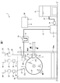
- FIG. 1 is a schematic view of a liquid application apparatus 1 according to a first embodiment of the present invention.
- the liquid application apparatus 1 applies a low viscosity liquid to one surface 3 ff of the web 3 being conveyed.
- the web 3 is composed of a bonding sheet in which an absorbent is attached to a top sheet of disposable diapers or a sanitary napkin at a constant interval in the transport direction MD.
- the web 3 is a product, semi-finished product or material of absorbent articles.
- Absorbent articles include paper diapers, sanitary napkins and the like.
- the liquid application device 1 includes a suction drum 5 (corresponding to a suction device).
- the suction drum 5 has a surface 5 f facing the other surface 3 fs of the web 3.
- the web 3 is sucked on the surface 5 f of the suction drum 5 and the liquid is applied on the surface 5 f of the suction drum 5.
- the structure and operation of the suction drum 5 will be described in detail later.
- the liquid application device 1 further includes an inlet roll 7a and an outlet roll 7b, which are, for example, free rolls having no drive source.
- the web 3 is guided by the inlet roll 7a to the suction drum 5, in particular onto the surface 5f of the suction drum 5, and by the outlet roll 7b to a post-processing step.
- the liquid application apparatus 1 includes a tank 11 for containing the liquid, and a liquid application nozzle 13 for applying the liquid to the sheet 3.
- the liquid application apparatus 1 further includes a pump 17 that supplies the liquid contained in the tank 11 to the liquid application nozzle 13 via the tube 15.
- the supply amount of the pump 17 can be changed.
- the tank 11 is disposed higher than the pump 17. As a result, the liquid in the tank 11 reaches the pump 17 by its own weight. Further, in the tube 15 between the tank 11 and the pump 17, a filter 19 for removing impurities mixed in the liquid is disposed.
- a liquid meter 21 is disposed in the portion of the tube 15 between the pump 17 and the liquid application nozzle 13.
- the liquid level meter 21 detects the amount of liquid flowing in the tube 15, that is, the amount of liquid actually applied to the sheet 3. Therefore, the amount of liquid actually applied to the sheet 3 can be easily detected.
- the amount of liquid supplied from the liquid application device 1 to the sheet 3 is very small, about 10 ml / min.
- the liquid flow meter 21 used in the first embodiment is a Coriolis flow meter. Coriolis flowmeters are suitable for measuring such small amounts of liquid.
- the fluid meter 21 is of another type.
- the Coriolis flowmeter is a flowmeter using the Coriolis force principle. That is, for example, when the tube is vibrated while a liquid to be measured flows in a U-shaped or straight tube, the tube is distorted. The magnitude of this strain depends on the flow rate of the liquid flowing in the tube. Therefore, if the magnitude of strain in the tube is detected, the liquid flow rate can be detected.
- the liquid application nozzle 13 includes a liquid jet passage (not shown), a pneumatically driven nozzle valve (not shown) for opening or closing the liquid jet passage, and an air chamber (not shown).
- a liquid jet passage (not shown)
- a pneumatically driven nozzle valve (not shown) for opening or closing the liquid jet passage
- an air chamber (not shown).
- the nozzle valve is opened and the liquid is ejected from the liquid flow passage.
- the nozzle valve is closed and the ejection of the liquid is stopped.
- the liquid application device 1 further comprises a first compressor 23.
- the air chamber of the liquid application nozzle 13 and the first compressor 23 are connected via a first air tube 25.
- a solenoid valve 27 for opening and closing a nozzle valve is disposed in the first air tube 25 between the liquid application nozzle 13 and the first compressor 23.
- the nozzle valve opening / closing solenoid valve 27 is opened, air pressure is applied to the liquid application nozzle 13 to open the nozzle valve.
- the nozzle valve opening / closing solenoid valve 27 is closed, the nozzle valve is closed.
- the liquid application nozzle 13 also includes an air flow passage (not shown) in communication with or adjacent to the liquid flow passage.
- the liquid application device 1 further comprises a second compressor 29.
- the air flow passage of the liquid application nozzle 13 is connected to the second compressor 29 via the second air tube 31.
- Another solenoid valve 33 and a regulator 35 for adjusting the air pressure in the second air tube 31 are attached to the second air tube 31.
- the solenoid valve 33 When the solenoid valve 33 is opened, compressed air is ejected from the air flow passage, so that the liquid ejected from the liquid flow passage via the outlet 13o is atomized and applied to the sheet 3.
- the solenoid valve 33 is closed, the supply of compressed air to the air flow passage is stopped.
- liquid is ejected from the liquid application nozzle 13 without using compressed air.
- liquid is applied to the web 3 by, for example, brushing or rollers.
- the liquid application nozzle 13 is provided with a single outlet 13o, which is directed perpendicularly to the center of the suction drum 5 and thus to one side 3ff of the web 3. It is done.
- the liquid ejected from the outlet 13o spreads in, for example, a conical shape with the outlet 13o at the top, and is applied to one surface 3ff of the web 3 with a certain area.
- the liquid application nozzle 13 is used to change the application range of the liquid to the web 3, particularly the application direction of the width direction CD of the web orthogonal to the transport direction MD (FIG. 3), using the existing liquid application nozzle 13.
- the distance between the outlet 13 o and one surface 3 ff of the web 3 is changed.
- the application time of a liquid is lengthened.
- the liquid application nozzle is provided with a plurality of outlets aligned with the width direction CD of the web 3 in order to widen the liquid coverage of the width direction CD (FIG. 3) of the web. .
- the application range of the liquid in the width direction CD of the web can be changed without changing the distance from the surface 5 f of the suction drum 5 of the liquid application nozzle 13.
- the liquid has a viscosity in the range of 0.05 to 4 Pa ⁇ s at least when applied to the sheet 3.
- the liquid has a viscosity in the range of 0.05 to 4 Pa ⁇ s at 20 to 25 ° C. and 1 atm.
- the liquid is a liquid having a higher viscosity than this.
- the liquid is a liquid having a lower viscosity.
- the liquid is, for example, petroleum hydrocarbon, animal and vegetable fat and oil, animal and vegetable wax, fatty acid ester compound, alkyl ethoxylate, fatty acid ester ethoxylate, fatty alcohol, polysiloxane and the like.
- the liquid is a pH adjuster, an antibacterial agent, an aromatic agent, a fragrance and the like.
- the liquid is intermittently applied, for example, to a portion corresponding to a longitudinally central portion of the disposable diaper, where the web is a combination sheet of the top sheet of the disposable diaper and the absorbent.
- the liquid is applied intermittently to another part of the disposable diaper or any part of another absorbent article.
- liquid is applied to the web 3 continuously from the liquid application device 1 in the transport direction MD.
- the liquid application device 1 further comprises an air blow nozzle 37.
- the air blow nozzle 37 blows air to the portion of the web 3 to which the liquid is applied, that is, blows air.
- the air blow nozzle 37 has a plurality of outlets 37 o aligned in the width direction CD of the web 3.
- the air outlet 37o of the air blow nozzle 37 is one.
- the liquid application device 1 further comprises another compressor 29 '.
- the air blow nozzle 37 includes an air flow passage (not shown) therein.
- the air flow passage of the air blow nozzle 37 is connected to another compressor 29 'via another air tube 31'. Attached to another air tube 31 'is another solenoid valve 33' and another regulator 35 'for adjusting the air pressure in the other air tube 31'.
- the solenoid valve 33 ' is opened, air is continuously blown out from the air flow passage through the air outlet 37o.
- the solenoid valve 33 ' is closed, the supply of compressed air to the air flow passage of the air blow nozzle 37 is stopped.
- the liquid application device 1 further comprises a controller 39.
- the controller 39 is constituted by, for example, a computer provided with a CPU (microprocessor), a memory, an input port, and an output port.
- a liquid meter 21 or the like is connected to the input port of the controller 39.
- the pump 17 and the nozzle valve opening / closing solenoid valve 27 etc. are connected to the output port of the controller 39.
- the pump 17 and the solenoid valve 27 are controlled based on a signal from the controller 39.
- the transport operation of the web 3 is controlled by the controller 39, and intermittent liquid ejection by the nozzle 13, specifically, the timing of opening and closing of the nozzle valve opening / closing solenoid valve 27. Synchronized with. As a result, the liquid can be applied to a desired location on one side 3ff of the web 3.
- FIG. 2 is an enlarged view of FIG. 1 at the periphery of the suction drum 5, and FIG. 3 is a cross-sectional view taken along the line III-III of FIG.
- the suction drum 5 includes a rotating portion 5r rotating with the drum shaft 5ds and a non-rotating non-rotating portion 5s located inside the suction drum 5, which are made of a hard material such as metal.
- the rotating portion 5r and the non-rotating portion 5s extend continuously in the rotational direction of the suction drum 5, respectively.
- the drum shaft 5ds is connected at one end (not shown) to a rotational drive device (not shown), which is, for example, a motor, and can rotate the rotating portion 5r of the suction drum 5 by its driving force.
- the radial direction RD means a direction orthogonal to the extending direction of the drum shaft 5ds.
- the rotating portion 5 r includes side portions 5 rs, an outer peripheral base 5 rc, and a mesh portion 5 rm.
- the side surface portion 5rs constituting one side surface of the suction drum 5 is connected at the other end 5dse of the drum shaft 5ds by a connecting means such as a bolt.
- the outer peripheral base portion 5rc, which constitutes the outer peripheral portion of the suction drum 5 together with the mesh portion 5rm, is connected to the radially outermost portion of the side surface portion 5rs by a connecting means such as a bolt.
- the mesh portion 5rm is formed by overlapping a plurality of mesh-like sheets, which are nets made of, for example, metal, resin material, and the like.
- the non-rotating portion 5s includes a hollow shaft 5ss and a side wall 5sw.
- the hollow shaft 5ss has a drum shaft 5ds inserted substantially coaxially in its hollow portion.
- a bearing 5br is provided between the outer peripheral surface of the drum shaft 5ds and the inner peripheral surface of the hollow shaft 5ss.
- the hollow shaft 5 ss is fixed, for example, to a wall (not shown) of the equipment so as not to rotate and to support the load of the entire suction drum 5.
- the hollow shaft 5 ss is connected on its outer peripheral surface to a side wall 5 sw expanding in the radial direction RD of the suction drum 5 between the outer surface of the hollow shaft 5 ss and the inner surface of the outer peripheral base 5 rc There is.
- a ring-shaped member 5sr made of, for example, felt is attached to the radially outermost portion of the side wall 5sw in contact with the inner peripheral surface of the outer peripheral base 5rc.
- the ring-shaped body 5 sr has a ring shape because it continuously extends in the rotational direction of the suction drum 5.
- the ring-shaped body 5 sr reduces the sliding resistance between the rotating outer peripheral base 5 rc and the non-rotating side wall 5 sw while securing a certain degree of airtightness.
- the material of the ring-shaped body 5sr is not limited to felt as long as it exhibits the above-mentioned function, and may be another material.
- a hollow portion 5h whose range is defined by the hollow shaft 5ss, the side wall 5sw, the ring-shaped body 5sr and the outer peripheral base 5rc is defined in the suction drum 5.
- an exhaust hole 5 swv is provided in the side wall 5 sw of the suction drum 5, and one end of the duct 41 is connected to the suction drum 5 in the exhaust hole 5 swv.
- the inside of the duct 41 communicates with the hollow portion 5h.
- the other end of the duct 41 is connected to an exhaust pump (not shown) for discharging the air in the hollow portion 5h in the direction F.
- one duct 41 and one exhaust pump are used.
- a plurality of exhaust holes 5swv are provided in the side wall 5sw, and the plurality of exhaust pumps are respectively connected with the suction drum 5 via the duct 41. By connecting, the suction amount can be increased.
- the outer peripheral base 5rc is provided with a large number of through holes 5rcp penetrating from the outer peripheral surface of the outer peripheral base 5rc to the inner peripheral surface.
- the through holes 5 rcp are provided to be substantially uniformly distributed on the surface of the outer peripheral base 5 rc.
- the through-hole 5rcp provided in the inner surface of outer periphery base 5rc is shown in FIG. 3, from the viewpoint of the legibility of a figure, only one part of these is shown in the same figure.
- the mesh portion 5 rm configured by a plurality of mesh-like sheets can pass air. Therefore, the hollow portion 5 h communicates with the outside of the suction drum 5.
- the exhaust pump (not shown) exhausts the air of the hollow portion 5h, while the hollow portion 5h receives the web 3 located on the mesh portion 5rm from the outside of the suction drum 5, and the mesh portion 5rm.
- the air is introduced through the through holes 5 rcp of the outer peripheral base 5 rc.
- the surface 5 f of the suction drum 5 facing the other surface 3 fs of the web 3 is the outer surface of the mesh portion 5 rm due to the configuration of the suction drum 5 described above.
- the suction drum 5 is provided with a screen 43 in contact with a part of the inner surface of the outer peripheral base 5rc inside the hollow portion 5h.
- the partition 43 is attached to the hollow shaft 5ss or the side wall 5sw by a jig (not shown).
- the contact portion between the partition 43 and the inner surface of the outer peripheral base 5rc is made of, for example, felt from the same effect as the ring-shaped member 5sr.
- the partitions 43 prevent the intake air from the outside of the suction drum 5 through the through holes 5 rcp of the outer peripheral base 5 rc in the contact portion.
- the surface 5f of the suction drum 5 is a length area along the outer periphery of the suction drum 5, a suction area AS for suctioning the web 3, and the web 3 and a non-suction area AN which does not suction.
- the suction drum 5 is not provided with the partition 43, and the surface 5f of the suction drum 5 is a suction area AS whose entire circumference sucks the web 3, and thus does not include the non-suction area AN. .
- the suction drum 5 sucks the web 3 in the suction area AS including the surface 5 f opposed to the surface 3 f on one side to which the liquid is applied and the other surface 3 f on the opposite side.
- the through holes 5 rcp are provided so as to be substantially uniformly distributed on the surface of the outer peripheral base 5 rc.
- the mesh portion 5rm having the above-described configuration is provided on the outer surface of the suction drum 5, the intake paths from the outside of the suction drum 5 to the respective through holes 5rcp are diverse. Therefore, on the surface 5f, the portion of the web 3 located in the suction area AS can be suctioned with substantially uniform suction regardless of the position.
- the suction drum 5 By the configuration of the suction drum 5 described above, the web 3 is attracted to the surface 5 f and held by being sucked by the suction drum 5. As a result, the web 3 is conveyed along with the rotation of the suction drum 5 and is conveyed by the suction drum 5 in the liquid application device 1 of the first embodiment.
- the web 3 of the first embodiment is a bonding sheet of the top sheet and the absorbent as described above, and generally does not include a low breathable material such as a plastic film contained in the back sheet of the absorbent article or the like. Therefore, the breathability of the web 3 is high and preferable.
- the air blowing direction of the air of the air blow nozzle 37 may be any direction as long as it contributes to impregnating the web 3 with the liquid.
- the direction in which the air is blown out from the air outlet 37o of the air blow nozzle 37 is directed to the transport direction MD side of the web 3 rather than the direction perpendicular to one surface 3ff of the web 3. ( ⁇ > 0 (see FIG. 2)).
- the air blow nozzle 37 blows out the air in this way, the web 3 does not move backward in the conveyance direction MD, so the air blow out direction is opposite to the conveyance direction MD of the web 3 ( ⁇ In contrast to ⁇ 0 (see FIG. 2), the web 3 is less likely to be wrinkled.
- the liquid applied to the surface of one surface 3ff of the web 3 is biased by the air in the transport direction MD, whereby the application range of the liquid can be expanded.
- the portion of the web 3 located in the suction area AS of the surface 5f of the suction drum 5 is held by the surface 5f by being suctioned with a substantially uniform suction force as a whole. It is transported. As a result, when the web 3 is transported, the occurrence of wrinkles and sags of the web 3 can be reduced, and the meandering of the web 3 can be suppressed.
- the suction area AS of the surface 5f of the suction drum 5 is at least a length area along the outer periphery of the suction drum 5 corresponding to the application range of the liquid by the liquid application nozzle 13 to the web 3.
- the liquid application area AA is included.
- the suction area AS of the surface 5 f of the suction drum 5 since sagging does not easily occur in the web 3, the liquid can be appropriately applied to the desired range of one surface 3 ff of the web 3.
- the suction area AS does not include the liquid application area AA.
- FIG. 4 is a diagram for illustrating the positional relationship between the suction drum 5, the liquid application nozzle 13 and the air blow nozzle 37 of the liquid application device 1 according to the first embodiment of the present invention. 4 is a view of the suction drum 5, the liquid application nozzle 13 and the air blow nozzle 37 as viewed in the direction in which the drum shaft 5ds of the suction drum 5 extends.
- the distance from the outlet 13o of the liquid application nozzle 13 to the surface 5f of the suction drum 5 is Lla
- the distance from the outlet 37o of the air blow nozzle 37 to the surface 5f of the suction drum 5 is Laf.
- the two distances Lla and Laf are Lla> Laf
- the air outlet 37 o of the air blow nozzle 37 be positioned closer to the surface 5 f of the suction drum 5 than the air outlet 13 o of the liquid application nozzle 13.
- the air blow nozzle 37 By positioning the air blow nozzle 37 closer to the surface 5 f of the suction drum 5 than the liquid application nozzle 13 and hence to one surface 3 ff of the web 3, turbulence of the air blow air flow is reduced, and higher pressure air can be obtained. Of the liquid applied to the web 3 can be impregnated by the thickness direction.
- the outlet 37o of the air blow nozzle 37 is farther from the surface 5f of the suction drum 5 than the outlet 13o of the liquid application nozzle 13, or these 13o, 37o are the surface 5f of the suction drum 5. Are positioned at the same distance from (Lla ⁇ Laf).
- the blowout port 13o of the liquid application nozzle 13 is a virtual line Lim extended in a direction to blow out air from the blowout port 37o of the air blow nozzle 37, and the outer peripheral surface 5f of the suction drum 5 (suction device
- the suction drum 5 is positioned closer to the outer circumferential surface 5 f of the suction drum 5 than the tangent Lta of the outer circumference of the suction drum 5 at the intersection point Pim with the surface 5 f).
- the air blown out from the air blow nozzle 37 strikes one surface 3 ff of the web 3. As a result, the collided air is diffused and reflected toward the air blow nozzle 37 more than at least the tangent Lta.
- the suction from the tangent Lta such that the outlet 13o of the liquid application nozzle 13 is not located in the area AF closer to the air blow nozzle 37 than the tangent Lta so that the direct reflection from the air blow nozzle 37 does not reach at least.
- the outlet 13o of the liquid application nozzle 13 is disposed in the area AC near the outer peripheral surface 5f of the drum.
- the outlet 13o of the liquid application nozzle 13 is at the intersection point Pim of the virtual line Lim extended in the direction in which the air is blown out from the outlet 37o of the air blow nozzle 37 and the outer peripheral surface 5f of the suction drum 5. It is positioned farther from the outer peripheral surface 5 f of the suction drum 5 than the tangent Lta of the outer periphery of the suction drum.
- FIG. 5 is a diagram showing the outer circumferences of the suction drum 5, the inlet roll 7a and the outlet roll 7b of the liquid application apparatus according to the first embodiment of the present invention.
- FIG. 5 is a view of the suction drum 5, the inlet roll 7a and the outlet roll 7b as viewed in the direction in which the drum shaft 5ds of the suction drum 5 extends.
- the contact point between the common tangent L1 of the outer periphery of the suction drum 5 and the inlet roll 7a and the outer periphery of the suction drum 5 is a first point P1, and the common tangent L2 of the outer periphery of the suction drum 5 and the outlet roll 7b.
- the point of contact between the two and the outer periphery of the suction drum 5 is taken as a second point P2.
- the surface 5f of the suction drum 5 has a length along the surface 5f of the suction drum 5 from the first point P1 to a second point P2 along the outer periphery in the reverse direction of the rotation direction R of the suction drum 5.
- non-suction area AN (FIG. 2) in which the web 3 is not suctioned in the thread area APP. If the web 3 is sucked by the suction drum 5 between the suction drum 5 and the inlet roll 7a and / or between the suction drum 5 and the outlet roll 7b, the web 3 is not conveyed linearly, It is because there is a possibility that conveyance of web 3 may not be performed normally.
- the area APP does not include the non-suction area AN.
- the range of the non-suction area AN (FIG. 2) is defined by the size and position of the partition 43 in the circumferential direction of the suction drum 5.
- the liquid application device 1 further includes a cover 45 in which the suction drum 5 and the liquid application nozzle 13 are accommodated. It is possible to prevent the liquid jetted from the liquid application nozzle 13 from scattering around, and to prevent the dust such as fiber debris flying from the outside of the liquid application device 1 from adhering to the web 3 It is.
- the cover 45 has a box-like shape in which the four sides and the upper side are surrounded. In another embodiment, the liquid application device 1 does not include the cover 45.
- At least one surface of the cover 45 is made of a transparent material so that the inside of the cover 45 can be viewed during use.
- the front surface of the cover 45 is made of a transparent material.
- the cover 45 is provided with a first opening 45 wf for carrying the web 3 into and out of the cover 45.
- the cover 45 be provided with a second opening 45 ws located vertically below the first opening 45 wf.
- the second opening 45 ws By providing the second opening 45 ws separately from the first opening 45 wf, more air can be introduced into the cover, and the intake efficiency from the outside of the suction drum 5 can be improved.
- the second opening 45 ws in the vertical direction lower than the first opening 45 wf, dust such as fiber waste that may fly up around the cover 45 is sucked into the cover 45. Can be suppressed.
- a plurality of second openings 45 ws can be provided on any surface of the cover 45 as long as the second openings 45 ws are vertically lower than the first opening 45 wf.
- the second opening 45 ws is provided with a filter (not shown) so as not to suction dust such as fiber waste.
- the cover 45 is not provided with the second opening 45 ws.
- FIG. 6 is an enlarged view of the periphery of the suction drum 5 of the schematic view of the liquid application apparatus 1 according to the modification of the first embodiment of the present invention, similar to FIG.
- the liquid application device 1 includes a plurality of, specifically, four air blow nozzles 37a, 37b, 37c, and 37d. Although not shown, compressed air is commonly supplied to the air blow nozzles 37a, 37b, 37c and 37d from another compressor 29 '(FIG. 1).
- liquid application device 1 of this modification is provided with a plurality of air blow nozzles 37a, 37b, 37c, 37d which perform air blow a plurality of times under relatively low air pressure. As a result, air is blown to the web 3 in stages without interfering with the stable transport of the web 3, and as a result, the liquid can be sufficiently impregnated in the thickness direction of the web 3.
- the liquid application device 1 includes the plurality of air blow nozzles 37a, 37b, 37c, 37d, whereby the web sequentially transported on the surface 5f of the suction drum 5 The air blowing time can be extended for the part 3. As a result, even when the transport speed of the web 3 is high, the liquid applied to the web 3 can be more fully impregnated in the thickness direction of the web 3.
- FIG. 7 is a view on arrow VII of FIG. It should be noted that in FIG. 7 the description of the two air blow nozzles 37c, 37d is omitted for ease of explanation.
- the blowout ports 37ao and 37bo of the air blow nozzles 37a and 37b are respectively aligned in the width direction CD of the web 3 perpendicular to the transport direction MD, and the air blow nozzles 37a and 37b are It is preferable that the outlets 37ao and 37bo of the air blow nozzles 37a and 37b adjacent in the transport direction MD be positioned to be offset in the width direction CD of the web 3 for the following reason.
- FIG. 7 the structure which offsets these blower outlets 37ao and 37bo using two air blow nozzles 37a, 37b was shown.
- three adjacent air blow nozzles 37a, 37b, and 37c, and these air outlets 37o each have a width of the web 3 in order to reduce the portion of the web 3 to which air is not blown. It can also be positioned so as to offset each other in the direction CD, in other words, in a zigzag manner in the transport direction MD.
- adjacent air blow nozzles 37a, 37b, 37c and 37d are arbitrarily combined to reduce the portion of the web 3 to which the air is not blown, and the positions of these blowouts 37o are in the width direction of the web 3. It can be positioned to be offset to the CD.
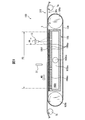
- FIG. 8 is a schematic partial cross-sectional view of a liquid application apparatus 100 according to a second embodiment of the present invention.
- the mechanism for ejecting the liquid from the liquid application nozzle 13 and the mechanism for ejecting the air from the air blow nozzle 37 are the same as those in FIG.
- the second embodiment is mainly different from the first embodiment in that the web 3 is sucked using a suction box 105 (corresponding to a suction device) instead of the suction drum 5 (FIG. 1, etc.).
- the web 3 is transported in the transport direction MD by the transport devices 107 a and 107 b on the surface 105 f on the upper side in the vertical direction of the suction box 105. Then, as in the first embodiment, a low viscosity liquid is applied to one surface 3 ff of the web 3 being conveyed using the liquid application nozzle 13, and then the liquid is discharged using the air blow nozzle 37. Air blow is performed on the portion of the applied web 3.
- the suction box 105 is in the form of a rectangular parallelepiped as a whole, and includes a main body portion 105b forming an outer shell portion of the suction box 105 and a hollow portion 105h located inside the main body portion 105b.
- an exhaust hole 105bv is provided in the lower portion 105bl of the main body portion 105b of the suction box 105, and one end of the duct 41 is connected to the suction box 105 at the exhaust hole 105bv. .
- the inside of the duct 41 is in communication with the hollow portion 105 h.
- the other end of the duct 41 is connected to an exhaust pump (not shown) for discharging the air of the hollow portion 105 h in the direction F.
- the suction amount is provided by providing the plurality of exhaust holes 105bv in the main body portion 105b and connecting the plurality of exhaust pumps to the suction box 105 via the duct 41, respectively. Can be increased.
- the upper portion 105bu of the main body portion 105b is provided with a large number of through holes 105bp.
- the through holes 105bp are provided substantially uniformly distributed over the entire surface of the upper portion 105bu.
- a mesh portion 105m similar to the mesh portion 5rm of the first embodiment is provided on the upper surface of the suction box 105 in the vertical direction.
- seat can pass air. Therefore, the hollow portion 105 h is in communication with the outside of the suction box 105.
- the surface 105 f of the suction box 105 facing the other surface 3 fs of the web 3 is the outer surface of the mesh portion 105 m due to the above-described configuration of the suction box 105.
- the surface 105 f of the suction box 105 can suction the web 3, which is a length area of the surface 105 f in the range where the through holes 105 bp are provided. Includes area AS.
- the web 3 is different from the first embodiment in that the web 3 slides on the surface 105 f of the suction box 105.
- the suction box 105 is conveyed while being suctioned with a substantially uniform suction force as a whole.
- the occurrence of wrinkles and sags of the web 3 can be reduced, and in turn, the meandering of the web 3 can be suppressed.
- the suction area AS is at least a length area of the surface 105 f of the suction box 105 and includes the liquid application area AA to which the liquid is applied.
- the suction area AS of the surface 5 f of the suction drum 5 since sagging does not easily occur in the web 3, the liquid can be appropriately applied to the desired area of one surface 3 ff of the web 3.
- the suction area AS does not include the liquid application area AA.
- the outlet 37o of the air blow nozzle 37 is positioned closer to the surface 5f of the suction drum 5 than the outlet 13o of the liquid application nozzle 13. Is preferred.
- FIG. 9 is a partial cross-sectional schematic view of a liquid application apparatus 100 according to a modification of the second embodiment of the present invention, similar to FIG.
- the liquid application device 100 further includes a mesh belt 109.
- the mesh belt 109 is wound around a pair of rollers 109 a and 109 b around the suction box 105.
- the mesh belt 109 is a breathable endless belt formed of a mesh-like sheet, which is a net made of a material such as metal or resin.
- At least one of the pair of rollers 109a and 109b is rotationally driven by a drive source, for example, a servomotor (not shown) so that the mesh belt 109 moves in the transport direction MD on the surface 105f of the suction box 105. Ru.
- a drive source for example, a servomotor (not shown) so that the mesh belt 109 moves in the transport direction MD on the surface 105f of the suction box 105.
- an exhaust hole 105bv is provided in one side portion 105bs of the main body portion 105b, and one end of the duct is an exhaust hole so that the suction belt 109 and the duct (not shown) do not interfere. Connected to 105bv. The other end of the duct is connected to an exhaust pump (not shown).
- the liquid application apparatus 100 of the present modification includes an inlet roll 7a and an outlet roll 7b.
- the web 3 is guided on the mesh belt 109 by the inlet roll 7a and is guided to the post-process by the outlet roll 7b.
- the web 3 located on the mesh belt 109 is sucked and held on the outer surface of the mesh belt 109 by being sucked by the suction box 105 in the suction area AS. As a result, the web 3 is conveyed along with the movement of the mesh belt 109, and is conveyed by the mesh belt 109 in the liquid application device 100 of the present modification.
- the portion of the web 3 located above the suction area AS of the surface 105f of the suction box 105 is held on the outer surface of the mesh belt 109 by being suctioned with a substantially uniform suction force as a whole. It is transported while. As a result, the occurrence of wrinkles and sags during transport can be reduced, which in turn can suppress the meandering of the web 3.
- the liquid application device 100 according to the second embodiment does not include the cover 45 provided in the liquid application device 1 according to the first embodiment.
- a modified embodiment in which the liquid application apparatus 100 according to the second embodiment includes the cover 45 that houses the liquid application nozzle 13 and the suction box 105 is also included in the scope of the present invention.
- the liquid application device 100 according to the second embodiment includes one air blow nozzle 37, but includes a plurality of air blow nozzles 37, for example, as in the modification of the first embodiment.
- Such modified embodiments are also included in the scope of the present invention.
- adjacent air blow nozzles 37 are positioned such that their outlets 37 o are mutually offset in the width direction CD of the web 3.
- Such modified embodiments are also included in the scope of the present invention.
- the present invention is defined as follows.
- a liquid application apparatus for applying a liquid having a viscosity in the range of 0.05 to 4 Pa ⁇ s to a continuously conveyed web used for producing an absorbent article, A tank for containing the liquid; A liquid application nozzle for applying the liquid to one side of the web; A pump for supplying the liquid in the tank to the liquid application nozzle through a tube; A suction device having a surface facing the other side of the web; An air blow nozzle for blowing air to a portion to which liquid is applied on the one surface of the web; Equipped with The surface of the suction device at least includes a suction area for suctioning the web, Liquid application device.
- the suction device is a suction drum
- the surface of the suction device is an outer peripheral surface of the suction drum
- the suction port of the liquid application nozzle is the suction line rather than a tangent of the outer periphery of the suction drum at an intersection point of a virtual line extended in a direction to blow air from the blow port of the air blow nozzle and the outer peripheral surface of the suction drum.
- the liquid application apparatus as described in (1) or (2).
- the surface of the suction device has a first point of contact between the common tangent of the outer periphery of the suction drum and the inlet roll and the outer periphery of the suction drum as a first point, and the common tangent of the outer periphery of the suction drum and the outlet roll
- the point of contact with the outer periphery of the suction drum is a second point
- the web is placed in a region from the first point to the second point along the outer periphery in the direction opposite to the rotation direction of the suction drum.
- the suction device is a suction box,
- the surface of the suction device is the surface above the suction box in the vertical direction,
- the web is conveyed on the surface of the suction box while being sucked by the suction box.
- the liquid application apparatus as described in (1) or (2).
- the mesh box further comprises a mesh belt wound around the suction box, The web is transported with the movement of the mesh belt.
- the liquid application apparatus as described in (6).
- a plurality of air blow nozzles are provided, The liquid application apparatus as described in any one of (1) to (7).
- Each of the air blow nozzles is provided with a plurality of outlets.
- the liquid application apparatus as described in any one of (1) to (10).
- a liquid application method of applying a liquid having a viscosity in the range of 0.05 to 4 Pa ⁇ s to a continuously conveyed web used for producing an absorbent article A tank for containing the liquid; A liquid application nozzle for applying the liquid to one side of the web; A pump for supplying the liquid in the tank to the liquid application nozzle through a tube; A suction device having a surface facing the other side of the web; An air blow nozzle for blowing air to a portion of the one surface of the web to which the liquid is applied; Equipped with The surface of the suction device at least includes a suction area for suctioning the web, Providing a liquid application device; Suctioning the web in the suction area by the suction device; Applying the liquid to the web by the liquid application nozzle; Air blowing the web with the air blow nozzle; including, Liquid application method.
Landscapes
- Health & Medical Sciences (AREA)
- Engineering & Computer Science (AREA)
- Life Sciences & Earth Sciences (AREA)
- Biomedical Technology (AREA)
- Manufacturing & Machinery (AREA)
- Epidemiology (AREA)
- Heart & Thoracic Surgery (AREA)
- Vascular Medicine (AREA)
- Animal Behavior & Ethology (AREA)
- General Health & Medical Sciences (AREA)
- Public Health (AREA)
- Veterinary Medicine (AREA)
- Botany (AREA)
- Absorbent Articles And Supports Therefor (AREA)
Abstract
Description
吸収性物品の製造に用いられる、連続的に搬送されているウェブに対して、0.05~4Pa・sの範囲の粘度を有する液体を適用する液体適用装置であって、
前記液体を収容するタンクと、
前記液体を前記ウェブの一方の面に対して適用する液体適用ノズルと、
前記タンク内の液体を、チューブを介して前記液体適用ノズルに供給するポンプと、
前記ウェブの他方の面に対面する表面を有する吸引装置と、
前記ウェブの前記一方の面の、液体が適用された部分に対して、エアブローを行うエアブローノズルと、
を備え、
前記吸引装置の前記表面は、前記ウェブを吸引する吸引領域を少なくとも含む、
液体適用装置が提供される。 In order to solve the above-mentioned problems, according to the present invention,
A liquid application apparatus for applying a liquid having a viscosity in the range of 0.05 to 4 Pa · s to a continuously conveyed web used for producing an absorbent article,
A tank for containing the liquid;
A liquid application nozzle for applying the liquid to one side of the web;
A pump for supplying the liquid in the tank to the liquid application nozzle through a tube;
A suction device having a surface facing the other side of the web;
An air blow nozzle for blowing air to a portion to which liquid is applied on the one surface of the web;
Equipped with
The surface of the suction device at least includes a suction area for suctioning the web,
A liquid application device is provided.
吸収性物品の製造に用いられる、連続的に搬送されているウェブに対して、0.05~4Pa・sの範囲の粘度を有する液体を適用する液体適用方法であって、
前記液体を収容するタンクと、
前記液体を前記ウェブの一方の面に対して適用する液体適用ノズルと、
前記タンク内の液体を、チューブを介して前記液体適用ノズルに供給するポンプと、
前記ウェブの他方の面に対面する表面を有する吸引装置と、
前記ウェブの前記一方の面の、前記液体が適用された部分に対して、エアブローを行うエアブローノズルと、
を備え、
前記吸引装置の前記表面は、前記ウェブを吸引する吸引領域を少なくとも含む、
液体適用装置を用意する工程と、
前記吸引装置によって、前記吸引領域において前記ウェブを吸引する工程と、
前記液体適用ノズルによって、前記ウェブに前記液体を適用する工程と、
前記エアブローノズルによって、前記ウェブにエアブローを行う工程と、
を含む、
液体適用方法が提供される。 Furthermore, in order to solve the above problems, according to the present invention,
A liquid application method of applying a liquid having a viscosity in the range of 0.05 to 4 Pa · s to a continuously conveyed web used for producing an absorbent article,
A tank for containing the liquid;
A liquid application nozzle for applying the liquid to one side of the web;
A pump for supplying the liquid in the tank to the liquid application nozzle through a tube;
A suction device having a surface facing the other side of the web;
An air blow nozzle for blowing air to a portion of the one surface of the web to which the liquid is applied;
Equipped with
The surface of the suction device at least includes a suction area for suctioning the web,
Providing a liquid application device;
Suctioning the web in the suction area by the suction device;
Applying the liquid to the web by the liquid application nozzle;
Air blowing the web with the air blow nozzle;
including,
A liquid application method is provided.
これより、図1から図5を参照しつつ、本発明の第一の実施形態の液体適用装置1を説明する。 (First embodiment)
The liquid application apparatus 1 according to the first embodiment of the present invention will be described with reference to FIGS. 1 to 5.
粘度(Pa・s)=動粘度(m2/s)×密度(kg/m3) The viscosity of the liquid is detected as follows. At a desired temperature, the kinematic viscosity is detected by a Canon-Fenske viscometer according to JIS K 2283, and the density is further detected by a vibrating density meter according to JIS K 2249. From the above results, the viscosity at that temperature is calculated using the following equation.
Viscosity (Pa · s) = Kinetical viscosity (m 2 / s) × density (kg / m 3 )
Lla>Laf
の関係を満たすと、すなわち、エアブローノズル37の吹出口37oが、液体適用ノズル13の吹出口13oよりも、サクションドラム5の表面5fの近くに位置決めされていると好ましい。エアブローノズル37が液体適用ノズル13よりもサクションドラム5の表面5fの近く、ひいてはウェブ3の一方の面3ffの近くに位置決めされることにより、エアブローの気流の乱れを減少させて、より高圧のエアをウェブ3に吹付けることができ、ひいてはウェブ3に適用された液体をその厚さ方向により含浸させることができるからである。別の実施形態では、エアブローノズル37の吹出口37oが、液体適用ノズル13の吹出口13oよりも、サクションドラム5の表面5fの遠くに、又は、これら13o、37oが、サクションドラム5の表面5fから同じ距離で位置決めされている(Lla≦Laf)。 As shown in FIG. 4, the distance from the outlet 13o of the
Lla> Laf
It is preferable that the air outlet 37 o of the
これより、図6及び図7を用いて、本発明の第一の実施形態の変形例を説明する。図6は、図2に類似する、本発明の第一の実施形態の変形例に係る液体適用装置1の概略図のサクションドラム5の周辺における拡大図である。本変形例では、液体適用装置1は、複数の、具体的には4つのエアブローノズル37a、37b、37c、37dを備える。なお、特に図示はしないが、各エアブローノズル37a、37b、37c、37dは、別のコンプレッサ29’(図1)から共通して、圧縮空気が供給されている。 (Modification)
A modification of the first embodiment of the present invention will now be described using FIGS. 6 and 7. FIG. 6 is an enlarged view of the periphery of the
これより、図8を用いて、本発明の第二の実施形態の液体適用装置100を説明する。なお、第二の実施形態については、第一の実施形態との差異点が特に説明される。また、第一の実施形態における第二の実施形態との差異点以外の構成要素は、第二の実施形態に適用可能であり、当業者は自明の範囲内でこれら構成要素を任意に組み合わせることができる。 Second Embodiment
The
これより、図9を用いて、本発明の第二の実施形態の変形例を説明する。図9は、図8に類似する、本発明の第二の実施形態の変形例に係る液体適用装置100の部分断面概略図である。本変形例では、液体適用装置100はさらにメッシュベルト109含む。 (Modification)
A modification of the second embodiment of the present invention will now be described using FIG. FIG. 9 is a partial cross-sectional schematic view of a
前記液体を収容するタンクと、
前記液体を前記ウェブの一方の面に対して適用する液体適用ノズルと、
前記タンク内の液体を、チューブを介して前記液体適用ノズルに供給するポンプと、
前記ウェブの他方の面に対面する表面を有する吸引装置と、
前記ウェブの前記一方の面の、液体が適用された部分に対して、エアブローを行うエアブローノズルと、
を備え、
前記吸引装置の前記表面は、前記ウェブを吸引する吸引領域を少なくとも含む、
液体適用装置。 (1) A liquid application apparatus for applying a liquid having a viscosity in the range of 0.05 to 4 Pa · s to a continuously conveyed web used for producing an absorbent article,
A tank for containing the liquid;
A liquid application nozzle for applying the liquid to one side of the web;
A pump for supplying the liquid in the tank to the liquid application nozzle through a tube;
A suction device having a surface facing the other side of the web;
An air blow nozzle for blowing air to a portion to which liquid is applied on the one surface of the web;
Equipped with
The surface of the suction device at least includes a suction area for suctioning the web,
Liquid application device.
(1)に記載の液体適用装置。 (2) The outlet of the air blow nozzle is positioned closer to the surface of the suction device than the outlet of the liquid application nozzle.
The liquid application apparatus as described in (1).
前記吸引装置の前記表面は、前記サクションドラムの外周面であり、
前記液体適用ノズルの吹出口は、前記エアブローノズルの吹出口からエアを吹出す方向に延ばした仮想線と、前記サクションドラムの外周面との交点における前記サクションドラムの外周の接線よりも、前記サクションドラムの外周面の近くに位置決めされている、
(1)又は(2)に記載の液体適用装置。 (3) The suction device is a suction drum,
The surface of the suction device is an outer peripheral surface of the suction drum,
The suction port of the liquid application nozzle is the suction line rather than a tangent of the outer periphery of the suction drum at an intersection point of a virtual line extended in a direction to blow air from the blow port of the air blow nozzle and the outer peripheral surface of the suction drum. Positioned near the outer circumferential surface of the drum,
The liquid application apparatus as described in (1) or (2).
(3)に記載の液体適用装置。 (4) The web is conveyed along with the rotation of the suction drum while being sucked by the rotationally driven suction drum.
The liquid application apparatus as described in (3).
前記吸引装置の前記表面は、前記サクションドラム及び前記入口ロールの外周の共通接線と前記サクションドラムの外周との接点を第一の点とし、前記サクションドラム及び前記出口ロールの外周の共通接線と前記サクションドラムの外周との接点を第二の点としたときに、前記第一の点から前記サクションドラムの回転方向の逆方向に外周に沿った前記第二の点までの領域に、前記ウェブを吸引しないようにされた非吸引領域を含む、
(4)に記載の液体適用装置。 (5) further comprising: an inlet roll for guiding the web to the suction drum; and an outlet roll for guiding the web from the suction drum to a subsequent process,
The surface of the suction device has a first point of contact between the common tangent of the outer periphery of the suction drum and the inlet roll and the outer periphery of the suction drum as a first point, and the common tangent of the outer periphery of the suction drum and the outlet roll When the point of contact with the outer periphery of the suction drum is a second point, the web is placed in a region from the first point to the second point along the outer periphery in the direction opposite to the rotation direction of the suction drum. Including a non-suction area which is set to not suction
The liquid application apparatus as described in (4).
前記吸引装置の前記表面は、前記サクションボックスの鉛直方向上側の表面であり、
前記ウェブは、前記サクションボックスによって吸引されつつ、前記サクションボックスの前記表面の上で搬送される、
(1)又は(2)に記載の液体適用装置。 (6) The suction device is a suction box,
The surface of the suction device is the surface above the suction box in the vertical direction,
The web is conveyed on the surface of the suction box while being sucked by the suction box.
The liquid application apparatus as described in (1) or (2).
前記ウェブは、前記メッシュベルトの移動と共に搬送される、
(6)に記載の液体適用装置。 (7) The mesh box further comprises a mesh belt wound around the suction box,
The web is transported with the movement of the mesh belt.
The liquid application apparatus as described in (6).
(1)から(7)のいずれか1つに記載の液体適用装置。 (8) A plurality of air blow nozzles are provided,
The liquid application apparatus as described in any one of (1) to (7).
前記エアブローノズルは、隣り合う前記エアブローノズルの吹出口が前記幅方向にオフセットするように位置決めされている、
(8)に記載の液体適用装置。 (9) The outlets of the air blow nozzles are aligned in the width direction of the web perpendicular to the transport direction,
The air blow nozzle is positioned such that the outlets of the adjacent air blow nozzles are offset in the width direction.
The liquid application apparatus as described in (8).
(1)から(9)のいずれか1つに記載の液体適用装置。 (10) The direction in which the air is blown out from the blowout port of the air blow nozzle is directed to the side of the web in the transport direction rather than the direction perpendicular to the one surface of the web.
The liquid application apparatus as described in any one of (1) to (9).
(1)から(10)のいずれか1つに記載の液体適用装置。 (11) Each of the air blow nozzles is provided with a plurality of outlets.
The liquid application apparatus as described in any one of (1) to (10).
前記液体を収容するタンクと、
前記液体を前記ウェブの一方の面に対して適用する液体適用ノズルと、
前記タンク内の液体を、チューブを介して前記液体適用ノズルに供給するポンプと、
前記ウェブの他方の面に対面する表面を有する吸引装置と、
前記ウェブの前記一方の面の、前記液体が適用された部分に対して、エアブローを行うエアブローノズルと、
を備え、
前記吸引装置の前記表面は、前記ウェブを吸引する吸引領域を少なくとも含む、
液体適用装置を用意する工程と、
前記吸引装置によって、前記吸引領域において前記ウェブを吸引する工程と、
前記液体適用ノズルによって、前記ウェブに前記液体を適用する工程と、
前記エアブローノズルによって、前記ウェブにエアブローを行う工程と、
を含む、
液体適用方法。 (12) A liquid application method of applying a liquid having a viscosity in the range of 0.05 to 4 Pa · s to a continuously conveyed web used for producing an absorbent article,
A tank for containing the liquid;
A liquid application nozzle for applying the liquid to one side of the web;
A pump for supplying the liquid in the tank to the liquid application nozzle through a tube;
A suction device having a surface facing the other side of the web;
An air blow nozzle for blowing air to a portion of the one surface of the web to which the liquid is applied;
Equipped with
The surface of the suction device at least includes a suction area for suctioning the web,
Providing a liquid application device;
Suctioning the web in the suction area by the suction device;
Applying the liquid to the web by the liquid application nozzle;
Air blowing the web with the air blow nozzle;
including,
Liquid application method.
3 ウェブ
3ff 一方の面
3fs 他方の面
5 サクションドラム(吸引装置)
5f 表面
11 タンク
13 液体適用ノズル
15 チューブ
17 ポンプ
37、37a、37b、37c、37d エアブローノズル
105 サクションボックス(吸引装置)
105f 表面
AS 吸引領域 1, 100
105f Surface AS suction area
Claims (12)
- 吸収性物品の製造に用いられる、連続的に搬送されているウェブに対して、0.05~4Pa・sの範囲の粘度を有する液体を適用する液体適用装置であって、
前記液体を収容するタンクと、
前記液体を前記ウェブの一方の面に対して適用する液体適用ノズルと、
前記タンク内の液体を、チューブを介して前記液体適用ノズルに供給するポンプと、
前記ウェブの他方の面に対面する表面を有する吸引装置と、
前記ウェブの前記一方の面の、液体が適用された部分に対して、エアブローを行うエアブローノズルと、
を備え、
前記吸引装置の前記表面は、前記ウェブを吸引する吸引領域を少なくとも含む、
液体適用装置。 A liquid application apparatus for applying a liquid having a viscosity in the range of 0.05 to 4 Pa · s to a continuously conveyed web used for producing an absorbent article,
A tank for containing the liquid;
A liquid application nozzle for applying the liquid to one side of the web;
A pump for supplying the liquid in the tank to the liquid application nozzle through a tube;
A suction device having a surface facing the other side of the web;
An air blow nozzle for blowing air to a portion to which liquid is applied on the one surface of the web;
Equipped with
The surface of the suction device at least includes a suction area for suctioning the web,
Liquid application device. - 前記エアブローノズルの吹出口は、前記液体適用ノズルの吹出口よりも、前記吸引装置の前記表面の近くに位置決めされている、
請求項1に記載の液体適用装置。 The outlet of the air blow nozzle is positioned closer to the surface of the suction device than the outlet of the liquid application nozzle.
The liquid application device according to claim 1. - 前記吸引装置は、サクションドラムであり、
前記吸引装置の前記表面は、前記サクションドラムの外周面であり、
前記液体適用ノズルの吹出口は、前記エアブローノズルの吹出口からエアを吹出す方向に延ばした仮想線と、前記サクションドラムの外周面との交点における前記サクションドラムの外周の接線よりも、前記サクションドラムの外周面の近くに位置決めされている、
請求項1又は2に記載の液体適用装置。 The suction device is a suction drum,
The surface of the suction device is an outer peripheral surface of the suction drum,
The suction port of the liquid application nozzle is the suction line rather than a tangent of the outer periphery of the suction drum at an intersection point of a virtual line extended in a direction to blow air from the blow port of the air blow nozzle and the outer peripheral surface of the suction drum. Positioned near the outer circumferential surface of the drum,
The liquid application apparatus according to claim 1. - 前記ウェブは、回転駆動される前記サクションドラムで吸引されつつ、前記サクションドラムの回転と共に搬送される、
請求項3に記載の液体適用装置。 The web is conveyed along with the rotation of the suction drum while being sucked by the rotationally driven suction drum.
The liquid application apparatus according to claim 3. - 前記ウェブを前記サクションドラムにガイドする入口ロールと、前記ウェブを前記サクションドラムから後工程にガイドする出口ロールとをさらに備え、
前記吸引装置の前記表面は、前記サクションドラム及び前記入口ロールの外周の共通接線と前記サクションドラムの外周との接点を第一の点とし、前記サクションドラム及び前記出口ロールの外周の共通接線と前記サクションドラムの外周との接点を第二の点としたときに、前記第一の点から前記サクションドラムの回転方向の逆方向に外周に沿った前記第二の点までの領域に、前記ウェブを吸引しないようにされた非吸引領域を含む、
請求項4に記載の液体適用装置。 It further comprises an inlet roll for guiding the web to the suction drum, and an outlet roll for guiding the web from the suction drum to a later process.
The surface of the suction device has a first point of contact between the common tangent of the outer periphery of the suction drum and the inlet roll and the outer periphery of the suction drum as a first point, and the common tangent of the outer periphery of the suction drum and the outlet roll When the point of contact with the outer periphery of the suction drum is a second point, the web is placed in a region from the first point to the second point along the outer periphery in the direction opposite to the rotation direction of the suction drum. Including a non-suction area which is set to not suction
The liquid application device according to claim 4. - 前記吸引装置は、サクションボックスであり、
前記吸引装置の前記表面は、前記サクションボックスの鉛直方向上側の表面であり、
前記ウェブは、前記サクションボックスによって吸引されつつ、前記サクションボックスの前記表面の上で搬送される、
請求項1又は2に記載の液体適用装置。 The suction device is a suction box,
The surface of the suction device is the surface above the suction box in the vertical direction,
The web is conveyed on the surface of the suction box while being sucked by the suction box.
The liquid application apparatus according to claim 1. - 前記サクションボックスの周囲に掛け回されたメッシュベルトをさらに備え、
前記ウェブは、前記メッシュベルトの移動と共に搬送される、
請求項6に記載の液体適用装置。 The mesh box further comprises a mesh belt wound around the suction box,
The web is transported with the movement of the mesh belt.
The liquid application apparatus according to claim 6. - 前記エアブローノズルが複数設けられている、
請求項1から7のいずれか1項に記載の液体適用装置。 A plurality of the air blow nozzles are provided,
The liquid application apparatus according to any one of claims 1 to 7. - 前記エアブローノズルの吹出口は、搬送方向に対して垂直な前記ウェブの幅方向に整列しており、
前記エアブローノズルは、隣り合う前記エアブローノズルの吹出口が前記幅方向にオフセットするように位置決めされている、
請求項8に記載の液体適用装置。 The outlets of the air blow nozzles are aligned in the width direction of the web perpendicular to the transport direction,
The air blow nozzle is positioned such that the outlets of the adjacent air blow nozzles are offset in the width direction.
The liquid application apparatus according to claim 8. - 前記エアブローノズルの吹出口からエアを吹出す方向は、前記ウェブの前記一方の面に対して垂直な方向よりも、前記ウェブの搬送方向側を向いている、
請求項1から9のいずれか1項に記載の液体適用装置。 The direction in which the air is blown out from the air outlet of the air blow nozzle is directed to the side of the web in the transport direction rather than the direction perpendicular to the one surface of the web.
The liquid application apparatus according to any one of claims 1 to 9. - 前記エアブローノズルのそれぞれには、複数の吹出口が設けられている、
請求項1から10のいずれか1項に記載の液体適用装置。 Each of the air blow nozzles is provided with a plurality of outlets.
The liquid application apparatus according to any one of claims 1 to 10. - 吸収性物品の製造に用いられる、連続的に搬送されているウェブに対して、0.05~4Pa・sの範囲の粘度を有する液体を適用する液体適用方法であって、
前記液体を収容するタンクと、
前記液体を前記ウェブの一方の面に対して適用する液体適用ノズルと、
前記タンク内の液体を、チューブを介して前記液体適用ノズルに供給するポンプと、
前記ウェブの他方の面に対面する表面を有する吸引装置と、
前記ウェブの前記一方の面の、前記液体が適用された部分に対して、エアブローを行うエアブローノズルと、
を備え、
前記吸引装置の前記表面は、前記ウェブを吸引する吸引領域を少なくとも含む、
液体適用装置を用意する工程と、
前記吸引装置によって、前記吸引領域において前記ウェブを吸引する工程と、
前記液体適用ノズルによって、前記ウェブに前記液体を適用する工程と、
前記エアブローノズルによって、前記ウェブにエアブローを行う工程と、
を含む、
液体適用方法。 A liquid application method of applying a liquid having a viscosity in the range of 0.05 to 4 Pa · s to a continuously conveyed web used for producing an absorbent article,
A tank for containing the liquid;
A liquid application nozzle for applying the liquid to one side of the web;
A pump for supplying the liquid in the tank to the liquid application nozzle through a tube;
A suction device having a surface facing the other side of the web;
An air blow nozzle for blowing air to a portion of the one surface of the web to which the liquid is applied;
Equipped with
The surface of the suction device at least includes a suction area for suctioning the web,
Providing a liquid application device;
Suctioning the web in the suction area by the suction device;
Applying the liquid to the web by the liquid application nozzle;
Air blowing the web with the air blow nozzle;
including,
Liquid application method.
Priority Applications (3)
| Application Number | Priority Date | Filing Date | Title |
|---|---|---|---|
| KR1020157021782A KR102047581B1 (en) | 2013-07-22 | 2014-06-30 | Liquid application device and liquid application method |
| IN363DEN2015 IN2015DN00363A (en) | 2013-07-22 | 2014-06-30 | |
| CN201480001999.XA CN104519845B (en) | 2013-07-22 | 2014-06-30 | Liquid bringing device and liquid applying method |
Applications Claiming Priority (2)
| Application Number | Priority Date | Filing Date | Title |
|---|---|---|---|
| JP2013-151698 | 2013-07-22 | ||
| JP2013151698A JP5748807B2 (en) | 2013-07-22 | 2013-07-22 | Liquid application apparatus and liquid application method |
Publications (1)
| Publication Number | Publication Date |
|---|---|
| WO2014196664A1 true WO2014196664A1 (en) | 2014-12-11 |
Family
ID=52008288
Family Applications (1)
| Application Number | Title | Priority Date | Filing Date |
|---|---|---|---|
| PCT/JP2014/067388 WO2014196664A1 (en) | 2013-07-22 | 2014-06-30 | Liquid application device and liquid application method |
Country Status (6)
| Country | Link |
|---|---|
| JP (1) | JP5748807B2 (en) |
| KR (1) | KR102047581B1 (en) |
| CN (1) | CN104519845B (en) |
| IN (1) | IN2015DN00363A (en) |
| TW (1) | TWI636774B (en) |
| WO (1) | WO2014196664A1 (en) |
Cited By (1)
| Publication number | Priority date | Publication date | Assignee | Title |
|---|---|---|---|---|
| CN107106349A (en) * | 2014-12-25 | 2017-08-29 | 尤妮佳股份有限公司 | The manufacture method of absorbent commodity and the manufacture device of absorbent commodity |
Families Citing this family (2)
| Publication number | Priority date | Publication date | Assignee | Title |
|---|---|---|---|---|
| JP5748806B2 (en) * | 2013-07-22 | 2015-07-15 | ユニ・チャーム株式会社 | Liquid application apparatus and liquid application method |
| JP7094240B2 (en) * | 2019-04-01 | 2022-07-01 | ユニ・チャーム株式会社 | How to make an absorbent article |
Citations (6)
| Publication number | Priority date | Publication date | Assignee | Title |
|---|---|---|---|---|
| US5711994A (en) * | 1995-12-08 | 1998-01-27 | Kimberly-Clark Worldwide, Inc. | Treated nonwoven fabrics |
| JP2000505847A (en) * | 1996-12-20 | 2000-05-16 | ザ、プロクター、エンド、ギャンブル、カンパニー | Dry laid structure containing particulate material |
| WO2011122355A1 (en) * | 2010-03-29 | 2011-10-06 | ユニ・チャーム株式会社 | Sheet of nonwoven fabric |
| JP2011200633A (en) * | 2010-03-01 | 2011-10-13 | Kao Corp | Method for manufacturing absorptive article |
| JP2013063385A (en) * | 2011-09-16 | 2013-04-11 | Kao Corp | Coating method and method of producing absorbent article |
| WO2013150835A1 (en) * | 2012-04-02 | 2013-10-10 | ユニ・チャーム株式会社 | Application device and application method |
Family Cites Families (10)
| Publication number | Priority date | Publication date | Assignee | Title |
|---|---|---|---|---|
| JP3462232B2 (en) * | 1993-03-25 | 2003-11-05 | 花王株式会社 | Manufacturing method and manufacturing apparatus for absorber |
| DE19912905A1 (en) | 1999-03-22 | 2000-09-28 | Fleissner Maschf Gmbh Co | Process and device for the production of perforated nonwovens by means of hydrodynamic needling |
| US7082645B2 (en) | 2002-10-16 | 2006-08-01 | Kimberly-Clark Worldwide, Inc. | Fiber blending apparatus and method |
| JP3992597B2 (en) | 2002-11-21 | 2007-10-17 | 花王株式会社 | Method for producing bulky nonwoven fabric |
| US7943813B2 (en) * | 2002-12-30 | 2011-05-17 | Kimberly-Clark Worldwide, Inc. | Absorbent products with enhanced rewet, intake, and stain masking performance |
| JP4025212B2 (en) | 2003-01-31 | 2007-12-19 | 大王製紙株式会社 | Method for manufacturing absorbent article |
| CN102573732B (en) * | 2009-12-14 | 2016-06-08 | 花王株式会社 | The manufacture method of absorbent commodity |
| JP2011143240A (en) | 2009-12-14 | 2011-07-28 | Kao Corp | Method for manufacturing absorptive article |
| JP5748806B2 (en) * | 2013-07-22 | 2015-07-15 | ユニ・チャーム株式会社 | Liquid application apparatus and liquid application method |
| US9572729B2 (en) | 2013-09-30 | 2017-02-21 | Kimberly-Clark Worldwide, Inc. | Method of forming an absorbent structure |
-
2013
- 2013-07-22 JP JP2013151698A patent/JP5748807B2/en active Active
-
2014
- 2014-06-30 CN CN201480001999.XA patent/CN104519845B/en active Active
- 2014-06-30 WO PCT/JP2014/067388 patent/WO2014196664A1/en active Application Filing
- 2014-06-30 IN IN363DEN2015 patent/IN2015DN00363A/en unknown
- 2014-06-30 KR KR1020157021782A patent/KR102047581B1/en active IP Right Grant
- 2014-07-22 TW TW103125114A patent/TWI636774B/en active
Patent Citations (6)
| Publication number | Priority date | Publication date | Assignee | Title |
|---|---|---|---|---|
| US5711994A (en) * | 1995-12-08 | 1998-01-27 | Kimberly-Clark Worldwide, Inc. | Treated nonwoven fabrics |
| JP2000505847A (en) * | 1996-12-20 | 2000-05-16 | ザ、プロクター、エンド、ギャンブル、カンパニー | Dry laid structure containing particulate material |
| JP2011200633A (en) * | 2010-03-01 | 2011-10-13 | Kao Corp | Method for manufacturing absorptive article |
| WO2011122355A1 (en) * | 2010-03-29 | 2011-10-06 | ユニ・チャーム株式会社 | Sheet of nonwoven fabric |
| JP2013063385A (en) * | 2011-09-16 | 2013-04-11 | Kao Corp | Coating method and method of producing absorbent article |
| WO2013150835A1 (en) * | 2012-04-02 | 2013-10-10 | ユニ・チャーム株式会社 | Application device and application method |
Cited By (1)
| Publication number | Priority date | Publication date | Assignee | Title |
|---|---|---|---|---|
| CN107106349A (en) * | 2014-12-25 | 2017-08-29 | 尤妮佳股份有限公司 | The manufacture method of absorbent commodity and the manufacture device of absorbent commodity |
Also Published As
| Publication number | Publication date |
|---|---|
| IN2015DN00363A (en) | 2015-06-12 |
| CN104519845B (en) | 2016-10-05 |
| KR20160033648A (en) | 2016-03-28 |
| CN104519845A (en) | 2015-04-15 |
| JP2015019935A (en) | 2015-02-02 |
| JP5748807B2 (en) | 2015-07-15 |
| KR102047581B1 (en) | 2019-11-21 |
| TWI636774B (en) | 2018-10-01 |
| TW201529054A (en) | 2015-08-01 |
Similar Documents
| Publication | Publication Date | Title |
|---|---|---|
| JP4542900B2 (en) | Method and apparatus for aerating articles having a plurality of superimposed fiber layers | |
| US11141320B2 (en) | Absorbent cores and methods for forming absorbent cores | |
| JP2004058031A (en) | Device for spraying and applying liquid, method of spraying and applying liquid using the same, and liquid chemicals | |
| WO2014196664A1 (en) | Liquid application device and liquid application method | |
| JP2009114555A (en) | Method for producing accumulation product and apparatus for producing the same | |
| US11607349B2 (en) | Absorbent cores and methods for forming absorbent cores | |
| WO2014192980A4 (en) | Liquid application device and liquid application method | |
| JP2006115999A (en) | Manufacturing apparatus for absorbent | |
| JP2006115999A5 (en) | ||
| CN104704170A (en) | Nozzle device | |
| CN102112080B (en) | Apparatus and process for producing absorbent | |
| US20200289342A1 (en) | Absorbent cores and methods for forming absorbent cores | |
| JP2004090330A (en) | Manufacturing method and device of inkjet recording paper | |
| JP6942112B2 (en) | Methods and equipment for manufacturing absorbent articles | |
| AU2016401202B2 (en) | Absorbent cores and methods for forming absorbent cores | |
| CN104514108B (en) | The volume recovery device of nonwoven fabric and the volume restoration methods of nonwoven fabric | |
| CN203700776U (en) | Non-woven fabric volume recovery device | |
| JP2005304815A (en) | Absorptive article and its manufacturing device | |
| JP2013027588A (en) | Manufacturing device and manufacturing method of absorber | |
| TW201113116A (en) | Dust-removing apparatus |
Legal Events
| Date | Code | Title | Description |
|---|---|---|---|
| 121 | Ep: the epo has been informed by wipo that ep was designated in this application |
Ref document number: 14807770 Country of ref document: EP Kind code of ref document: A1 |
|
| WWE | Wipo information: entry into national phase |
Ref document number: IDP00201500525 Country of ref document: ID |
|
| ENP | Entry into the national phase |
Ref document number: 20157021782 Country of ref document: KR Kind code of ref document: A |
|
| NENP | Non-entry into the national phase |
Ref country code: DE |
|
| 122 | Ep: pct application non-entry in european phase |
Ref document number: 14807770 Country of ref document: EP Kind code of ref document: A1 |