WO2014196451A1 - スターリングエンジン - Google Patents
スターリングエンジン Download PDFInfo
- Publication number
- WO2014196451A1 WO2014196451A1 PCT/JP2014/064299 JP2014064299W WO2014196451A1 WO 2014196451 A1 WO2014196451 A1 WO 2014196451A1 JP 2014064299 W JP2014064299 W JP 2014064299W WO 2014196451 A1 WO2014196451 A1 WO 2014196451A1
- Authority
- WO
- WIPO (PCT)
- Prior art keywords
- piston
- displacer
- power
- phase
- stirling engine
- Prior art date
- Legal status (The legal status is an assumption and is not a legal conclusion. Google has not performed a legal analysis and makes no representation as to the accuracy of the status listed.)
- Ceased
Links
Images

Classifications
-
- F—MECHANICAL ENGINEERING; LIGHTING; HEATING; WEAPONS; BLASTING
- F02—COMBUSTION ENGINES; HOT-GAS OR COMBUSTION-PRODUCT ENGINE PLANTS
- F02G—HOT GAS OR COMBUSTION-PRODUCT POSITIVE-DISPLACEMENT ENGINE PLANTS; USE OF WASTE HEAT OF COMBUSTION ENGINES; NOT OTHERWISE PROVIDED FOR
- F02G1/00—Hot gas positive-displacement engine plants
- F02G1/04—Hot gas positive-displacement engine plants of closed-cycle type
- F02G1/043—Hot gas positive-displacement engine plants of closed-cycle type the engine being operated by expansion and contraction of a mass of working gas which is heated and cooled in one of a plurality of constantly communicating expansible chambers, e.g. Stirling cycle type engines
- F02G1/044—Hot gas positive-displacement engine plants of closed-cycle type the engine being operated by expansion and contraction of a mass of working gas which is heated and cooled in one of a plurality of constantly communicating expansible chambers, e.g. Stirling cycle type engines having at least two working members, e.g. pistons, delivering power output
-
- F—MECHANICAL ENGINEERING; LIGHTING; HEATING; WEAPONS; BLASTING
- F02—COMBUSTION ENGINES; HOT-GAS OR COMBUSTION-PRODUCT ENGINE PLANTS
- F02G—HOT GAS OR COMBUSTION-PRODUCT POSITIVE-DISPLACEMENT ENGINE PLANTS; USE OF WASTE HEAT OF COMBUSTION ENGINES; NOT OTHERWISE PROVIDED FOR
- F02G1/00—Hot gas positive-displacement engine plants
- F02G1/04—Hot gas positive-displacement engine plants of closed-cycle type
- F02G1/043—Hot gas positive-displacement engine plants of closed-cycle type the engine being operated by expansion and contraction of a mass of working gas which is heated and cooled in one of a plurality of constantly communicating expansible chambers, e.g. Stirling cycle type engines
- F02G1/0435—Hot gas positive-displacement engine plants of closed-cycle type the engine being operated by expansion and contraction of a mass of working gas which is heated and cooled in one of a plurality of constantly communicating expansible chambers, e.g. Stirling cycle type engines the engine being of the free piston type
-
- F—MECHANICAL ENGINEERING; LIGHTING; HEATING; WEAPONS; BLASTING
- F02—COMBUSTION ENGINES; HOT-GAS OR COMBUSTION-PRODUCT ENGINE PLANTS
- F02G—HOT GAS OR COMBUSTION-PRODUCT POSITIVE-DISPLACEMENT ENGINE PLANTS; USE OF WASTE HEAT OF COMBUSTION ENGINES; NOT OTHERWISE PROVIDED FOR
- F02G2244/00—Machines having two pistons
- F02G2244/02—Single-acting two piston engines
- F02G2244/06—Single-acting two piston engines of stationary cylinder type
- F02G2244/12—Single-acting two piston engines of stationary cylinder type having opposed pistons
Definitions
- the present invention relates to a Stirling engine.
- a free piston Stirling engine generally includes a power piston (output piston) that reciprocates within a power cylinder and a displacer piston (displacer) that reciprocates within a displacer cylinder.
- the Stirling engine operates using a simple vibration of a spring mass system. For this reason, since the whole Stirling engine will vibrate greatly, the counterweight is arrange
- the counterweight In the conventional product in which the counterweight is arranged, the counterweight requires at least the same mass as that of the power piston and the displacer piston, and also requires a spring or the like for supporting the counterweight. For this reason, there exists a problem that the weight and volume of the whole Stirling engine increase uselessly.
- an object of the present invention is to provide a Stirling engine that can suppress the occurrence of vibrations associated with the reciprocating motion of the power piston and the displacer piston without unnecessarily increasing the weight and volume of the entire Stirling engine.
- a Stirling engine includes a pair of power pistons arranged opposite to each other in a power cylinder and a pair of displacer cylinders arranged opposite to each other with the power cylinder interposed therebetween. Displacer pistons arranged respectively.
- the Stirling engine includes a phase reversal mechanism that transmits a reciprocating motion of the displacer piston to the power piston with a phase reversed, and between the displacer piston and the phase reversal mechanism or between the power piston and the phase reversal mechanism. And a phase adjusting spring that is provided in between and adjusts the phase of the power piston to be delayed by 90 degrees from the phase of the displacer piston.
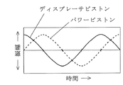
- FIG. 1 is a schematic configuration diagram of a free piston Stirling engine according to an embodiment of the present invention. It is a figure which shows the phase difference of a power piston and a displacer piston.
- a free piston Stirling engine 10 (hereinafter simply referred to as a Stirling engine) 10 according to the present embodiment includes a power piston 11, a displacer piston 12, a phase reversing mechanism 13, and a phase adjustment spring 14. ing.
- the power piston 11 reciprocates in the power cylinder 15 and is disposed in a pair facing the power cylinder 15.
- the pair of power pistons 11 are set to have the same mass and shape.
- the pair of power pistons 11 are disposed in the power cylinder 15 so as to reciprocate on the same axis La.
- the end of the power piston 11 on the side of the generator 30 described later is formed in a truncated cone shape.
- the displacer pistons 12 are respectively disposed in a pair of displacer cylinders 16 that are disposed to face each other with the intermediate portion of the power cylinder 15 interposed therebetween.
- the pair of displacer pistons 12 is set to have the same mass and shape.
- the pair of displacer pistons 12 are disposed in each displacer cylinder 16 so as to reciprocate on the same axis Lb and to reciprocate in a direction perpendicular to the reciprocating direction of the power piston 11. That is, each displacer cylinder 16 is arranged so that its longitudinal direction is orthogonal to the longitudinal direction of the power cylinder 15.
- the displacer piston 12 has a rod 17 provided at an end portion on the compression space 23 side, which will be described later, and this rod 17 is supported by a guide 18 provided in the displacer cylinder 16 so that the power cylinder is provided from the inside of the compression space 23. 15 is extended.
- the end of the displacer piston 12 on the side of the expansion space 22 described later is formed in a hemispherical shape.
- Each displacer cylinder 16 includes a heating unit (heater) 19 provided at one end, a cooling unit (cooler) 20 provided at the other end, and a stack (regenerator) provided between the heating unit 19 and the cooling unit 20. 21).
- the inside of each displacer cylinder 16 is partitioned by the displacer piston 12 into an expansion space 22 on the heating unit 19 side and a compression space 23 on the cooling unit 20 side.
- the expansion space 22 and the compression space 23 are divided into the heating unit 19, Communication is made through the stack 21 and the cooling unit 20.
- the compression space 23 of the displacer cylinder 16 is formed in a space in the power cylinder 15 (between the pair of power pistons 11 via a through hole 24 provided in the displacer cylinder 16 and a through hole 25 provided in the power cylinder 15. A space 26).
- the phase inversion mechanism 13 transmits the reciprocating motion of the displacer piston 12 to the power piston 11 with the phase inverted.
- the phase inversion mechanism 13 is a rhombus phase inversion link that connects a pair of power pistons 11 and includes four link members 13a having the same length.
- the phase inversion mechanism 13 is connected to the power piston 11 in a slit 27 provided at the end of the power piston 11 on the space 26 side in the power cylinder 15.
- the phase inversion mechanism 13 may connect the rods 17 of the pair of displacer pistons 12.
- the phase adjustment spring 14 is provided between the displacer piston 12 and the phase reversing mechanism 13 and adjusts the phase of the power piston 11 to be delayed by 90 degrees from the phase of the displacer piston 12 (see FIG. 2).
- the phase adjustment spring 14 is a leaf spring, one end of which is connected to the rod 17 of the displacer piston 12 and the other end is opposite to the rod 17 across the axis La of the power piston 11 in the phase inversion link. It is connected to the connecting point 28 on the side.
- the phase adjusting spring 14 is provided between the power piston 11 and the phase reversing mechanism 13.
- the generators 30 are disposed at both ends of the power cylinder 15 (upper and lower ends in the illustrated example).
- the generator 30 is a linear motion generator, and includes a stator 32 to which a coil 31 is attached, a mover 34 to which a permanent magnet 33 is attached, and both sides of the mover 34 in the reciprocating direction (in the illustrated example, up and down). And a spiral spring 35 sandwiched from the direction).
- a pair of power pistons 11 are arranged to face each other, and a pair of displacer pistons 12 are arranged to face each other. For this reason, while the vibrations accompanying the reciprocating motion of the power pistons 11 can be canceled by the power pistons 11, the vibrations accompanying the reciprocating motion of the displacer pistons 12 can be canceled by the displacer pistons 12, and the generation of vibrations can be suppressed. . Moreover, since the Stirling engine 10 according to the present embodiment includes the power piston 11 and the displacer piston 12 for two machines, the output of the Stirling engine 10 can be improved as compared with the conventional product in which the counterweight is arranged.
- the Stirling engine 10 it is possible to suppress the occurrence of vibration associated with the reciprocating motion of the power piston 11 and the displacer piston 12 without unnecessarily increasing the weight and volume of the Stirling engine 10 as a whole. Is possible.
- the Stirling engine 10 since the Stirling engine 10 according to the present embodiment includes the phase reversing mechanism 13 and the phase adjusting spring 14, the phase difference between the power piston 11 and the displacer piston 12 can be easily adjusted. This is because it is difficult to stably operate the Stirling engine 10 by adjusting the phase difference between the power piston 11 and the displacer piston 12 only with the gas spring in the space 26 in the power cylinder 15.
Landscapes
- Engineering & Computer Science (AREA)
- Chemical & Material Sciences (AREA)
- Combustion & Propulsion (AREA)
- Mechanical Engineering (AREA)
- General Engineering & Computer Science (AREA)
- Engine Equipment That Uses Special Cycles (AREA)
- Connection Of Motors, Electrical Generators, Mechanical Devices, And The Like (AREA)
Abstract
スターリングエンジン全体の重量、体積を無駄に増加させることなく、パワーピストン及びディスプレーサピストンの往復運動に伴う振動の発生を抑制する。 スターリングエンジン(10)は、パワーシリンダ(15)内に対向させて一対配置されたパワーピストン(11)と、パワーシリンダ(15)を挟んで対向させて配置された一対のディスプレーサシリンダ(16)内に各々配置されたディスプレーサピストン(12)と、を備える。
Description
本発明は、スターリングエンジンに関する。
フリーピストンスターリングエンジンは、一般的に、パワーシリンダ内を往復運動するパワーピストン(出力ピストン)と、ディスプレーサシリンダ内を往復運動するディスプレーサピストン(ディスプレーサ)とを備える。同スターリングエンジンは、ばねマス系の単振動を利用して作動する。このため、スターリングエンジン全体が大きく振動してしまうので、カウンターウエイトを配置して振動の発生を抑制している(例えば、特許文献1参照)。
カウンターウエイトを配置した従来品では、カウンターウエイトは少なくともパワーピストン及びディスプレーサピストンの質量と同程度の質量を必要とすると共に、カウンターウエイトを支持するばね等も必要となる。このため、スターリングエンジン全体の重量、体積が無駄に増加するという問題がある。
そこで、本発明の目的は、スターリングエンジン全体の重量、体積を無駄に増加させることなく、パワーピストン及びディスプレーサピストンの往復運動に伴う振動の発生を抑制することができるスターリングエンジンを提供することにある。
前述の目的を達成するために、本発明に係るスターリングエンジンは、パワーシリンダ内に対向させて一対配置されたパワーピストンと、前記パワーシリンダを挟んで対向させて配置された一対のディスプレーサシリンダ内に各々配置されたディスプレーサピストンと、を備えるものである。
前記スターリングエンジンは、前記ディスプレーサピストンの往復運動を前記パワーピストンに位相を反転させて伝達する位相反転機構と、前記ディスプレーサピストンと前記位相反転機構との間又は前記パワーピストンと前記位相反転機構との間に設けられ、前記パワーピストンの位相が前記ディスプレーサピストンの位相よりも90度遅れるように調整する位相調整ばねと、をさらに備えるものである。
本発明によれば、スターリングエンジン全体の重量、体積を無駄に増加させることなく、パワーピストン及びディスプレーサピストンの往復運動に伴う振動の発生を抑制することができるという優れた効果を奏する。
以下、本発明の好適な実施形態を添付図面に基づいて詳述する。
図1に示すように、本実施形態に係るフリーピストンスターリングエンジン(以下、単にスターリングエンジンという)10は、パワーピストン11と、ディスプレーサピストン12と、位相反転機構13と、位相調整ばね14とを備えている。
パワーピストン11は、パワーシリンダ15内を往復運動するものであり、パワーシリンダ15内に対向させて一対配置されている。これら一対のパワーピストン11は、互いに同じ質量、形状となるように設定されている。また、一対のパワーピストン11は、同一の軸線La上を往復運動するようにパワーシリンダ15内に配置されている。本実施形態では、パワーピストン11における後述する発電機30側の端部は、円錐台形に形成されている。
ディスプレーサピストン12は、パワーシリンダ15の中間部を挟んで対向させて配置された一対のディスプレーサシリンダ16内に各々配置されている。これら一対のディスプレーサピストン12は、互いに同じ質量、形状となるように設定されている。また、一対のディスプレーサピストン12は、同一の軸線Lb上を往復運動し、且つ、パワーピストン11の往復運動方向と直交する方向に往復運動するように各ディスプレーサシリンダ16内に配置されている。即ち、各ディスプレーサシリンダ16は、その長手方向がパワーシリンダ15の長手方向に対して直交するように配置されている。さらに、ディスプレーサピストン12は後述する圧縮空間23側の端部に設けられたロッド17を有し、このロッド17は、ディスプレーサシリンダ16に設けられたガイド18に支持され、圧縮空間23内からパワーシリンダ15内まで延出している。本実施形態では、ディスプレーサピストン12における後述する膨張空間22側の端部は、半球形に形成されている。
各ディスプレーサシリンダ16は、一端部に設けられる加熱部(ヒータ)19と、他端部に設けられる冷却部(クーラ)20と、加熱部19と冷却部20との間に設けられるスタック(再生器)21とを有する。各ディスプレーサシリンダ16の内部は、ディスプレーサピストン12により加熱部19側の膨張空間22と冷却部20側の圧縮空間23とに区画されており、膨張空間22と圧縮空間23とは、加熱部19、スタック21及び冷却部20を介して連通されている。さらに、ディスプレーサシリンダ16の圧縮空間23は、ディスプレーサシリンダ16に設けられた貫通孔24、及びパワーシリンダ15に設けられた貫通孔25を介して、パワーシリンダ15内の空間(一対のパワーピストン11間に区画される空間)26と連通されている。
位相反転機構13は、ディスプレーサピストン12の往復運動をパワーピストン11に位相を反転させて伝達するものである。本実施形態では、位相反転機構13は、一対のパワーピストン11同士を連結する菱形の位相反転リンクであり、互いに長さが等しい四つのリンク部材13aから構成されている。また、位相反転機構13は、パワーピストン11におけるパワーシリンダ15内の空間26側の端部に設けられたスリット27内においてパワーピストン11に連結されている。なお、位相反転機構13は、一対のディスプレーサピストン12のロッド17同士を連結するものであっても良い。
位相調整ばね14は、ディスプレーサピストン12と位相反転機構13との間に設けられ、パワーピストン11の位相がディスプレーサピストン12の位相よりも90度遅れるように調整するものである(図2参照)。本実施形態では、位相調整ばね14は、板ばねであり、一端がディスプレーサピストン12のロッド17に連結され、他端が位相反転リンクにおけるパワーピストン11の軸線Laを挟んで当該ロッド17とは反対側の連結点28に連結されている。なお、位相反転機構13が一対のディスプレーサピストン12のロッド17同士を連結するものである場合には、位相調整ばね14はパワーピストン11と位相反転機構13との間に設けられる。
また、本実施形態に係るスターリングエンジン10では、パワーシリンダ15の両端部(図示例では、上端部及び下端部)に各々、発電機30が配置されている。発電機30は、直動発電機であり、コイル31が装着された固定子32と、永久磁石33が装着された移動子34と、移動子34を往復運動方向の両側(図示例では、上下方向)から挟み込むスパイラルスプリング35とを有する。
次に、本実施形態に係るスターリングエンジン10による作用効果について説明する。
フリーピストンスターリングエンジンの基本的な動作原理は公知であるので、ここではパワーピストン11及びディスプレーサピストン12の動作のみについて説明する。
先ず、一対配置したディスプレーサピストン12の内の図1中右側のディスプレーサピストン12が左方に移動するときには、図1中左側のディスプレーサピストン12は右方に移動する。また、一対配置したパワーピストン11の内の図1中上側のパワーピストン11はディスプレーサピストン12に対して90度の位相遅れを持って下方に移動され、図1中下側のパワーピストン11はディスプレーサピストン12に対して90度の位相遅れを持って上方に移動される。
一方、一対配置したディスプレーサピストン12の内の図1中右側のディスプレーサピストン12が右方に移動するときには、図1中左側のディスプレーサピストン12は左方に移動する。また、一対配置したパワーピストン11の内の図1中上側のパワーピストン11はディスプレーサピストン12に対して90度の位相遅れを持って上方に移動され、図1中下側のパワーピストン11はディスプレーサピストン12に対して90度の位相遅れを持って下方に移動される。
本実施形態に係るスターリングエンジン10では、パワーピストン11同士を対向させて一対配置すると共に、ディスプレーサピストン12同士を対向させて一対配置している。このため、パワーピストン11同士によりパワーピストン11の往復運動に伴う振動を打ち消すと共に、ディスプレーサピストン12同士によりディスプレーサピストン12の往復運動に伴う振動を打ち消すことができ、振動の発生を抑制することができる。また、本実施形態に係るスターリングエンジン10は、二機分のパワーピストン11及びディスプレーサピストン12を備えるので、カウンターウエイトを配置した従来品と比較してスターリングエンジン10の出力を向上させることもできる。
一方、カウンターウエイトを配置した従来品では、カウンターウエイトに振動抑制の機能しかないため、スターリングエンジン全体の重量が単に増加し、且つ、スターリングエンジンの出力も向上しない。
即ち、本実施形態に係るスターリングエンジン10によれば、スターリングエンジン10全体の重量、体積を無駄に増加させることなく、パワーピストン11及びディスプレーサピストン12の往復運動に伴う振動の発生を抑制することが可能である。
さらに、本実施形態に係るスターリングエンジン10は位相反転機構13及び位相調整ばね14を備えるので、パワーピストン11とディスプレーサピストン12との位相差の調整が容易になる。パワーシリンダ15内の空間26のガスばねだけでは、パワーピストン11とディスプレーサピストン12との位相差を調整してスターリングエンジン10を安定作動させることは難しいためである。
以上、本発明の好適な実施形態について説明したが、本発明は前述の実施形態には限定されず他の様々な実施形態を採ることが可能である。
10 フリーピストンスターリングエンジン
11 パワーピストン
12 ディスプレーサピストン
13 位相反転機構
14 位相調整ばね
15 パワーシリンダ
16 ディスプレーサシリンダ
11 パワーピストン
12 ディスプレーサピストン
13 位相反転機構
14 位相調整ばね
15 パワーシリンダ
16 ディスプレーサシリンダ
Claims (2)
- パワーシリンダ内に対向させて一対配置されたパワーピストンと、
前記パワーシリンダを挟んで対向させて配置された一対のディスプレーサシリンダ内に各々配置されたディスプレーサピストンと、
を備えるスターリングエンジン。 - 前記ディスプレーサピストンの往復運動を前記パワーピストンに位相を反転させて伝達する位相反転機構と、
前記ディスプレーサピストンと前記位相反転機構との間又は前記パワーピストンと前記位相反転機構との間に設けられ、前記パワーピストンの位相が前記ディスプレーサピストンの位相よりも90度遅れるように調整する位相調整ばねと、
をさらに備える請求項1に記載のスターリングエンジン。
Applications Claiming Priority (2)
| Application Number | Priority Date | Filing Date | Title |
|---|---|---|---|
| JP2013116997A JP6194643B2 (ja) | 2013-06-03 | 2013-06-03 | フリーピストンスターリングエンジン |
| JP2013-116997 | 2013-06-03 |
Publications (1)
| Publication Number | Publication Date |
|---|---|
| WO2014196451A1 true WO2014196451A1 (ja) | 2014-12-11 |
Family
ID=52008097
Family Applications (1)
| Application Number | Title | Priority Date | Filing Date |
|---|---|---|---|
| PCT/JP2014/064299 Ceased WO2014196451A1 (ja) | 2013-06-03 | 2014-05-29 | スターリングエンジン |
Country Status (2)
| Country | Link |
|---|---|
| JP (1) | JP6194643B2 (ja) |
| WO (1) | WO2014196451A1 (ja) |
Citations (3)
| Publication number | Priority date | Publication date | Assignee | Title |
|---|---|---|---|---|
| JPS6365160A (ja) * | 1986-09-08 | 1988-03-23 | Aisin Seiki Co Ltd | スタ−リング機関のピストン駆動機構 |
| JPH04134173A (ja) * | 1990-09-26 | 1992-05-08 | Aisin Seiki Co Ltd | フリーピストンスターリングエンジン |
| JP2012533018A (ja) * | 2009-07-07 | 2012-12-20 | グローバル・クーリング・インク | ガンマ型フリー・ピストン・スターリング機関の構成 |
Family Cites Families (1)
| Publication number | Priority date | Publication date | Assignee | Title |
|---|---|---|---|---|
| JP3692506B2 (ja) * | 2001-04-25 | 2005-09-07 | 韶 松見 | 自由ピストン型再生スターリング機関 |
-
2013
- 2013-06-03 JP JP2013116997A patent/JP6194643B2/ja not_active Expired - Fee Related
-
2014
- 2014-05-29 WO PCT/JP2014/064299 patent/WO2014196451A1/ja not_active Ceased
Patent Citations (3)
| Publication number | Priority date | Publication date | Assignee | Title |
|---|---|---|---|---|
| JPS6365160A (ja) * | 1986-09-08 | 1988-03-23 | Aisin Seiki Co Ltd | スタ−リング機関のピストン駆動機構 |
| JPH04134173A (ja) * | 1990-09-26 | 1992-05-08 | Aisin Seiki Co Ltd | フリーピストンスターリングエンジン |
| JP2012533018A (ja) * | 2009-07-07 | 2012-12-20 | グローバル・クーリング・インク | ガンマ型フリー・ピストン・スターリング機関の構成 |
Also Published As
| Publication number | Publication date |
|---|---|
| JP2014234772A (ja) | 2014-12-15 |
| JP6194643B2 (ja) | 2017-09-13 |
Similar Documents
| Publication | Publication Date | Title |
|---|---|---|
| JP5995971B2 (ja) | 対向するピストンを備えるガンマ型形態のフリーピストン・スターリング機関 | |
| JP4542532B2 (ja) | 多段シリンダーからなるアルファ型フリーピストン・スターリング機関 | |
| CN102472166B (zh) | γ型自由活塞式斯特林机器的配置 | |
| TW201314041A (zh) | 線型壓縮機 | |
| CN104048436B (zh) | 一种线性整体式斯特林制冷机 | |
| JPS61207863A (ja) | 熱機関 | |
| JP5651947B2 (ja) | 熱音響機関 | |
| KR102527479B1 (ko) | 열-음향 히트 펌프 | |
| JP2009236456A (ja) | パルス管型蓄熱機関 | |
| JP5067260B2 (ja) | フリーピストン型のスターリングサイクル機械 | |
| JP6194643B2 (ja) | フリーピストンスターリングエンジン | |
| CN116498709A (zh) | 一种调谐曲轴惯容减振装置 | |
| JP6157394B2 (ja) | スターリング冷凍機 | |
| JP6153442B2 (ja) | スターリング型の冷凍機、及び膨張機 | |
| CN209875324U (zh) | 一种斯特林电机减震装置 | |
| JP5532938B2 (ja) | 熱音響機関 | |
| CN206503647U (zh) | 一种对置双头斯特林电机设备 | |
| CN107701652B (zh) | 一种串联扩展式惯性作动器及其作动方法 | |
| JP2006275352A (ja) | パルス管型蓄熱機関 | |
| US20040134733A1 (en) | Vibration absorber | |
| CN106968830A (zh) | 一种背向双头斯特林电机设备 | |
| CN206571592U (zh) | 一种背向双头斯特林电机设备 | |
| KR20150076747A (ko) | 선형 발전기 | |
| JP2004205088A (ja) | 蓄冷式冷凍機 | |
| JP5359580B2 (ja) | フリーピストン型スターリングエンジン |
Legal Events
| Date | Code | Title | Description |
|---|---|---|---|
| 121 | Ep: the epo has been informed by wipo that ep was designated in this application |
Ref document number: 14807266 Country of ref document: EP Kind code of ref document: A1 |
|
| NENP | Non-entry into the national phase |
Ref country code: DE |
|
| 122 | Ep: pct application non-entry in european phase |
Ref document number: 14807266 Country of ref document: EP Kind code of ref document: A1 |