WO2014192984A2 - Manufacturing method for packaged body of sanitary articles, and manufacturing device - Google Patents
Manufacturing method for packaged body of sanitary articles, and manufacturing device Download PDFInfo
- Publication number
- WO2014192984A2 WO2014192984A2 PCT/JP2014/073689 JP2014073689W WO2014192984A2 WO 2014192984 A2 WO2014192984 A2 WO 2014192984A2 JP 2014073689 W JP2014073689 W JP 2014073689W WO 2014192984 A2 WO2014192984 A2 WO 2014192984A2
- Authority
- WO
- WIPO (PCT)
- Prior art keywords
- packaging sheet
- label
- package
- continuous body
- line
- Prior art date
Links
Images


Classifications
-
- B—PERFORMING OPERATIONS; TRANSPORTING
- B65—CONVEYING; PACKING; STORING; HANDLING THIN OR FILAMENTARY MATERIAL
- B65B—MACHINES, APPARATUS OR DEVICES FOR, OR METHODS OF, PACKAGING ARTICLES OR MATERIALS; UNPACKING
- B65B9/00—Enclosing successive articles, or quantities of material, e.g. liquids or semiliquids, in flat, folded, or tubular webs of flexible sheet material; Subdividing filled flexible tubes to form packages
- B65B9/06—Enclosing successive articles, or quantities of material, in a longitudinally-folded web, or in a web folded into a tube about the articles or quantities of material placed upon it
- B65B9/067—Enclosing successive articles, or quantities of material, in a longitudinally-folded web, or in a web folded into a tube about the articles or quantities of material placed upon it the web advancing continuously
-
- B—PERFORMING OPERATIONS; TRANSPORTING
- B65—CONVEYING; PACKING; STORING; HANDLING THIN OR FILAMENTARY MATERIAL
- B65B—MACHINES, APPARATUS OR DEVICES FOR, OR METHODS OF, PACKAGING ARTICLES OR MATERIALS; UNPACKING
- B65B57/00—Automatic control, checking, warning, or safety devices
- B65B57/02—Automatic control, checking, warning, or safety devices responsive to absence, presence, abnormal feed, or misplacement of binding or wrapping material, containers, or packages
-
- B—PERFORMING OPERATIONS; TRANSPORTING
- B65—CONVEYING; PACKING; STORING; HANDLING THIN OR FILAMENTARY MATERIAL
- B65B—MACHINES, APPARATUS OR DEVICES FOR, OR METHODS OF, PACKAGING ARTICLES OR MATERIALS; UNPACKING
- B65B61/00—Auxiliary devices, not otherwise provided for, for operating on sheets, blanks, webs, binding material, containers or packages
- B65B61/02—Auxiliary devices, not otherwise provided for, for operating on sheets, blanks, webs, binding material, containers or packages for perforating, scoring, slitting, or applying code or date marks on material prior to packaging
-
- B—PERFORMING OPERATIONS; TRANSPORTING
- B65—CONVEYING; PACKING; STORING; HANDLING THIN OR FILAMENTARY MATERIAL
- B65B—MACHINES, APPARATUS OR DEVICES FOR, OR METHODS OF, PACKAGING ARTICLES OR MATERIALS; UNPACKING
- B65B61/00—Auxiliary devices, not otherwise provided for, for operating on sheets, blanks, webs, binding material, containers or packages
- B65B61/18—Auxiliary devices, not otherwise provided for, for operating on sheets, blanks, webs, binding material, containers or packages for making package-opening or unpacking elements
- B65B61/184—Auxiliary devices, not otherwise provided for, for operating on sheets, blanks, webs, binding material, containers or packages for making package-opening or unpacking elements by applying tabs over discharge openings, e.g. over discharge openings defined by tear or score lines
-
- B—PERFORMING OPERATIONS; TRANSPORTING
- B65—CONVEYING; PACKING; STORING; HANDLING THIN OR FILAMENTARY MATERIAL
- B65D—CONTAINERS FOR STORAGE OR TRANSPORT OF ARTICLES OR MATERIALS, e.g. BAGS, BARRELS, BOTTLES, BOXES, CANS, CARTONS, CRATES, DRUMS, JARS, TANKS, HOPPERS, FORWARDING CONTAINERS; ACCESSORIES, CLOSURES, OR FITTINGS THEREFOR; PACKAGING ELEMENTS; PACKAGES
- B65D75/00—Packages comprising articles or materials partially or wholly enclosed in strips, sheets, blanks, tubes, or webs of flexible sheet material, e.g. in folded wrappers
- B65D75/52—Details
- B65D75/58—Opening or contents-removing devices added or incorporated during package manufacture
- B65D75/5827—Tear-lines provided in a wall portion
- B65D75/5833—Tear-lines provided in a wall portion for tearing out a portion of the wall
- B65D75/5838—Tear-lines provided in a wall portion for tearing out a portion of the wall combined with separate fixed tearing means, e.g. tabs
Definitions
- the present invention relates to a method and apparatus for manufacturing a package of sanitary articles such as pocket-type wet tissue.
- sanitary articles such as pocket-type wet tissues and panty liners are provided to the market in the form of a package packaged in a single packaging sheet. And this hygiene article is taken out from a packaging sheet, for example one by one, and used.
- Patent Document 1 discloses a technique in which an openable / closable lid is formed after opening a packaging sheet as an example of such a package.
- packaging sheet 27 disclosed in Patent Document 1 will be schematically described with reference to FIGS. 2A, 2B, and 4 described later.
- the packaging sheet 27 is first formed with perforations 27M so as to substantially surround the predetermined portion 27cap, and a label 28 is joined to the portion corresponding to the perforations 27M.
- the packaging sheet 27 is opened by cutting the perforation 27M by picking up the label 28 and pulling it up. That is, as shown in FIG. 4, the predetermined portion 27cap is generally separated from the packaging sheet 27, and the packaging sheet 27 is formed with an outlet 27h having a shape corresponding to the predetermined portion 27cap.
- the predetermined portion 27cap is not completely separated from the packaging sheet 27, that is, is connected to the packaging sheet 27 via the unformed portion 27Mb of the perforation 27M. Therefore, the predetermined portion 27cap is an open / close lid 27cap that can be opened and closed with the unformed portion 27Mb as a hinge. Further, the label 28 is bonded to the predetermined portion 27cap, which mainly becomes the opening / closing lid 27cap, of the packaging sheet 27 with an adhesive, whereby the opened label 28 is opened / closed integrally with the opening / closing lid 27cap.
- the label 28 protrudes from the tip portion 27Mt of the opening / closing lid 27cap, and can be rejoined to the portion 27ha around the take-out port 27h of the packaging sheet 27 by the adhesive of the protruding portion 28p. It has become.
- the user of the package 21 takes out a hygienic article such as wet tissue from the take-out port 27h of the package sheet 27, the user can fix the take-out port 27h in the closed state with the open / close lid 27cap. .
- the sanitary article can be put into a bag while being kept clean.
- the sanitary article G11 is transported at a predetermined transport pitch PG11 along the transport direction (MD direction) by the transport device 32 such as a conveyor. Note that a space is provided between the sanitary articles G11 and G11 adjacent in the transport direction based on the predetermined pitch PG11.
- another transporting device 34 transports the continuous body 27a of the packaging sheet 27 continuous in the transporting direction, and the perforation forming device 40 and the labeler device 50 are located at predetermined positions in the transporting direction. Arranged in order. Therefore, when passing through the perforation forming device 40, the perforation 27M is formed in the portion corresponding to the sanitary article G11 in the continuous body 27a, and when passing through the labeler device 50, the continuous A label 28 is bonded to the body 27a for each perforation 27M.
- the continuous body 27a of the packaging sheet 27 is joined to the transport device 32 that transports the sanitary article G11.
- the continuous body 27a passes through the bending guide member 70.
- the end portions 27aew and 27aew in the width direction (CD direction) intersecting the transport direction in the continuous body 27a of the packaging sheet 27 are bent, respectively, so that the continuous body 27a is formed into a cylindrical shape.
- the continuum 27a is encased in the sanitary article G11.
- the sealing device 80 seals the continuum 27a of the packaging sheet 27 in a state of wrapping the sanitary article G11. 27s of sealing parts are formed in the part between hygiene articles G11 and G11 among 27a.
- the said cutter apparatus 90 cut disconnects the continuous body 27a of the packaging sheet 27 by making the position contained in the sealing part 27s into the cutting position Pc, and has the above.
- a package 21 formed by packaging the article G11 is generated.
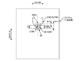
- the formation position in the transport direction of the portion 27Mt of the perforation 27M that becomes the tip of the opening / closing lid 27cap is, for example, 30 mm ⁇ 10 mm from the cutting position Pc.
- the joining position of the downstream end portion 28ed in the conveyance direction of the label 28 is managed so as to fall within a range of, for example, 23 mm ⁇ 5 mm from the cutting position Pc. That is, both positions are managed based on the cutting position Pc. Along with this, those out of these ranges are rejected, that is, rejected and discarded.
- the function of the label 28 is that the perforation 27M is surely cut and opened by pinching and lifting at the time of opening, and the opening / closing lid 27cap is closed by the adhesive of the label 28 after opening.
- it is determined that the one that performs the function of the label 28 as described above is acceptable when the determination is made based on the formation position of the perforation 27M for the determination of pass / fail of the bonding position of the label 28. In other words, it is considered that it is possible to appropriately determine whether or not the joining position of the label 28 is acceptable.
- the present invention has been made in view of the above-described conventional problems, and its purpose is to provide a hygienic package sheet in which an opening / closing lid is formed after opening by being cut along a weak line such as a perforation.
- a weak line such as a perforation.
- the main invention for achieving the above object is: A method for producing a package in which at least one sanitary article is packaged by a packaging sheet,
- the packaging sheet that packages the sanitary article has a portion that becomes an opening / closing lid after opening by being cut along the line of weakness when opened, and a portion corresponding to the line of weakness in the packaging sheet is opened
- a label that sometimes becomes a knob is joined so that it can be fixed with the opening and closing lid closed after opening
- the manufacturing method includes: Transporting a plurality of the sanitary articles along a transport direction, transporting the sanitary articles adjacent to each other in the transport direction with a gap therebetween; Forming the line of weakness in a portion corresponding to the sanitary article in a continuous body of the packaging sheet continuous in the transport direction; Bonding the label for each line of weakness to the continuum of the packaging sheet; Determining pass / fail of the bonding position of the label in the packaging sheet based on the relative positional relationship between the weak line and the label in the continuum of the packaging sheet; Wrapping
- An apparatus for manufacturing a package in which at least one sanitary article is packaged by a packaging sheet The packaging sheet that packages the sanitary article has a portion that becomes an opening / closing lid after opening by being cut along the line of weakness when opened, and a portion corresponding to the line of weakness in the packaging sheet is opened A label that sometimes becomes a knob is joined so that it can be fixed with the opening and closing lid closed after opening,
- the manufacturing apparatus includes: An apparatus for conveying a plurality of the hygiene articles along a conveying direction, wherein the apparatus conveys the sanitary articles adjacent to each other in the conveying direction with a gap therebetween; An apparatus for forming the line of weakness in a portion corresponding to the sanitary article in the continuous body of the packaging sheet that is continuous in the transport direction; An apparatus for joining the label for each line of weakness with respect to the continuous body of the packaging sheet; An apparatus for determining pass / fail of the bonding position of the label in the packaging sheet, based on the relative positional relationship between the weak line and the label in the continuum of the packaging
- FIG. 1A is a schematic plan view of the panty liner 1
- FIG. 1B is a cross-sectional view taken along the line BB in FIG. 1A
- FIG. 1C is a schematic plan view of the individual package 11 of the panty liner 1
- 1D is a schematic plan view of a state in which the individual package 11 of the panty liner 1 of FIG. 1C is unwrapped.
- 2A is a schematic perspective view of a package 21 formed by further packaging individual packages 11, 11,...
- FIG. 2B is a schematic plan view of the package 21, and FIG. It is C sectional drawing.
- 3A is a schematic plan view of the packaging sheet 27 before packaging, and FIG.
- 3B is a schematic plan view of a state in which the individual packaging product group G11 is wrapped by forming the packaging sheet 27 into a cylindrical shape.
- These are the schematic plan views of the package 21 of the individually packaged product group G11 formed by sealing the openings 27ek and 27ek at both ends in the cylinder axis direction C27 of the cylindrical packaging sheet 27 by welding or the like.
- It is a schematic perspective view of the package body 21 opened by the perforation 27M.
- 5A is a schematic side view of the production line 30 of the package body 21, FIG. 5B is a view taken along the line BB in FIG. 5A, and FIG. 5C is a view taken along the line CC in FIG. 5A. is there.
- FIG. 3 is a schematic side view of a perforation forming device 40.
- FIG. 2 is a schematic side view of a labeler device 50.
- FIG. 2 is a schematic side view of an inspection device 60.
- FIG. It is an image figure of the plane image which plane image data shows.
- FIG. 10A is a binarized image of the perforation, and
- FIG. 10B is a binarized image of the label 28.
- a method for producing a package in which at least one sanitary article is packaged by a packaging sheet The packaging sheet that packages the sanitary article has a portion that becomes an opening / closing lid after opening by being cut along the line of weakness when opened, and a portion corresponding to the line of weakness in the packaging sheet is opened
- a label that sometimes becomes a knob is joined so that it can be fixed with the opening and closing lid closed after opening
- the manufacturing method includes: Transporting a plurality of the sanitary articles along a transport direction, transporting the sanitary articles adjacent to each other in the transport direction with a gap therebetween; Forming the line of weakness in a portion corresponding to the sanitary article in a continuous body of the packaging sheet continuous in the transport direction; Bonding the label for each line of weakness to the continuum of the packaging sheet; Determining pass / fail of the bonding position of the label in the packaging sheet based on the relative positional relationship between the weak line and the label in the continuum of the packaging sheet; Wrapping the sanitary article in the continuum of the packaging sheet by
- the determination of pass / fail is performed based on image data generated by imaging the weak line and the label in the continuum of the packaging sheet. Therefore, the pass / fail determination can be performed accurately.
- a method of manufacturing a package for such a hygiene article The imaging is preferably performed before the wrapping.
- a continuum of packaging sheets is imaged before wrapping, and the image data captured at such timing is in a state in which the continuum of packaging sheets is substantially flat.
- the relative positional relationship between the line of weakness and the label is shown. Therefore, this relative positional relationship is extremely accurate. And since the determination of the pass / fail of the bonding position of the label is performed based on the relative positional relationship shown correctly, the determination accuracy of the pass / fail can be improved.
- the continuous body of the packaging sheet has, as three directions orthogonal to each other, a continuous direction in which the continuous body continues, a thickness direction, and a width direction,
- the packaging sheet is a sheet through which the other side can be seen through from one side in the thickness direction,
- the imaging is performed by a camera, and the camera images the surface of the one side of the continuous body of the packaging sheet, It is desirable that a light-shielding member having a non-ground surface is provided so as to face the other surface, which is the surface opposite to the one surface captured by the camera.
- the image of the image data obtained by imaging one side of the continuum of packaging sheets with a camera includes a continuum of packaging sheets.
- an irrelevant member positioned on the other side in the thickness direction may be reflected, and this reflection causes an erroneous determination in the above pass / fail determination.
- a light shielding member having a non-ground surface is provided so as to face the other surface which is the opposite surface of the one surface of the continuum of the packaging sheet,
- a non-ground prevents reflection of a member located on the other side of the light shielding member. Therefore, it is possible to prevent a decrease in accuracy of pass / fail judgment that can occur when a continuous body of packaging sheets that can be seen through is used.
- a method of manufacturing a package for such a hygiene article In determining pass / fail, based on the image data, a value corresponding to the size of the interval between the predetermined portion of the weak line and the predetermined portion of the label is used as information indicating the relative positional relationship. Calculate When the calculated value is included in a predetermined allowable range, it is desirable to determine that the value is acceptable.
- a value corresponding to the size of the gap between the predetermined portion of the weak line and the predetermined portion of the label is used as information indicating the relative positional relationship. Make a decision. Therefore, this determination can be performed accurately and reliably.
- a method of manufacturing a package for such a hygiene article It has a target value related to the interval in advance, Obtaining a difference between the calculated value and the target value; It is desirable to change at least one of the formation position of the weak line and the joining position of the label in the transport direction so that the obtained difference is reduced.
- At least one of the position where the weak line is formed and the position where the label is joined is changed in the transport direction so that the above-described difference is reduced. Therefore, it can adjust reliably in the direction in which the determination of the pass / fail of the bonding position of the label is acceptable.
- a method of manufacturing a package for such a hygiene article In determining the pass / fail, When generating the first binarized image by binarizing the image data based on the first threshold value, the first binarized image is specified by one of the two values. Binarization processing is performed so that the image includes the imaging portion of the weak line on the image indicated by the image data, When the image data is binarized based on a second threshold to generate a second binarized image, the second binarized image is specified by one of the binaries.
- Binarization processing is performed so that the image includes the imaging portion of the label on the image indicated by the image data, Based on both the position of the imaging portion of the weak line in the first binarized image and the position of the imaging portion of the label in the second binarized image, the weak line and the label It is desirable to generate information indicating the relative positional relationship.
- a first binarized image specialized in specifying the position of the imaging portion of the weak line is generated based on the first threshold, and the second Based on the threshold value, a second binarized image specialized for specifying the position of the imaging portion of the label is generated.
- the information which shows the relative positional relationship of a weak line and a label is produced
- a method of manufacturing a package for such a hygiene article The line of weakness is not set in the portion that becomes the hinge of the opening / closing lid in the continuous body of the packaging sheet,
- the fragile line is formed such that a portion of the fragile line that becomes the tip of the opening / closing lid is located on one side in the transport direction from the part that becomes the hinge,
- the label is joined to the continuum of the packaging sheet so that the label covers the portion that becomes the tip of the weakened line, It is preferable that the pass / fail judgment is made based on a relative positional relationship between a portion of the weakened line that becomes the tip of the opening / closing lid and the label.
- the label is joined across the portion of the weak line that becomes the tip of the opening / closing lid in the transport direction, whereby the label is pinched at the time of opening.
- it functions as a fixing member that fixes the opening / closing lid in a closed state after opening. Therefore, the part which becomes the front-end
- cover is an important part in the meaning that the said function is exhibited reliably.
- the portion that becomes the tip of the opening / closing lid in the weak line is the target of attention in the relative positional relationship, and thereby the portion that becomes the tip of the opening / closing lid and the label
- the relative positional relationship of can be calculated accurately. Therefore, what a label performs said function can be determined to be a pass.
- a method of manufacturing a package for such a hygiene article The line of weakness is not set in the portion that becomes the hinge of the opening / closing lid in the continuous body of the packaging sheet,
- the fragile line is formed such that a portion of the fragile line that becomes the tip of the opening / closing lid is located on one side in the transport direction from the part that becomes the hinge,
- the label is joined to the continuous body of the packaging sheet so that the label crosses the portion that becomes the tip of the line of weakness in the transport direction,
- the label has a design, In the determination, it is preferable to determine that the pass is passed when a predetermined portion of the weak line overlaps the symbol.
- the total light transmittance of the packaging sheet is preferably 60% or more.
- the total light transmittance of the packaging sheet is 60% or more. Therefore, the sanitary article inside the package can be easily visually recognized from the outside of the package. As a result, the design and the like drawn on the sanitary article can be shown as if they were the design of the package, and the degree of freedom in design of the package can be increased.
- the sanitary article is an individual packaged product in which absorbent articles are individually packaged,
- In the transport a plurality of the individually packaged products are transported in the transport direction in a stacked state,
- In the wrapping it is desirable to wrap the plurality of the individually packaged products in the stacked state with a continuous body of the packaging sheets.
- An apparatus for manufacturing a package in which at least one sanitary article is packaged by a packaging sheet The packaging sheet that packages the sanitary article has a portion that becomes an opening / closing lid after opening by being cut along the line of weakness when opened, and a portion corresponding to the line of weakness in the packaging sheet is opened A label that sometimes becomes a knob is joined so that it can be fixed with the opening and closing lid closed after opening,
- the manufacturing apparatus includes: An apparatus for conveying a plurality of the hygiene articles along a conveying direction, wherein the apparatus conveys the sanitary articles adjacent to each other in the conveying direction with a gap therebetween; An apparatus for forming the line of weakness in a portion corresponding to the sanitary article in the continuous body of the packaging sheet that is continuous in the transport direction; An apparatus for joining the label for each line of weakness with respect to the continuous body of the packaging sheet; An apparatus for determining pass / fail of the bonding position of the label in the packaging sheet, based on the relative positional relationship between the weak line and the label in the continuum of the packaging
- the determination of pass / fail of the label joining position is performed based on the relative positional relationship between the weak line and the label. Therefore, it is possible to appropriately determine whether the label joining position is acceptable.
- the determination of pass / fail is performed based on image data generated by imaging the weak line and the label in the continuum of the packaging sheet. Therefore, the pass / fail determination can be performed accurately.
- the manufacturing method and the manufacturing apparatus 30 of this embodiment manufacture the packaging body 21 of sanitary goods.
- the hygiene article is an individual package 11 in which the panty liner 1 as an example of an absorbent article is individually packaged, and the package 21 of the hygiene article includes the individual packages 11, 11,.
- a plurality of stacked sheets are packaged by the packaging sheet 27.
- FIG. 1A is a schematic plan view of the panty liner 1
- FIG. 1B is a cross-sectional view taken along the line BB in FIG. 1A
- FIG. 1C is a schematic plan view of the individual packaged article 11 of the panty liner 1
- FIG. 1D is a state where the individual packaged article 11 of the panty liner 1 of FIG. 1C is unpacked, that is, the individual packaging sheet 7 and the panty liner. It is a schematic plan view of the unfolding state which opened both of 1 together.
- a panty liner 1 includes an absorbent body 2 formed by laminating liquid absorbent materials such as pulp fibers in a predetermined shape, and a liquid permeable top sheet 3 from both sides in the thickness direction. It is a thin sheet-like member covered with a liquid-impermeable back sheet 4 and its planar shape is, for example, a substantially hourglass shape.
- a non-slipping adhesive 5 used for fixing to the undergarment is applied to the surface of the back sheet 4 that forms the non-skin side surface of the liner 1.
- a release sheet 6 is provided so as to cover the slip-off preventing adhesive 5.
- the release sheet 6 is firmly joined to an individual packaging sheet 7 to be described later, and when the liner 1 is used, the release sheet 6 is separated from the adhesive 5 for preventing the liner 1 together with the individual packaging sheet 7. It is peeled off quickly.
- the individual packaging sheet 7 provided for individual packaging of the liner 1 is, for example, a rectangular sheet in plan view. And in the state which piled up the panty liner 1 on the packaging sheet 7, the planar size of the sheet 7 is made into the planar size which protrudes outward from at least three sides of the four sides of the panty liner 1. .
- the individual packaging sheet 7 protrudes on both sides in the width direction of the panty liner 1 and on one side in the longitudinal direction, but on the other side in the longitudinal direction, Is popping out of the individual packaging sheet 7.
- the individual packaging sheet 7 three fold lines of a first fold line, a second fold line, and a third fold line as an example of a plurality of fold lines are set at different positions in the longitudinal direction. . Then, the individual wrapping sheet 7 together with the liner 1 is folded three times in the longitudinal direction in the order close to the portion where the liner 1 protrudes, that is, in the order of the first, second and third fold lines. In the state, a joining portion 7s such as a seal portion is provided at a predetermined portion or the like that forms an outer contour. And the individual packaging sheet 7 is sealed in such a state that the liner 1 is accommodated by the joining portion 7s, thereby forming the individual packaging product 11 of FIG. 1C.
- a joining portion 7s such as a seal portion is provided at a predetermined portion or the like that forms an outer contour.
- this individual package 11 is a vertically long member with the dimension L11 of the direction orthogonal to the folded direction longer than the dimension W11 of the folded direction.
- the direction of the long dimension L11 is referred to as “longitudinal direction”
- the direction of the short dimension W11 is referred to as “width direction”.
- the direction orthogonal to both the longitudinal direction and the width direction is the thickness direction of the individually packaged product 11.
- FIG. 2A to FIG. 2C are explanatory diagrams of a package 21 formed by further packaging such individual packages 11, 11.
- 2A is a schematic perspective view of the package body 21
- FIG. 2B is a schematic plan view of the package body 21
- FIG. 2C is a cross-sectional view taken along the line CC in FIG. 2B.
- the package body 21 includes an individual package product group G11 in which six individual package products 11, 11,... Are stacked in the thickness direction, and a packaging sheet 27 that packages the individual package product group G11.
- a colorless and transparent resin film is used as the packaging sheet 27, so that the individual individual packaged products 11, 11... Can be seen from the outside of the package 21. If the total light transmittance of the packaging sheet 27 (see JIS K 7105 measurement method A) is 60% or more, the individual packaged items 11, 11. Accordingly, the design of each individual package 11 can be seen as if it is the design of the package 21, which is preferable.
- the packaging sheet 27 is not limited to a colorless and transparent resin film.
- the packaging sheet 27 may be colored, translucent, opaque, non-woven fabric, woven fabric, or a material other than resin.
- the packaging sheet 27 before packaging is, for example, a rectangular sheet, and its planar size is larger than the planar size of the individual packaged product group G11.
- the packaging body 21 of FIG. 2A is formed when this packaging sheet 27 packages the individual packaged goods group G11 as follows. First, in a state where the individual packaged product group G11 is placed at the approximate center of the plane of the packaging sheet 27 in FIG. 3A, the respective portions 27ew and 27ew of the packaging sheet 27 projecting sideways from both sides in the width direction of the individual packaged product 11 are shown. As shown in FIG. 3B, the portions 27ew and 27ew are overlapped with each other above the individually packaged product group G11 to form the packaging sheet 27 in a cylindrical shape.
- the packaging sheets 27 are fixed in a cylindrical shape by joining the parts 27ew and 27ew with an adhesive, thereby fixing the individual packaged product group G11 in a state of being wrapped by the packaging sheet 27. And as shown to FIG. 3B and FIG. 3C, each opening part 27ek and 27ek of the both ends of the cylinder axial direction C27 of this cylindrical packaging sheet 27 are sealed by welding etc., respectively, and sealing part 27s and 27s are formed. Thus, the package 21 of the individually packaged product group G11 is formed.
- the package 21 has a substantially rectangular parallelepiped shape. And the longitudinal direction of the package body 21 faces the same direction as the longitudinal direction of the individual package products 11, 11..., And the width direction of the package body 21 is the same as the width direction of the individual package products 11, 11. Similarly, the thickness direction of the package 21 is the same as the thickness direction of the individually packaged items 11, 11.
- the outer shape of the packaging sheet 27 in the packaged state as shown in FIG. 2A also has a substantially rectangular parallelepiped shape, that is, the longitudinal direction and the width.
- a pair of plane portions 27A1, 27A1 generally defined by the direction
- a pair of side surface portions 27A2, 27A2 generally defined by the longitudinal direction and the thickness direction
- the pair of end surface portions 27A3 and 27A3 are provided with the sealing portions 27s and 27s, respectively.
- attached with the adhesive agent belong to the plane part 27A1 of the side which cannot be seen.
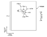
- a perforation 27M (corresponding to a fragile line) is formed on the flat portion 27A1 of the packaging sheet 27 for opening the packaging sheet 27.
- the perforation 27M is formed in a substantially chevron shape so as to substantially surround the predetermined portion 27cap in the plane portion 27A1.
- the bottom portion 27Mb in the substantially chevron shape is located on the end side in the longitudinal direction of the flat surface portion 27A1, and the top portion 27Mt in the substantially chevron shape (corresponding to “the portion that becomes the front end portion of the opening / closing lid”) is the central side in the longitudinal direction. Is located.
- the perforation 27M is substantially not formed in the portion corresponding to the bottom portion 27Mb in the flat portion 27A1. Further, a rectangular label 28 is joined by an adhesive (not shown) so as to cover the substantially mountain-shaped top portion 27Mt of the perforation 27M.
- the packaging sheet 27 is opened as follows. First, as shown in FIGS. 2A and 2B, the portion 28 p of the perforation 27 ⁇ / b> M that protrudes from the top portion 27 ⁇ / b> Mt to the center side in the longitudinal direction is pinched and pulled away from the packaging sheet 27. Then, the perforation 27M is gradually cut from the apex 27Mt as a starting point, and the cutting range is expanded to the end side in the longitudinal direction. And finally, as shown in FIG. 4, it reaches the bottom portion 27Mb having a substantially chevron shape, but since the perforation 27M is not formed in the bottom portion 27Mb, the cutting stops at the bottom portion 27Mb.
- the predetermined portion 27cap surrounded by the substantially chevron-shaped perforations 27M is separated from the packaging sheet 27 except for the portion corresponding to the bottom portion 27Mb, and the packaging sheet 27 corresponds to the predetermined portion 27cap.
- a substantially chevron shaped outlet 27h is formed.
- the predetermined portion 27cap is an open / close lid 27cap that can be opened and closed with the bottom 27Mb as a hinge.
- the label 28 is mainly bonded to the predetermined portion 27cap of the packaging sheet 27 with an adhesive, whereby the label 28 also opens and closes integrally with the opening / closing lid 27cap after opening.
- the part 28p of the label 28 protrudes outward from the opening / closing lid 27cap, and can be rejoined to the portion 27ha around the take-out port 27h of the packaging sheet 27 by the adhesive of the protruding portion 28p. It has become.
- the user of the packaging body 21 takes out the individual packaged product 11 from the packaging sheet 27, the user can fix the takeout opening 27h closed with the open / close lid 27cap any number of times.
- the individual packaged items 11, 11 can be carried around, for example, in a bag while maintaining good hygiene.
- FIG. 5A is a schematic side view of the production line 30.
- 5B is a BB arrow view in FIG. 5A
- FIG. 5C is a CC arrow view in FIG. 5A.
- 5B and 5C are diagrams mainly illustrating a state in which the continuous body 27a of the packaging sheet 27, the individual packaged product group G11, and the like gradually change to the package body 21, and therefore FIG. And in FIG. 5C, each apparatus 40, 50, 60, 70 of the production line 30 is not illustrated.
- the production line 30 includes a transport device 32 such as a belt conveyor or a transport roller, as shown in FIGS. 5A and 5C.
- the transport device 32 transports the individual packaged product group G11 in which the six individual packaged products 11, 11... Are stacked in the thickness direction at a predetermined transport pitch PG11 along the transport direction.
- the conveyance direction is referred to as “MD direction”, and the direction orthogonal to the MD direction is referred to as “CD direction”.
- the width direction of the individual package product 11 is along the CD direction, and thereby the individual package product group G11 is conveyed in a state in which the longitudinal direction of each individual package product 11 is along the MD direction.
- the CD direction corresponds to the “crossing direction intersecting the transport direction” according to the claims.
- a continuous body 27 a of a packaging sheet 27 continuous in the MD direction is transported in the MD direction.
- the perforation forming device 40 and the labeler device 50 are arranged in this order from the upstream in the MD direction to the downstream at a predetermined position in the MD direction. Therefore, when passing through the perforation forming device 40, a substantially chevron-shaped perforation 27M is formed in a portion corresponding to the individually packaged product group G11 in the continuous body 27a, and the labeler device 50 is When passing, a rectangular label 28 is bonded to the continuous body 27a for each substantially mountain-shaped perforation 27M.
- an inspection device 60 is arranged at a downstream position in the MD direction of the labeler device 50.
- the inspection device 60 inspects the joining position of the label 28 in the continuous body 27 a of the packaging sheet 27.
- the inspection result is displayed on a display unit (not shown) such as a monitor to notify the operator.
- the continuous body 27a of the packaging sheet 27 that has passed through the inspection device 60 joins the transport device 32 that transports the individually packaged product groups G11, G11,. And the continuous body 27a of the packaging sheet 27 which merged with the conveyance apparatus 32 in the confluence
- G11, G11... Are substantially integrated and conveyed along the MD direction. And it passes the bending guide member 70 arrange
- the end portions 27 aew and 27 aew in the CD direction of the continuous body 27 a of the packaging sheet 27 are bent.
- the continuous body 27a of the packaging sheet 27 is formed into a cylindrical shape by overlapping the end portions 27aew and 27aew on the individual packaged product group G11, and the adhesive applied to the end portions 27aew and 27aew.
- the end portions 27 aew and 27 aew are joined to each other by the agent, and the continuous body 27 a is fixed in a cylindrical shape. And thereby, the continuous body 27a will be in the state which wrapped the individual packaged goods group G11.
- coating of said adhesive agent is made
- the continuous body 27a of the cylindrical packaging sheet 27 passes through the sealing device 80 downstream in the MD direction. And during the passage, the sealing device 80 seals the continuous body 27a of the cylindrical packaging sheet 27 that encloses the individual packaged goods group G11, and the individual packaged goods group in the continuous body 27a of the packaging sheet 27.
- a sealing portion 27s is formed in a portion between G11 and G11.
- FIG. 6 is a schematic side view of the perforation forming device 40.
- the perforation forming apparatus 40 has, for example, a pair of upper and lower rolls 41a and 41b. Each of the rolls 41a and 41b rotates around the rotation axes C41a and C41b along the CD direction, and thereby rotates so as to send the continuous body 27a of the packaging sheet 27 downstream in the MD direction.
- the rotation drive source is a servo motor.
- one roll 41a of the pair of upper and lower rolls 41a and 41b is a perforation blade roll 41a having a substantially chevron-shaped perforation blade 42 corresponding to the perforation 27M on the outer peripheral surface
- the other roll 41b is an anvil roll 41b which receives the perforation edge 42 with a smooth outer peripheral surface.
- the formation pitch P27M of the perforations 27M is substantially the same as the transport pitch PG11 of the individual packaged product group G11 described above, whereby the perforations 27M are formed corresponding to each individual packaged product group G11. .
- the realization of the formation pitch P27M and the conveyance pitch PG11 is achieved by aligning the arrangement pitch of the perforated blades 42 in the circumferential direction of the upper roll 41a to the same value as the conveyance pitch PG11. For example, in this example, since the total length of the rotation trajectory for one rotation of the perforation blade 42 is twice the conveyance pitch PG11, the perforation blade 42 is positioned at two positions in the circumferential direction of the perforation blade roll 41a. Are provided at equal pitches.
- each roll 41a, 41b is made to rotate substantially synchronizing with the conveyance speed value of the continuous body 27a of the packaging sheet 27, and, thereby, in the position of the perforation blade 42 of the perforation blade roll 41a.
- Both the peripheral speed value (m / second) and the peripheral speed value (m / second) of the outer peripheral surface of the anvil roll 41b are respectively the conveyance speed value (m / second) in the MD direction of the continuous body 27a of the packaging sheet 27. It is almost complete. Therefore, when the perforation blade 42 hits the continuous body 27a of the packaging sheet 27, the perforation 27M is smoothly formed on the continuous body 27a of the packaging sheet 27 by the perforation blade 42.
- Such synchronization is realized by position control of a servo motor (not shown) that drives each of the rolls 41a and 41b by an appropriate controller based on the synchronization signal, which will be described later.
- the substantially chevron shape of the perforation 27M is formed in a state facing the upstream side in the MD direction, and thereby the top portion 27Mt of the substantially chevron shape of the perforation 27M is It forms the upstream end in the MD direction of the perforation 27M.
- FIG. 7 is a schematic side view of the labeler device 50.
- the labeler device 50 is a device 50 that joins the label 28 to each perforation 27M formed in the continuous body 27a of the packaging sheet 27 (see FIG. 5B).
- the label 28 is carried in the form of a label paper roll R28L in which the label paper 28L is wound up in a roll shape.
- the label paper 28L is also called a so-called sticker paper, and has a long strip-shaped release paper 28S (also referred to as a separator), and a plurality of labels 28, 28... attached.
- the labels 28, 28... Are attached side by side at a predetermined attaching pitch P0 in the longitudinal direction of the strip-like release paper 28S. Then, the labeler device 50 peels the label 28 on the most downstream side in the feeding direction from the release paper 28S in order while feeding the label paper 28L, and joins it to the continuous body 27a of the packaging sheet 27.
- the labeler device 50 includes a reel 51 for feeding out the label paper 28L from the label paper roll R28L, and a take-up reel 52 for taking up the release paper 28S from which the label 28 has been peeled off.
- a mechanism 52 that peels the label 28 from the label paper 28L and joins it to the continuous body 27a of the packaging sheet 27 is provided at a predetermined position in the feeding path of the label paper 28L set between the reels 51 and 52. It has been.
- the mechanism 52 has a knife edge member 53 that is pointed in the feeding direction.
- the feeding path of the label paper 28L is generally reversed at the pointed tip 53e of the knife edge member 53.
- the label paper 28L passes through the position of the tip 53e of the knife edge member 53, only the release paper 28S is reversed, and the label 28 cannot be reversed and goes straight, so that the label 28 is released. It is peeled from 28S. Then, the peeled label 28 is sent between a pair of upper and lower pinch rolls 54a and 54b located immediately before, and between these pinch rolls 54a and 54b, a continuous body 27a of the packaging sheet 27 is also provided. It is conveyed along the MD direction. Therefore, the label 28 is overlapped and joined to the upper surface of the continuous body 27a of the packaging sheet 27 at the positions of the pinch rolls 54a and 54b.
- the sticking pitch P0 of the label 28 on the release paper 28S and the joining pitch P28 of the label 28 on the continuous body 27a of the packaging sheet 27 are not equal to each other,
- the joining pitch P28 is larger than the sticking pitch P0.
- the feeding speed value (m / second) of the feeding operation of the label paper 28L is set to the continuous body 27a of the packaging sheet 27. It is necessary to join at a value substantially equal to the conveyance speed value (m / sec). Therefore, the labeler device 50 joins the label 28 to the continuous body 27a of the packaging sheet 27 while intermittently feeding out the label paper 28L.
- the label 28 is joined to the continuous body 27a while feeding out the label paper 28L with the feeding speed value being substantially the same as the conveyance speed value of the continuous body 27a of the packaging sheet 27, and the joining pitch P28 is pasted.
- the inconsistency with the attached pitch P0 is dealt with by providing a feeding stop state between the feeding operations by an amount corresponding to the joining pitch P28 being longer than the pasting pitch P10.
- the feeding amount per one time of such intermittent feeding operation is preset to the same value as the above-mentioned sticking pitch P28. Further, the resumption of the feeding operation from the stopped state is performed based on the synchronization signal, which will be described later.
- FIG. 8 is a schematic side view of the inspection apparatus 60.
- the inspection device 60 inspects the bonding position of the label 28.
- the inspection is performed based on the relative positional relationship between the bonding position of the label 28 and the formation position of the perforation 27M. Then, as an inspection result, the result of pass / fail determination of the joining position of the label 28 is displayed on an appropriate display unit such as a monitor, etc., to notify the operator.
- the inspection device 60 includes a camera 62 among a camera 62 provided at a predetermined position between the labeler device 50 and the merging position Pj and both surfaces 27a1 and 27a2 of the continuous body 27a of the packaging sheet 27.
- a camera 62 among a camera 62 provided at a predetermined position between the labeler device 50 and the merging position Pj and both surfaces 27a1 and 27a2 of the continuous body 27a of the packaging sheet 27.
- the camera 62 is, for example, a CCD (charge coupled device) camera.
- the camera 62 is disposed so as to face the surface 27a1 of the continuum 27a of the packaging sheet 27 where the label 28 is not joined among the both surfaces 27a1, 27a2.
- the camera 62 images the continuous body 27a of the passing packaging sheet 27 from the surface 27a1 on which the label 28 is not bonded, generates plane image data of the surface 27a1, and generates an image processing unit. 66.
- Such an imaging operation is performed, for example, for each portion 27au corresponding to one packaging body 21 in the continuous body 27a of the packaging sheet 27.
- the portion 27au corresponding to one packaging body 21 is described below. Is also referred to as “unit packaging sheet 27au”.
- the imaging operation for each unit packaging sheet 27au is performed based on the synchronization signal.
- the synchronization signal is a signal for operating the devices 32, 34, 40, 50, 60, 80, 90 belonging to the production line 30 in conjunction with each other, and each of the devices 32, 34, 40 is operated.
- 50... Are signals in which unit signals corresponding to processing operations to be performed on one package 21 are repeatedly and continuously output. Therefore, when one unit signal is output, each device 32, 34, 40, 50... Performs a processing operation to be performed on one package 21. For example, the positions of the servo motors of the rolls 41a and 41b of the perforation forming device 40 are controlled so that the rolls 41a and 41b are rotated by half for each unit signal.
- a perforation 27M is formed for each unit packaging sheet 27au.
- a rotation angle signal having each rotation angle value of 0 ° to 360 ° can be exemplified.
- the synchronization signal is a rotation angle value of 0 ° to 360 ° for one cycle.
- the rotation angle value of 0 ° to 360 ° is a signal that is repeatedly output. In this example, this signal is used as a synchronization signal.
- the position of the servomotor of the take-up reel 52 of the labeler device 50 is also controlled based on the synchronization signal. That is, every time a predetermined rotation angle value is output in the unit signal of the synchronization signal, the stopped feeding operation is restarted with the output of the rotation angle value as a starting point, and the same value as the above-mentioned sticking pitch P0 is supplied. The feeding operation is stopped when the amount is fed out. And thereby, the labeler apparatus 50 joins the label 28 for every unit packaging sheet 27au, ie, every perforation 27M, as processing operation
- the rotation angle value that defines the starting point of the feeding operation is set in advance in the controller of the labeler device 50 as a set value.
- the camera 62 is disposed at a position between the labeler device 50 and the merge position Pj. Therefore, the camera 62 images the continuous body 27a of the packaging sheet 27 in a substantially planar state before wrapping the individual packaged goods group G11. In the plane image data imaged and generated in the substantially planar state, the relative positional relationship between the perforation 27M and the label 28 is accurately shown. Therefore, it is possible to accurately perform the pass / fail determination of the joining position of the label 28 based on the planar image data thereafter.
- the illumination member 64 is an appropriate light such as a white LED light or a fluorescent lamp, and the type of the light source is appropriately selected according to the imaging situation on the spot. Further, as described above, the illumination member 64 is arranged so as to illuminate the surface 27a1 captured by the camera 62 among the both surfaces 27a1, 27a2 of the continuous body 27a of the packaging sheet 27. Therefore, in this example, the camera 62 receives the reflected light reflected from the surface 27a1 to which the label 28 is not bonded out of the both surfaces 27a1, 27a2 of the continuous body 27a of the packaging sheet 27, thereby receiving the same surface 27a1. Take an image.
- the continuous body 27a of the packaging sheet 27 is colorless and transparent. Therefore, even from the surface 27a1 to which the label 28 is not joined, the label 28 can be sufficiently seen through the continuum 27a of the packaging sheet 27, so that the label 28 can be seen without any problem.
- the images are taken together with the perforations 27M of the continuous body 27a of the packaging sheet 27.
- the image processing unit 66 includes an appropriate computer as a main body and includes a processor and a memory.
- the processor reads out and executes various processing programs stored in advance in the memory, thereby performing various arithmetic processes.
- a second binarization processing program for generating a binarized image of the label 28 (corresponding to the second binarized image) from the data is stored in advance.
- a calculation processing program for calculating information on the relative positional relationship between the formation position of the perforation 27M and the bonding position of the label 28 based on the binarized image of the perforation 27M and the binarized image of the label 28 An acceptance / rejection determination processing program for determining acceptance / rejection of the joining position of the label 28 based on the information is also stored in advance.
- the image processing unit 66 first generates a binarized image of the perforation 27M and a binarized image of the label 28 from the planar image data. Calculation processing for performing each processing and calculating information on the relative positional relationship between the formation position of the perforation 27M and the bonding position of the label 28 based on the binarized image of the perforation 27M and the binarized image of the label 28 Further, a pass / fail determination process is performed for determining pass / fail of the joining position of the label 28 based on the information.
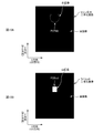
- FIG. 9 is an image diagram of a planar image captured and recorded, that is, a planar image indicated by planar image data.
- the planar image is captured with the CD direction as the X direction and the MD direction as the Y direction, and the planar image is captured as an entire image of the unit packaging sheet 27au.
- Such a planar image is an aggregate of a large number of pixels arranged in a grid at a predetermined pitch based on a predetermined resolution in both the X direction and the Y direction.
- the planar image is composed of a plurality of pixels arranged in a straight line in the X direction at a predetermined pitch and arranged in a plurality of rows at a predetermined pitch in the Y direction.
- the plane image data has color information corresponding to each pixel. In this example, since the plane image data is grayscale, each pixel has only brightness as color information.
- each pixel corresponding to the highly reflective region in the unit packaging sheet 27au becomes bright, the brightness of the pixel is high, but on the other hand, it corresponds to the region with low reflectivity. Since each pixel becomes dark, the lightness of the pixel has a low value.
- the reflectivity of the portion of the unit packaging sheet 27au where the perforation 27M is formed is higher than that of the portion where the perforation 27M is not formed. Therefore, by paying attention to pixels whose brightness is not less than the first threshold, it is possible to specify the pixels in the region A27M where the perforation 27M is imaged on the planar image in FIG.
- the reflectivity of the portion of the unit packaging sheet 27au where the label 28 is bonded is higher than that of the portion where the label 28 is not bonded. Therefore, by paying attention to the pixels whose brightness is the second threshold value or more, it is possible to specify the pixels in the area A28 where the label 28 is captured on the planar image in FIG.
- each of the first threshold value and the second threshold value is stored in advance in the memory.
- the first threshold value is set higher than the second threshold value.
- the present invention is not limited to this, and if the height relationship of reflectivity is the reverse of the above, the height relationship between the first threshold value and the second threshold value is also reversed.
- the binarized image of the perforation 27M in FIG. 10A is generated as follows. First, among the pixels related to the planar image in FIG. 9, a pixel having a brightness equal to or higher than the first threshold is “1” which is one of the two values (for example, 0 and 1) in the binarized image in FIG. 10A. On the other hand, pixels having brightness less than the first threshold value are assigned to the black image specified by the other value “0”. This is performed for all the pixels of the planar image. Thereby, among the pixels in the planar image of FIG. 9, the region A27M where the perforation 27M is imaged is included in the white image in the binarized image as shown in FIG. 10A, and the other portions are black. As a result, the binarized image of the perforation in FIG. 10A is generated.
- the binarized image of the label 28 in FIG. 10B is generated as follows. First, among the pixels related to the planar image of FIG. 9, pixels of brightness included in a numerical range that is greater than or equal to the second threshold value and less than the first threshold value are represented by binary values (for example, 0 and 1) in the binarized image of FIG. 10B. One of the values is assigned to a white image specified by “1”, and on the other hand, pixels having brightness outside the above numerical range are assigned to a black image specified by the other value “0”. This is performed for all the pixels of the planar image. Thereby, among the pixels in the planar image of FIG. 9, the area A28 where the label 28 is imaged is included in the white image in the binarized image as shown in FIG. 10B, and the other parts are black images. As a result, the binarized image of the label 28 in FIG. 10B is generated.
- the image processing unit 66 proceeds to the calculation process of the relative positional relationship information.
- the image processing unit 66 proceeds to the calculation process of the relative positional relationship information.
- the relative positional relationship information is calculated.
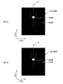
- the top portion 27Mt (corresponding to the “predetermined portion of the weak line”) of the perforation 27M is referred to, and the label
- the end portion 28ed (corresponding to the “predetermined portion of the label”) on the downstream side in the MD direction of the label 28 is referred to as a representative of the joining position 28, and further, as an example of relative positional relationship information
- the distance D between the position of the top portion 27Mt of the substantially chevron shape of the perforation 27M and the position of the downstream end portion 28ed in the MD direction of the label 28 (corresponding to "value corresponding to the size of the distance") I want to ask.
- the position of the top 27Mt of the perforation 27M is obtained as the pixel position P27Mt at which the Y coordinate is minimum in the white image of the binarized image of the perforation 27M in FIG. 10A, and the downstream of the label 28 in the MD direction.
- the position of the side end portion 28ed is obtained as the pixel position P28ed at which the Y coordinate is maximum in the white image of the binarized image labeled 28 in FIG. 10B. Therefore, the image processing unit 66 changes the size of the interval D as the information on the relative positional relationship from the maximum value of the Y coordinate in the white image of the binarized image of the label 28 to the binarized image of the perforation 27M.
- the minimum value of the Y coordinate in the white image is subtracted.
- the image processing unit 66 proceeds to pass / fail determination processing.
- the pass / fail determination process the pass / fail of the joining position of the label 28 is determined by comparing the size of the interval D with a predetermined allowable range.
- the allowable range is stored in the memory in advance in the form of numerical data. For example, in this example, as shown in FIG. 11, since the length of the label 28 in the MD direction is 15 mm, the permissible range is set to a range of 7 m ⁇ 3 mm, that is, a range of 4 mm to 10 mm. If it is within this allowable range, the perforation 27M can be smoothly cut and opened by pinching and pulling up the label 28. After opening, the opening / closing lid 27cap formed accompanying the opening. Can be reliably re-joined to the portion 27ha around the outlet 27h by the adhesive of the label 28 (FIG. 4).
- the image processing unit 66 determines that “the bonding position of the label 28 is acceptable”. On the other hand, if it is out of the allowable range, it is determined that “the bonding position of the label 28 is rejected”. Then, the image processing unit 66 transmits the determination result to the display unit, and the display unit displays the screen.
- the plane image is picked up by the surface 27 a 1 (the label 28 is bonded to one side) of the both surfaces 27 a 1 and 27 a 2 of the continuous body 27 a of the packaging sheet 27.
- This is done by the camera 62 disposed opposite the non-facing surface 27a1), and thereby, the surface 27a1 on the one side is imaged.
- a plate-shaped light shield having a groundless surface 68a facing the opposite surface 27a2 of the one surface 27a1 of the continuous body 27a of the wrapping sheet 27, that is, the other surface 27a2.
- a member 68 is preferably provided.
- the light shielding member 68 having the non-ground surface 68a is provided so as to face the other surface 27a2 which is the surface 27a2 opposite to the one surface 27a1 of the continuous body 27a of the packaging sheet 27.
- the groundless surface 68a is a background of the image capturing portion of the perforation 27M and the label 28 on the planar image related to the planar image data, and is a reflection of the member 69 located on the other side of the light shielding member 68.
- the bending guide member 70 has a pair of guide plates 71, 71 arranged in the MD direction downstream of the joining position Pj of the continuous body 27a of the packaging sheet 27 in the MD direction. .
- Each guide plate 71, 71 is disposed on each side of the CD direction.
- the sealing device 80 is a device 80 that forms the continuous body 21a of the package 21 of the individually packaged product group G11 by sealing the continuous body 27a of the cylindrical packaging sheet 27.
- it has a pair of upper and lower rolls 81a and 81b.
- Each of the rolls 81a and 81b rotates around the rotation axes C81a and C81b along the CD direction, and thereby rotates to send the continuous body 27a of the cylindrical packaging sheet 27 downstream in the MD direction.
- the rotation drive source is a servo motor.
- processed portions 82a and 82b for forming the sealing portion 27s are provided so as to protrude.
- the upper and lower rolls 81a and 81b are driven and rotated in synchronization with the conveying operation of the continuous body 27a of the packaging sheet 27 by a servo motor (not shown) as a drive source. Therefore, when the portion between the individual packaged product groups G11 and G11 in the continuous body 27a of the cylindrical packaging sheet 27 passes between the upper and lower rolls 81a and 81b, the processing portion of the upper roll 81a. 82a and the processing part 82b of the lower roll 81b face each other, and a sealing part 27s is formed in the part. And thereby, each individual packaged goods group G11 is accommodated in the continuous body 27a of the packaging sheet 27, and is sealed. That is, the continuous body 21a of the packaging body 21 of the individually packaged product group G11, that is, the one 21a in which a plurality of packaging bodies 21, 21... Are connected in the MD direction is formed.
- the position of the servo motor drive rotation is also controlled based on the synchronization signal. And thereby, whenever the part between individual packaged goods group G11, G11 passes among the continuous bodies 27a of the packaging sheet 27, the process part 82a and the process part 82b oppose the said part. Thus, the upper and lower rolls 81a and 81b are rotated.
- the cutter apparatus 90 is the apparatus 90 which forms the package 21 of the individual packaged goods group G11 by cut
- the rotation drive source is a servo motor.
- One of the upper and lower rolls 91a and 91b is a cutter blade roll 91a having a cutter blade 92 on the outer peripheral surface, and the other roll 91b is a smooth outer peripheral surface and the cutter blade 92. It is an anvil roll 91b which receives. And when the sealing part 27s passes between these rolls 91a and 91b, the cutter blade 92 of the cutter blade roll 91a that rotates is a continuous body of the packaging body 21 at the cutting position Pc included in the sealing part 27s. By hitting 21a, the continuous body 21a of the package body 21 is cut, whereby the package body 21 is formed.
- the position of the servo motor drive rotation is also controlled based on the synchronization signal.
- the cutter blade roll 91a is rotated so that the cutter blade 92 faces the cutting position Pc of the sealing portion 27s.
- the inspection device 60 makes a determination of failure, it is necessary to adjust the relative positional relationship between the formation position of the perforation 27M and the bonding position of the label 28. Such adjustment is performed by the perforation formation device 40. Or by the labeler device 50.
- the perforation forming apparatus 40 can be adjusted as follows. First, the size of the interval D obtained as information on the relative positional relationship is the target value Dm (the median value Dm of 4 mm to 10 mm, which is the allowable range described above, and the “target value related to the interval”). In the case where the distance is larger than 7 mm, the synchronization signal is advanced and input by the phase corresponding to the absolute value of the difference between the size of the interval D and the target value Dm, thereby forming the perforation 27M. If the position is moved relatively downstream in the MD direction, the distance D can be adjusted to be smaller.
- Dm the median value Dm of 4 mm to 10 mm, which is the allowable range described above, and the “target value related to the interval”.
- the synchronization signal is advanced and input by the phase corresponding to the absolute value of the difference between the size of the interval D and the target value Dm, thereby forming the perforation 27M. If the position is moved relatively downstream in the MD direction, the distance D can be
- the synchronization signal is delayed and input by the phase corresponding to the absolute value of the difference between the size of the interval D and the target value Dm.
- the labeler device 50 can be adjusted as follows. First, when the size of the distance D obtained as information on the relative positional relationship is larger than the target value Dm of 7 mm, it corresponds to the absolute value of the difference between the size of the distance D and the target value Dm. If the set value of the rotation angle value that is the starting point of the feeding operation is changed to a larger value by the amount of the phase to be moved, and the start of the feeding operation of the label paper 28L is relatively delayed, the joining position of the label 28 is relatively Therefore, the distance D can be adjusted so that the distance D becomes smaller.
- the rotation angle signal of the rotation angle signal is equivalent to the phase corresponding to the absolute value of the difference between the size of the interval D and the target value Dm. If the set value is changed to a small value and the start of the feeding operation of the label paper 28L is made relatively early, the joining position of the label 28 moves relatively downstream in the MD direction, and as a result, the interval Adjustment can be made in the direction in which the size of D increases.
- Such adjustment may be performed manually by the operator, or may be automatically performed by the perforation forming device 40 or the labeler device 50.
- the operation is as follows.
- the perforation forming device 40 has an advance button and a delay button for adjustment. And while the operator is pushing the advance button, the rolls 41a and 41b are rotated relatively to the rotation by the synchronization signal, and if the advance button is released, the roll is being pushed. The rotation based on the synchronization signal is resumed while maintaining the phase of the advanced amount. On the other hand, while the operator is pressing the delay button, the rolls 41a and 41b rotate with a relatively delay from the rotation due to the synchronization signal. The rotation based on the synchronization signal is resumed while maintaining the delayed phase. Thus, manual adjustment is realized.
- the perforation forming device 40 has a controller (not shown) that controls the servo motor.
- the controller is a computer or a PLC (programmable logic controller).
- the controller controls the position of the rotation of the servo motor by changing the rotation angle value of the synchronization signal by the amount corresponding to the difference between the size of the interval D and the target value Dm, thereby realizing automatic adjustment. Is done.
- the labeler device 50 has a feed start delay button and a feed start delay button for adjustment. Then, the start of the feeding operation can be delayed if the operator changes the set value of the rotation angle value that is the starting point of the feeding operation to a larger value by pressing the feeding start delay button. On the other hand, the start of the feeding operation can be accelerated by changing the set value of the rotation angle value, which is the starting point of the feeding operation, to a smaller value by pressing the button for speeding up the feeding start.
- the labeler device 50 has a controller (not shown) that controls the servo motor of the winding reel 52 described above.
- the controller is a computer or a PLC.
- a synchronization signal is input to the controller.
- the controller changes the set value of the rotation angle value that becomes the starting point of the above-mentioned feeding operation by the amount corresponding to the difference between the size of the interval D and the target value Dm, thereby realizing automatic adjustment. Is done.
- the permissible range of the formation position itself of the perforation 27M in the continuous body 27a of the packaging sheet 27 is substantially the MD direction of the unit packaging sheet 27au. As long as it is located at the end of the frame, it may not be a big problem, and its allowable range is relatively large. Therefore, it is possible to exclude it from the object of quality control.
- the formation position of the perforation 27 ⁇ / b> M may fluctuate more than the allowable range.
- the perforation in the continuous body 27 a of the packaging sheet 27 is possible.
- the formation position of the eyes 27M is also included in the quality control target.
- the inspection device 60 also inspects the formation position of the perforation 27M in the continuous body 27a of the packaging sheet 27 in addition to the above-described relative positional relationship inspection. Hereinafter, this inspection will be described.
- the image processing unit 66 of the inspection apparatus 60 has an allowable range of the formation position of the perforation 27M in the MD direction, for example, based on the cutting position Pc in FIG. That is, in this example, as already described with reference to FIG. 14, the allowable range is set to a range of 30 mm ⁇ 10 mm from the cutting position Pc. And if the formation position of the top part 27Mt which represents the formation position of the perforation 27M is in this permissible range, it is a pass, and if not, it is a failure. Incidentally, also in this case, the median value of the permissible range (20 mm to 40 mm) is the target formation position of the perforation 27M, that is, the target formation position is 30 mm.
- the image processing unit 66 performs the above pass / fail judgment using the Y coordinate of the formation position of the top portion 27Mt obtained in the above-described calculation process of the relative positional relationship information. That is, pass / fail is determined by comparing the Y coordinate of the formation position of the apex 27Mt with the range of the Y coordinate corresponding to the allowable range.
- the imaging operation of the camera 62 is performed based on the synchronization signal, and similarly, the cutting process at the cutting position Pc by the cutter device 90 is also performed based on the synchronization signal. Therefore, it can also be said that the Y coordinate of the plane image data is expressed on the basis of the cutting position Pc, so that the pass / fail judgment can be made based on the above Y coordinate.
- the image processing unit 66 transmits the message to the display unit, and the display unit displays the screen. Further, although it is necessary to adjust the formation position of the perforation 27M, this adjustment is performed using the perforation forming apparatus 40 as follows.
- the Y coordinate of the formation position of the top 27Mt of the perforation 27M obtained by the image processing unit 66 is smaller than the Y coordinate of the target formation position, the Y coordinate of the formation position of the top 27Mt of the perforation 27M.
- the synchronization signal is advanced and input by a phase corresponding to the absolute value of the difference between the Y coordinate of the target formation position and the target formation position, thereby moving the formation position of the perforation 27M relatively downstream in the MD direction.
- the formation position of the perforation 27M can be adjusted to be within the allowable range.
- the Y coordinate of the formation position of the top portion 27Mt of the perforation 27M is larger than the Y coordinate of the target formation position, the Y coordinate of the formation position of the top portion 27Mt of the perforation 27M and the Y coordinate of the target formation position. If the synchronization signal is delayed and input by the phase corresponding to the absolute value of the difference between the perforation 27M and the formation position of the perforation 27M is relatively moved upstream in the MD direction, the perforation of the perforation 27M The formation position can be adjusted in a direction that falls within an allowable range.
- Such adjustment may be performed manually by the operator, or may be automatically performed by the perforation forming device 40. It is obvious that such manual operation and automatic operation can be realized by a method similar to the method using the advance button or the like exemplified as a method for adjusting the relative positional relationship, or the method using the controller. The explanation is omitted.
- the perforation forming device 40 adjusts the formation position of the perforation 27M in this way, the relative positional relationship with the bonding position of the label 28 also changes accordingly, so the relative positional relationship is also adjusted. Will have to.
- the adjustment of the relative positional relationship is performed by the labeler device 50, and the adjustment method is the same as the adjustment method of the relative positional relationship described above. Therefore, the description is omitted.
- FIG. 12 is an explanatory diagram of a modification of the present embodiment.
- FIG. 12 is a schematic plan view of the packaging sheet 27 in a developed state on a plane.
- the inspection device 60 uses the distance D between the formation position of the perforation 27M and the bonding position of the label 28 as information on the relative positional relationship between the formation position of the perforation 27M and the bonding position of the label 28. And determining pass / fail based on the distance D.
- the size of the interval D is calculated, the calculation load of the image processing unit 66 of the inspection apparatus 60 increases. Then, the image processing unit 66 easily reaches the limit of the processing capability, which is large when it is desired to increase the number of manufactured packaging bodies 21 per unit time when the production plan of the production line is changed. There is a risk of restrictions.
- the label 28 is also a transparent sheet, and the label 28 is provided with an opaque mark 29 (corresponding to a symbol).
- the heart-shaped mark 29 is provided in a solid color.
- the mark 29 is formed corresponding to the region 28Rg on the label 28 where the top portion 27Mt of the perforation 27M is to be positioned when it is determined that it is acceptable.
- the distance D from the downstream end portion 28ed in the MD direction of the label 28 to the top portion 27Mt of the substantially chevron 27M is 7 mm ⁇ 3 mm, that is, 4 mm to 10 mm.
- the mark 29 is provided over the entire range of 4 mm to 10 mm. More specifically, in this example, the substantially mountain-shaped top portion 27Mt is located at the center position in the CD direction, and at the center position in the CD direction, the heart mark 29 is located downstream of the label 28 in the MD direction. It is formed in the range of 4 mm to 10 mm upstream from the end portion 28ed in the MD direction.
- the top 27Mt is overlapped with the mark 29 as shown in FIG. 12, but in the case of failure, the top 27Mt is not overlapped with the mark 29 and is separated from the mark 29. It will be in the state where it was located. Therefore, it is possible to make a pass / fail judgment by detecting whether or not the top 27Mt is in a state where it overlaps the mark 29. As a result, it is possible to make a pass / fail determination without calculating the size of the interval D.
- the detection of whether or not they are in the above-described overlapping state can be performed by binarizing the planar image data imaged and generated by the camera 62 in FIG. 8 described above.
- the image processing unit 66 selects a pixel having a lightness equal to or higher than a predetermined third threshold among the pixels of the planar image indicated by the planar image data, out of the binary values (for example, 0 and 1)
- the white image specified by one value “1” is allocated to the white image, and the pixel having the lightness less than the third threshold value is allocated to the black image specified by the other value “0”. This is performed for all the pixels of the planar image.
- both the area A27M where the perforation 27M is imaged and the area A29 where the mark 29 is imaged are included in the white image in the binarized image.
- a binary image as shown in FIG. 13A or FIG. 13B is generated.
- the pixel corresponding to the center position Cx in the X direction corresponds to the MD direction.
- a transparent sheet is used not only for the continuous body 27 a of the packaging sheet 27 but also for the label 28. Therefore, the mark 29 of the label 28 can also be imaged by the camera 62 through both the continuous body 27 a of the packaging sheet 27 and the label 28.
- the label 28 is not a transparent sheet, it is difficult to image either the perforation 27M or the mark 29 of the label 28 with the camera 62. Therefore, when applying the method of this modification, it is desirable that the label 28 is a transparent sheet or a translucent sheet such as a translucent sheet. Note that the color of the label 28 may be either colored or colorless.
- the heart-shaped mark 29 is illustrated as an example of the design of the label 28, but the present invention is not limited to this.
- it may be a polygonal mark such as a rectangle, a circular mark, or an illustration.
- the symbol 29 is also a part of the label 28.
- the individual package group G11 is illustrated as an example of the hygiene article, but the present invention is not limited thereto. That is, the sanitary article may be an article that is not individually packaged, or may be an article group in which a predetermined number of articles that are not individually packaged are stacked. Moreover, the absorbent article which concerns on a hygiene article may be other than the panty liner 1, for example, a sanitary napkin, a tampon, a disposable diaper, etc. may be sufficient.
- the surface 27a1 of the continuous body 27a of the packaging sheet 27 to which the label 28 is not bonded is imaged, but the present invention is not limited to this. .
- the surface 27a2 to which the label 28 is bonded may be imaged.
- the camera 62 of the inspection apparatus received the reflected light from the continuum 27a of the packaging sheet 27 and captured one surface 27a1 of the both surfaces 27a1 and 27a2, the present invention is not limited to this.
- the illuminating member 64 illuminates the surface 27a2 opposite to the surface 27a1 captured by the camera 62 of the both surfaces 27a1 and 27a2, thereby transmitting the continuous body 27a of the packaging sheet 27 in the thickness direction.
- the transmitted light may be received, and thereby one of the two surfaces 27a1 and 27a2 may be imaged. That is, the camera 62 and the illumination member 64 may be appropriately arranged so that both the perforation 27M and the label 28 are imaged.
- gray scale data in which the color information of each pixel has only brightness is shown as an example of planar image data, but the present invention is not limited to this.
- the color information of each pixel may be color image data having brightness, hue, and saturation.
- color binarization processing may be performed as the above-described binarization processing.
- the synchronization signal a signal obtained by repeatedly outputting each rotation angle value of 0 ° to 360 ° is illustrated, but the present invention is not limited to this.
- a digital signal in which 8192 digital values from 0 to 8191 are repeatedly output may be used, or the synchronization signal may be a signal in which a pulse signal including a plurality of pulses is repeatedly output.
- the synchronization signal is the rotation angle value signal or the digital signal
- the position control of the servo motor using the synchronization signal is performed with the actual position of the servo motor and the command position indicated by the synchronization signal. This is done by controlling the servo motor so that the deviation is smaller.
- the actual position of the servo motor is measured by an appropriate rotational position detector such as an encoder.
- the controller that controls the servo motor calculates a deviation between the number of pulses of the input synchronization signal and the number of pulses output from the rotational position detector of the servo motor.
- a counter for counting is provided, and the rotation of the servo motor is controlled by the controller so that the deviation becomes small.
- the perforation 27M is illustrated as an example of the weak line, but the present invention is not limited to this.
- a half cut line may be used. In other words, if it is a linear portion having a lower strength than the surrounding portion so that it can serve as a guide line for cutting when it is cut, it can be used as the weak line.
- the position of the top 27Mt of the perforation 27M and the label are represented on behalf of each position.
- the position of the end portion 28ed on the downstream side in the MD direction of 28 is referred to, the position to be referred to is not limited to this.
- the position where the perforation 27M is formed may be referred to, and the position of the end portion 27Med on the downstream side in the MD direction in the perforation 27M may be referred to.
- the position of the end portion 28eu on the upstream side in the MD direction of the label 28 may be referred to.
- the position of the top portion 27Mt of the perforation 27M and the position of the end portion 28ed on the downstream side in the MD direction of the label 28 are respectively set to the minimum value of the Y coordinate of the white image of the perforation 27M and the white of the label 28.
- it was obtained based on the maximum value of the Y coordinate of the image it is not limited to this. For example, you may obtain
- the brightness data of the pixels arranged along the Y direction is differentiated with respect to the Y direction, and the value obtained by the differentiation is compared with an appropriate threshold value. Then, the position of the Y coordinate specified by the comparison is set as the position of the top portion 27Mt of the perforation 27M or the position of the end portion 28ed on the downstream side in the MD direction of the label 28.
Landscapes
- Engineering & Computer Science (AREA)
- Mechanical Engineering (AREA)
- Auxiliary Devices For And Details Of Packaging Control (AREA)
- Packages (AREA)
- Containers And Plastic Fillers For Packaging (AREA)
- Packaging Of Annular Or Rod-Shaped Articles, Wearing Apparel, Cassettes, Or The Like (AREA)
- Labeling Devices (AREA)
- Basic Packing Technique (AREA)
Abstract
This manufacturing method for a packaged body comprises: conveying a plurality of sanitary articles in the conveying direction, and conveying such that there is a space between sanitary articles adjacent in the conveying direction; forming, at sections corresponding to sanitary articles, weakened lines in a continuous body of a packaging sheet that is continuous in the conveying direction; bonding a label per weakened line to the continuous body of the packaging sheet; determining whether the bonding position of each label on the packaging sheet is acceptable on the basis of the relative positions of the weakened line and the label on the continuous body of the packaging sheet; wrapping sanitary articles with the continuous body of the packaging sheet by respectively folding the ends of the continuous body of the packaging sheet in the intersecting direction that intersects with the conveying direction; forming seal portions in the continuous body of packaging sheet at sections thereof between sanitary articles in order to seal the continuous body of the packaging sheet with the sanitary articles wrapped therein; and generating packaged bodies formed from packaging the sanitary articles, by cutting the continuous body of the packaging sheet at cutting positions set at said sections. To determine said acceptability, the weakened lines in the continuous body of the packaging sheet and the labels are imaged to generate image data of the weakened lines and the labels, and said acceptability is determined according to the relative positions of specified weakened lines and labels on the basis of the image data.
Description
本発明は、ポケットタイプのウエットティッシュ等の衛生物品の包装体の製造方法、及び製造装置に関する。
The present invention relates to a method and apparatus for manufacturing a package of sanitary articles such as pocket-type wet tissue.
従来、ポケットタイプのウエットティッシュやパンティーライナー等の衛生物品は、複数枚単位で一つの包装シートに包装された包装体の形態で市場に提供されている。そして、かかる衛生物品は、例えば一枚ずつ包装シートから取り出して使用される。
Conventionally, sanitary articles such as pocket-type wet tissues and panty liners are provided to the market in the form of a package packaged in a single packaging sheet. And this hygiene article is taken out from a packaging sheet, for example one by one, and used.
特許文献1には、かかる包装体の一例として、包装シートの開封後に、開閉自在な蓋が形成される技術が開示されている。
Patent Document 1 discloses a technique in which an openable / closable lid is formed after opening a packaging sheet as an example of such a package.
以下、後述する図2A、図2B、及び図4を代用しながら、特許文献1に開示された包装シート27について概略説明する。
Hereinafter, the packaging sheet 27 disclosed in Patent Document 1 will be schematically described with reference to FIGS. 2A, 2B, and 4 described later.
図2A及び図2Bに示すように、先ず、包装シート27には、所定部分27capをほぼ囲むようにミシン目27Mが形成されており、また、ミシン目27Mに対応する部分にはラベル28が接合されている。そして、かかる包装シート27の開封は、ラベル28をつまんで引き上げることにより、上記ミシン目27Mを切断してなされる。すなわち、これにより、図4に示すように、上記の所定部分27capは概ね包装シート27から分離されて、包装シート27には、所定部分27capに対応した形状の取り出し口27hが形成される。
As shown in FIGS. 2A and 2B, the packaging sheet 27 is first formed with perforations 27M so as to substantially surround the predetermined portion 27cap, and a label 28 is joined to the portion corresponding to the perforations 27M. Has been. The packaging sheet 27 is opened by cutting the perforation 27M by picking up the label 28 and pulling it up. That is, as shown in FIG. 4, the predetermined portion 27cap is generally separated from the packaging sheet 27, and the packaging sheet 27 is formed with an outlet 27h having a shape corresponding to the predetermined portion 27cap.
なお、このときには、同所定部分27capは、完全には包装シート27から分離されてはおらず、つまり、ミシン目27Mの未形成部分27Mbを介して包装シート27に接続されている。そのため、当該所定部分27capは、この未形成部分27Mbをヒンジとして開閉可能な開閉蓋27capとなっている。また、ラベル28は、主に包装シート27のうちで開閉蓋27capとなる上記所定部分27capに粘着剤で接合されていて、これにより、開封後のラベル28は開閉蓋27capと一体になって開閉動作をするが、ここで、ラベル28は、開閉蓋27capの先端部27Mtよりも飛び出しており、この飛び出した部分28pの粘着剤によって包装シート27の取り出し口27hの周囲の部分27haに再接合可能となっている。
At this time, the predetermined portion 27cap is not completely separated from the packaging sheet 27, that is, is connected to the packaging sheet 27 via the unformed portion 27Mb of the perforation 27M. Therefore, the predetermined portion 27cap is an open / close lid 27cap that can be opened and closed with the unformed portion 27Mb as a hinge. Further, the label 28 is bonded to the predetermined portion 27cap, which mainly becomes the opening / closing lid 27cap, of the packaging sheet 27 with an adhesive, whereby the opened label 28 is opened / closed integrally with the opening / closing lid 27cap. Here, the label 28 protrudes from the tip portion 27Mt of the opening / closing lid 27cap, and can be rejoined to the portion 27ha around the take-out port 27h of the packaging sheet 27 by the adhesive of the protruding portion 28p. It has become.
よって、当該包装体21の使用者は、包装シート27の取り出し口27hからウエットティッシュ等の衛生物品を取り出す度に、何度でも開閉蓋27capで取り出し口27hを閉じた状態に固定することができる。そして、これにより、衛生物品を清潔に保ちながらカバンに仕舞える等、使い易いものとなっている。
Therefore, each time the user of the package 21 takes out a hygienic article such as wet tissue from the take-out port 27h of the package sheet 27, the user can fix the take-out port 27h in the closed state with the open / close lid 27cap. . As a result, it is easy to use, for example, the sanitary article can be put into a bag while being kept clean.
ところで、この特許文献1には、かかる包装体21の製造方法については一切開示されていないが、この製造方法の参考例として、例えば、次のような方法が考えられる。なお、ここでは、後述の図5A乃至図5Cを代用しながら、当該方法について概略説明する。
By the way, although this patent document 1 does not disclose any method for manufacturing such a package 21, as a reference example of this manufacturing method, for example, the following method can be considered. Here, the method will be outlined with reference to FIGS. 5A to 5C described later.
先ず、コンベア等の搬送装置32によって、衛生物品G11を、搬送方向(MD方向)に沿って所定の搬送ピッチPG11で搬送する。なお、搬送方向に隣り合う衛生物品G11、G11同士の間には、上記の所定ピッチPG11に基づいて間隔があけられている。
First, the sanitary article G11 is transported at a predetermined transport pitch PG11 along the transport direction (MD direction) by the transport device 32 such as a conveyor. Note that a space is provided between the sanitary articles G11 and G11 adjacent in the transport direction based on the predetermined pitch PG11.
また、別の搬送装置34では、搬送方向に連続する包装シート27の連続体27aを搬送しており、そして、この搬送方向の所定位置には、ミシン目形成装置40とラベラー装置50とがこの順番で配置されている。よって、ミシン目形成装置40を通過する際には、同連続体27aのうちで衛生物品G11に対応する部分にミシン目27Mが形成され、そして、ラベラー装置50を通過する際には、同連続体27aに対してミシン目27M毎にラベル28が接合される。
Further, another transporting device 34 transports the continuous body 27a of the packaging sheet 27 continuous in the transporting direction, and the perforation forming device 40 and the labeler device 50 are located at predetermined positions in the transporting direction. Arranged in order. Therefore, when passing through the perforation forming device 40, the perforation 27M is formed in the portion corresponding to the sanitary article G11 in the continuous body 27a, and when passing through the labeler device 50, the continuous A label 28 is bonded to the body 27a for each perforation 27M.
そして、しかる後に、かかる包装シート27の連続体27aは、衛生物品G11を搬送する上記の搬送装置32に合流されるが、かかる合流後には、折り曲げガイド部材70を通過する。そして、その通過中には、包装シート27の連続体27aにおいて搬送方向と交差する幅方向(CD方向)の各端部27aew,27aewが、それぞれ折り曲げられて同連続体27aは筒状にされ、これにより、同連続体27aは、衛生物品G11を包み込んだ状態にされる。
Then, after that, the continuous body 27a of the packaging sheet 27 is joined to the transport device 32 that transports the sanitary article G11. After the joining, the continuous body 27a passes through the bending guide member 70. During the passage, the end portions 27aew and 27aew in the width direction (CD direction) intersecting the transport direction in the continuous body 27a of the packaging sheet 27 are bent, respectively, so that the continuous body 27a is formed into a cylindrical shape. As a result, the continuum 27a is encased in the sanitary article G11.
そうしたら、搬送方向の下流のシール装置80を通過する際に、当該シール装置80は、衛生物品G11を包んだ状態で包装シート27の連続体27aを封止すべく、包装シート27の連続体27aのうちの衛生物品G11,G11同士の間の部分に封止部27sを形成する。
Then, when passing through the sealing device 80 downstream in the transport direction, the sealing device 80 seals the continuum 27a of the packaging sheet 27 in a state of wrapping the sanitary article G11. 27s of sealing parts are formed in the part between hygiene articles G11 and G11 among 27a.
そして、最後に、カッター装置90の位置を通過する際に、当該カッター装置90は、封止部27sに含まれる位置を切断位置Pcとして包装シート27の連続体27aを切断し、以上をもって、衛生物品G11を包装してなる包装体21が生成される。
And finally, when passing the position of the cutter apparatus 90, the said cutter apparatus 90 cut | disconnects the continuous body 27a of the packaging sheet 27 by making the position contained in the sealing part 27s into the cutting position Pc, and has the above. A package 21 formed by packaging the article G11 is generated.
ここで、かかる製造時には、所期の製品仕様に包装体21を仕上げるために品質管理がなされている。そして、ミシン目27Mの形成位置やラベル28の接合位置も、品質管理の対象である。
Here, at the time of manufacturing, quality control is performed in order to finish the package 21 to the expected product specifications. The formation position of the perforation 27M and the joining position of the label 28 are also objects of quality control.
例えば、図14に示すように、包装シート27の連続体27aにおいて開閉蓋27capの先端部となるミシン目27Mの部分27Mtの搬送方向の形成位置が、上記の切断位置Pcから例えば30mm±10mmの範囲に入るように管理され、また、ラベル28の搬送方向の下流端部28edの接合位置が、同切断位置Pcから例えば23mm±5mmの範囲に入るように管理されている。つまり、どちらの位置も、切断位置Pcを基準として管理されている。そして、これに伴って、これら範囲から外れたものは、不合格とされ、すなわち不良品とされて廃棄される。
For example, as shown in FIG. 14, in the continuous body 27a of the packaging sheet 27, the formation position in the transport direction of the portion 27Mt of the perforation 27M that becomes the tip of the opening / closing lid 27cap is, for example, 30 mm ± 10 mm from the cutting position Pc. The joining position of the downstream end portion 28ed in the conveyance direction of the label 28 is managed so as to fall within a range of, for example, 23 mm ± 5 mm from the cutting position Pc. That is, both positions are managed based on the cutting position Pc. Along with this, those out of these ranges are rejected, that is, rejected and discarded.
しかしながら、ラベル28の機能が、開封時につまんで引き上げることによりミシン目27Mを確実に切って開封するものであること、並びに、開封後には、ラベル28の粘着剤によって開閉蓋27capを閉じた状態に固定するものであることを考え合わせると、ラベル28の接合位置の管理範囲を、切断位置Pcを基準に定めるよりは、ミシン目27Mの形成位置を基準に定めた方が、妥当なものと考えられる。そして、このことから、ラベル28の接合位置の合否の判定についても、ミシン目27Mの形成位置を基準に行った方が、上述のようなラベル28の機能をしっかり奏するものを、合格と判定することができて、つまり、ラベル28の接合位置の合否の判定を適正に行えるものと考えられる。
However, the function of the label 28 is that the perforation 27M is surely cut and opened by pinching and lifting at the time of opening, and the opening / closing lid 27cap is closed by the adhesive of the label 28 after opening. Considering that it is fixed, it is considered more appropriate to set the management range of the bonding position of the label 28 based on the formation position of the perforation 27M rather than the cutting position Pc. It is done. And from this, it is determined that the one that performs the function of the label 28 as described above is acceptable when the determination is made based on the formation position of the perforation 27M for the determination of pass / fail of the bonding position of the label 28. In other words, it is considered that it is possible to appropriately determine whether or not the joining position of the label 28 is acceptable.
本発明は、上記のような従来の問題に鑑みてなされたものであって、その目的は、ミシン目等の脆弱線に沿って切られることにより開封後に開閉蓋が形成される包装シートで衛生物品が包装されてなる包装体を製造する際に、ラベルの接合位置の合否の判定を適正に行えるようにすることにある。
The present invention has been made in view of the above-described conventional problems, and its purpose is to provide a hygienic package sheet in which an opening / closing lid is formed after opening by being cut along a weak line such as a perforation. In manufacturing a package in which an article is packaged, it is possible to appropriately determine whether a label joining position is acceptable.
上記目的を達成するための主たる発明は、
包装シートによって少なくとも一つの衛生物品が包装されてなる包装体の製造方法であって、
前記衛生物品を包装している前記包装シートは、開封時に脆弱線に沿って切られることにより開封後に開閉蓋となる部分を有するとともに、前記包装シートにおける前記脆弱線に対応する部分には、開封時につまみとなるラベルが、開封後には前記開閉蓋を閉じた状態で固定可能なように接合されており、
前記製造方法は、
複数の前記衛生物品を搬送方向に沿って搬送することであって、前記搬送方向に隣り合う前記衛生物品同士の間に間隔をあけた状態で搬送することと、
前記搬送方向に連続する前記包装シートの連続体のうちで前記衛生物品に対応する部分に前記脆弱線を形成することと、
前記包装シートの連続体に対して前記脆弱線毎に前記ラベルを接合することと、
前記包装シートの連続体における前記脆弱線と前記ラベルとの相対位置関係に基づいて、前記包装シートにおける前記ラベルの接合位置の合否を判定することと、
前記包装シートの連続体において前記搬送方向と交差する交差方向の各端部を、それぞれ折り曲げることにより、前記包装シートの連続体で前記衛生物品を包むことと、
前記衛生物品を包んだ状態で前記包装シートの連続体を封止すべく、前記包装シートの連続体のうちの前記衛生物品同士の間の部分に封止部を形成することと、
前記部分に設定された切断位置で前記包装シートの連続体を切断することにより、前記衛生物品を包装してなる前記包装体を生成することと、を有し、
前記合否を判定することにおいては、
前記包装シートの連続体における前記脆弱線と前記ラベルとを撮像することにより、前記脆弱線と前記ラベルとの画像データを生成し、前記画像データに基づいて特定される前記脆弱線と前記ラベルとの相対位置関係によって前記合否を判定することを特徴とする衛生物品の包装体の製造方法である。 The main invention for achieving the above object is:
A method for producing a package in which at least one sanitary article is packaged by a packaging sheet,
The packaging sheet that packages the sanitary article has a portion that becomes an opening / closing lid after opening by being cut along the line of weakness when opened, and a portion corresponding to the line of weakness in the packaging sheet is opened A label that sometimes becomes a knob is joined so that it can be fixed with the opening and closing lid closed after opening,
The manufacturing method includes:
Transporting a plurality of the sanitary articles along a transport direction, transporting the sanitary articles adjacent to each other in the transport direction with a gap therebetween;
Forming the line of weakness in a portion corresponding to the sanitary article in a continuous body of the packaging sheet continuous in the transport direction;
Bonding the label for each line of weakness to the continuum of the packaging sheet;
Determining pass / fail of the bonding position of the label in the packaging sheet based on the relative positional relationship between the weak line and the label in the continuum of the packaging sheet;
Wrapping the sanitary article in the continuum of the packaging sheet by bending each end in the crossing direction intersecting the transport direction in the continuum of the packaging sheet;
Forming a sealing portion in a portion between the sanitary articles in the continuum of the packaging sheets in order to seal the continuum of the packaging sheets in a state of wrapping the sanitary articles;
Generating the package formed by packaging the sanitary article by cutting the continuous body of the packaging sheet at the cutting position set in the part,
In determining the pass / fail,
By imaging the weak line and the label in the continuum of the packaging sheet, the image data of the weak line and the label is generated, and the weak line and the label specified based on the image data It is the manufacturing method of the package body of the hygiene article characterized by determining the said pass / failure by relative positional relationship.
また、
包装シートによって少なくとも一つの衛生物品が包装されてなる包装体の製造装置であって、
前記衛生物品を包装している前記包装シートは、開封時に脆弱線に沿って切られることにより開封後に開閉蓋となる部分を有するとともに、前記包装シートにおける前記脆弱線に対応する部分には、開封時につまみとなるラベルが、開封後には前記開閉蓋を閉じた状態で固定可能なように接合されており、
前記製造装置は、
複数の前記衛生物品を搬送方向に沿って搬送する装置であって、前記搬送方向に隣り合う前記衛生物品同士の間に間隔をあけた状態で搬送する前記装置と、
前記搬送方向に連続する前記包装シートの連続体のうちで前記衛生物品に対応する部分に前記脆弱線を形成する装置と、
前記包装シートの連続体に対して前記脆弱線毎に前記ラベルを接合する装置と、
前記包装シートの連続体における前記脆弱線と前記ラベルとの相対位置関係に基づいて、前記包装シートにおける前記ラベルの接合位置の合否を判定する装置と、
前記包装シートの連続体において前記搬送方向と交差する交差方向の各端部を、それぞれ折り曲げることにより、前記包装シートの連続体で前記衛生物品を包む装置と、
前記衛生物品を包んだ状態で前記包装シートの連続体を封止すべく、前記包装シートの連続体のうちの前記衛生物品同士の間の部分に封止部を形成する装置と、
前記部分に設定された切断位置で前記包装シートの連続体を切断することにより、前記衛生物品を包装してなる前記包装体を生成する装置と、を有し、
前記合否を判定する装置は、
前記包装シートの連続体における前記脆弱線と前記ラベルとを撮像することにより、前記脆弱線と前記ラベルとの画像データを生成し、前記画像データに基づいて特定される前記脆弱線と前記ラベルとの相対位置に基づいて合否を判定することを特徴とする衛生物品の包装体の製造装置である。 Also,
An apparatus for manufacturing a package in which at least one sanitary article is packaged by a packaging sheet,
The packaging sheet that packages the sanitary article has a portion that becomes an opening / closing lid after opening by being cut along the line of weakness when opened, and a portion corresponding to the line of weakness in the packaging sheet is opened A label that sometimes becomes a knob is joined so that it can be fixed with the opening and closing lid closed after opening,
The manufacturing apparatus includes:
An apparatus for conveying a plurality of the hygiene articles along a conveying direction, wherein the apparatus conveys the sanitary articles adjacent to each other in the conveying direction with a gap therebetween;
An apparatus for forming the line of weakness in a portion corresponding to the sanitary article in the continuous body of the packaging sheet that is continuous in the transport direction;
An apparatus for joining the label for each line of weakness with respect to the continuous body of the packaging sheet;
An apparatus for determining pass / fail of the bonding position of the label in the packaging sheet, based on the relative positional relationship between the weak line and the label in the continuum of the packaging sheet;
An apparatus for wrapping the sanitary article in the continuum of the packaging sheet by bending each end in the intersecting direction intersecting the transport direction in the continuum of the packaging sheet;
An apparatus for forming a sealing portion in a portion between the sanitary articles in the continuum of the packaging sheets to seal the continuum of the packaging sheets in a state of wrapping the sanitary articles;
An apparatus for generating the package by packaging the sanitary article by cutting the continuous body of the packaging sheet at the cutting position set in the part,
The apparatus for determining pass / fail is:
By imaging the weak line and the label in the continuum of the packaging sheet, the image data of the weak line and the label is generated, and the weak line and the label specified based on the image data It is a manufacturing apparatus of the packaging body of the hygiene article characterized by determining the pass / fail based on the relative position of.
本発明の他の特徴については、本明細書及び添付図面の記載により明らかにする。
Other features of the present invention will be clarified by the description of the present specification and the accompanying drawings.
本発明によれば、ミシン目等の脆弱線に沿って切られることにより開封後に開閉蓋が形成される包装シートで衛生物品が包装されてなる包装体を製造する際に、ラベルの接合位置の合否の判定を適正に行うことができる。
According to the present invention, when manufacturing a package body in which hygiene articles are packaged by a packaging sheet in which an opening / closing lid is formed after opening by being cut along a weak line such as a perforation, Pass / fail judgment can be performed appropriately.
本明細書及び添付図面の記載により、少なくとも以下の事項が明らかとなる。
At least the following matters will become clear from the description of this specification and the accompanying drawings.
包装シートによって少なくとも一つの衛生物品が包装されてなる包装体の製造方法であって、
前記衛生物品を包装している前記包装シートは、開封時に脆弱線に沿って切られることにより開封後に開閉蓋となる部分を有するとともに、前記包装シートにおける前記脆弱線に対応する部分には、開封時につまみとなるラベルが、開封後には前記開閉蓋を閉じた状態で固定可能なように接合されており、
前記製造方法は、
複数の前記衛生物品を搬送方向に沿って搬送することであって、前記搬送方向に隣り合う前記衛生物品同士の間に間隔をあけた状態で搬送することと、
前記搬送方向に連続する前記包装シートの連続体のうちで前記衛生物品に対応する部分に前記脆弱線を形成することと、
前記包装シートの連続体に対して前記脆弱線毎に前記ラベルを接合することと、
前記包装シートの連続体における前記脆弱線と前記ラベルとの相対位置関係に基づいて、前記包装シートにおける前記ラベルの接合位置の合否を判定することと、
前記包装シートの連続体において前記搬送方向と交差する交差方向の各端部を、それぞれ折り曲げることにより、前記包装シートの連続体で前記衛生物品を包むことと、
前記衛生物品を包んだ状態で前記包装シートの連続体を封止すべく、前記包装シートの連続体のうちの前記衛生物品同士の間の部分に封止部を形成することと、
前記部分に設定された切断位置で前記包装シートの連続体を切断することにより、前記衛生物品を包装してなる前記包装体を生成することと、を有し、
前記合否を判定することにおいては、
前記包装シートの連続体における前記脆弱線と前記ラベルとを撮像することにより、前記脆弱線と前記ラベルとの画像データを生成し、前記画像データに基づいて特定される前記脆弱線と前記ラベルとの相対位置関係によって前記合否を判定することを特徴とする衛生物品の包装体の製造方法である。 A method for producing a package in which at least one sanitary article is packaged by a packaging sheet,
The packaging sheet that packages the sanitary article has a portion that becomes an opening / closing lid after opening by being cut along the line of weakness when opened, and a portion corresponding to the line of weakness in the packaging sheet is opened A label that sometimes becomes a knob is joined so that it can be fixed with the opening and closing lid closed after opening,
The manufacturing method includes:
Transporting a plurality of the sanitary articles along a transport direction, transporting the sanitary articles adjacent to each other in the transport direction with a gap therebetween;
Forming the line of weakness in a portion corresponding to the sanitary article in a continuous body of the packaging sheet continuous in the transport direction;
Bonding the label for each line of weakness to the continuum of the packaging sheet;
Determining pass / fail of the bonding position of the label in the packaging sheet based on the relative positional relationship between the weak line and the label in the continuum of the packaging sheet;
Wrapping the sanitary article in the continuum of the packaging sheet by bending each end in the crossing direction intersecting the transport direction in the continuum of the packaging sheet;
Forming a sealing portion in a portion between the sanitary articles in the continuum of the packaging sheets in order to seal the continuum of the packaging sheets in a state of wrapping the sanitary articles;
Generating the package formed by packaging the sanitary article by cutting the continuous body of the packaging sheet at the cutting position set in the part,
In determining the pass / fail,
By imaging the weak line and the label in the continuum of the packaging sheet, the image data of the weak line and the label is generated, and the weak line and the label specified based on the image data It is the manufacturing method of the package body of the hygiene article characterized by determining the said pass / failure by relative positional relationship.
このような衛生物品の包装体の製造方法によれば、ラベルの接合位置の合否の判定を、脆弱線とラベルとの相対位置関係に基づいて行う。よって、ラベルの接合位置の合否の判定を適正に行うことができる。
に よ According to such a method for manufacturing a package of hygienic articles, determination of pass / fail of the bonding position of the label is performed based on the relative positional relationship between the weak line and the label. Therefore, it is possible to appropriately determine whether the label joining position is acceptable.
また、かかる合否の判定は、包装シートの連続体における脆弱線とラベルとを撮像して生成された画像データに基づいて行われる。よって、合否の判定を正確に行うことができる。
In addition, the determination of pass / fail is performed based on image data generated by imaging the weak line and the label in the continuum of the packaging sheet. Therefore, the pass / fail determination can be performed accurately.
かかる衛生物品の包装体の製造方法であって、
前記撮像することは、前記包むことよりも前に行われるのが望ましい。 A method of manufacturing a package for such a hygiene article,
The imaging is preferably performed before the wrapping.
前記撮像することは、前記包むことよりも前に行われるのが望ましい。 A method of manufacturing a package for such a hygiene article,
The imaging is preferably performed before the wrapping.
このような衛生物品の包装体の製造方法によれば、包む前に包装シートの連続体を撮像し、そして、かかるタイミングで撮像された画像データには、包装シートの連続体が略平面の状態における脆弱線とラベルとの相対位置関係が示されている。そのため、かかる相対位置関係は極めて正確である。そして、この正確に示された相対位置関係に基づいて、ラベルの接合位置の合否の判定を行うので、当該合否の判定精度を向上することができる。
According to such a method for manufacturing a package of hygienic articles, a continuum of packaging sheets is imaged before wrapping, and the image data captured at such timing is in a state in which the continuum of packaging sheets is substantially flat. The relative positional relationship between the line of weakness and the label is shown. Therefore, this relative positional relationship is extremely accurate. And since the determination of the pass / fail of the bonding position of the label is performed based on the relative positional relationship shown correctly, the determination accuracy of the pass / fail can be improved.
かかる衛生物品の包装体の製造方法であって、
前記包装シートの連続体は、互いに直交する三方向として、前記連続体が連続する連続方向と、厚さ方向と、幅方向とを有し、
前記包装シートは、前記厚さ方向の一方側から他方側が透けて見えるシートであり、
前記撮像することはカメラによってなされ、前記カメラは、前記包装シートの連続体の前記一方側の面を撮像し、
前記カメラが撮像する前記一方側の面の逆側の面たる前記他方側の面に対向して、無地面を有した遮光部材が設けられているのが望ましい。 A method of manufacturing a package for such a hygiene article,
The continuous body of the packaging sheet has, as three directions orthogonal to each other, a continuous direction in which the continuous body continues, a thickness direction, and a width direction,
The packaging sheet is a sheet through which the other side can be seen through from one side in the thickness direction,
The imaging is performed by a camera, and the camera images the surface of the one side of the continuous body of the packaging sheet,
It is desirable that a light-shielding member having a non-ground surface is provided so as to face the other surface, which is the surface opposite to the one surface captured by the camera.
このような衛生物品の包装体の製造方法によれば、透けて見える包装シートの連続体を用いたことが原因でラベルの接合位置の合否の判定精度が低下してしまう事態を有効に防ぐことができる。詳しくは、次の通りである。先ず、厚さ方向の反対側が透けて見える包装シートの連続体の場合、カメラで包装シートの連続体の一方側の面を撮像して得られた画像データの画像には、包装シートの連続体よりも厚さ方向の他方側に位置する無関係の部材が写り込んでしまう恐れがあって、かかる写り込みは、上記の合否の判定において誤判定の一因となる。そして、この点につき、上記の製造方法では、包装シートの連続体の一方側の面の逆側の面たる他方側の面に対向させて、無地面を有した遮光部材が設けられていて、かかる無地面は、遮光部材よりも他方側に位置する部材の写り込みを防止する。よって、透けて見える包装シートの連続体を用いた場合に起こり得る合否の判定の精度低下を防ぐことができる。
According to such a method for manufacturing a package of hygienic articles, it is possible to effectively prevent a situation in which the accuracy of determining the pass / fail of the bonding position of the label is reduced due to the use of a continuous package sheet that can be seen through. Can do. Details are as follows. First, in the case of a continuum of packaging sheets that can be seen through the opposite side in the thickness direction, the image of the image data obtained by imaging one side of the continuum of packaging sheets with a camera includes a continuum of packaging sheets. There is a possibility that an irrelevant member positioned on the other side in the thickness direction may be reflected, and this reflection causes an erroneous determination in the above pass / fail determination. And in this respect, in the above manufacturing method, a light shielding member having a non-ground surface is provided so as to face the other surface which is the opposite surface of the one surface of the continuum of the packaging sheet, Such a non-ground prevents reflection of a member located on the other side of the light shielding member. Therefore, it is possible to prevent a decrease in accuracy of pass / fail judgment that can occur when a continuous body of packaging sheets that can be seen through is used.
かかる衛生物品の包装体の製造方法であって、
前記合否を判定することにおいては、前記画像データに基づいて、前記脆弱線の所定部分と前記ラベルの所定部分との間の間隔の大きさに相当する値を、前記相対位置関係を示す情報として算出し、
算出された前記値が、予め規定されている許容範囲に含まれる場合に、合格と判定するのが望ましい。 A method of manufacturing a package for such a hygiene article,
In determining pass / fail, based on the image data, a value corresponding to the size of the interval between the predetermined portion of the weak line and the predetermined portion of the label is used as information indicating the relative positional relationship. Calculate
When the calculated value is included in a predetermined allowable range, it is desirable to determine that the value is acceptable.
このような衛生物品の包装体の製造方法によれば、脆弱線の所定部分とラベルの所定部分との間の間隔の大きさに相当する値を、相対位置関係を示す情報として用いて合否の判定を行う。よって、かかる判定を正確且つ確実に行うことができる。
According to such a method for manufacturing a package of hygiene articles, a value corresponding to the size of the gap between the predetermined portion of the weak line and the predetermined portion of the label is used as information indicating the relative positional relationship. Make a decision. Therefore, this determination can be performed accurately and reliably.
かかる衛生物品の包装体の製造方法であって、
前記間隔に係る目標値を予め有し、
前記算出された前記値の前記目標値からの差を求め、
求められた前記差が小さくなるように、前記脆弱線の形成位置及び前記ラベルの接合位置のうちの少なくともどちらか一方を前記搬送方向に変更するのが望ましい。 A method of manufacturing a package for such a hygiene article,
It has a target value related to the interval in advance,
Obtaining a difference between the calculated value and the target value;
It is desirable to change at least one of the formation position of the weak line and the joining position of the label in the transport direction so that the obtained difference is reduced.
このような衛生物品の包装体の製造方法によれば、上記の差が小さくなるように、脆弱線の形成位置及びラベルの接合位置のうちの少なくともどちらか一方を搬送方向に変更する。よって、ラベルの接合位置の合否の判定が合格となる方向に確実に調整することができる。
According to such a method for manufacturing a package of hygienic articles, at least one of the position where the weak line is formed and the position where the label is joined is changed in the transport direction so that the above-described difference is reduced. Therefore, it can adjust reliably in the direction in which the determination of the pass / fail of the bonding position of the label is acceptable.
かかる衛生物品の包装体の製造方法であって、
前記合否を判定することにおいては、
前記画像データを第1閾値に基づいて二値化処理して第1の二値化画像を生成する際に、前記第1の二値化画像において二値のうちの一方の値によって特定される画像に、前記画像データが示す画像上の前記脆弱線の撮像部分が含まれるように二値化処理を行い、
前記画像データを第2閾値に基づいて二値化処理して第2の二値化画像を生成する際に、前記第2の二値化画像において二値のうちの一方の値によって特定される画像に、前記画像データが示す画像上の前記ラベルの撮像部分が含まれるように二値化処理を行い、
前記第1の二値化画像における前記脆弱線の撮像部分の位置、及び前記第2の二値化画像における前記ラベルの撮像部分の位置との両者に基づいて、前記脆弱線と前記ラベルとの前記相対位置関係を示す情報を生成するのが望ましい。 A method of manufacturing a package for such a hygiene article,
In determining the pass / fail,
When generating the first binarized image by binarizing the image data based on the first threshold value, the first binarized image is specified by one of the two values. Binarization processing is performed so that the image includes the imaging portion of the weak line on the image indicated by the image data,
When the image data is binarized based on a second threshold to generate a second binarized image, the second binarized image is specified by one of the binaries. Binarization processing is performed so that the image includes the imaging portion of the label on the image indicated by the image data,
Based on both the position of the imaging portion of the weak line in the first binarized image and the position of the imaging portion of the label in the second binarized image, the weak line and the label It is desirable to generate information indicating the relative positional relationship.
このような衛生物品の包装体の製造方法によれば、第1閾値に基づいて、脆弱線の撮像部分の位置の特定に特化した第1の二値化画像を生成し、また、第2閾値に基づいて、ラベルの撮像部分の位置の特定に特化した第2の二値化画像を生成する。そして、これら第1及び第2の二値化画像に基づいて脆弱線とラベルとの相対位置関係を示す情報を生成する。よって、当該相対位置関係を示す情報に基づいて、ラベルの接合位置の合否の判定を正確に行うことができる。
According to such a method for manufacturing a package of hygiene articles, a first binarized image specialized in specifying the position of the imaging portion of the weak line is generated based on the first threshold, and the second Based on the threshold value, a second binarized image specialized for specifying the position of the imaging portion of the label is generated. And the information which shows the relative positional relationship of a weak line and a label is produced | generated based on these 1st and 2nd binarized images. Therefore, it is possible to accurately determine whether or not the label joining position is acceptable based on the information indicating the relative positional relationship.
かかる衛生物品の包装体の製造方法であって、
前記脆弱線は、前記包装シートの連続体において前記開閉蓋のヒンジとなる部分には設定されず、
前記ヒンジとなる部分よりも前記搬送方向の一方側に、前記脆弱線のうちで前記開閉蓋の先端部となる部分が位置するように前記脆弱線は形成され、
前記脆弱線のうちで前記先端部となる部分を前記ラベルが覆うように前記ラベルは前記包装シートの連続体に接合され、
前記合否を判定することは、前記脆弱線のうちで前記開閉蓋の前記先端部となる部分と前記ラベルとの相対位置関係に基づいてなされるのが望ましい。 A method of manufacturing a package for such a hygiene article,
The line of weakness is not set in the portion that becomes the hinge of the opening / closing lid in the continuous body of the packaging sheet,
The fragile line is formed such that a portion of the fragile line that becomes the tip of the opening / closing lid is located on one side in the transport direction from the part that becomes the hinge,
The label is joined to the continuum of the packaging sheet so that the label covers the portion that becomes the tip of the weakened line,
It is preferable that the pass / fail judgment is made based on a relative positional relationship between a portion of the weakened line that becomes the tip of the opening / closing lid and the label.
このような衛生物品の包装体の製造方法によれば、ラベルは、脆弱線のうちで開閉蓋の先端部となる部分を搬送方向に横断して接合され、これにより、ラベルは、開封時につまみとして機能し、また、開封後には開閉蓋を閉じた状態に固定する固定部材として機能する。従って、上記の開閉蓋の先端部なる部分は、ラベルに上記機能を確実に発揮させる意味で重要な部分である。他方、上記製造方法によれば、かかる脆弱線のうちで開閉蓋の先端部となる部分を、相対位置関係における一方の着目対象としており、これにより、開閉蓋の先端部となる部分とラベルとの相対位置関係を正確に算出することができる。よって、ラベルが上記の機能を奏するものを、合格と判定することができる。
According to such a method for manufacturing a package of hygienic articles, the label is joined across the portion of the weak line that becomes the tip of the opening / closing lid in the transport direction, whereby the label is pinched at the time of opening. In addition, it functions as a fixing member that fixes the opening / closing lid in a closed state after opening. Therefore, the part which becomes the front-end | tip part of said opening-and-closing lid | cover is an important part in the meaning that the said function is exhibited reliably. On the other hand, according to the manufacturing method described above, the portion that becomes the tip of the opening / closing lid in the weak line is the target of attention in the relative positional relationship, and thereby the portion that becomes the tip of the opening / closing lid and the label The relative positional relationship of can be calculated accurately. Therefore, what a label performs said function can be determined to be a pass.
かかる衛生物品の包装体の製造方法であって、
前記脆弱線は、前記包装シートの連続体において前記開閉蓋のヒンジとなる部分には設定されず、
前記ヒンジとなる部分よりも前記搬送方向の一方側に、前記脆弱線のうちで前記開閉蓋の先端部となる部分が位置するように前記脆弱線は形成され、
前記脆弱線のうちで前記先端部となる部分を前記ラベルが前記搬送方向に横断するように、前記ラベルは前記包装シートの連続体に接合され、
前記ラベルは、図柄を有し、
前記判定することにおいては、前記脆弱線のうちの所定部分が前記図柄に重なっている場合に、合格と判定するのが望ましい。 A method of manufacturing a package for such a hygiene article,
The line of weakness is not set in the portion that becomes the hinge of the opening / closing lid in the continuous body of the packaging sheet,
The fragile line is formed such that a portion of the fragile line that becomes the tip of the opening / closing lid is located on one side in the transport direction from the part that becomes the hinge,
The label is joined to the continuous body of the packaging sheet so that the label crosses the portion that becomes the tip of the line of weakness in the transport direction,
The label has a design,
In the determination, it is preferable to determine that the pass is passed when a predetermined portion of the weak line overlaps the symbol.
このような衛生物品の包装体の製造方法によれば、脆弱線のうちの所定部分がラベルの図柄に重なっていれば、合格と判定する。よって、合否の判定処理を簡易に行うことができて、当該処理に係る演算負荷の軽減を図れる。
According to such a method for manufacturing a package of hygiene articles, if a predetermined portion of the weak line overlaps the design of the label, it is determined to be acceptable. Therefore, the pass / fail determination process can be easily performed, and the calculation load related to the process can be reduced.
かかる衛生物品の包装体の製造方法であって、
前記包装シートの全光線透過率が、60%以上であるのが望ましい。 A method of manufacturing a package for such a hygiene article,
The total light transmittance of the packaging sheet is preferably 60% or more.
前記包装シートの全光線透過率が、60%以上であるのが望ましい。 A method of manufacturing a package for such a hygiene article,
The total light transmittance of the packaging sheet is preferably 60% or more.
このような衛生物品の包装体の製造方法によれば、包装シートの全光線透過率が60%以上である。よって、包装体の中身の衛生物品を、包装体の外側から容易に視認可能となる。そして、これにより、衛生物品に描かれた図柄等を、あたかも包装体の図柄の如く見せることができて、包装体の意匠性の自由度を高めることができる。
According to such a method for manufacturing a package of hygienic articles, the total light transmittance of the packaging sheet is 60% or more. Therefore, the sanitary article inside the package can be easily visually recognized from the outside of the package. As a result, the design and the like drawn on the sanitary article can be shown as if they were the design of the package, and the degree of freedom in design of the package can be increased.
かかる衛生物品の包装体の製造方法であって、
前記衛生物品は、吸収性物品が個別包装された個別包装品であり、
前記搬送することにおいては、複数の前記個別包装品が積み重なった状態で前記搬送方向に搬送されており、
前記包むことにおいては、前記積み重なった状態の複数の前記個別包装品を前記包装シートの連続体で包むのが望ましい。 A method of manufacturing a package for such a hygiene article,
The sanitary article is an individual packaged product in which absorbent articles are individually packaged,
In the transport, a plurality of the individually packaged products are transported in the transport direction in a stacked state,
In the wrapping, it is desirable to wrap the plurality of the individually packaged products in the stacked state with a continuous body of the packaging sheets.
このような衛生物品の包装体の製造方法によれば、吸収性物品の個別包装品が積み重なった状態で包装シートに包装されてなる包装体を製造可能となる。
According to such a method for manufacturing a package of hygienic articles, it is possible to manufacture a package that is packaged on a packaging sheet in a state where individual packages of absorbent articles are stacked.
また、
包装シートによって少なくとも一つの衛生物品が包装されてなる包装体の製造装置であって、
前記衛生物品を包装している前記包装シートは、開封時に脆弱線に沿って切られることにより開封後に開閉蓋となる部分を有するとともに、前記包装シートにおける前記脆弱線に対応する部分には、開封時につまみとなるラベルが、開封後には前記開閉蓋を閉じた状態で固定可能なように接合されており、
前記製造装置は、
複数の前記衛生物品を搬送方向に沿って搬送する装置であって、前記搬送方向に隣り合う前記衛生物品同士の間に間隔をあけた状態で搬送する前記装置と、
前記搬送方向に連続する前記包装シートの連続体のうちで前記衛生物品に対応する部分に前記脆弱線を形成する装置と、
前記包装シートの連続体に対して前記脆弱線毎に前記ラベルを接合する装置と、
前記包装シートの連続体における前記脆弱線と前記ラベルとの相対位置関係に基づいて、前記包装シートにおける前記ラベルの接合位置の合否を判定する装置と、
前記包装シートの連続体において前記搬送方向と交差する交差方向の各端部を、それぞれ折り曲げることにより、前記包装シートの連続体で前記衛生物品を包む装置と、
前記衛生物品を包んだ状態で前記包装シートの連続体を封止すべく、前記包装シートの連続体のうちの前記衛生物品同士の間の部分に封止部を形成する装置と、
前記部分に設定された切断位置で前記包装シートの連続体を切断することにより、前記衛生物品を包装してなる前記包装体を生成する装置と、を有し、
前記合否を判定する装置は、
前記包装シートの連続体における前記脆弱線と前記ラベルとを撮像することにより、前記脆弱線と前記ラベルとの画像データを生成し、前記画像データに基づいて特定される前記脆弱線と前記ラベルとの相対位置に基づいて合否を判定することを特徴とする衛生物品の包装体の製造装置である。 Also,
An apparatus for manufacturing a package in which at least one sanitary article is packaged by a packaging sheet,
The packaging sheet that packages the sanitary article has a portion that becomes an opening / closing lid after opening by being cut along the line of weakness when opened, and a portion corresponding to the line of weakness in the packaging sheet is opened A label that sometimes becomes a knob is joined so that it can be fixed with the opening and closing lid closed after opening,
The manufacturing apparatus includes:
An apparatus for conveying a plurality of the hygiene articles along a conveying direction, wherein the apparatus conveys the sanitary articles adjacent to each other in the conveying direction with a gap therebetween;
An apparatus for forming the line of weakness in a portion corresponding to the sanitary article in the continuous body of the packaging sheet that is continuous in the transport direction;
An apparatus for joining the label for each line of weakness with respect to the continuous body of the packaging sheet;
An apparatus for determining pass / fail of the bonding position of the label in the packaging sheet, based on the relative positional relationship between the weak line and the label in the continuum of the packaging sheet;
An apparatus for wrapping the sanitary article in the continuum of the packaging sheet by bending each end in the intersecting direction intersecting the transport direction in the continuum of the packaging sheet;
An apparatus for forming a sealing portion in a portion between the sanitary articles in the continuum of the packaging sheets to seal the continuum of the packaging sheets in a state of wrapping the sanitary articles;
An apparatus for generating the package by packaging the sanitary article by cutting the continuous body of the packaging sheet at the cutting position set in the part,
The apparatus for determining pass / fail is:
By imaging the weak line and the label in the continuum of the packaging sheet, the image data of the weak line and the label is generated, and the weak line and the label specified based on the image data It is a manufacturing apparatus of the packaging body of the hygiene article characterized by determining the pass / fail based on the relative position of.
包装シートによって少なくとも一つの衛生物品が包装されてなる包装体の製造装置であって、
前記衛生物品を包装している前記包装シートは、開封時に脆弱線に沿って切られることにより開封後に開閉蓋となる部分を有するとともに、前記包装シートにおける前記脆弱線に対応する部分には、開封時につまみとなるラベルが、開封後には前記開閉蓋を閉じた状態で固定可能なように接合されており、
前記製造装置は、
複数の前記衛生物品を搬送方向に沿って搬送する装置であって、前記搬送方向に隣り合う前記衛生物品同士の間に間隔をあけた状態で搬送する前記装置と、
前記搬送方向に連続する前記包装シートの連続体のうちで前記衛生物品に対応する部分に前記脆弱線を形成する装置と、
前記包装シートの連続体に対して前記脆弱線毎に前記ラベルを接合する装置と、
前記包装シートの連続体における前記脆弱線と前記ラベルとの相対位置関係に基づいて、前記包装シートにおける前記ラベルの接合位置の合否を判定する装置と、
前記包装シートの連続体において前記搬送方向と交差する交差方向の各端部を、それぞれ折り曲げることにより、前記包装シートの連続体で前記衛生物品を包む装置と、
前記衛生物品を包んだ状態で前記包装シートの連続体を封止すべく、前記包装シートの連続体のうちの前記衛生物品同士の間の部分に封止部を形成する装置と、
前記部分に設定された切断位置で前記包装シートの連続体を切断することにより、前記衛生物品を包装してなる前記包装体を生成する装置と、を有し、
前記合否を判定する装置は、
前記包装シートの連続体における前記脆弱線と前記ラベルとを撮像することにより、前記脆弱線と前記ラベルとの画像データを生成し、前記画像データに基づいて特定される前記脆弱線と前記ラベルとの相対位置に基づいて合否を判定することを特徴とする衛生物品の包装体の製造装置である。 Also,
An apparatus for manufacturing a package in which at least one sanitary article is packaged by a packaging sheet,
The packaging sheet that packages the sanitary article has a portion that becomes an opening / closing lid after opening by being cut along the line of weakness when opened, and a portion corresponding to the line of weakness in the packaging sheet is opened A label that sometimes becomes a knob is joined so that it can be fixed with the opening and closing lid closed after opening,
The manufacturing apparatus includes:
An apparatus for conveying a plurality of the hygiene articles along a conveying direction, wherein the apparatus conveys the sanitary articles adjacent to each other in the conveying direction with a gap therebetween;
An apparatus for forming the line of weakness in a portion corresponding to the sanitary article in the continuous body of the packaging sheet that is continuous in the transport direction;
An apparatus for joining the label for each line of weakness with respect to the continuous body of the packaging sheet;
An apparatus for determining pass / fail of the bonding position of the label in the packaging sheet, based on the relative positional relationship between the weak line and the label in the continuum of the packaging sheet;
An apparatus for wrapping the sanitary article in the continuum of the packaging sheet by bending each end in the intersecting direction intersecting the transport direction in the continuum of the packaging sheet;
An apparatus for forming a sealing portion in a portion between the sanitary articles in the continuum of the packaging sheets to seal the continuum of the packaging sheets in a state of wrapping the sanitary articles;
An apparatus for generating the package by packaging the sanitary article by cutting the continuous body of the packaging sheet at the cutting position set in the part,
The apparatus for determining pass / fail is:
By imaging the weak line and the label in the continuum of the packaging sheet, the image data of the weak line and the label is generated, and the weak line and the label specified based on the image data It is a manufacturing apparatus of the packaging body of the hygiene article characterized by determining the pass / fail based on the relative position of.
このような衛生物品の包装体の製造装置によれば、ラベルの接合位置の合否の判定を、脆弱線とラベルとの相対位置関係に基づいて行う。よって、ラベルの接合位置の合否の判定を適正に行うことができる。
According to such a sanitary article packaging body manufacturing apparatus, the determination of pass / fail of the label joining position is performed based on the relative positional relationship between the weak line and the label. Therefore, it is possible to appropriately determine whether the label joining position is acceptable.
また、かかる合否の判定は、包装シートの連続体における脆弱線とラベルとを撮像して生成された画像データに基づいて行われる。よって、合否の判定を正確に行うことができる。
In addition, the determination of pass / fail is performed based on image data generated by imaging the weak line and the label in the continuum of the packaging sheet. Therefore, the pass / fail determination can be performed accurately.
===本実施形態===
本実施形態の製造方法及び製造装置30は、衛生物品の包装体21を製造する。この例では、衛生物品は、吸収性物品の一例としてのパンティーライナー1が個別包装されてなる個別包装品11であり、また、衛生物品の包装体21は、同個別包装品11,11…を複数積み重ねた状態で包装シート27によって包装したものである。 === This Embodiment ===
The manufacturing method and themanufacturing apparatus 30 of this embodiment manufacture the packaging body 21 of sanitary goods. In this example, the hygiene article is an individual package 11 in which the panty liner 1 as an example of an absorbent article is individually packaged, and the package 21 of the hygiene article includes the individual packages 11, 11,. A plurality of stacked sheets are packaged by the packaging sheet 27.
本実施形態の製造方法及び製造装置30は、衛生物品の包装体21を製造する。この例では、衛生物品は、吸収性物品の一例としてのパンティーライナー1が個別包装されてなる個別包装品11であり、また、衛生物品の包装体21は、同個別包装品11,11…を複数積み重ねた状態で包装シート27によって包装したものである。 === This Embodiment ===
The manufacturing method and the
図1Aは、パンティーライナー1の概略平面図であり、図1Bは、図1A中のB-B断面図である。図1Cは、パンティーライナー1の個別包装品11の概略平面図であり、図1Dは、上記図1Cのパンティーライナー1の個別包装品11の包装を解いた状態、すなわち個別包装シート7及びパンティーライナー1の両者を一緒に開いた展開状態の概略平面図である。
FIG. 1A is a schematic plan view of the panty liner 1, and FIG. 1B is a cross-sectional view taken along the line BB in FIG. 1A. FIG. 1C is a schematic plan view of the individual packaged article 11 of the panty liner 1, and FIG. 1D is a state where the individual packaged article 11 of the panty liner 1 of FIG. 1C is unpacked, that is, the individual packaging sheet 7 and the panty liner. It is a schematic plan view of the unfolding state which opened both of 1 together.
図1A及び図1Bに示すように、パンティーライナー1は、パルプ繊維等の液体吸収性素材を所定形状に積層してなる吸収体2を、厚さ方向の両側から液透過性の表面シート3と液不透過性の裏面シート4とで覆った薄厚のシート状部材であり、その平面形状は、例えば略砂時計形状をなしている。なお、同ライナー1の非肌側面をなす裏面シート4の面には、下着への固定に供するずれ止め用接着剤5が塗布されている。また、同ライナー1の使用時まで同接着剤5の粘着力を保護する目的で、ずれ止め用接着剤5を覆って離型シート6が設けられている。かかる離型シート6は後述する個別包装シート7に強固に接合されており、ライナー1の使用時には、同離型シート6は、個別包装シート7と一緒にライナー1のずれ止め用接着剤5から速やかに剥がされる。
As shown in FIGS. 1A and 1B, a panty liner 1 includes an absorbent body 2 formed by laminating liquid absorbent materials such as pulp fibers in a predetermined shape, and a liquid permeable top sheet 3 from both sides in the thickness direction. It is a thin sheet-like member covered with a liquid-impermeable back sheet 4 and its planar shape is, for example, a substantially hourglass shape. A non-slipping adhesive 5 used for fixing to the undergarment is applied to the surface of the back sheet 4 that forms the non-skin side surface of the liner 1. Further, for the purpose of protecting the adhesive strength of the adhesive 5 until the liner 1 is used, a release sheet 6 is provided so as to cover the slip-off preventing adhesive 5. The release sheet 6 is firmly joined to an individual packaging sheet 7 to be described later, and when the liner 1 is used, the release sheet 6 is separated from the adhesive 5 for preventing the liner 1 together with the individual packaging sheet 7. It is peeled off quickly.
一方、図1Dに示すように、同ライナー1の個別包装に供する個別包装シート7は、例えば平面視矩形状のシートである。そして、同包装シート7上にパンティーライナー1を重ねた状態においては、同シート7の平面サイズは、パンティーライナー1の四辺のうちの少なくとも三辺から外方にはみ出すような平面サイズとされている。例えば、この図1Dの例では、パンティーライナー1の幅方向の両側及び同長手方向の一方側においては、個別包装シート7がはみ出しているが、同長手方向の他方側においては、同ライナー1の方が個別包装シート7から飛び出している。また、個別包装シート7には、複数の折り線の一例として第1折り線、第2折り線、及び第3折り線の三本の折り線が、互いに長手方向の異なる位置に設定されている。そして、ライナー1が飛び出した部分に近い順番で、すなわち第1、第2、第3折り線の順番で、ライナー1ごと個別包装シート7を、長手方向に三回折り畳んでなる図1Cの四つ折り状態において、外形輪郭をなす所定部分などにシール部等の接合部7sが設けられている。そして、かかる接合部7sにより個別包装シート7は同ライナー1を収容した状態で封止されており、これにて、同図1Cの個別包装品11が形成されている。
On the other hand, as shown in FIG. 1D, the individual packaging sheet 7 provided for individual packaging of the liner 1 is, for example, a rectangular sheet in plan view. And in the state which piled up the panty liner 1 on the packaging sheet 7, the planar size of the sheet 7 is made into the planar size which protrudes outward from at least three sides of the four sides of the panty liner 1. . For example, in the example of FIG. 1D, the individual packaging sheet 7 protrudes on both sides in the width direction of the panty liner 1 and on one side in the longitudinal direction, but on the other side in the longitudinal direction, Is popping out of the individual packaging sheet 7. Moreover, in the individual packaging sheet 7, three fold lines of a first fold line, a second fold line, and a third fold line as an example of a plurality of fold lines are set at different positions in the longitudinal direction. . Then, the individual wrapping sheet 7 together with the liner 1 is folded three times in the longitudinal direction in the order close to the portion where the liner 1 protrudes, that is, in the order of the first, second and third fold lines. In the state, a joining portion 7s such as a seal portion is provided at a predetermined portion or the like that forms an outer contour. And the individual packaging sheet 7 is sealed in such a state that the liner 1 is accommodated by the joining portion 7s, thereby forming the individual packaging product 11 of FIG. 1C.
なお、図1Cに示すように、かかる個別包装品11は、折り畳んだ方向の寸法W11よりも、折り畳んだ方向と直交する方向の寸法L11の方が長い縦長形状の部材である。以下、長い寸法L11の方向のことを「長手方向」と言い、短い寸法W11の方向のことを「幅方向」と言う。なお、長手方向及び幅方向の両者と直交する方向が、個別包装品11の厚さ方向である。
In addition, as shown to FIG. 1C, this individual package 11 is a vertically long member with the dimension L11 of the direction orthogonal to the folded direction longer than the dimension W11 of the folded direction. Hereinafter, the direction of the long dimension L11 is referred to as “longitudinal direction”, and the direction of the short dimension W11 is referred to as “width direction”. In addition, the direction orthogonal to both the longitudinal direction and the width direction is the thickness direction of the individually packaged product 11.
図2A乃至図2Cは、かかる個別包装品11,11…を更に包装してなる包装体21の説明図である。図2Aは包装体21の概略斜視図であり、図2Bは包装体21の概略平面図であり、図2Cは、図2B中のC-C断面図である。
FIG. 2A to FIG. 2C are explanatory diagrams of a package 21 formed by further packaging such individual packages 11, 11. 2A is a schematic perspective view of the package body 21, FIG. 2B is a schematic plan view of the package body 21, and FIG. 2C is a cross-sectional view taken along the line CC in FIG. 2B.
包装体21は、複数の一例として6枚の個別包装品11,11…を厚さ方向に積み重ねてなる個別包装品群G11と、個別包装品群G11を包装する包装シート27と、を有する。この例では、包装シート27として、無色透明な樹脂フィルムが使用されており、これにより、包装体21の外側から中身の個別包装品11,11…が見えるようになっている。なお、包装シート27の全光線透過率(JIS K 7105 測定法Aを参照)を60%以上にしていれば、包装体21の中身の個別包装品11,11…を包装体21の外側からはっきりと見ることができて、これにより、各個別包装品11の図柄をあたかも包装体21の図柄の如く見せることができて、好ましい。但し、包装シート27は、何等無色透明な樹脂フィルムに限らない。例えば、包装シート27は、有色でも良いし、半透明でも良いし、不透明でも良いし、不織布や織布でも良いし、樹脂以外の素材でも良い。
The package body 21 includes an individual package product group G11 in which six individual package products 11, 11,... Are stacked in the thickness direction, and a packaging sheet 27 that packages the individual package product group G11. In this example, a colorless and transparent resin film is used as the packaging sheet 27, so that the individual individual packaged products 11, 11... Can be seen from the outside of the package 21. If the total light transmittance of the packaging sheet 27 (see JIS K 7105 measurement method A) is 60% or more, the individual packaged items 11, 11. Accordingly, the design of each individual package 11 can be seen as if it is the design of the package 21, which is preferable. However, the packaging sheet 27 is not limited to a colorless and transparent resin film. For example, the packaging sheet 27 may be colored, translucent, opaque, non-woven fabric, woven fabric, or a material other than resin.
図3Aの概略平面図に示すように、包装前の包装シート27は、例えば矩形シートであり、その平面サイズは、個別包装品群G11の平面サイズよりも大きいサイズとなっている。そして、かかる包装シート27が個別包装品群G11を次のようにして包装することにより、図2Aの包装体21が形成される。先ず、図3Aの包装シート27の平面の略中央に個別包装品群G11を載置した状態において、個別包装品11の幅方向の両側から側方に飛び出す包装シート27の各部分27ew,27ewを折り曲げ、そして、図3Bに示すように、当該各部分27ew,27ew同士を個別包装品群G11の上方で重ね合わせて包装シート27を筒状にする。次に、同各部分27ew,27ew同士を接着剤で接合することによって包装シート27を筒状に固定し、これにより、包装シート27で個別包装品群G11を包み込んだ状態に固定する。そして、図3B及び図3Cに示すように、かかる筒状の包装シート27の筒軸方向C27の両端の各開口部27ek,27ekをそれぞれ溶着等で封止して封止部27s,27sを形成し、これにより、個別包装品群G11の包装体21は形成される。
As shown in the schematic plan view of FIG. 3A, the packaging sheet 27 before packaging is, for example, a rectangular sheet, and its planar size is larger than the planar size of the individual packaged product group G11. And the packaging body 21 of FIG. 2A is formed when this packaging sheet 27 packages the individual packaged goods group G11 as follows. First, in a state where the individual packaged product group G11 is placed at the approximate center of the plane of the packaging sheet 27 in FIG. 3A, the respective portions 27ew and 27ew of the packaging sheet 27 projecting sideways from both sides in the width direction of the individual packaged product 11 are shown. As shown in FIG. 3B, the portions 27ew and 27ew are overlapped with each other above the individually packaged product group G11 to form the packaging sheet 27 in a cylindrical shape. Next, the packaging sheets 27 are fixed in a cylindrical shape by joining the parts 27ew and 27ew with an adhesive, thereby fixing the individual packaged product group G11 in a state of being wrapped by the packaging sheet 27. And as shown to FIG. 3B and FIG. 3C, each opening part 27ek and 27ek of the both ends of the cylinder axial direction C27 of this cylindrical packaging sheet 27 are sealed by welding etc., respectively, and sealing part 27s and 27s are formed. Thus, the package 21 of the individually packaged product group G11 is formed.
図2A乃至図2Cに示すように、かかる包装体21は、略直方体をなしている。そして、同包装体21の長手方向は、個別包装品11,11…の長手方向と同じ方向を向いており、同じく包装体21の幅方向は、個別包装品11,11…の幅方向と同じ方向を向いており、同じく包装体21の厚さ方向は、個別包装品11,11…の厚さ方向と同じ方向を向いている。
As shown in FIG. 2A to FIG. 2C, the package 21 has a substantially rectangular parallelepiped shape. And the longitudinal direction of the package body 21 faces the same direction as the longitudinal direction of the individual package products 11, 11..., And the width direction of the package body 21 is the same as the width direction of the individual package products 11, 11. Similarly, the thickness direction of the package 21 is the same as the thickness direction of the individually packaged items 11, 11.
ここで、包装シート27が包装体21の外形部をなすことから、当然ながら、図2Aのような包装状態の包装シート27の外形形状も、略直方体をなしており、つまり、長手方向と幅方向とで概ね規定される一対の平面部27A1,27A1と、長手方向と厚さ方向とで概ね規定される一対の側面部27A2,27A2と、厚さ方向と幅方向とで概ね規定される一対の端面部27A3,27A3と、を有している。なお、一対の端面部27A3,27A3には、それぞれ、上記の封止部27s,27sが形成されている。また、図2A及び図2B中においては、接着剤で接着された前述の各部分27ew,27ewは、見えない側の平面部27A1に属している。
Here, since the packaging sheet 27 forms the outer shape of the package body 21, the outer shape of the packaging sheet 27 in the packaged state as shown in FIG. 2A also has a substantially rectangular parallelepiped shape, that is, the longitudinal direction and the width. A pair of plane portions 27A1, 27A1 generally defined by the direction, a pair of side surface portions 27A2, 27A2 generally defined by the longitudinal direction and the thickness direction, and a pair generally defined by the thickness direction and the width direction. End surface portions 27A3 and 27A3. The pair of end surface portions 27A3 and 27A3 are provided with the sealing portions 27s and 27s, respectively. Moreover, in FIG. 2A and FIG. 2B, each above-mentioned part 27ew and 27ew which were adhere | attached with the adhesive agent belong to the plane part 27A1 of the side which cannot be seen.
図2A及び図2Bに示すように、包装シート27の平面部27A1には、包装シート27の開封用にミシン目27M(脆弱線に相当)が形成されている。ミシン目27Mは、平面部27A1における所定部分27capをほぼ囲むように、略山形形状に形成されている。なお、略山形形状における底部27Mbは、平面部27A1の長手方向の端側に位置し、略山形形状における頂部27Mt(「開閉蓋の先端部になる部分」に相当)は、長手方向の中央側に位置している。また、平面部27A1において上記の底部27Mbに相当する部分には、ほぼミシン目27Mが形成されていない。更に、矩形形状のラベル28が、ミシン目27Mの略山形形状の頂部27Mtを覆って粘着剤(不図示)により接合されている。
As shown in FIGS. 2A and 2B, a perforation 27M (corresponding to a fragile line) is formed on the flat portion 27A1 of the packaging sheet 27 for opening the packaging sheet 27. The perforation 27M is formed in a substantially chevron shape so as to substantially surround the predetermined portion 27cap in the plane portion 27A1. The bottom portion 27Mb in the substantially chevron shape is located on the end side in the longitudinal direction of the flat surface portion 27A1, and the top portion 27Mt in the substantially chevron shape (corresponding to “the portion that becomes the front end portion of the opening / closing lid”) is the central side in the longitudinal direction. Is located. Further, the perforation 27M is substantially not formed in the portion corresponding to the bottom portion 27Mb in the flat portion 27A1. Further, a rectangular label 28 is joined by an adhesive (not shown) so as to cover the substantially mountain-shaped top portion 27Mt of the perforation 27M.
そして、包装シート27の開封は、次のようにしてなされる。先ず、図2A及び図2Bに示すように、ラベル28のうちでミシン目27Mの上記頂部27Mtよりも長手方向の中央側に飛び出した部分28pをつまんで、包装シート27から引き離すように引き上げる。すると、同頂部27Mtを起点としてミシン目27Mは徐々に切断されていき、そして、かかる切断範囲は、長手方向の端側へと広がっていく。そして、最後には、図4に示すように、略山形形状の底部27Mbに達するが、当該底部27Mbには、ミシン目27Mが形成されていないので、かかる底部27Mbで切断は止まる。そして、これにより、略山形形状のミシン目27Mで囲まれた所定部分27capは、底部27Mbに相当する部分を除いて包装シート27から分離されて、包装シート27には、所定部分27capに対応した略山形形状の取り出し口27hが形成される。また、所定部分27capは、底部27Mbをヒンジとして開閉可能な開閉蓋27capとなっている。更に、ラベル28は、主に包装シート27のうちで上記所定部分27capに粘着剤で接合されていて、これにより、開封後には、ラベル28も開閉蓋27capと一体になって開閉動作をするが、ここで、当該ラベル28の一部28pは、開閉蓋27capよりも外側に飛び出しており、当該飛び出した部分28pの粘着剤によって包装シート27の取り出し口27hの周囲の部分27haに再接合可能となっている。
And the packaging sheet 27 is opened as follows. First, as shown in FIGS. 2A and 2B, the portion 28 p of the perforation 27 </ b> M that protrudes from the top portion 27 </ b> Mt to the center side in the longitudinal direction is pinched and pulled away from the packaging sheet 27. Then, the perforation 27M is gradually cut from the apex 27Mt as a starting point, and the cutting range is expanded to the end side in the longitudinal direction. And finally, as shown in FIG. 4, it reaches the bottom portion 27Mb having a substantially chevron shape, but since the perforation 27M is not formed in the bottom portion 27Mb, the cutting stops at the bottom portion 27Mb. As a result, the predetermined portion 27cap surrounded by the substantially chevron-shaped perforations 27M is separated from the packaging sheet 27 except for the portion corresponding to the bottom portion 27Mb, and the packaging sheet 27 corresponds to the predetermined portion 27cap. A substantially chevron shaped outlet 27h is formed. The predetermined portion 27cap is an open / close lid 27cap that can be opened and closed with the bottom 27Mb as a hinge. Further, the label 28 is mainly bonded to the predetermined portion 27cap of the packaging sheet 27 with an adhesive, whereby the label 28 also opens and closes integrally with the opening / closing lid 27cap after opening. Here, the part 28p of the label 28 protrudes outward from the opening / closing lid 27cap, and can be rejoined to the portion 27ha around the take-out port 27h of the packaging sheet 27 by the adhesive of the protruding portion 28p. It has become.
よって、当該包装体21の使用者は、包装シート27から個別包装品11を取り出す度に、何度でも開閉蓋27capで取り出し口27hを閉じた状態に固定することができる。そして、これにより、個別包装品11,11…を良好な衛生状態に保ちながらカバンに仕舞う等して、持ち歩くことができる。
Therefore, each time the user of the packaging body 21 takes out the individual packaged product 11 from the packaging sheet 27, the user can fix the takeout opening 27h closed with the open / close lid 27cap any number of times. Thus, the individual packaged items 11, 11... Can be carried around, for example, in a bag while maintaining good hygiene.
このような包装体21は、包装体21の製造装置30としての製造ライン30で製造される。図5Aは、製造ライン30の概略側面図である。また、図5Bは、図5A中のB-B矢視図であり、図5Cは、図5A中のC-C矢視図である。なお、図5B及び図5Cでは、主に包装シート27の連続体27a及び個別包装品群G11等が徐々に包装体21へと変化していく様子を示すための図であるので、これら図5B及び図5Cには、製造ライン30の各装置40,50,60,70を、図示していない。
Such a package 21 is manufactured in a manufacturing line 30 as a manufacturing apparatus 30 for the package 21. FIG. 5A is a schematic side view of the production line 30. 5B is a BB arrow view in FIG. 5A, and FIG. 5C is a CC arrow view in FIG. 5A. 5B and 5C are diagrams mainly illustrating a state in which the continuous body 27a of the packaging sheet 27, the individual packaged product group G11, and the like gradually change to the package body 21, and therefore FIG. And in FIG. 5C, each apparatus 40, 50, 60, 70 of the production line 30 is not illustrated.
製造ライン30は、図5A及び図5Cに示すように、ベルトコンベア又は搬送ローラー等の搬送装置32を有する。搬送装置32は、6枚の個別包装品11,11…が厚さ方向に積み重ねられてなる個別包装品群G11を、搬送方向に沿って所定の搬送ピッチPG11で搬送する。
The production line 30 includes a transport device 32 such as a belt conveyor or a transport roller, as shown in FIGS. 5A and 5C. The transport device 32 transports the individual packaged product group G11 in which the six individual packaged products 11, 11... Are stacked in the thickness direction at a predetermined transport pitch PG11 along the transport direction.
以下、搬送方向のことを「MD方向」と言い、MD方向と直交する方向のことを「CD方向」と言う。なお、個別包装品11の幅方向は、CD方向に沿っており、これにより、個別包装品群G11は、各個別包装品11の長手方向をMD方向に沿わせた状態で搬送されている。また、CD方向は、請求項に係る「搬送方向と交差する交差方向」に相当する。
Hereinafter, the conveyance direction is referred to as “MD direction”, and the direction orthogonal to the MD direction is referred to as “CD direction”. In addition, the width direction of the individual package product 11 is along the CD direction, and thereby the individual package product group G11 is conveyed in a state in which the longitudinal direction of each individual package product 11 is along the MD direction. Further, the CD direction corresponds to the “crossing direction intersecting the transport direction” according to the claims.
一方、図5A及び図5Bに示すように、別の搬送装置34では、MD方向に連続する包装シート27の連続体27aが同MD方向に搬送されている。また、MD方向の所定位置には、ミシン目形成装置40とラベラー装置50とが、MD方向の上流から下流へと、この順番で配置されている。よって、ミシン目形成装置40を通過する際には、同連続体27aのうちで個別包装品群G11に対応する部分には、略山形形状のミシン目27Mが形成され、また、ラベラー装置50を通過する際には、同連続体27aに対して略山形形状のミシン目27M毎に矩形形状のラベル28が接合される。
On the other hand, as shown in FIGS. 5A and 5B, in another transport device 34, a continuous body 27 a of a packaging sheet 27 continuous in the MD direction is transported in the MD direction. Moreover, the perforation forming device 40 and the labeler device 50 are arranged in this order from the upstream in the MD direction to the downstream at a predetermined position in the MD direction. Therefore, when passing through the perforation forming device 40, a substantially chevron-shaped perforation 27M is formed in a portion corresponding to the individually packaged product group G11 in the continuous body 27a, and the labeler device 50 is When passing, a rectangular label 28 is bonded to the continuous body 27a for each substantially mountain-shaped perforation 27M.
なお、ラベラー装置50のMD方向の下流側の位置には、検査装置60が配置されている。検査装置60は、包装シート27の連続体27aにおけるラベル28の接合位置を検査する。そして、検査結果をモニタ等の表示部(不図示)に表示等して作業者に報知等する。
Note that an inspection device 60 is arranged at a downstream position in the MD direction of the labeler device 50. The inspection device 60 inspects the joining position of the label 28 in the continuous body 27 a of the packaging sheet 27. The inspection result is displayed on a display unit (not shown) such as a monitor to notify the operator.
検査装置60を通過した包装シート27の連続体27aは、個別包装品群G11,G11…を搬送する上記の搬送装置32に下方から合流する。そして、合流位置Pjにて同搬送装置32に合流した包装シート27の連続体27aは、その片面としての上面に個別包装品群G11を載置し、以降、同連続体27aは個別包装品群G11,G11…と略一体となって、MD方向に沿って搬送される。そして、MD方向の所定位置に配置された折り曲げガイド部材70を通過する。
The continuous body 27a of the packaging sheet 27 that has passed through the inspection device 60 joins the transport device 32 that transports the individually packaged product groups G11, G11,. And the continuous body 27a of the packaging sheet 27 which merged with the conveyance apparatus 32 in the confluence | merging position Pj has mounted the individual packaged goods group G11 on the upper surface as the single side | surface, and the continuous body 27a is the individual packaged goods group hereafter. G11, G11... Are substantially integrated and conveyed along the MD direction. And it passes the bending guide member 70 arrange | positioned in the predetermined position of MD direction.
折り曲げガイド部材70の通過中には、包装シート27の連続体27aのうちのCD方向の各端部27aew,27aewがそれぞれ折り曲げられる。そして、個別包装品群G11の上方で、各端部27aew,27aew同士が重ね合わせられることによって包装シート27の連続体27aは筒状にされ、また、各端部27aew,27aewに塗布された接着剤で各端部27aew,27aew同士が接合されて、同連続体27aは筒状に固定される。そして、これにより、同連続体27aは個別包装品群G11を包み込んだ状態になる。なお、上記の接着剤の塗布は、例えば、検査装置60と合流位置Pjとの間に設けられた接着剤塗布装置(不図示)によってなされる。
During the passage of the bending guide member 70, the end portions 27 aew and 27 aew in the CD direction of the continuous body 27 a of the packaging sheet 27 are bent. The continuous body 27a of the packaging sheet 27 is formed into a cylindrical shape by overlapping the end portions 27aew and 27aew on the individual packaged product group G11, and the adhesive applied to the end portions 27aew and 27aew. The end portions 27 aew and 27 aew are joined to each other by the agent, and the continuous body 27 a is fixed in a cylindrical shape. And thereby, the continuous body 27a will be in the state which wrapped the individual packaged goods group G11. In addition, application | coating of said adhesive agent is made | formed by the adhesive agent coating device (not shown) provided between the test | inspection apparatus 60 and the merge position Pj, for example.
そうしたら、筒状の包装シート27の連続体27aは、MD方向の下流のシール装置80を通過する。そして、その通過中に、シール装置80は、個別包装品群G11を包んだ筒状の包装シート27の連続体27aを封止すべく、包装シート27の連続体27aのうちの個別包装品群G11,G11同士の間の部分に封止部27sを形成する。
Then, the continuous body 27a of the cylindrical packaging sheet 27 passes through the sealing device 80 downstream in the MD direction. And during the passage, the sealing device 80 seals the continuous body 27a of the cylindrical packaging sheet 27 that encloses the individual packaged goods group G11, and the individual packaged goods group in the continuous body 27a of the packaging sheet 27. A sealing portion 27s is formed in a portion between G11 and G11.
そして、最後に、カッター装置90の位置を通過するが、その際には、カッター装置90によって、封止部27sに含まれる位置Pcを切断位置Pcとして包装シート27の連続体27aは切断され、以上をもって、個別包装品群G11を包装してなる包装体21が生成される。
And finally, although passing the position of the cutter device 90, in that case, the continuous body 27a of the packaging sheet 27 is cut by the cutter device 90 with the position Pc included in the sealing portion 27s as the cutting position Pc, With the above, the package 21 formed by packaging the individually packaged product group G11 is generated.
以下、各装置40,50,60,70,80,90について詳説する。
Hereinafter, each device 40, 50, 60, 70, 80, 90 will be described in detail.
<<<ミシン目形成装置40>>>
図6は、ミシン目形成装置40の概略側面図である。 <<<Perforation forming device 40 >>>>
FIG. 6 is a schematic side view of theperforation forming device 40.
図6は、ミシン目形成装置40の概略側面図である。 <<<
FIG. 6 is a schematic side view of the
ミシン目形成装置40は、例えば、上下一対のロール41a,41bを有する。各ロール41a,41bは、それぞれ、CD方向に沿った回転軸C41a,C41b回りに回転し、これにより、MD方向の下流へと包装シート27の連続体27aを送り出すように回転する。回転の駆動源は、サーボモータである。また、上下一対のロール41a,41bのうちの一方のロール41aは、外周面にミシン目27Mに対応した略山形形状のミシン目刃42を有したミシン目刃ロール41aであり、もう一方のロール41bは、平滑な外周面でミシン目刃42を受けるアンビルロール41bである。そして、これらロール41a,41b同士の間を包装シート27の連続体27aが通過する際に、回転するミシン目刃ロール41aのミシン目刃42が包装シート27の連続体27aに当たることによって、包装シート27の連続体27aにはMD方向に所定の形成ピッチP27Mで略山形形状のミシン目27Mが形成される。
The perforation forming apparatus 40 has, for example, a pair of upper and lower rolls 41a and 41b. Each of the rolls 41a and 41b rotates around the rotation axes C41a and C41b along the CD direction, and thereby rotates so as to send the continuous body 27a of the packaging sheet 27 downstream in the MD direction. The rotation drive source is a servo motor. Also, one roll 41a of the pair of upper and lower rolls 41a and 41b is a perforation blade roll 41a having a substantially chevron-shaped perforation blade 42 corresponding to the perforation 27M on the outer peripheral surface, and the other roll 41b is an anvil roll 41b which receives the perforation edge 42 with a smooth outer peripheral surface. When the continuous body 27a of the packaging sheet 27 passes between the rolls 41a and 41b, the perforation blade 42 of the rotating perforated blade roll 41a hits the continuous body 27a of the packaging sheet 27, so that the packaging sheet In the continuous body 27a of 27, perforations 27M having a substantially chevron shape are formed in the MD direction at a predetermined formation pitch P27M.
なお、ミシン目27Mの形成ピッチP27Mは、前述の個別包装品群G11の搬送ピッチPG11と概ね揃っており、これにより、ミシン目27Mは、個別包装品群G11毎にそれぞれ対応して形成される。かかる形成ピッチP27Mと搬送ピッチPG11とを揃えることの実現は、上ロール41aの周方向におけるミシン目刃42の配置ピッチを搬送ピッチPG11と同値に揃えることでなされる。例えば、この例では、ミシン目刃42の一回転分の回転軌跡の全長が、搬送ピッチPG11の2倍であるので、ミシン目刃42は、ミシン目刃ロール41aの周方向の二箇所の位置に等ピッチで設けられている。
The formation pitch P27M of the perforations 27M is substantially the same as the transport pitch PG11 of the individual packaged product group G11 described above, whereby the perforations 27M are formed corresponding to each individual packaged product group G11. . The realization of the formation pitch P27M and the conveyance pitch PG11 is achieved by aligning the arrangement pitch of the perforated blades 42 in the circumferential direction of the upper roll 41a to the same value as the conveyance pitch PG11. For example, in this example, since the total length of the rotation trajectory for one rotation of the perforation blade 42 is twice the conveyance pitch PG11, the perforation blade 42 is positioned at two positions in the circumferential direction of the perforation blade roll 41a. Are provided at equal pitches.
また、各ロール41a,41bは、包装シート27の連続体27aの搬送速度値と概ね同期して回転するようにされており、これにより、ミシン目刃ロール41aのミシン目刃42の位置での周速値(m/秒)及びアンビルロール41bの外周面の周速値(m/秒)の両者は、それぞれ、包装シート27の連続体27aのMD方向の搬送速度値(m/秒)と概ね揃っている。そのため、ミシン目刃42が包装シート27の連続体27aに当たる際には、同ミシン目刃42によって包装シート27の連続体27aには円滑にミシン目27Mが形成される。かかる同期の実現は、各ロール41a,41bを駆動するサーボモータ(不図示)が同期信号に基づいて適宜なコントローラにより位置制御されることでなされており、これについては後述する。
Moreover, each roll 41a, 41b is made to rotate substantially synchronizing with the conveyance speed value of the continuous body 27a of the packaging sheet 27, and, thereby, in the position of the perforation blade 42 of the perforation blade roll 41a. Both the peripheral speed value (m / second) and the peripheral speed value (m / second) of the outer peripheral surface of the anvil roll 41b are respectively the conveyance speed value (m / second) in the MD direction of the continuous body 27a of the packaging sheet 27. It is almost complete. Therefore, when the perforation blade 42 hits the continuous body 27a of the packaging sheet 27, the perforation 27M is smoothly formed on the continuous body 27a of the packaging sheet 27 by the perforation blade 42. Such synchronization is realized by position control of a servo motor (not shown) that drives each of the rolls 41a and 41b by an appropriate controller based on the synchronization signal, which will be described later.
ちなみに、この例では、図5Bに示すように、ミシン目27Mの略山形形状は、MD方向の上流側を向いた状態に形成され、これにより、ミシン目27Mの略山形形状の頂部27Mtは、ミシン目27MのうちのMD方向の上流端をなしている。
Incidentally, in this example, as shown in FIG. 5B, the substantially chevron shape of the perforation 27M is formed in a state facing the upstream side in the MD direction, and thereby the top portion 27Mt of the substantially chevron shape of the perforation 27M is It forms the upstream end in the MD direction of the perforation 27M.
<<<ラベラー装置50>>>
図7は、ラベラー装置50の概略側面図である。 <<<Labeler Device 50 >>>
FIG. 7 is a schematic side view of thelabeler device 50.
図7は、ラベラー装置50の概略側面図である。 <<<
FIG. 7 is a schematic side view of the
ラベラー装置50は、包装シート27の連続体27aに形成された各ミシン目27Mに対して、それぞれラベル28を接合する装置50である(図5Bを参照)。図7に示すように、ラベル28は、ラベル紙28Lがロール状に巻き取られたラベル紙ロールR28Lの形態で搬入される。ラベル紙28Lは、通称シール紙とも呼ばれるものであり、長尺な帯状の剥離紙28S(セパレータとも言われる)を有し、その片面に複数のラベル28、28…が粘着剤によって剥離可能に貼り付いている。各ラベル28,28…は、帯状の剥離紙28Sの長手方向に所定の貼り付きピッチP0で並んで貼り付いている。そして、ラベラー装置50は、かかるラベル紙28Lを繰り出しながら、繰り出し方向の最下流のラベル28を順番に剥離紙28Sから剥がして包装シート27の連続体27aに接合する。
The labeler device 50 is a device 50 that joins the label 28 to each perforation 27M formed in the continuous body 27a of the packaging sheet 27 (see FIG. 5B). As shown in FIG. 7, the label 28 is carried in the form of a label paper roll R28L in which the label paper 28L is wound up in a roll shape. The label paper 28L is also called a so-called sticker paper, and has a long strip-shaped release paper 28S (also referred to as a separator), and a plurality of labels 28, 28... attached. The labels 28, 28... Are attached side by side at a predetermined attaching pitch P0 in the longitudinal direction of the strip-like release paper 28S. Then, the labeler device 50 peels the label 28 on the most downstream side in the feeding direction from the release paper 28S in order while feeding the label paper 28L, and joins it to the continuous body 27a of the packaging sheet 27.
そのため、ラベラー装置50は、ラベル紙ロールR28Lからラベル紙28Lを繰り出す繰り出し用リール51と、ラベル28が剥がされた剥離紙28Sを巻き取る巻き取り用リール52とを備えている。そして、これらのリール51,52同士の間に設定されたラベル紙28Lの繰り出し経路の所定位置には、ラベル紙28Lからラベル28を剥がして包装シート27の連続体27aに接合する機構52が設けられている。この機構52は、繰り出し方向に尖ったナイフエッジ部材53を有する。そして、ナイフエッジ部材53の尖った先端53eの位置で、ラベル紙28Lの繰り出し経路が概ね反転するようにされている。そのため、ナイフエッジ部材53の先端53eの位置をラベル紙28Lが通過する際には、剥離紙28Sのみが反転して、ラベル28は反転できずにそのまま直進して、これによりラベル28は剥離紙28Sから剥がされる。そして、剥がれたラベル28は、その直ぐ先に位置する上下一対のピンチロール54a,54b同士の間に送られるが、これらピンチロール54a,54b同士の間には、包装シート27の連続体27aもMD方向に沿って搬送されている。よって、当該ラベル28は、ピンチロール54a,54bの位置で包装シート27の連続体27aの上面に重ね合わせられて接合される。
Therefore, the labeler device 50 includes a reel 51 for feeding out the label paper 28L from the label paper roll R28L, and a take-up reel 52 for taking up the release paper 28S from which the label 28 has been peeled off. A mechanism 52 that peels the label 28 from the label paper 28L and joins it to the continuous body 27a of the packaging sheet 27 is provided at a predetermined position in the feeding path of the label paper 28L set between the reels 51 and 52. It has been. The mechanism 52 has a knife edge member 53 that is pointed in the feeding direction. The feeding path of the label paper 28L is generally reversed at the pointed tip 53e of the knife edge member 53. For this reason, when the label paper 28L passes through the position of the tip 53e of the knife edge member 53, only the release paper 28S is reversed, and the label 28 cannot be reversed and goes straight, so that the label 28 is released. It is peeled from 28S. Then, the peeled label 28 is sent between a pair of upper and lower pinch rolls 54a and 54b located immediately before, and between these pinch rolls 54a and 54b, a continuous body 27a of the packaging sheet 27 is also provided. It is conveyed along the MD direction. Therefore, the label 28 is overlapped and joined to the upper surface of the continuous body 27a of the packaging sheet 27 at the positions of the pinch rolls 54a and 54b.
なお、この例では、図7に示すように、剥離紙28S上におけるラベル28の貼り付きピッチP0と、包装シート27の連続体27a上におけるラベル28の接合ピッチP28とは、互いに同値ではなく、接合ピッチP28の方が貼り付きピッチP0よりも大きくなっている。また、接合時には、ラベル28と包装シート27の連続体27aとの間の相対滑りは許されないので、ラベル紙28Lの繰り出し動作の繰り出し速度値(m/秒)が、包装シート27の連続体27aの搬送速度値(m/秒)と概ね同値のときに、接合する必要がある。そのため、ラベラー装置50は、ラベル紙28Lを間欠的に繰り出しながら包装シート27の連続体27aにラベル28を接合する。すなわち、繰り出し動作では、繰り出し速度値を包装シート27の連続体27aの搬送速度値とほぼ同値にしてラベル紙28Lを繰り出しながら、ラベル28を連続体27aに接合し、そして、接合ピッチP28と貼り付きピッチP0との不整合については、接合ピッチP28が貼り付きピッチP10よりも長い分だけ、繰り出し動作同士の間に繰り出し停止状態を設けることで対応している。
In this example, as shown in FIG. 7, the sticking pitch P0 of the label 28 on the release paper 28S and the joining pitch P28 of the label 28 on the continuous body 27a of the packaging sheet 27 are not equal to each other, The joining pitch P28 is larger than the sticking pitch P0. Further, since relative sliding between the label 28 and the continuous body 27a of the packaging sheet 27 is not allowed at the time of joining, the feeding speed value (m / second) of the feeding operation of the label paper 28L is set to the continuous body 27a of the packaging sheet 27. It is necessary to join at a value substantially equal to the conveyance speed value (m / sec). Therefore, the labeler device 50 joins the label 28 to the continuous body 27a of the packaging sheet 27 while intermittently feeding out the label paper 28L. That is, in the feeding operation, the label 28 is joined to the continuous body 27a while feeding out the label paper 28L with the feeding speed value being substantially the same as the conveyance speed value of the continuous body 27a of the packaging sheet 27, and the joining pitch P28 is pasted. The inconsistency with the attached pitch P0 is dealt with by providing a feeding stop state between the feeding operations by an amount corresponding to the joining pitch P28 being longer than the pasting pitch P10.
かかる間欠的な繰り出し動作の一回当たりの繰り出し量は、上記の貼り付きピッチP28と同値に予め設定されている。また、停止状態からの繰り出し動作の再開は、同期信号に基づいてなされており、これについては後述する。
The feeding amount per one time of such intermittent feeding operation is preset to the same value as the above-mentioned sticking pitch P28. Further, the resumption of the feeding operation from the stopped state is performed based on the synchronization signal, which will be described later.
<<<検査装置60>>>
図8は、検査装置60の概略側面図である。 <<<Inspection device 60 >>>
FIG. 8 is a schematic side view of theinspection apparatus 60.
図8は、検査装置60の概略側面図である。 <<<
FIG. 8 is a schematic side view of the
既述のように、検査装置60は、ラベル28の接合位置を検査する。当該検査は、ラベル28の接合位置とミシン目27Mの形成位置との相対位置関係に基づいて行われる。そして、検査結果として、ラベル28の接合位置の合否判定結果をモニタ等の適宜な表示部に表示等して、作業者に報知等する。
As described above, the inspection device 60 inspects the bonding position of the label 28. The inspection is performed based on the relative positional relationship between the bonding position of the label 28 and the formation position of the perforation 27M. Then, as an inspection result, the result of pass / fail determination of the joining position of the label 28 is displayed on an appropriate display unit such as a monitor, etc., to notify the operator.
図8に示すように、検査装置60は、ラベラー装置50と合流位置Pjとの間の所定位置に設けられたカメラ62と、包装シート27の連続体27aの両面27a1,27a2のうちでカメラ62が撮像する方の面27a1を照らす照明部材64と、カメラ62が撮像して生成した平面画像データに基づいてラベル28の接合位置の合否を判定する画像処理部66と、を有する。
As shown in FIG. 8, the inspection device 60 includes a camera 62 among a camera 62 provided at a predetermined position between the labeler device 50 and the merging position Pj and both surfaces 27a1 and 27a2 of the continuous body 27a of the packaging sheet 27. Has an illumination member 64 that illuminates the surface 27a1 to be imaged, and an image processing unit 66 that determines pass / fail of the joining position of the label 28 based on planar image data generated by imaging by the camera 62.
カメラ62は、例えばCCD(電荷結合素子)カメラである。カメラ62は、包装シート27の連続体27aの両面27a1,27a2のうちでラベル28が接合されていない方の面27a1に対向して配置されている。そして、これにより、カメラ62は、通過する包装シート27の連続体27aを、ラベル28が接合されていない方の面27a1から撮像して、当該面27a1の平面画像データを生成し、画像処理部66へ送信する。かかる撮像動作は、例えば、包装シート27の連続体27aのうちで包装体21一つ分に相当する部分27au毎になされ、以下では、この包装体21の一つ分に相当する部分27auのことを「単位包装シート27au」とも言う。
The camera 62 is, for example, a CCD (charge coupled device) camera. The camera 62 is disposed so as to face the surface 27a1 of the continuum 27a of the packaging sheet 27 where the label 28 is not joined among the both surfaces 27a1, 27a2. Thereby, the camera 62 images the continuous body 27a of the passing packaging sheet 27 from the surface 27a1 on which the label 28 is not bonded, generates plane image data of the surface 27a1, and generates an image processing unit. 66. Such an imaging operation is performed, for example, for each portion 27au corresponding to one packaging body 21 in the continuous body 27a of the packaging sheet 27. Hereinafter, the portion 27au corresponding to one packaging body 21 is described below. Is also referred to as “unit packaging sheet 27au”.
上記の単位包装シート27au毎の撮像動作は、同期信号に基づいてなされる。ここで、同期信号とは、製造ライン30に属する装置32,34,40,50,60,80,90同士を互いに連動させて動作させるための信号のことであり、各装置32,34,40,50…が一つ分の包装体21に対して行うべき処理動作に対応した単位信号が繰り返し連続して出力されてなる信号である。よって、一つの単位信号が出力されると、各装置32,34,40,50…は、一つ分の包装体21に対して行うべき処理動作を行うようになっている。例えば、ミシン目形成装置40の各ロール41a,41bのサーボモータは、単位信号毎に各ロール41a,41bが半回転するように位置制御されており、これにより、同装置40は、一つ分の包装体21に対して行うべき処理動作として、単位包装シート27au毎にミシン目27Mを形成する。
The imaging operation for each unit packaging sheet 27au is performed based on the synchronization signal. Here, the synchronization signal is a signal for operating the devices 32, 34, 40, 50, 60, 80, 90 belonging to the production line 30 in conjunction with each other, and each of the devices 32, 34, 40 is operated. , 50... Are signals in which unit signals corresponding to processing operations to be performed on one package 21 are repeatedly and continuously output. Therefore, when one unit signal is output, each device 32, 34, 40, 50... Performs a processing operation to be performed on one package 21. For example, the positions of the servo motors of the rolls 41a and 41b of the perforation forming device 40 are controlled so that the rolls 41a and 41b are rotated by half for each unit signal. As a processing operation to be performed on the package 21, a perforation 27M is formed for each unit packaging sheet 27au.
かかる単位信号の一例としては、0°~360°の各回転角度値を有した回転角度信号を例示できて、その場合には、同期信号は、0°~360°の回転角度値を1サイクルとして、この0°~360°の回転角度値が繰り返し出力されてなる信号である。そして、この例では、この信号が、同期信号として使用されている。
As an example of such a unit signal, a rotation angle signal having each rotation angle value of 0 ° to 360 ° can be exemplified. In this case, the synchronization signal is a rotation angle value of 0 ° to 360 ° for one cycle. The rotation angle value of 0 ° to 360 ° is a signal that is repeatedly output. In this example, this signal is used as a synchronization signal.
ちなみに、前述のラベラー装置50の巻き取り用リール52のサーボモータも、同期信号に基づいて位置制御されている。すなわち、同期信号の単位信号における所定の回転角度値の出力の度に、当該回転角度値の出力を開始起点として、停止していた繰り出し動作を再開し、上記の貼り付きピッチP0と同値の繰り出し量だけ繰り出したら繰り出し動作を停止するようになっている。そして、これにより、ラベラー装置50は、一つ分の包装体21に対して行うべき処理動作として、単位包装シート27au毎、つまりミシン目27M毎にラベル28を接合する。なお、繰り出し動作の開始起点を規定する上記の回転角度値は、予め設定値としてラベラー装置50のコントローラに設定されている。
Incidentally, the position of the servomotor of the take-up reel 52 of the labeler device 50 is also controlled based on the synchronization signal. That is, every time a predetermined rotation angle value is output in the unit signal of the synchronization signal, the stopped feeding operation is restarted with the output of the rotation angle value as a starting point, and the same value as the above-mentioned sticking pitch P0 is supplied. The feeding operation is stopped when the amount is fed out. And thereby, the labeler apparatus 50 joins the label 28 for every unit packaging sheet 27au, ie, every perforation 27M, as processing operation | movement which should be performed with respect to the package 21 for one. The rotation angle value that defines the starting point of the feeding operation is set in advance in the controller of the labeler device 50 as a set value.
ところで、上述のように、カメラ62は、ラベラー装置50と合流位置Pjとの間の位置に配置されている。そのため、カメラ62は、個別包装品群G11を包む前の略平面状態で包装シート27の連続体27aを撮像する。そして、当該略平面状態で撮像生成された平面画像データには、ミシン目27Mとラベル28との相対位置関係が正確に示されている。よって、この後に当該平面画像データに基づいてなされるラベル28の接合位置の合否判定を、正確に行うことができる。
Incidentally, as described above, the camera 62 is disposed at a position between the labeler device 50 and the merge position Pj. Therefore, the camera 62 images the continuous body 27a of the packaging sheet 27 in a substantially planar state before wrapping the individual packaged goods group G11. In the plane image data imaged and generated in the substantially planar state, the relative positional relationship between the perforation 27M and the label 28 is accurately shown. Therefore, it is possible to accurately perform the pass / fail determination of the joining position of the label 28 based on the planar image data thereafter.
照明部材64は、例えば白色LEDライトや蛍光灯などの適宜なライトであり、その光源の種類は、その場の撮像状況に応じて適宜選定される。また、既述のように、照明部材64は、包装シート27の連続体27aの両面27a1,27a2のうちでカメラ62が撮像する面27a1を照らすように配置されている。よって、この例では、カメラ62は、包装シート27の連続体27aの両面27a1,27a2のうちでラベル28が接合されていない方の面27a1を反射した反射光を受光することにより同面27a1を撮像する。
The illumination member 64 is an appropriate light such as a white LED light or a fluorescent lamp, and the type of the light source is appropriately selected according to the imaging situation on the spot. Further, as described above, the illumination member 64 is arranged so as to illuminate the surface 27a1 captured by the camera 62 among the both surfaces 27a1, 27a2 of the continuous body 27a of the packaging sheet 27. Therefore, in this example, the camera 62 receives the reflected light reflected from the surface 27a1 to which the label 28 is not bonded out of the both surfaces 27a1, 27a2 of the continuous body 27a of the packaging sheet 27, thereby receiving the same surface 27a1. Take an image.
なお、この例では、既述のように包装シート27の連続体27aは、無色透明である。そのため、ラベル28が接合されていない方の面27a1からであっても、当該ラベル28を、包装シート27の連続体27a越しに十分見ることができて、これにより、ラベル28は、何等問題無く、包装シート27の連続体27aのミシン目27Mと一緒に撮像される。
In this example, as described above, the continuous body 27a of the packaging sheet 27 is colorless and transparent. Therefore, even from the surface 27a1 to which the label 28 is not joined, the label 28 can be sufficiently seen through the continuum 27a of the packaging sheet 27, so that the label 28 can be seen without any problem. The images are taken together with the perforations 27M of the continuous body 27a of the packaging sheet 27.
画像処理部66は、適宜なコンピュータを本体とし、プロセッサとメモリとを有する。そして、メモリに予め格納された各種処理プログラムをプロセッサが読み出して実行することにより、各種の演算処理を行う。
The image processing unit 66 includes an appropriate computer as a main body and includes a processor and a memory. The processor reads out and executes various processing programs stored in advance in the memory, thereby performing various arithmetic processes.
この例では、メモリ内には、平面画像データからミシン目27Mの二値化画像(第1の二値化画像に相当)を生成するための第1二値化処理プログラム、及び、同平面画像データからラベル28の二値化画像(第2の二値化画像に相当)を生成するための第2二値化処理プログラムが予め格納されている。また、上記ミシン目27Mの二値化画像及びラベル28の二値化画像に基づいてミシン目27Mの形成位置とラベル28の接合位置との相対位置関係の情報を算出する算出処理プログラムや、当該情報に基づいてラベル28の接合位置の合否判定をするための合否判定処理プログラムも予め格納されている。
In this example, in the memory, a first binarization processing program for generating a binarized image (corresponding to the first binarized image) of the perforation 27M from the plane image data, and the plane image A second binarization processing program for generating a binarized image of the label 28 (corresponding to the second binarized image) from the data is stored in advance. Further, a calculation processing program for calculating information on the relative positional relationship between the formation position of the perforation 27M and the bonding position of the label 28 based on the binarized image of the perforation 27M and the binarized image of the label 28, An acceptance / rejection determination processing program for determining acceptance / rejection of the joining position of the label 28 based on the information is also stored in advance.
よって、プロセッサが、これらプログラムを適宜読み出して実行することにより、画像処理部66は、先ず、平面画像データからミシン目27Mの二値化画像及びラベル28の二値化画像を生成する二値化処理をそれぞれ行い、そして、ミシン目27Mの二値化画像及びラベル28の二値化画像に基づいてミシン目27Mの形成位置とラベル28の接合位置との相対位置関係の情報を算出する算出処理を行い、更に、当該情報に基づいてラベル28の接合位置の合否判定をする合否判定処理を行う。
Therefore, when the processor appropriately reads and executes these programs, the image processing unit 66 first generates a binarized image of the perforation 27M and a binarized image of the label 28 from the planar image data. Calculation processing for performing each processing and calculating information on the relative positional relationship between the formation position of the perforation 27M and the bonding position of the label 28 based on the binarized image of the perforation 27M and the binarized image of the label 28 Further, a pass / fail determination process is performed for determining pass / fail of the joining position of the label 28 based on the information.
図9は、撮像されて記録された平面画像、すなわち、平面画像データが示す平面画像のイメージ図である。平面画像は、例えばCD方向をX方向とし、MD方向をY方向として撮像されており、また、平面画像は、単位包装シート27auの全域が一画像として撮像されたものである。
FIG. 9 is an image diagram of a planar image captured and recorded, that is, a planar image indicated by planar image data. For example, the planar image is captured with the CD direction as the X direction and the MD direction as the Y direction, and the planar image is captured as an entire image of the unit packaging sheet 27au.
かかる平面画像は、X方向及びY方向の両方向にそれぞれ所定の解像度に基づく所定ピッチで格子状に並ぶ多数の画素の集合体である。換言すると、平面画像は、X方向に一直線に所定ピッチで並ぶ複数の画素からなる画素列が、Y方向に複数列所定ピッチで並んで構成される。そして、平面画像データは、各画素に対応させてそれぞれ色情報を有している。この例では、平面画像データはグレースケールであるため、画素毎に色情報として明度のみを有している。そして、その場合には、単位包装シート27auにおける反射性の高い領域に対応する各画素は明るくなるので、その画素の明度は高い値になっているが、他方、反射性の低い領域に対応する各画素は暗くなるので、その画素の明度は低い値になっている。
Such a planar image is an aggregate of a large number of pixels arranged in a grid at a predetermined pitch based on a predetermined resolution in both the X direction and the Y direction. In other words, the planar image is composed of a plurality of pixels arranged in a straight line in the X direction at a predetermined pitch and arranged in a plurality of rows at a predetermined pitch in the Y direction. The plane image data has color information corresponding to each pixel. In this example, since the plane image data is grayscale, each pixel has only brightness as color information. And in that case, since each pixel corresponding to the highly reflective region in the unit packaging sheet 27au becomes bright, the brightness of the pixel is high, but on the other hand, it corresponds to the region with low reflectivity. Since each pixel becomes dark, the lightness of the pixel has a low value.
ここで、単位包装シート27auのうちでミシン目27Mが形成された部分の反射性は、ミシン目27Mが形成されていない部分よりも高くなっている。よって、明度が第1閾値以上の画素に注目することで、図9の平面画像上において、ミシン目27Mが撮像されている領域A27Mの画素を特定することができる。同様に、単位包装シート27auのうちでラベル28が接合されている部分の反射性は、ラベル28が接合されていない部分よりも高くなっている。よって、明度が第2閾値以上の画素に注目することで、図9の平面画像上において、ラベル28が撮像されている領域A28の画素を特定することができる。
Here, the reflectivity of the portion of the unit packaging sheet 27au where the perforation 27M is formed is higher than that of the portion where the perforation 27M is not formed. Therefore, by paying attention to pixels whose brightness is not less than the first threshold, it is possible to specify the pixels in the region A27M where the perforation 27M is imaged on the planar image in FIG. Similarly, the reflectivity of the portion of the unit packaging sheet 27au where the label 28 is bonded is higher than that of the portion where the label 28 is not bonded. Therefore, by paying attention to the pixels whose brightness is the second threshold value or more, it is possible to specify the pixels in the area A28 where the label 28 is captured on the planar image in FIG.
なお、上記の第1閾値及び第2閾値は、それぞれ、予めメモリ内に格納されている。また、この例では、ミシン目27Mが形成された部分の反射性は、ラベル28が接合されている部分の反射性よりも高いことから、第1閾値は、第2閾値よりも高い値に設定されている。但し、何等これに限らず、反射性の高低関係が上述の逆であれば、第1閾値と第2閾値との高低関係も逆になる。
Note that each of the first threshold value and the second threshold value is stored in advance in the memory. In this example, since the reflectivity of the portion where the perforation 27M is formed is higher than the reflectivity of the portion where the label 28 is bonded, the first threshold value is set higher than the second threshold value. Has been. However, the present invention is not limited to this, and if the height relationship of reflectivity is the reverse of the above, the height relationship between the first threshold value and the second threshold value is also reversed.
そして、図10Aのミシン目27Mの二値化画像は、次のようにして生成される。先ず、図9の平面画像に係る画素のうちで、第1閾値以上の明度の画素を、図10Aの二値化画像における二値(例えば0と1)のうちの一方の値たる「1」によって特定される白画像に割り振り、他方、第1閾値未満の明度の画素を、もう一方の値たる「0」によって特定される黒画像に割り振る。これを、平面画像の全ての画素について行う。これにより、図9の平面画像内の画素のうちでミシン目27Mが撮像されている領域A27Mが、図10Aに示すように二値化画像における白画像に含まれ、それ以外の部分は、黒画像に含まれるように処理されて、その結果、図10Aのミシン目の二値化画像が生成される。
Then, the binarized image of the perforation 27M in FIG. 10A is generated as follows. First, among the pixels related to the planar image in FIG. 9, a pixel having a brightness equal to or higher than the first threshold is “1” which is one of the two values (for example, 0 and 1) in the binarized image in FIG. 10A. On the other hand, pixels having brightness less than the first threshold value are assigned to the black image specified by the other value “0”. This is performed for all the pixels of the planar image. Thereby, among the pixels in the planar image of FIG. 9, the region A27M where the perforation 27M is imaged is included in the white image in the binarized image as shown in FIG. 10A, and the other portions are black. As a result, the binarized image of the perforation in FIG. 10A is generated.
同様に、図10Bのラベル28の二値化画像は、次のようにして生成される。先ず、図9の平面画像に係る画素のうちで、第2閾値以上第1閾値未満の数値範囲に含まれる明度の画素を、図10Bの二値化画像における二値(例えば0と1)のうちの一方の値たる「1」によって特定される白画像に割り振り、他方、上記数値範囲以外の明度の画素を、もう一方の値たる「0」によって特定される黒画像に割り振る。これを、平面画像の全ての画素について行う。これにより、図9の平面画像内の画素のうちでラベル28が撮像されている領域A28が、図10Bに示すように二値化画像における白画像に含まれ、それ以外の部分は、黒画像に含まれるように処理されて、その結果、図10Bのラベル28の二値化画像が生成される。
Similarly, the binarized image of the label 28 in FIG. 10B is generated as follows. First, among the pixels related to the planar image of FIG. 9, pixels of brightness included in a numerical range that is greater than or equal to the second threshold value and less than the first threshold value are represented by binary values (for example, 0 and 1) in the binarized image of FIG. 10B. One of the values is assigned to a white image specified by “1”, and on the other hand, pixels having brightness outside the above numerical range are assigned to a black image specified by the other value “0”. This is performed for all the pixels of the planar image. Thereby, among the pixels in the planar image of FIG. 9, the area A28 where the label 28 is imaged is included in the white image in the binarized image as shown in FIG. 10B, and the other parts are black images. As a result, the binarized image of the label 28 in FIG. 10B is generated.
そうしたら、画像処理部66は、相対位置関係の情報の算出処理へ移行する。当該算出処理では、図10Aのミシン目27Mの二値化画像の白画像と図10Bのラベル28の二値化画像の白画像とに基づいて、ミシン目27Mの形成位置とラベル28の接合位置との相対位置関係の情報を算出する。
Then, the image processing unit 66 proceeds to the calculation process of the relative positional relationship information. In the calculation process, based on the white image of the binary image of the perforation 27M in FIG. 10A and the white image of the binary image of the label 28 in FIG. The relative positional relationship information is calculated.
この例では、図9に示すように、ミシン目27Mの形成位置を代表して、ミシン目27Mの略山形形状の頂部27Mt(「脆弱線の所定部分」に相当)を参照し、また、ラベル28の接合位置を代表して、ラベル28のMD方向の下流側の端部28ed(「ラベルの所定部分」に相当)を参照するようにしており、更には、相対位置関係の情報の一例として、ミシン目27Mの略山形形状の頂部27Mtの位置とラベル28のMD方向の下流側の端部28edの位置との間隔Dの大きさ(「間隔の大きさに相当する値」に相当)を求めるようにしている。なお、ミシン目27Mの頂部27Mtの位置は、図10Aのミシン目27Mの二値化画像の白画像においてY座標が最小となる画素の位置P27Mtとして求められ、また、ラベル28のMD方向の下流側の端部28edの位置は、図10Bのラベル28の二値化画像の白画像においてY座標が最大となる画素の位置P28edとして求められる。よって、画像処理部66は、相対位置関係の情報としての上記の間隔Dの大きさを、ラベル28の二値化画像の白画像におけるY座標の最大値から、ミシン目27Mの二値化画像の白画像におけるY座標の最小値を減算して算出する。
In this example, as shown in FIG. 9, on the basis of the formation position of the perforation 27M, the top portion 27Mt (corresponding to the “predetermined portion of the weak line”) of the perforation 27M is referred to, and the label As an example, the end portion 28ed (corresponding to the “predetermined portion of the label”) on the downstream side in the MD direction of the label 28 is referred to as a representative of the joining position 28, and further, as an example of relative positional relationship information The distance D between the position of the top portion 27Mt of the substantially chevron shape of the perforation 27M and the position of the downstream end portion 28ed in the MD direction of the label 28 (corresponding to "value corresponding to the size of the distance") I want to ask. The position of the top 27Mt of the perforation 27M is obtained as the pixel position P27Mt at which the Y coordinate is minimum in the white image of the binarized image of the perforation 27M in FIG. 10A, and the downstream of the label 28 in the MD direction. The position of the side end portion 28ed is obtained as the pixel position P28ed at which the Y coordinate is maximum in the white image of the binarized image labeled 28 in FIG. 10B. Therefore, the image processing unit 66 changes the size of the interval D as the information on the relative positional relationship from the maximum value of the Y coordinate in the white image of the binarized image of the label 28 to the binarized image of the perforation 27M. The minimum value of the Y coordinate in the white image is subtracted.
そうしたら、画像処理部66は、合否判定処理に移行する。合否判定処理では、上記の間隔Dの大きさを所定の許容範囲と比較することで、ラベル28の接合位置の合否を判定する。ここで、許容範囲は、数値データの形で予めメモリに格納されている。例えば、この例では、図11に示すようにMD方向のラベル28の長さが15mmであるので、当該許容範囲は、7m±3mmの範囲、すなわち、4mm~10mmの範囲とされている。そして、この許容範囲に収まっていれば、ラベル28をつまんで引き上げることによりミシン目27Mを円滑に切断して開封することができるし、開封後には、開封に付随して形成された開閉蓋27capを、ラベル28の粘着剤によって取り出し口27hの周囲の部分27haに確実に再接合することもできる(図4)。
Then, the image processing unit 66 proceeds to pass / fail determination processing. In the pass / fail determination process, the pass / fail of the joining position of the label 28 is determined by comparing the size of the interval D with a predetermined allowable range. Here, the allowable range is stored in the memory in advance in the form of numerical data. For example, in this example, as shown in FIG. 11, since the length of the label 28 in the MD direction is 15 mm, the permissible range is set to a range of 7 m ± 3 mm, that is, a range of 4 mm to 10 mm. If it is within this allowable range, the perforation 27M can be smoothly cut and opened by pinching and pulling up the label 28. After opening, the opening / closing lid 27cap formed accompanying the opening. Can be reliably re-joined to the portion 27ha around the outlet 27h by the adhesive of the label 28 (FIG. 4).
従って、上記の間隔Dの大きさが上記の許容範囲に収まっている場合には、画像処理部66は、「ラベル28の接合位置は、合格である」と判定する。他方、同許容範囲から外れている場合には、「ラベル28の接合位置は、不合格である」と判定する。そして、この判定結果を、画像処理部66は表示部へ向けて送信して、表示部は画面表示等する。
Therefore, when the size of the interval D is within the allowable range, the image processing unit 66 determines that “the bonding position of the label 28 is acceptable”. On the other hand, if it is out of the allowable range, it is determined that “the bonding position of the label 28 is rejected”. Then, the image processing unit 66 transmits the determination result to the display unit, and the display unit displays the screen.
ところで、この例では、図8を参照して既述のように、平面画像の撮像は、包装シート27の連続体27aの両面27a1,27a2のうちの一方側の面27a1(ラベル28が接合されていない方の面27a1)に対向して配置されたカメラ62によってなされ、そして、これにより、当該一方側の面27a1を撮像するようになっているが、かかる構成の場合には、望ましくは、包装シート27の連続体27aの両面27a1,27a2のうちで上記の一方側の面27a1の逆側の面27a2、すなわち他方側の面27a2に対向して、無地面68aを有した板状の遮光部材68が設けられていると良い。そして、このようにされていれば、この例のように、包装シート27の連続体27aに透明シートを用いたことが原因でラベル28の接合位置の合否の判定精度が低下してしまう事態を有効に防ぐことができる。詳しくは、次の通りである。
By the way, in this example, as described above with reference to FIG. 8, the plane image is picked up by the surface 27 a 1 (the label 28 is bonded to one side) of the both surfaces 27 a 1 and 27 a 2 of the continuous body 27 a of the packaging sheet 27. This is done by the camera 62 disposed opposite the non-facing surface 27a1), and thereby, the surface 27a1 on the one side is imaged. In such a configuration, preferably, A plate-shaped light shield having a groundless surface 68a facing the opposite surface 27a2 of the one surface 27a1 of the continuous body 27a of the wrapping sheet 27, that is, the other surface 27a2. A member 68 is preferably provided. And if it is made like this, like this example, the situation where the judgment accuracy of the joining position of the label 28 falls by using a transparent sheet for the continuous body 27a of the packaging sheet 27 is reduced. Can be effectively prevented. Details are as follows.
先ず、厚さ方向の反対側が透けて見える包装シート27の連続体27aの場合、カメラ62で包装シート27の連続体27aの一方側の面27a1を撮像して得られた平面画像データが示す平面画像には、包装シート27の連続体27aよりも厚さ方向の他方側に位置する部材69が、上記の合否の判定とは無関係ながらも写り込んでしまう恐れがある。そして、かかる写り込みは、同判定において誤判定の一因となる。
First, in the case of the continuous body 27a of the packaging sheet 27 through which the opposite side in the thickness direction can be seen, the plane indicated by the planar image data obtained by imaging the surface 27a1 on one side of the continuous body 27a of the packaging sheet 27 with the camera 62. There is a possibility that a member 69 positioned on the other side in the thickness direction of the continuum 27a of the packaging sheet 27 is reflected in the image, irrespective of the above-described pass / fail determination. Such reflection is a cause of erroneous determination in the same determination.
この点につき、上述のように、包装シート27の連続体27aの一方側の面27a1の逆側の面27a2たる他方側の面27a2に対向させて、無地面68aを有した遮光部材68を設けていれば、かかる無地面68aは、平面画像データに係る平面画像上においては、ミシン目27M及びラベル28の撮像部分の背景となって、遮光部材68よりも他方側に位置する部材69の写り込みを防止する。よって、包装シート27の連続体27aに透明シートを用いた場合に起こり得る合否の判定の精度低下を有効に防ぐことができる。
In this regard, as described above, the light shielding member 68 having the non-ground surface 68a is provided so as to face the other surface 27a2 which is the surface 27a2 opposite to the one surface 27a1 of the continuous body 27a of the packaging sheet 27. If this is the case, the groundless surface 68a is a background of the image capturing portion of the perforation 27M and the label 28 on the planar image related to the planar image data, and is a reflection of the member 69 located on the other side of the light shielding member 68. To prevent intrusion. Therefore, it is possible to effectively prevent a decrease in the accuracy of pass / fail determination that may occur when a transparent sheet is used for the continuous body 27a of the packaging sheet 27.
<<<折り曲げガイド部材70>>>
図5A及び図5Cに示すように、折り曲げガイド部材70は、MD方向において包装シート27の連続体27aの合流位置PjよりもMD方向の下流側に配置された一対のガイド板71,71を有する。各ガイド板71,71は、CD方向の両側にそれぞれ配置されている。そして、合流位置Pjにて合流した包装シート27の連続体27aが、上面に個別包装品群G11を載置した状態で当該ガイド板71,71の位置を通過する際に、同包装シート27の連続体27aのCD方向の各端部27aew、27aewが、それぞれ、対応するガイド板71,71によってCD方向の内側に折り曲げられて、個別包装品群G11の上方で各端部27aew、27aew同士が上下に重ね合わせられる。そして、これにより、包装シート27の連続体27aは筒状にされて、個別包装品群G11を包んだ状態となる。なお、この筒状への形状の固定は、既述のように、各端部27aew、27aewに予め塗布された接着剤によって各端部27aew、27aew同士が接合されることでなされる。 <<< Bending Guide Member 70 >>>
As shown in FIGS. 5A and 5C, the bending guide member 70 has a pair of guide plates 71, 71 arranged in the MD direction downstream of the joining position Pj of thecontinuous body 27a of the packaging sheet 27 in the MD direction. . Each guide plate 71, 71 is disposed on each side of the CD direction. And when the continuous body 27a of the packaging sheet 27 merged in the merge position Pj passes the position of the said guide plates 71 and 71 in the state which mounted the individual package goods group G11 on the upper surface, The end portions 27aew and 27aew in the CD direction of the continuous body 27a are bent inward in the CD direction by the corresponding guide plates 71 and 71, respectively, and the end portions 27aew and 27aew are located above the individual packaged product group G11. It is superimposed on the top and bottom. And thereby, the continuous body 27a of the packaging sheet 27 is made into the cylindrical shape, and will be in the state which wrapped the individual packaged goods group G11. The shape is fixed to the cylindrical shape by joining the end portions 27aew and 27aew to each other with an adhesive previously applied to the end portions 27aew and 27aew as described above.
図5A及び図5Cに示すように、折り曲げガイド部材70は、MD方向において包装シート27の連続体27aの合流位置PjよりもMD方向の下流側に配置された一対のガイド板71,71を有する。各ガイド板71,71は、CD方向の両側にそれぞれ配置されている。そして、合流位置Pjにて合流した包装シート27の連続体27aが、上面に個別包装品群G11を載置した状態で当該ガイド板71,71の位置を通過する際に、同包装シート27の連続体27aのCD方向の各端部27aew、27aewが、それぞれ、対応するガイド板71,71によってCD方向の内側に折り曲げられて、個別包装品群G11の上方で各端部27aew、27aew同士が上下に重ね合わせられる。そして、これにより、包装シート27の連続体27aは筒状にされて、個別包装品群G11を包んだ状態となる。なお、この筒状への形状の固定は、既述のように、各端部27aew、27aewに予め塗布された接着剤によって各端部27aew、27aew同士が接合されることでなされる。 <<< Bending Guide Member 70 >>>
As shown in FIGS. 5A and 5C, the bending guide member 70 has a pair of guide plates 71, 71 arranged in the MD direction downstream of the joining position Pj of the
<<<シール装置80>>>
図5Aに示すように、シール装置80は、筒状の包装シート27の連続体27aを封止することにより、個別包装品群G11の包装体21の連続体21aを形成する装置80であり、例えば、上下一対のロール81a,81bを有する。各ロール81a,81bは、それぞれ、CD方向に沿った回転軸C81a,C81b回りに回転し、これにより、MD方向の下流へと筒状の包装シート27の連続体27aを送り出すように回転する。回転の駆動源は、サーボモータである。また、各ロール81a,81bの外周面には、それぞれ、封止部27sを形成するための加工部82a,82bが突出して設けられている。 <<< sealing device 80 >>>
As shown in FIG. 5A, the sealing device 80 is a device 80 that forms thecontinuous body 21a of the package 21 of the individually packaged product group G11 by sealing the continuous body 27a of the cylindrical packaging sheet 27. For example, it has a pair of upper and lower rolls 81a and 81b. Each of the rolls 81a and 81b rotates around the rotation axes C81a and C81b along the CD direction, and thereby rotates to send the continuous body 27a of the cylindrical packaging sheet 27 downstream in the MD direction. The rotation drive source is a servo motor. Further, on the outer peripheral surfaces of the respective rolls 81a and 81b, processed portions 82a and 82b for forming the sealing portion 27s are provided so as to protrude.
図5Aに示すように、シール装置80は、筒状の包装シート27の連続体27aを封止することにより、個別包装品群G11の包装体21の連続体21aを形成する装置80であり、例えば、上下一対のロール81a,81bを有する。各ロール81a,81bは、それぞれ、CD方向に沿った回転軸C81a,C81b回りに回転し、これにより、MD方向の下流へと筒状の包装シート27の連続体27aを送り出すように回転する。回転の駆動源は、サーボモータである。また、各ロール81a,81bの外周面には、それぞれ、封止部27sを形成するための加工部82a,82bが突出して設けられている。 <<< sealing device 80 >>>
As shown in FIG. 5A, the sealing device 80 is a device 80 that forms the
そして、これら上下ロール81a,81bは、駆動源としてのサーボモータ(不図示)によって包装シート27の連続体27aの搬送動作と同期して駆動回転される。よって、上下ロール81a,81b同士の間を、筒状の包装シート27の連続体27aのうちで個別包装品群G11,G11同士の間の部分が通過する際には、上ロール81aの加工部82aと下ロール81bの加工部82bとが対向して、当該部分に封止部27sを形成する。そして、これにより、各個別包装品群G11は包装シート27の連続体27aに収容されて封止される。つまり、個別包装品群G11の包装体21の連続体21a、すなわち、複数の包装体21,21…がMD方向に並んだ状態で連結されたもの21aが形成される。
The upper and lower rolls 81a and 81b are driven and rotated in synchronization with the conveying operation of the continuous body 27a of the packaging sheet 27 by a servo motor (not shown) as a drive source. Therefore, when the portion between the individual packaged product groups G11 and G11 in the continuous body 27a of the cylindrical packaging sheet 27 passes between the upper and lower rolls 81a and 81b, the processing portion of the upper roll 81a. 82a and the processing part 82b of the lower roll 81b face each other, and a sealing part 27s is formed in the part. And thereby, each individual packaged goods group G11 is accommodated in the continuous body 27a of the packaging sheet 27, and is sealed. That is, the continuous body 21a of the packaging body 21 of the individually packaged product group G11, that is, the one 21a in which a plurality of packaging bodies 21, 21... Are connected in the MD direction is formed.
なお、このサーボモータの駆動回転も、同期信号に基づいて位置制御されている。そして、これにより、包装シート27の連続体27aのうちで個別包装品群G11,G11同士の間の部分が通過する度に、当該部分に対して、加工部82aと加工部82bとが対向するように上下ロール81a,81bは回転される。
The position of the servo motor drive rotation is also controlled based on the synchronization signal. And thereby, whenever the part between individual packaged goods group G11, G11 passes among the continuous bodies 27a of the packaging sheet 27, the process part 82a and the process part 82b oppose the said part. Thus, the upper and lower rolls 81a and 81b are rotated.
<<<カッター装置90>>>
図5Aに示すように、カッター装置90は、個別包装品群G11の包装体21の連続体21aを切断することにより、個別包装品群G11の包装体21を形成する装置90であり、例えば、上下一対のロール91a,91bを有する。各ロール91a,91bは、それぞれCD方向に沿った回転軸C91a,C91b回りに回転し、これにより、MD方向の下流へと包装体21の連続体21aを送り出すように回転する。回転の駆動源は、サーボモータである。また、上下一対のロール91a,91bのうちの一方のロール91aは、外周面に、カッター刃92を有したカッター刃ロール91aであり、もう一方のロール91bは、平滑な外周面でカッター刃92を受けるアンビルロール91bである。そして、これらロール91a,91b同士の間を封止部27sが通過する際に、回転するカッター刃ロール91aのカッター刃92が、封止部27sに含まれる切断位置Pcにおいて包装体21の連続体21aに当たることによって、包装体21の連続体21aは切断されて、これにより、包装体21が形成される。 <<<Cutter device 90 >>>
As shown to FIG. 5A, thecutter apparatus 90 is the apparatus 90 which forms the package 21 of the individual packaged goods group G11 by cut | disconnecting the continuous body 21a of the package 21 of the individual packaged goods group G11, for example, It has a pair of upper and lower rolls 91a and 91b. Each of the rolls 91a and 91b rotates around the rotation axes C91a and C91b along the CD direction, and thereby rotates so as to send out the continuous body 21a of the packaging body 21 downstream in the MD direction. The rotation drive source is a servo motor. One of the upper and lower rolls 91a and 91b is a cutter blade roll 91a having a cutter blade 92 on the outer peripheral surface, and the other roll 91b is a smooth outer peripheral surface and the cutter blade 92. It is an anvil roll 91b which receives. And when the sealing part 27s passes between these rolls 91a and 91b, the cutter blade 92 of the cutter blade roll 91a that rotates is a continuous body of the packaging body 21 at the cutting position Pc included in the sealing part 27s. By hitting 21a, the continuous body 21a of the package body 21 is cut, whereby the package body 21 is formed.
図5Aに示すように、カッター装置90は、個別包装品群G11の包装体21の連続体21aを切断することにより、個別包装品群G11の包装体21を形成する装置90であり、例えば、上下一対のロール91a,91bを有する。各ロール91a,91bは、それぞれCD方向に沿った回転軸C91a,C91b回りに回転し、これにより、MD方向の下流へと包装体21の連続体21aを送り出すように回転する。回転の駆動源は、サーボモータである。また、上下一対のロール91a,91bのうちの一方のロール91aは、外周面に、カッター刃92を有したカッター刃ロール91aであり、もう一方のロール91bは、平滑な外周面でカッター刃92を受けるアンビルロール91bである。そして、これらロール91a,91b同士の間を封止部27sが通過する際に、回転するカッター刃ロール91aのカッター刃92が、封止部27sに含まれる切断位置Pcにおいて包装体21の連続体21aに当たることによって、包装体21の連続体21aは切断されて、これにより、包装体21が形成される。 <<<
As shown to FIG. 5A, the
なお、このサーボモータの駆動回転も、同期信号に基づいて位置制御されている。そして、これにより、包装体21の連続体21aの封止部27sが通過する度に、当該封止部27sの上記切断位置Pcにカッター刃92が対向するように、カッター刃ロール91aは回転される。
The position of the servo motor drive rotation is also controlled based on the synchronization signal. Thus, each time the sealing portion 27s of the continuous body 21a of the package 21 passes, the cutter blade roll 91a is rotated so that the cutter blade 92 faces the cutting position Pc of the sealing portion 27s. The
ところで、検査装置60が不合格の判定をした場合には、ミシン目27Mの形成位置とラベル28の接合位置との相対位置関係を調整する必要があるが、かかる調整は、ミシン目形成装置40で行っても良いし、ラベラー装置50で行っても良い。
By the way, when the inspection device 60 makes a determination of failure, it is necessary to adjust the relative positional relationship between the formation position of the perforation 27M and the bonding position of the label 28. Such adjustment is performed by the perforation formation device 40. Or by the labeler device 50.
例えば、ミシン目形成装置40では、次のようにして調整することができる。先ず、相対位置関係の情報として求められた前述の間隔Dの大きさが、その目標値Dm(前述の許容範囲たる4mm~10mmの中央値Dmのことであり、「間隔に係る目標値」に相当)たる7mmよりも大きい場合には、当該間隔Dの大きさと目標値Dmとの差分の絶対値に相当する位相分だけ、同期信号を進めて入力して、これにより、ミシン目27Mの形成位置を相対的にMD方向の下流側に移動すれば、当該間隔Dの大きさが小さくなる方向に調整することができる。逆に、当該間隔Dの大きさが目標値Dmたる7mmよりも小さい場合には、当該間隔Dの大きさと目標値Dmとの差分の絶対値に相当する位相分だけ、同期信号を遅らせて入力して、これにより、ミシン目27Mの形成位置を相対的にMD方向の上流側に移動すれば、当該間隔Dの大きさが大きくなる方向に調整することができる。
For example, the perforation forming apparatus 40 can be adjusted as follows. First, the size of the interval D obtained as information on the relative positional relationship is the target value Dm (the median value Dm of 4 mm to 10 mm, which is the allowable range described above, and the “target value related to the interval”). In the case where the distance is larger than 7 mm, the synchronization signal is advanced and input by the phase corresponding to the absolute value of the difference between the size of the interval D and the target value Dm, thereby forming the perforation 27M. If the position is moved relatively downstream in the MD direction, the distance D can be adjusted to be smaller. Conversely, when the size of the interval D is smaller than the target value Dm, which is 7 mm, the synchronization signal is delayed and input by the phase corresponding to the absolute value of the difference between the size of the interval D and the target value Dm. Thus, if the formation position of the perforation 27M is relatively moved to the upstream side in the MD direction, the distance D can be adjusted in the direction of increasing.
また、ラベラー装置50では、次のようにして調整することができる。先ず、相対位置関係の情報として求められた前述の間隔Dの大きさが、その目標値Dmたる7mmよりも大きい場合には、当該間隔Dの大きさと目標値Dmとの差分の絶対値に相当する位相分だけ、繰り出し動作の開始起点となる回転角度値の設定値を大きい値に変更して、ラベル紙28Lの繰り出し動作の開始を相対的に遅くすれば、ラベル28の接合位置は相対的にMD方向の上流側に移動して、その結果、当該間隔Dの大きさが小さくなる方向に調整することができる。逆に、当該間隔Dの大きさが目標値Dmたる7mmよりも小さい場合には、当該間隔Dの大きさと目標値Dmとの差分の絶対値に相当する位相分だけ、上記の回転角度信号の設定値を小さい値に変更して、ラベル紙28Lの繰り出し動作の開始を相対的に早くすれば、ラベル28の接合位置は相対的にMD方向の下流側に移動して、その結果、当該間隔Dの大きさが大きくなる方向に調整することができる。
Also, the labeler device 50 can be adjusted as follows. First, when the size of the distance D obtained as information on the relative positional relationship is larger than the target value Dm of 7 mm, it corresponds to the absolute value of the difference between the size of the distance D and the target value Dm. If the set value of the rotation angle value that is the starting point of the feeding operation is changed to a larger value by the amount of the phase to be moved, and the start of the feeding operation of the label paper 28L is relatively delayed, the joining position of the label 28 is relatively Therefore, the distance D can be adjusted so that the distance D becomes smaller. On the contrary, when the size of the interval D is smaller than the target value Dm, which is 7 mm, the rotation angle signal of the rotation angle signal is equivalent to the phase corresponding to the absolute value of the difference between the size of the interval D and the target value Dm. If the set value is changed to a small value and the start of the feeding operation of the label paper 28L is made relatively early, the joining position of the label 28 moves relatively downstream in the MD direction, and as a result, the interval Adjustment can be made in the direction in which the size of D increases.
かかる調整は、作業者の手動操作で行っても良いし、ミシン目形成装置40又はラベラー装置50が自動的に行っても良い。
Such adjustment may be performed manually by the operator, or may be automatically performed by the perforation forming device 40 or the labeler device 50.
ミシン目形成装置40での手動操作の場合には、例えば次のようになる。
In the case of manual operation with the perforation forming device 40, for example, the operation is as follows.
先ず、ミシン目形成装置40は、調整用に進みボタンと遅れボタンとを有する。そして、作業者が進みボタンを押圧している間は、同期信号による回転よりも相対的に進んで各ロール41a,41bは回転し、進みボタンの押圧を解除すれば、押圧していた間に進んだ分の位相を保ったまま、同期信号に基づく回転を再開する。他方、作業者が遅れボタンを押圧している間は、同期信号による回転よりも相対的に遅れて各ロール41a,41bは回転し、遅れボタンの押圧を解除すれば、押圧していた間に遅れた分の位相を保ったまま同期信号に基づく回転を再開する。そして、これにより、手動調整が実現される。
First, the perforation forming device 40 has an advance button and a delay button for adjustment. And while the operator is pushing the advance button, the rolls 41a and 41b are rotated relatively to the rotation by the synchronization signal, and if the advance button is released, the roll is being pushed. The rotation based on the synchronization signal is resumed while maintaining the phase of the advanced amount. On the other hand, while the operator is pressing the delay button, the rolls 41a and 41b rotate with a relatively delay from the rotation due to the synchronization signal. The rotation based on the synchronization signal is resumed while maintaining the delayed phase. Thus, manual adjustment is realized.
一方、自動操作の場合には、ミシン目形成装置40は、上記のサーボモータを制御するコントローラ(不図示)を有する。コントローラは、コンピュータ又はPLC(プログラマブルロジックコントローラ)等である。そして、コントローラには、検査装置60が上述の間隔Dの大きさを算出する度に、当該間隔Dの大きさの情報が入力される。すると、コントローラは、間隔Dの大きさと目標値Dmとの差分に相当する位相の分だけ、同期信号の回転角度値を変更してサーボモータの回転を位置制御し、これにより、自動調整が実現される。
On the other hand, in the case of automatic operation, the perforation forming device 40 has a controller (not shown) that controls the servo motor. The controller is a computer or a PLC (programmable logic controller). Each time the inspection device 60 calculates the size of the interval D, information on the size of the interval D is input to the controller. Then, the controller controls the position of the rotation of the servo motor by changing the rotation angle value of the synchronization signal by the amount corresponding to the difference between the size of the interval D and the target value Dm, thereby realizing automatic adjustment. Is done.
また、ラベラー装置50での手動操作の場合には、例えば次のようになる。
Further, in the case of manual operation with the labeler device 50, for example, it is as follows.
先ず、ラベラー装置50は、調整用に繰り出し開始遅らせボタンと繰り出し開始早まらせボタンとを有する。そして、作業者が繰り出し開始遅らせボタンを押すことにより、繰り出し動作の開始起点となる回転角度値の設定値をより大きい値に変更すれば、繰り出し動作の開始を遅らせることができる。他方、作業者が繰り出し開始早まらせボタンを押すことにより、繰り出し動作の開始起点となる回転角度値の設定値をより小さい値に変更すれば、繰り出し動作の開始を早まらせることができる。
First, the labeler device 50 has a feed start delay button and a feed start delay button for adjustment. Then, the start of the feeding operation can be delayed if the operator changes the set value of the rotation angle value that is the starting point of the feeding operation to a larger value by pressing the feeding start delay button. On the other hand, the start of the feeding operation can be accelerated by changing the set value of the rotation angle value, which is the starting point of the feeding operation, to a smaller value by pressing the button for speeding up the feeding start.
一方、自動操作の場合には、ラベラー装置50は、上記の巻き取り用リール52のサーボモータを制御するコントローラ(不図示)を有する。コントローラは、コンピュータ又はPLC等である。そして、コントローラには、同期信号が入力されている。また、検査装置60が上述の間隔Dの大きさを算出する度に、当該間隔Dの大きさの情報も入力される。すると、コントローラは、間隔Dの大きさと目標値Dmとの差分に相当する位相の分だけ、上記の繰り出し動作の開始起点となる回転角度値の設定値を変更し、これにより、自動調整が実現される。
On the other hand, in the case of automatic operation, the labeler device 50 has a controller (not shown) that controls the servo motor of the winding reel 52 described above. The controller is a computer or a PLC. A synchronization signal is input to the controller. Each time the inspection device 60 calculates the size of the interval D, information on the size of the interval D is also input. Then, the controller changes the set value of the rotation angle value that becomes the starting point of the above-mentioned feeding operation by the amount corresponding to the difference between the size of the interval D and the target value Dm, thereby realizing automatic adjustment. Is done.
ちなみに、この例では、図14に示すように、包装シート27の連続体27aにおけるミシン目27Mの形成位置自体の許容範囲については、当該ミシン目27Mの形成位置が概ね単位包装シート27auのMD方向の端部に位置していれば大きな問題とならないこともあって、その許容範囲は比較的大きなものである。そのため、品質管理の対象から外すことも可能であり、ここでは、そのようにしていた。
Incidentally, in this example, as shown in FIG. 14, the permissible range of the formation position itself of the perforation 27M in the continuous body 27a of the packaging sheet 27 is substantially the MD direction of the unit packaging sheet 27au. As long as it is located at the end of the frame, it may not be a big problem, and its allowable range is relatively large. Therefore, it is possible to exclude it from the object of quality control.
しかし、製造ライン30によっては、ミシン目27Mの形成位置が上記の許容範囲よりも大きく変動することも起こり得て、そのような製造ライン30の場合には、包装シート27の連続体27aにおけるミシン目27Mの形成位置も、品質管理の対象に含めた方が望ましい。そして、その場合には、検査装置60は、前述した相対位置関係の検査に加えて、包装シート27の連続体27aにおけるミシン目27Mの形成位置も検査することになる。以下、この検査について説明する。
However, depending on the production line 30, the formation position of the perforation 27 </ b> M may fluctuate more than the allowable range. In such a production line 30, the perforation in the continuous body 27 a of the packaging sheet 27 is possible. It is desirable that the formation position of the eyes 27M is also included in the quality control target. In this case, the inspection device 60 also inspects the formation position of the perforation 27M in the continuous body 27a of the packaging sheet 27 in addition to the above-described relative positional relationship inspection. Hereinafter, this inspection will be described.
先ず、検査装置60の画像処理部66は、例えば図14の切断位置Pc基準で、MD方向のミシン目27Mの形成位置の許容範囲を有している。すなわち、この例では、図14を参照して既述のように、当該許容範囲は、切断位置Pcから30mm±10mmの範囲に設定されている。そして、かかる許容範囲に、ミシン目27Mの形成位置を代表する頂部27Mtの形成位置が入っていれば、合格であり、入っていなければ、不合格である。ちなみに、ここでも、かかる許容範囲(20mm~40mm)の中央値が、ミシン目27Mの目標形成位置であり、つまり目標形成位置は30mmである。
First, the image processing unit 66 of the inspection apparatus 60 has an allowable range of the formation position of the perforation 27M in the MD direction, for example, based on the cutting position Pc in FIG. That is, in this example, as already described with reference to FIG. 14, the allowable range is set to a range of 30 mm ± 10 mm from the cutting position Pc. And if the formation position of the top part 27Mt which represents the formation position of the perforation 27M is in this permissible range, it is a pass, and if not, it is a failure. Incidentally, also in this case, the median value of the permissible range (20 mm to 40 mm) is the target formation position of the perforation 27M, that is, the target formation position is 30 mm.
そして、画像処理部66は、前述の相対位置関係の情報の算出処理の際に得られた頂部27Mtの形成位置のY座標を利用して、上記の合否判定を行う。すなわち、当該頂部27Mtの形成位置のY座標と、上記の許容範囲に対応するY座標の範囲とを比較して、合否を判定する。ちなみに、既述のようにカメラ62の撮像動作は、同期信号に基づいてなされており、同じく、カッター装置90による切断位置Pcでの切断処理も同期信号に基づいてなされている。そのため、平面画像データのY座標は、切断位置Pc基準で表されていると言うこともできて、これにより、上記のY座標で合否判定をすることができる。
Then, the image processing unit 66 performs the above pass / fail judgment using the Y coordinate of the formation position of the top portion 27Mt obtained in the above-described calculation process of the relative positional relationship information. That is, pass / fail is determined by comparing the Y coordinate of the formation position of the apex 27Mt with the range of the Y coordinate corresponding to the allowable range. Incidentally, as described above, the imaging operation of the camera 62 is performed based on the synchronization signal, and similarly, the cutting process at the cutting position Pc by the cutter device 90 is also performed based on the synchronization signal. Therefore, it can also be said that the Y coordinate of the plane image data is expressed on the basis of the cutting position Pc, so that the pass / fail judgment can be made based on the above Y coordinate.
そして、不合格の判定の場合には、画像処理部66は、その旨を表示部へ向けて送信して、表示部は画面表示等する。また、ミシン目27Mの形成位置を調整する必要があるが、かかる調整は、ミシン目形成装置40を用いて、次のようにしてなされる。
In the case of determination of failure, the image processing unit 66 transmits the message to the display unit, and the display unit displays the screen. Further, although it is necessary to adjust the formation position of the perforation 27M, this adjustment is performed using the perforation forming apparatus 40 as follows.
先ず、画像処理部66によって求められたミシン目27Mの頂部27Mtの形成位置のY座標が、目標形成位置のY座標よりも小さい場合には、当該ミシン目27Mの頂部27Mtの形成位置のY座標と目標形成位置のY座標との差分の絶対値に相当する位相分だけ、同期信号を進めて入力して、これにより、ミシン目27Mの形成位置を相対的にMD方向の下流側に移動すれば、当該ミシン目27Mの形成位置が許容範囲に収まる方向に調整することができる。逆に、ミシン目27Mの頂部27Mtの形成位置のY座標が、目標形成位置のY座標よりも大きい場合には、当該ミシン目27Mの頂部27Mtの形成位置のY座標と目標形成位置のY座標との差分の絶対値に相当する位相分だけ、同期信号を遅らせて入力して、これにより、ミシン目27Mの形成位置を相対的にMD方向の上流側に移動すれば、当該ミシン目27Mの形成位置が許容範囲に収まる方向に調整することができる。
First, when the Y coordinate of the formation position of the top 27Mt of the perforation 27M obtained by the image processing unit 66 is smaller than the Y coordinate of the target formation position, the Y coordinate of the formation position of the top 27Mt of the perforation 27M. The synchronization signal is advanced and input by a phase corresponding to the absolute value of the difference between the Y coordinate of the target formation position and the target formation position, thereby moving the formation position of the perforation 27M relatively downstream in the MD direction. For example, the formation position of the perforation 27M can be adjusted to be within the allowable range. On the contrary, when the Y coordinate of the formation position of the top portion 27Mt of the perforation 27M is larger than the Y coordinate of the target formation position, the Y coordinate of the formation position of the top portion 27Mt of the perforation 27M and the Y coordinate of the target formation position. If the synchronization signal is delayed and input by the phase corresponding to the absolute value of the difference between the perforation 27M and the formation position of the perforation 27M is relatively moved upstream in the MD direction, the perforation of the perforation 27M The formation position can be adjusted in a direction that falls within an allowable range.
かかる調整は、作業者の手動操作で行っても良いし、ミシン目形成装置40が自動的に行っても良い。なお、かかる手動操作及び自動操作は、相対位置関係の調整方法の一例として例示済みの進みボタン等を用いた方法又はコントローラを用いた方法と類似の方法で実現できるのは明らかであるので、その説明については省略する。
Such adjustment may be performed manually by the operator, or may be automatically performed by the perforation forming device 40. It is obvious that such manual operation and automatic operation can be realized by a method similar to the method using the advance button or the like exemplified as a method for adjusting the relative positional relationship, or the method using the controller. The explanation is omitted.
但し、このようにミシン目形成装置40がミシン目27Mの形成位置を調整すると、これに伴って、ラベル28の接合位置との相対位置関係も変化してしまうので、当該相対位置関係も調整しなければならなくなる。そして、かかる相対位置関係の調整は、ラベラー装置50によって行われ、その調整方法は、前述した相対位置関係の調整方法と同じである。よって、その説明については省略する。
However, if the perforation forming device 40 adjusts the formation position of the perforation 27M in this way, the relative positional relationship with the bonding position of the label 28 also changes accordingly, so the relative positional relationship is also adjusted. Will have to. The adjustment of the relative positional relationship is performed by the labeler device 50, and the adjustment method is the same as the adjustment method of the relative positional relationship described above. Therefore, the description is omitted.
図12は、本実施形態の変形例の説明図である。なお、図12は、平面に展開状態の包装シート27の概略平面図である。
FIG. 12 is an explanatory diagram of a modification of the present embodiment. In addition, FIG. 12 is a schematic plan view of the packaging sheet 27 in a developed state on a plane.
上述の実施形態では、検査装置60は、ミシン目27Mの形成位置とラベル28の接合位置との相対位置関係の情報として、ミシン目27Mの形成位置とラベル28の接合位置との間の間隔Dの大きさを求め、この間隔Dの大きさに基づいて合否の判定をしていた。但し、間隔Dの大きさを演算すると、検査装置60の画像処理部66の演算負荷が大きくなってしまう。そして、画像処理部66は、処理能力の限界を来たし易くなって、このことは、製造ラインの生産計画の変更の際に、単位時間当たりの包装体21の製造数を増加したい場合に、大きな制約となる恐れがある。
In the above-described embodiment, the inspection device 60 uses the distance D between the formation position of the perforation 27M and the bonding position of the label 28 as information on the relative positional relationship between the formation position of the perforation 27M and the bonding position of the label 28. And determining pass / fail based on the distance D. However, if the size of the interval D is calculated, the calculation load of the image processing unit 66 of the inspection apparatus 60 increases. Then, the image processing unit 66 easily reaches the limit of the processing capability, which is large when it is desired to increase the number of manufactured packaging bodies 21 per unit time when the production plan of the production line is changed. There is a risk of restrictions.
そこで、この変形例では、間隔Dの大きさを求めずに合否判定をしている。以下、詳説する。
Therefore, in this modification, the pass / fail determination is made without obtaining the size of the interval D. The details will be described below.
先ず、図12に示すように、この変形例では、ラベル28も透明シートであり、そして、同ラベル28には、不透明のマーク29(図柄に相当)が設けられている。図12の例では、ハート形のマーク29が、べた塗りで設けられている。また、このマーク29は、合格と判定される場合にミシン目27Mの頂部27Mtが位置すべきラベル28上の領域28Rgに対応して形成されている。例えば、前述の実施形態では、ラベル28のMD方向の下流側の端部28edからのミシン目27Mの略山形形状の頂部27Mtまでの間隔Dの大きさが、7mm±3mm、すなわち、4mm~10mmの範囲に入っていれば、合格とされていたため、この4mm~10mmの範囲の全域に亘ってマーク29が設けられている。より詳しくは、この例では、略山形形状の頂部27MtはCD方向の中央位置に位置しており、そして、かかるCD方向の中央位置では、ハートマーク29は、MD方向のラベル28の下流側の端部28edを起点としてMD方向の上流側に4mm~10mmの範囲に形成されている。
First, as shown in FIG. 12, in this modification, the label 28 is also a transparent sheet, and the label 28 is provided with an opaque mark 29 (corresponding to a symbol). In the example of FIG. 12, the heart-shaped mark 29 is provided in a solid color. Further, the mark 29 is formed corresponding to the region 28Rg on the label 28 where the top portion 27Mt of the perforation 27M is to be positioned when it is determined that it is acceptable. For example, in the above-described embodiment, the distance D from the downstream end portion 28ed in the MD direction of the label 28 to the top portion 27Mt of the substantially chevron 27M is 7 mm ± 3 mm, that is, 4 mm to 10 mm. The mark 29 is provided over the entire range of 4 mm to 10 mm. More specifically, in this example, the substantially mountain-shaped top portion 27Mt is located at the center position in the CD direction, and at the center position in the CD direction, the heart mark 29 is located downstream of the label 28 in the MD direction. It is formed in the range of 4 mm to 10 mm upstream from the end portion 28ed in the MD direction.
よって、合格の場合には、同図12のように、頂部27Mtはマーク29に重なった状態となるが、不合格の場合には、頂部27Mtはマーク29に重ならずに同マーク29から外れた位置に位置した状態となる。従って、頂部27Mtがマーク29に重なった状態であるか否かを検出することにより、合否判定を行うことができる。そして、これにより、間隔Dの大きさの算出の演算をせずに、合否判定を行うことができる。
Therefore, in the case of passing, the top 27Mt is overlapped with the mark 29 as shown in FIG. 12, but in the case of failure, the top 27Mt is not overlapped with the mark 29 and is separated from the mark 29. It will be in the state where it was located. Therefore, it is possible to make a pass / fail judgment by detecting whether or not the top 27Mt is in a state where it overlaps the mark 29. As a result, it is possible to make a pass / fail determination without calculating the size of the interval D.
なお、上記の重なった状態にあるか否かの検出は、前述の図8のカメラ62で撮像生成した平面画像データを二値化処理することによって行うことができる。例えば、画像処理部66は、平面画像データが示す平面画像の各画素のうちで、所定の第3閾値以上の明度の画素を、二値化画像における二値(例えば0と1)のうちの一方の値たる「1」によって特定される白画像に割り振り、他方、第3閾値未満の明度の画素を、もう一方の値たる「0」によって特定される黒画像に割り振る。これを、平面画像の全ての画素について行う。そして、これにより、平面画像内の画素のうちでミシン目27Mが撮像されている領域A27M及びマーク29が撮像されている領域A29の両者が、二値化画像における白画像に含まれ、それ以外の部分は、黒画像に含まれるように処理されて、その結果、図13A又は図13Bなどのような二値化画像が生成される。
It should be noted that the detection of whether or not they are in the above-described overlapping state can be performed by binarizing the planar image data imaged and generated by the camera 62 in FIG. 8 described above. For example, the image processing unit 66 selects a pixel having a lightness equal to or higher than a predetermined third threshold among the pixels of the planar image indicated by the planar image data, out of the binary values (for example, 0 and 1) The white image specified by one value “1” is allocated to the white image, and the pixel having the lightness less than the third threshold value is allocated to the black image specified by the other value “0”. This is performed for all the pixels of the planar image. As a result, among the pixels in the planar image, both the area A27M where the perforation 27M is imaged and the area A29 where the mark 29 is imaged are included in the white image in the binarized image. Are processed so as to be included in the black image, and as a result, a binary image as shown in FIG. 13A or FIG. 13B is generated.
そして、既述のようにミシン目27Mの頂部27MtがCD方向の中央位置に位置していることから、二値化画像において、X方向の中央位置Cxに相当する画素を、MD方向に対応するY方向に沿って順次参照していった際に、白画像のY方向の両側に黒画像のみが存在している場合には、合格と判定する。すなわち、図13Aのような場合には、合格と判定する。一方、白画像のY方向の両側に、別の白画像が存在している場合には、不合格と判定する。すなわち、図13Bのような場合には、不合格と判定する。
Since the top portion 27Mt of the perforation 27M is located at the center position in the CD direction as described above, in the binarized image, the pixel corresponding to the center position Cx in the X direction corresponds to the MD direction. When the reference is made sequentially along the Y direction, if only the black image exists on both sides of the white image in the Y direction, it is determined to be acceptable. That is, in the case as shown in FIG. On the other hand, if another white image exists on both sides of the white image in the Y direction, it is determined as rejected. That is, in the case as shown in FIG.
ちなみに、この例では、包装シート27の連続体27aだけでなく、ラベル28にも透明シートが使用されている。そのため、ラベル28のマーク29も、包装シート27の連続体27a及びラベル28の両者越しに、カメラ62で撮像することができる。しかし、仮にラベル28が透明シートではない場合には、ミシン目27M及びラベル28のマーク29のどちらか一方をカメラ62で撮像することが困難となる。そのため、この変形例の方法を適用する場合には、ラベル28は、透明シート又は半透明シート等の透けて見えるシートであるのが望ましい。なお、ラベル28の色については、有色及び無色のどちらでも良い。
Incidentally, in this example, a transparent sheet is used not only for the continuous body 27 a of the packaging sheet 27 but also for the label 28. Therefore, the mark 29 of the label 28 can also be imaged by the camera 62 through both the continuous body 27 a of the packaging sheet 27 and the label 28. However, if the label 28 is not a transparent sheet, it is difficult to image either the perforation 27M or the mark 29 of the label 28 with the camera 62. Therefore, when applying the method of this modification, it is desirable that the label 28 is a transparent sheet or a translucent sheet such as a translucent sheet. Note that the color of the label 28 may be either colored or colorless.
また、この変形例では、ラベル28が有する図柄の一例としてハート形のマーク29を例示したが、何等これに限らない。例えば、矩形等の多角形のマークや円形のマークでも良いし、イラスト等でも良い。ちなみに、マーク29たる図柄も、ラベル28の一部である。
Further, in this modification, the heart-shaped mark 29 is illustrated as an example of the design of the label 28, but the present invention is not limited to this. For example, it may be a polygonal mark such as a rectangle, a circular mark, or an illustration. Incidentally, the symbol 29 is also a part of the label 28.
===その他の実施の形態===
以上、本発明の実施形態について説明したが、上記の実施形態は、本発明の理解を容易にするためのものであり、本発明を限定して解釈するためのものではない。また、本発明は、その趣旨を逸脱することなく、変更や改良され得るとともに、本発明にはその等価物が含まれるのはいうまでもない。例えば、以下に示すような変形が可能である。 === Other Embodiments ===
As mentioned above, although embodiment of this invention was described, said embodiment is for making an understanding of this invention easy, and is not for limiting and interpreting this invention. Further, the present invention can be changed or improved without departing from the gist thereof, and needless to say, the present invention includes equivalents thereof. For example, the following modifications are possible.
上述の実施形態では、衛生物品の一例として個別包装品群G11を例示したが、何等これに限らない。すなわち、衛生物品が、個別包装されていない物品があっても良いし、或いは、個別包装されてない物品が所定数だけ積み重ねられてなる物品群であっても良い。また、衛生物品に係る吸収性物品が、パンティーライナー1以外であっても良く、例えば、生理用ナプキンやタンポン、使い捨ておむつ等であっても良い。
In the above-described embodiment, the individual package group G11 is illustrated as an example of the hygiene article, but the present invention is not limited thereto. That is, the sanitary article may be an article that is not individually packaged, or may be an article group in which a predetermined number of articles that are not individually packaged are stacked. Moreover, the absorbent article which concerns on a hygiene article may be other than the panty liner 1, for example, a sanitary napkin, a tampon, a disposable diaper, etc. may be sufficient.
上述の実施形態では、図8のように、包装シート27の連続体27aの両面27a1,27a2のうちでラベル28が接合されていない方の面27a1を撮像していたが、何等これに限らない。例えば、場合によっては、ラベル28が接合されている方の面27a2を撮像しても良い。また、検査装置のカメラ62は、包装シート27の連続体27aからの反射光を受光することで上記両面27a1,27a2のうちの一方の面27a1を撮像していたが、何等これに限らない。例えば、場合によっては、上記両面27a1,27a2のうちのカメラ62が撮像する面27a1とは逆側の面27a2を照明部材64で照らすことにより、包装シート27の連続体27aを厚さ方向に透過した透過光を受光して、これにより上記両面27a1,27a2のうちの一方の面27a1を撮像しても良い。すなわち、ミシン目27Mとラベル28との両者が撮像されるように、カメラ62及び照明部材64は、適宜配置されて構わない。
In the above-described embodiment, as shown in FIG. 8, the surface 27a1 of the continuous body 27a of the packaging sheet 27 to which the label 28 is not bonded is imaged, but the present invention is not limited to this. . For example, in some cases, the surface 27a2 to which the label 28 is bonded may be imaged. Moreover, although the camera 62 of the inspection apparatus received the reflected light from the continuum 27a of the packaging sheet 27 and captured one surface 27a1 of the both surfaces 27a1 and 27a2, the present invention is not limited to this. For example, in some cases, the illuminating member 64 illuminates the surface 27a2 opposite to the surface 27a1 captured by the camera 62 of the both surfaces 27a1 and 27a2, thereby transmitting the continuous body 27a of the packaging sheet 27 in the thickness direction. The transmitted light may be received, and thereby one of the two surfaces 27a1 and 27a2 may be imaged. That is, the camera 62 and the illumination member 64 may be appropriately arranged so that both the perforation 27M and the label 28 are imaged.
上述の実施形態では、平面画像データの一例として、各画素の色情報が明度のみを有したグレースケールのデータを示したが、何等これに限るものではない。例えば、各画素の色情報が明度、色相、及び彩度を有したカラー画像データであっても良い。そして、その場合には、前述の二値化処理として、カラー二値化処理を行っても良い。
In the above-described embodiment, gray scale data in which the color information of each pixel has only brightness is shown as an example of planar image data, but the present invention is not limited to this. For example, the color information of each pixel may be color image data having brightness, hue, and saturation. In that case, color binarization processing may be performed as the above-described binarization processing.
上述の実施形態では、同期信号の一例として、それぞれ0°~360°の各回転角度値が繰り返し出力されてなる信号を例示したが、何等これに限らない。例えば、0から8191までの8192個の各デジタル値が繰り返し出力されてなるデジタル信号でも良いし、或いは、同期信号が、複数のパルスからなるパルス信号が繰り返し出力されてなる信号であっても良い。ちなみに、かかる同期信号が、上記の回転角度値の信号又は上記のデジタル信号の場合には、当該同期信号を用いたサーボモータの位置制御は、サーボモータの実績位置と同期信号が示す指令位置との偏差が小さくなるようにサーボモータを制御することでなされる。サーボモータの実績位置は、エンコーダ等の適宜な回転位置検出器によって計測される。一方、同期信号が上記のパルス信号の場合には、サーボモータを制御するコントローラは、入力される同期信号のパルス数と、サーボモータの上記回転位置検出器から出力されるパルス数との偏差をカウントするカウンタを有し、そして、この偏差が小さくなるように同コントローラによりサーボモータの駆動回転が制御される。
In the above-described embodiment, as an example of the synchronization signal, a signal obtained by repeatedly outputting each rotation angle value of 0 ° to 360 ° is illustrated, but the present invention is not limited to this. For example, a digital signal in which 8192 digital values from 0 to 8191 are repeatedly output may be used, or the synchronization signal may be a signal in which a pulse signal including a plurality of pulses is repeatedly output. . Incidentally, when the synchronization signal is the rotation angle value signal or the digital signal, the position control of the servo motor using the synchronization signal is performed with the actual position of the servo motor and the command position indicated by the synchronization signal. This is done by controlling the servo motor so that the deviation is smaller. The actual position of the servo motor is measured by an appropriate rotational position detector such as an encoder. On the other hand, when the synchronization signal is the above-described pulse signal, the controller that controls the servo motor calculates a deviation between the number of pulses of the input synchronization signal and the number of pulses output from the rotational position detector of the servo motor. A counter for counting is provided, and the rotation of the servo motor is controlled by the controller so that the deviation becomes small.
上述の実施形態では、脆弱線の一例としてミシン目27Mを例示したが、何等これに限らない。例えば、ハーフカット線であっても良い。つまり、切断する際に切断の案内線となるべく、周囲の部分よりも低強度の線状部分であれば、上記の脆弱線として用いることができる。
In the above-described embodiment, the perforation 27M is illustrated as an example of the weak line, but the present invention is not limited to this. For example, a half cut line may be used. In other words, if it is a linear portion having a lower strength than the surrounding portion so that it can serve as a guide line for cutting when it is cut, it can be used as the weak line.
上述の実施形態では、ミシン目27Mの形成位置とラベル28の接合位置との間の間隔Dの大きさを算出する際に、各位置を代表して、ミシン目27Mの頂部27Mtの位置及びラベル28のMD方向の下流側の端部28edの位置を参照していたが、参照する位置は、何等これに限らない。例えば、図9に示すように、ミシン目27Mの形成位置を代表して、ミシン目27MにおけるMD方向の下流側の端部27Medの位置を参照しても良いし、ラベル28の接合位置を代表して、ラベル28のMD方向の上流側の端部28euの位置を参照しても良い。
In the above-described embodiment, when calculating the size of the distance D between the formation position of the perforation 27M and the joining position of the label 28, the position of the top 27Mt of the perforation 27M and the label are represented on behalf of each position. Although the position of the end portion 28ed on the downstream side in the MD direction of 28 is referred to, the position to be referred to is not limited to this. For example, as shown in FIG. 9, the position where the perforation 27M is formed may be referred to, and the position of the end portion 27Med on the downstream side in the MD direction in the perforation 27M may be referred to. Then, the position of the end portion 28eu on the upstream side in the MD direction of the label 28 may be referred to.
上述の実施形態では、ミシン目27Mの頂部27Mtの位置及びラベル28のMD方向の下流側の端部28edの位置を、それぞれ、ミシン目27Mの白画像のY座標の最小値及びラベル28の白画像のY座標の最大値に基づいて求めていたが、何等これに限らない。例えば、次のようにして求めても良い。先ず、平面画像データが示す平面画像において、X座標を前述の中央位置Cxに固定することにより、X方向の中央位置Cxに位置しつつY方向に沿って並ぶ各画素のみに着目する。そして、これらY方向に沿って並ぶ各画素の明度のデータを、Y方向に関して微分し、当該微分で得られた値を、適宜な閾値と比較する。そして、当該比較により特定されるY座標の位置を、上記のミシン目27Mの頂部27Mtの位置又はラベル28のMD方向の下流側の端部28edの位置とする。
In the above-described embodiment, the position of the top portion 27Mt of the perforation 27M and the position of the end portion 28ed on the downstream side in the MD direction of the label 28 are respectively set to the minimum value of the Y coordinate of the white image of the perforation 27M and the white of the label 28. Although it was obtained based on the maximum value of the Y coordinate of the image, it is not limited to this. For example, you may obtain | require as follows. First, in the planar image indicated by the planar image data, the X coordinate is fixed at the above-described central position Cx, so that attention is paid only to each pixel arranged along the Y direction while being positioned at the central position Cx in the X direction. Then, the brightness data of the pixels arranged along the Y direction is differentiated with respect to the Y direction, and the value obtained by the differentiation is compared with an appropriate threshold value. Then, the position of the Y coordinate specified by the comparison is set as the position of the top portion 27Mt of the perforation 27M or the position of the end portion 28ed on the downstream side in the MD direction of the label 28.
1 パンティーライナー(吸収性物品)、
2 吸収体、3 表面シート、4 裏面シート、5 ずれ止め用接着剤、
6 離型シート、
7 個別包装シート、7s 接合部、
11 個別包装品、
21 包装体、21a 包装体の連続体、
27 包装シート、27A1 平面部、27A2 側面部、27A3 端面部、
27M ミシン目(脆弱線)、27Mb 底部、27Mt 頂部、
27a 包装シートの連続体、27a1 面、27a2 面、
27aew 端部、27Med 下流側の端部、
27au 単位包装シート、
27cap 開閉蓋(所定部分、開閉蓋となる部分)、
27ek 開口部、
27ew 部分、
27h 取り出し口、27ha 周囲の部分、
27s 封止部、
28 ラベル
28L ラベル紙、28S 剥離紙、
28ed 下流側の端部、28eu 上流側の端部、
28p 飛び出した部分、
28Rg 領域、
29 マーク(図柄)、
30 製造ライン(製造装置)、
32 搬送装置、34 搬送装置、
40 ミシン目形成装置、41a 上ロール、41b 下ロール、
42 ミシン目刃、
50 ラベラー装置、51 繰り出し用リール、52 巻き取り用リール、
52 機構、
53 ナイフエッジ部材、53e 先端、
54a ピンチロール、54b ピンチロール、
60 検査装置、62 カメラ、64 照明部材、66 画像処理部、
68 遮光部材、68a 無地面、69 部材、
70 折り曲げガイド部材、71 ガイド板、
80 シール装置、81a 上ロール、81b 下ロール、
82a 上加工部、82b 下加工部、
90 カッター装置、91a 上ロール、91b 下ロール、
92 カッター刃、
G11 個別包装品群(衛生物品)、
R28L ラベル紙ロール、
C41a 回転軸、C41b 回転軸、
C81a 回転軸、C81b 回転軸、
C91a 回転軸、C91b 回転軸、
Pj 合流位置、
Cx 中央位置、Pc 切断位置、
A27M 領域、A28 領域、A29 領域、 1 Panty liner (absorbent article),
2 Absorber, 3 Top sheet, 4 Back sheet, 5 Anti-slipping adhesive,
6 Release sheet,
7 Individual packaging sheet, 7s joint,
11 Individually packaged products
21 package, 21a continuum of package,
27 packaging sheet, 27A1 flat surface portion, 27A2 side surface portion, 27A3 end surface portion,
27M perforation (fragile line), 27Mb bottom, 27Mt top,
27a continuum of packaging sheets, 27a1 side, 27a2 side,
27 aew end, 27 Med downstream end,
27 au unit packaging sheet,
27cap open / close lid (predetermined part, part to be the open / close lid),
27ek opening,
27 ew part,
27h outlet, 27ha surrounding area,
27s sealing part,
28Label 28L Label paper, 28S Release paper,
28ed downstream end, 28eu upstream end,
28p The part that jumped out,
28 Rg region,
29 mark (design),
30 production line (manufacturing equipment),
32 transport device, 34 transport device,
40 perforation forming device, 41a upper roll, 41b lower roll,
42 perforated edges,
50 labelers, 51 reels for feeding, 52 reels for take-up,
52 mechanism,
53 knife edge member, 53e tip,
54a pinch roll, 54b pinch roll,
60 inspection devices, 62 cameras, 64 illumination members, 66 image processing units,
68 light-shielding member, 68a ungrounded, 69 member,
70 bending guide members, 71 guide plates,
80 sealing device, 81a upper roll, 81b lower roll,
82a Upper processing part, 82b Lower processing part,
90 cutter device, 91a upper roll, 91b lower roll,
92 cutter blade,
G11 Individual package group (hygiene goods),
R28L label paper roll,
C41a rotation axis, C41b rotation axis,
C81a rotation axis, C81b rotation axis,
C91a rotating shaft, C91b rotating shaft,
Pj merge position,
Cx center position, Pc cutting position,
A27M region, A28 region, A29 region,
2 吸収体、3 表面シート、4 裏面シート、5 ずれ止め用接着剤、
6 離型シート、
7 個別包装シート、7s 接合部、
11 個別包装品、
21 包装体、21a 包装体の連続体、
27 包装シート、27A1 平面部、27A2 側面部、27A3 端面部、
27M ミシン目(脆弱線)、27Mb 底部、27Mt 頂部、
27a 包装シートの連続体、27a1 面、27a2 面、
27aew 端部、27Med 下流側の端部、
27au 単位包装シート、
27cap 開閉蓋(所定部分、開閉蓋となる部分)、
27ek 開口部、
27ew 部分、
27h 取り出し口、27ha 周囲の部分、
27s 封止部、
28 ラベル
28L ラベル紙、28S 剥離紙、
28ed 下流側の端部、28eu 上流側の端部、
28p 飛び出した部分、
28Rg 領域、
29 マーク(図柄)、
30 製造ライン(製造装置)、
32 搬送装置、34 搬送装置、
40 ミシン目形成装置、41a 上ロール、41b 下ロール、
42 ミシン目刃、
50 ラベラー装置、51 繰り出し用リール、52 巻き取り用リール、
52 機構、
53 ナイフエッジ部材、53e 先端、
54a ピンチロール、54b ピンチロール、
60 検査装置、62 カメラ、64 照明部材、66 画像処理部、
68 遮光部材、68a 無地面、69 部材、
70 折り曲げガイド部材、71 ガイド板、
80 シール装置、81a 上ロール、81b 下ロール、
82a 上加工部、82b 下加工部、
90 カッター装置、91a 上ロール、91b 下ロール、
92 カッター刃、
G11 個別包装品群(衛生物品)、
R28L ラベル紙ロール、
C41a 回転軸、C41b 回転軸、
C81a 回転軸、C81b 回転軸、
C91a 回転軸、C91b 回転軸、
Pj 合流位置、
Cx 中央位置、Pc 切断位置、
A27M 領域、A28 領域、A29 領域、 1 Panty liner (absorbent article),
2 Absorber, 3 Top sheet, 4 Back sheet, 5 Anti-slipping adhesive,
6 Release sheet,
7 Individual packaging sheet, 7s joint,
11 Individually packaged products
21 package, 21a continuum of package,
27 packaging sheet, 27A1 flat surface portion, 27A2 side surface portion, 27A3 end surface portion,
27M perforation (fragile line), 27Mb bottom, 27Mt top,
27a continuum of packaging sheets, 27a1 side, 27a2 side,
27 aew end, 27 Med downstream end,
27 au unit packaging sheet,
27cap open / close lid (predetermined part, part to be the open / close lid),
27ek opening,
27 ew part,
27h outlet, 27ha surrounding area,
27s sealing part,
28
28ed downstream end, 28eu upstream end,
28p The part that jumped out,
28 Rg region,
29 mark (design),
30 production line (manufacturing equipment),
32 transport device, 34 transport device,
40 perforation forming device, 41a upper roll, 41b lower roll,
42 perforated edges,
50 labelers, 51 reels for feeding, 52 reels for take-up,
52 mechanism,
53 knife edge member, 53e tip,
54a pinch roll, 54b pinch roll,
60 inspection devices, 62 cameras, 64 illumination members, 66 image processing units,
68 light-shielding member, 68a ungrounded, 69 member,
70 bending guide members, 71 guide plates,
80 sealing device, 81a upper roll, 81b lower roll,
82a Upper processing part, 82b Lower processing part,
90 cutter device, 91a upper roll, 91b lower roll,
92 cutter blade,
G11 Individual package group (hygiene goods),
R28L label paper roll,
C41a rotation axis, C41b rotation axis,
C81a rotation axis, C81b rotation axis,
C91a rotating shaft, C91b rotating shaft,
Pj merge position,
Cx center position, Pc cutting position,
A27M region, A28 region, A29 region,
Claims (11)
- 包装シートによって少なくとも一つの衛生物品が包装されてなる包装体の製造方法であって、
前記衛生物品を包装している前記包装シートは、開封時に脆弱線に沿って切られることにより開封後に開閉蓋となる部分を有するとともに、前記包装シートにおける前記脆弱線に対応する部分には、開封時につまみとなるラベルが、開封後には前記開閉蓋を閉じた状態で固定可能なように接合されており、
前記製造方法は、
複数の前記衛生物品を搬送方向に沿って搬送することであって、前記搬送方向に隣り合う前記衛生物品同士の間に間隔をあけた状態で搬送することと、
前記搬送方向に連続する前記包装シートの連続体のうちで前記衛生物品に対応する部分に前記脆弱線を形成することと、
前記包装シートの連続体に対して前記脆弱線毎に前記ラベルを接合することと、
前記包装シートの連続体における前記脆弱線と前記ラベルとの相対位置関係に基づいて、前記包装シートにおける前記ラベルの接合位置の合否を判定することと、
前記包装シートの連続体において前記搬送方向と交差する交差方向の各端部を、それぞれ折り曲げることにより、前記包装シートの連続体で前記衛生物品を包むことと、
前記衛生物品を包んだ状態で前記包装シートの連続体を封止すべく、前記包装シートの連続体のうちの前記衛生物品同士の間の部分に封止部を形成することと、
前記部分に設定された切断位置で前記包装シートの連続体を切断することにより、前記衛生物品を包装してなる前記包装体を生成することと、を有し、
前記合否を判定することにおいては、
前記包装シートの連続体における前記脆弱線と前記ラベルとを撮像することにより、前記脆弱線と前記ラベルとの画像データを生成し、前記画像データに基づいて特定される前記脆弱線と前記ラベルとの相対位置関係によって前記合否を判定することを特徴とする衛生物品の包装体の製造方法。 A method for producing a package in which at least one sanitary article is packaged by a packaging sheet,
The packaging sheet that packages the sanitary article has a portion that becomes an opening / closing lid after opening by being cut along the line of weakness when opened, and a portion corresponding to the line of weakness in the packaging sheet is opened A label that sometimes becomes a knob is joined so that it can be fixed with the opening and closing lid closed after opening,
The manufacturing method includes:
Transporting a plurality of the sanitary articles along a transport direction, transporting the sanitary articles adjacent to each other in the transport direction with a gap therebetween;
Forming the line of weakness in a portion corresponding to the sanitary article in a continuous body of the packaging sheet continuous in the transport direction;
Bonding the label for each line of weakness to the continuum of the packaging sheet;
Determining pass / fail of the bonding position of the label in the packaging sheet based on the relative positional relationship between the weak line and the label in the continuum of the packaging sheet;
Wrapping the sanitary article in the continuum of the packaging sheet by bending each end in the crossing direction intersecting the transport direction in the continuum of the packaging sheet;
Forming a sealing portion in a portion between the sanitary articles in the continuum of the packaging sheets in order to seal the continuum of the packaging sheets in a state of wrapping the sanitary articles;
Generating the package formed by packaging the sanitary article by cutting the continuous body of the packaging sheet at the cutting position set in the part,
In determining the pass / fail,
By imaging the weak line and the label in the continuum of the packaging sheet, the image data of the weak line and the label is generated, and the weak line and the label specified based on the image data A method for manufacturing a package for sanitary goods, wherein the pass / fail is determined based on a relative positional relationship. - 請求項1に記載の衛生物品の包装体の製造方法であって、
前記撮像することは、前記包むことよりも前に行われることを特徴とする衛生物品の包装体の製造方法。 It is a manufacturing method of the package of sanitary goods according to claim 1,
The method of manufacturing a package for a hygiene article, wherein the imaging is performed before the wrapping. - 請求項1又は2に記載の衛生物品の包装体の製造方法であって、
前記包装シートの連続体は、互いに直交する三方向として、前記連続体が連続する連続方向と、厚さ方向と、幅方向とを有し、
前記包装シートは、前記厚さ方向の一方側から他方側が透けて見えるシートであり、
前記撮像することはカメラによってなされ、前記カメラは、前記包装シートの連続体の前記一方側の面を撮像し、
前記カメラが撮像する前記一方側の面の逆側の面たる前記他方側の面に対向して、無地面を有した遮光部材が設けられていることを特徴とする衛生物品の包装体の製造方法。 It is a manufacturing method of the package of sanitary goods according to claim 1 or 2,
The continuous body of the packaging sheet has, as three directions orthogonal to each other, a continuous direction in which the continuous body continues, a thickness direction, and a width direction,
The packaging sheet is a sheet through which the other side can be seen through from one side in the thickness direction,
The imaging is performed by a camera, and the camera images the surface of the one side of the continuous body of the packaging sheet,
Manufacturing of a package for sanitary goods, characterized in that a light-shielding member having a non-ground surface is provided opposite to the surface on the other side which is the surface opposite to the surface on the one side captured by the camera. Method. - 請求項1乃至3の何れかに記載の衛生物品の包装体の製造方法であって、
前記合否を判定することにおいては、前記画像データに基づいて、前記脆弱線の所定部分と前記ラベルの所定部分との間の間隔の大きさに相当する値を、前記相対位置関係を示す情報として算出し、
算出された前記値が、予め規定されている許容範囲に含まれる場合に、合格と判定することを特徴とする衛生物品の包装体の製造方法。 A method for manufacturing a package for a hygienic article according to any one of claims 1 to 3,
In determining pass / fail, based on the image data, a value corresponding to the size of the interval between the predetermined portion of the weak line and the predetermined portion of the label is used as information indicating the relative positional relationship. Calculate
A method for manufacturing a package of sanitary goods, wherein the calculated value is determined to be acceptable when the value is included in an allowable range defined in advance. - 請求項4に記載の衛生物品の包装体の製造方法であって、
前記間隔に係る目標値を予め有し、
前記算出された前記値の前記目標値からの差を求め、
求められた前記差が小さくなるように、前記脆弱線の形成位置及び前記ラベルの接合位置のうちの少なくともどちらか一方を前記搬送方向に変更することを特徴とする衛生物品の包装体の製造方法。 It is a manufacturing method of the package of the hygiene article according to claim 4,
It has a target value related to the interval in advance,
Obtaining a difference between the calculated value and the target value;
A method for manufacturing a package of a hygiene article, wherein at least one of the formation position of the weak line and the bonding position of the label is changed in the transport direction so that the obtained difference is reduced. . - 請求項1乃至5の何れかに記載の衛生物品の包装体の製造方法であって、
前記合否を判定することにおいては、
前記画像データを第1閾値に基づいて二値化処理して第1の二値化画像を生成する際に、前記第1の二値化画像において二値のうちの一方の値によって特定される画像に、前記画像データが示す画像上の前記脆弱線の撮像部分が含まれるように二値化処理を行い、
前記画像データを第2閾値に基づいて二値化処理して第2の二値化画像を生成する際に、前記第2の二値化画像において二値のうちの一方の値によって特定される画像に、前記画像データが示す画像上の前記ラベルの撮像部分が含まれるように二値化処理を行い、
前記第1の二値化画像における前記脆弱線の撮像部分の位置、及び前記第2の二値化画像における前記ラベルの撮像部分の位置との両者に基づいて、前記脆弱線と前記ラベルとの前記相対位置関係を示す情報を生成することを特徴とする衛生物品の包装体の製造方法。 A method for manufacturing a package of a sanitary article according to any one of claims 1 to 5,
In determining the pass / fail,
When generating the first binarized image by binarizing the image data based on the first threshold value, the first binarized image is specified by one of the two values. Binarization processing is performed so that the image includes the imaging portion of the weak line on the image indicated by the image data,
When the image data is binarized based on a second threshold to generate a second binarized image, the second binarized image is specified by one of the binaries. Binarization processing is performed so that the image includes the imaging portion of the label on the image indicated by the image data,
Based on both the position of the imaging portion of the weak line in the first binarized image and the position of the imaging portion of the label in the second binarized image, the weak line and the label A method for manufacturing a package of hygiene articles, characterized in that information indicating the relative positional relationship is generated. - 請求項1乃至6の何れかに記載の衛生物品の包装体の製造方法であって、
前記脆弱線は、前記包装シートの連続体において前記開閉蓋のヒンジとなる部分には設定されず、
前記ヒンジとなる部分よりも前記搬送方向の一方側に、前記脆弱線のうちで前記開閉蓋の先端部となる部分が位置するように前記脆弱線は形成され、
前記脆弱線のうちで前記先端部となる部分を前記ラベルが覆うように前記ラベルは前記包装シートの連続体に接合され、
前記合否を判定することは、前記脆弱線のうちで前記開閉蓋の前記先端部となる部分と前記ラベルとの相対位置関係に基づいてなされることを特徴とする衛生物品の包装体の製造方法。 A method for manufacturing a package of a sanitary article according to any one of claims 1 to 6,
The line of weakness is not set in the portion that becomes the hinge of the opening / closing lid in the continuous body of the packaging sheet,
The fragile line is formed such that a portion of the fragile line that becomes the tip of the opening / closing lid is located on one side in the transport direction from the part that becomes the hinge,
The label is joined to the continuum of the packaging sheet so that the label covers the portion that becomes the tip of the weakened line,
The determination of pass / fail is performed based on a relative positional relationship between the label and the portion of the opening / closing lid that is the tip of the opening / closing lid, . - 請求項1乃至6の何れかに記載の衛生物品の包装体の製造方法であって、
前記脆弱線は、前記包装シートの連続体において前記開閉蓋のヒンジとなる部分には設定されず、
前記ヒンジとなる部分よりも前記搬送方向の一方側に、前記脆弱線のうちで前記開閉蓋の先端部となる部分が位置するように前記脆弱線は形成され、
前記脆弱線のうちで前記先端部となる部分を前記ラベルが前記搬送方向に横断するように、前記ラベルは前記包装シートの連続体に接合され、
前記ラベルは、図柄を有し、
前記判定することにおいては、前記脆弱線のうちの所定部分が前記図柄に重なっている場合に、合格と判定することを特徴とする衛生物品の包装体の製造方法。 A method for manufacturing a package of a sanitary article according to any one of claims 1 to 6,
The line of weakness is not set in the portion that becomes the hinge of the opening / closing lid in the continuous body of the packaging sheet,
The fragile line is formed such that a portion of the fragile line that becomes the tip of the opening / closing lid is located on one side in the transport direction from the part that becomes the hinge,
The label is joined to the continuous body of the packaging sheet so that the label crosses the portion that becomes the tip of the line of weakness in the transport direction,
The label has a design,
In the determination, the sanitary article packaging body manufacturing method is characterized in that a pass is determined when a predetermined portion of the weak line overlaps the design. - 請求項1乃至8の何れかに記載の衛生物品の包装体の製造方法であって、
前記包装シートの全光線透過率が、60%以上であることを特徴とする衛生物品の包装体の製造方法。 A method for manufacturing a package of a sanitary article according to any one of claims 1 to 8,
The method for producing a package for sanitary goods, wherein the total light transmittance of the packaging sheet is 60% or more. - 請求項1乃至9の何れかに記載の衛生物品の包装体の製造方法であって、
前記衛生物品は、吸収性物品が個別包装された個別包装品であり、
前記搬送することにおいては、複数の前記個別包装品が積み重なった状態で前記搬送方向に搬送されており、
前記包むことにおいては、前記積み重なった状態の複数の前記個別包装品を前記包装シートの連続体で包むことを特徴とする衛生物品の包装体の製造方法。 A method for manufacturing a package of a sanitary article according to any one of claims 1 to 9,
The sanitary article is an individual packaged product in which absorbent articles are individually packaged,
In the transport, a plurality of the individually packaged products are transported in the transport direction in a stacked state,
In the wrapping, a method for producing a package of a hygiene article, wherein the plurality of individual packages in the stacked state are wrapped with a continuous body of the packaging sheets. - 包装シートによって少なくとも一つの衛生物品が包装されてなる包装体の製造装置であって、
前記衛生物品を包装している前記包装シートは、開封時に脆弱線に沿って切られることにより開封後に開閉蓋となる部分を有するとともに、前記包装シートにおける前記脆弱線に対応する部分には、開封時につまみとなるラベルが、開封後には前記開閉蓋を閉じた状態で固定可能なように接合されており、
前記製造装置は、
複数の前記衛生物品を搬送方向に沿って搬送する装置であって、前記搬送方向に隣り合う前記衛生物品同士の間に間隔をあけた状態で搬送する前記装置と、
前記搬送方向に連続する前記包装シートの連続体のうちで前記衛生物品に対応する部分に前記脆弱線を形成する装置と、
前記包装シートの連続体に対して前記脆弱線毎に前記ラベルを接合する装置と、
前記包装シートの連続体における前記脆弱線と前記ラベルとの相対位置関係に基づいて、前記包装シートにおける前記ラベルの接合位置の合否を判定する装置と、
前記包装シートの連続体において前記搬送方向と交差する交差方向の各端部を、それぞれ折り曲げることにより、前記包装シートの連続体で前記衛生物品を包む装置と、
前記衛生物品を包んだ状態で前記包装シートの連続体を封止すべく、前記包装シートの連続体のうちの前記衛生物品同士の間の部分に封止部を形成する装置と、
前記部分に設定された切断位置で前記包装シートの連続体を切断することにより、前記衛生物品を包装してなる前記包装体を生成する装置と、を有し、
前記合否を判定する装置は、
前記包装シートの連続体における前記脆弱線と前記ラベルとを撮像することにより、前記脆弱線と前記ラベルとの画像データを生成し、前記画像データに基づいて特定される前記脆弱線と前記ラベルとの相対位置に基づいて合否を判定することを特徴とする衛生物品の包装体の製造装置。 An apparatus for manufacturing a package in which at least one sanitary article is packaged by a packaging sheet,
The packaging sheet that packages the sanitary article has a portion that becomes an opening / closing lid after opening by being cut along the line of weakness when opened, and a portion corresponding to the line of weakness in the packaging sheet is opened A label that sometimes becomes a knob is joined so that it can be fixed with the opening and closing lid closed after opening,
The manufacturing apparatus includes:
An apparatus for conveying a plurality of the hygiene articles along a conveying direction, wherein the apparatus conveys the sanitary articles adjacent to each other in the conveying direction with a gap therebetween;
An apparatus for forming the line of weakness in a portion corresponding to the sanitary article in the continuous body of the packaging sheet that is continuous in the transport direction;
An apparatus for joining the label for each line of weakness with respect to the continuous body of the packaging sheet;
An apparatus for determining pass / fail of the bonding position of the label in the packaging sheet, based on the relative positional relationship between the weak line and the label in the continuum of the packaging sheet;
An apparatus for wrapping the sanitary article in the continuum of the packaging sheet by bending each end in the intersecting direction intersecting the transport direction in the continuum of the packaging sheet;
An apparatus for forming a sealing portion in a portion between the sanitary articles in the continuum of the packaging sheets to seal the continuum of the packaging sheets in a state of wrapping the sanitary articles;
An apparatus for generating the package by packaging the sanitary article by cutting the continuous body of the packaging sheet at the cutting position set in the part,
The apparatus for determining pass / fail is:
By imaging the weak line and the label in the continuum of the packaging sheet, the image data of the weak line and the label is generated, and the weak line and the label specified based on the image data An apparatus for manufacturing a package for sanitary goods, wherein pass / fail is determined based on the relative position of the sanitary article.
Priority Applications (1)
| Application Number | Priority Date | Filing Date | Title |
|---|---|---|---|
| CN201480037281.6A CN105358437B (en) | 2013-09-10 | 2014-09-08 | Manufacture method and manufacturing equipment for the packaging of hygienic article |
Applications Claiming Priority (2)
| Application Number | Priority Date | Filing Date | Title |
|---|---|---|---|
| JP2013-186960 | 2013-09-10 | ||
| JP2013186960A JP5723940B2 (en) | 2013-09-10 | 2013-09-10 | Manufacturing method and manufacturing apparatus for sanitary goods package |
Publications (2)
| Publication Number | Publication Date |
|---|---|
| WO2014192984A2 true WO2014192984A2 (en) | 2014-12-04 |
| WO2014192984A3 WO2014192984A3 (en) | 2015-02-12 |
Family
ID=51989493
Family Applications (1)
| Application Number | Title | Priority Date | Filing Date |
|---|---|---|---|
| PCT/JP2014/073689 WO2014192984A2 (en) | 2013-09-10 | 2014-09-08 | Manufacturing method for packaged body of sanitary articles, and manufacturing device |
Country Status (3)
| Country | Link |
|---|---|
| JP (1) | JP5723940B2 (en) |
| CN (1) | CN105358437B (en) |
| WO (1) | WO2014192984A2 (en) |
Families Citing this family (1)
| Publication number | Priority date | Publication date | Assignee | Title |
|---|---|---|---|---|
| JP6943812B2 (en) * | 2018-06-12 | 2021-10-06 | Ckd株式会社 | Inspection equipment, PTP packaging machine and PTP sheet manufacturing method |
Citations (10)
| Publication number | Priority date | Publication date | Assignee | Title |
|---|---|---|---|---|
| EP0249337A2 (en) * | 1986-05-14 | 1987-12-16 | FORMAN, Harold | Container with resealable cover |
| JPH03664A (en) * | 1988-11-09 | 1991-01-07 | Kenji Nakamura | Package, its manufacture and apparatus |
| EP1170217A1 (en) * | 2000-07-07 | 2002-01-09 | Tetra Laval Holdings & Finance S.A. | Unit for processing a web of packaging material for producing sealed packages of pourable food products |
| JP2002145228A (en) * | 2000-11-10 | 2002-05-22 | Toa Kiko Kk | Label affixing method, label affixing device, label raw sheet, and label |
| JP2004026188A (en) * | 2002-06-24 | 2004-01-29 | Fuji Mach Co Ltd | Re-sealable packaging bag and bag-making charging machine |
| WO2004041526A2 (en) * | 2002-10-31 | 2004-05-21 | Cryovac, Inc. | Easy-opening feature for flexible packages and process and apparatus for forming same |
| GB2424849A (en) * | 2005-02-28 | 2006-10-11 | Paragon Flexible Packaging Ltd | Film with detachably covered vent hole |
| EP1770015A2 (en) * | 2005-09-28 | 2007-04-04 | G.D Societ Per Azioni | Method and device for producing a cigarette packet |
| WO2008030924A2 (en) * | 2006-09-07 | 2008-03-13 | Evan Arrindell | Island label apparatus and method |
| WO2011146627A1 (en) * | 2010-05-18 | 2011-11-24 | Kraft Foods Global Brands Llc | Easy open flexible film packaging products and methods of manufacture |
Family Cites Families (2)
| Publication number | Priority date | Publication date | Assignee | Title |
|---|---|---|---|---|
| SG28367G (en) * | 1988-11-09 | 1995-09-01 | Kenji Nakamura | A dispenser container and a process for manufacturing the same |
| CN1496931A (en) * | 2002-10-09 | 2004-05-19 | 权纯逸 | Integrated packing bag for wet tissues and tissues and method for manufacturing the packing bag for other product |
-
2013
- 2013-09-10 JP JP2013186960A patent/JP5723940B2/en active Active
-
2014
- 2014-09-08 WO PCT/JP2014/073689 patent/WO2014192984A2/en active Application Filing
- 2014-09-08 CN CN201480037281.6A patent/CN105358437B/en active Active
Patent Citations (10)
| Publication number | Priority date | Publication date | Assignee | Title |
|---|---|---|---|---|
| EP0249337A2 (en) * | 1986-05-14 | 1987-12-16 | FORMAN, Harold | Container with resealable cover |
| JPH03664A (en) * | 1988-11-09 | 1991-01-07 | Kenji Nakamura | Package, its manufacture and apparatus |
| EP1170217A1 (en) * | 2000-07-07 | 2002-01-09 | Tetra Laval Holdings & Finance S.A. | Unit for processing a web of packaging material for producing sealed packages of pourable food products |
| JP2002145228A (en) * | 2000-11-10 | 2002-05-22 | Toa Kiko Kk | Label affixing method, label affixing device, label raw sheet, and label |
| JP2004026188A (en) * | 2002-06-24 | 2004-01-29 | Fuji Mach Co Ltd | Re-sealable packaging bag and bag-making charging machine |
| WO2004041526A2 (en) * | 2002-10-31 | 2004-05-21 | Cryovac, Inc. | Easy-opening feature for flexible packages and process and apparatus for forming same |
| GB2424849A (en) * | 2005-02-28 | 2006-10-11 | Paragon Flexible Packaging Ltd | Film with detachably covered vent hole |
| EP1770015A2 (en) * | 2005-09-28 | 2007-04-04 | G.D Societ Per Azioni | Method and device for producing a cigarette packet |
| WO2008030924A2 (en) * | 2006-09-07 | 2008-03-13 | Evan Arrindell | Island label apparatus and method |
| WO2011146627A1 (en) * | 2010-05-18 | 2011-11-24 | Kraft Foods Global Brands Llc | Easy open flexible film packaging products and methods of manufacture |
Also Published As
| Publication number | Publication date |
|---|---|
| CN105358437B (en) | 2017-03-15 |
| JP2015054691A (en) | 2015-03-23 |
| CN105358437A (en) | 2016-02-24 |
| JP5723940B2 (en) | 2015-05-27 |
| WO2014192984A3 (en) | 2015-02-12 |
Similar Documents
| Publication | Publication Date | Title |
|---|---|---|
| EP2233116B1 (en) | Apparatus and method for intermittent application of stretchable web to target web | |
| US11051992B2 (en) | Systems and methods for inspecting absorbent articles on a converting line | |
| CA2637549C (en) | Apparatus and method for minimizing waste and improving quality and production in web processing operations | |
| US20070058840A1 (en) | Cascading inspection system and process | |
| CA2748475C (en) | Apparatus and method for minimizing waste and improving quality and production in web processing operations by automatic cuff defect correction | |
| EP2412348A1 (en) | Apparatus and method for minimizing waste and improving quality and production in web processing operations by automated threading and re-threading of web materials | |
| US8851268B2 (en) | Apparatus and method of manufacturing absorbent article | |
| JP5986842B2 (en) | Manufacturing apparatus and manufacturing method for linked product of individually packaged products related to absorbent article | |
| US11981520B2 (en) | Apparatus and method for web twist defect correction | |
| JP5723940B2 (en) | Manufacturing method and manufacturing apparatus for sanitary goods package | |
| JP6263550B2 (en) | Method and apparatus for manufacturing an outer cover | |
| JP5951701B2 (en) | Method for manufacturing absorbent article | |
| EP3855171A1 (en) | Appearance inspection device and ptp packaging machine | |
| JP7466613B1 (en) | Inspection equipment and blister packing machines | |
| EP3643277B1 (en) | Absorbent article production method | |
| US20240000633A1 (en) | Absorbent articles with frangible pathways and concealed disposal fastener components |
Legal Events
| Date | Code | Title | Description |
|---|---|---|---|
| WWE | Wipo information: entry into national phase |
Ref document number: 201480037281.6 Country of ref document: CN |
|
| 121 | Ep: the epo has been informed by wipo that ep was designated in this application |
Ref document number: 14804810 Country of ref document: EP Kind code of ref document: A2 |
|
| NENP | Non-entry into the national phase in: |
Ref country code: DE |
|
| 122 | Ep: pct application non-entry in european phase |
Ref document number: 14804810 Country of ref document: EP Kind code of ref document: A2 |