WO2014192511A1 - 冷却システム、冷却方法、および基板処理装置 - Google Patents
冷却システム、冷却方法、および基板処理装置 Download PDFInfo
- Publication number
- WO2014192511A1 WO2014192511A1 PCT/JP2014/062335 JP2014062335W WO2014192511A1 WO 2014192511 A1 WO2014192511 A1 WO 2014192511A1 JP 2014062335 W JP2014062335 W JP 2014062335W WO 2014192511 A1 WO2014192511 A1 WO 2014192511A1
- Authority
- WO
- WIPO (PCT)
- Prior art keywords
- cooling
- line
- cooling medium
- substrate processing
- substrate
- Prior art date
- Legal status (The legal status is an assumption and is not a legal conclusion. Google has not performed a legal analysis and makes no representation as to the accuracy of the status listed.)
- Ceased
Links
Images

Classifications
-
- H—ELECTRICITY
- H10—SEMICONDUCTOR DEVICES; ELECTRIC SOLID-STATE DEVICES NOT OTHERWISE PROVIDED FOR
- H10P—GENERIC PROCESSES OR APPARATUS FOR THE MANUFACTURE OR TREATMENT OF DEVICES COVERED BY CLASS H10
- H10P72/00—Handling or holding of wafers, substrates or devices during manufacture or treatment thereof
- H10P72/04—Apparatus for manufacture or treatment
- H10P72/0431—Apparatus for thermal treatment
- H10P72/0434—Apparatus for thermal treatment mainly by convection
-
- H—ELECTRICITY
- H10—SEMICONDUCTOR DEVICES; ELECTRIC SOLID-STATE DEVICES NOT OTHERWISE PROVIDED FOR
- H10P—GENERIC PROCESSES OR APPARATUS FOR THE MANUFACTURE OR TREATMENT OF DEVICES COVERED BY CLASS H10
- H10P72/00—Handling or holding of wafers, substrates or devices during manufacture or treatment thereof
- H10P72/04—Apparatus for manufacture or treatment
- H10P72/0402—Apparatus for fluid treatment
Definitions
- the present invention relates to a cooling system and a cooling method for cooling an object to be cooled with a gaseous cooling medium in an apparatus having the object to be cooled, and a substrate processing apparatus using the cooling system.
- a film forming process for forming a predetermined film and a dry etching process.
- a heater and a cooling medium flow path are provided on the substrate mounting table, and heating with the heater is performed.
- the temperature of the substrate is controlled by cooling with a cooling medium (for example, Patent Document 1).
- Liquid and gaseous cooling media can be used for cooling, but when gaseous cooling media are used, nitrogen gas from a batch supply line such as factory equipment is usually used. To do.
- a multi-chamber type processing apparatus including a plurality of processing units (processing chambers) is known as an apparatus for efficiently performing such film formation processing and dry etching processing (for example, Patent Document 2).
- the temperature of the substrate mounting table is controlled for each processing chamber, and when nitrogen gas from a batch supply line such as factory equipment is used as a gaseous cooling medium, Nitrogen gas is supplied from the batch supply line to each processing chamber.
- JP 2011-190519 A Japanese Patent Laid-Open No. 11-31727
- An object of the present invention is to provide a cooling system and a cooling method capable of stably supplying a gaseous cooling medium without providing a large buffer tank with a stable cooling capacity, and such a cooling system. It is to provide a substrate processing apparatus.
- a cooling system for cooling the cooling target with a gaseous cooling medium the circulation line through which the gaseous cooling medium circulates,
- a cooling line connected to the circulation line and supplying the cooling medium to the object to be cooled, a compressor provided in the circulation line for compressing and circulating the cooling medium, and provided in the circulation line and supplied to the cooling line
- a cooling mechanism for cooling the cooling medium to a predetermined temperature a cooling mechanism for cooling the cooling medium to a predetermined temperature.
- the first aspect may include a bypass line connected to the cooling line and bypassing the cooling target, and a switching mechanism that switches a flow path of the cooling medium between the cooling target and the bypass line.
- a flow rate adjusting mechanism that adjusts the flow rate of the cooling medium in the bypass line to adjust the conductance of the bypass line to the conductance of the cooling target may be provided.
- the cooling mechanism may be configured to have a rear cooler provided in the rear stage of the compressor, and the cooling mechanism may be configured to have a front stage cooler provided in the front stage of the compressor. Further, nitrogen gas can be used as the cooling medium.
- a cooling method for cooling an object to be cooled with a gaseous cooling medium in an apparatus having the object to be cooled wherein the cooling line for supplying the cooling medium to the object to be cooled is a circulation line.
- a cooling method comprising: flowing the cooled cooling medium through the cooling line and supplying the cooling medium to the cooling object.
- a plurality of the cooling objects and the cooling lines are provided, and the plurality of cooling lines are connected to the circulation line in parallel.
- a substrate mounting table provided in each of the substrate processing units of the multi-chamber type substrate processing apparatus can be applied as the cooling target.
- a bypass line that bypasses the cooling target is connected to the cooling line, and the cooling medium flow path is switched to the bypass line by a switching mechanism for the cooling target that is not cooled. Also good.
- the flow rate of the cooling medium in the bypass line may be adjusted so that the conductance of the bypass line matches the conductance of the cooling target.
- a substrate processing apparatus having a plurality of substrate processing units and performing a predetermined substrate processing by the substrate processing unit, wherein each substrate processing unit is a substrate on which a substrate is placed.
- cooling It provided a substrate processing apparatus and a that cooling mechanism.
- a main circulation line is provided, a gaseous cooling medium is circulated through the circulation line by a compressor, the cooling medium is cooled to a predetermined temperature by a cooling mechanism, and the cooled cooling medium is provided in the circulation line.
- the cooling target is cooled and supplied to the object to be cooled.
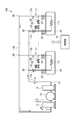
- FIG. 1 is a schematic diagram showing a cooling system according to an embodiment of the present invention.
- the cooling system 100 according to the present embodiment has a plurality of film forming units mounted on a multi-chamber type film forming apparatus that performs a film forming process on a substrate. N 2 gas).
- the cooling system 100 includes a main circulation line 11, a compressor 12 provided in the circulation line 11, front and rear coolers 13 and 14 provided before and after the compressor 12 in the circulation line 11, and N in the circulation line 11. a gas supply line 15 for supplying 2 gas, a gas discharge line 16 for discharging the N 2 gas from the circulation line 11, provided corresponding to the plurality of film deposition unit 21, each connected to a circulation line 11 in parallel A cooling line 17, a bypass line 18 that bypasses the object to be cooled, and a control unit 19.
- N 2 gas which is a gaseous cooling medium is circulated.
- the circulation line 11 includes a front half part 11a on the downstream side of the rear-stage cooler 14 having a supply port 28 for supplying N 2 gas to each film forming unit 21, and an exhaust port through which the N 2 gas is discharged from each film forming unit 21. 29 and the latter half part 11b.
- the compressor 12 is for increasing the pressure of the N 2 gas in the circulation line 11 and circulating it in the circulation line 11.
- the pre-cooler 13 is for cooling the N 2 gas whose temperature has been increased by heat exchange in each film forming processing unit 21, and that the high-temperature N 2 gas is introduced into the compressor 12. It has a function to prevent.
- the rear-stage cooler 14 cools the N 2 gas compressed by the compressor 12 to a predetermined temperature, and adjusts the N 2 gas supplied to each film forming unit 21 to a predetermined temperature. It has a function.
- the front-stage cooler 13 and the rear-stage cooler 14 incorporate a bent pipe through which a cooling medium such as cooling water flows, and the supplied N 2 gas is cooled by the cooling medium.
- the cooling line 17 corresponding to each film forming unit 21 is connected to the circulation line 11.
- the cooling line 17 includes a supply unit 17 a that supplies N 2 gas from a supply port 28 of the front stage unit 11 a of the circulation line 11 to a substrate mounting table (described later) in the film forming unit 21.
- the supply portion 17a is provided with a needle valve 22 and an opening / closing valve 23 for adjusting the flow rate in order from the supply port 28 side.
- the discharge portion 17b is provided with an opening / closing valve 24.
- the bypass line 18 is provided so as to connect the supply unit 17a and the discharge unit 17b of the cooling line 17 and is provided so as to bypass the substrate mounting table to be cooled.
- the bypass line 18 is provided with an open / close valve 25 and a needle valve 26 for adjusting the flow rate in order from the supply part 17a side of the cooling line 17.
- the bypass line 18 is not used when the substrate mounting table is cooled in the corresponding film forming processing unit 21, and is used when the substrate forming table is not cooled in the corresponding film forming processing unit 21. That is, when the substrate deposition table is cooled by the corresponding film formation processing unit 21, the opening / closing valves 23 and 24 are opened, the opening / closing valve 25 is closed, and the N 2 gas flows into the gas flow path 17c. If the substrate mounting table is not cooled in the corresponding film formation processing unit, the open / close valves 23 and 24 are closed, the open / close valve 25 is opened, and N 2 gas flows through the bypass line 18.
- the flow rate of the bypass line 18 is adjusted by the needle valve 26, and the conductance when flowing through the bypass line 18 can be matched with the conductance when flowing through the gas flow path 17c in the substrate mounting table.
- the conductance may be controlled based on the flow rate of N 2 gas measured by a flow meter and based on the measured value, or based on the rotational speed of the compressor 12.
- a conductance valve (not shown) may be provided in the circulation line 11.
- the control unit 19 includes a computer (microprocessor), and controls each component, for example, the compressor 12, the front cooler 13, the rear cooler 14, the needle valves 22, 26, the open / close valves 23, 24, 25, and the like. It has become.
- the control unit 19 is configured to execute a predetermined processing recipe based on a command from an overall control unit (not shown) of the multi-chamber type film forming apparatus, and stores control parameters and recipes necessary for that purpose.
- a storage unit, input means, and a display are provided.
- the multi-chamber type film forming apparatus has a common transfer chamber (not shown) having a polygonal shape, and a plurality of film forming units 21 are connected to the transfer chamber via gate valves (not shown). It is connected. Then, while the transfer chamber is kept in a vacuum state, a transfer device (not shown) provided therein can carry the substrate into and out of each film forming unit 21 with the gate valve opened. It has become.
- a transfer device not shown
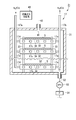
- FIG. 2 is a cross-sectional view showing an example of a film forming unit.
- the film formation processing unit 21 performs a film formation process on a plurality of substrates at a time, and includes a chamber 31 that accommodates the plurality of substrates.
- the chamber 31 has a plurality of substrate mounting tables 32 on which the substrates S are mounted. These substrate mounting tables 32 are arranged at predetermined intervals along the vertical direction.
- the substrate mounting table 32 is supported by the chamber 31 by a support member 33.
- the substrate mounting table 32 has a rectangular shape corresponding to the substrate S in plan view. Inside the substrate mounting table 32, the above-described gas flow path 17 c of the cooling line 17 for cooling the substrate mounting table 32 and a heater 34 for heating the substrate mounting table 32 are provided.
- the supply unit 17a and the discharge unit 17b of the cooling line 17 are vertically inserted into the chamber 31 from above, and are provided so as to face each other with the plurality of substrate mounting tables 32 interposed therebetween.
- a supply side connection pipe 17d and a discharge side connection pipe 17e connected to the gas flow path 17c of each substrate mounting table 32 extend from the supply part 17a and the discharge part 17b, respectively.
- the heater 34 is supplied with power from a heater power source (not shown) and generates heat. Power supply to the heater power supply is controlled by a heater control unit (not shown).
- control unit 19 of the cooling system 100 controls the flow rate of N 2 gas, and the heater control unit controls the output of the heater power supply. By doing so, the temperature of the substrate mounting table 32 is controlled.
- a gas inlet 41 is formed in the top wall of the chamber 31, and a gas supply pipe 42 is connected to the gas inlet 41.
- a film forming gas used for film formation is supplied from the film forming gas supply system 43 to the gas supply pipe 42, and the film forming gas is introduced into the chamber 31 through the gas inlet 41.
- the film forming gas include a source gas containing a material of a film to be formed, a reaction gas that reacts with the source gas, and the like.
- An exhaust port 51 for exhausting the inside of the chamber 31 is provided on the bottom side of the chamber 31, and an exhaust pipe 52 is connected to the exhaust port 51.
- the exhaust pipe 52 is provided with an automatic pressure control valve (APC) 53 and a vacuum pump 54.
- the vacuum pump 54 evacuates the chamber 31 while controlling the pressure in the chamber 31 by the automatic pressure control valve (APC) 53. Then, the inside is made a predetermined degree of vacuum.
- a film forming gas for example, source gas and reaction gas
- a film forming gas supply system 43 supplies from the film forming gas supply system 43 to the chamber 31 through the gas supply pipe 42 and the gas inlet 41.
- a predetermined film is formed on the substrate S by CVD (Chemical Vapor Deposition) while the substrate S is brought to a predetermined temperature by the temperature-controlled substrate mounting table 32.
- the film forming gas may be converted into plasma by an appropriate plasma generating means and the film forming process may be performed by plasma CVD.
- the temperature and flow rate of the N 2 gas supplied as a cooling medium from the cooling system 100 are controlled, and the current supplied to the heater 34 is controlled.
- the temperature of the substrate mounting table 32 is controlled to set the temperature of the substrate S thereon to a predetermined temperature, and an appropriate film forming gas is introduced into the chamber 31 from the film forming gas supply system 43 to form a predetermined film on the substrate S. Is deposited.
- the temperature of the N 2 gas supplied to the substrate mounting table 32 is set to 30 to 50 ° C., and the temperature of the substrate mounting table 32 is controlled to 150 to 200 ° C.
- the compressor 12 circulates the N 2 gas, which is a cooling medium, in the main circulation line 11 at a predetermined flow rate, and the N 2 gas that has been compressed by the compressor 12 and whose temperature has increased is a subsequent cooler 14.
- N 2 gas cooled to a predetermined temperature from the supply port 28 of the front half portion 11a of the circulation line 11, incorporated into cooling line 17 corresponding to the plurality of film deposition unit 21, N 2 gas after being subjected to cooling Is discharged from the cooling line 17 through the discharge port 29 to the second half part 11 b of the circulation line 11.
- N 2 gas cooled to a predetermined temperature is supplied from the supply port 28 of the first half part 11a to the supply part 17a of the cooling line 17, and each film is formed through the supply side connection pipe 17d (FIG. 2).
- the gas flows through the gas flow paths 17 c formed in the plurality of substrate platforms 32 of the processing unit 21, and each substrate platform 32 is cooled.
- the temperature of the N 2 gas flowing through the gas flow path 17c of the substrate mounting table 32 is raised, the N 2 gas temperature rises, reaches the discharge section 17b through the discharge side connecting pipe 17e, the discharge portion It is discharged from 17 b through the discharge port 29 to the second half 11 b of the circulation line 11.
- the N 2 gas that has flowed through the second half 11 b returns to the compressor 12.
- the compressor 12 since the N 2 gas whose temperature has increased flows in the second half 11 b of the circulation line 11, if it returns directly to the compressor 12, the compressor 12 may be adversely affected. Therefore, the N 2 gas whose temperature has risen is cooled by the front cooler 13 provided in the front stage of the compressor 12 and then supplied to the compressor 12. However, if the temperature of the N 2 gas supplied to the compressor 12 is an allowable temperature in the compressor 12, it is not necessary to provide the pre-cooler 13.
- the cooling system 100 having the main circulation line 11 is provided corresponding to one multi-chamber type film forming apparatus, and the circulation line 11 is filled with a gaseous cooling medium.
- a certain N 2 gas is circulated by the compressor 12, and the temperature of the N 2 gas is cooled to a predetermined temperature by a rear cooler 14 provided at the rear stage of the compressor 12, and then the cooled N 2 gas is supplied to each film forming processing unit. 21 to the substrate mounting table 32.
- N 2 gas which is a gaseous cooling medium.
- N 2 gas is supplied as a cooling medium from a batch supply line of factory equipment or the like, if the flow rate of N 2 gas decreases by 10% due to the influence of operating conditions of other apparatuses, the film forming processing unit The cooling capacity at 21 is reduced by 10%, and the temperature of the substrate mounting table 32 cannot be maintained at a desired temperature.
- the N 2 gas is stably supplied without such fluctuation. can do.
- the cooling lines 17 that supply N 2 gas to the plurality of film forming units 21 are respectively connected in parallel to the circulation line 11, the substrate mounting table 32 that is the cooling target of each film forming unit 21 is provided. N 2 gas having substantially the same temperature can be supplied, and the temperature of the substrate mounting tables 32 of the plurality of film forming units 21 can be cooled uniformly. Further, by providing the bypass line 18 and operating the on-off valves 23, 24, and 25, the N 2 gas can be caused to flow to the bypass line 18 in the film forming unit 21 that does not require cooling. Based on the processing recipe, the presence or absence of cooling of the substrate platform 23 in the plurality of film forming units 21 can be switched for each processing step.
- the flow rate is adjusted by the needle valve 26 for flow rate control, and the conductance when flowing through the bypass line 18 is matched with the conductance when flowing through the cooling line 17 (gas flow path 17c in the substrate mounting table).
- the bypass line is not used, if the number of film forming units that supply N 2 gas, which is a cooling medium, fluctuates, the cooling capacity fluctuates and the rotation speed of the compressor fluctuates. In order to achieve this, a buffer tank is required, but by providing such a bypass line, the buffer tank becomes unnecessary.
- the cooling medium is used.
- a certain N 2 gas is supplied to four film forming units 21, and the cooling capacity per one film forming unit varies by 1.25 times.
- bypass line 18 is provided, and the needle valve 26 bypasses the bypass line 18 so that the conductance when the N 2 gas flows through the bypass line 18 is equal to the conductance when the N 2 gas flows through the gas flow path 17c.
- the load fluctuation can be reduced by adjusting the flow rate. For this reason, even when N 2 gas as a cooling medium is not supplied to some of the film forming units 21, stable operation can be ensured without using a buffer tank, and fluctuations in cooling capacity occur. Absent.
- the present invention is not limited to the above embodiment and can be variously modified.
- the cooling line 17 ( Alternatively, the bypass line 18) may be configured to constitute a part of the circulation line 11.
- the cooling system of the present invention is applied to the multi-chamber type film forming apparatus.
- the present invention is not limited to this, and dry etching can be used as long as a gaseous cooling medium can be used for cooling the substrate mounting table.
- the present invention can be applied to other substrate processing apparatuses such as an apparatus.
- the film processing unit illustrated as one that processes a plurality of substrates at once a single wafer type may be used.
- the present invention is not limited to the substrate processing apparatus, and can be applied to any apparatus having a cooling target that can be cooled by a gaseous cooling medium.
- the number of cooling targets may be one.
- an example of using the N 2 gas as a gaseous cooling medium it is also possible to use another gas such as Ar gas.
- the cooler was provided in the front
Landscapes
- Cooling Or The Like Of Electrical Apparatus (AREA)
- Container, Conveyance, Adherence, Positioning, Of Wafer (AREA)
- Chemical Vapour Deposition (AREA)
Abstract
冷却対象を有する装置において、冷却対象を気体状の冷却媒体により冷却する冷却システム(100)は、気体状の冷却媒体が循環する循環ライン(11)と、循環ライン(11)に接続され、冷却対象に冷却媒体を供給する冷却ライン(17)と、循環ライン(11)に設けられ、冷却媒体を圧縮し循環させるコンプレッサ(12)と、循環ライン(11)に設けられ、冷却ライン(17)に供給される冷却媒体を所定温度に冷却する冷却機構(14)とを具備する。
Description
本発明は、冷却対象を有する装置おいて、冷却対象を気体状の冷却媒体により冷却する冷却システムおよび冷却方法、ならびに冷却システムを用いた基板処理装置に関する。
FPDや太陽電池等の基板の製造過程においては、所定の膜を成膜する成膜処理やドライエッチング処理が存在する。このような成膜処理やドライエッチング処理を行う場合、基板が所定の温度になるように温度制御を行う必要があり、そのために基板載置台にヒーターおよび冷却媒体流路を設けてヒーターによる加熱および冷却媒体による冷却により基板の温度制御を行っている(例えば特許文献1)。
冷却のための冷却媒体としては液体状のものおよび気体状のものを用いることができるが、気体状の冷却媒体を用いる場合には、通常、工場設備等の一括供給ラインからの窒素ガスを使用する。
一方、このような成膜処理やドライエッチング処理を効率的に行うための装置として、複数の処理部(処理チャンバ)を備えたマルチチャンバ型処理装置が知られている(例えば特許文献2)。このようなマルチチャンバ型処理装置では、処理チャンバごとに、基板載置台の温度制御を行っており、気体状の冷却媒体として工場設備等の一括供給ラインからの窒素ガスを使用する場合には、一括供給ラインから各処理チャンバに窒素ガスが供給される。
しかし、気体状の冷却媒体として工場設備等の一括供給ラインの窒素ガスを使用する場合、他の装置の使用状況などにより流量が変動し、安定した冷却能力を得ることが困難である。また、コンプレッサ等で気体冷媒を循環させる場合、装置側の使用状況の変化により負荷変動が起きると、運転状態が不安定になり供給能力が変動してしまうおそれがある。これを解消するためには、設備側に大型のバッファタンクを設けることが有効であるが、バッファタンクを設けると、設備負担が大きくなってしまう。また、バッファタンクを設置するスペースを確保できない工場では、供給能力の変動を解消することが困難である。
本発明の課題は、冷却能力が安定し、かつ大型のバッファタンクを設けることなく気体状の冷却媒体を安定して供給することができる冷却システムおよび冷却方法、ならびにそのような冷却システムを用いた基板処理装置を提供することにある。
すなわち、本発明の第1の観点によれば、冷却対象を有する装置において、冷却対象を気体状の冷却媒体により冷却する冷却システムであって、気体状の冷却媒体が循環する循環ラインと、前記循環ラインに接続され、前記冷却対象に前記冷却媒体を供給する冷却ラインと、前記循環ラインに設けられ、前記冷却媒体を圧縮し循環させるコンプレッサと、前記循環ラインに設けられ、前記冷却ラインに供給される前記冷却媒体を所定温度に冷却する冷却機構とを具備する、冷却システムが提供される。
上記第1の観点において、前記冷却ラインに接続され、前記冷却対象をバイパスするバイパスラインと、前記冷却媒体の流路を前記冷却対象と前記バイパスラインとで切り替える切替機構とを具備してもよい。この場合に、前記バイパスラインの前記冷却媒体の流量を調節して前記バイパスラインのコンダクタンスを前記冷却対象のコンダクタンスに合わせる流量調節機構を具備してもよい。
前記冷却機構は、前記コンプレッサの後段に設けられた後段クーラーを有する構成とすることができ、また、前記冷却機構は、前記コンプレッサの前段に設けられた前段クーラーを有する構成であってもよい。また、前記冷却媒体としては窒素ガスを用いることができる。
本発明の第2の観点によれば、冷却対象を有する装置において、冷却対象を気体状の冷却媒体により冷却する冷却方法であって、前記冷却対象に前記冷却媒体を供給する冷却ラインを循環ラインに設けることと、コンプレッサにより前記循環ライン内に気体状の冷却媒体を循環させることと、冷却機構により前記循環ライン内を循環する冷却媒体を所定の温度に冷却することと、前記冷却機構で冷却された冷却媒体を前記冷却ラインに流して、前記冷却対象に供給することにより前記冷却対象を冷却することとを含む、冷却方法が提供される。
上記第1の観点および第2の観点において、前記冷却対象および前記冷却ラインを複数有し、複数の前記冷却ラインは、各々並列に前記循環ラインに接続されていることが好ましい。また、前記冷却対象として、マルチチャンバ型基板処理装置の基板処理部にそれぞれ設けられた基板載置台を適用することができる。
上記第2の観点において、前記冷却対象をバイパスするバイパスラインを前記冷却ラインに接続して設け、冷却を行わない冷却対象について、切替機構により冷却媒体の流路を前記バイパスラインに切り替えるようにしてもよい。この場合、前記バイパスラインに前記冷却媒体を流す際に、前記バイパスラインのコンダクタンスを前記冷却対象のコンダクタンスに合わせるように、前記バイパスラインにおける前記冷却媒体の流量を調節してもよい。
本発明の第3の観点によれば、複数の基板処理部を有し、前記基板処理部により所定の基板処理を行う基板処理装置であって、各基板処理部は、基板を載置する基板載置台と、前記基板載置台に載置された基板に対して所定の処理を行う処理機構とを有し、前記基板処理装置は、前記複数の基板処理部の各基板載置台に気体状の冷却媒体を供給して冷却する冷却システムを具備し、前記冷却システムは、前記冷却媒体が循環する循環ラインと、前記循環ラインに接続され、複数の前記基板処理部の前記基板載置台にそれぞれ前記冷却媒体を供給する複数の冷却ラインと、前記循環ラインに設けられ、前記冷却媒体を圧縮し循環させるコンプレッサと、前記循環ラインに設けられ、前記冷却ラインに供給される前記冷却媒体を所定温度に冷却する冷却機構とを有する基板処理装置を提供される。
本発明においては、メインの循環ラインを設け、この循環ラインにコンプレッサにより気体状の冷却媒体を循環させ、冷却機構により冷却媒体を所定の温度に冷却し、冷却された冷却媒体を循環ラインに設けられた冷却ラインに流して冷却対象に供給し、冷却対象を冷却する。これにより、従来のように、他の装置の使用状況により気体状の冷却媒体の流量不足が生じるおそれがなく、設備側に大型のバッファタンクを設けなくても、安定して気体状の冷却媒体を供給することができる。
以下、添付図面を参照して本発明の実施形態について説明する。
図1は、本発明の一実施形態に係る冷却システムを示す模式図である。
本実施形態の冷却システム100は、基板に対して成膜処理を行うマルチチャンバ型成膜処理装置に搭載された複数の成膜処理部に、個別的に気体状の冷却媒体である窒素ガス(N2ガス)を供給するものである。
図1は、本発明の一実施形態に係る冷却システムを示す模式図である。
本実施形態の冷却システム100は、基板に対して成膜処理を行うマルチチャンバ型成膜処理装置に搭載された複数の成膜処理部に、個別的に気体状の冷却媒体である窒素ガス(N2ガス)を供給するものである。
この冷却システム100は、メインの循環ライン11と、循環ライン11に設けられたコンプレッサ12と、循環ライン11におけるコンプレッサ12の前後に設けられた前段クーラー13および後段クーラー14と、循環ライン11にN2ガスを供給するガス供給ライン15と、循環ライン11からN2ガスを排出するガス排出ライン16と、複数の成膜処理部21に対応して設けられ、各々並列に循環ライン11に接続された冷却ライン17と、冷却対象をバイパスするバイパスライン18と、制御部19とを有する。
メインの循環ライン11は、気体状の冷却媒体であるN2ガスが循環される。循環ライン11は、各成膜処理部21にN2ガスを供給する供給口28を有する後段クーラー14下流側の前半部11aと、各成膜処理部21からN2ガスが排出される排出口29を有する後半部11bとを有している。
コンプレッサ12は循環ライン11のN2ガスを昇圧して循環ライン11中を循環させるためのものである。また、前段クーラー13は、各成膜処理部21内で熱交換することにより温度が上昇したN2ガスを冷却するためのものであり、コンプレッサ12に高温のN2ガスが導入されることを防止する機能を有している。また、後段クーラー14は、コンプレッサ12により圧縮されて温度が上昇したN2ガスを所定温度に冷却するものであり、各成膜処理部21に供給されるN2ガスを所定の温度に調整する機能を有する。前段クーラー13および後段クーラー14は、冷却水等の冷却媒体が流れる屈曲したパイプを内蔵しており、供給されたN2ガスが冷却媒体により冷却される。
各成膜処理部21に対応する冷却ライン17は循環ライン11に接続されている。具体的には、冷却ライン17は、循環ライン11の前段部11aの供給口28から成膜処理部21内の冷却対象である基板載置台(後述)にN2ガスを供給する供給部17aと、その基板載置台から循環ライン11の後段部11bの排出口29へN2ガスを排出する排出部17bと、基板載置台内のガス流路17cとを有する。供給部17aには供給口28側から順に流量調節のためのニードルバルブ22と開閉バルブ23が設けられている。また排出部17bには開閉バルブ24が設けられている。
バイパスライン18は、冷却ライン17の供給部17aと排出部17bとを繋ぐように設けられ、冷却対象である基板載置台をバイパスするように設けられている。バイパスライン18には、冷却ライン17の供給部17a側から順に開閉バルブ25と流量調節のためのニードルバルブ26とが設けられている。
バイパスライン18は、対応する成膜処理部21において基板載置台の冷却を行う場合には使用されず、対応する成膜処理部21で基板載置台の冷却を行わない場合に使用される。すなわち、対応する成膜処理部21で基板載置台の冷却を行う場合には、開閉バルブ23および24を開成し、開閉バルブ25を閉成してN2ガスがガス流路17cに流れるようにされ、対応する成膜処理部で基板載置台の冷却を行わない場合には、開閉バルブ23および24を閉成し、開閉バルブ25を開成してバイパスライン18にN2ガスが流れるようにされる。このとき、ニードルバルブ26によりバイパスライン18の流量を調節し、バイパスライン18を流れた場合のコンダクタンスを、基板載置台内のガス流路17cを流れた場合のコンダクタンスに合わせることができるようになっている。コンダクタンスの制御は、流量計によりN2ガスの流量を測定し、その値に基づいて行ってもよいし、コンプレッサ12の回転数に基づいて行ってもよい。
なお、循環ライン11に不図示のコンダクタンスバルブを設けてもよい。
制御部19は、コンピュータ(マイクロプロセッサ)を備えており、各構成部、例えば、コンプレッサ12、前段クーラー13、後段クーラー14、ニードルバルブ22,26、開閉バルブ23,24,25等を制御するようになっている。制御部19は、マルチチャンバ型成膜処理装置の全体制御部(図示せず)の指令に基づいて所定の処理レシピを実行するようになっており、そのために必要な制御パラメータやレシピを記憶した記憶部や、入力手段およびディスプレイを備えている。
マルチチャンバ型成膜処理装置は、多角形をなす共通の搬送室(図示せず)を有しており、複数の成膜処理部21は、ゲートバルブ(図示せず)を介して搬送室に接続されている。そして、搬送室を真空状態に保ったまま、その中に設けられた搬送装置(図示せず)により、ゲートバルブを開放した状態で各成膜処理部21に対する基板の搬入および搬出が行えるようになっている。基板には特に制限はないが、フラットパネルディスプレイ(FPD)基板や太陽電池用基板等の矩形基板が例示される。
次に、成膜処理部21の具体的な構成例について説明する。
図2は成膜処理部の一例を示す断面図である。成膜処理部21は、複数の基板に対して一括して成膜処理を行うものであり、複数の基板を収容するチャンバ31を有している。チャンバ31内には、それぞれ基板Sを載置する複数の基板載置台32を有している。これら基板載置台32は、鉛直方向に沿って所定の間隔をおいて配置されている。基板載置台32は支持部材33によりチャンバ31に支持されている。
図2は成膜処理部の一例を示す断面図である。成膜処理部21は、複数の基板に対して一括して成膜処理を行うものであり、複数の基板を収容するチャンバ31を有している。チャンバ31内には、それぞれ基板Sを載置する複数の基板載置台32を有している。これら基板載置台32は、鉛直方向に沿って所定の間隔をおいて配置されている。基板載置台32は支持部材33によりチャンバ31に支持されている。
基板載置台32は、平面形状が基板Sに対応する矩形状をなしている。基板載置台32の内部には、基板載置台32を冷却するための上述した冷却ライン17のガス流路17cと、基板載置台32を加熱するためのヒーター34が設けられている。
冷却ライン17の供給部17aおよび排出部17bは、上方からチャンバ31内に垂直に挿入されており、複数の基板載置台32を挟んで対向するように設けられている。供給部17aおよび排出部17bからは、それぞれ各基板載置台32のガス流路17cに接続される供給側接続配管17dおよび排出側接続配管17eが延びている。
ヒーター34はヒーター電源(図示せず)から給電されて発熱するようになっている。ヒーター電源への給電はヒーター制御部(図示せず)により制御される。
そして、上述したマルチチャンバ型成膜処理装置の全体制御部からの指令に基づいて、冷却システム100の制御部19によりN2ガスの流量を制御するとともに、ヒーター制御部によりヒーター電源の出力を制御することによって、基板載置台32の温度が制御される。
チャンバ31の天壁にはガス導入口41が形成されており、ガス導入口41にはガス供給配管42が接続されている。このガス供給配管42には、成膜ガス供給系43から成膜のために用いられる成膜ガスが供給され、成膜ガスはガス導入口41を経てチャンバ31内に導入される。成膜ガスとしては、成膜しようとする膜の材料を含む原料ガス、原料ガスと反応する反応ガス等を挙げることができる。
チャンバ31の底側にはチャンバ31内を排気するための排気口51が設けられており、この排気口51には排気配管52が接続されている。排気配管52には自動圧力制御バルブ(APC)53と真空ポンプ54が設けられており、自動圧力制御バルブ(APC)53によりチャンバ31内の圧力を制御しつつ真空ポンプ54によりチャンバ31内を排気して、その中が所定の真空度にされる。
そして、チャンバ31内を所定の真空度にした状態で、成膜ガス供給系43からガス供給配管42およびガス導入口41を経て、チャンバ31内に成膜ガス(例えば原料ガスおよび反応ガス)を導入して、温度制御されている基板載置台32によって基板Sを所定温度にしつつ、基板S上にCVD(Chemical Vapor Deposition)により所定の膜を成膜する。この際に、適宜のプラズマ生成手段により成膜ガスをプラズマ化してプラズマCVDで成膜処理を行ってもよい。
以上のような成膜処理部21で成膜処理を行う場合には、冷却システム100から冷却媒体として供給されるN2ガスの温度と流量を制御するとともに、ヒーター34へ供給する電流を制御して、基板載置台32の温度制御を行いその上の基板Sの温度を所定温度にし、成膜ガス供給系43から適宜の成膜ガスをチャンバ31内に導入して基板S上に所定の膜を成膜する。例えば、基板載置台32に供給されるN2ガスの温度を30~50℃とし、基板載置台32の温度を150~200℃に制御する。
このとき、冷却システム100においては、コンプレッサ12により冷却媒体であるN2ガスを所定流量でメインの循環ライン11内で循環させ、コンプレッサ12により圧縮されて温度が上昇したN2ガスを後段クーラー14によって所定温度に冷却する。所定温度に冷却されたN2ガスは循環ライン11の前半部11aの供給口28から、複数の成膜処理部21に対応する冷却ライン17に取り入れられ、冷却に供された後のN2ガスは冷却ライン17から排出口29を経て循環ライン11の後半部11bに排出される。具体的には、前半部11aの供給口28から、所定温度に冷却されたN2ガスが、冷却ライン17の供給部17aに供給され、供給側接続配管17d(図2)を経て各成膜処理部21の複数の基板載置台32内に形成されたガス流路17cに流れ、各基板載置台32を冷却する。これにより、各基板載置台32内のガス流路17cを流れたN2ガスの温度は上昇し、温度が上昇したN2ガスは、排出側接続配管17eを経て排出部17bに至り、排出部17bから排出口29を経て循環ライン11の後半部11bに排出される。そして、後半部11bを流れたN2ガスはコンプレッサ12に戻る。
このとき、循環ライン11の後半部11bには温度が上昇したN2ガスが流れるので、それが直接コンプレッサ12に戻るとコンプレッサ12に悪影響を及ぼすおそれがある。そのため、コンプレッサ12の前段に設けられた前段クーラー13により温度が上昇したN2ガスを冷却してからコンプレッサ12に供給する。ただし、コンプレッサ12に供給されるN2ガスの温度がコンプレッサ12において許容される温度であれば、前段クーラー13は設ける必要はない。
循環ライン11内を流れるN2ガスを入れ替える場合は、ガス排出ライン16からN2ガスを排出した後、ガス供給ライン15から新しいN2ガスを供給する。また、N2ガスの入れ替え以外でも、循環ライン11から僅かにN2ガスがリークした場合等には、ガス供給ライン15から循環ライン11にN2ガスを補充することができる。
以上のように、本実施形態によれば、メインの循環ライン11を有する冷却システム100を、一つのマルチチャンバ型成膜処理装置に対応して設け、この循環ライン11に気体状の冷却媒体であるN2ガスをコンプレッサ12により循環させるとともに、コンプレッサ12の後段に設けられた後段クーラー14によりN2ガスの温度を所定温度に冷却した後に、その冷却されたN2ガスを各成膜処理部21の基板載置台32に供給する。このため、従来のように、工場設備等の一括供給ラインの窒素ガスを使用する場合とは異なり、他の装置の使用状況により窒素ガスの流量不足が生じるおそれがなく、設備側に大型のバッファタンクを設けなくても、安定して気体状の冷却媒体であるN2ガスを供給することができる。例えば工場設備等の一括供給ラインから冷却媒体としてN2ガスの供給を受ける場合、他の装置の運転状況の影響を受けてN2ガスの流量が10%低下してしまうと、成膜処理部21での冷却能力が10%低下し、基板載置台32の温度を所望の温度に保つことができなくなるが、本実施形態の場合にはそのような変動がなく安定してN2ガスを供給することができる。
また、複数の成膜処理部21にそれぞれN2ガスを供給する冷却ライン17を各々並列に循環ライン11に接続しているため、各成膜処理部21の冷却対象である基板載置台32にほぼ同じ温度のN2ガスを供給することができ、複数の成膜処理部21の基板載置台32を温度を均一に冷却することができる。また、バイパスライン18を設け、開閉バルブ23,24,25を操作することにより、冷却が必要のない成膜処理部21においてはN2ガスをバイパスライン18に流すことができ、制御部19によって処理レシピに基づいて、処理ステップごとに複数の成膜処理部21における基板載置台23の冷却の有無を切り替えることができる。このとき、流量制御用のニードルバルブ26により流量調節して、バイパスライン18を流れた場合のコンダクタンスを、冷却ライン17(基板載置台内のガス流路17c)を流れた場合のコンダクタンスに合わせることにより、N2ガスを供給している他の成膜処理部21への影響を最小限に抑えることができる。バイパスラインを用いない場合には、冷却媒体であるN2ガスを供給する成膜処理部の数が変動した場合、冷却能力が変動したり、コンプレッサの回転数が変動したりし、これらを抑制するためにはバッファタンクが必要であるが、このようなバイパスラインを設けることによりバッファタンクが不要となる。
例えば、マルチチャンバ型成膜処理装置が5台の成膜処理部21を有する構成の場合、バイパスラインを用いずに一つの成膜処理部21に対応する冷却ライン17を閉じると、冷却媒体であるN2ガスを4台の成膜処理部21に供給することになり、成膜処理部1台当たりの冷却能力が1.25倍に変動してしまう。また、このような負荷変動によりコンプレッサ12の運転が不安定になって回転数が変動する場合があり、例えば10%変動した場合、それにともなってN2ガスの流量(=冷却能力)も変動してしまう。これに対して、バイパスライン18を設け、N2ガスがバイパスライン18を流れた際のコンダクタンスが、ガス流路17cを流れた際のコンダクタンスと同等となるように、ニードルバルブ26によりバイパスライン18の流量を調節することにより、負荷変動を小さくすることができる。このため、一部の成膜処理部21に冷却媒体であるN2ガスを供給しない場合であっても、バッファタンクを用いることなく安定した運転を確保することができ、冷却能力の変動は生じない。
なお、本発明は上記実施形態に限定されることなく種々変形可能である。例えば、上記実施形態では、全ての冷却ライン17を各々並列に循環ライン11に接続した例を示したが、例えば、図3に示すように、最後段の成膜処理部21の冷却ライン17(またはバイパスライン18)が、循環ライン11の一部を構成するように構成してもよい。
また、上記実施形態では、本発明の冷却システムをマルチチャンバ型成膜処理装置に適用したが、これに限らず、基板載置台の冷却に気体状の冷却媒体を使用可能であれば、ドライエッチング装置等の他の基板処理装置に適用することができる。また、成膜処理部として複数の基板を一括して処理するものを例示したが、枚葉式のものであってもよい。さらに、基板処理装置に限らず、気体状の冷却媒体により冷却可能な冷却対象を有する装置であれば適用可能である。
また、上記実施形態では、冷却対象である成膜処理部を複数設けた場合について示したが、冷却対象は一つであってもよい。また、上記実施形態では、気体状の冷却媒体としてN2ガスを用いた例を示したが、Arガス等の他のガスを用いることもできる。さらに、上記実施形態では、コンプレッサの前段および後段にクーラーを設けたが、冷却対象に所望の温度の冷却媒体を供給できればこれに限るものではない。
11;循環ライン、11a;前半部、11b;後半部、12;コンプレッサ、13;前段クーラー、14;後段クーラー、15;ガス供給ライン、16;ガス排出ライン、17;冷却ライン、17a;供給部、17b;排出部、17c;ガス流路、18;バイパスライン、19;制御部、21;成膜処理部、22,26;ニードルバルブ、23,24,25;開閉バルブ、28;供給口、29;排出口、100;冷却システム
Claims (20)
- 冷却対象を有する装置において、冷却対象を気体状の冷却媒体により冷却する冷却システムであって、
気体状の冷却媒体が循環する循環ラインと、
前記循環ラインに接続され、前記冷却対象に前記冷却媒体を供給する冷却ラインと、
前記循環ラインに設けられ、前記冷却媒体を圧縮し循環させるコンプレッサと、
前記循環ラインに設けられ、前記冷却ラインに供給される前記冷却媒体を所定温度に冷却する冷却機構と
を具備する、冷却システム。 - 前記冷却対象および前記冷却ラインを複数有し、複数の前記冷却ラインは、各々並列に前記循環ラインに接続されている、請求項1に記載の冷却システム。
- 前記冷却対象は、マルチチャンバ型基板処理装置の基板処理部にそれぞれ設けられた基板載置台である、請求項1に記載の冷却システム。
- 前記冷却ラインに接続され、前記冷却対象をバイパスするバイパスラインと、前記冷却媒体の流路を前記冷却対象と前記バイパスラインとで切り替える切替機構とを具備する、請求項1に記載の冷却システム。
- 前記バイパスラインの前記冷却媒体の流量を調節して前記バイパスラインのコンダクタンスを前記冷却対象のコンダクタンスに合わせる流量調節機構を具備する、請求項4に記載の冷却システム。
- 前記冷却機構は、前記コンプレッサの後段に設けられた後段クーラーを有する、請求項1に記載の冷却システム。
- 前記冷却機構は、前記コンプレッサの前段に設けられた前段クーラーを有する、請求項6に記載の冷却システム。
- 前記冷却媒体は窒素ガスである、請求項1に記載の冷却システム。
- 冷却対象を有する装置において、冷却対象を気体状の冷却媒体により冷却する冷却方法であって、
前記冷却対象に前記冷却媒体を供給する冷却ラインを循環ラインに設けることと、
コンプレッサにより前記循環ライン内に気体状の冷却媒体を循環させることと、
冷却機構により前記循環ライン内を循環する冷却媒体を所定の温度に冷却することと、
前記冷却機構で冷却された冷却媒体を前記冷却ラインに流して、前記冷却対象に供給することにより前記冷却対象を冷却することと
を含む、冷却方法。 - 前記冷却対象および前記冷却ラインを複数有し、複数の前記冷却ラインは、各々並列に前記循環ラインに接続されている、請求項9に記載の冷却方法。
- 前記冷却対象は、マルチチャンバ型基板処理装置の基板処理部にそれぞれ設けられた基板載置台である、請求項9に記載の冷却方法。
- 前記冷却対象をバイパスするバイパスラインを前記冷却ラインに接続して設け、冷却を行わない冷却対象について、切替機構により冷却媒体の流路を前記バイパスラインに切り替える、請求項9に記載の冷却方法。
- 前記バイパスラインに前記冷却媒体を流す際に、前記バイパスラインのコンダクタンスを前記冷却対象のコンダクタンスに合わせるように、前記バイパスラインにおける前記冷却媒体の流量を調節する、請求項12に記載の冷却方法。
- 複数の基板処理部を有し、前記基板処理部により所定の基板処理を行う基板処理装置であって、
各基板処理部は、基板を載置する基板載置台と、前記基板載置台に載置された基板に対して所定の処理を行う処理機構とを有し、
前記基板処理装置は、前記複数の基板処理部の各基板載置台に気体状の冷却媒体を供給して冷却する冷却システムを具備し、
前記冷却システムは、
前記冷却媒体が循環する循環ラインと、
前記循環ラインに接続され、複数の前記基板処理部の前記基板載置台にそれぞれ前記冷却媒体を供給する複数の冷却ラインと、
前記循環ラインに設けられ、前記冷却媒体を圧縮し循環させるコンプレッサと、
前記循環ラインに設けられ、前記冷却ラインに供給される前記冷却媒体を所定温度に冷却する冷却機構と
を有する、基板処理装置。 - 複数の前記冷却ラインは、各々並列に前記循環ラインに接続されている、請求項14に記載の基板処理装置。
- 前記冷却ラインに接続され、前記基板載置台をバイパスするバイパスラインと、前記冷却媒体の流路を前記基板載置台と前記バイパスラインとで切り替える切替機構とを具備する、請求項14に記載の基板処理装置。
- 前記バイパスラインの前記冷却媒体の流量を調節して前記バイパスラインのコンダクタンスを前記基板載置台のコンダクタンスに合わせる流量調節機構を具備する、請求項16に記載の基板処理装置。
- 前記冷却機構は、前記コンプレッサの後段に設けられた後段クーラーを有する、請求項14に記載の基板処理装置。
- 前記冷却機構は、前記コンプレッサの前段に設けられた前段クーラーを有する、請求項18に記載の基板処理装置。
- 前記冷却媒体は窒素ガスである、請求項14に記載の基板処理装置。
Applications Claiming Priority (2)
| Application Number | Priority Date | Filing Date | Title |
|---|---|---|---|
| JP2013115599A JP2014236060A (ja) | 2013-05-31 | 2013-05-31 | 冷却システム、冷却方法、および基板処理装置 |
| JP2013-115599 | 2013-05-31 |
Publications (1)
| Publication Number | Publication Date |
|---|---|
| WO2014192511A1 true WO2014192511A1 (ja) | 2014-12-04 |
Family
ID=51988549
Family Applications (1)
| Application Number | Title | Priority Date | Filing Date |
|---|---|---|---|
| PCT/JP2014/062335 Ceased WO2014192511A1 (ja) | 2013-05-31 | 2014-05-08 | 冷却システム、冷却方法、および基板処理装置 |
Country Status (2)
| Country | Link |
|---|---|
| JP (1) | JP2014236060A (ja) |
| WO (1) | WO2014192511A1 (ja) |
Citations (3)
| Publication number | Priority date | Publication date | Assignee | Title |
|---|---|---|---|---|
| JPH03192644A (ja) * | 1989-12-21 | 1991-08-22 | Hitachi Ltd | 半導体製造装置 |
| JPH09172001A (ja) * | 1995-12-15 | 1997-06-30 | Sony Corp | 半導体製造装置の温度制御方法および装置 |
| WO2011136974A2 (en) * | 2010-04-30 | 2011-11-03 | Applied Materials, Inc. | Process chambers having shared resources and methods of use thereof |
-
2013
- 2013-05-31 JP JP2013115599A patent/JP2014236060A/ja active Pending
-
2014
- 2014-05-08 WO PCT/JP2014/062335 patent/WO2014192511A1/ja not_active Ceased
Patent Citations (3)
| Publication number | Priority date | Publication date | Assignee | Title |
|---|---|---|---|---|
| JPH03192644A (ja) * | 1989-12-21 | 1991-08-22 | Hitachi Ltd | 半導体製造装置 |
| JPH09172001A (ja) * | 1995-12-15 | 1997-06-30 | Sony Corp | 半導体製造装置の温度制御方法および装置 |
| WO2011136974A2 (en) * | 2010-04-30 | 2011-11-03 | Applied Materials, Inc. | Process chambers having shared resources and methods of use thereof |
Also Published As
| Publication number | Publication date |
|---|---|
| JP2014236060A (ja) | 2014-12-15 |
Similar Documents
| Publication | Publication Date | Title |
|---|---|---|
| US11124873B2 (en) | Substrate processing apparatus | |
| KR101880516B1 (ko) | 기판 처리 장치, 반도체 장치의 제조 방법 및 기록 매체 | |
| KR20200135928A (ko) | 어닐링 시스템 및 방법 | |
| US20210092798A1 (en) | Substrate Processing Apparatus and Gas Box | |
| US20080271471A1 (en) | Temperature Controlling Method for Substrate Processing System and Substrate Processing System | |
| CN102057476B (zh) | 快速衬底支撑件温度控制 | |
| US20260011580A1 (en) | Substrate processing apparatus, method of processing substrate, and method of manufacturing semiconductor device | |
| US12512339B2 (en) | Temperature control device and substrate processing apparatus | |
| TW201338006A (zh) | 快速反應流體溫度控制系統 | |
| US10690011B2 (en) | Power generation system, management device, and semiconductor manufacturing apparatus | |
| JP2023098068A (ja) | 温度制御システム、半導体製造装置および温度制御方法 | |
| WO2014192511A1 (ja) | 冷却システム、冷却方法、および基板処理装置 | |
| US11459657B2 (en) | Gas supply unit and gas supply method | |
| KR101729728B1 (ko) | 순환 냉각 유닛 및 이를 구비하는 열처리 장치 | |
| CN119446957B (zh) | 一种基座温度控制系统、控制方法及半导体处理设备 | |
| US20230352320A1 (en) | Gas supply system, substrate processing apparatus and method of manufacturing semiconductor device | |
| CN109196140B (zh) | 双回路基座温度控制系统 | |
| CN115132559A (zh) | 温度控制装置、基片处理装置和压力控制方法 | |
| JP2014078596A (ja) | 基板支持部材温調装置及びその基板加熱方法 |
Legal Events
| Date | Code | Title | Description |
|---|---|---|---|
| 121 | Ep: the epo has been informed by wipo that ep was designated in this application |
Ref document number: 14803884 Country of ref document: EP Kind code of ref document: A1 |
|
| NENP | Non-entry into the national phase |
Ref country code: DE |
|
| 122 | Ep: pct application non-entry in european phase |
Ref document number: 14803884 Country of ref document: EP Kind code of ref document: A1 |