WO2014189901A1 - Hydrant monitoring system and method - Google Patents
Hydrant monitoring system and method Download PDFInfo
- Publication number
- WO2014189901A1 WO2014189901A1 PCT/US2014/038747 US2014038747W WO2014189901A1 WO 2014189901 A1 WO2014189901 A1 WO 2014189901A1 US 2014038747 W US2014038747 W US 2014038747W WO 2014189901 A1 WO2014189901 A1 WO 2014189901A1
- Authority
- WO
- WIPO (PCT)
- Prior art keywords
- hydrant
- adverse event
- adverse
- host server
- monitoring server
- Prior art date
Links
Classifications
-
- A—HUMAN NECESSITIES
- A62—LIFE-SAVING; FIRE-FIGHTING
- A62C—FIRE-FIGHTING
- A62C37/00—Control of fire-fighting equipment
- A62C37/50—Testing or indicating devices for determining the state of readiness of the equipment
-
- A—HUMAN NECESSITIES
- A62—LIFE-SAVING; FIRE-FIGHTING
- A62C—FIRE-FIGHTING
- A62C35/00—Permanently-installed equipment
- A62C35/20—Hydrants, e.g. wall-hoses, wall units, plug-in cabinets
-
- G—PHYSICS
- G01—MEASURING; TESTING
- G01D—MEASURING NOT SPECIALLY ADAPTED FOR A SPECIFIC VARIABLE; ARRANGEMENTS FOR MEASURING TWO OR MORE VARIABLES NOT COVERED IN A SINGLE OTHER SUBCLASS; TARIFF METERING APPARATUS; MEASURING OR TESTING NOT OTHERWISE PROVIDED FOR
- G01D9/00—Recording measured values
- G01D9/02—Producing one or more recordings of the values of a single variable
-
- G—PHYSICS
- G08—SIGNALLING
- G08B—SIGNALLING OR CALLING SYSTEMS; ORDER TELEGRAPHS; ALARM SYSTEMS
- G08B21/00—Alarms responsive to a single specified undesired or abnormal condition and not otherwise provided for
- G08B21/18—Status alarms
-
- H—ELECTRICITY
- H01—ELECTRIC ELEMENTS
- H01Q—ANTENNAS, i.e. RADIO AERIALS
- H01Q1/00—Details of, or arrangements associated with, antennas
- H01Q1/12—Supports; Mounting means
- H01Q1/22—Supports; Mounting means by structural association with other equipment or articles
- H01Q1/24—Supports; Mounting means by structural association with other equipment or articles with receiving set
-
- H—ELECTRICITY
- H04—ELECTRIC COMMUNICATION TECHNIQUE
- H04Q—SELECTING
- H04Q9/00—Arrangements in telecontrol or telemetry systems for selectively calling a substation from a main station, in which substation desired apparatus is selected for applying a control signal thereto or for obtaining measured values therefrom
-
- H—ELECTRICITY
- H04—ELECTRIC COMMUNICATION TECHNIQUE
- H04W—WIRELESS COMMUNICATION NETWORKS
- H04W4/00—Services specially adapted for wireless communication networks; Facilities therefor
- H04W4/20—Services signaling; Auxiliary data signalling, i.e. transmitting data via a non-traffic channel
-
- H—ELECTRICITY
- H04—ELECTRIC COMMUNICATION TECHNIQUE
- H04W—WIRELESS COMMUNICATION NETWORKS
- H04W4/00—Services specially adapted for wireless communication networks; Facilities therefor
- H04W4/70—Services for machine-to-machine communication [M2M] or machine type communication [MTC]
-
- H—ELECTRICITY
- H04—ELECTRIC COMMUNICATION TECHNIQUE
- H04W—WIRELESS COMMUNICATION NETWORKS
- H04W40/00—Communication routing or communication path finding
- H04W40/02—Communication route or path selection, e.g. power-based or shortest path routing
-
- H—ELECTRICITY
- H04—ELECTRIC COMMUNICATION TECHNIQUE
- H04Q—SELECTING
- H04Q2209/00—Arrangements in telecontrol or telemetry systems
- H04Q2209/80—Arrangements in the sub-station, i.e. sensing device
- H04Q2209/88—Providing power supply at the sub-station
- H04Q2209/883—Providing power supply at the sub-station where the sensing device enters an active or inactive mode
Definitions
- This invention relates to remote monitoring and data collection of municipal infrastructure such as hydrants.
- the invention relates to a system and method of sensing and gathering data from hydrants.
- the invention relates to a radio frequency communications system that communicates sensed data relating to monitoring hydrants by transferring data packets along a predetermined route.
- the invention relates to monitoring and communication systems, such as for monitoring and reporting various parameters associated with remote data sensing of municipal infrastructure.
- the invention relates to a wireless radio frequency communication system for transferring commands and data between elements of an integrated data sensing and gathering system and a municipal monitor server.
- the invention relates to a method for wireless communication between remotely spaced data collecting units located at hydrants and remotely spaced data communicating units over predetermined paths.
- the invention relates to a method for transferring commands and data between various geographically related data collecting and communicating units and a central control server using a wireless radio frequency system.
- the invention further relates to an internet protocol server, configured to receive datagrams for communicating with geographically dispersed communications and monitoring units.
- the invention relates to detector-based monitoring of the fluid level and the nozzle caps of hydrants to generate data that is communicated by a radio frequency communications system to a central server.
- Collection of data relating to the sensed status or condition of urban, suburban or rural municipal infrastructure in a central location from remote sources is a common practice.
- the collection methods have evolved from manual collection and written reports to electronic reports gathered manually or electronically. Collection of data electronically in urban areas where wireless Internet access is abundant is common but is more difficult and expensive in suburban or rural areas where Internet access is unavailable or otherwise expensive to use.
- Canadian Patent Application No. 2,154,433 to Parisi et al. discloses a freeze and water detector for use in detecting frost or freezing temperatures and water accumulation in the lower part of a fire hydrant.
- the detector has a detector that includes a float and magnet combination, a thermostat and an electrical circuit to indicate the presence of water and near-freezing temperatures inside the fire hydrant.
- the reference discloses a visual indicator mounted in a casing on the exterior of the fire hydrant.
- U.S. Patent Application No. 2010/0295672 to Hyland et al. discloses an infrastructure monitoring system.
- pressure meters may be attached to a fire hydrant to monitor and report pressure losses throughout a water infrastructure system.
- a tamper detector such as a motion detector, a contact detector, a rotation detector, a touch detector, a proximity detector or a resistance detector may be provided on a fire hydrant to detect the presence of an object that may indicate tampering of the fire hydrant.
- the tamper detector may send a message to a processor that will relay the message to an operations center wirelessly for the evaluation.
- U.S. Patent No. 6,816,072 to Zoraiti discloses a detection and signaling apparatus mountable to a fire hydrant and which includes a cap mountable on a discharge nozzle, a cap movement detector mounted to a discharge nozzle cap, and a transmitter for transmitting a tamper detection signal remotely from the fire hydrant. Movement of the cap relative to the fire hydrant activates the cap movement detector that generates an output signal. The transmitter sends an output signal received through an antenna located at a remote host such as a central utility site or an emergency response network. A pressure detector can also be coupled to the transmitter to sense water supply main pressure and water flow through the fire hydrant.
- U.S. Patent No. 7,242,317 to Silvers discloses well data and production control commands transmitted from a customer server to gas and well monitors at remote locations with signals that hop from well monitor to well monitor through a radio frequency (RF) network.
- RF radio frequency
- U.S. Patent No. 6,842,430 to Melnick discloses a packet-hopping wireless network for automatic building controls functions relating to lighting, HVAC and security in which data are communicated by transferring data packets from node-to-node over a common RF channel.
- Each of the individual nodes is preferably programmed to perform the step of comparing its own logical address to a routing logical address contained in each packet which it receives, and to either discard, re -transmit, or process the packet based upon the results of the comparison.
- the routing logical address contained in a received packet contains the full routing information required to route the packet from a sending node to a destination node along a communication path prescribed by the routing logical address.
- a method for collecting adverse event information from remote hydrants in a municipal monitoring server comprises: detecting an event in a hydrant that may relate to an adverse hydrant condition; and communicating data representative of the adverse condition to the municipal monitoring server by routing the data at least in part along a predefined hopping path.
- the adverse condition data is first routed to a host server through the predetermined hopping path and then transferred from the host server to the municipal monitoring server.
- a method for transferring adverse event information from a plurality of remote hydrants to a municipal monitoring server comprises detecting an adverse event that occurs in one of the remote hydrants; generating adverse event data
- the adverse event may be an event that would render the hydrant wholly or partially inoperative.
- the adverse event may be the removal of a nozzle cap from the hydrant, the presence of a predetermined level of fluid in the hydrant and tampering of the hydrant or tampering with the hydrant.
- the act of transferring the adverse event data to the host server may include adding to the adverse event data the wireless predefined hopping path.
- the wireless predefined hopping path may be stripped from the adverse event data at the host server prior to transferring the adverse event data to the municipal monitoring server.
- the act of transferring the adverse event data from the host monitor to the municipal monitoring server takes place through a network.
- the host server is typically remote from the municipal monitoring server but can be within wireless proximate to the municipal monitoring server.
- the remote hydrant has a battery-powered hydrant monitor which has a sleep mode, and further the hydrant monitor may be awakened to generating the data representative of the adverse condition.
- a system for collecting data representative of events relating to an adverse condition in a fire hydrant that is outside of wireless communication proximity to a municipal monitoring server comprises a host server configured to communicate data packets with the municipal monitoring server; a plurality of transmission communication units positioned in a geographic region outside of wireless communication proximity to a municipal monitoring server; and a hydrant monitor mounted to the fire hydrant and connected to the detector for receiving a signal from the detector.
- the adverse events may include the removal of a nozzle cap from the hydrant, the presence of fluid in the hydrant, tampering of the hydrant or any other event that would render the hydrant wholly or partially inoperative.
- At least one of the transmission communication units may be in wireless proximity to the fire hydrant and at least one other of the transmission communication units is in wireless proximity to the host server. Further, the transmission communication units may be positioned so that there is at least one hopping path of wireless communication between the fire hydrant and the host server.
- the detector may be configured to detect an event in the hydrant of an adverse hydrant condition in the hydrant and to generate an adverse event signal response to the event.
- the hydrant monitor may be configured to convert the adverse event signal from the detector into an event data packet and to wirelessly transmit the event data packet to one of the transmission communication units in wireless proximity to the fire hydrant;
- the transmission communication units can be configured to transmit the event data packet to the host server through a predefined hopping path for sending the same to the municipal monitoring server. Further, the transmission communication units may be configured to add the predefined hopping path to the event data packet.
- the transmission communication units may be mounted to structural supports in positions that are inaccessible to the public.
- the transmission communication units can be mounted to structural supports that include utility poles and buildings.
- each of the hydrants may be equipped with one of the detectors and one hydrant monitors.
- the host server may be typically geographically remote from the municipal monitoring server and thus may be configured to communicate with the municipal monitoring server through a network. However, the host server can also be within wireless proximate to the municipal monitoring server.
- each of the detectors may be configured to detect an adverse event of a different adverse hydrant condition in the hydrant and to generate a different adverse event signal in response to the different adverse event.
- the hydrant monitor has a sleep mode, and the hydrant monitor is configured to wake up responsive to the adverse event signal and to generate the adverse event signal responsive thereto.
- the host server may be configured to strip the predefined hopping path from the event data packet prior to sending the event data packet to the municipal monitoring server.
- FIG. 1 is a schematic view of an example of a remote municipal monitoring system according to embodiments of the invention.
- FIGs. 2 is a flowchart depicting an example method of communication between a remote hydrant monitoring system and a municipal monitoring server in FIG. 1 in accordance with certain embodiments of the invention.
- FIGs. 3 and 3A are a schematic view of a hydrant integrated with a hydrant monitor communicating data to a communications unit mounted to a utility pole in accordance with certain embodiments of the invention.
- FIG. 4 is a front plan view of the control box of a hydrant monitor mounted to the upper standpipe of a hydrant in accordance with certain embodiments of the invention.
- FIG. 5 is an overhead perspective view of a detector suite comprising two nozzle cap detectors and a fluid level detector placed in the standpipe of a hydrant in accordance with certain embodiments of the invention.
- FIG. 6 is a perspective view of a detector suite comprising two nozzle cap detectors and a fluid level detector placed in the standpipe of a hydrant in accordance with certain embodiments of the invention.
- FIG. 7 is a perspective view of a fluid level detector in accordance with certain embodiments of the invention.
- FIGs. 8 and 8A are a schematic view of a hydrant integrated with a hydrant monitoring system according to another embodiment of the invention.
- FIG. 9 is a front plan view of the hydrant monitoring system shown in Figs. 8 and 8 A with a cover of a control box removed. .
- FIG. 10 is an overhead perspective view of a the hydrant monitoring system of Figs.
- FIG. 11 is an exploded perspective view of a the hydrant monitoring system of Figs. 8
- a method for collecting adverse event information from remote hydrants 200 to a municipal monitoring server 16 comprises: detecting an event in a hydrant 200 that may relate to an adverse hydrant condition; communicating data representative of the adverse condition to the municipal monitoring server 16 by routing the data at least in part along a predefined hopping path.
- the adverse data condition is first routed to a host server 14 through the predetermined hopping path and then the data representative of the adverse condition is transferred from the host server 14 to the municipal monitoring server 16, preferable through a network 22.
- a system 10 for collecting data representative of events relating to an adverse condition in a fire hydrant 200 comprises a host server 14 configured to communicate data packets with a municipal monitoring server 16; at least one detector 20a-20n mounted to each of multiple fire hydrants that are remote from the municipal monitoring server 14; wherein each of the at least one detectors 20a-20n are configured to detect an event in the respective hydrant 200 of an adverse condition in the respective hydrant 200 and to generate an adverse event signal in response to the event.
- a hydrant monitor (19a-19n) is mounted on each of the fire hydrants 200 and connected to a respective detector 20a-20n for receiving a signal from each of the respective detector 20a-20n and configured to convert the adverse event signal from each of the respective detector 20a-20n into an event data packet and to wirelessly transmit the event data packet to one of a plurality of transmission communication units 28 positioned between each of the plurality of fire hydrants and the host server 14 through a predefined hopping path to transmit the event data packet to the host server 14 for sending the same to the municipal monitoring server 16.
- the adverse events may include the removal of a nozzle cap 229 from the hydrant
- the transmission communication units 28 are typically mounted to inaccessible structural supports, such as utility poles 210 or buildings. Each of the hydrants 200 can be geographically spaced from, but in wireless proximity to, at least one of the structural supports. In addition, each of the transmission communication units 28 are wirelessly proximate to at least one of the other transmission communication units 28 and at least one of the other transmission
- the monitors 19a-19n are typically battery powered and the hydrant monitors 19a-19n have a sleep mode.
- the hydrant monitors 19a-19n are configured to wake up in response to an adverse event signal from any of the detectors 20a-20n and to generate the adverse event signal into the event data packet and to transmit the data packet to one of the transmission communication units 28.
- the monitor may be awakened by a ping sent from the municipal monitoring server 16 to the monitors 19a-19n for a status check of all of the monitors 19a-19n.
- the pings can be sent to the monitors 19a-19n through the wireless hopping paths but in the reverse direction.
- FIG. 1 depicts an example of a hydrant monitoring system 10 comprising: a municipal monitoring location that includes a central data store or municipal monitoring server 16 with, multiple adverse event data collecting hydrant monitors 19a-19n and a system 26 for transporting data packets according to the invention between the hydrant monitors 19a-19n and the municipal monitoring server 16 in response to the detection of an adverse event condition by the hydrant monitor 19.
- the data transport system 26 typically operates in response to the detection of an adverse event by a hydrant monitor 19 to communicate data representative of the adverse event to the municipal monitoring server 16 from one of the hydrant monitors 19a-19n, which gather the data, and transmit the data to the municipal monitoring server 16.
- the municipal monitoring server 16 may include legacy hardware previously installed by a municipality wherein the hydrant monitoring system 10 is configured to interact with the legacy server.
- the municipal monitoring server 16 may be a dedicated server provided by a third party such as Silversmith and may be installed specifically as an element of the hydrant monitoring system.
- the server 16 shall be referred to as the "municipal monitoring server” without limitation to the provenance of the computing hardware and network infrastructure.
- the municipal monitoring server 16 is typically geographically remote from the data collecting hydrant monitors 19a-19n.
- a municipal monitoring server 16 may be located anywhere in a municipality and hydrant monitors 19a-19n may be located on every fire hydrant 200 within the municipality. In many cases, a collection of hydrant monitors 19a-19n will be
- the data transport system 26 will be within geographic proximity to the hydrant monitors 19a-19n.
- the data transport system 26 comprises a host server, 14 and multiple communication units 28, each of which may be communicatively connected to a respective hydrant monitor 19.
- a communications unit 28 can be connected to multiple hydrant monitors 19a-19n
- a communications unit 28 may not be connected to any of the hydrant monitors 19a-19n and serve as a relay by communicatively coupling other
- a software service provider 24 can be remotely connected to the host server 14 through the Internet for purposes of programming the host server software 14B during or subsequent to installation of the hydrant monitoring system 10.
- the communications unit 28 is communicatively coupled via a communications link
- the communications unit 28 may be located at a utility pole and the host server 14 on a water tower.
- communications units 28 have the ability to send radio frequency (RF) signals to one or more of the other communications units 28 via a transceiver 17 communicatively coupled and/or controlled by each communications unit 28.
- the communications units 28 have the ability to send RF signals to one or more of hydrant monitors 19a-19n and the other of the communications units 28.
- the communications unit 28 may include, in one embodiment, one or more suitable electronic components, such as processor(s), memory, baseband integrated circuits, electronic filters, and/or other electronics.
- the electronic components may enable the communications unit 28 to at least receive communicative signals 21 via the transceiver 17, process the communication signals 21, provide information based upon the communication signals 21 to the hydrant monitor 19, and/or generate further communicative signals 21 to communicate with one or more other communications units 28 and/or the host server 14.
- the communications units 28 may be geographically located in a manner where only a subset of the communications units 28 are proximal enough to the host server 14 to communicate directly with the host server 14 via communicative signals 21. Therefore, certain of the communications units 28 may be spatially far enough from the host server 14 so that direct communications between those communications units 28 and the host server 14 is not possible. However, the communications units 28 without a direct communication link to the host server 14 may be in a location where they can communicate with one or more communications units 28. It will be appreciated that the configuration depicted in FIG.
- Each communications unit 28 can have a unique unit identification (ID) number, for example as shown in Fig. 1, a four digit number U 1 U 2 U 3 U 4 .
- ID unique unit identification
- the hydrant monitor 19 may be configured to communicate adverse event data and/or information via the communications link 23 to the communications unit 28. Accordingly, data and/or information provided by a particular hydrant monitor 19 may be communicated from that hydrant monitor 19 to the communications unit 28 coupled by communications link 23 and then on to other associated communications units 28 or the host server 14 via RF communications links 21 from a communications transceiver 17.
- the hydrant monitors 19a-19n may have one or more detector 20a- 20n configured to collect detector data and can communicate these data to the communications units 28 via the communications link 23.
- the one or more detector 20a-20n may be any suitable detector or detector suite, including but not limited to, voltage detectors, current detectors, image detectors, audio detectors, flow detectors, volume detectors, pressure detectors, temperature detectors, vibration detectors, motion detectors, magnetic field detectors, humidity detectors, access detectors, contact detectors, or the like. As described below, preferred detector 20a-20n may include a nozzle cap detector and a fluid level detector.
- the communications units 28 may be configured to receive the detector data indicative of the detection of an adverse event collected by the one or more detector 20a- 20n, from the hydrant monitor 19 and generate one or more data packets incorporating the adverse event data, or portions thereof. The communications unit 28 may be further configured to transmit the data packet incorporating the adverse event data, or portions thereof, or other data to other communications units 28 and/or the host server 14.
- adverse event data collected by the detector 20a-20n of the hydrant monitor 19 may be sent to the communications unit 28 and temporarily stored thereon.
- data collected on the hydrant monitors 19a-19n with their corresponding detector 20a-20n may be transmitted to the corresponding communications unit 28 via the corresponding communications link 23 in real-time or near real-time and stored in registers or memory associated with the
- the data may be received by the communications unit 28 on a repeated basis from the corresponding hydrant monitor 19 and stored in registers and memory thereon. In one embodiment, the data may further be removed, such as from memory and/or registers, from the communications unit 28 as it is communicated to other communications units 28 or the host server 14. In other embodiments of the invention, the data collected by the detector 20a-20n of a hydrant monitor 19 may be stored temporarily in registers or memory thereon before transferring to the corresponding communications unit 28 via communications link 23. In one embodiment, data may be temporarily stored to add hopping path information to the header and footer section of an event data packet.
- the communications units 28 may communicate amongst themselves to communicate adverse event data back to the host server 14.
- data transmitted from a hydrant monitor 19 may be communicated to the host server 14 via communications units 28 in a manner where, via a stored route, the data hops from one communications unit 28 to another communications unit 28, until the data is delivered to the host server 14.
- the communications units 28 may be in close proximity of each other or they can be several miles apart. Groups of communications units 28 in a data transport system 26 are generally associated with one host server 14, but multiple host servers 14 can be employed depending on the size of the data transport system 26. Together, the
- the communications units 28 and their corresponding host server 14 comprise a wireless radio frequency (RF) network and communicate using a 900 MHz, a 2.4 GHz, an Industrial, Scientific, or Medical (ISM), any no-license, or any other suitable frequency band. Radio wave communication is well- known and need not be described further.
- the host server 14 may have a conventional radio transceiver 15 for receiving radio signals from the communications units 28 and transmitting radio signals to the communications units 28.
- the host server 14 may have serial-to-IP converters (not shown) for converting Internet signals to RS-232 signals and vice versa.
- the host server 14 may further be communicatively coupled to a network 22, such as an Internet connection via, for example, satellite, cable modem, or the like.
- the host server 14 can collect radio signals from the communications units 28, convert them to Internet signals and transmit them to the municipal monitoring server 16 via the network 22.
- the host server 14 may communicate with the one or more communications units 28 using a first communications protocol and may further communicate with the municipal monitoring server 16 using a different protocol.
- the host server 14 may communicate with the communications units 28 using a communications unit hopping protocol as described herein and communicate with the municipal monitoring server 16 using transmission control protocol or Internet protocol (TCP/IP).
- TCP/IP transmission control protocol or Internet protocol
- serial-to-IP converters examples include a serial device server such as Lantronix UDS-10 available from Lantronix of Irvine, CA, a standard Internet Connection (such as satellite, cable, DSL, etc.), a transceiver (such as a 900 MHz Radio and 900 MHz Antenna), various interconnecting cables (such as LMR200 and LMR400 cable and connectors), a housing (such as a 24x20x8 steel enclosure capable of withstanding severe environmental conditions), and a serial-to-IP converter, the use of which would be apparent to one skilled in the art.
- a serial device server such as Lantronix UDS-10 available from Lantronix of Irvine, CA, a standard Internet Connection (such as satellite, cable, DSL, etc.), a transceiver (such as a 900 MHz Radio and 900 MHz Antenna), various interconnecting cables (such as LMR200 and LMR400 cable and connectors), a housing (such as a 24x20x8 steel enclosure capable of withstanding severe environmental conditions
- the host server 14 may include one or more processors therein running host server software 14B to control the various constituent components of the host server 14 and coordinate communications with the communications units 28.
- the municipal monitoring server 16 may include one or more processors with municipal monitoring server software 16A running thereon and one or more computer readable media to store the data received from the host server 14.
- servers and computer processors that are used at the municipal monitoring server 16 include, by illustration only and not by way of limitation: an Internet connection (satellite, cable, DSL, etc.), a suitable server computer, a web server, preferably containing a suitable database access connector (such as ODBC, SQL, mySQL, Oracle and the like), a website code such as SilverSmith Web code and automatic polling software such as SilverSmith TRaineAuto Service.
- the municipal monitoring server software 16A can coordinate communications between the municipal monitoring server 16 and a human machine interface (HMI) 16B or the World Wide Web connection 16C.
- HMI 16B can be an end terminal that is local or remote to the municipal monitoring server 16, for accessing the municipal monitoring server 16 by a user of the transport system 26.
- the Web connection 16C can also be used by users to access the municipal monitoring server 16.
- users Via the access points 16B and 16C, users may control the municipal monitoring server 16 to provide communications and monitor detected adverse event data from the hydrant monitors 19a-19n.
- the access points 16B and 16C can also be used to access historical municipal monitoring data stored on the municipal monitoring server 16.
- the municipal monitoring server software 16A running on the municipal monitoring server 16 can interact with the host server software 14B running on the host server 14 via the Internet 22 to receive data from and to provide instructions to the host server 14.
- the host server 14 can transfer the adverse event data to the municipal monitoring server 16 using one or more open source or proprietary protocols. Examples of suitable protocols include TCP/IP, Modbus and DNP3.
- suitable protocols include TCP/IP, Modbus and DNP3.
- the host server 14 may strip the hopping path address from the event data packet.
- the event data packet is then sent to a user of the hydrant monitoring system 10 by way of the Internet 22 or any other suitable communication system.
- the host server 14 may transmit the event data through the Internet 22 to the municipal monitoring server 16.
- the software service provider 24 may be used to set up and/or configure the host server 14 and particularly the host server software 14B running thereon.
- the software service provider 24 may push the host server software 14B onto the host server 14.
- the host server 14 may be installed with the host server software 14B over the network 22.
- the host server software 14B may be configured over the network 22, with or without human involvement.
- the configuration and/or setup of the host server software 14B enables a user of the hydrant monitoring system 10 to use any suitable format or protocol of communications with the host server 14 of the user's choice. It will be appreciated that the configuration of the host server software 14B also enables seamless communications from the host server 14 to the municipal monitoring server 16.
- the host server software 14B may be configured by the software service provider 24 such that it can receive event data packets from one or more communications units 28, and generate a data packet based at least in part on the received event data packet that is in the format and/or protocols used by the municipal monitoring server 16.
- the communications units 28 communicate by "component hopping," wherein the communications units 28 transmit information in a series rather than each individual hydrant monitor 19 communicating directly with the host server 14. For example, in FIG. 1, if a hydrant monitor 19 in direct communication with communications unit 28 with ID (UiU 2 U 3 U 4 )4 sends adverse condition data to the municipal monitoring server 16, the information is sent to communications unit 28 which is then hopped on to
- the "component hopping" system permits efficient and expedient
- Each hydrant monitor 19 stores route path data necessary for adverse event data generated at the hydrant to be communicated to the host server 14.
- the route path data contain details about the hopping path the event data packets for a hydrant must follow within the RF network in order to reach the host server 14.
- a method according to the invention for seamless wireless transport of data packets between a communications unit 28 that lies within a remote geographic region with multiple geographically proximate, data-collecting hydrant monitors 19a-19n and a municipal monitoring server 16 is contained within the dotted lines 120.
- the hydrant monitor 19 is in a low-power sleep mode.
- a trigger may wake the hydrant monitor at block 112.
- the hydrant monitor may generate adverse event data at block 114.
- Example adverse event data may include information encoding the type of event detected, an identifier for the particular hydrant, a timestamp and a pre-programmed hopping path.
- the hydrant monitor 19 may send the adverse event data to the communication unit 28 that is indicated by the pre-programmed hopping path.
- the communications unit 28 indicated by the pre-programmed hopping path may receive the adverse event data at block 160. Then, at block 162, the communications unit 28 may generate an event data packet for transmission along the data transport system 26.
- An example of a format for an adverse event data packet formed by the communications unit 28 for transmission along the data transport system 26 is SS CC UUUU CCCC TT MM RR ... DDD... XXXX, wherein the each portion of the event data packet is as follows:
- the request packet control number will vary depending upon the native protocol of the municipal monitoring server 16.
- the packet control number may end in an even digit, which instructs the communications units 28 that the packet is inbound with respect to the municipal monitoring server 16.
- the DDD... portion of the event data packet can contain the adverse event data received by the communications unit 28 from the hydrant monitor 19.
- the four digit Cyclic Redundancy Check (CRC) at the end of the event data packet is the checksum of the bytes in the packet and is an error-detecting code used to verify that the entire packet has been transmitted correctly. If the bytes received by the communications units 28 does not sum to the CRC number, then destination unit such as the host server 14 knows that the packet is incomplete.
- the CRC check system is a successful and proven quality control tool.
- the event data packet can be of any format suitable for transmission through the hydrant monitoring system 10 and is not limited to the format described herein. It is only required that the event data packet contain the information necessary to reach the host server 14 and the municipal monitoring server 16.
- the destination communications unit 28 may transmit the event data packet to the next inbound data communications unit 28 at block 164.
- the event data packet may travel through the RF network by component hopping such that the event data packet is sent along a predetermined path of communications units 28 until it arrives at the host server 14.
- the event data packet hops from communications unit 28 to communications unit 28 via processes at blocks 144, 146, 166, and 168, until it reaches the host server 14 at block 170.
- the communication unit 28 associated with the hydrant monitor 19 transmits the event data packets to the host server 14 using the component hopping mechanism enabled by the information encoded in the event data packet.
- the next inbound communications unit 28 receives the event data packet and may compare the unit ID in the event data packet to its own programmed unit ID at block 144. If the unit IDs do not match, no action is taken at block 158. If, however, the units IDs do match, then the unit determines whether the end of the predetermined path has been reached at block 146. This determination may be made by, for example, determining whether the number of hops made (MM) equals the total hops required to reach the destination unit (TT). If MM and TT are not equal, the current communications unit may change the unit ID in the event data packet to that of the next inbound communications unit, increase the number of hops made, and transmit the event data packet to the next inbound communications unit at block 166.
- MM number of hops made
- TT total hops required to reach the destination unit
- next communications unit Upon receipt of the event data packet by the next inbound unit at block 168, the same procedures may be followed by the next communications unit by comparing unit IDs at block 144 and comparing the number of hops made to the total number of hops required at block 146. These procedures are repeated until the event data packet reaches the host server at block 170 at which point, MM and TT are equal.
- the host server 14 may remove the header and footer from the event data packet.
- the response datagram may incorporate the adverse event data and/or information that were transmitted from the hydrant monitor 19 to the communications unit 28 at block 116.
- the host server 14 can strip the hopping path from the event data packet to configure the event data to be transmitted via the network 22 via an appropriate network protocol, such as TCP/IP.
- the host server 14 sends the event data via the host server 14 to the municipal monitoring server 16.
- the municipal monitoring server 16 receives the event data at block 176, the event data may be read and stored.
- the transmission may be via Internet-based protocols, such as TCP/IP and over the network 22.
- the transmission may be secure and/or encrypted by any variety of encryption mechanisms. In this case, the transmission may be encrypted by the host server 14 by the host server software 14B and may require decryption at the municipal monitoring server software 16A.
- the sending communications unit 28 waits for an acknowledgment that the next unit has received the event data packet at block 152.
- acknowledgment is either receipt of the event data packet or the next unit's repeat. If the
- the sending communications unit 28 assumes at block 154 that the event data packet has reached its destination. However, if the acknowledgment is not received within a programmed retry time, then the sending unit compares the number of retries with a predetermined total number of allowed retries programmed in the unit at block 156. No action is taken if the number of retries equals the number programmed at block 158, but if the number of retries does not equal the number programmed, then the sending communications unit 28 again transmits at block 166 the event data packet to the next inbound communications unit 28.
- the transport system 26 uses the Internet and RF bands as the main body of communication between components and remote locations. These communication methods are well known, robust, easily accessible, and cost effective.
- the "component hopping" serial arrangement is inherently efficient, permits facile communication between components clustered together or distant from each other within a field, and does not require complex equipment in order to transmit information to a remote location.
- the system itself has several quality control functions, such as the CRC (as described above) and acknowledgment features, to ensure that communication, which includes commands for controlling in addition to monitoring components, between the components and the remote location is effectual and accurate. As a result, installation and repair of the system equipment requires less manpower, heavy machinery, time, and financial resources.
- the system consumes a relatively low amount of power as the integrated communications module and controller of the communications unit 28 only need to communicate over short distances to adjacent communications units 28, rather than directly with the host server 14 enabling the use of lower power radio transmissions. Additional power savings are realized due to the relatively infrequent transmission of the adverse event data. Also, because of the relatively low power and infrequent radio transmissions, there is reduced radio traffic and congestion and therefore reduced probability of radio transmission interference.
- the communications unit 28 sets the total hops to 01 and the Next Inbound Unit identified in the UUUU segment, for example, in the form of: cc XX (even for event data packet)
- the event data packet is sent to the Next Inbound Unit (i.e., 0008) which performs a retransmission act on the event data packet resulting in a retransmitted event data packet to the Next Inbound Unit (0005) in the form of:
- Unit 0005 again not the destination unit, retransmits the event data packet as:
- Unit 0002 again not the destination unit, retransmits the event data packet as:
- an "end of path” test can be the number of hops test described above.
- the number of hops segment TT is initialized at the host server 14 by analysis of the path segment RRR and determining the number of unique hops needed to complete the path segment RRR and the number of current hops segment MM is initialized to 01 to set the packet initially at a single current hop. Each "hop" along the segments of the path cause the current hops segment MM to be incremented. When the number of current hops MM equals the total number of hops TT, the trip is complete since the path was followed to its completion.
- Another "end of path” test could be performed by simply including the unique ID of the final destination as a segment of the event data packet and the unique ID of the destination unit can be compared with the ID of the receiving unit. If they are the same, the packet is at the destination unit.
- the integrated communications module and controller of the communications unit 28 can be provided power in the field from a battery, such as a rechargeable battery, and a solar panel. Additionally, to reduce power consumption, the integrated communications module and controller of the communications unit 28 can be selectively powered up. For example, communications between the host server 14 and the communications units 28 may be allowed only at predetermined times during the day.
- the invention provides systems and methods for gathering data from one or more remote locations and can be installed with a relatively minimum level of setup on a municipal monitoring server 16 and the equipment to detect and receive the adverse event data can be installed in the field with relatively minimum technical assistance.
- the servicing of the system takes place through connections to the Internet without any modification of the municipal monitoring server 16.
- the invention eliminates detailed programming of the messaging system at the municipal monitoring server 16 and different programs to match each protocol of multiple diverse municipal monitoring systems.
- the invention provides a package of hardware that can be installed in the field on hydrants, utility poles and water towers without any special expertise in vendor hopping systems.
- the systems and methods disclosed herein enable remote data collection and provisioning for a municipal monitoring server 16 that may operate and communicate using formats and protocols particular to that municipal monitoring server 16.
- the host server 14 may receive a communication and request for data from the municipal monitoring server 16 in the specific format or protocol of the municipal monitoring server 16.
- the host server 14 may then communicate with remote communications units 28 using a hopping communication protocol from the communications units located at municipal infrastructure such as hydrants, utility poles and water towers that correspond with the request from the municipal monitoring server 16. Therefore, in effect, the host server 14 may communicate with the municipal monitoring server 16 in any suitable format selected by the operator of the municipal monitoring system 10 and may further execute the process of retrieving information and/or data from remote sites in yet another protocol.
- a communications device 248 (comprising the
- the communications unit 28 and the transceiver 17 in Fig. 1) located on a utility pole 210 and hydrant monitor located on a hydrant 200 are shown according to an embodiment of the invention.
- the hydrant monitor (shown in Fig. 1 as 19) comprises detectors located on the hydrant 200 and is shown as transmitting data 244 to the communications device 248 located on the utility pole 210.
- Fire hydrants are well-known and accordingly will only be described herein to the extent helpful in disclosing the present invention.
- the present invention is described in connection with a conventional WaterMaster® fire hydrant available from East Jordan Iron Works of East Jordan, Michigan.
- the present invention is, however, readily incorporated into a wide variety of other fire hydrants as well as other municipal infrastructure, including but not limited to manhole covers and utility poles, and the present invention should not be interpreted as being limited to any particular municipal infrastructure.
- the hydrant 200 includes a hydrant shoe 218 which functions as an inlet, a valve seat flange 214 to receive the valve assembly 222, a lower standpipe 216, an upper standpipe 224 and a top bonnet 226 that supports, among other things, at least one nozzle 228 and the valve operating nut 230.
- a discharge nozzle cap 229 is threadably coupled to each nozzle 228.
- the hydrant 200 may include a valve 212 mounted within the valve seat flange 214.
- the valve seat flange 214 is disposed between the lower standpipe 216 and the hydrant shoe 218, and includes an integral liner 220 for threadably receiving the valve assembly 222.
- the integral liner 220 provides an integrated corrosion resistant liner for use in seating the valve assembly 222.
- the valve assembly 222 is threaded into the liner 220.
- a lower O-ring 254 is preferably fitted to facilitate a hermetic seal between the valve seat 214 and the hydrant shoe 218.
- each data collecting unit comprises a transceiver coupled to a communications unit 28 that is communicably linked to a hydrant monitor 19 further comprising a suite of detector 20a-20n.
- the hydrant monitor further comprises a transceiver and antenna 234 connected to a control box 232 that contains the electronics necessary for communicating data via the antenna 234 to the
- the control box 232 additionally contains the electronics necessary for capturing and processing data collected by the detectors.
- the detectors such as a nozzle cap detector 410 and a fluid level detector 418, are placed inside the fire hydrant 200 and are connected to the electronics in the control box 232 via an electrical connection 242.
- the detectors 410, 418 are interconnected by a series of threaded couplings 424, 426, 428, 430 (as shown in Figs. 3 and 5) to provide an electrical connection 242 that connects the detectors to the control box 232. As best seen in FIG.
- the hardwired electrical connection 242 may communicate sensed data to the control box 232 from the detectors, 410, 418 contained in the interior of the hydrant 200 through a co-aligned bore 314 in both the upper standpipe 224 of the hydrant 200 and the control box 232.
- the electrical connection 242 may preferably be a hard-wired electrical connection consisting of one or more wires for each detector that are enclosed in a single flexible conduit 316 in FIG. 5, though a wireless connection may alternatively be implemented.
- the bore 314 in the hydrant may be pre-existing as a design element in the manufacture of the hydrant or may be drilled in situ to retrofit hydrants with a hydrant monitor and should be constructed as a leak free gasket encasing the electrical connection 242.
- the control box 232 may contain a printed circuit board 320 with a processor 318 connected via the circuit board 320 to electronic components 312 mounted on the circuit board 320 for collecting, processing and transmitting sensed data.
- the control box 232 may be externally mounted to the upper standpipe 224.
- the hardwired electrical connections contained in the flexible conduit 316 are then connected to the circuit board 320 by conventional means well known in the art of circuit board assembly such as by multi-pin wire-to-board connectors 310.
- Additional elements contained in the control box 232 and connected to the processor 318 by way of electronic elements 312 on the circuit board 320 may include a battery 322 to provide power to the components of the hydrant monitor.
- a magnetically activated detector may be attached to the hydrant monitor to activate the unit from a sleep mode to an active mode to enable additional programming, initiate a water flow test or sense a condition indicative of undesirable tampering of the control box 232.
- the hardwired electrical connections contained in the flexible conduit 316 may be traced through the bore 314 to the detector suite located inside the hydrant.
- the detector suite consists of a number of detectors placed inside the standpipe and/or bonnet of the hydrant and collect data indicative of the status or condition of operable characteristics of the hydrant.
- one preferred detector suite consists of two nozzle cap detectors 410 and 412 and a fluid level detector 418 placed in the lower standpipe 216 and connected to the other detector elements by a hardwired connection such as a two wire length contained in a conduit 414.
- Nozzle cap detectors 410 and 412 output a signal to detect the removal of a nozzle cap (one of which is shown as 228 in Fig. 3). Magnets placed in each nozzle cap activate the detector. Removal of a nozzle cap separates the magnet from the detector tip and a corresponding signal is output to the processor 318 in the control box 232. The processor 318 may then transmit the data to the municipal monitoring server via the communication network previously described by "component hopping" through a predefined path of communications units to the host server and then to the municipal monitoring server by way of the Internet.
- the nozzle cap detectors 410 and 412 are made of flexible poll pipe with magnetically activated detectors in the tips. Flexible pipe enables the detector suite and the hydrant to be more easily serviced and allows the detector suite to be integrated into most types and configurations of hydrants. As best seen in Fig. 6, the flexible connections for the nozzle cap detectors 410 and 412 enable the bonnet 226 to be easily removed or attached to the upper standpipe.
- the bonnet 226 is connected by bolts (not shown) to the standpipe by aligning the plurality of bolt holes 436 on the bonnet flange 434 to the plurality of bolt holes 422 on the standpipe flange 420. When attaching the bonnet 226 to the standpipe, the nozzle cap detectors 410, 412 are fed into the nozzles 228.
- a fluid level detector 418 that extends into the lower standpipe.
- the fluid level detector 418 outputs a signal to detect either the presence or absence of water at a predetermined vertical position in the lower standpipe.
- the fluid level detector 418 may be positioned to detect the presence of water in the lower standpipe above the valve (shown in Fig. 3 with the water level 238 above valve 212).
- the fluid level detector may be positioned to detect the presence or absence of water in the hydrant shoe (shown in Fig. 3 with the water level 240 in the hydrant shoe 218 and the dotted line indicator for the fluid level detector 418). As indicated by dotted line 418 in FIG.
- the fluid level detector 418 may be placed at any depth appropriate sensing the level of fluid such as water indicative of an operable condition of the hydrant.
- the processor 318 may transmit data indicative of an event related to the water level to the municipal monitoring server via the communication network previously described by "component hopping" through a predefined path of communications units to the host server and then to the municipal monitoring server by way of the Internet.
- the fluid level detector 418 is two lengths of wire 510 potted into a 90-degree fitting 512.
- the potted fitting 512 prevents water from traveling up the connection 414 into the control box.
- the 90-degree fitting 512 enables water to roll off the tip of the detector when the water level recedes.
- the presence of water effectively short circuits the ends of the two lengths of wire 510.
- the absence of water effectively opens the circuit at the ends of the two length of wire 510.
- the spacing between the two lengths of wire 510 may be selected for optimal operation of the detection circuit.
- the fitting is shown as a 90-degree fitting, but other configurations of the wires and fitting may be used depending upon the implementation.
- fluid level technologies may be used alone or in combination and may include, but not be limited to: float sensors, hydrostatic devices, load cells, magnetic level gauges, capacitance transmitters, magneto restrictive level transmitters, ultrasonic level transmitters, laser level transmitters, radar level transmitters, etc.
- the detector suite outlined above may be modified to add additional sensing modalities to the hydrant monitor.
- Other detectors may be implemented to provide data relating to temperature, humidity, fluid pressure or any one of a number of phenomena useful for municipal infrastructure monitoring.
- the above-described monitoring system may be used for municipal infrastructure other than hydrants.
- the hydrant monitors or the communications units may be integrated into manhole covers, utility poles, water meters, street lights or traffic lights.
- FIGs. 8-11 illustrates a a preferred embodiment of a hydrant integrated with a hydrant monitoring system in accordance with certain embodiments of the invention.
- the hydrant monitoring system of Figs. 1-7 is functionally the same as the hydrant monitoring system of Figs. 8-11 but the hydrant monitoring system of Figs. 8-11 have been recast into a smaller and more efficient package.
- Figs. 8-1 lparts that are functional equivalent to those parts in Figs. 1-7 are identified with like numerals appended with a prime symbol, with it being understood that the functional description of the parts of Figs. 1-7 above applies to the parts of Figs. 8-11, unless otherwise noted.
- the detectors such as a nozzle cap detector 410 and a fluid level detector 418, are placed inside the fire hydrant 200 and are connected to the electronics in control box 232' that extends laterally from the hydrant via an electrical connection 242.
- the hydrant monitor further comprises a transceiver and antenna 234' connected to the control box 232' that contains the electronics necessary for
- the control box 232' can be an electrical conduit El that has an opening 232a that may be closed by a removable cover cover 232b.
- the cover 232b is attached to the control box through tamper-proof machine screws.
- control box 232' is mounted to the upper standpipe 224 of a hydrant 200 through a conduit 432 and a pipe fitting 434.
- the pipe fitting may be threaded into the bore 314' in the upper standpipe 224.
- the control box 232' may contain a printed circuit board 320' with electronic components including a processor connected via the circuit board 320' to electronic components mounted on the circuit board 320' for collecting, processing and transmitting sensed data. Additional elements contained in the control box 232' may include a battery 322' to provide power to the components of the hydrant monitor.
- a detector suite comprises three nozzle cap detectors 314,
- the detector suite comprises three nozzle cap detectors and a fluid level detector placed in the standpipe of a hydrant in accordance with certain embodiments of the invention.
- the system may be additionally configured to generate a daily report from each remote hydrant that indicates that each hydrant and hydrant monitor is operating correctly. That is, no adverse event in the hydrant has been detected by the hydrant monitor and the hydrant monitor is operating within acceptable parameters. Reporting the state or condition of the components in the hydrant or hydrant monitor in this manner may occur according to a user-defined schedule, whereby
- predetermined times are selected for determining that no adverse event has occurred in the remote hydrants.
- the municipal monitoring server may default to a condition of no adverse event unless an adverse event data packet is transmitted from the host server.
- Data representative of the determination of a non-adverse condition may be transferred from the hydrant to the host server and then from the host server to the municipal monitoring server.
- the system may regularly update and actively inform an operator (e.g. with a visual representation that quickly shows the status of each monitored hydrant) of the status of the entire system and its constituent components.
- the predetermined time of the reporting of the status or non-adverse conditions of a remote hydrant may vary depending upon the implementation. However, it is contemplated that a desireable user-defined schedule may include a 24 hour duration of time. That is, daily reports may be optimal for an operator of the system to receive data that describes the condition or status of the hydrant and hydrant monitor components, including but not limited to a battery level and the condition of the hydrant monitor sensors.
Abstract
A method for transferring adverse event information from a plurality of remote hydrants to a municipal monitoring server comprises detecting an adverse event in a hydrant that relates to an adverse hydrant condition; transferring data representative of the adverse condition to a host server by routing the data along a predefined hopping path; and transferring the data from the host monitor to the municipal monitoring server. A system for detecting adverse events at a hydrant and event information to a municipal monitoring sever is also disclosed.
Description
HYDRANT MONITORING SYSTEM AND METHOD
[0001] This application claims the benefit of U.S. Provisional Patent Application Serial No.
61/825,797, filed May 21, 2013, which is incorporated herein by reference in its entirety.
BACKGROUND OF THE INVENTION
Field of the Invention
[0002] This invention relates to remote monitoring and data collection of municipal infrastructure such as hydrants. In one of its aspects, the invention relates to a system and method of sensing and gathering data from hydrants. In another of its aspects, the invention relates to a radio frequency communications system that communicates sensed data relating to monitoring hydrants by transferring data packets along a predetermined route. In another of its aspects, the invention relates to monitoring and communication systems, such as for monitoring and reporting various parameters associated with remote data sensing of municipal infrastructure. In another of its aspects, the invention relates to a wireless radio frequency communication system for transferring commands and data between elements of an integrated data sensing and gathering system and a municipal monitor server. In yet another of its aspects, the invention relates to a method for wireless communication between remotely spaced data collecting units located at hydrants and remotely spaced data communicating units over predetermined paths. In still another of its aspects, the invention relates to a method for transferring commands and data between various geographically related data collecting and communicating units and a central control server using a wireless radio frequency system. The invention further relates to an internet protocol server, configured to receive datagrams for communicating with geographically dispersed communications and monitoring units. Further, the invention relates to detector-based monitoring of the fluid level and the nozzle caps of hydrants to generate data that is communicated by a radio frequency communications system to a central server.
Description of the Related Art
[0003] Collection of data relating to the sensed status or condition of urban, suburban or rural municipal infrastructure in a central location from remote sources is a common practice. The collection methods have evolved from manual collection and written reports to electronic reports gathered manually or electronically. Collection of data electronically in urban areas where wireless Internet access is abundant is common but is more difficult and expensive in suburban or rural areas where Internet access is unavailable or otherwise expensive to use.
[0004] A number of systems for electronic sensing and collection of data relating to the status of municipal infrastructure have been devised. For example, Canadian Patent Application No. 2,154,433 to Parisi et al. discloses a freeze and water detector for use in detecting frost or freezing temperatures and water accumulation in the lower part of a fire hydrant. The detector has a detector that includes a
float and magnet combination, a thermostat and an electrical circuit to indicate the presence of water and near-freezing temperatures inside the fire hydrant. The reference discloses a visual indicator mounted in a casing on the exterior of the fire hydrant.
[0005] U.S. Patent Application No. 2010/0295672 to Hyland et al. discloses an infrastructure monitoring system. In one example, to provide real-time information to fire departments, pressure meters may be attached to a fire hydrant to monitor and report pressure losses throughout a water infrastructure system. In another example, a tamper detector such as a motion detector, a contact detector, a rotation detector, a touch detector, a proximity detector or a resistance detector may be provided on a fire hydrant to detect the presence of an object that may indicate tampering of the fire hydrant. When the tamper detector detects an event, the tamper detector may send a message to a processor that will relay the message to an operations center wirelessly for the evaluation.
[0006] U.S. Patent No. 6,816,072 to Zoraiti discloses a detection and signaling apparatus mountable to a fire hydrant and which includes a cap mountable on a discharge nozzle, a cap movement detector mounted to a discharge nozzle cap, and a transmitter for transmitting a tamper detection signal remotely from the fire hydrant. Movement of the cap relative to the fire hydrant activates the cap movement detector that generates an output signal. The transmitter sends an output signal received through an antenna located at a remote host such as a central utility site or an emergency response network. A pressure detector can also be coupled to the transmitter to sense water supply main pressure and water flow through the fire hydrant.
[0007] In addition, there have also been various disclosures in the area of multi-hop node-to-node communications system and methods. For example, U.S. Patent No. 7,242,317 to Silvers discloses well data and production control commands transmitted from a customer server to gas and well monitors at remote locations with signals that hop from well monitor to well monitor through a radio frequency (RF) network.
[0008] U.S. Patent No. 6,842,430 to Melnick discloses a packet-hopping wireless network for automatic building controls functions relating to lighting, HVAC and security in which data are communicated by transferring data packets from node-to-node over a common RF channel. Each of the individual nodes is preferably programmed to perform the step of comparing its own logical address to a routing logical address contained in each packet which it receives, and to either discard, re -transmit, or process the packet based upon the results of the comparison. The routing logical address contained in a received packet contains the full routing information required to route the packet from a sending node to a destination node along a communication path prescribed by the routing logical address.
[0009] All of the references discussed in this section are incorporated herein by reference in their entirety.
SUMMARY OF THE INVENTION
[00010] According to the invention, a method for collecting adverse event information from remote hydrants in a municipal monitoring server comprises: detecting an event in a hydrant that may relate to an adverse hydrant condition; and communicating data representative of the adverse condition to the municipal monitoring server by routing the data at least in part along a predefined hopping path.
[00011] In one embodiment, the adverse condition data is first routed to a host server through the predetermined hopping path and then transferred from the host server to the municipal monitoring server.
[00012] Further according to the invention, a method for transferring adverse event information from a plurality of remote hydrants to a municipal monitoring server comprises detecting an adverse event that occurs in one of the remote hydrants; generating adverse event data
representative of the adverse event; transferring the adverse event data representative of the adverse condition from the one remote hydrant to a host server by routing the adverse event data along a wireless predefined hopping path; and transferring the adverse event data from the host server to the municipal monitoring server.
[00013] In one embodiment, the adverse event may be an event that would render the hydrant wholly or partially inoperative. For example, the adverse event may be the removal of a nozzle cap from the hydrant, the presence of a predetermined level of fluid in the hydrant and tampering of the hydrant or tampering with the hydrant.
[00014] In another embodiment, the act of transferring the adverse event data to the host server may include adding to the adverse event data the wireless predefined hopping path. In addition, the wireless predefined hopping path may be stripped from the adverse event data at the host server prior to transferring the adverse event data to the municipal monitoring server.
[00015] Typically, the act of transferring the adverse event data from the host monitor to the municipal monitoring server takes place through a network. The host server is typically remote from the municipal monitoring server but can be within wireless proximate to the municipal monitoring server.
[00016] Preferably, the remote hydrant has a battery-powered hydrant monitor which has a sleep mode, and further the hydrant monitor may be awakened to generating the data representative of the adverse condition.
[00017] Further according the invention, a system for collecting data representative of events relating to an adverse condition in a fire hydrant that is outside of wireless communication proximity to a municipal monitoring server comprises a host server configured to communicate data packets with the municipal monitoring server; a plurality of transmission communication units positioned in a geographic region outside of wireless communication proximity to a municipal monitoring server; and
a hydrant monitor mounted to the fire hydrant and connected to the detector for receiving a signal from the detector. The adverse events may include the removal of a nozzle cap from the hydrant, the presence of fluid in the hydrant, tampering of the hydrant or any other event that would render the hydrant wholly or partially inoperative.
[00018] At least one of the transmission communication units may be in wireless proximity to the fire hydrant and at least one other of the transmission communication units is in wireless proximity to the host server. Further, the transmission communication units may be positioned so that there is at least one hopping path of wireless communication between the fire hydrant and the host server.
[00019] The detector may be configured to detect an event in the hydrant of an adverse hydrant condition in the hydrant and to generate an adverse event signal response to the event. The hydrant monitor may be configured to convert the adverse event signal from the detector into an event data packet and to wirelessly transmit the event data packet to one of the transmission communication units in wireless proximity to the fire hydrant; The transmission communication units can be configured to transmit the event data packet to the host server through a predefined hopping path for sending the same to the municipal monitoring server. Further, the transmission communication units may be configured to add the predefined hopping path to the event data packet.
[00020] In one embodiment, the transmission communication units may be mounted to structural supports in positions that are inaccessible to the public. For example, the transmission communication units can be mounted to structural supports that include utility poles and buildings.
[00021] Typically, there are multiple hydrants geographically spaced from, but in wireless proximity to, at least one of the transmission communication units and each of the hydrants may be equipped with one of the detectors and one hydrant monitors. The host server may be typically geographically remote from the municipal monitoring server and thus may be configured to communicate with the municipal monitoring server through a network. However, the host server can also be within wireless proximate to the municipal monitoring server.
[00022] In another embodiment, there may be multiple detectors in the hydrant and each of the detectors may be configured to detect an adverse event of a different adverse hydrant condition in the hydrant and to generate a different adverse event signal in response to the different adverse event.
[00023] Preferably, the hydrant monitor has a sleep mode, and the hydrant monitor is configured to wake up responsive to the adverse event signal and to generate the adverse event signal responsive thereto.
[00024] In another embodiment, the host server may be configured to strip the predefined hopping path from the event data packet prior to sending the event data packet to the municipal monitoring server.
BRIEF DESCRIPTION OF THE DRAWINGS
[00025] The invention will now be described with reference to the accompanying drawings in which:
[00026] FIG. 1 is a schematic view of an example of a remote municipal monitoring system according to embodiments of the invention.
[00027] FIGs. 2 is a flowchart depicting an example method of communication between a remote hydrant monitoring system and a municipal monitoring server in FIG. 1 in accordance with certain embodiments of the invention.
[00028] FIGs. 3 and 3A are a schematic view of a hydrant integrated with a hydrant monitor communicating data to a communications unit mounted to a utility pole in accordance with certain embodiments of the invention.
[00029] FIG. 4 is a front plan view of the control box of a hydrant monitor mounted to the upper standpipe of a hydrant in accordance with certain embodiments of the invention.
[00030] FIG. 5 is an overhead perspective view of a detector suite comprising two nozzle cap detectors and a fluid level detector placed in the standpipe of a hydrant in accordance with certain embodiments of the invention.
[00031] FIG. 6 is a perspective view of a detector suite comprising two nozzle cap detectors and a fluid level detector placed in the standpipe of a hydrant in accordance with certain embodiments of the invention.
[00032] FIG. 7 is a perspective view of a fluid level detector in accordance with certain embodiments of the invention.
[00033] FIGs. 8 and 8A are a schematic view of a hydrant integrated with a hydrant monitoring system according to another embodiment of the invention.
[00034] FIG. 9 is a front plan view of the hydrant monitoring system shown in Figs. 8 and 8 A with a cover of a control box removed. .
[00035] FIG. 10 is an overhead perspective view of a the hydrant monitoring system of Figs.
8, 8A and 9 with the bonnet of the hydrant removed and illustrating a detector suite.
[00036] FIG. 11 is an exploded perspective view of a the hydrant monitoring system of Figs. 8
- 10 with the hydrant bonnet removed and a detector suite.
DESCRIPTION OF EMBODIMENTS OF THE INVENTION
[00037] Referring to the drawings, and to FIG. 1 in particular, a method for collecting adverse event information from remote hydrants 200 to a municipal monitoring server 16 comprises: detecting an event in a hydrant 200 that may relate to an adverse hydrant condition; communicating data representative of the adverse condition to the municipal monitoring server 16 by routing the data at least in part along a predefined hopping path.
[00038] In one embodiment, the adverse data condition is first routed to a host server 14 through the predetermined hopping path and then the data representative of the adverse condition is transferred from the host server 14 to the municipal monitoring server 16, preferable through a network 22.
[00039] Further according to the invention, a system 10 for collecting data representative of events relating to an adverse condition in a fire hydrant 200 comprises a host server 14 configured to communicate data packets with a municipal monitoring server 16; at least one detector 20a-20n mounted to each of multiple fire hydrants that are remote from the municipal monitoring server 14; wherein each of the at least one detectors 20a-20n are configured to detect an event in the respective hydrant 200 of an adverse condition in the respective hydrant 200 and to generate an adverse event signal in response to the event. A hydrant monitor (19a-19n) is mounted on each of the fire hydrants 200 and connected to a respective detector 20a-20n for receiving a signal from each of the respective detector 20a-20n and configured to convert the adverse event signal from each of the respective detector 20a-20n into an event data packet and to wirelessly transmit the event data packet to one of a plurality of transmission communication units 28 positioned between each of the plurality of fire hydrants and the host server 14 through a predefined hopping path to transmit the event data packet to the host server 14 for sending the same to the municipal monitoring server 16.
[00040] The adverse events may include the removal of a nozzle cap 229 from the hydrant
200, the presence of fluid 238 in the hydrant (i.e. aberrant water in the hydrant 200), the presence of fluid 240 in the municipal system (i.e. water in the municipal system not in the hydrant 200), tampering of the hydrant or any other event that would render the hydrant 200 wholly or partially inoperative. The transmission communication units 28 are typically mounted to inaccessible structural supports, such as utility poles 210 or buildings. Each of the hydrants 200 can be geographically spaced from, but in wireless proximity to, at least one of the structural supports. In addition, each of the transmission communication units 28 are wirelessly proximate to at least one of the other transmission communication units 28 and at least one of the other transmission
communication units 28 is in wireless communication with the host server 14. The monitors 19a-19n are typically battery powered and the hydrant monitors 19a-19n have a sleep mode. The hydrant monitors 19a-19n are configured to wake up in response to an adverse event signal from any of the detectors 20a-20n and to generate the adverse event signal into the event data packet and to transmit the data packet to one of the transmission communication units 28. In addition, the monitor may be awakened by a ping sent from the municipal monitoring server 16 to the monitors 19a-19n for a status check of all of the monitors 19a-19n. The pings can be sent to the monitors 19a-19n through the wireless hopping paths but in the reverse direction. To the extent that the monitors 19a-19n are still operative, the monitors 19a-19n are configured to send a reply to the municipal monitoring server 16 as to the status of each respective monitor.
[00041] Fig. 1 depicts an example of a hydrant monitoring system 10 comprising: a municipal monitoring location that includes a central data store or municipal monitoring server 16 with, multiple adverse event data collecting hydrant monitors 19a-19n and a system 26 for transporting data packets according to the invention between the hydrant monitors 19a-19n and the municipal monitoring server 16 in response to the detection of an adverse event condition by the hydrant monitor 19. The data transport system 26 typically operates in response to the detection of an adverse event by a hydrant monitor 19 to communicate data representative of the adverse event to the municipal monitoring server 16 from one of the hydrant monitors 19a-19n, which gather the data, and transmit the data to the municipal monitoring server 16. The municipal monitoring server 16 may include legacy hardware previously installed by a municipality wherein the hydrant monitoring system 10 is configured to interact with the legacy server. However, the municipal monitoring server 16 may be a dedicated server provided by a third party such as Silversmith and may be installed specifically as an element of the hydrant monitoring system. For the purposes of the disclosure herein, the server 16 shall be referred to as the "municipal monitoring server" without limitation to the provenance of the computing hardware and network infrastructure.
[00042] The municipal monitoring server 16 is typically geographically remote from the data collecting hydrant monitors 19a-19n. For example, a municipal monitoring server 16 may be located anywhere in a municipality and hydrant monitors 19a-19n may be located on every fire hydrant 200 within the municipality. In many cases, a collection of hydrant monitors 19a-19n will be
geographically proximate to one another, for example, within 10 miles and/or within RF network proximity between one or more of each of the hydrant monitors 19a-19n. The data transport system 26 will be within geographic proximity to the hydrant monitors 19a-19n.
[00043] The data transport system 26 comprises a host server, 14 and multiple communication units 28, each of which may be communicatively connected to a respective hydrant monitor 19. Typically, a communications unit 28 can be connected to multiple hydrant monitors 19a-19n
(represented in Fig. 1 as any number of hydrant monitors 19a, 19b ... 19n) through a wireless or hardwired communications link 23. Alternatively, a communications unit 28 may not be connected to any of the hydrant monitors 19a-19n and serve as a relay by communicatively coupling other
communications units 28 or a remote communications unit 28 and the host server 14.
[00044] A software service provider 24 can be remotely connected to the host server 14 through the Internet for purposes of programming the host server software 14B during or subsequent to installation of the hydrant monitoring system 10.
[00045] The communications unit 28 is communicatively coupled via a communications link
23 to a hydrant monitor 19 that is configured to collect data related to the detection of an adverse condition at a geographically-spaced location. In a typical configuration, the communications unit 28 may be located at a utility pole and the host server 14 on a water tower. In general, communications
units 28 have the ability to send radio frequency (RF) signals to one or more of the other communications units 28 via a transceiver 17 communicatively coupled and/or controlled by each communications unit 28. The communications units 28 have the ability to send RF signals to one or more of hydrant monitors 19a-19n and the other of the communications units 28. The communications unit 28 may include, in one embodiment, one or more suitable electronic components, such as processor(s), memory, baseband integrated circuits, electronic filters, and/or other electronics. In one embodiment, the electronic components may enable the communications unit 28 to at least receive communicative signals 21 via the transceiver 17, process the communication signals 21, provide information based upon the communication signals 21 to the hydrant monitor 19, and/or generate further communicative signals 21 to communicate with one or more other communications units 28 and/or the host server 14.
[00046] In certain embodiments, the communications units 28 may be geographically located in a manner where only a subset of the communications units 28 are proximal enough to the host server 14 to communicate directly with the host server 14 via communicative signals 21. Therefore, certain of the communications units 28 may be spatially far enough from the host server 14 so that direct communications between those communications units 28 and the host server 14 is not possible. However, the communications units 28 without a direct communication link to the host server 14 may be in a location where they can communicate with one or more communications units 28. It will be appreciated that the configuration depicted in FIG. 1 is an example and that the embodiments of this disclosure may include any number of communications units 28 that may communicate with one or more host servers, as well as, any number of communications units 28 that may not be proximal enough to the host server 14 to engage in direct communications with the host server 14. Each communications unit 28 can have a unique unit identification (ID) number, for example as shown in Fig. 1, a four digit number U1U2U3U4.
[00047] The hydrant monitor 19 may be configured to communicate adverse event data and/or information via the communications link 23 to the communications unit 28. Accordingly, data and/or information provided by a particular hydrant monitor 19 may be communicated from that hydrant monitor 19 to the communications unit 28 coupled by communications link 23 and then on to other associated communications units 28 or the host server 14 via RF communications links 21 from a communications transceiver 17. The hydrant monitors 19a-19n may have one or more detector 20a- 20n configured to collect detector data and can communicate these data to the communications units 28 via the communications link 23. The one or more detector 20a-20n may be any suitable detector or detector suite, including but not limited to, voltage detectors, current detectors, image detectors, audio detectors, flow detectors, volume detectors, pressure detectors, temperature detectors, vibration detectors, motion detectors, magnetic field detectors, humidity detectors, access detectors, contact detectors, or the like. As described below, preferred detector 20a-20n may include a nozzle cap detector and a fluid level detector. The communications units 28 may be configured to receive the
detector data indicative of the detection of an adverse event collected by the one or more detector 20a- 20n, from the hydrant monitor 19 and generate one or more data packets incorporating the adverse event data, or portions thereof. The communications unit 28 may be further configured to transmit the data packet incorporating the adverse event data, or portions thereof, or other data to other communications units 28 and/or the host server 14.
[00048] In operation, adverse event data collected by the detector 20a-20n of the hydrant monitor 19 may be sent to the communications unit 28 and temporarily stored thereon. In other words, data collected on the hydrant monitors 19a-19n with their corresponding detector 20a-20n may be transmitted to the corresponding communications unit 28 via the corresponding communications link 23 in real-time or near real-time and stored in registers or memory associated with the
communications unit 28. Further, the data may be received by the communications unit 28 on a repeated basis from the corresponding hydrant monitor 19 and stored in registers and memory thereon. In one embodiment, the data may further be removed, such as from memory and/or registers, from the communications unit 28 as it is communicated to other communications units 28 or the host server 14. In other embodiments of the invention, the data collected by the detector 20a-20n of a hydrant monitor 19 may be stored temporarily in registers or memory thereon before transferring to the corresponding communications unit 28 via communications link 23. In one embodiment, data may be temporarily stored to add hopping path information to the header and footer section of an event data packet.
[00049] In certain embodiments, the communications units 28 may communicate amongst themselves to communicate adverse event data back to the host server 14. As such, data transmitted from a hydrant monitor 19 may be communicated to the host server 14 via communications units 28 in a manner where, via a stored route, the data hops from one communications unit 28 to another communications unit 28, until the data is delivered to the host server 14.
[00050] Within the data transport system 26, the communications units 28 may be in close proximity of each other or they can be several miles apart. Groups of communications units 28 in a data transport system 26 are generally associated with one host server 14, but multiple host servers 14 can be employed depending on the size of the data transport system 26. Together, the
communications units 28 and their corresponding host server 14 comprise a wireless radio frequency (RF) network and communicate using a 900 MHz, a 2.4 GHz, an Industrial, Scientific, or Medical (ISM), any no-license, or any other suitable frequency band. Radio wave communication is well- known and need not be described further. The host server 14 may have a conventional radio transceiver 15 for receiving radio signals from the communications units 28 and transmitting radio signals to the communications units 28. In addition, the host server 14 may have serial-to-IP converters (not shown) for converting Internet signals to RS-232 signals and vice versa. The host server 14 may further be communicatively coupled to a network 22, such as an Internet connection
via, for example, satellite, cable modem, or the like. The host server 14 can collect radio signals from the communications units 28, convert them to Internet signals and transmit them to the municipal monitoring server 16 via the network 22. In other words, the host server 14 may communicate with the one or more communications units 28 using a first communications protocol and may further communicate with the municipal monitoring server 16 using a different protocol. In certain embodiments, the host server 14 may communicate with the communications units 28 using a communications unit hopping protocol as described herein and communicate with the municipal monitoring server 16 using transmission control protocol or Internet protocol (TCP/IP). Examples of serial-to-IP converters that may be used in host server 14 include a serial device server such as Lantronix UDS-10 available from Lantronix of Irvine, CA, a standard Internet Connection (such as satellite, cable, DSL, etc.), a transceiver (such as a 900 MHz Radio and 900 MHz Antenna), various interconnecting cables (such as LMR200 and LMR400 cable and connectors), a housing (such as a 24x20x8 steel enclosure capable of withstanding severe environmental conditions), and a serial-to-IP converter, the use of which would be apparent to one skilled in the art.
[00051] The host server 14 may include one or more processors therein running host server software 14B to control the various constituent components of the host server 14 and coordinate communications with the communications units 28.
[00052] The municipal monitoring server 16 may include one or more processors with municipal monitoring server software 16A running thereon and one or more computer readable media to store the data received from the host server 14. Examples of servers and computer processors that are used at the municipal monitoring server 16 include, by illustration only and not by way of limitation: an Internet connection (satellite, cable, DSL, etc.), a suitable server computer, a web server, preferably containing a suitable database access connector (such as ODBC, SQL, mySQL, Oracle and the like), a website code such as SilverSmith Web code and automatic polling software such as SilverSmith TRaineAuto Service. In one aspect, the municipal monitoring server software 16A can coordinate communications between the municipal monitoring server 16 and a human machine interface (HMI) 16B or the World Wide Web connection 16C. The HMI 16B can be an end terminal that is local or remote to the municipal monitoring server 16, for accessing the municipal monitoring server 16 by a user of the transport system 26. The Web connection 16C can also be used by users to access the municipal monitoring server 16. Via the access points 16B and 16C, users may control the municipal monitoring server 16 to provide communications and monitor detected adverse event data from the hydrant monitors 19a-19n. The access points 16B and 16C can also be used to access historical municipal monitoring data stored on the municipal monitoring server 16.
[00053] In one embodiment, the municipal monitoring server software 16A running on the municipal monitoring server 16 can interact with the host server software 14B running on the host server 14 via the Internet 22 to receive data from and to provide instructions to the host server 14.
Once the adverse event data are retrieved from the hydrant monitors 19a-19n, the host server 14 can transfer the adverse event data to the municipal monitoring server 16 using one or more open source or proprietary protocols. Examples of suitable protocols include TCP/IP, Modbus and DNP3. In other words, the host server 14 may strip the hopping path address from the event data packet. The event data packet is then sent to a user of the hydrant monitoring system 10 by way of the Internet 22 or any other suitable communication system. In one embodiment, the host server 14 may transmit the event data through the Internet 22 to the municipal monitoring server 16.
[00054] The software service provider 24 may be used to set up and/or configure the host server 14 and particularly the host server software 14B running thereon. In certain embodiments, the software service provider 24 may push the host server software 14B onto the host server 14. In other words, the host server 14 may be installed with the host server software 14B over the network 22. Furthermore, the host server software 14B may be configured over the network 22, with or without human involvement. In one aspect, the configuration and/or setup of the host server software 14B enables a user of the hydrant monitoring system 10 to use any suitable format or protocol of communications with the host server 14 of the user's choice. It will be appreciated that the configuration of the host server software 14B also enables seamless communications from the host server 14 to the municipal monitoring server 16. In other words, the host server software 14B may be configured by the software service provider 24 such that it can receive event data packets from one or more communications units 28, and generate a data packet based at least in part on the received event data packet that is in the format and/or protocols used by the municipal monitoring server 16.
[00055] Within the hydrant monitoring system 10, the communications units 28 communicate by "component hopping," wherein the communications units 28 transmit information in a series rather than each individual hydrant monitor 19 communicating directly with the host server 14. For example, in FIG. 1, if a hydrant monitor 19 in direct communication with communications unit 28 with ID (UiU2U3U4)4 sends adverse condition data to the municipal monitoring server 16, the information is sent to communications unit 28
 which is then hopped on to
communications unit 28
 then to the host server 14 and finally to the municipal monitoring server 16. The "component hopping" system permits efficient and expedient
communication between communications units 28 and transmission of information to and from the associated communications units 28.
[00056] The protocol for transmission of information packets in the hydrant monitoring system 10 will now be described with reference to the flowchart of Figs. 2. Each hydrant monitor 19 stores route path data necessary for adverse event data generated at the hydrant to be communicated to the host server 14. The route path data contain details about the hopping path the event data packets for a hydrant must follow within the RF network in order to reach the host server 14.
[00057] In Fig. 2, a method according to the invention for seamless wireless transport of data packets between a communications unit 28 that lies within a remote geographic region with multiple geographically proximate, data-collecting hydrant monitors 19a-19n and a municipal monitoring server 16 is contained within the dotted lines 120. Initially, the hydrant monitor 19 is in a low-power sleep mode. Upon detection of an adverse condition at block 110 in the hydrant by one of the hydrant detector 20a-20n, a trigger may wake the hydrant monitor at block 112. Once awake, the hydrant monitor may generate adverse event data at block 114. Example adverse event data may include information encoding the type of event detected, an identifier for the particular hydrant, a timestamp and a pre-programmed hopping path. At block 116, the hydrant monitor 19 may send the adverse event data to the communication unit 28 that is indicated by the pre-programmed hopping path.
[00058] The communications unit 28 indicated by the pre-programmed hopping path may receive the adverse event data at block 160. Then, at block 162, the communications unit 28 may generate an event data packet for transmission along the data transport system 26. An example of a format for an adverse event data packet formed by the communications unit 28 for transmission along the data transport system 26 is SS CC UUUU CCCC TT MM RR ... DDD... XXXX, wherein the each portion of the event data packet is as follows:
KM M M . I POK I ION 1)1 UN' HON
SS t wo digit start bit
CC t wo digit control number
UUUU f our digit unit identification number of the next unit along path
CCCC f our digit company number
TT t wo digit count of total hops required to reach the destination unit
MM t wo digit count of hops made
RRR... c omplete route path to reach the destination unit
DDD... c omplete data from the hydrant monitor
XXXX f our digit cyclic redundancy check (CRC)
The request packet control number will vary depending upon the native protocol of the municipal monitoring server 16. For example, the packet control number may end in an even digit, which instructs the communications units 28 that the packet is inbound with respect to the municipal monitoring server 16.
[00059] The DDD... portion of the event data packet can contain the adverse event data received by the communications unit 28 from the hydrant monitor 19. Finally, the four digit Cyclic Redundancy Check (CRC) at the end of the event data packet is the checksum of the bytes in the packet and is an error-detecting code used to verify that the entire packet has been transmitted correctly. If the bytes received by the communications units 28 does not sum to the CRC number, then destination unit such as the host server 14 knows that the packet is incomplete. The CRC check
system is a successful and proven quality control tool. The event data packet can be of any format suitable for transmission through the hydrant monitoring system 10 and is not limited to the format described herein. It is only required that the event data packet contain the information necessary to reach the host server 14 and the municipal monitoring server 16.
[00060] Following the generation of the event data packet at block 162, the destination communications unit 28 may transmit the event data packet to the next inbound data communications unit 28 at block 164. The event data packet may travel through the RF network by component hopping such that the event data packet is sent along a predetermined path of communications units 28 until it arrives at the host server 14. In particular, the event data packet hops from communications unit 28 to communications unit 28 via processes at blocks 144, 146, 166, and 168, until it reaches the host server 14 at block 170. The communication unit 28 associated with the hydrant monitor 19 transmits the event data packets to the host server 14 using the component hopping mechanism enabled by the information encoded in the event data packet. The next inbound communications unit 28 receives the event data packet and may compare the unit ID in the event data packet to its own programmed unit ID at block 144. If the unit IDs do not match, no action is taken at block 158. If, however, the units IDs do match, then the unit determines whether the end of the predetermined path has been reached at block 146. This determination may be made by, for example, determining whether the number of hops made (MM) equals the total hops required to reach the destination unit (TT). If MM and TT are not equal, the current communications unit may change the unit ID in the event data packet to that of the next inbound communications unit, increase the number of hops made, and transmit the event data packet to the next inbound communications unit at block 166. Upon receipt of the event data packet by the next inbound unit at block 168, the same procedures may be followed by the next communications unit by comparing unit IDs at block 144 and comparing the number of hops made to the total number of hops required at block 146. These procedures are repeated until the event data packet reaches the host server at block 170 at which point, MM and TT are equal.
[00061] At block 172, the host server 14 may remove the header and footer from the event data packet. In one embodiment, the response datagram may incorporate the adverse event data and/or information that were transmitted from the hydrant monitor 19 to the communications unit 28 at block 116. In particular, the host server 14 can strip the hopping path from the event data packet to configure the event data to be transmitted via the network 22 via an appropriate network protocol, such as TCP/IP. At block 174, the host server 14 sends the event data via the host server 14 to the municipal monitoring server 16. When the municipal monitoring server 16 receives the event data at block 176, the event data may be read and stored. The transmission may be via Internet-based protocols, such as TCP/IP and over the network 22. In certain embodiments, the transmission may be secure and/or encrypted by any variety of encryption mechanisms. In this case, the transmission may
be encrypted by the host server 14 by the host server software 14B and may require decryption at the municipal monitoring server software 16A.
[00062] As the event data packets are sent from one communications unit 28 to the next communications unit 28 in the transport system 26, the sending communications unit 28 waits for an acknowledgment that the next unit has received the event data packet at block 152. The
acknowledgment is either receipt of the event data packet or the next unit's repeat. If the
acknowledgment is obtained within a programmed retry time, then the sending communications unit 28 assumes at block 154 that the event data packet has reached its destination. However, if the acknowledgment is not received within a programmed retry time, then the sending unit compares the number of retries with a predetermined total number of allowed retries programmed in the unit at block 156. No action is taken if the number of retries equals the number programmed at block 158, but if the number of retries does not equal the number programmed, then the sending communications unit 28 again transmits at block 166 the event data packet to the next inbound communications unit 28.
[00063] The transport system 26 uses the Internet and RF bands as the main body of communication between components and remote locations. These communication methods are well known, robust, easily accessible, and cost effective. The "component hopping" serial arrangement is inherently efficient, permits facile communication between components clustered together or distant from each other within a field, and does not require complex equipment in order to transmit information to a remote location. Additionally, the system itself has several quality control functions, such as the CRC (as described above) and acknowledgment features, to ensure that communication, which includes commands for controlling in addition to monitoring components, between the components and the remote location is effectual and accurate. As a result, installation and repair of the system equipment requires less manpower, heavy machinery, time, and financial resources.
Furthermore the system consumes a relatively low amount of power as the integrated communications module and controller of the communications unit 28 only need to communicate over short distances to adjacent communications units 28, rather than directly with the host server 14 enabling the use of lower power radio transmissions. Additional power savings are realized due to the relatively infrequent transmission of the adverse event data. Also, because of the relatively low power and infrequent radio transmissions, there is reduced radio traffic and congestion and therefore reduced probability of radio transmission interference.
[00064] When an event data packet is sent from the hydrant monitor 19, the communications unit 28 sets the total hops to 01 and the Next Inbound Unit identified in the UUUU segment, for example, in the form of:
 cc XX (even for event data packet)
uuuu 0008
cccc XXXX
TT 04
MM 01
RR ... 9999 0002 0005 0008 0012
DDD... Adverse event data from hydrant monitor
XXXX XXXX (cyclic redundancy check)
[00065] The event data packet is sent to the Next Inbound Unit (i.e., 0008) which performs a retransmission act on the event data packet resulting in a retransmitted event data packet to the Next Inbound Unit (0005) in the form of:

[00066] Unit 0005, again not the destination unit, retransmits the event data packet as:

[00067] Unit 0002, again not the destination unit, retransmits the event data packet as:
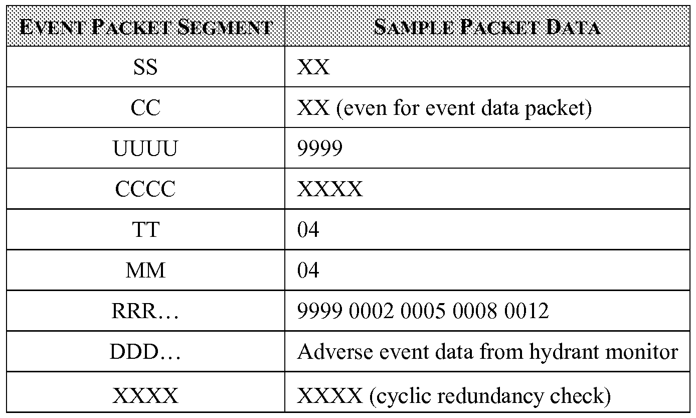
[00068] Since the UUUU segment contains unique ID 9999, this packet will be received by unit 9999 (i.e. the host server 14 identified by ID 9999 in this example). The test for "end of path" is performed on the path segment RRR. This "end of path" test can be performed in a multitude of ways, some examples of which are described here.
[00069] For example, an "end of path" test can be the number of hops test described above.
The number of hops segment TT is initialized at the host server 14 by analysis of the path segment RRR and determining the number of unique hops needed to complete the path segment RRR and the number of current hops segment MM is initialized to 01 to set the packet initially at a single current hop. Each "hop" along the segments of the path cause the current hops segment MM to be incremented. When the number of current hops MM equals the total number of hops TT, the trip is complete since the path was followed to its completion.
[00070] Another "end of path" test could be performed by simply including the unique ID of the final destination as a segment of the event data packet and the unique ID of the destination unit can be compared with the ID of the receiving unit. If they are the same, the packet is at the destination unit.
[00071] In the field of operation, the integrated communications module and controller of the communications unit 28 can be provided power in the field from a battery, such as a rechargeable battery, and a solar panel. Additionally, to reduce power consumption, the integrated communications module and controller of the communications unit 28 can be selectively powered up. For example, communications between the host server 14 and the communications units 28 may be allowed only at predetermined times during the day.
[00072] The invention provides systems and methods for gathering data from one or more remote locations and can be installed with a relatively minimum level of setup on a municipal monitoring server 16 and the equipment to detect and receive the adverse event data can be installed
in the field with relatively minimum technical assistance. The servicing of the system takes place through connections to the Internet without any modification of the municipal monitoring server 16. The invention eliminates detailed programming of the messaging system at the municipal monitoring server 16 and different programs to match each protocol of multiple diverse municipal monitoring systems. In addition, the invention provides a package of hardware that can be installed in the field on hydrants, utility poles and water towers without any special expertise in vendor hopping systems.
[00073] The systems and methods disclosed herein enable remote data collection and provisioning for a municipal monitoring server 16 that may operate and communicate using formats and protocols particular to that municipal monitoring server 16. The host server 14 may receive a communication and request for data from the municipal monitoring server 16 in the specific format or protocol of the municipal monitoring server 16. The host server 14 may then communicate with remote communications units 28 using a hopping communication protocol from the communications units located at municipal infrastructure such as hydrants, utility poles and water towers that correspond with the request from the municipal monitoring server 16. Therefore, in effect, the host server 14 may communicate with the municipal monitoring server 16 in any suitable format selected by the operator of the municipal monitoring system 10 and may further execute the process of retrieving information and/or data from remote sites in yet another protocol.
[00074] Referring now to Fig. 3, a communications device 248 (comprising the
communications unit 28 and the transceiver 17 in Fig. 1) located on a utility pole 210 and hydrant monitor located on a hydrant 200 are shown according to an embodiment of the invention. The hydrant monitor (shown in Fig. 1 as 19) comprises detectors located on the hydrant 200 and is shown as transmitting data 244 to the communications device 248 located on the utility pole 210.
[00075] Fire hydrants are well-known and accordingly will only be described herein to the extent helpful in disclosing the present invention. For purposes of disclosure, the present invention is described in connection with a conventional WaterMaster® fire hydrant available from East Jordan Iron Works of East Jordan, Michigan. The present invention is, however, readily incorporated into a wide variety of other fire hydrants as well as other municipal infrastructure, including but not limited to manhole covers and utility poles, and the present invention should not be interpreted as being limited to any particular municipal infrastructure. The hydrant 200 includes a hydrant shoe 218 which functions as an inlet, a valve seat flange 214 to receive the valve assembly 222, a lower standpipe 216, an upper standpipe 224 and a top bonnet 226 that supports, among other things, at least one nozzle 228 and the valve operating nut 230. A discharge nozzle cap 229 is threadably coupled to each nozzle 228. The hydrant 200 may include a valve 212 mounted within the valve seat flange 214. The valve seat flange 214 is disposed between the lower standpipe 216 and the hydrant shoe 218, and includes an integral liner 220 for threadably receiving the valve assembly 222. The integral liner 220 provides an integrated corrosion resistant liner for use in seating the valve assembly 222. The valve assembly
222 is threaded into the liner 220. A lower O-ring 254 is preferably fitted to facilitate a hermetic seal between the valve seat 214 and the hydrant shoe 218.
[00076] Previously described and shown in Fig. 1 , each data collecting unit comprises a transceiver coupled to a communications unit 28 that is communicably linked to a hydrant monitor 19 further comprising a suite of detector 20a-20n. In an embodiment of the invention, shown in Fig. 3, the hydrant monitor further comprises a transceiver and antenna 234 connected to a control box 232 that contains the electronics necessary for communicating data via the antenna 234 to the
communications device 248. The control box 232 additionally contains the electronics necessary for capturing and processing data collected by the detectors. The detectors, such as a nozzle cap detector 410 and a fluid level detector 418, are placed inside the fire hydrant 200 and are connected to the electronics in the control box 232 via an electrical connection 242. The detectors 410, 418 are interconnected by a series of threaded couplings 424, 426, 428, 430 (as shown in Figs. 3 and 5) to provide an electrical connection 242 that connects the detectors to the control box 232. As best seen in FIG. 3A, the hardwired electrical connection 242 may communicate sensed data to the control box 232 from the detectors, 410, 418 contained in the interior of the hydrant 200 through a co-aligned bore 314 in both the upper standpipe 224 of the hydrant 200 and the control box 232.
[00077] The electrical connection 242 may preferably be a hard-wired electrical connection consisting of one or more wires for each detector that are enclosed in a single flexible conduit 316 in FIG. 5, though a wireless connection may alternatively be implemented. The bore 314 in the hydrant may be pre-existing as a design element in the manufacture of the hydrant or may be drilled in situ to retrofit hydrants with a hydrant monitor and should be constructed as a leak free gasket encasing the electrical connection 242.
[00078] Referring now to Fig. 4, the control box 232 may contain a printed circuit board 320 with a processor 318 connected via the circuit board 320 to electronic components 312 mounted on the circuit board 320 for collecting, processing and transmitting sensed data. The control box 232 may be externally mounted to the upper standpipe 224. The hardwired electrical connections contained in the flexible conduit 316 are then connected to the circuit board 320 by conventional means well known in the art of circuit board assembly such as by multi-pin wire-to-board connectors 310. Additional elements contained in the control box 232 and connected to the processor 318 by way of electronic elements 312 on the circuit board 320 may include a battery 322 to provide power to the components of the hydrant monitor. In one embodiment of the hydrant monitor, a magnetically activated detector may be attached to the hydrant monitor to activate the unit from a sleep mode to an active mode to enable additional programming, initiate a water flow test or sense a condition indicative of undesirable tampering of the control box 232.
[00079] Referring now to Fig. 5, the hardwired electrical connections contained in the flexible conduit 316 may be traced through the bore 314 to the detector suite located inside the hydrant. The
detector suite consists of a number of detectors placed inside the standpipe and/or bonnet of the hydrant and collect data indicative of the status or condition of operable characteristics of the hydrant. As shown in Fig. 5, one preferred detector suite consists of two nozzle cap detectors 410 and 412 and a fluid level detector 418 placed in the lower standpipe 216 and connected to the other detector elements by a hardwired connection such as a two wire length contained in a conduit 414.
[00080] Nozzle cap detectors 410 and 412 output a signal to detect the removal of a nozzle cap (one of which is shown as 228 in Fig. 3). Magnets placed in each nozzle cap activate the detector. Removal of a nozzle cap separates the magnet from the detector tip and a corresponding signal is output to the processor 318 in the control box 232. The processor 318 may then transmit the data to the municipal monitoring server via the communication network previously described by "component hopping" through a predefined path of communications units to the host server and then to the municipal monitoring server by way of the Internet.
[00081] In one embodiment of the invention, the nozzle cap detectors 410 and 412 are made of flexible poll pipe with magnetically activated detectors in the tips. Flexible pipe enables the detector suite and the hydrant to be more easily serviced and allows the detector suite to be integrated into most types and configurations of hydrants. As best seen in Fig. 6, the flexible connections for the nozzle cap detectors 410 and 412 enable the bonnet 226 to be easily removed or attached to the upper standpipe. The bonnet 226 is connected by bolts (not shown) to the standpipe by aligning the plurality of bolt holes 436 on the bonnet flange 434 to the plurality of bolt holes 422 on the standpipe flange 420. When attaching the bonnet 226 to the standpipe, the nozzle cap detectors 410, 412 are fed into the nozzles 228.
[00082] Another element of the detector suite is a fluid level detector 418 that extends into the lower standpipe. The fluid level detector 418 outputs a signal to detect either the presence or absence of water at a predetermined vertical position in the lower standpipe. For example, the fluid level detector 418 may be positioned to detect the presence of water in the lower standpipe above the valve (shown in Fig. 3 with the water level 238 above valve 212). In another example, the fluid level detector may be positioned to detect the presence or absence of water in the hydrant shoe (shown in Fig. 3 with the water level 240 in the hydrant shoe 218 and the dotted line indicator for the fluid level detector 418). As indicated by dotted line 418 in FIG. 3, the fluid level detector 418 may be placed at any depth appropriate sensing the level of fluid such as water indicative of an operable condition of the hydrant. The processor 318 may transmit data indicative of an event related to the water level to the municipal monitoring server via the communication network previously described by "component hopping" through a predefined path of communications units to the host server and then to the municipal monitoring server by way of the Internet.
[00083] Referring now to Fig. 7, in one embodiment, the fluid level detector 418 is two lengths of wire 510 potted into a 90-degree fitting 512. The potted fitting 512 prevents water from
traveling up the connection 414 into the control box. The 90-degree fitting 512 enables water to roll off the tip of the detector when the water level recedes. The presence of water effectively short circuits the ends of the two lengths of wire 510. The absence of water effectively opens the circuit at the ends of the two length of wire 510. The spacing between the two lengths of wire 510 may be selected for optimal operation of the detection circuit. The fitting is shown as a 90-degree fitting, but other configurations of the wires and fitting may be used depending upon the implementation.
Further, other fluid level technologies may be used alone or in combination and may include, but not be limited to: float sensors, hydrostatic devices, load cells, magnetic level gauges, capacitance transmitters, magneto restrictive level transmitters, ultrasonic level transmitters, laser level transmitters, radar level transmitters, etc.
[00084] The detector suite outlined above may be modified to add additional sensing modalities to the hydrant monitor. Other detectors may be implemented to provide data relating to temperature, humidity, fluid pressure or any one of a number of phenomena useful for municipal infrastructure monitoring. The above-described monitoring system may be used for municipal infrastructure other than hydrants. For example, the hydrant monitors or the communications units may be integrated into manhole covers, utility poles, water meters, street lights or traffic lights.
[00085] Figs. 8-11 illustrates a a preferred embodiment of a hydrant integrated with a hydrant monitoring system in accordance with certain embodiments of the invention. The hydrant monitoring system of Figs. 1-7 is functionally the same as the hydrant monitoring system of Figs. 8-11 but the hydrant monitoring system of Figs. 8-11 have been recast into a smaller and more efficient package. In Figs. 8-1 lparts that are functional equivalent to those parts in Figs. 1-7 are identified with like numerals appended with a prime symbol, with it being understood that the functional description of the parts of Figs. 1-7 above applies to the parts of Figs. 8-11, unless otherwise noted. As shown, the detectors, such as a nozzle cap detector 410 and a fluid level detector 418, are placed inside the fire hydrant 200 and are connected to the electronics in control box 232' that extends laterally from the hydrant via an electrical connection 242. The hydrant monitor further comprises a transceiver and antenna 234' connected to the control box 232' that contains the electronics necessary for
communicating data via the antenna 234' to the communications device 248. The control box 232' can be an electrical conduit El that has an opening 232a that may be closed by a removable cover cover 232b. The cover 232b is attached to the control box through tamper-proof machine screws.
[00086] As illustrated in FIG. 9, the control box 232' is mounted to the upper standpipe 224 of a hydrant 200 through a conduit 432 and a pipe fitting 434. The pipe fitting may be threaded into the bore 314' in the upper standpipe 224. The control box 232' may contain a printed circuit board 320' with electronic components including a processor connected via the circuit board 320' to electronic components mounted on the circuit board 320' for collecting, processing and transmitting sensed data.
Additional elements contained in the control box 232' may include a battery 322' to provide power to the components of the hydrant monitor.
[00087] As illustrated in FIG. 10. a detector suite comprises three nozzle cap detectors 314,
410, 412 and a fluid level 418 that are mounted to a coupling 426'. .
[00088] As illustrated in FIG. 11 , the detector suite comprises three nozzle cap detectors and a fluid level detector placed in the standpipe of a hydrant in accordance with certain embodiments of the invention.
[00089] While described in the context of detecting and transmitting adverse event information, the method and system described above is equally applicable to transmitting data representative of a determination that no adverse data event has occurred in the remote hydrants. For example, the system may be additionally configured to generate a daily report from each remote hydrant that indicates that each hydrant and hydrant monitor is operating correctly. That is, no adverse event in the hydrant has been detected by the hydrant monitor and the hydrant monitor is operating within acceptable parameters. Reporting the state or condition of the components in the hydrant or hydrant monitor in this manner may occur according to a user-defined schedule, whereby
predetermined times are selected for determining that no adverse event has occurred in the remote hydrants. Alternatively, the municipal monitoring server may default to a condition of no adverse event unless an adverse event data packet is transmitted from the host server.
[00090] Data representative of the determination of a non-adverse condition may be transferred from the hydrant to the host server and then from the host server to the municipal monitoring server. In this way, the system may regularly update and actively inform an operator (e.g. with a visual representation that quickly shows the status of each monitored hydrant) of the status of the entire system and its constituent components. The predetermined time of the reporting of the status or non-adverse conditions of a remote hydrant may vary depending upon the implementation. However, it is contemplated that a desireable user-defined schedule may include a 24 hour duration of time. That is, daily reports may be optimal for an operator of the system to receive data that describes the condition or status of the hydrant and hydrant monitor components, including but not limited to a battery level and the condition of the hydrant monitor sensors.
[00091] Reasonable variation and modification are possible within the forgoing description and drawings without departing from the spirit of the invention. While the invention has been specifically described in connection with certain specific embodiments thereof, it is to be understood that this is by way of illustration and not of limitation, and the scope of the appended claims should be construed as broadly as the prior art will permit.
Claims
1. A method for transferring adverse event information from a plurality of remote hydrants to a municipal monitoring server comprises:
detecting an adverse event that occurs in one of the remote hydrants;
generating adverse event data representative of the adverse event;
transferring the adverse event data representative of the adverse condition from the one remote hydrant to a host server by routing the adverse event data along a wireless predefined hopping path; and
transferring the adverse event data from the host server to the municipal monitoring server.
2. The method of claim 1 wherein the adverse event is an event that would render the hydrant wholly or partially inoperative.
3. The method of claim 1 wherein the adverse event includes at least one of the removal of a nozzle cap from the hydrant the presence of a predetermined level of fluid in the hydrant and tampering of the hydrant.
4. The method of claim 1 wherein the act of transferring the adverse event data to the host server includes adding to the adverse event data the wireless predefined hopping path.
5. The method of claim 4 and further comprising removing the wireless predefined hopping path from the adverse event data at the host server prior to transferring the adverse event data to the municipal monitoring server.
6. The method of claim 1 wherein the act of transferring the adverse event data from the host monitor to the municipal monitoring server takes place through a network.
7. The method of claim 6 wherein the host server is geographically remote from the municipal monitoring server.
8. The method of claim 1 wherein the remote hydrant has a hydrant monitor which has a sleep mode, and further comprising waking the hydrant monitor, and generating the data
representative of the adverse condition.
9. The method of claim 1 further comprising:
determining that no adverse event has occurred in one of the remote hydrants; and transferring data representative of the determination from the one remote hydrant to the host server and from the host server to the municipal monitoring server.
10. The method of claim 9 wherein the steps of determining and transferring data representative of the determination occur at predetermined times.
1 1. The method of claim 10 wherein the predetermined times are selected according to a user-defined schedule.
12. A system for collecting data representative of events relating to an adverse condition in a fire hydrant that is outside of wireless communication proximity to a municipal monitoring server, comprising;
a host server configured to communicate data packets with the municipal monitoring server; a plurality of transmission communication units positioned in a geographic region outside of wireless communication proximity to a municipal monitoring server wherein at least one of the transmission communication units is in wireless proximity to the fire hydrant and at least one other of the transmission communication units is in wireless proximity to the host server; and further wherein the plurality of transmission communication units are positioned so that there is at least one hopping path of wireless communication between the fire hydrant and the host server;
a detector mounted to the fire hydrant, wherein the detector is configured to detect an event in the hydrant of an adverse hydrant condition in the hydrant and to generate an adverse event signal in response to the adverse event;
a hydrant monitor mounted to the fire hydrant and connected to the detector for receiving a signal from the detector and configured to convert the adverse event signal from the detector into an event data packet and to wirelessly transmit the event data packet to one of the transmission communication units in wireless proximity to the fire hydrant;
wherein the transmission communication units are configured to transmit the event data packet to the host server through a predefined hopping path for sending the same to the municipal monitoring server.
13. The system of claim 12 wherein the transmission communication units are mounted to structural supports in positions that are inaccessible to the public.
14. The system of claim 12 wherein transmission communication units are mounted to structural supports that include utility poles and buildings.
15. The system of claim 12 wherein there are multiple hydrants geographically spaced from, but in wireless proximity to, at least one of the transmission communication units and each of the hydrants is equipped with one of the detectors and one hydrant monitors.
16. The system of claim 12 wherein the host server is geographically remote from the municipal monitoring server and is configured to communicate with the municipal monitoring server through a network.
17. The system of claim 12 wherein there are multiple detectors in the hydrant, each of which detectors is configured to detect an adverse event of a different adverse hydrant condition in the hydrant and to generate a different adverse event signal in response to the adverse event.
18. The system of claim 12 wherein the hydrant monitor has a sleep mode, and the hydrant monitor is configured to wake up responsive to the adverse event signal and to convert the adverse event signal from the detector into an event data packet responsive thereto.
19. The system of claim 12 wherein the transmission communication units are configured to add the predefined hopping path to the event data packet.
20. The system of claim 19 wherein the host server is configured to strip the predefined hopping path from the event data packet prior to sending the event data packet to the municipal monitoring server.
21. The system of claim 12 wherein the municipal monitoring server defaults to a condition of no adverse event unless an event data packet is transmitted from the host server.
22. The system of claim 12 wherein the hydrant monitor is further configured to wirelessly transmit a signal representing that no adverse event signal has been received from a detector at a given time.
23. The system of claim 22 wherein the given time is predetermined according to a user- defined schedule.
24. The system of claim 12 wherein the hydrant monitor is further configured to wirelessly transmit a signal representing that no adverse event signal has been received from a detector within a predetermined duration of time.
25. The system of claim 24 wherein the predetermined duration of time is the preceding 24 hours.
26. A method for transferring adverse event information from a plurality of remote hydrants to a municipal monitoring server comprises:
detecting an adverse event in one of the plurality of remote hydrants that may relate to an adverse hydrant condition; and
transferring data representative of the adverse condition to the municipal monitoring server at least in part by routing the data along a wireless predefined hopping path of transmission communication units.
Priority Applications (4)
| Application Number | Priority Date | Filing Date | Title |
|---|---|---|---|
| US14/892,604 US20160093193A1 (en) | 2013-05-21 | 2014-05-20 | Hydrant monitoring system and method |
| CA2912839A CA2912839C (en) | 2013-05-21 | 2014-05-20 | Hydrant monitoring system and method |
| US15/363,831 US9873008B2 (en) | 2013-05-21 | 2016-11-29 | Hydrant monitoring system and method |
| US15/493,547 US9901765B2 (en) | 2013-05-21 | 2017-04-21 | Hydrant monitoring system and method |
Applications Claiming Priority (2)
| Application Number | Priority Date | Filing Date | Title |
|---|---|---|---|
| US201361825797P | 2013-05-21 | 2013-05-21 | |
| US61/825,797 | 2013-05-21 |
Related Child Applications (2)
| Application Number | Title | Priority Date | Filing Date |
|---|---|---|---|
| US14/892,604 A-371-Of-International US20160093193A1 (en) | 2013-05-21 | 2014-05-20 | Hydrant monitoring system and method |
| US15/363,831 Continuation US9873008B2 (en) | 2013-05-21 | 2016-11-29 | Hydrant monitoring system and method |
Publications (1)
| Publication Number | Publication Date |
|---|---|
| WO2014189901A1 true WO2014189901A1 (en) | 2014-11-27 |
Family
ID=51934037
Family Applications (1)
| Application Number | Title | Priority Date | Filing Date |
|---|---|---|---|
| PCT/US2014/038747 WO2014189901A1 (en) | 2013-05-21 | 2014-05-20 | Hydrant monitoring system and method |
Country Status (3)
| Country | Link |
|---|---|
| US (2) | US20160093193A1 (en) |
| CA (1) | CA2912839C (en) |
| WO (1) | WO2014189901A1 (en) |
Cited By (7)
| Publication number | Priority date | Publication date | Assignee | Title |
|---|---|---|---|---|
| CN104597887A (en) * | 2015-01-28 | 2015-05-06 | 深圳市开天源自动化工程有限公司 | Intelligent fire hydrant remote monitoring system |
| DE202015006930U1 (en) | 2015-09-29 | 2015-11-10 | Berliner Wasserbetriebe Anstalt des öffentlichen Rechts | Retractable removal fitting |
| CN105825617A (en) * | 2016-05-27 | 2016-08-03 | 赵汝杰 | Fire hydrant remote monitoring device and fire hydrant remote monitoring method |
| CN106149807A (en) * | 2016-08-16 | 2016-11-23 | 嘉禾县恒鑫建材有限公司 | A kind of fire hydrant autoalarm |
| US10921304B2 (en) | 2015-09-21 | 2021-02-16 | AMI Investments, LLC | Remote monitoring of water distribution system |
| CN115086794A (en) * | 2022-05-25 | 2022-09-20 | 三峡大学 | Networked monitoring system and early warning method for fire valve |
| CN115086794B (en) * | 2022-05-25 | 2024-04-19 | 三峡大学 | Networked monitoring system and early warning method for fire valve |
Families Citing this family (42)
| Publication number | Priority date | Publication date | Assignee | Title |
|---|---|---|---|---|
| US8489562B1 (en) | 2007-11-30 | 2013-07-16 | Silver Peak Systems, Inc. | Deferred data storage |
| US8885632B2 (en) | 2006-08-02 | 2014-11-11 | Silver Peak Systems, Inc. | Communications scheduler |
| US9717021B2 (en) | 2008-07-03 | 2017-07-25 | Silver Peak Systems, Inc. | Virtual network overlay |
| US10164861B2 (en) | 2015-12-28 | 2018-12-25 | Silver Peak Systems, Inc. | Dynamic monitoring and visualization for network health characteristics |
| US10805840B2 (en) | 2008-07-03 | 2020-10-13 | Silver Peak Systems, Inc. | Data transmission via a virtual wide area network overlay |
| US9818073B2 (en) * | 2009-07-17 | 2017-11-14 | Honeywell International Inc. | Demand response management system |
| EP2582886B1 (en) | 2010-06-16 | 2019-11-27 | Mueller International, LLC | Infrastructure monitoring devices, systems, and methods |
| US9593999B2 (en) | 2011-08-12 | 2017-03-14 | Mueller International, Llc | Enclosure for leak detector |
| US9130991B2 (en) | 2011-10-14 | 2015-09-08 | Silver Peak Systems, Inc. | Processing data packets in performance enhancing proxy (PEP) environment |
| US9948496B1 (en) * | 2014-07-30 | 2018-04-17 | Silver Peak Systems, Inc. | Determining a transit appliance for data traffic to a software service |
| US9875344B1 (en) | 2014-09-05 | 2018-01-23 | Silver Peak Systems, Inc. | Dynamic monitoring and authorization of an optimization device |
| US10283857B2 (en) * | 2016-02-12 | 2019-05-07 | Mueller International, Llc | Nozzle cap multi-band antenna assembly |
| US10305178B2 (en) | 2016-02-12 | 2019-05-28 | Mueller International, Llc | Nozzle cap multi-band antenna assembly |
| US20170336380A1 (en) * | 2016-05-23 | 2017-11-23 | John C. Kupferle Foundry Company | Portable flushing monitor |
| US10432484B2 (en) | 2016-06-13 | 2019-10-01 | Silver Peak Systems, Inc. | Aggregating select network traffic statistics |
| US9967056B1 (en) | 2016-08-19 | 2018-05-08 | Silver Peak Systems, Inc. | Forward packet recovery with constrained overhead |
| CN106730561A (en) * | 2016-12-12 | 2017-05-31 | 互联智控科技(天津)有限公司 | Fire hydrant water pressure monitoring system and monitoring method |
| US10771394B2 (en) | 2017-02-06 | 2020-09-08 | Silver Peak Systems, Inc. | Multi-level learning for classifying traffic flows on a first packet from DNS data |
| US10892978B2 (en) | 2017-02-06 | 2021-01-12 | Silver Peak Systems, Inc. | Multi-level learning for classifying traffic flows from first packet data |
| US10257082B2 (en) | 2017-02-06 | 2019-04-09 | Silver Peak Systems, Inc. | Multi-level learning for classifying traffic flows |
| US11044202B2 (en) | 2017-02-06 | 2021-06-22 | Silver Peak Systems, Inc. | Multi-level learning for predicting and classifying traffic flows from first packet data |
| CN110325248A (en) * | 2017-02-21 | 2019-10-11 | 海德兰泰克股份有限公司 | The method and system of flow in fire hydrant outlet for identification |
| US11212210B2 (en) | 2017-09-21 | 2021-12-28 | Silver Peak Systems, Inc. | Selective route exporting using source type |
| CN107693998A (en) * | 2017-10-31 | 2018-02-16 | 深圳市华士精成科技有限公司 | A kind of fire fighting device water pressure monitoring device and monitoring system |
| US10637721B2 (en) | 2018-03-12 | 2020-04-28 | Silver Peak Systems, Inc. | Detecting path break conditions while minimizing network overhead |
| CN108643282A (en) * | 2018-06-28 | 2018-10-12 | 山东众海智能科技有限公司 | A kind of Outdoor Fire Hydrant and fire hydrant monitoring system |
| US10859462B2 (en) | 2018-09-04 | 2020-12-08 | Mueller International, Llc | Hydrant cap leak detector with oriented sensor |
| US11342656B2 (en) | 2018-12-28 | 2022-05-24 | Mueller International, Llc | Nozzle cap encapsulated antenna system |
| US11067464B2 (en) * | 2019-01-18 | 2021-07-20 | Mueller International, Llc | Wet barrel hydrant with pressure monitoring and leak detection |
| US11473993B2 (en) | 2019-05-31 | 2022-10-18 | Mueller International, Llc | Hydrant nozzle cap |
| US11400328B2 (en) | 2019-06-07 | 2022-08-02 | Mueller International, Llc | Hydrant monitoring communications hub |
| US10941545B2 (en) | 2019-06-07 | 2021-03-09 | Mueller International, Llc | Hydrant monitoring system |
| US10968609B2 (en) | 2019-06-07 | 2021-04-06 | Mueller International, Llc | Self-contained hydrant monitoring system |
| US10934693B2 (en) * | 2019-06-07 | 2021-03-02 | Mueller International, Llc | Hydrant monitoring system |
| JP2021131630A (en) * | 2020-02-18 | 2021-09-09 | 株式会社東芝 | Monitoring control device and client PC |
| US11542690B2 (en) | 2020-05-14 | 2023-01-03 | Mueller International, Llc | Hydrant nozzle cap adapter |
| CN112206456A (en) * | 2020-10-16 | 2021-01-12 | 湖南菲尔斯特传感器有限公司 | Fire hydrant monitoring system |
| CN112190863B (en) * | 2020-10-27 | 2021-10-01 | 上海西邦电气有限公司 | Capacity-sensing intelligent fire extinguisher and capacity sensing method |
| CN112402885A (en) * | 2020-12-21 | 2021-02-26 | 杭州智缤科技有限公司 | Installation and debugging method of intelligent fire hydrant |
| US20230052748A1 (en) * | 2021-08-12 | 2023-02-16 | Silversmith, Inc. | Sensor conduit support structure |
| CN115006770B (en) * | 2022-04-28 | 2023-02-21 | 诠航科技有限公司 | State judgment method, state judgment device and intelligent fire hydrant box system |
| CN114949707B (en) * | 2022-05-27 | 2023-07-28 | 杭州海康消防科技有限公司 | Monitoring device for fire hydrant, state monitoring method and state monitoring device |
Citations (5)
| Publication number | Priority date | Publication date | Assignee | Title |
|---|---|---|---|---|
| US6031455A (en) * | 1998-02-09 | 2000-02-29 | Motorola, Inc. | Method and apparatus for monitoring environmental conditions in a communication system |
| US6842430B1 (en) * | 1996-10-16 | 2005-01-11 | Koninklijke Philips Electronics N.V. | Method for configuring and routing data within a wireless multihop network and a wireless network for implementing the same |
| US7242317B2 (en) * | 2003-05-20 | 2007-07-10 | Silversmith, Inc. | Wireless well communication system and method |
| US20100295672A1 (en) * | 2009-05-22 | 2010-11-25 | Mueller International, Inc. | Infrastructure monitoring devices, systems, and methods |
| US7983869B1 (en) * | 2007-05-07 | 2011-07-19 | Hurley Lyndon J | Flow testing system for fluid networks |
Family Cites Families (8)
| Publication number | Priority date | Publication date | Assignee | Title |
|---|---|---|---|---|
| CA2154433A1 (en) | 1995-07-21 | 1997-01-22 | Mario Parisi | Freeze and water detector for a fire hydrant |
| US6390027B1 (en) * | 2000-05-31 | 2002-05-21 | C. Cowles & Company | Cycle control system for boiler and associated burner |
| WO2003049528A2 (en) | 2001-12-07 | 2003-06-19 | Michael Zoratti | Fire hydrant anti-tamper device |
| US8657021B1 (en) * | 2004-11-16 | 2014-02-25 | Joseph Frank Preta | Smart fire hydrants |
| CA2725065A1 (en) * | 2008-05-20 | 2009-11-26 | Live Meters, Inc. | Remote monitoring and control system comprising mesh and time synchronization technology |
| US9593999B2 (en) * | 2011-08-12 | 2017-03-14 | Mueller International, Llc | Enclosure for leak detector |
| US8614745B1 (en) * | 2013-02-04 | 2013-12-24 | Wasmeyyah M. A. S. Al Azemi | Fire hydrant monitoring system |
| US9670650B2 (en) * | 2015-11-09 | 2017-06-06 | Sensus Spectrum Llc | Fire hydrant monitoring system |
-
2014
- 2014-05-20 US US14/892,604 patent/US20160093193A1/en not_active Abandoned
- 2014-05-20 WO PCT/US2014/038747 patent/WO2014189901A1/en active Application Filing
- 2014-05-20 CA CA2912839A patent/CA2912839C/en active Active
-
2016
- 2016-11-29 US US15/363,831 patent/US9873008B2/en active Active
Patent Citations (5)
| Publication number | Priority date | Publication date | Assignee | Title |
|---|---|---|---|---|
| US6842430B1 (en) * | 1996-10-16 | 2005-01-11 | Koninklijke Philips Electronics N.V. | Method for configuring and routing data within a wireless multihop network and a wireless network for implementing the same |
| US6031455A (en) * | 1998-02-09 | 2000-02-29 | Motorola, Inc. | Method and apparatus for monitoring environmental conditions in a communication system |
| US7242317B2 (en) * | 2003-05-20 | 2007-07-10 | Silversmith, Inc. | Wireless well communication system and method |
| US7983869B1 (en) * | 2007-05-07 | 2011-07-19 | Hurley Lyndon J | Flow testing system for fluid networks |
| US20100295672A1 (en) * | 2009-05-22 | 2010-11-25 | Mueller International, Inc. | Infrastructure monitoring devices, systems, and methods |
Cited By (10)
| Publication number | Priority date | Publication date | Assignee | Title |
|---|---|---|---|---|
| CN104597887A (en) * | 2015-01-28 | 2015-05-06 | 深圳市开天源自动化工程有限公司 | Intelligent fire hydrant remote monitoring system |
| US10921304B2 (en) | 2015-09-21 | 2021-02-16 | AMI Investments, LLC | Remote monitoring of water distribution system |
| US11371977B2 (en) | 2015-09-21 | 2022-06-28 | AMI Investments, LLC | Remote monitoring of water distribution system |
| US11391712B2 (en) | 2015-09-21 | 2022-07-19 | AMI Investments, LLC | Remote monitoring of water distribution system |
| US11460459B2 (en) | 2015-09-21 | 2022-10-04 | AMI Investments, LLC | Remote monitoring of water distribution system |
| DE202015006930U1 (en) | 2015-09-29 | 2015-11-10 | Berliner Wasserbetriebe Anstalt des öffentlichen Rechts | Retractable removal fitting |
| CN105825617A (en) * | 2016-05-27 | 2016-08-03 | 赵汝杰 | Fire hydrant remote monitoring device and fire hydrant remote monitoring method |
| CN106149807A (en) * | 2016-08-16 | 2016-11-23 | 嘉禾县恒鑫建材有限公司 | A kind of fire hydrant autoalarm |
| CN115086794A (en) * | 2022-05-25 | 2022-09-20 | 三峡大学 | Networked monitoring system and early warning method for fire valve |
| CN115086794B (en) * | 2022-05-25 | 2024-04-19 | 三峡大学 | Networked monitoring system and early warning method for fire valve |
Also Published As
| Publication number | Publication date |
|---|---|
| CA2912839A1 (en) | 2014-11-27 |
| CA2912839C (en) | 2019-04-30 |
| US9873008B2 (en) | 2018-01-23 |
| US20170072238A1 (en) | 2017-03-16 |
| US20160093193A1 (en) | 2016-03-31 |
Similar Documents
| Publication | Publication Date | Title |
|---|---|---|
| US9873008B2 (en) | Hydrant monitoring system and method | |
| US9901765B2 (en) | Hydrant monitoring system and method | |
| US8924587B2 (en) | Systems and methods for controlling communication between a host computer and communication devices | |
| US7242317B2 (en) | Wireless well communication system and method | |
| US6836737B2 (en) | Systems and methods for providing remote monitoring of consumption for a utility meter | |
| CA2885968C (en) | Data packet transport and delivery system and method | |
| CN102577427A (en) | A monitoring system | |
| US20110316707A1 (en) | Remote monitoring system for multiple steam traps | |
| CA3002309C (en) | Hydrant monitoring system and method | |
| US20060197678A1 (en) | Wireless well communication system and method | |
| CN110599618A (en) | Underground pipeline data monitoring method, device and system | |
| CN102289910A (en) | Intelligent fire early warning monitoring system | |
| KR100800616B1 (en) | Monitoring system using Zigbee | |
| CN103296749A (en) | Method and system for processing power grid state information based on wireless sensor network | |
| CN112737099B (en) | Edge gateway and integrated energy system | |
| KR100766441B1 (en) | Monitoring system using zigbee | |
| CN215647388U (en) | Water supply and drainage monitoring system | |
| CN108488631A (en) | A kind of heat distribution pipe network remote supervision system based on big-dipper satellite | |
| CN106549491A (en) | A kind of electric network fault real-time detecting system | |
| TW201935888A (en) | Cloud management bridge and cloud management system capable of transmitting client date generated by client to server on Internet to achieve remote monitoring purpose | |
| CN113380003A (en) | Multi-disaster event chain comprehensive monitoring and early warning device |
Legal Events
| Date | Code | Title | Description |
|---|---|---|---|
| 121 | Ep: the epo has been informed by wipo that ep was designated in this application |
Ref document number: 14800915 Country of ref document: EP Kind code of ref document: A1 |
|
| ENP | Entry into the national phase |
Ref document number: 2912839 Country of ref document: CA |
|
| NENP | Non-entry into the national phase |
Ref country code: DE |
|
| 122 | Ep: pct application non-entry in european phase |
Ref document number: 14800915 Country of ref document: EP Kind code of ref document: A1 |