WO2014189083A1 - Molding diagnosis device - Google Patents
Molding diagnosis device Download PDFInfo
- Publication number
- WO2014189083A1 WO2014189083A1 PCT/JP2014/063487 JP2014063487W WO2014189083A1 WO 2014189083 A1 WO2014189083 A1 WO 2014189083A1 JP 2014063487 W JP2014063487 W JP 2014063487W WO 2014189083 A1 WO2014189083 A1 WO 2014189083A1
- Authority
- WO
- WIPO (PCT)
- Prior art keywords
- molding
- deviation
- unit
- reference value
- value
- Prior art date
Links
Images


Classifications
-
- B—PERFORMING OPERATIONS; TRANSPORTING
- B29—WORKING OF PLASTICS; WORKING OF SUBSTANCES IN A PLASTIC STATE IN GENERAL
- B29C—SHAPING OR JOINING OF PLASTICS; SHAPING OF MATERIAL IN A PLASTIC STATE, NOT OTHERWISE PROVIDED FOR; AFTER-TREATMENT OF THE SHAPED PRODUCTS, e.g. REPAIRING
- B29C45/00—Injection moulding, i.e. forcing the required volume of moulding material through a nozzle into a closed mould; Apparatus therefor
- B29C45/17—Component parts, details or accessories; Auxiliary operations
- B29C45/76—Measuring, controlling or regulating
- B29C45/78—Measuring, controlling or regulating of temperature
-
- B—PERFORMING OPERATIONS; TRANSPORTING
- B29—WORKING OF PLASTICS; WORKING OF SUBSTANCES IN A PLASTIC STATE IN GENERAL
- B29C—SHAPING OR JOINING OF PLASTICS; SHAPING OF MATERIAL IN A PLASTIC STATE, NOT OTHERWISE PROVIDED FOR; AFTER-TREATMENT OF THE SHAPED PRODUCTS, e.g. REPAIRING
- B29C2945/00—Indexing scheme relating to injection moulding, i.e. forcing the required volume of moulding material through a nozzle into a closed mould
- B29C2945/76—Measuring, controlling or regulating
- B29C2945/76003—Measured parameter
- B29C2945/7604—Temperature
-
- B—PERFORMING OPERATIONS; TRANSPORTING
- B29—WORKING OF PLASTICS; WORKING OF SUBSTANCES IN A PLASTIC STATE IN GENERAL
- B29C—SHAPING OR JOINING OF PLASTICS; SHAPING OF MATERIAL IN A PLASTIC STATE, NOT OTHERWISE PROVIDED FOR; AFTER-TREATMENT OF THE SHAPED PRODUCTS, e.g. REPAIRING
- B29C2945/00—Indexing scheme relating to injection moulding, i.e. forcing the required volume of moulding material through a nozzle into a closed mould
- B29C2945/76—Measuring, controlling or regulating
- B29C2945/76177—Location of measurement
- B29C2945/7618—Injection unit
- B29C2945/7621—Injection unit nozzle
-
- B—PERFORMING OPERATIONS; TRANSPORTING
- B29—WORKING OF PLASTICS; WORKING OF SUBSTANCES IN A PLASTIC STATE IN GENERAL
- B29C—SHAPING OR JOINING OF PLASTICS; SHAPING OF MATERIAL IN A PLASTIC STATE, NOT OTHERWISE PROVIDED FOR; AFTER-TREATMENT OF THE SHAPED PRODUCTS, e.g. REPAIRING
- B29C2945/00—Indexing scheme relating to injection moulding, i.e. forcing the required volume of moulding material through a nozzle into a closed mould
- B29C2945/76—Measuring, controlling or regulating
- B29C2945/76494—Controlled parameter
- B29C2945/76531—Temperature
-
- B—PERFORMING OPERATIONS; TRANSPORTING
- B29—WORKING OF PLASTICS; WORKING OF SUBSTANCES IN A PLASTIC STATE IN GENERAL
- B29C—SHAPING OR JOINING OF PLASTICS; SHAPING OF MATERIAL IN A PLASTIC STATE, NOT OTHERWISE PROVIDED FOR; AFTER-TREATMENT OF THE SHAPED PRODUCTS, e.g. REPAIRING
- B29C2945/00—Indexing scheme relating to injection moulding, i.e. forcing the required volume of moulding material through a nozzle into a closed mould
- B29C2945/76—Measuring, controlling or regulating
- B29C2945/76655—Location of control
- B29C2945/76658—Injection unit
- B29C2945/76688—Injection unit nozzle
-
- B—PERFORMING OPERATIONS; TRANSPORTING
- B29—WORKING OF PLASTICS; WORKING OF SUBSTANCES IN A PLASTIC STATE IN GENERAL
- B29C—SHAPING OR JOINING OF PLASTICS; SHAPING OF MATERIAL IN A PLASTIC STATE, NOT OTHERWISE PROVIDED FOR; AFTER-TREATMENT OF THE SHAPED PRODUCTS, e.g. REPAIRING
- B29C2945/00—Indexing scheme relating to injection moulding, i.e. forcing the required volume of moulding material through a nozzle into a closed mould
- B29C2945/76—Measuring, controlling or regulating
- B29C2945/76929—Controlling method
- B29C2945/76939—Using stored or historical data sets
Definitions
- the present invention relates to a molding diagnostic apparatus provided in a molding machine such as an injection molding machine or a die casting machine, and particularly relates to a machine that diagnoses the stability of the operation of the molding machine during continuous automatic operation.
- Molding machines such as injection molding machines and die casting machines are equipped with molding condition setting devices that set molding conditions.
- the molding condition setting device Prior to the operation of the molding machine, the molding condition setting device is operated to operate a molded product. It is necessary to input required molding conditions according to the conditions.
- the molding conditions of the molding machine are diverse, skill is required to set the molding conditions, and it is difficult for an unskilled person to efficiently set all the setting items required.
- a device for simplifying the operation when setting the molding conditions and a device for preventing forgetting to change the set value have been added.
- Various molding condition setting devices have been proposed (see, for example, Patent Documents 1, 2, and 3).
- JP-A-5-42571 JP 2008-114403 A Japanese Patent No. 4094194
- the operation of the molding machine becomes unstable during continuous automatic operation, and a molded product that does not reach the target quality is molded, or the target shot cycle is obtained. Inconveniences such as inability to occur may occur.
- the present invention has been made to solve such deficiencies in the prior art, and its purpose is to continuously diagnose the operational stability of the molding machine detected during continuous automatic operation, and to provide a display device.
- An object of the present invention is to provide a molding diagnostic apparatus for displaying a required message and notifying an operator.
- the present invention includes a mold opening / closing device and an injection device for injecting a molding material into a mold clamped by the opening / closing device, and a predetermined molding including a plurality of steps.
- a molding machine body that continuously molds a predetermined molded product by repeating a cycle, a molding condition setting means for an operator to set molding conditions for the molding machine body, and a molding condition setting set in the molding condition setting means
- Control means for controlling the driving of the molding machine main body based on the value, and measuring means provided in a predetermined part of the molding machine main body for measuring and outputting a measurement value according to the operating state of the molding machine main body
- Is a molding diagnostic apparatus that determines the operational stability of the molding machine body during continuous automatic operation and notifies an operator of the molding diagnostic apparatus, and sets the number of shots that serves as a criterion for determining the operational stability.
- a shot number setting unit, a measurement value of the measurement unit, an input unit of the shot number set in the shot number setting unit, a reference value for determining the operational stability of the molding machine body, and A storage unit that stores measurement values of the measurement unit, a calculation unit that calculates a deviation of the measurement values for the number of shots stored in the storage unit, and the number of inputs of the measurement values to the input unit Determines whether or not the number of shots set in the shot number setting unit has reached the number of shots and whether or not the deviation of the measured value for the number of shots is equal to or greater than a reference value stored in the storage unit
- the control means The specific judgment display according to the type and outputs to the monitor unit.
- the diagnostic items of the molding machine main body include at least one item selected from nozzle temperature, primary injection time, mold opening time, mold closing time, and molded product removal time, filling pressure, metering motor torque, and screw during metering. Can be set in the storage unit.
- the reference value the reference value of the deviation of the nozzle temperature, the reference value of the deviation relating to the primary injection time, the mold opening time, the mold closing time and the removal time of the molded product, depending on the diagnosis item, filling from the start of filling Reference value for deviation of filling pressure for each measurement time until the end, reference value for deviation of weighing motor torque for each measurement time from the start of measurement to the end of measurement, Treatment speed of the screw for each measurement time from the start of measurement to the end of measurement
- the reference value of the deviation can be stored.
- Diagnosis of the molding machine body can be performed separately for each diagnostic item, and when the diagnosis of the molding machine body is instructed by the operator during continuous automatic operation, all diagnostic items set in the storage unit are automatically It can also be executed automatically.
- the control unit displays a specific determination display according to the type of measurement value Is output to the monitor unit, the operator can reliably recognize the operational stability of the molding machine body. Therefore, it becomes possible for an operator to take an appropriate response quickly, and a good product can be manufactured with high efficiency.
- gist of the present invention is not limited to the following embodiments, and it is needless to say that the gist of the present invention can be easily applied to molding machines having other configurations without departing from the spirit of the invention.
- the molding diagnostic apparatus 1 includes a molding machine body 10 including a sensor group (measuring unit) 11, a control unit 20, and a molding condition setting unit 30.
- the operation stability of the molding machine body 10 during continuous automatic operation is diagnosed.
- the molding diagnostic apparatus 1 includes a start switch 40, an input device 50 for inputting a diagnostic item of the molding machine body 10 and a reference value of operational stability regarding each diagnostic item, and a calculation of the operational stability of the molding machine body 10.
- a shot number setting unit 60 is provided for setting the number of shots, which is the number of samples of measurement value data output from the sensor group 11.
- the molding machine main body 10 includes a mold opening / closing device and an injection device that injects a molding material into the clamped mold, and includes a metering process, a mold closing process, a mold clamping process, an injection process, a mold opening process, and A predetermined molded product is formed by repeating a predetermined molding cycle including a product removal step and the like.
- the molding machine body 10 according to the embodiment may be either an injection molding machine that molds plastic products or a die casting machine that molds light metal products.
- the sensor group 11 is installed in a predetermined part of the opening / closing device and the injection device, and outputs appropriate measurement value data according to the operating state of the molding machine body 10 during continuous automatic operation.
- the measurement value data output from these sensor groups 11 is input to the molding diagnostic apparatus 1 and the control means 20.
- a peripheral device (not shown) such as a product take-out device is also arranged around the molding machine body 10 as necessary.
- the configurations of the molding machine main body 10 and peripheral devices are known matters and are not the gist of the present invention.
- the control means 20 is responsible for overall driving of the molding diagnostic apparatus 1, the molding machine body 10, and peripheral devices, and molding conditions determined by the molding condition setting values set in the molding condition setting means 30 and the specifications of the molding machine body 10. Based on the reference value and the measured value data output from the sensor group 11, the driving of the mold opening / closing device and the injection device is controlled, and the predetermined molding cycle described above is repeatedly executed.
- the molding condition setting means 30 is for the operator to input an appropriate molding condition setting value that matches the characteristics of the molded product to be molded before the molding machine body 10 starts operation. Any molding condition setting device belonging to the public knowledge such as those described in No. 3 can be used.
- the molding conditions to be set in the molding condition setting device 30 are various. For example, primary pressure setting in the injection process, injection timer setting, pressure holding speed setting, pressure holding time setting, measuring process time in the measuring process, and suckback Examples include low pressure mold clamping, low pressure mold clamping torque, and low pressure mold clamping time in the setting and mold opening / closing process.
- the molding diagnostic apparatus 1 is input to the measured value data output from the sensor group 11, the control signal output from the control means 20, the switch signal output from the start switch 40, and the input device 50.
- the input unit 2 takes in the diagnostic item data, the reference value data, the determination message to be displayed to the operator, and the shot number data set in the shot number setting unit 60.
- the molding diagnosis apparatus 1 includes the storage unit 4 that stores the above-described data captured in the input unit, and the maximum value of the measurement value data sampled over the number of shots set in the shot number setting unit 60. It has the calculating part 3 which calculates the deviation of the minimum value.
- the molding diagnostic apparatus 1 determines whether or not the number of measurement value data input to the input unit 2 has reached the number of shots set in the shot number setting unit 60 and the number of shots determined by the calculation unit 3.
- the determination unit 5 determines whether or not the deviation of the measured value data is larger than the reference value data stored in the storage unit 4.
- the molding diagnosis apparatus 1 includes a monitor unit 6 that displays various data stored in the calculation unit 3 and a required determination message according to the determination result of the determination unit 5 in a predetermined format, and the required data.
- the molding condition diagnosis apparatus 1 can also be configured integrally with the above-described control unit 20 and molding condition setting unit 30.
- the molding diagnostic apparatus 1 is activated when the operator operates the activation switch 40, and for each diagnostic item stored in the storage unit 4, a deviation of measured value data for a predetermined number of shots is stored in the storage unit 4. It is automatically determined whether or not it is larger than the reference value data, and a molding diagnosis relating to a required diagnosis item is performed. That is, as shown in FIG. 2, the operator sets a molding condition setting value in the molding condition setting unit 30 and activates the control unit 20 to start continuous automatic operation of the molding machine body 10. By operating, the molding diagnostic apparatus 1 can be started at any time.
- the molding diagnostic apparatus 1 When the molding diagnostic apparatus 1 is activated, the measurement value data is sampled for the number of shots preset in the storage unit 4 in accordance with the operation program stored in the storage unit 4, and based on the sampled measurement value data Thus, a molding diagnosis for a preset diagnostic item is automatically executed by the determination unit 5. A predetermined determination message corresponding to the determination result is read from the storage unit 4, output from the monitor driver 7, and displayed on the monitor unit 6. The operator can confirm the determination message and take necessary countermeasures such as changing the molding condition setting value as necessary.
- the continuous automatic operation can be continued as it is.
- the above-described molding diagnosis can be performed continuously for all diagnostic items stored in the storage unit 4 when the molding diagnosis apparatus 1 is activated, or selected by the operator. It is also possible to selectively perform only the molding diagnosis for the diagnosis items.
- the reference value the reference value of the deviation of the nozzle temperature, the reference value of the deviation relating to the primary injection time, the mold opening time, the mold closing time and the removal time of the molded product, depending on the diagnosis item, filling from the start of filling Reference value for deviation of filling pressure for each measurement time until the end, reference value for deviation of weighing motor torque for each measurement time from the start of measurement to the end of measurement, Treatment speed of the screw for each measurement time from the start of measurement to the end of measurement Is stored in the storage unit 4.
- an allowable range for manufacturing a non-defective product with high efficiency is set as a reference value for each deviation.
- PID control is usually used for temperature control of the injection nozzle, and initial tuning is performed in the initial state. However, the state of the injection nozzle can be changed by changing the type of the injection nozzle according to the mold or by screw maintenance. When the value of PID changes, the tuning of PID control may shift.
- nozzle temperature data output from the temperature sensor provided in the injection nozzle is continuously taken into the storage unit 4 for a predetermined number of shots (for example, 50 shots or 100 shots).
- the deviation between the maximum value and the minimum value of the nozzle temperature data is obtained by the calculation unit 3.
- a determination message “nozzle temperature varies” is displayed on the monitor unit 6 as shown in FIG. To do.
- an explanatory note “auto tuning (nozzle required)” is displayed on the monitor unit 6.
- ⁇ Primary injection time> The primary injection time is not affected by the suitability of the molding conditions set in the molding condition setting means 30, and there is an abnormality in various servo motors provided in the molding machine body 10 or the time when the peripheral device operates. Variation occurs when a large variation occurs. Therefore, by calculating the variation of the primary injection time, it is possible to estimate the occurrence of abnormality in various servo motors and peripheral devices. Therefore, in the present embodiment, primary injection time data is continuously taken into the storage unit 4 over a predetermined number of shots (for example, 50 shots or 100 shots), and the maximum value and minimum value of the taken primary injection time data are taken. The value deviation is obtained by the calculation unit 3.
- a predetermined number of shots for example, 50 shots or 100 shots
- the monitor unit 6 “varies in the primary injection time” Is displayed.
- an explanatory note “Please check the state of the molding machine and peripheral machine” is displayed on the monitor unit 6.
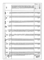
- the measurement data of the primary injection time is displayed as a list with numerical values on the monitor unit 6 for each shot, as shown in FIG.
- the mold opening time is not affected by the suitability of the molding conditions set in the molding condition setting means 30, and there are abnormalities in various servo motors provided in the molding machine body 10, or peripheral devices Variation occurs when temporal variation occurs in the operation process. Therefore, it is possible to estimate the occurrence of abnormality in various servo motors and peripheral devices by calculating the variation in mold opening time. Therefore, in the present embodiment, the mold opening time data is continuously taken into the storage unit 4 over a predetermined number of shots (for example, 50 shots or 100 shots), and the maximum value and the minimum value of the fetched mold opening time data are set. The deviation is obtained by the calculation unit 3.
- the monitor 6 determines that there is a variation in the mold opening time. Display a message.
- an explanatory note “Please check the state of the molding machine and peripheral machine” is displayed on the monitor unit 6.
- the mold opening time measurement data is displayed as a list with numerical values on the monitor unit 6 for each shot, as shown in FIG. FIG. 4 shows measurement data of the mold opening time at normal time. As is apparent from this figure, the mold opening time is very stable at normal time.
- the mold closing time is not affected by the suitability of the molding conditions set in the molding condition setting means 30, and there are abnormalities in various servo motors provided in the molding machine body 10 or when peripheral devices are Variation occurs when temporal variation occurs in the operation process. Therefore, by calculating the variation in mold closing time, it is possible to estimate the occurrence of abnormality in various servo motors and peripheral devices. Therefore, in the present embodiment, the mold closing time data is continuously taken into the storage unit 4 over a predetermined number of shots (for example, 50 shots or 100 shots), and the maximum value and the minimum value of the fetched mold closing time data are set. The deviation is obtained by the calculation unit 3.
- the monitor unit 6 determines that “the mold closing time varies”. Display a message.
- an explanatory note “Please check the state of the molding machine and peripheral machine” is displayed on the monitor unit 6.
- the operator can easily recognize that the mold closing time is more than the reference value and can quickly take an appropriate countermeasure. Accordingly, since the operation of the molding machine main body 10 can be stabilized as a total, a molded product having a target quality can be manufactured in a target shot cycle.
- the molded product take-out time is not affected by the suitability of the molding conditions set in the molding condition setting means 30, and there are abnormalities in various servo motors provided in the molding machine body 10, or peripheral devices. Variation occurs when there is a temporal variation in the process of operating. Therefore, it is possible to estimate the occurrence of abnormalities in various servo motors and peripheral devices by calculating the variation in the molded product removal time. Therefore, in the present embodiment, the molded product take-out time data is continuously taken into the storage unit 4 over a predetermined number of shots (for example, 50 shots or 100 shots), and the maximum value and the minimum of the taken-in molded product take-out time data are minimum.
- a predetermined number of shots for example, 50 shots or 100 shots
- the value deviation is obtained by the calculation unit 3.
- a reference value of the deviation of the molded article take-out time for example, 0.1 sec or more, as shown in FIG. Display a judgment message.
- an explanatory note “Please check the state of the molding machine and peripheral machine” is displayed on the monitor unit 6.
- the operator can easily recognize that the mold closing time is more than the reference value and can quickly take an appropriate countermeasure. Accordingly, since the operation of the molding machine main body 10 can be stabilized as a total, a molded product having a target quality can be manufactured in a target shot cycle.
- the mold temperature and molding material temperature are not stable, so there is some variation in the measured data of the filling pressure, but after that, the filling pressure is measured as the number of shots increases.
- the value data becomes stable. Therefore, for the filling pressure, even if the measured value data varies, it is not appropriate to take immediate measures, and the measured value data varies depending on the mold temperature or molding material temperature immediately after the start of continuous automatic operation. It is necessary to check whether it is based on instability. Therefore, in the present embodiment, filling pressure data for each measurement time from the start of injection to the end of injection is continuously taken into the storage unit 4 over a predetermined number of shots (for example, 50 shots or 100 shots).
- the filling pressure data taken into the storage unit 4 has a waveform as shown in FIG. 5 when an image is displayed on the monitor unit 5.
- the computing unit 3 obtains a deviation e between the maximum value and the minimum value of the filling pressure data for each measurement time from the start of injection to the end of injection based on the filling pressure data taken into the storage unit 4.
- a determination message “resin pressure state is changing” is displayed on the monitor unit 6 as shown in FIG.
- an explanatory note “The pressure value is changing and needs to be diagnosed again” is displayed on the monitor unit 6.
- the operator can easily recognize that there is a variation in the filling pressure that exceeds the reference value, and the re-diagnosis causes the variation to be instability in the mold temperature and molding material temperature immediately after the start of continuous automatic operation. Since it can be confirmed whether it is based, unnecessary confirmation work and maintenance can be avoided, and the productivity of the molding machine body 10 as a whole can be increased.
- the measured value data of the metering motor torque varies to some extent because the heating cylinder temperature is not stable, but thereafter the measured value data of the metering motor torque as the number of shots increases. Becomes stable. Therefore, as with the filling motor (primary pressure), even if the measured value data varies, it is not appropriate to take a countermeasure immediately, and the measured value data varies continuously and automatically. It is necessary to confirm whether or not this is based on instability of the heating cylinder temperature immediately after the start of the operation.
- metering motor torque data for each measurement time from the start of measurement to the end of measurement is continuously taken into the storage unit 4 over a predetermined number of shots (for example, 50 shots or 100 shots).
- the metering motor torque data taken into the storage unit 4 has a waveform as shown in FIG. 6 when the monitor unit 5 displays an image.
- the calculation unit 3 obtains a deviation e between the maximum value and the minimum value of the weighing motor torque data for each measurement time from the start of measurement to the end of measurement, based on the measurement motor torque data taken into the storage unit 4.
- a determination message “Measuring motor torque is changing” is displayed on the monitor unit 6 as shown in FIG.
- the screw retraction speed data for each measurement time from the start of measurement to the end of measurement is continuously taken into the storage unit 4 over a predetermined number of shots (for example, 50 shots or 100 shots).
- the screw retraction speed data taken into the storage unit 4 has a waveform as shown in FIG.
- the calculation unit 3 obtains a deviation e between the maximum value and the minimum value of the screw reverse speed data for each measurement time from the start of measurement to the end of measurement based on the reverse speed data of the screw taken into the storage unit 4.
- a determination message “Screw reverse speed is changing” is displayed on the monitor unit 6 as shown in FIG. .
- the control unit 30 performs the measurement. Since a unique determination display corresponding to the type of value is output to the monitor unit 6, the operator can reliably recognize the operational stability of the molding machine body 10. Further, even when the determination unit 5 determines that the variation in the operation of the molding machine main body 10 is larger than the reference value, the operator can quickly take an appropriate response, so that a non-defective product is manufactured with high efficiency. be able to.
- the gist of the present invention is not limited to this, and other matters can be diagnosed as appropriate.
Abstract
Provided is a molding diagnosis device for continuously diagnosing the operational stability of a molding machine detected during continuous automatic operation and reporting necessary messages to the operator by displaying same on a display device. In addition to setting nozzle temperature as a diagnostic category for operational stability of the molding machine body (10) in a storage unit (4), a standard value for the deviation in nozzle temperature is stored as a diagnostic standard value. When an assessment unit (5) determines that the deviation between the maximum value and the minimum value for the nozzle temperature sampled over the number of shots set by the shot number-setting unit (60) is at or above the standard value for the nozzle temperature deviation set in the storage unit (4), character data that "there is variation in the nozzle temperature," which indicates that the deviation in nozzle temperature is greater than the standard value, is displayed on a monitor unit (6).
Description
本発明は、射出成形機やダイカストマシンなどの成形機に備えられる成形診断装置に係り、特に、連続自動運転中における成形機の動作の安定性を診断するものに関する。
The present invention relates to a molding diagnostic apparatus provided in a molding machine such as an injection molding machine or a die casting machine, and particularly relates to a machine that diagnoses the stability of the operation of the molding machine during continuous automatic operation.
射出成形機やダイカストマシンなどの成形機には、成形条件の設定を行う成形条件設定装置が付設されており、成形機の稼働に先立っては、この成形条件設定装置を操作して、成形品に応じた所要の成形条件を入力する必要がある。しかしながら、成形機の成形条件は多岐にわたるので、成形条件の設定には熟練を必要とし、非熟練者にとっては必要とする全ての設定項目について効率良く設定作業を行うことが困難である。このような成形条件設定作業の困難性を緩和するため、従来、成形条件を設定する際の操作を簡素化するための工夫や、設定値の変更のし忘れを防止するための工夫を加えた種々の成形条件設定装置が提案されている(例えば、特許文献1,2,3参照。)。
Molding machines such as injection molding machines and die casting machines are equipped with molding condition setting devices that set molding conditions. Prior to the operation of the molding machine, the molding condition setting device is operated to operate a molded product. It is necessary to input required molding conditions according to the conditions. However, since the molding conditions of the molding machine are diverse, skill is required to set the molding conditions, and it is difficult for an unskilled person to efficiently set all the setting items required. In order to alleviate the difficulty of setting molding conditions like this, conventionally, a device for simplifying the operation when setting the molding conditions and a device for preventing forgetting to change the set value have been added. Various molding condition setting devices have been proposed (see, for example, Patent Documents 1, 2, and 3).
しかしながら、特許文献1,2,3に記載の成形条件設定装置を備えた成形機であっても、誤って不適正な成形条件を設定したり、いくつかの成形条件を設定し忘れることも実際上あり得る。また、成形条件の設定は、オペレータが自己の経験に基づいて行うものであるので、場合によっては、成形機が推奨する適正値と異なる成形条件をあえて設定することもあり得る。このような理由により成形条件設定装置に不適正な成形条件が設定された場合にも、成形機の機械動作には直ちに影響がないので、オペレータの指示により成形機は連続自動運転を開始する。しかしながら、成形条件設定装置に設定された成形条件によっては、連続自動運転中における成形機の動作が不安定となり、目標の品質に達していない成形品が成形されたり、目標とするショットサイクルが得られないなどの不都合を生じる場合がある。
However, even with a molding machine equipped with the molding condition setting device described in Patent Documents 1, 2, and 3, it is actually possible to mistakenly set inappropriate molding conditions or forget to set some molding conditions. It can be above. Further, since the setting of the molding conditions is performed by the operator based on his / her own experience, the molding conditions different from the appropriate values recommended by the molding machine may be set in some cases. Even if an inappropriate molding condition is set in the molding condition setting device for such a reason, there is no immediate influence on the machine operation of the molding machine, so the molding machine starts a continuous automatic operation according to an instruction from the operator. However, depending on the molding conditions set in the molding condition setting device, the operation of the molding machine becomes unstable during continuous automatic operation, and a molded product that does not reach the target quality is molded, or the target shot cycle is obtained. Inconveniences such as inability to occur may occur.
近年の成形機には、各種のセンサ類が適所に備えられると共に、各センサ類の検出データをグラフ表示や一覧表示などの適宜の形式で表示する表示装置が備えられている。したがって、連続自動運転中における成形機各部の動作状態は、オペレータが表示装置に表示されたデータを見ることにより確認でき、成形機の動作安定性についても、複数ショット(成形サイクル)分のデータの変化を見ることにより確認できる。しかしながら、オペレータは、通常、複数台の成形機の操作を一人で担当するので、各成形機の表示装置に表示されたデータを確認し続けること、及び、複数ショット分のデータの変化が不適正なものであるか否かを迅速に判定することは実際上困難である。
In recent molding machines, various sensors are provided in place, and a display device that displays detection data of each sensor in an appropriate format such as a graph display or a list display is provided. Therefore, the operating state of each part of the molding machine during continuous automatic operation can be confirmed by looking at the data displayed on the display device by the operator, and the operational stability of the molding machine is also calculated for multiple shots (molding cycles). This can be confirmed by looking at the changes. However, since the operator is usually responsible for operating a plurality of molding machines alone, it is necessary to continue to check the data displayed on the display device of each molding machine, and the data change for multiple shots is inappropriate. It is practically difficult to quickly determine whether or not it is a problem.
本発明は、このような従来技術の不備を解決するためになされたものであり、その目的は、連続自動運転中に検出される成形機の動作安定性を継続的に診断し、表示装置に所要のメッセージを表示してオペレータに報知する成形診断装置を提供することにある。
The present invention has been made to solve such deficiencies in the prior art, and its purpose is to continuously diagnose the operational stability of the molding machine detected during continuous automatic operation, and to provide a display device. An object of the present invention is to provide a molding diagnostic apparatus for displaying a required message and notifying an operator.
本発明は、上述の課題を解決するため、金型の開閉装置と、該開閉装置により型締された金型内に成形材料を射出する射出装置とを備え、複数の工程からなる所定の成形サイクルを繰り返して所定の成形品を連続的に成形する成形機本体と、オペレータが前記成形機本体に対する成形条件の設定を行う成形条件設定手段と、前記成形条件設定手段に設定された成形条件設定値に基づいて前記成形機本体の駆動を制御する制御手段と、前記成形機本体の所定の部位に備えられ、前記成形機本体の動作状態に応じた測定値を測定して出力する測定手段と、を有する成形機に備えられ、連続自動運転中における前記成形機本体の動作安定性を判定してオペレータに報知する成形診断装置であって、前記動作安定性の判定基準となるショット数を設定するショット数設定部と、前記測定手段の測定値、及び、前記ショット数設定部に設定された前記ショット数の入力部と、前記成形機本体の動作安定性を判定するための基準値、及び、前記測定手段の測定値が記憶される記憶部と、前記記憶部に記憶された前記ショット数分の前記測定値の偏差を演算する演算部と、前記入力部への前記測定値の入力数が前記ショット数設定部に設定されたショット数に達したか否か、及び、前記ショット数分の前記測定値の偏差が前記記憶部に記憶された基準値以上であるか否かを判定する判定部と、所要のデータを所要の形式で表示するモニタ部を有し、前記判定部が、前記ショット数分の前記測定値の偏差は、前記記憶部に記憶された基準値以上であると判定したとき、前記制御手段が、前記測定値の種別に応じた特有の判定表示を前記モニタ部に出力することを特徴とする。
In order to solve the above-described problems, the present invention includes a mold opening / closing device and an injection device for injecting a molding material into a mold clamped by the opening / closing device, and a predetermined molding including a plurality of steps. A molding machine body that continuously molds a predetermined molded product by repeating a cycle, a molding condition setting means for an operator to set molding conditions for the molding machine body, and a molding condition setting set in the molding condition setting means Control means for controlling the driving of the molding machine main body based on the value, and measuring means provided in a predetermined part of the molding machine main body for measuring and outputting a measurement value according to the operating state of the molding machine main body, Is a molding diagnostic apparatus that determines the operational stability of the molding machine body during continuous automatic operation and notifies an operator of the molding diagnostic apparatus, and sets the number of shots that serves as a criterion for determining the operational stability. A shot number setting unit, a measurement value of the measurement unit, an input unit of the shot number set in the shot number setting unit, a reference value for determining the operational stability of the molding machine body, and A storage unit that stores measurement values of the measurement unit, a calculation unit that calculates a deviation of the measurement values for the number of shots stored in the storage unit, and the number of inputs of the measurement values to the input unit Determines whether or not the number of shots set in the shot number setting unit has reached the number of shots and whether or not the deviation of the measured value for the number of shots is equal to or greater than a reference value stored in the storage unit A determination unit; and a monitor unit that displays required data in a required format, wherein the determination unit has a deviation of the measured value for the number of shots equal to or greater than a reference value stored in the storage unit. When the determination is made, the control means The specific judgment display according to the type and outputs to the monitor unit.
前記成形機本体の診断項目としては、ノズル温度、1次射出時間、型開時間、型閉時間及び成形品の取り出し時間から選択される少なくとも1項目、充填圧力、計量モータトルク及び計量時におけるスクリュの後退速度等を記憶部に設定することができる。また、前記基準値としては、診断項目に応じて、ノズル温度の偏差の基準値、1次射出時間、型開時間、型閉時間及び成形品の取り出し時間に関する偏差の基準値、充填開始から充填終了までの測定時間毎の充填圧力の偏差の基準値、計量開始から計量終了までの測定時間毎の計量モータトルクの偏差の基準値、計量開始から計量終了までの測定時間毎のスクリュの後退速度の偏差の基準値を記憶することができる。
The diagnostic items of the molding machine main body include at least one item selected from nozzle temperature, primary injection time, mold opening time, mold closing time, and molded product removal time, filling pressure, metering motor torque, and screw during metering. Can be set in the storage unit. In addition, as the reference value, the reference value of the deviation of the nozzle temperature, the reference value of the deviation relating to the primary injection time, the mold opening time, the mold closing time and the removal time of the molded product, depending on the diagnosis item, filling from the start of filling Reference value for deviation of filling pressure for each measurement time until the end, reference value for deviation of weighing motor torque for each measurement time from the start of measurement to the end of measurement, Retreat speed of the screw for each measurement time from the start of measurement to the end of measurement The reference value of the deviation can be stored.
成形機本体の診断は、個々の診断項目について別個に行うこともできるし、連続自動運転中にオペレータから成形機本体の診断が指示されたとき、記憶部に設定された全ての診断項目について自動的に実行することもできる。
Diagnosis of the molding machine body can be performed separately for each diagnostic item, and when the diagnosis of the molding machine body is instructed by the operator during continuous automatic operation, all diagnostic items set in the storage unit are automatically It can also be executed automatically.
本発明の成形診断装置は、判定部がショット数分の測定値の偏差は記憶部に記憶された基準値以上であると判定したとき、制御手段が測定値の種別に応じた特有の判定表示をモニタ部に出力するので、オペレータが成形機本体の動作安定性を確実に認識することができる。よって、オペレータが適切な対応を迅速にとることが可能となり、良品を高能率に製造することができる。
In the molding diagnosis apparatus of the present invention, when the determination unit determines that the deviation of the measurement value for the number of shots is equal to or greater than the reference value stored in the storage unit, the control unit displays a specific determination display according to the type of measurement value Is output to the monitor unit, the operator can reliably recognize the operational stability of the molding machine body. Therefore, it becomes possible for an operator to take an appropriate response quickly, and a good product can be manufactured with high efficiency.
以下、本発明に係る成形診断装置の実施形態を、図を参照しながら説明する。なお、本発明の要旨は、以下の実施形態に限定されるものではなく、発明の趣旨に反しない範囲で他の構成の成形機に対しても容易に適用可能であることは勿論である。
Hereinafter, an embodiment of a molding diagnostic apparatus according to the present invention will be described with reference to the drawings. It should be noted that the gist of the present invention is not limited to the following embodiments, and it is needless to say that the gist of the present invention can be easily applied to molding machines having other configurations without departing from the spirit of the invention.
図1に示すように、実施形態に係る成形診断装置1は、センサ群(測定手段)11を備えた成形機本体10と、制御手段20と、成形条件設定手段30とから構成される成形機に付設され、連続自動運転中における成形機本体10の動作安定性を診断する。成形診断装置1には、起動スイッチ40と、成形機本体10の診断項目及び各診断項目に関する動作安定性の基準値を入力する入力装置50と、成形機本体10の動作安定性を演算する際のセンサ群11から出力される測定値データのサンプル数であるショット数を設定するショット数設定部60が付設される。
As shown in FIG. 1, the molding diagnostic apparatus 1 according to the embodiment includes a molding machine body 10 including a sensor group (measuring unit) 11, a control unit 20, and a molding condition setting unit 30. The operation stability of the molding machine body 10 during continuous automatic operation is diagnosed. The molding diagnostic apparatus 1 includes a start switch 40, an input device 50 for inputting a diagnostic item of the molding machine body 10 and a reference value of operational stability regarding each diagnostic item, and a calculation of the operational stability of the molding machine body 10. A shot number setting unit 60 is provided for setting the number of shots, which is the number of samples of measurement value data output from the sensor group 11.
成形機本体10は、金型の開閉装置と、型締された金型内に成形材料を射出する射出装置とを備え、計量工程、型閉工程、型締工程、射出工程、型開工程及び製品取り出し工程等からなる所定の成形サイクルを繰り返して所定の成形品を成形する。実施形態に係る成形機本体10は、プラスチック製品を成形する射出成形機又は軽金属製品を成形するダイカストマシンのいずれでも良い。センサ群11は、開閉装置及び射出装置の所定の部位に設置され、連続自動運転中の成形機本体10の運転状態に応じた適宜の測定値データを出力する。これらのセンサ群11から出力される測定値データは、成形診断装置1及び制御手段20に入力される。なお、成形機本体10の周囲には、製品取出し装置等の図示しない周辺機器も必要に応じて配置される。これら成形機本体10及び周辺機器の構成に関しては、公知に属する事項であり、かつ本発明の要旨でもないので、説明を省略する。
The molding machine main body 10 includes a mold opening / closing device and an injection device that injects a molding material into the clamped mold, and includes a metering process, a mold closing process, a mold clamping process, an injection process, a mold opening process, and A predetermined molded product is formed by repeating a predetermined molding cycle including a product removal step and the like. The molding machine body 10 according to the embodiment may be either an injection molding machine that molds plastic products or a die casting machine that molds light metal products. The sensor group 11 is installed in a predetermined part of the opening / closing device and the injection device, and outputs appropriate measurement value data according to the operating state of the molding machine body 10 during continuous automatic operation. The measurement value data output from these sensor groups 11 is input to the molding diagnostic apparatus 1 and the control means 20. A peripheral device (not shown) such as a product take-out device is also arranged around the molding machine body 10 as necessary. The configurations of the molding machine main body 10 and peripheral devices are known matters and are not the gist of the present invention.
制御手段20は、成形診断装置1、成形機本体10及び周辺機器の駆動全体を司るもので、成形条件設定手段30に設定された成形条件設定値と、成形機本体10のスペックによって定まる成形条件基準値と、センサ群11から出力される測定値データとに基づいて金型の開閉装置及び射出装置の駆動を制御し、上述した所定の成形サイクルを繰り返し実行する。
The control means 20 is responsible for overall driving of the molding diagnostic apparatus 1, the molding machine body 10, and peripheral devices, and molding conditions determined by the molding condition setting values set in the molding condition setting means 30 and the specifications of the molding machine body 10. Based on the reference value and the measured value data output from the sensor group 11, the driving of the mold opening / closing device and the injection device is controlled, and the predetermined molding cycle described above is repeatedly executed.
成形条件設定手段30は、成形機本体10の稼働開始前に、オペレータが、成形しようとする成形品の特性に合致した適宜の成形条件設定値を入力するもので、例えば特許文献1,2,3に記載されたものなど、公知に属する任意の成形条件設定装置を用いることができる。成形条件設定装置30に設定すべき成形条件は多岐に亘っており、例えば射出工程における1次圧設定、射出タイマ設定、保圧速度設定、保圧時間設定、計量工程における計量工程時間及びサックバック設定、型開閉工程における低圧型締、低圧型締トルク及び低圧型締時間等を挙げることができる。
The molding condition setting means 30 is for the operator to input an appropriate molding condition setting value that matches the characteristics of the molded product to be molded before the molding machine body 10 starts operation. Any molding condition setting device belonging to the public knowledge such as those described in No. 3 can be used. The molding conditions to be set in the molding condition setting device 30 are various. For example, primary pressure setting in the injection process, injection timer setting, pressure holding speed setting, pressure holding time setting, measuring process time in the measuring process, and suckback Examples include low pressure mold clamping, low pressure mold clamping torque, and low pressure mold clamping time in the setting and mold opening / closing process.
図1に示すように、成形診断装置1は、センサ群11から出力される測定値データ、制御手段20から出力される制御信号、起動スイッチ40から出力されるスイッチ信号、入力装置50に入力された診断項目データ、基準値データ及びオペレータに表示する判定メッセージ、ショット数設定部60に設定されたショット数データを取り込む入力部2を有している。また、成形診断装置1は、入力部に取り込まれた上述の各データを記憶する記憶部4と、ショット数設定部60に設定されたショット数に亘ってサンプリングされた測定値データの最大値と最小値の偏差を演算する演算部3を有している。さらに、成形診断装置1は、入力部2への測定値データの入力数がショット数設定部60に設定されたショット数に達したか否か、及び、演算部3により求められたショット数分の測定値データの偏差が記憶部4に記憶された基準値データよりも大きいか否かを判定する判定部5を備えている。加えて、成形診断装置1は、演算部3に記憶された各種のデータ及び判定部5の判定結果に応じた所要の判定メッセージを所定の形式で表示するモニタ部6と、所要のデータを所要の形式でモニタ部6に出力するモニタドライバ7を有している。なお、成形条件診断装置1は、上述の制御手段20及び成形条件設定手段30と一体に構成することもできる。
As shown in FIG. 1, the molding diagnostic apparatus 1 is input to the measured value data output from the sensor group 11, the control signal output from the control means 20, the switch signal output from the start switch 40, and the input device 50. The input unit 2 takes in the diagnostic item data, the reference value data, the determination message to be displayed to the operator, and the shot number data set in the shot number setting unit 60. In addition, the molding diagnosis apparatus 1 includes the storage unit 4 that stores the above-described data captured in the input unit, and the maximum value of the measurement value data sampled over the number of shots set in the shot number setting unit 60. It has the calculating part 3 which calculates the deviation of the minimum value. Further, the molding diagnostic apparatus 1 determines whether or not the number of measurement value data input to the input unit 2 has reached the number of shots set in the shot number setting unit 60 and the number of shots determined by the calculation unit 3. The determination unit 5 determines whether or not the deviation of the measured value data is larger than the reference value data stored in the storage unit 4. In addition, the molding diagnosis apparatus 1 includes a monitor unit 6 that displays various data stored in the calculation unit 3 and a required determination message according to the determination result of the determination unit 5 in a predetermined format, and the required data. The monitor driver 7 for outputting to the monitor unit 6 in the form of The molding condition diagnosis apparatus 1 can also be configured integrally with the above-described control unit 20 and molding condition setting unit 30.
成形診断装置1は、オペレータが起動スイッチ40を操作することによって起動され、記憶部4に記憶された各診断項目について、所定のショット数分の測定値データの偏差が記憶部4に記憶された基準値データよりも大きいか否かを自動的に判定し、所要の診断項目に関する成形診断を行う。即ち、図2に示すように、オペレータは、成形条件設定手段30に成形条件設定値を設定し、かつ制御手段20を起動して成形機本体10の連続自動運転を開始した後、起動スイッチ40を操作することによって、成形診断装置1を随時起動することができる。成形診断装置1が起動されると、記憶部4に記憶された動作プログラムにしたがって、記憶部4に予め設定されたショット数について測定値データのサンプリングが行われ、サンプリングされた測定値データに基づいて、予め設定された診断項目についての成形診断が判定部5によって自動的に実行される。そして、判定結果に応じた所定の判定メッセージが記憶部4から読み出され、モニタドライバ7から出力されて、モニタ部6に表示される。オペレータは、この判定メッセージを確認し、必要に応じて成形条件設定値の変更等の所要の対応手段をとることができる。
The molding diagnostic apparatus 1 is activated when the operator operates the activation switch 40, and for each diagnostic item stored in the storage unit 4, a deviation of measured value data for a predetermined number of shots is stored in the storage unit 4. It is automatically determined whether or not it is larger than the reference value data, and a molding diagnosis relating to a required diagnosis item is performed. That is, as shown in FIG. 2, the operator sets a molding condition setting value in the molding condition setting unit 30 and activates the control unit 20 to start continuous automatic operation of the molding machine body 10. By operating, the molding diagnostic apparatus 1 can be started at any time. When the molding diagnostic apparatus 1 is activated, the measurement value data is sampled for the number of shots preset in the storage unit 4 in accordance with the operation program stored in the storage unit 4, and based on the sampled measurement value data Thus, a molding diagnosis for a preset diagnostic item is automatically executed by the determination unit 5. A predetermined determination message corresponding to the determination result is read from the storage unit 4, output from the monitor driver 7, and displayed on the monitor unit 6. The operator can confirm the determination message and take necessary countermeasures such as changing the molding condition setting value as necessary.
なお、オペレータが判定メッセージの内容に関わりなく、成形条件設定値の変更等は不要であると判断する場合には、そのまま連続自動運転を続行することもできる。また、上述の成形診断は、成形診断装置1が起動されたとき、記憶部4に記憶された全ての診断項目についての成形診断を連続的に行うようにすることもできるし、オペレータにより選択された診断項目についての成形診断のみを選択的に行うようにすることもできる。
Note that if the operator determines that the change of the molding condition setting value is unnecessary regardless of the content of the determination message, the continuous automatic operation can be continued as it is. In addition, the above-described molding diagnosis can be performed continuously for all diagnostic items stored in the storage unit 4 when the molding diagnosis apparatus 1 is activated, or selected by the operator. It is also possible to selectively perform only the molding diagnosis for the diagnosis items.
図3に示すように、本例の成形診断装置1においては、診断項目として、ノズル温度、1次射出時間、型開時間、型閉時間及び成形品の取り出し時間から選択される少なくとも1項目、充填圧力(1次射出圧)、計量モータトルク及び計量時におけるスクリュの後退速度等を記憶部4に設定されている。また、前記基準値としては、診断項目に応じて、ノズル温度の偏差の基準値、1次射出時間、型開時間、型閉時間及び成形品の取り出し時間に関する偏差の基準値、充填開始から充填終了までの測定時間毎の充填圧力の偏差の基準値、計量開始から計量終了までの測定時間毎の計量モータトルクの偏差の基準値、計量開始から計量終了までの測定時間毎のスクリュの後退速度の偏差の基準値が記憶部4に記憶されている。なお、図3から明らかなように、各偏差の基準値として、良品を高能率に製造するために許容される許容範囲が設定される。
As shown in FIG. 3, in the molding diagnostic apparatus 1 of this example, at least one item selected from the nozzle temperature, the primary injection time, the mold opening time, the mold closing time, and the molded product take-out time as diagnostic items, Filling pressure (primary injection pressure), metering motor torque, screw retraction speed during metering, and the like are set in the storage unit 4. In addition, as the reference value, the reference value of the deviation of the nozzle temperature, the reference value of the deviation relating to the primary injection time, the mold opening time, the mold closing time and the removal time of the molded product, depending on the diagnosis item, filling from the start of filling Reference value for deviation of filling pressure for each measurement time until the end, reference value for deviation of weighing motor torque for each measurement time from the start of measurement to the end of measurement, Retreat speed of the screw for each measurement time from the start of measurement to the end of measurement Is stored in the storage unit 4. As is apparent from FIG. 3, an allowable range for manufacturing a non-defective product with high efficiency is set as a reference value for each deviation.
以下、判定部5によって行われる成形診断の具体例を、診断項目毎に説明する。
Hereinafter, a specific example of the molding diagnosis performed by the determination unit 5 will be described for each diagnosis item.
〈ノズル温度〉
射出装置に備えられる射出ノズルは、連続自動運転中に直接金型に接触するので、最も温度のばらつきを生じやすい。そして、ノズル温度が変動すると、金型のキャビティ内に射出される成形材料の粘度が変動するため、成形品の品質に悪影響を及ぼす虞がある。射出ノズルの温度制御には通常PID制御が用いられ、初期状態においては初期チューニングが施されているが、金型に応じて射出ノズルの種類を変更したり、スクリュのメンテナンスによって射出ノズル内の状態が変化した場合などには、PID制御のチューニングがずれることもある。そこで、本実施形態においては、所定ショット数(例えば50ショット或いは100ショット)に亘って、射出ノズルに備えられた温度センサから出力されるノズル温度データを記憶部4に連続的に取り込み、取り込まれたノズル温度データの最大値と最小値の偏差を演算部3にて求める。そして、求められた偏差がノズル温度の偏差の基準値、例えば5℃以上であった場合には、図3に示すように、モニタ部6に「ノズル温度にばらつきがあります」という判定メッセージを表示する。また、これに加えて、モニタ部6に「オートチューニング(ノズル)の必要があります」という説明文を表示する。これにより、オペレータは、ノズル温度に基準値以上のばらつきがあることを容易に認識できると共に、適切な対処方法を迅速にとることが可能になる。したがって、トータルとして成形機本体10の動作を安定化できるので、目標とする品質の成形品を目標とするショットサイクルで製造できる。 <Nozzle temperature>
Since the injection nozzle provided in the injection device directly contacts the mold during the continuous automatic operation, the temperature variation is most likely to occur. When the nozzle temperature fluctuates, the viscosity of the molding material injected into the mold cavity fluctuates, which may adversely affect the quality of the molded product. PID control is usually used for temperature control of the injection nozzle, and initial tuning is performed in the initial state. However, the state of the injection nozzle can be changed by changing the type of the injection nozzle according to the mold or by screw maintenance. When the value of PID changes, the tuning of PID control may shift. Therefore, in the present embodiment, nozzle temperature data output from the temperature sensor provided in the injection nozzle is continuously taken into thestorage unit 4 for a predetermined number of shots (for example, 50 shots or 100 shots). The deviation between the maximum value and the minimum value of the nozzle temperature data is obtained by the calculation unit 3. When the obtained deviation is a reference value of nozzle temperature deviation, for example, 5 ° C. or more, a determination message “nozzle temperature varies” is displayed on the monitor unit 6 as shown in FIG. To do. In addition to this, an explanatory note “auto tuning (nozzle required)” is displayed on the monitor unit 6. As a result, the operator can easily recognize that the nozzle temperature varies more than the reference value and can quickly take an appropriate countermeasure. Accordingly, since the operation of the molding machine main body 10 can be stabilized as a total, a molded product having a target quality can be manufactured in a target shot cycle.
射出装置に備えられる射出ノズルは、連続自動運転中に直接金型に接触するので、最も温度のばらつきを生じやすい。そして、ノズル温度が変動すると、金型のキャビティ内に射出される成形材料の粘度が変動するため、成形品の品質に悪影響を及ぼす虞がある。射出ノズルの温度制御には通常PID制御が用いられ、初期状態においては初期チューニングが施されているが、金型に応じて射出ノズルの種類を変更したり、スクリュのメンテナンスによって射出ノズル内の状態が変化した場合などには、PID制御のチューニングがずれることもある。そこで、本実施形態においては、所定ショット数(例えば50ショット或いは100ショット)に亘って、射出ノズルに備えられた温度センサから出力されるノズル温度データを記憶部4に連続的に取り込み、取り込まれたノズル温度データの最大値と最小値の偏差を演算部3にて求める。そして、求められた偏差がノズル温度の偏差の基準値、例えば5℃以上であった場合には、図3に示すように、モニタ部6に「ノズル温度にばらつきがあります」という判定メッセージを表示する。また、これに加えて、モニタ部6に「オートチューニング(ノズル)の必要があります」という説明文を表示する。これにより、オペレータは、ノズル温度に基準値以上のばらつきがあることを容易に認識できると共に、適切な対処方法を迅速にとることが可能になる。したがって、トータルとして成形機本体10の動作を安定化できるので、目標とする品質の成形品を目標とするショットサイクルで製造できる。 <Nozzle temperature>
Since the injection nozzle provided in the injection device directly contacts the mold during the continuous automatic operation, the temperature variation is most likely to occur. When the nozzle temperature fluctuates, the viscosity of the molding material injected into the mold cavity fluctuates, which may adversely affect the quality of the molded product. PID control is usually used for temperature control of the injection nozzle, and initial tuning is performed in the initial state. However, the state of the injection nozzle can be changed by changing the type of the injection nozzle according to the mold or by screw maintenance. When the value of PID changes, the tuning of PID control may shift. Therefore, in the present embodiment, nozzle temperature data output from the temperature sensor provided in the injection nozzle is continuously taken into the
〈1次射出時間〉
1次射出時間は、成形条件設定手段30に設定される成形条件の適否に左右されず、成形機本体10に備えられる各種サーボモータに異常がある場合や、周辺機器が動作する工程に時間的なばらつきを発生している場合にばらつきを生じる。したがって、1次射出時間のばらつきを演算することにより、各種サーボモータや周辺機器の異常発生を推定することができる。そこで、本実施形態においては、所定ショット数(例えば50ショット或いは100ショット)に亘って1次射出時間データを記憶部4に連続的に取り込み、取り込まれた1次射出時間データの最大値と最小値の偏差を演算部3にて求める。そして、求められた偏差が1次射出時間の偏差の基準値、例えば0.1sec以上であった場合には、図3に示すように、モニタ部6に「1次射出時間にばらつきがあります」という判定メッセージを表示する。また、これに加えて、モニタ部6に「成形機及び周辺機の状態を確認してください」という説明文を表示する。これにより、オペレータは、1次射出時間に基準値以上のばらつきがあることを容易に認識できると共に、適切な対処方法を迅速にとることが可能になる。したがって、トータルとして成形機本体10の動作を安定化できるので、目標とする品質の成形品を目標とするショットサイクルで製造できる。なお、1次射出時間の測定データは、図4に示すように、ショット毎にモニタ部6に数値をもって一覧表示される。 <Primary injection time>
The primary injection time is not affected by the suitability of the molding conditions set in the molding condition setting means 30, and there is an abnormality in various servo motors provided in themolding machine body 10 or the time when the peripheral device operates. Variation occurs when a large variation occurs. Therefore, by calculating the variation of the primary injection time, it is possible to estimate the occurrence of abnormality in various servo motors and peripheral devices. Therefore, in the present embodiment, primary injection time data is continuously taken into the storage unit 4 over a predetermined number of shots (for example, 50 shots or 100 shots), and the maximum value and minimum value of the taken primary injection time data are taken. The value deviation is obtained by the calculation unit 3. When the obtained deviation is a reference value of the deviation of the primary injection time, for example, 0.1 sec or more, as shown in FIG. 3, the monitor unit 6 “varies in the primary injection time” Is displayed. In addition, an explanatory note “Please check the state of the molding machine and peripheral machine” is displayed on the monitor unit 6. As a result, the operator can easily recognize that the primary injection time varies more than the reference value and can quickly take an appropriate countermeasure. Accordingly, since the operation of the molding machine main body 10 can be stabilized as a total, a molded product having a target quality can be manufactured in a target shot cycle. The measurement data of the primary injection time is displayed as a list with numerical values on the monitor unit 6 for each shot, as shown in FIG.
1次射出時間は、成形条件設定手段30に設定される成形条件の適否に左右されず、成形機本体10に備えられる各種サーボモータに異常がある場合や、周辺機器が動作する工程に時間的なばらつきを発生している場合にばらつきを生じる。したがって、1次射出時間のばらつきを演算することにより、各種サーボモータや周辺機器の異常発生を推定することができる。そこで、本実施形態においては、所定ショット数(例えば50ショット或いは100ショット)に亘って1次射出時間データを記憶部4に連続的に取り込み、取り込まれた1次射出時間データの最大値と最小値の偏差を演算部3にて求める。そして、求められた偏差が1次射出時間の偏差の基準値、例えば0.1sec以上であった場合には、図3に示すように、モニタ部6に「1次射出時間にばらつきがあります」という判定メッセージを表示する。また、これに加えて、モニタ部6に「成形機及び周辺機の状態を確認してください」という説明文を表示する。これにより、オペレータは、1次射出時間に基準値以上のばらつきがあることを容易に認識できると共に、適切な対処方法を迅速にとることが可能になる。したがって、トータルとして成形機本体10の動作を安定化できるので、目標とする品質の成形品を目標とするショットサイクルで製造できる。なお、1次射出時間の測定データは、図4に示すように、ショット毎にモニタ部6に数値をもって一覧表示される。 <Primary injection time>
The primary injection time is not affected by the suitability of the molding conditions set in the molding condition setting means 30, and there is an abnormality in various servo motors provided in the
〈型開時間〉
型開時間も1次射出時間と同様に、成形条件設定手段30に設定される成形条件の適否に左右されず、成形機本体10に備えられる各種サーボモータに異常がある場合や、周辺機器が動作する工程に時間的なばらつきを発生している場合にばらつきを生じる。したがって、型開時間のばらつきを演算することにより、各種サーボモータや周辺機器の異常発生を推定することができる。そこで、本実施形態においては、所定ショット数(例えば50ショット或いは100ショット)に亘って型開時間データを記憶部4に連続的に取り込み、取り込まれた型開時間データの最大値と最小値の偏差を演算部3にて求める。そして、求められた偏差が型開時間の偏差の基準値、例えば0.1sec以上であった場合には、図3に示すように、モニタ部6に「型開時間にばらつきがあります」という判定メッセージを表示する。また、これに加えて、モニタ部6に「成形機及び周辺機の状態を確認してください」という説明文を表示する。これにより、オペレータは、型開時間に基準値以上のばらつきがあることを容易に認識できると共に、適切な対処方法を迅速にとることが可能になる。したがって、トータルとして成形機本体10の動作を安定化できるので、目標とする品質の成形品を目標とするショットサイクルで製造できる。なお、型開時間の測定データは、図4に示すように、ショット毎にモニタ部6に数値をもって一覧表示される。図4は正常時における型開時間の測定データを示しており、この図から明らかなように、正常時において型開時間は非常に安定している。 <Mold opening time>
Similarly to the primary injection time, the mold opening time is not affected by the suitability of the molding conditions set in the molding condition setting means 30, and there are abnormalities in various servo motors provided in themolding machine body 10, or peripheral devices Variation occurs when temporal variation occurs in the operation process. Therefore, it is possible to estimate the occurrence of abnormality in various servo motors and peripheral devices by calculating the variation in mold opening time. Therefore, in the present embodiment, the mold opening time data is continuously taken into the storage unit 4 over a predetermined number of shots (for example, 50 shots or 100 shots), and the maximum value and the minimum value of the fetched mold opening time data are set. The deviation is obtained by the calculation unit 3. When the obtained deviation is a reference value of the deviation of the mold opening time, for example, 0.1 sec or more, as shown in FIG. 3, the monitor 6 determines that there is a variation in the mold opening time. Display a message. In addition, an explanatory note “Please check the state of the molding machine and peripheral machine” is displayed on the monitor unit 6. As a result, the operator can easily recognize that the mold opening time is more than the reference value and can quickly take an appropriate countermeasure. Accordingly, since the operation of the molding machine main body 10 can be stabilized as a total, a molded product having a target quality can be manufactured in a target shot cycle. The mold opening time measurement data is displayed as a list with numerical values on the monitor unit 6 for each shot, as shown in FIG. FIG. 4 shows measurement data of the mold opening time at normal time. As is apparent from this figure, the mold opening time is very stable at normal time.
型開時間も1次射出時間と同様に、成形条件設定手段30に設定される成形条件の適否に左右されず、成形機本体10に備えられる各種サーボモータに異常がある場合や、周辺機器が動作する工程に時間的なばらつきを発生している場合にばらつきを生じる。したがって、型開時間のばらつきを演算することにより、各種サーボモータや周辺機器の異常発生を推定することができる。そこで、本実施形態においては、所定ショット数(例えば50ショット或いは100ショット)に亘って型開時間データを記憶部4に連続的に取り込み、取り込まれた型開時間データの最大値と最小値の偏差を演算部3にて求める。そして、求められた偏差が型開時間の偏差の基準値、例えば0.1sec以上であった場合には、図3に示すように、モニタ部6に「型開時間にばらつきがあります」という判定メッセージを表示する。また、これに加えて、モニタ部6に「成形機及び周辺機の状態を確認してください」という説明文を表示する。これにより、オペレータは、型開時間に基準値以上のばらつきがあることを容易に認識できると共に、適切な対処方法を迅速にとることが可能になる。したがって、トータルとして成形機本体10の動作を安定化できるので、目標とする品質の成形品を目標とするショットサイクルで製造できる。なお、型開時間の測定データは、図4に示すように、ショット毎にモニタ部6に数値をもって一覧表示される。図4は正常時における型開時間の測定データを示しており、この図から明らかなように、正常時において型開時間は非常に安定している。 <Mold opening time>
Similarly to the primary injection time, the mold opening time is not affected by the suitability of the molding conditions set in the molding condition setting means 30, and there are abnormalities in various servo motors provided in the
〈型閉時間〉
型閉時間も1次射出時間と同様に、成形条件設定手段30に設定される成形条件の適否に左右されず、成形機本体10に備えられる各種サーボモータに異常がある場合や、周辺機器が動作する工程に時間的なばらつきを発生している場合にばらつきを生じる。したがって、型閉時間のばらつきを演算することにより、各種サーボモータや周辺機器の異常発生を推定することができる。そこで、本実施形態においては、所定ショット数(例えば50ショット或いは100ショット)に亘って型閉時間データを記憶部4に連続的に取り込み、取り込まれた型閉時間データの最大値と最小値の偏差を演算部3にて求める。そして、求められた偏差が型閉時間の偏差の基準値、例えば0.1sec以上であった場合には、図3に示すように、モニタ部6に「型閉時間にばらつきがあります」という判定メッセージを表示する。また、これに加えて、モニタ部6に「成形機及び周辺機の状態を確認してください」という説明文を表示する。これにより、オペレータは、型閉時間に基準値以上のばらつきがあることを容易に認識できると共に、適切な対処方法を迅速にとることが可能になる。したがって、トータルとして成形機本体10の動作を安定化できるので、目標とする品質の成形品を目標とするショットサイクルで製造できる。 <Mold closing time>
Similarly to the primary injection time, the mold closing time is not affected by the suitability of the molding conditions set in the molding condition setting means 30, and there are abnormalities in various servo motors provided in themolding machine body 10 or when peripheral devices are Variation occurs when temporal variation occurs in the operation process. Therefore, by calculating the variation in mold closing time, it is possible to estimate the occurrence of abnormality in various servo motors and peripheral devices. Therefore, in the present embodiment, the mold closing time data is continuously taken into the storage unit 4 over a predetermined number of shots (for example, 50 shots or 100 shots), and the maximum value and the minimum value of the fetched mold closing time data are set. The deviation is obtained by the calculation unit 3. If the obtained deviation is a reference value of the mold closing time deviation, for example, 0.1 sec or more, as shown in FIG. 3, the monitor unit 6 determines that “the mold closing time varies”. Display a message. In addition, an explanatory note “Please check the state of the molding machine and peripheral machine” is displayed on the monitor unit 6. As a result, the operator can easily recognize that the mold closing time is more than the reference value and can quickly take an appropriate countermeasure. Accordingly, since the operation of the molding machine main body 10 can be stabilized as a total, a molded product having a target quality can be manufactured in a target shot cycle.
型閉時間も1次射出時間と同様に、成形条件設定手段30に設定される成形条件の適否に左右されず、成形機本体10に備えられる各種サーボモータに異常がある場合や、周辺機器が動作する工程に時間的なばらつきを発生している場合にばらつきを生じる。したがって、型閉時間のばらつきを演算することにより、各種サーボモータや周辺機器の異常発生を推定することができる。そこで、本実施形態においては、所定ショット数(例えば50ショット或いは100ショット)に亘って型閉時間データを記憶部4に連続的に取り込み、取り込まれた型閉時間データの最大値と最小値の偏差を演算部3にて求める。そして、求められた偏差が型閉時間の偏差の基準値、例えば0.1sec以上であった場合には、図3に示すように、モニタ部6に「型閉時間にばらつきがあります」という判定メッセージを表示する。また、これに加えて、モニタ部6に「成形機及び周辺機の状態を確認してください」という説明文を表示する。これにより、オペレータは、型閉時間に基準値以上のばらつきがあることを容易に認識できると共に、適切な対処方法を迅速にとることが可能になる。したがって、トータルとして成形機本体10の動作を安定化できるので、目標とする品質の成形品を目標とするショットサイクルで製造できる。 <Mold closing time>
Similarly to the primary injection time, the mold closing time is not affected by the suitability of the molding conditions set in the molding condition setting means 30, and there are abnormalities in various servo motors provided in the
〈成形品取り出し時間〉
成形品取り出し時間も1次射出時間と同様に、成形条件設定手段30に設定される成形条件の適否に左右されず、成形機本体10に備えられる各種サーボモータに異常がある場合や、周辺機器が動作する工程に時間的なばらつきを発生している場合にばらつきを生じる。したがって、成形品取り出し時間のばらつきを演算することにより、各種サーボモータや周辺機器の異常発生を推定することができる。そこで、本実施形態においては、所定ショット数(例えば50ショット或いは100ショット)に亘って成形品取り出し時間データを記憶部4に連続的に取り込み、取り込まれた成形品取り出し時間データの最大値と最小値の偏差を演算部3にて求める。そして、求められた偏差が成形品取り出し時間の偏差の基準値、例えば0.1sec以上であった場合には、図3に示すように、モニタ部6に「型閉時間にばらつきがあります」という判定メッセージを表示する。また、これに加えて、モニタ部6に「成形機及び周辺機の状態を確認してください」という説明文を表示する。これにより、オペレータは、型閉時間に基準値以上のばらつきがあることを容易に認識できると共に、適切な対処方法を迅速にとることが可能になる。したがって、トータルとして成形機本体10の動作を安定化できるので、目標とする品質の成形品を目標とするショットサイクルで製造できる。 <Molded product removal time>
Similarly to the primary injection time, the molded product take-out time is not affected by the suitability of the molding conditions set in the molding condition setting means 30, and there are abnormalities in various servo motors provided in themolding machine body 10, or peripheral devices. Variation occurs when there is a temporal variation in the process of operating. Therefore, it is possible to estimate the occurrence of abnormalities in various servo motors and peripheral devices by calculating the variation in the molded product removal time. Therefore, in the present embodiment, the molded product take-out time data is continuously taken into the storage unit 4 over a predetermined number of shots (for example, 50 shots or 100 shots), and the maximum value and the minimum of the taken-in molded product take-out time data are minimum. The value deviation is obtained by the calculation unit 3. When the obtained deviation is a reference value of the deviation of the molded article take-out time, for example, 0.1 sec or more, as shown in FIG. Display a judgment message. In addition, an explanatory note “Please check the state of the molding machine and peripheral machine” is displayed on the monitor unit 6. As a result, the operator can easily recognize that the mold closing time is more than the reference value and can quickly take an appropriate countermeasure. Accordingly, since the operation of the molding machine main body 10 can be stabilized as a total, a molded product having a target quality can be manufactured in a target shot cycle.
成形品取り出し時間も1次射出時間と同様に、成形条件設定手段30に設定される成形条件の適否に左右されず、成形機本体10に備えられる各種サーボモータに異常がある場合や、周辺機器が動作する工程に時間的なばらつきを発生している場合にばらつきを生じる。したがって、成形品取り出し時間のばらつきを演算することにより、各種サーボモータや周辺機器の異常発生を推定することができる。そこで、本実施形態においては、所定ショット数(例えば50ショット或いは100ショット)に亘って成形品取り出し時間データを記憶部4に連続的に取り込み、取り込まれた成形品取り出し時間データの最大値と最小値の偏差を演算部3にて求める。そして、求められた偏差が成形品取り出し時間の偏差の基準値、例えば0.1sec以上であった場合には、図3に示すように、モニタ部6に「型閉時間にばらつきがあります」という判定メッセージを表示する。また、これに加えて、モニタ部6に「成形機及び周辺機の状態を確認してください」という説明文を表示する。これにより、オペレータは、型閉時間に基準値以上のばらつきがあることを容易に認識できると共に、適切な対処方法を迅速にとることが可能になる。したがって、トータルとして成形機本体10の動作を安定化できるので、目標とする品質の成形品を目標とするショットサイクルで製造できる。 <Molded product removal time>
Similarly to the primary injection time, the molded product take-out time is not affected by the suitability of the molding conditions set in the molding condition setting means 30, and there are abnormalities in various servo motors provided in the
〈充填圧力(1次圧)〉
連続自動運転の開始直後においては、金型温度や成形材料温度が安定していないために充填圧力の測定値データにある程度のばらつきが生じるが、その後はショット数の増加に伴って充填圧力の測定値データが安定してくる。したがって、充填圧力については、測定値データにばらつきが生じたとしても、直ちに対応策をとることは適切ではなく、測定値データのばらつきが連続自動運転の開始直後における金型温度や成形材料温度の不安定さに基づくものかどうかを確認する必要がある。そこで、本実施形態においては、所定ショット数(例えば50ショット或いは100ショット)に亘って、射出開始から射出終了までの測定時間毎の充填圧力データを記憶部4に連続的に取り込む。記憶部4に取り込まれた充填圧力データは、モニタ部5に画像表示した場合、図5に示すような波形となる。演算部3は、記憶部4に取り込まれた充填圧力データに基づいて、射出開始から射出終了までの測定時間毎の充填圧力データの最大値と最小値の偏差eを求める。そして、求められた偏差が充填圧力の偏差の基準値以上であった場合には、図3に示すように、モニタ部6に「樹脂圧状態が変動中です」という判定メッセージを表示する。また、これに加えて、モニタ部6に「圧力値が変動中です 再度診断の必要性があります」という説明文を表示する。これにより、オペレータは、充填圧力に基準値以上のばらつきがあることを容易に認識できると共に、再度の診断によってそのばらつきが連続自動運転の開始直後における金型温度や成形材料温度の不安定さに基づくものかどうかを確認できるので、無用な確認作業やメンテナンスを回避することができて、トータルとしての成形機本体10の生産性を高めることができる。 <Filling pressure (primary pressure)>
Immediately after the start of continuous automatic operation, the mold temperature and molding material temperature are not stable, so there is some variation in the measured data of the filling pressure, but after that, the filling pressure is measured as the number of shots increases. The value data becomes stable. Therefore, for the filling pressure, even if the measured value data varies, it is not appropriate to take immediate measures, and the measured value data varies depending on the mold temperature or molding material temperature immediately after the start of continuous automatic operation. It is necessary to check whether it is based on instability. Therefore, in the present embodiment, filling pressure data for each measurement time from the start of injection to the end of injection is continuously taken into thestorage unit 4 over a predetermined number of shots (for example, 50 shots or 100 shots). The filling pressure data taken into the storage unit 4 has a waveform as shown in FIG. 5 when an image is displayed on the monitor unit 5. The computing unit 3 obtains a deviation e between the maximum value and the minimum value of the filling pressure data for each measurement time from the start of injection to the end of injection based on the filling pressure data taken into the storage unit 4. When the obtained deviation is equal to or larger than the reference value of the filling pressure deviation, a determination message “resin pressure state is changing” is displayed on the monitor unit 6 as shown in FIG. In addition to this, an explanatory note “The pressure value is changing and needs to be diagnosed again” is displayed on the monitor unit 6. As a result, the operator can easily recognize that there is a variation in the filling pressure that exceeds the reference value, and the re-diagnosis causes the variation to be instability in the mold temperature and molding material temperature immediately after the start of continuous automatic operation. Since it can be confirmed whether it is based, unnecessary confirmation work and maintenance can be avoided, and the productivity of the molding machine body 10 as a whole can be increased.
連続自動運転の開始直後においては、金型温度や成形材料温度が安定していないために充填圧力の測定値データにある程度のばらつきが生じるが、その後はショット数の増加に伴って充填圧力の測定値データが安定してくる。したがって、充填圧力については、測定値データにばらつきが生じたとしても、直ちに対応策をとることは適切ではなく、測定値データのばらつきが連続自動運転の開始直後における金型温度や成形材料温度の不安定さに基づくものかどうかを確認する必要がある。そこで、本実施形態においては、所定ショット数(例えば50ショット或いは100ショット)に亘って、射出開始から射出終了までの測定時間毎の充填圧力データを記憶部4に連続的に取り込む。記憶部4に取り込まれた充填圧力データは、モニタ部5に画像表示した場合、図5に示すような波形となる。演算部3は、記憶部4に取り込まれた充填圧力データに基づいて、射出開始から射出終了までの測定時間毎の充填圧力データの最大値と最小値の偏差eを求める。そして、求められた偏差が充填圧力の偏差の基準値以上であった場合には、図3に示すように、モニタ部6に「樹脂圧状態が変動中です」という判定メッセージを表示する。また、これに加えて、モニタ部6に「圧力値が変動中です 再度診断の必要性があります」という説明文を表示する。これにより、オペレータは、充填圧力に基準値以上のばらつきがあることを容易に認識できると共に、再度の診断によってそのばらつきが連続自動運転の開始直後における金型温度や成形材料温度の不安定さに基づくものかどうかを確認できるので、無用な確認作業やメンテナンスを回避することができて、トータルとしての成形機本体10の生産性を高めることができる。 <Filling pressure (primary pressure)>
Immediately after the start of continuous automatic operation, the mold temperature and molding material temperature are not stable, so there is some variation in the measured data of the filling pressure, but after that, the filling pressure is measured as the number of shots increases. The value data becomes stable. Therefore, for the filling pressure, even if the measured value data varies, it is not appropriate to take immediate measures, and the measured value data varies depending on the mold temperature or molding material temperature immediately after the start of continuous automatic operation. It is necessary to check whether it is based on instability. Therefore, in the present embodiment, filling pressure data for each measurement time from the start of injection to the end of injection is continuously taken into the
〈計量モータトルク〉
連続自動運転の開始直後においては、加熱シリンダ温度が安定していないために計量モータトルクの測定値データにある程度のばらつきが生じるが、その後はショット数の増加に伴って計量モータトルクの測定値データが安定してくる。したがって、計量モータトルクについても、充填圧力(1次圧)と同様に、測定値データにばらつきが生じたとしても、直ちに対応策をとることは適切ではなく、測定値データのばらつきが連続自動運転の開始直後における加熱シリンダ温度の不安定さに基づくものかどうかを確認する必要がある。そこで、本実施形態においては、所定ショット数(例えば50ショット或いは100ショット)に亘って、計量開始から計量終了までの測定時間毎の計量モータトルクデータを記憶部4に連続的に取り込む。記憶部4に取り込まれた計量モータトルクデータは、モニタ部5に画像表示した場合、図6に示すような波形となる。演算部3は、記憶部4に取り込まれた計量モータトルクデータに基づいて、計量開始から計量終了までの測定時間毎の計量モータトルクデータの最大値と最小値の偏差eを求める。そして、求められた偏差が計量モータトルクの偏差の基準値以上であった場合には、図3に示すように、モニタ部6に「計量モータトルクが変動中です」という判定メッセージを表示する。また、これに加えて、モニタ部6に「計量モータトルクが変動中です 再度診断の必要性があります」という説明文を表示する。これにより、オペレータは、計量モータトルクに基準値以上のばらつきがあることを容易に認識できると共に、再度の診断によってそのばらつきが連続自動運転の開始直後における加熱シリンダ温度の不安定さに基づくものかどうかを確認できるので、無用な確認作業やメンテナンスを回避することができて、トータルとしての成形機本体10の生産性を高めることができる。 <Weighing motor torque>
Immediately after the start of continuous automatic operation, the measured value data of the metering motor torque varies to some extent because the heating cylinder temperature is not stable, but thereafter the measured value data of the metering motor torque as the number of shots increases. Becomes stable. Therefore, as with the filling motor (primary pressure), even if the measured value data varies, it is not appropriate to take a countermeasure immediately, and the measured value data varies continuously and automatically. It is necessary to confirm whether or not this is based on instability of the heating cylinder temperature immediately after the start of the operation. Therefore, in the present embodiment, metering motor torque data for each measurement time from the start of measurement to the end of measurement is continuously taken into thestorage unit 4 over a predetermined number of shots (for example, 50 shots or 100 shots). The metering motor torque data taken into the storage unit 4 has a waveform as shown in FIG. 6 when the monitor unit 5 displays an image. The calculation unit 3 obtains a deviation e between the maximum value and the minimum value of the weighing motor torque data for each measurement time from the start of measurement to the end of measurement, based on the measurement motor torque data taken into the storage unit 4. When the obtained deviation is equal to or larger than the reference value of the deviation of the metering motor torque, a determination message “Measuring motor torque is changing” is displayed on the monitor unit 6 as shown in FIG. In addition to this, an explanatory note “Weighing motor torque is fluctuating and needs to be diagnosed again” is displayed on the monitor 6. As a result, the operator can easily recognize that there is a variation exceeding the reference value in the metering motor torque, and whether the variation is based on the instability of the heating cylinder temperature immediately after the start of continuous automatic operation by re-diagnosis. Since it can be confirmed, unnecessary confirmation work and maintenance can be avoided, and the productivity of the molding machine body 10 as a whole can be increased.
連続自動運転の開始直後においては、加熱シリンダ温度が安定していないために計量モータトルクの測定値データにある程度のばらつきが生じるが、その後はショット数の増加に伴って計量モータトルクの測定値データが安定してくる。したがって、計量モータトルクについても、充填圧力(1次圧)と同様に、測定値データにばらつきが生じたとしても、直ちに対応策をとることは適切ではなく、測定値データのばらつきが連続自動運転の開始直後における加熱シリンダ温度の不安定さに基づくものかどうかを確認する必要がある。そこで、本実施形態においては、所定ショット数(例えば50ショット或いは100ショット)に亘って、計量開始から計量終了までの測定時間毎の計量モータトルクデータを記憶部4に連続的に取り込む。記憶部4に取り込まれた計量モータトルクデータは、モニタ部5に画像表示した場合、図6に示すような波形となる。演算部3は、記憶部4に取り込まれた計量モータトルクデータに基づいて、計量開始から計量終了までの測定時間毎の計量モータトルクデータの最大値と最小値の偏差eを求める。そして、求められた偏差が計量モータトルクの偏差の基準値以上であった場合には、図3に示すように、モニタ部6に「計量モータトルクが変動中です」という判定メッセージを表示する。また、これに加えて、モニタ部6に「計量モータトルクが変動中です 再度診断の必要性があります」という説明文を表示する。これにより、オペレータは、計量モータトルクに基準値以上のばらつきがあることを容易に認識できると共に、再度の診断によってそのばらつきが連続自動運転の開始直後における加熱シリンダ温度の不安定さに基づくものかどうかを確認できるので、無用な確認作業やメンテナンスを回避することができて、トータルとしての成形機本体10の生産性を高めることができる。 <Weighing motor torque>
Immediately after the start of continuous automatic operation, the measured value data of the metering motor torque varies to some extent because the heating cylinder temperature is not stable, but thereafter the measured value data of the metering motor torque as the number of shots increases. Becomes stable. Therefore, as with the filling motor (primary pressure), even if the measured value data varies, it is not appropriate to take a countermeasure immediately, and the measured value data varies continuously and automatically. It is necessary to confirm whether or not this is based on instability of the heating cylinder temperature immediately after the start of the operation. Therefore, in the present embodiment, metering motor torque data for each measurement time from the start of measurement to the end of measurement is continuously taken into the
〈計量時におけるスクリュの後退速度〉
連続自動運転の開始直後においては、加熱シリンダ温度が安定していないために計量時におけるスクリュの後退速度の測定値データにある程度のばらつきが生じるが、その後はショット数の増加に伴ってスクリュの後退速度の測定値データが安定してくる。したがって、スクリュの後退速度についても、計量モータトルクと同様に、測定値データにばらつきが生じたとしても、直ちに対応策をとることは適切ではなく、測定値データのばらつきが連続自動運転の開始直後における加熱シリンダ温度の不安定さに基づくものかどうかを確認する必要がある。そこで、本実施形態においては、所定ショット数(例えば50ショット或いは100ショット)に亘って、計量開始から計量終了までの測定時間毎のスクリュの後退速度データを記憶部4に連続的に取り込む。記憶部4に取り込まれたスクリュの後退速度データは、モニタ部5に画像表示した場合、図6に示すような波形となる。演算部3は、記憶部4に取り込まれたスクリュの後退速度データに基づいて、計量開始から計量終了までの測定時間毎のスクリュの後退速度データの最大値と最小値の偏差eを求める。そして、求められた偏差がスクリュの後退速度の偏差の基準値以上であった場合には、図3に示すように、モニタ部6に「スクリュ後退速度が変動中です」という判定メッセージを表示する。また、これに加えて、モニタ部6に「スクリュの後退速度が変動中です 再度診断の必要性があります」という説明文を表示する。これにより、オペレータは、スクリュの後退速度に基準値以上のばらつきがあることを容易に認識できると共に、再度の診断によってそのばらつきが連続自動運転の開始直後における加熱シリンダ温度の不安定さに基づくものかどうかを確認できるので、無用な確認作業やメンテナンスを回避することができて、トータルとしての成形機本体10の生産性を高めることができる。 <Reverse speed of screw during weighing>
Immediately after the start of continuous automatic operation, the heating cylinder temperature is not stable, so there is some variation in the measured value data of the screw retraction speed during weighing, but after that the screw retreats as the number of shots increases. Speed measurement data becomes stable. Therefore, as with the metering motor torque, even if the measured value data varies, it is not appropriate to take immediate measures for the screw retraction speed, and the measured value data varies immediately after the start of continuous automatic operation. It is necessary to confirm whether or not this is based on the instability of the heating cylinder temperature. Therefore, in the present embodiment, the screw retraction speed data for each measurement time from the start of measurement to the end of measurement is continuously taken into thestorage unit 4 over a predetermined number of shots (for example, 50 shots or 100 shots). The screw retraction speed data taken into the storage unit 4 has a waveform as shown in FIG. The calculation unit 3 obtains a deviation e between the maximum value and the minimum value of the screw reverse speed data for each measurement time from the start of measurement to the end of measurement based on the reverse speed data of the screw taken into the storage unit 4. When the obtained deviation is equal to or larger than the reference value of the deviation of the screw reverse speed, a determination message “Screw reverse speed is changing” is displayed on the monitor unit 6 as shown in FIG. . In addition to this, an explanatory note “Screw retraction speed is fluctuating and needs to be diagnosed again” is displayed on the monitor unit 6. As a result, the operator can easily recognize that the screw retraction speed has a variation exceeding the reference value, and the variation is based on the instability of the heating cylinder temperature immediately after the start of continuous automatic operation. Therefore, unnecessary confirmation work and maintenance can be avoided, and the productivity of the molding machine body 10 as a whole can be increased.
連続自動運転の開始直後においては、加熱シリンダ温度が安定していないために計量時におけるスクリュの後退速度の測定値データにある程度のばらつきが生じるが、その後はショット数の増加に伴ってスクリュの後退速度の測定値データが安定してくる。したがって、スクリュの後退速度についても、計量モータトルクと同様に、測定値データにばらつきが生じたとしても、直ちに対応策をとることは適切ではなく、測定値データのばらつきが連続自動運転の開始直後における加熱シリンダ温度の不安定さに基づくものかどうかを確認する必要がある。そこで、本実施形態においては、所定ショット数(例えば50ショット或いは100ショット)に亘って、計量開始から計量終了までの測定時間毎のスクリュの後退速度データを記憶部4に連続的に取り込む。記憶部4に取り込まれたスクリュの後退速度データは、モニタ部5に画像表示した場合、図6に示すような波形となる。演算部3は、記憶部4に取り込まれたスクリュの後退速度データに基づいて、計量開始から計量終了までの測定時間毎のスクリュの後退速度データの最大値と最小値の偏差eを求める。そして、求められた偏差がスクリュの後退速度の偏差の基準値以上であった場合には、図3に示すように、モニタ部6に「スクリュ後退速度が変動中です」という判定メッセージを表示する。また、これに加えて、モニタ部6に「スクリュの後退速度が変動中です 再度診断の必要性があります」という説明文を表示する。これにより、オペレータは、スクリュの後退速度に基準値以上のばらつきがあることを容易に認識できると共に、再度の診断によってそのばらつきが連続自動運転の開始直後における加熱シリンダ温度の不安定さに基づくものかどうかを確認できるので、無用な確認作業やメンテナンスを回避することができて、トータルとしての成形機本体10の生産性を高めることができる。 <Reverse speed of screw during weighing>
Immediately after the start of continuous automatic operation, the heating cylinder temperature is not stable, so there is some variation in the measured value data of the screw retraction speed during weighing, but after that the screw retreats as the number of shots increases. Speed measurement data becomes stable. Therefore, as with the metering motor torque, even if the measured value data varies, it is not appropriate to take immediate measures for the screw retraction speed, and the measured value data varies immediately after the start of continuous automatic operation. It is necessary to confirm whether or not this is based on the instability of the heating cylinder temperature. Therefore, in the present embodiment, the screw retraction speed data for each measurement time from the start of measurement to the end of measurement is continuously taken into the
上述のように、実施形態に係る成形診断装置1は、判定部5がショット数分の測定値の偏差は記憶部4に記憶された基準値以上であると判定したとき、制御手段30が測定値の種別に応じた特有の判定表示をモニタ部6に出力するので、オペレータが成形機本体10の動作安定性を確実に認識することができる。また、判定部5が成形機本体10の動作のばらつきが基準値よりも大きいと判定した場合にも、オペレータが適切な対応を迅速にとることが可能であるので、良品を高能率に製造することができる。
As described above, in the molding diagnostic apparatus 1 according to the embodiment, when the determination unit 5 determines that the deviation of the measurement value for the number of shots is equal to or larger than the reference value stored in the storage unit 4, the control unit 30 performs the measurement. Since a unique determination display corresponding to the type of value is output to the monitor unit 6, the operator can reliably recognize the operational stability of the molding machine body 10. Further, even when the determination unit 5 determines that the variation in the operation of the molding machine main body 10 is larger than the reference value, the operator can quickly take an appropriate response, so that a non-defective product is manufactured with high efficiency. be able to.
なお、上記実施形態においては、診断項目として、ノズル温度、1次射出時間、型開時間、型閉時間及び成形品の取り出し時間から選択される少なくとも1項目、充填圧力(1次圧)、計量モータトルク及び計量時におけるスクリュの後退速度を挙げたが、本発明の要旨はこれに限定されるものではなく、他の事項についても適宜診断することができる。
In the above embodiment, as diagnostic items, at least one item selected from the nozzle temperature, the primary injection time, the mold opening time, the mold closing time, and the molded product removal time, the filling pressure (primary pressure), and the measurement Although the motor torque and the retraction speed of the screw at the time of metering are mentioned, the gist of the present invention is not limited to this, and other matters can be diagnosed as appropriate.
1 成形診断装置
2 入力部
3 比較部
4 記憶部
5 判定部
6 モニタ部
7 モニタドライバ
10 成形機本体
11 測定手段(センサ群)
20 制御手段
30 成形条件設定手段
40 起動スイッチ
50 入力装置
60 ショット数設定部 DESCRIPTION OFSYMBOLS 1 Molding diagnostic apparatus 2 Input part 3 Comparison part 4 Memory | storage part 5 Judgment part 6 Monitor part 7 Monitor driver 10 Molding machine main body 11 Measuring means (sensor group)
DESCRIPTION OFSYMBOLS 20 Control means 30 Molding condition setting means 40 Start switch 50 Input device 60 Shot number setting part
2 入力部
3 比較部
4 記憶部
5 判定部
6 モニタ部
7 モニタドライバ
10 成形機本体
11 測定手段(センサ群)
20 制御手段
30 成形条件設定手段
40 起動スイッチ
50 入力装置
60 ショット数設定部 DESCRIPTION OF
DESCRIPTION OF
Claims (12)
- 金型の開閉装置と、該開閉装置により型締された金型内に成形材料を射出する射出装置とを備え、複数の工程からなる所定の成形サイクルを繰り返して所定の成形品を連続的に成形する成形機本体と、オペレータが前記成形機本体に対する成形条件の設定を行う成形条件設定手段と、前記成形条件設定手段に設定された成形条件設定値に基づいて前記成形機本体の駆動を制御する制御手段と、前記成形機本体の所定の部位に備えられ、前記成形機本体の動作状態に応じた測定値を測定して出力する測定手段と、を有する成形機に備えられ、連続自動運転中における前記成形機本体の動作安定性を判定してオペレータに報知する成形診断装置であって、
前記動作安定性の判定基準となるショット数を設定するショット数設定部と、前記測定手段の測定値、及び、前記ショット数設定部に設定された前記ショット数の入力部と、前記成形機本体の動作安定性を判定するための基準値、及び、前記測定手段の測定値が記憶される記憶部と、前記記憶部に記憶された前記ショット数分の前記測定値の偏差を演算する演算部と、前記入力部への前記測定値の入力数が前記ショット数設定部に設定されたショット数に達したか否か、及び、前記ショット数分の前記測定値の偏差が前記記憶部に記憶された基準値以上であるか否かを判定する判定部と、所要のデータを所要の形式で表示するモニタ部を有し、
前記判定部が、前記ショット数分の前記測定値の偏差は、前記記憶部に記憶された基準値以上であると判定したとき、前記制御手段が、前記測定値の種別に応じた特有の判定表示を前記モニタ部に出力することを特徴とする成形診断装置。 A mold opening / closing device and an injection device for injecting a molding material into a mold clamped by the opening / closing device, and continuously performing a predetermined molding cycle by repeating a predetermined molding cycle consisting of a plurality of steps. A molding machine main body to be molded, a molding condition setting means for an operator to set molding conditions for the molding machine main body, and control of driving of the molding machine main body based on a molding condition setting value set in the molding condition setting means Control means, and a measuring means provided in a predetermined part of the molding machine main body, and measuring means for measuring and outputting a measured value according to the operating state of the molding machine main body. A molding diagnostic apparatus that determines the operational stability of the molding machine main body during and notifies the operator of the operation stability,
A shot number setting unit for setting the number of shots that is a criterion for determining the operational stability, a measurement value of the measurement unit, an input unit for the shot number set in the shot number setting unit, and the molding machine main body A storage unit for storing the reference value for determining the operational stability of the measurement unit and the measurement value of the measurement unit, and a calculation unit for calculating the deviation of the measurement value for the number of shots stored in the storage unit And whether the number of measurement values input to the input unit has reached the number of shots set in the shot number setting unit, and the deviation of the measurement values for the number of shots is stored in the storage unit A determination unit that determines whether or not the calculated reference value is greater than or equal to the reference value, and a monitor unit that displays required data in a required format,
When the determination unit determines that the deviation of the measurement value for the number of shots is equal to or greater than a reference value stored in the storage unit, the control unit performs a specific determination according to the type of the measurement value. A molding diagnostic apparatus that outputs a display to the monitor unit. - 前記記憶部に、前記成形機本体の診断項目としてノズル温度を設定すると共に、前記基準値としてノズル温度の偏差の基準値を記憶し、前記判定部が、前記ショット数設定部に設定された前記ショット数に亘ってサンプリングされた前記測定値の最大値と最小値の偏差は、前記記憶部に設定された前記ノズル温度の偏差の基準値以上であると判定したとき、前記モニタ部に、前記ノズル温度の偏差が前記基準値よりも大きいことを示す文字データを表示することを特徴とする請求項1に記載の成形診断装置。 In the storage unit, a nozzle temperature is set as a diagnostic item of the molding machine main body, a reference value of a deviation of the nozzle temperature is stored as the reference value, and the determination unit is set in the shot number setting unit When it is determined that the deviation between the maximum value and the minimum value of the measured values sampled over the number of shots is equal to or greater than a reference value of the deviation of the nozzle temperature set in the storage unit, the monitor unit The molding diagnosis apparatus according to claim 1, wherein character data indicating that a deviation in nozzle temperature is larger than the reference value is displayed.
- 前記記憶部に、前記成形機本体の診断項目として、1次射出時間、型開時間、型閉時間及び成形品の取り出し時間から選択される少なくとも1項目を設定すると共に、前記基準値として、前記診断項目として挙げられた時間に関する偏差の基準値を記憶し、前記判定部が、前記ショット数設定部に設定された前記ショット数に亘ってサンプリングされた前記測定値の最大値と最小値の偏差は、前記記憶部に設定された前記時間の偏差の基準値以上であると判定したとき、前記モニタ部に、前記時間の偏差の基準値以上であると判定された診断項目について、前記時間の偏差が基準値よりも大きいことを示す文字データを表示することを特徴とする請求項1に記載の成形診断装置。 In the storage unit, as a diagnostic item of the molding machine main body, at least one item selected from a primary injection time, a mold opening time, a mold closing time and a molded product take-out time is set, and as the reference value, The reference value of the deviation related to the time listed as the diagnostic item is stored, and the determination unit has a deviation between the maximum value and the minimum value of the measurement value sampled over the number of shots set in the shot number setting unit. Is determined to be greater than or equal to the reference value of the time deviation set in the storage unit, the diagnostic unit determined to be greater than or equal to the reference value of the time deviation to the monitor unit 2. The molding diagnostic apparatus according to claim 1, wherein character data indicating that the deviation is larger than a reference value is displayed.
- 前記記憶部に、前記成形機本体の診断項目として充填圧力を設定すると共に、前記基準値として充填開始から充填終了までの測定時間毎の充填圧力の偏差の基準値を記憶し、前記判定部が、前記ショット数設定部に設定された前記ショット数に亘ってサンプリングされた前記測定値の最大値と最小値の偏差は、前記記憶部に設定された前記充填圧力の偏差の基準値以上であると判定したとき、前記モニタ部に、前記充填圧力の偏差が前記基準値よりも大きいことを示す文字データを表示することを特徴とする請求項1に記載の成形診断装置。 In the storage unit, a filling pressure is set as a diagnostic item of the molding machine main body, and a reference value of a deviation of the filling pressure for each measurement time from the start of filling to the end of filling is stored as the reference value. The deviation between the maximum value and the minimum value of the measured values sampled over the number of shots set in the shot number setting unit is equal to or greater than the reference value of the deviation of the filling pressure set in the storage unit. 2. The molding diagnostic apparatus according to claim 1, wherein character data indicating that a deviation of the filling pressure is larger than the reference value is displayed on the monitor unit when the determination is made.
- 前記記憶部に、前記成形機本体の診断項目として計量モータトルクを設定すると共に、前記基準値として計量開始から計量終了までの測定時間毎の計量モータトルクの偏差の基準値を記憶し、前記判定部が、前記ショット数設定部に設定された前記ショット数に亘ってサンプリングされた前記測定値の最大値と最初値の偏差は、前記記憶部に設定された前記計量モータトルクの偏差の基準値以上であると判定したとき、前記モニタ部に、前記計量モータトルクの偏差が前記基準値よりも大きいことを示す文字データを表示することを特徴とする請求項1に記載の成形診断装置。 In the storage unit, a measurement motor torque is set as a diagnostic item of the molding machine body, and a reference value of a deviation of the measurement motor torque for each measurement time from the start of measurement to the end of measurement is stored as the reference value. The deviation between the maximum value and the initial value of the measured value sampled over the number of shots set by the shot number setting unit is a reference value of the deviation of the metering motor torque set in the storage unit 2. The molding diagnostic apparatus according to claim 1, wherein when it is determined as above, character data indicating that the deviation of the metering motor torque is larger than the reference value is displayed on the monitor unit.
- 前記記憶部に、前記成形機本体の診断項目として、計量時におけるスクリュの後退速度を設定すると共に、前記基準値として計量開始から計量終了までの測定時間毎のスクリュの後退速度の偏差の基準値を記憶し、前記判定部が、前記ショット数設定部に設定された前記ショット数に亘ってサンプリングされた前記測定値の最大値と最初値の偏差は、前記記憶部に設定された前記スクリュの後退速度の偏差の基準値以上であると判定したとき、前記モニタ部に、前記スクリュの後退速度の偏差が前記基準値よりも大きいことを示す文字データを表示することを特徴とする請求項1に記載の成形診断装置。 In the storage unit, as a diagnostic item of the molding machine body, the screw retraction speed at the time of measurement is set, and the reference value of the deviation of the screw retraction speed for each measurement time from the start of measurement to the end of measurement is used as the reference value. And the deviation between the maximum value of the measured value and the initial value sampled over the number of shots set in the shot number setting unit is the deviation of the screw set in the storage unit. The character data indicating that the deviation of the backward speed of the screw is larger than the reference value is displayed on the monitor unit when it is determined that the deviation is equal to or larger than the reference value of the deviation of the backward speed. The molding diagnostic apparatus according to 1.
- 前記判定部は、連続自動運転中にオペレータから前記動作安定性の診断が指示されたとき、前記ショット数設定部に設定された前記ショット数に亘って前記測定値のサンプリングを行い、サンプリングされた前記測定値及び前記記憶部に記憶された基準値に基づいて、前記記憶部に設定された全ての診断項目についての判定を自動的に実行することを特徴とする請求項1に記載の成形診断装置。 The determination unit performs sampling of the measured value over the number of shots set in the shot number setting unit when the operation stability diagnosis is instructed by an operator during continuous automatic operation. 2. The molding diagnosis according to claim 1, wherein determination on all diagnosis items set in the storage unit is automatically executed based on the measurement value and a reference value stored in the storage unit. apparatus.
- 前記判定部は、連続自動運転中にオペレータから前記動作安定性の診断が指示されたとき、前記ショット数設定部に設定された前記ショット数に亘って前記測定値のサンプリングを行い、サンプリングされた前記測定値及び前記記憶部に記憶された基準値に基づいて、前記記憶部に設定された全ての診断項目についての判定を自動的に実行することを特徴とする請求項2に記載の成形診断装置。 The determination unit performs sampling of the measured value over the number of shots set in the shot number setting unit when the operation stability diagnosis is instructed by an operator during continuous automatic operation. 3. The molding diagnosis according to claim 2, wherein determination on all diagnosis items set in the storage unit is automatically executed based on the measurement value and a reference value stored in the storage unit. apparatus.
- 前記判定部は、連続自動運転中にオペレータから前記動作安定性の診断が指示されたとき、前記ショット数設定部に設定された前記ショット数に亘って前記測定値のサンプリングを行い、サンプリングされた前記測定値及び前記記憶部に記憶された基準値に基づいて、前記記憶部に設定された全ての診断項目についての判定を自動的に実行することを特徴とする請求項3に記載の成形診断装置。 The determination unit performs sampling of the measured value over the number of shots set in the shot number setting unit when the operation stability diagnosis is instructed by an operator during continuous automatic operation. 4. The molding diagnosis according to claim 3, wherein determination for all diagnosis items set in the storage unit is automatically executed based on the measurement value and a reference value stored in the storage unit. apparatus.
- 前記判定部は、連続自動運転中にオペレータから前記動作安定性の診断が指示されたとき、前記ショット数設定部に設定された前記ショット数に亘って前記測定値のサンプリングを行い、サンプリングされた前記測定値及び前記記憶部に記憶された基準値に基づいて、前記記憶部に設定された全ての診断項目についての判定を自動的に実行することを特徴とする請求項4に記載の成形診断装置。 The determination unit performs sampling of the measured value over the number of shots set in the shot number setting unit when the operation stability diagnosis is instructed by an operator during continuous automatic operation. The molding diagnosis according to claim 4, wherein determination on all diagnosis items set in the storage unit is automatically executed based on the measurement value and a reference value stored in the storage unit. apparatus.
- 前記判定部は、連続自動運転中にオペレータから前記動作安定性の診断が指示されたとき、前記ショット数設定部に設定された前記ショット数に亘って前記測定値のサンプリングを行い、サンプリングされた前記測定値及び前記記憶部に記憶された基準値に基づいて、前記記憶部に設定された全ての診断項目についての判定を自動的に実行することを特徴とする請求項5に記載の成形診断装置。 The determination unit performs sampling of the measured value over the number of shots set in the shot number setting unit when the operation stability diagnosis is instructed by an operator during continuous automatic operation. 6. The molding diagnosis according to claim 5, wherein determination for all diagnosis items set in the storage unit is automatically executed based on the measurement value and a reference value stored in the storage unit. apparatus.
- 前記判定部は、連続自動運転中にオペレータから前記動作安定性の診断が指示されたとき、前記ショット数設定部に設定された前記ショット数に亘って前記測定値のサンプリングを行い、サンプリングされた前記測定値及び前記記憶部に記憶された基準値に基づいて、前記記憶部に設定された全ての診断項目についての判定を自動的に実行することを特徴とする請求項6に記載の成形診断装置。 The determination unit performs sampling of the measured value over the number of shots set in the shot number setting unit when the operation stability diagnosis is instructed by an operator during continuous automatic operation. The molding diagnosis according to claim 6, wherein determination on all diagnosis items set in the storage unit is automatically executed based on the measurement value and a reference value stored in the storage unit. apparatus.
Priority Applications (1)
| Application Number | Priority Date | Filing Date | Title |
|---|---|---|---|
| CN201480029956.2A CN105263691A (en) | 2013-05-24 | 2014-05-21 | Molding diagnosis device |
Applications Claiming Priority (2)
| Application Number | Priority Date | Filing Date | Title |
|---|---|---|---|
| JP2013-110262 | 2013-05-24 | ||
| JP2013110262A JP2014226890A (en) | 2013-05-24 | 2013-05-24 | Molding diagnostic device |
Publications (1)
| Publication Number | Publication Date |
|---|---|
| WO2014189083A1 true WO2014189083A1 (en) | 2014-11-27 |
Family
ID=51933635
Family Applications (1)
| Application Number | Title | Priority Date | Filing Date |
|---|---|---|---|
| PCT/JP2014/063487 WO2014189083A1 (en) | 2013-05-24 | 2014-05-21 | Molding diagnosis device |
Country Status (3)
| Country | Link |
|---|---|
| JP (1) | JP2014226890A (en) |
| CN (1) | CN105263691A (en) |
| WO (1) | WO2014189083A1 (en) |
Families Citing this family (2)
| Publication number | Priority date | Publication date | Assignee | Title |
|---|---|---|---|---|
| CN106003589A (en) * | 2016-06-29 | 2016-10-12 | 苏州天朋精密元器件有限公司 | Plastic mold with counting function |
| JP7277327B2 (en) * | 2019-09-20 | 2023-05-18 | ファナック株式会社 | CONTROL DEVICE AND CONTROL METHOD FOR INJECTION MOLDING MACHINE |
Citations (3)
| Publication number | Priority date | Publication date | Assignee | Title |
|---|---|---|---|---|
| JPH03101914A (en) * | 1989-09-18 | 1991-04-26 | Japan Steel Works Ltd:The | Predicting method and device for abnormality in injection molding machine |
| JP2008506564A (en) * | 2004-07-19 | 2008-03-06 | バクスター・インターナショナル・インコーポレイテッド | System and method for parametric injection molding |
| WO2012115105A1 (en) * | 2011-02-23 | 2012-08-30 | 東洋機械金属株式会社 | Molding condition diagnostic device |
Family Cites Families (1)
| Publication number | Priority date | Publication date | Assignee | Title |
|---|---|---|---|---|
| JP3756872B2 (en) * | 2002-11-07 | 2006-03-15 | 日精樹脂工業株式会社 | How to set the discrimination conditions for molded parts |
-
2013
- 2013-05-24 JP JP2013110262A patent/JP2014226890A/en active Pending
-
2014
- 2014-05-21 WO PCT/JP2014/063487 patent/WO2014189083A1/en active Application Filing
- 2014-05-21 CN CN201480029956.2A patent/CN105263691A/en active Pending
Patent Citations (3)
| Publication number | Priority date | Publication date | Assignee | Title |
|---|---|---|---|---|
| JPH03101914A (en) * | 1989-09-18 | 1991-04-26 | Japan Steel Works Ltd:The | Predicting method and device for abnormality in injection molding machine |
| JP2008506564A (en) * | 2004-07-19 | 2008-03-06 | バクスター・インターナショナル・インコーポレイテッド | System and method for parametric injection molding |
| WO2012115105A1 (en) * | 2011-02-23 | 2012-08-30 | 東洋機械金属株式会社 | Molding condition diagnostic device |
Also Published As
| Publication number | Publication date |
|---|---|
| JP2014226890A (en) | 2014-12-08 |
| CN105263691A (en) | 2016-01-20 |
Similar Documents
| Publication | Publication Date | Title |
|---|---|---|
| JP6244165B2 (en) | Molding condition diagnosis device | |
| US6616872B2 (en) | Method of and apparatus for determining separating force of molded product from mold | |
| JP2001030326A (en) | Mold protecting device for injection molding machine | |
| JP2001038775A (en) | Ejector control device for injection molding machine | |
| JP5891217B2 (en) | Molding condition diagnosis device | |
| JP5657355B2 (en) | Die-casting machine and abnormality detection method for die-casting machine | |
| WO2014189083A1 (en) | Molding diagnosis device | |
| JP5289528B2 (en) | Nozzle touch control device for injection molding machine | |
| JP2009166465A (en) | Molding machine | |
| JP3562582B2 (en) | Control method and control device for injection molding machine | |
| JP2008001028A (en) | Method for detecting abnormality of injection molding machine | |
| WO2014076752A1 (en) | Injection molding machine | |
| CN105500656A (en) | Injection molding machine including a plurality of injection units | |
| WO2006109790A1 (en) | Molding machine monitoring device, method, and program | |
| JP2008195015A (en) | Method of indicating open/close state of check valve of injection molding machine | |
| JP4642736B2 (en) | Molding machine management system and molding machine management method | |
| JP3732821B2 (en) | Measuring method of resin viscosity in injection molding machine | |
| US20020015749A1 (en) | Mold condition detecting device and method for injection molding machine | |
| JP4263661B2 (en) | Monitoring display method of molding machine | |
| JP2005231082A (en) | Load detector of electromotive injection molding machine | |
| JP2015033793A (en) | Injection molding machine | |
| JP2021066057A (en) | Injection molding machine management device and injection molding machine | |
| JPH0698656B2 (en) | Method and device for setting optimum allowable value of monitoring data of injection molding machine | |
| WO2024004106A1 (en) | Determination system and method | |
| JP2000037757A (en) | Control device for injection molding machine |
Legal Events
| Date | Code | Title | Description |
|---|---|---|---|
| WWE | Wipo information: entry into national phase |
Ref document number: 201480029956.2 Country of ref document: CN |
|
| 121 | Ep: the epo has been informed by wipo that ep was designated in this application |
Ref document number: 14800830 Country of ref document: EP Kind code of ref document: A1 |
|
| NENP | Non-entry into the national phase |
Ref country code: DE |
|
| 122 | Ep: pct application non-entry in european phase |
Ref document number: 14800830 Country of ref document: EP Kind code of ref document: A1 |