WO2014188736A1 - Direct injection diesel engine - Google Patents
Direct injection diesel engine Download PDFInfo
- Publication number
- WO2014188736A1 WO2014188736A1 PCT/JP2014/051095 JP2014051095W WO2014188736A1 WO 2014188736 A1 WO2014188736 A1 WO 2014188736A1 JP 2014051095 W JP2014051095 W JP 2014051095W WO 2014188736 A1 WO2014188736 A1 WO 2014188736A1
- Authority
- WO
- WIPO (PCT)
- Prior art keywords
- nozzle hole
- nozzle
- center axis
- hole group
- spray
- Prior art date
Links
Images


Classifications
-
- F—MECHANICAL ENGINEERING; LIGHTING; HEATING; WEAPONS; BLASTING
- F02—COMBUSTION ENGINES; HOT-GAS OR COMBUSTION-PRODUCT ENGINE PLANTS
- F02B—INTERNAL-COMBUSTION PISTON ENGINES; COMBUSTION ENGINES IN GENERAL
- F02B23/00—Other engines characterised by special shape or construction of combustion chambers to improve operation
- F02B23/02—Other engines characterised by special shape or construction of combustion chambers to improve operation with compression ignition
- F02B23/06—Other engines characterised by special shape or construction of combustion chambers to improve operation with compression ignition the combustion space being arranged in working piston
- F02B23/0645—Details related to the fuel injector or the fuel spray
- F02B23/0648—Means or methods to improve the spray dispersion, evaporation or ignition
-
- F—MECHANICAL ENGINEERING; LIGHTING; HEATING; WEAPONS; BLASTING
- F02—COMBUSTION ENGINES; HOT-GAS OR COMBUSTION-PRODUCT ENGINE PLANTS
- F02B—INTERNAL-COMBUSTION PISTON ENGINES; COMBUSTION ENGINES IN GENERAL
- F02B23/00—Other engines characterised by special shape or construction of combustion chambers to improve operation
- F02B23/02—Other engines characterised by special shape or construction of combustion chambers to improve operation with compression ignition
- F02B23/06—Other engines characterised by special shape or construction of combustion chambers to improve operation with compression ignition the combustion space being arranged in working piston
- F02B23/0645—Details related to the fuel injector or the fuel spray
- F02B23/0669—Details related to the fuel injector or the fuel spray having multiple fuel spray jets per injector nozzle
-
- F—MECHANICAL ENGINEERING; LIGHTING; HEATING; WEAPONS; BLASTING
- F02—COMBUSTION ENGINES; HOT-GAS OR COMBUSTION-PRODUCT ENGINE PLANTS
- F02B—INTERNAL-COMBUSTION PISTON ENGINES; COMBUSTION ENGINES IN GENERAL
- F02B23/00—Other engines characterised by special shape or construction of combustion chambers to improve operation
- F02B23/02—Other engines characterised by special shape or construction of combustion chambers to improve operation with compression ignition
- F02B23/06—Other engines characterised by special shape or construction of combustion chambers to improve operation with compression ignition the combustion space being arranged in working piston
- F02B23/0672—Omega-piston bowl, i.e. the combustion space having a central projection pointing towards the cylinder head and the surrounding wall being inclined towards the cylinder center axis
-
- F—MECHANICAL ENGINEERING; LIGHTING; HEATING; WEAPONS; BLASTING
- F02—COMBUSTION ENGINES; HOT-GAS OR COMBUSTION-PRODUCT ENGINE PLANTS
- F02B—INTERNAL-COMBUSTION PISTON ENGINES; COMBUSTION ENGINES IN GENERAL
- F02B23/00—Other engines characterised by special shape or construction of combustion chambers to improve operation
- F02B23/02—Other engines characterised by special shape or construction of combustion chambers to improve operation with compression ignition
- F02B23/06—Other engines characterised by special shape or construction of combustion chambers to improve operation with compression ignition the combustion space being arranged in working piston
- F02B23/0696—W-piston bowl, i.e. the combustion space having a central projection pointing towards the cylinder head and the surrounding wall being inclined towards the cylinder wall
-
- F—MECHANICAL ENGINEERING; LIGHTING; HEATING; WEAPONS; BLASTING
- F02—COMBUSTION ENGINES; HOT-GAS OR COMBUSTION-PRODUCT ENGINE PLANTS
- F02M—SUPPLYING COMBUSTION ENGINES IN GENERAL WITH COMBUSTIBLE MIXTURES OR CONSTITUENTS THEREOF
- F02M61/00—Fuel-injectors not provided for in groups F02M39/00 - F02M57/00 or F02M67/00
- F02M61/16—Details not provided for in, or of interest apart from, the apparatus of groups F02M61/02 - F02M61/14
- F02M61/18—Injection nozzles, e.g. having valve seats; Details of valve member seated ends, not otherwise provided for
- F02M61/1806—Injection nozzles, e.g. having valve seats; Details of valve member seated ends, not otherwise provided for characterised by the arrangement of discharge orifices, e.g. orientation or size
- F02M61/1813—Discharge orifices having different orientations with respect to valve member direction of movement, e.g. orientations being such that fuel jets emerging from discharge orifices collide with each other
-
- F—MECHANICAL ENGINEERING; LIGHTING; HEATING; WEAPONS; BLASTING
- F02—COMBUSTION ENGINES; HOT-GAS OR COMBUSTION-PRODUCT ENGINE PLANTS
- F02M—SUPPLYING COMBUSTION ENGINES IN GENERAL WITH COMBUSTIBLE MIXTURES OR CONSTITUENTS THEREOF
- F02M61/00—Fuel-injectors not provided for in groups F02M39/00 - F02M57/00 or F02M67/00
- F02M61/16—Details not provided for in, or of interest apart from, the apparatus of groups F02M61/02 - F02M61/14
- F02M61/18—Injection nozzles, e.g. having valve seats; Details of valve member seated ends, not otherwise provided for
- F02M61/1806—Injection nozzles, e.g. having valve seats; Details of valve member seated ends, not otherwise provided for characterised by the arrangement of discharge orifices, e.g. orientation or size
- F02M61/1846—Dimensional characteristics of discharge orifices
-
- F—MECHANICAL ENGINEERING; LIGHTING; HEATING; WEAPONS; BLASTING
- F02—COMBUSTION ENGINES; HOT-GAS OR COMBUSTION-PRODUCT ENGINE PLANTS
- F02P—IGNITION, OTHER THAN COMPRESSION IGNITION, FOR INTERNAL-COMBUSTION ENGINES; TESTING OF IGNITION TIMING IN COMPRESSION-IGNITION ENGINES
- F02P19/00—Incandescent ignition, e.g. during starting of internal combustion engines; Combination of incandescent and spark ignition
- F02P19/02—Incandescent ignition, e.g. during starting of internal combustion engines; Combination of incandescent and spark ignition electric, e.g. layout of circuits of apparatus having glowing plugs
-
- Y—GENERAL TAGGING OF NEW TECHNOLOGICAL DEVELOPMENTS; GENERAL TAGGING OF CROSS-SECTIONAL TECHNOLOGIES SPANNING OVER SEVERAL SECTIONS OF THE IPC; TECHNICAL SUBJECTS COVERED BY FORMER USPC CROSS-REFERENCE ART COLLECTIONS [XRACs] AND DIGESTS
- Y02—TECHNOLOGIES OR APPLICATIONS FOR MITIGATION OR ADAPTATION AGAINST CLIMATE CHANGE
- Y02T—CLIMATE CHANGE MITIGATION TECHNOLOGIES RELATED TO TRANSPORTATION
- Y02T10/00—Road transport of goods or passengers
- Y02T10/10—Internal combustion engine [ICE] based vehicles
- Y02T10/12—Improving ICE efficiencies
Definitions
- the present invention relates to an improvement of a direct injection diesel engine in which a cavity combustion chamber is formed in the central portion of a piston top surface and a multi-hole fuel injection nozzle is disposed at a substantially central position of the cavity combustion chamber.
- Patent Document 1 discloses a direct-injection diesel engine using a fuel injection nozzle having two injection hole groups having different inclination angles with respect to the cylinder center axis in order to cope with such a problem.
- the penetration force of the other nozzle hole group directed to the lower side is set larger than the penetration force of one nozzle hole group directed to the upper side, and these two types of nozzle holes are arranged in the circumferential direction. Alternatingly arranged.
- the fuel is widely dispersed in the combustion chamber to reduce soot.
- Patent Document 2 relates to a methanol engine using methanol that cannot be compressed and ignited as fuel, and a fuel injection nozzle having two injection hole groups with different inclination angles with respect to the cylinder center axis is also used. .
- a glow plug for igniting the methanol fuel is provided at a position intersecting one spray center axis in the nozzle hole group directed upward.
- Patent Document 1 does not disclose the arrangement of the glow plug.
- Patent Document 2 is a configuration in which the fuel injected from the injection hole directly collides with the glow plug. In such a configuration, there is a problem that durability of the glow plug is lowered.
- a direct injection type diesel engine especially during cold start where a glow plug is required, it is generally combined with a swirl in the combustion chamber, but flows along the swirl in the presence of the swirl. Since the next fuel mass is a relatively lower position with respect to the height direction of the cylinder, when a glow plug is arranged corresponding to the upper spray center axis as in Patent Document 2, the next fuel mass is changed to the next fuel mass. The glow plug cannot contact. Therefore, the ignitability in the presence of swirl is low.
- This invention has a cavity combustion chamber at the center of the piston top surface, a fuel injection nozzle having a multi-injection hole is disposed at a substantially central position of the cavity combustion chamber, and a direct injection type in which a swirl is generated in the cylinder.
- a glow plug that protrudes from the ceiling surface so that the tip part enters the cavity combustion chamber at the piston top dead center position
- the fuel injection nozzle has a first nozzle hole group and a second nozzle hole group having different inclination angles with respect to the cylinder central axis
- the plurality of first nozzle holes belonging to the first nozzle hole group are arranged such that each spray center axis is radial
- the plurality of second nozzle holes belonging to the second nozzle hole group are respectively Are arranged such that the spray center axis is radial, and the first nozzle holes and the second nozzle holes are alternately arranged in the circumferential direction
- the glow plug is positioned between the spray center axis of the first nozzle hole and the spray center axis of the second nozzle hole in the circumferential direction, and is relatively lower in the height direction of the cylinder. It protrudes to the height of one spray center axis that is directed to the position.
- the spray injected from each nozzle hole does not directly hit the glow plug, and after injection, the fuel mass spreading downstream of the swirl by the swirl contacts the glow plug.
- the spray injected from the first nozzle hole and the spray injected from the second nozzle hole have different height positions in the cylinder, but the glow plug can correspond to both sprays. Since it protrudes long enough, after the fuel mass by the spray of either one of the first nozzle hole group and the second nozzle hole group contacts the glow plug, the subsequent other spray flowing by the swirl The fuel lumps are also surely in contact with the glow plug. Therefore, reliable ignition can be obtained when cold.
- the glow plug is a nozzle having a relatively large nozzle hole diameter in the circumferential direction. It is desirable to be located on the downstream side of the swirl of the spray center axis of the hole.
- nozzle hole diameter is different as described above, a relatively large amount of fuel is injected from the nozzle hole having the larger nozzle hole diameter.
- a fuel mass containing a large amount of fuel due to the holes is first brought into contact with the glow plug by the swirl, and then a fuel mass due to spraying of the nozzle hole having the smaller nozzle hole diameter is brought into contact with the glow plug. Therefore, it is advantageous in terms of ignitability.
- the durability of the glow plug is improved. While ensuring, the ignitability at the time of cold start can be improved.
- Sectional drawing which shows one Example of the direct injection type diesel engine which concerns on this invention. Sectional drawing of the principal part which shows the combustion chamber part of this Example. Explanatory drawing which shows the state of the spray in a combustion chamber. Sectional drawing of the principal part which shows 2nd Example of this invention. Explanatory drawing which shows the state of the spray in the combustion chamber in this 2nd Example.
- FIG. 1 is a cross-sectional view of a main part of a direct injection diesel engine according to the present invention, in which a piston 1 is slidably fitted in a cylinder 4 formed in a cylinder block 3, and this cylinder
- the cylinder head 2 is placed and fixed on the upper surface of the block 3.
- the lower surface of the cylinder head 2 is formed flat and covers the upper end opening of the cylinder 4.
- a reentrant cavity combustion chamber 5 is recessed in the top surface of the piston 1.
- the cavity combustion chamber 5 has a rotating body shape centered on the piston center axis, that is, has a perfect circle shape in the plan view of the piston 1 and is formed at the center of the piston 1.
- a fuel injection nozzle 6 with multiple injection holes is disposed at the center position of the cylinder 4 corresponding to the center of the cavity combustion chamber 5.
- the fuel injection nozzle 6 is disposed along the central axis of the cylinder 4, that is, vertically.
- the cylinder head 2 is provided with a pair of intake valves 7 and a pair of exhaust valves 8, which open and close the front end openings of the intake port 9 and the exhaust port 10, respectively.
- the intake valve 7 and the exhaust valve 8 are arranged in a vertical posture in which each valve stem is parallel to the central axis of the cylinder 4.
- the pair of intake ports 9 that are opened and closed by the pair of intake valves 7 are configured such that one is a helical port and the other is a straight port, and a swirl control valve (not shown) arranged on the straight port side.
- the cylinder head 2 is provided with a rod-like glow plug 11 protruding from the lower surface (combustion chamber ceiling surface) of the cylinder head 2 so that the tip portion enters the cavity combustion chamber 5 at the piston top dead center position. Yes.
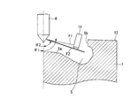
- FIG. 2 shows a more specific cross-sectional shape of the cavity combustion chamber 5.
- This cavity combustion chamber 5 is a reentrant type, and has a mountain-shaped central protrusion 5a at the center of the bottom surface, and the diameter of the lip portion 5b at the inlet portion is relatively smaller than the maximum diameter at the height position near the middle. It has become a thing.
- the piston top surface 13 remaining annularly around the cavity combustion chamber 5 is along a plane orthogonal to the piston center axis, and is substantially the same plane as the top surface of the cylinder block 3 at the piston top dead center position. It becomes. Accordingly, at the piston top dead center position, a gap substantially equivalent to the thickness of the cylinder head gasket 12 (see FIG.
- the fuel injection nozzle 6 includes two injection hole groups having different inclination angles with respect to the cylinder center axis.
- the straight line indicated by reference numeral F1 indicates the spray center axis of the first nozzle hole group.
- the first nozzle hole group includes a plurality of nozzle holes, for example, four to six nozzle holes, arranged at regular intervals in the circumferential direction. These nozzle holes (hereinafter referred to as the first nozzle holes as necessary). Each of which has the same inclination angle ⁇ 1 with respect to the cylinder center axis. Accordingly, the plurality of sprays are formed along a cone having an inclination angle ⁇ 1 centered on the cylinder center axis.
- the spray center axis F1 of each nozzle hole belonging to the first nozzle hole group is directed near the cylindrical surface of the lip portion 5b at the piston top dead center position.
- the straight line indicated by the symbol F2 indicates the spray center axis of the second nozzle hole group.
- the second nozzle hole group includes a plurality of nozzle holes, for example, four to six nozzle holes, arranged at equal intervals in the circumferential direction.
- the second injection holes are also referred to as the second injection holes as required) and have the same inclination angle ⁇ 2 with respect to the cylinder center axis. Accordingly, the plurality of sprays are formed along a cone having an inclination angle ⁇ 2 centered on the cylinder center axis.
- the inclination angle ⁇ 2 of the second nozzle hole group is smaller than the inclination angle ⁇ 1 of the first nozzle hole group, and the spray center axis F2 of each nozzle hole belonging to the second nozzle hole group is the piston top dead center. In the position, it is directed to a position below the lower end of the lip portion 5b, that is, the inside of the cavity combustion chamber 5 whose diameter is larger than that of the lip portion 5b.
- the nozzle holes of the first nozzle hole group are arranged radially at equal intervals, and similarly, the nozzle holes of the second nozzle hole group are radially arranged at equal intervals.
- the relationship between the two in a plan view is such that one second nozzle hole is positioned between two adjacent first nozzle holes, that is, the first nozzle hole and the second nozzle hole.
- the nozzle holes are alternately arranged in the circumferential direction.
- the nozzle hole diameter of the second nozzle hole belonging to the second nozzle hole group is larger than the nozzle hole diameter of the first nozzle hole belonging to the first nozzle hole group.
- the penetration force of each spray by the second nozzle hole group becomes the penetration force of each spray by the first nozzle hole group. Will be bigger.
- the amount of fuel ejected from each nozzle hole is larger in the second nozzle hole than in the first nozzle hole.
- FIG. 3 is an explanatory view showing a state of spray formed in the combustion chamber by the first nozzle hole group and the second nozzle hole group in a plan view when the cylinder 4 is viewed from above.
- Reference numerals 51 and 53 indicate the shapes of the initial sprays formed along the spray center axis F1 by the first nozzle holes directed relatively upward. These sprays 51 and 53 spread as time passes, as indicated by reference numerals 61 and 63, and flow downstream by the swirl S.
- Reference numeral 52 indicates the shape of the initial spray formed along the spray center axis F2 by the second nozzle hole directed relatively downward. The spray 52 similarly spreads as time passes as indicated by reference numeral 62 and flows to the downstream side of the swirl S.
- the glow plug 11 is located near the outer periphery of the inlet portion of the cavity combustion chamber 5 in the radial direction as shown in FIG. Is positioned between the spray center axis F1 of the first nozzle hole and the spray center axis F2 of the second nozzle so that the initial sprays 51, 52, 53 do not hit directly.
- the second nozzle hole having a relatively large nozzle hole diameter is disposed at a position downstream of the swirl center axis F2 of the spray center axis F2.
- the glow plug 11 protrudes to the height of the spray center axis F2 of the second nozzle hole group that is relatively directed to the lower position in the height direction of the cylinder 4.
- the fuel spray injected at a predetermined injection timing before the compression top dead center reaches the piston 1 when the piston 1 is near the top dead center.
- the fuel spray injected along the spray center axes F1 and F2 from each nozzle hole is affected by the swirl S existing in the cylinder, and as shown in FIG. It spreads.
- the glow plug 11 that is energized at the time of cold start is located on the swirl downstream side of the spray center axis F2 of the second nozzle hole, the fuel mass 62 in which the spray 52 from the second nozzle hole diffuses downstream of the swirl. First contacts the glow plug 11. Then, as a result of the further swirling of the spray to the downstream side of the swirl, the fuel mass due to the spray 53 from the first nozzle hole indicated by the reference numeral 63 comes into contact with the glow plug 11 next.
- the glow plug 11 protrudes to the height of the spray center axis F2 of the second nozzle hole, the fuel masses of both the spray of the first nozzle hole and the spray of the second nozzle hole are reliably transferred to the glow plug 11. Contact. Therefore, the ignitability during cold by the glow plug 11 is improved.
- the glow plug 11 is located downstream of the swirl of the spray 52 by the second nozzle hole having a large nozzle hole diameter and a relatively large fuel injection amount. A large amount of fuel lump comes into contact first, and more reliable ignition is obtained.
- the glow plug 11 is not prematurely deteriorated.
- the cavity combustion chamber 5 as a whole is dispersed.
- the air can be used more effectively.
- the diameter of the second nozzle hole group toward the inside of the cavity combustion chamber 5 is set to be larger, the fuel in an appropriate ratio corresponding to the shape of the cavity combustion chamber 5 is supplied from each nozzle hole group.
- FIGS. 4 and 5 show a second embodiment of the present invention.
- This embodiment includes a first nozzle hole group with a large inclination angle with respect to the cylinder center axis and a second nozzle hole group with a small inclination angle with respect to the cylinder center axis, as in the above-described embodiment.
- the nozzle hole diameter of the first nozzle hole relatively directed upward is larger than the nozzle diameter of the second nozzle hole relatively directed downward. ing. Therefore, the amount of fuel injected from the first nozzle hole is relatively larger than the amount of fuel injected from the second nozzle hole.
- the glow plug 11 is disposed on the swirl downstream side of the spray center axis F1 of the first nozzle hole having a large nozzle hole diameter.
- the height direction of the cylinder is the same as in the above-described embodiment, and the glow plug 11 protrudes to the height of the spray center axis F2 of the second nozzle hole that is directed relatively downward. Therefore, similarly to the above-described embodiment, high ignitability can be obtained while suppressing the deterioration of the glow plug 11.
- the present invention is not limited to the above-described embodiment, and various modifications can be made.
- the nozzle hole diameter of the first nozzle hole group and the nozzle hole diameter of the second nozzle hole group are different from each other.
- the glow plug 11 may be located on either the swirl downstream side of the spray center axis F1 of the first nozzle hole or the swirl downstream side of the spray center axis F2 of the second nozzle hole group.
Abstract
Description
ピストン上死点位置で先端部が上記キャビティ燃焼室内に入るように天井面から突出したグロープラグを備え、
上記燃料噴射ノズルは、シリンダ中心軸線に対する傾斜角が互いに異なる第1の噴孔群と第2の噴孔群とを有し、
第1の噴孔群に属する複数の第1の噴孔は、各々の噴霧中心軸線が放射状となるように配置され、かつ第2の噴孔群に属する複数の第2の噴孔は、各々の噴霧中心軸線が放射状となるように配置され、さらに、第1の噴孔と第2の噴孔とが周方向に交互に配置されており、
上記グロープラグは、周方向において、第1の噴孔の噴霧中心軸線と第2の噴孔の噴霧中心軸線との間に位置し、かつ、シリンダの高さ方向において、相対的に下側の位置を指向する一方の噴霧中心軸線の高さまで突出している。 This invention has a cavity combustion chamber at the center of the piston top surface, a fuel injection nozzle having a multi-injection hole is disposed at a substantially central position of the cavity combustion chamber, and a direct injection type in which a swirl is generated in the cylinder. In diesel engines,
A glow plug that protrudes from the ceiling surface so that the tip part enters the cavity combustion chamber at the piston top dead center position,
The fuel injection nozzle has a first nozzle hole group and a second nozzle hole group having different inclination angles with respect to the cylinder central axis,
The plurality of first nozzle holes belonging to the first nozzle hole group are arranged such that each spray center axis is radial, and the plurality of second nozzle holes belonging to the second nozzle hole group are respectively Are arranged such that the spray center axis is radial, and the first nozzle holes and the second nozzle holes are alternately arranged in the circumferential direction,
The glow plug is positioned between the spray center axis of the first nozzle hole and the spray center axis of the second nozzle hole in the circumferential direction, and is relatively lower in the height direction of the cylinder. It protrudes to the height of one spray center axis that is directed to the position.
上記のような構成においては、圧縮上死点前の所定の噴射時期に噴射された燃料噴霧は、ピストン1が上死点付近にあるときにピストン1に到達する。ここで、各噴孔から噴霧中心軸線F1,F2に沿って噴射された燃料噴霧は、筒内に存在するスワールSの影響を受け、図3に示したように、該スワールSの下流側へ拡散していく。冷間始動時に通電されるグロープラグ11は、第2の噴孔の噴霧中心軸線F2のスワール下流側に位置するので、第2の噴孔からの噴霧52がスワール下流側に拡散した燃料塊62が最初にグロープラグ11に接触する。そして、その後、噴霧がさらにスワール下流側に旋回していく結果、符号63でもって示す第1の噴孔からの噴霧53による燃料塊が次にグロープラグ11に接触する。 Further, as shown in FIG. 2, the
In the configuration as described above, the fuel spray injected at a predetermined injection timing before the compression top dead center reaches the
Claims (6)
- ピストン頂面中央部にキャビティ燃焼室を有するとともに、このキャビティ燃焼室の略中心位置に多噴孔の燃料噴射ノズルが配置され、かつシリンダ内にスワールを生成するようにした直噴式ディーゼルエンジンにおいて、
ピストン上死点位置で先端部が上記キャビティ燃焼室内に入るように天井面から突出したグロープラグを備え、
上記燃料噴射ノズルは、シリンダ中心軸線に対する傾斜角が互いに異なる第1の噴孔群と第2の噴孔群とを有し、
第1の噴孔群に属する複数の第1の噴孔は、各々の噴霧中心軸線が放射状となるように配置され、かつ第2の噴孔群に属する複数の第2の噴孔は、各々の噴霧中心軸線が放射状となるように配置され、さらに、第1の噴孔と第2の噴孔とが周方向に交互に配置されており、
上記グロープラグは、周方向において、第1の噴孔の噴霧中心軸線と第2の噴孔の噴霧中心軸線との間に位置し、かつ、シリンダの高さ方向において、相対的に下側の位置を指向する一方の噴霧中心軸線の高さまで突出している、直噴式ディーゼルエンジン。 In the direct injection diesel engine having a cavity combustion chamber at the center of the piston top surface, a fuel injection nozzle with multiple injection holes arranged at a substantially central position of the cavity combustion chamber, and generating a swirl in the cylinder,
A glow plug that protrudes from the ceiling surface so that the tip part enters the cavity combustion chamber at the piston top dead center position,
The fuel injection nozzle has a first nozzle hole group and a second nozzle hole group having different inclination angles with respect to the cylinder central axis,
The plurality of first nozzle holes belonging to the first nozzle hole group are arranged such that each spray center axis is radial, and the plurality of second nozzle holes belonging to the second nozzle hole group are respectively Are arranged such that the spray center axis is radial, and the first nozzle holes and the second nozzle holes are alternately arranged in the circumferential direction,
The glow plug is positioned between the spray center axis of the first nozzle hole and the spray center axis of the second nozzle hole in the circumferential direction, and is relatively lower in the height direction of the cylinder. A direct-injection diesel engine that protrudes to the height of one spray center axis that points to the position. - 一方の噴孔群の噴孔径は、他方の噴孔群の噴孔径よりも大きく、
上記グロープラグは、周方向において、噴孔径が相対的に大きい噴孔の噴霧中心軸線のスワール下流側に位置する、請求項1に記載の直噴式ディーゼルエンジン。 The nozzle hole diameter of one nozzle hole group is larger than the nozzle hole diameter of the other nozzle hole group,
The direct-injection diesel engine according to claim 1, wherein the glow plug is located on the swirl downstream side of the spray center axis of the nozzle hole having a relatively large nozzle hole diameter in the circumferential direction. - 相対的に上側の位置を指向する噴孔群の噴孔径に比べて、相対的に下側の位置を指向する噴孔群の噴孔径が大きい、請求項2に記載の直噴式ディーゼルエンジン。 3. The direct injection diesel engine according to claim 2, wherein the diameter of the nozzle hole group relatively directed to the lower position is larger than the diameter of the nozzle hole group directed to the relatively upper position.
- 上記燃料噴射ノズルは、シリンダの中心軸線に沿うように垂直に配置されている、請求項1~3のいずれかに記載の直噴式ディーゼルエンジン。 The direct-injection diesel engine according to any one of claims 1 to 3, wherein the fuel injection nozzle is arranged vertically along the central axis of the cylinder.
- 上記キャビティ燃焼室は、中間付近の最大径に比べて入口部分の径が相対的に小さなリエントラント型燃焼室である、請求項1~4のいずれかに記載の直噴式ディーゼルエンジン。 The direct injection diesel engine according to any one of claims 1 to 4, wherein the cavity combustion chamber is a reentrant combustion chamber in which a diameter of an inlet portion is relatively smaller than a maximum diameter in the vicinity of the middle.
- 上記キャビティ燃焼室は、ピストン中心軸線を中心とした回転体形状をなしている、請求項1~5のいずれかに記載の直噴式ディーゼルエンジン。 The direct injection diesel engine according to any one of claims 1 to 5, wherein the cavity combustion chamber has a rotating body shape centered on a piston center axis.
Priority Applications (4)
| Application Number | Priority Date | Filing Date | Title |
|---|---|---|---|
| EP14800826.1A EP3001009B1 (en) | 2013-05-20 | 2014-01-21 | Direct injection diesel engine |
| JP2014538028A JP5641169B1 (en) | 2013-05-20 | 2014-01-21 | Direct injection diesel engine |
| US14/889,520 US9879590B2 (en) | 2013-05-20 | 2014-01-21 | Direct injection diesel engine |
| CN201480029333.5A CN105264196B (en) | 2013-05-20 | 2014-01-21 | DI diesel engine |
Applications Claiming Priority (2)
| Application Number | Priority Date | Filing Date | Title |
|---|---|---|---|
| JP2013-105737 | 2013-05-20 | ||
| JP2013105737 | 2013-05-20 |
Publications (1)
| Publication Number | Publication Date |
|---|---|
| WO2014188736A1 true WO2014188736A1 (en) | 2014-11-27 |
Family
ID=51933303
Family Applications (1)
| Application Number | Title | Priority Date | Filing Date |
|---|---|---|---|
| PCT/JP2014/051095 WO2014188736A1 (en) | 2013-05-20 | 2014-01-21 | Direct injection diesel engine |
Country Status (5)
| Country | Link |
|---|---|
| US (1) | US9879590B2 (en) |
| EP (1) | EP3001009B1 (en) |
| JP (1) | JP5641169B1 (en) |
| CN (1) | CN105264196B (en) |
| WO (1) | WO2014188736A1 (en) |
Cited By (2)
| Publication number | Priority date | Publication date | Assignee | Title |
|---|---|---|---|---|
| JP2016160894A (en) * | 2015-03-04 | 2016-09-05 | トヨタ自動車株式会社 | Internal combustion engine |
| JP2020106004A (en) * | 2018-12-28 | 2020-07-09 | 株式会社クボタ | engine |
Families Citing this family (6)
| Publication number | Priority date | Publication date | Assignee | Title |
|---|---|---|---|---|
| DE102019114448A1 (en) * | 2019-05-29 | 2020-12-03 | Volkswagen Aktiengesellschaft | Injector with injection openings lying in one plane with different injection jet positions for fuel injection in two planes of a combustion chamber |
| CN112780465A (en) * | 2021-03-04 | 2021-05-11 | 哈尔滨工程大学 | Dual-fuel engine adopting gas high-pressure direct injection and stepped spray hole oil injector and combustion organization method thereof |
| US11644000B2 (en) | 2021-08-25 | 2023-05-09 | Caterpillar Inc. | Fuel injector clamp assembly for offset clamping bolt and cylinder head assembly with same |
| US11608804B1 (en) | 2021-08-25 | 2023-03-21 | Caterpillar Inc. | Fuel injector having side-fitted fuel connector for tight packaging in top-feed fuel system |
| US11603817B1 (en) | 2021-08-25 | 2023-03-14 | Caterpillar Inc. | Slim-profile fuel injector for tight packaging in top feed fuel system |
| US11898516B2 (en) | 2021-08-25 | 2024-02-13 | Caterpillar Inc. | Cylinder head having bore locations arranged for tight packaging of gas exchange and fuel system components |
Citations (7)
| Publication number | Priority date | Publication date | Assignee | Title |
|---|---|---|---|---|
| JPS54106419U (en) * | 1978-01-13 | 1979-07-26 | ||
| JPH0674131A (en) | 1992-06-05 | 1994-03-15 | Agency Of Ind Science & Technol | Two-stage injection methanol engine |
| JPH0921321A (en) * | 1995-07-05 | 1997-01-21 | Toyota Autom Loom Works Ltd | Fuel injection method for direct injection type diesel engine, piston and injection nozzle employed by the method |
| JP2000002116A (en) * | 1998-06-16 | 2000-01-07 | Nissan Motor Co Ltd | Direct injection type diesel engine |
| JP2002364366A (en) * | 2001-06-11 | 2002-12-18 | Toyota Motor Corp | Combustion chamber for diesel engine and structure of injection nozzle |
| JP2005120832A (en) | 2003-10-14 | 2005-05-12 | Yoshinobu Shimoitani | Fuel injection nozzle |
| JP2010071094A (en) * | 2008-09-16 | 2010-04-02 | Isuzu Motors Ltd | Direct-injection diesel engine |
Family Cites Families (3)
| Publication number | Priority date | Publication date | Assignee | Title |
|---|---|---|---|---|
| US4635597A (en) * | 1985-01-16 | 1987-01-13 | Yanmar Diesel Engine Co., Ltd. | Structure of a main combustion chamber of a diesel engine of a direct injection type |
| JP2003214297A (en) | 2002-01-24 | 2003-07-30 | Yanmar Co Ltd | Fuel injection valve of diesel engine |
| DE102010063355A1 (en) | 2010-12-17 | 2012-06-21 | Robert Bosch Gmbh | Fuel injection valve for internal combustion engines |
-
2014
- 2014-01-21 EP EP14800826.1A patent/EP3001009B1/en not_active Not-in-force
- 2014-01-21 JP JP2014538028A patent/JP5641169B1/en not_active Expired - Fee Related
- 2014-01-21 US US14/889,520 patent/US9879590B2/en not_active Expired - Fee Related
- 2014-01-21 CN CN201480029333.5A patent/CN105264196B/en not_active Expired - Fee Related
- 2014-01-21 WO PCT/JP2014/051095 patent/WO2014188736A1/en active Application Filing
Patent Citations (7)
| Publication number | Priority date | Publication date | Assignee | Title |
|---|---|---|---|---|
| JPS54106419U (en) * | 1978-01-13 | 1979-07-26 | ||
| JPH0674131A (en) | 1992-06-05 | 1994-03-15 | Agency Of Ind Science & Technol | Two-stage injection methanol engine |
| JPH0921321A (en) * | 1995-07-05 | 1997-01-21 | Toyota Autom Loom Works Ltd | Fuel injection method for direct injection type diesel engine, piston and injection nozzle employed by the method |
| JP2000002116A (en) * | 1998-06-16 | 2000-01-07 | Nissan Motor Co Ltd | Direct injection type diesel engine |
| JP2002364366A (en) * | 2001-06-11 | 2002-12-18 | Toyota Motor Corp | Combustion chamber for diesel engine and structure of injection nozzle |
| JP2005120832A (en) | 2003-10-14 | 2005-05-12 | Yoshinobu Shimoitani | Fuel injection nozzle |
| JP2010071094A (en) * | 2008-09-16 | 2010-04-02 | Isuzu Motors Ltd | Direct-injection diesel engine |
Cited By (2)
| Publication number | Priority date | Publication date | Assignee | Title |
|---|---|---|---|---|
| JP2016160894A (en) * | 2015-03-04 | 2016-09-05 | トヨタ自動車株式会社 | Internal combustion engine |
| JP2020106004A (en) * | 2018-12-28 | 2020-07-09 | 株式会社クボタ | engine |
Also Published As
| Publication number | Publication date |
|---|---|
| US20160084148A1 (en) | 2016-03-24 |
| EP3001009A4 (en) | 2016-06-01 |
| CN105264196A (en) | 2016-01-20 |
| JP5641169B1 (en) | 2014-12-17 |
| CN105264196B (en) | 2018-06-19 |
| US9879590B2 (en) | 2018-01-30 |
| JPWO2014188736A1 (en) | 2017-02-23 |
| EP3001009B1 (en) | 2018-02-28 |
| EP3001009A1 (en) | 2016-03-30 |
Similar Documents
| Publication | Publication Date | Title |
|---|---|---|
| JP5641169B1 (en) | Direct injection diesel engine | |
| JP4280928B2 (en) | Direct injection spark ignition internal combustion engine | |
| WO2015177898A1 (en) | Combustion chamber structure for diesel engine | |
| US8347853B2 (en) | Shallow piston bowl and injector spray pattern for a gasoline, direct-injection engine | |
| CN108026880B (en) | Engine | |
| US9970350B2 (en) | Opposed piston engine with pistons having conical recesses therein | |
| JP6303290B2 (en) | Direct injection diesel engine | |
| JP7047751B2 (en) | Compression ignition engine | |
| JP6508240B2 (en) | Spark-ignition type internal combustion engine | |
| US20130263813A1 (en) | Cylinder head for an internal combustion engine | |
| US10968817B2 (en) | Spark-ignition internal combustion engine | |
| US10907533B2 (en) | Spark-ignition internal combustion engine | |
| CN108026881B (en) | Engine | |
| US8418673B2 (en) | Fuel injection method for diesel engine and diesel engine | |
| JP2014156852A (en) | Compression ignition engine | |
| JP2004162577A (en) | Cylinder injection type spark ignition internal combustion engine | |
| KR20200069920A (en) | Piston combustion chamber structure of engine | |
| JP5120002B2 (en) | In-cylinder direct injection spark ignition internal combustion engine | |
| US20220220921A1 (en) | Passive prechamber lean burn combustion system | |
| US10968816B2 (en) | Spark-ignition internal combustion engine | |
| JP6515943B2 (en) | Spark-ignition type internal combustion engine | |
| WO2015087137A2 (en) | Compression ignition internal combustion engine | |
| JP2012002201A (en) | Internal combustion engine |
Legal Events
| Date | Code | Title | Description |
|---|---|---|---|
| WWE | Wipo information: entry into national phase |
Ref document number: 201480029333.5 Country of ref document: CN |
|
| ENP | Entry into the national phase |
Ref document number: 2014538028 Country of ref document: JP Kind code of ref document: A |
|
| 121 | Ep: the epo has been informed by wipo that ep was designated in this application |
Ref document number: 14800826 Country of ref document: EP Kind code of ref document: A1 |
|
| WWE | Wipo information: entry into national phase |
Ref document number: 2014800826 Country of ref document: EP |
|
| WWE | Wipo information: entry into national phase |
Ref document number: 14889520 Country of ref document: US |
|
| NENP | Non-entry into the national phase |
Ref country code: DE |