WO2014175053A1 - 乾留装置 - Google Patents
乾留装置 Download PDFInfo
- Publication number
- WO2014175053A1 WO2014175053A1 PCT/JP2014/060132 JP2014060132W WO2014175053A1 WO 2014175053 A1 WO2014175053 A1 WO 2014175053A1 JP 2014060132 W JP2014060132 W JP 2014060132W WO 2014175053 A1 WO2014175053 A1 WO 2014175053A1
- Authority
- WO
- WIPO (PCT)
- Prior art keywords
- gas
- dry distillation
- carbonization
- low
- reference gas
- Prior art date
- Legal status (The legal status is an assumption and is not a legal conclusion. Google has not performed a legal analysis and makes no representation as to the accuracy of the status listed.)
- Ceased
Links
Images


Classifications
-
- C—CHEMISTRY; METALLURGY
- C10—PETROLEUM, GAS OR COKE INDUSTRIES; TECHNICAL GASES CONTAINING CARBON MONOXIDE; FUELS; LUBRICANTS; PEAT
- C10B—DESTRUCTIVE DISTILLATION OF CARBONACEOUS MATERIALS FOR PRODUCTION OF GAS, COKE, TAR, OR SIMILAR MATERIALS
- C10B21/00—Heating of coke ovens with combustible gases
- C10B21/10—Regulating and controlling the combustion
-
- C—CHEMISTRY; METALLURGY
- C10—PETROLEUM, GAS OR COKE INDUSTRIES; TECHNICAL GASES CONTAINING CARBON MONOXIDE; FUELS; LUBRICANTS; PEAT
- C10B—DESTRUCTIVE DISTILLATION OF CARBONACEOUS MATERIALS FOR PRODUCTION OF GAS, COKE, TAR, OR SIMILAR MATERIALS
- C10B47/00—Destructive distillation of solid carbonaceous materials with indirect heating, e.g. by external combustion
- C10B47/28—Other processes
- C10B47/30—Other processes in rotary ovens or retorts
-
- C—CHEMISTRY; METALLURGY
- C10—PETROLEUM, GAS OR COKE INDUSTRIES; TECHNICAL GASES CONTAINING CARBON MONOXIDE; FUELS; LUBRICANTS; PEAT
- C10B—DESTRUCTIVE DISTILLATION OF CARBONACEOUS MATERIALS FOR PRODUCTION OF GAS, COKE, TAR, OR SIMILAR MATERIALS
- C10B41/00—Safety devices, e.g. signalling or controlling devices for use in the discharge of coke
-
- C—CHEMISTRY; METALLURGY
- C10—PETROLEUM, GAS OR COKE INDUSTRIES; TECHNICAL GASES CONTAINING CARBON MONOXIDE; FUELS; LUBRICANTS; PEAT
- C10B—DESTRUCTIVE DISTILLATION OF CARBONACEOUS MATERIALS FOR PRODUCTION OF GAS, COKE, TAR, OR SIMILAR MATERIALS
- C10B41/00—Safety devices, e.g. signalling or controlling devices for use in the discharge of coke
- C10B41/08—Safety devices, e.g. signalling or controlling devices for use in the discharge of coke for the withdrawal of the distillation gases
-
- C—CHEMISTRY; METALLURGY
- C10—PETROLEUM, GAS OR COKE INDUSTRIES; TECHNICAL GASES CONTAINING CARBON MONOXIDE; FUELS; LUBRICANTS; PEAT
- C10B—DESTRUCTIVE DISTILLATION OF CARBONACEOUS MATERIALS FOR PRODUCTION OF GAS, COKE, TAR, OR SIMILAR MATERIALS
- C10B53/00—Destructive distillation, specially adapted for particular solid raw materials or solid raw materials in special form
- C10B53/02—Destructive distillation, specially adapted for particular solid raw materials or solid raw materials in special form of cellulose-containing material
-
- F—MECHANICAL ENGINEERING; LIGHTING; HEATING; WEAPONS; BLASTING
- F27—FURNACES; KILNS; OVENS; RETORTS
- F27B—FURNACES, KILNS, OVENS OR RETORTS IN GENERAL; OPEN SINTERING OR LIKE APPARATUS
- F27B7/00—Rotary-drum furnaces, i.e. horizontal or slightly inclined
- F27B7/20—Details, accessories or equipment specially adapted for rotary-drum furnaces
- F27B7/32—Arrangement of devices for charging
-
- F—MECHANICAL ENGINEERING; LIGHTING; HEATING; WEAPONS; BLASTING
- F27—FURNACES; KILNS; OVENS; RETORTS
- F27B—FURNACES, KILNS, OVENS OR RETORTS IN GENERAL; OPEN SINTERING OR LIKE APPARATUS
- F27B7/00—Rotary-drum furnaces, i.e. horizontal or slightly inclined
- F27B7/20—Details, accessories or equipment specially adapted for rotary-drum furnaces
- F27B7/33—Arrangement of devices for discharging
-
- F—MECHANICAL ENGINEERING; LIGHTING; HEATING; WEAPONS; BLASTING
- F27—FURNACES; KILNS; OVENS; RETORTS
- F27B—FURNACES, KILNS, OVENS OR RETORTS IN GENERAL; OPEN SINTERING OR LIKE APPARATUS
- F27B7/00—Rotary-drum furnaces, i.e. horizontal or slightly inclined
- F27B7/20—Details, accessories or equipment specially adapted for rotary-drum furnaces
- F27B7/42—Arrangement of controlling, monitoring, alarm or like devices
-
- Y—GENERAL TAGGING OF NEW TECHNOLOGICAL DEVELOPMENTS; GENERAL TAGGING OF CROSS-SECTIONAL TECHNOLOGIES SPANNING OVER SEVERAL SECTIONS OF THE IPC; TECHNICAL SUBJECTS COVERED BY FORMER USPC CROSS-REFERENCE ART COLLECTIONS [XRACs] AND DIGESTS
- Y02—TECHNOLOGIES OR APPLICATIONS FOR MITIGATION OR ADAPTATION AGAINST CLIMATE CHANGE
- Y02E—REDUCTION OF GREENHOUSE GAS [GHG] EMISSIONS, RELATED TO ENERGY GENERATION, TRANSMISSION OR DISTRIBUTION
- Y02E50/00—Technologies for the production of fuel of non-fossil origin
- Y02E50/10—Biofuels, e.g. bio-diesel
Definitions
- the present invention relates to a carbonization apparatus that continuously heats and circulates solid organic matter and continuously performs carbonization.
- a rotary kiln described in Patent Document 1 In the case of continuous distillation by heating while circulating solid organic matter, for example, a rotary kiln described in Patent Document 1 below can be applied.
- the rotary kiln described in Patent Document 1 supplies organic matter (processed product) to the inner cylinder (furnace core tube) and rotates the inner cylinder, thereby circulating the organic matter inside the inner cylinder.
- the hot air can be blown into the outer cylinder (heating furnace) to heat the organic matter and continuously dry, and the temperature of the hot air can be measured by measuring the temperature of the organic matter with a thermocouple provided in the inner cylinder. Can be adjusted.
- the temperature of the organic matter in contact with the thermocouple is determined as the temperature of the entire organic matter, and therefore the temperature of the organic matter in contact with the thermocouple is the organic matter. If the temperature is greatly deviated from the overall average temperature, the whole organic matter is not heated with a necessary and sufficient amount of heat, and there is a possibility that the whole organic matter cannot be dry-distilled at the intended dry distillation rate (degree).
- an object of the present invention is to provide a carbonization apparatus that can accurately perform carbonization at the rate of carbonization for the whole organic matter.
- a carbonization apparatus is a furnace main body for circulating a solid organic substance therein, an organic substance supply means for supplying the organic substance into the furnace main body,
- the heating means for heating the organic matter inside the furnace body, the sending means for sending the solid dry matter and the dry distillation gas heated and dry distilled inside the furnace body, and the dry distillation gas comprises an inert gas Reference gas supply means for adding a reference gas, and carbon monoxide, carbon dioxide, hydrogen gas, hydrocarbon gas, H 2 O in a mixed gas of the dry distillation gas and the reference gas sent from the sending means
- Gas concentration measuring means for measuring the calibration gas concentration Cc and the reference gas concentration Cs, and the calibration gas concentration Cc and the reference gas concentration measured by the gas concentration measurement means.
- the flow rate Fs per unit time of the reference gas added from the reference gas supply means, and the weight Wo per unit time of the organic matter supplied from the organic matter supply means to the inside of the furnace body is calculated from the following formula (1), and the calibration gas generation ratio Fc and the organic substance per unit weight of the organic substance input in advance are calculated.
- the calculation control means increases the heating temperature of the organic matter when the dry distillation rate Dt is smaller than the dry distillation rate Dr. And controlling the heating means.
- the dry distillation apparatus according to the third invention is the heating temperature of the organic matter when the calculation control means in the first or second invention is such that the dry distillation rate Dt is larger than the dry distillation rate Dr.
- the heating means is controlled so as to lower the temperature.
- the heating means heats the furnace body from the outside.
- the reference gas supply means supplies the reference gas to the upstream side of the furnace body in the circulation direction of the organic matter. It is what supplies.
- the carbonization apparatus according to the sixth invention is characterized in that, in any of the first to fifth inventions, the organic matter is low-grade coal.
- the calculation control means includes the calibration gas based on the calibration gas concentration Cc, the reference gas concentration Cs, the reference gas flow rate Fs, and the organic substance weight Wo. Is calculated from the equation (1), and a dry distillation rate Dt of the organic matter is obtained from a relation map between the generation amount Fc of the calibration gas and the dry distillation rate of the organic matter, which is input in advance. Since the heating means is controlled so that the ratio Dt is the target dry distillation ratio Dr, the heating amount of the organic substance can be set based on the total dry distillation ratio (degree) of the organic substance after the end of the dry distillation.
- the entire organic matter in the furnace main body can be heated with a necessary and sufficient amount of heat without being affected by the variation.
- the whole organic matter can be subjected to dry distillation with high accuracy at the intended dry distillation rate Dr.
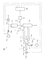
- FIG. 1 It is a schematic block diagram of main embodiment of the carbonization apparatus which concerns on this invention.
- the low of the carbon monoxide generation amount per unit weight from the low-grade coal and the dry distillation rate (degree) of the low-grade coal which is input in advance to the calculation control means of another embodiment of the carbonization apparatus according to the present invention. It is a relationship map for each grade of rank coal.
- an inner cylinder (furnace body) 112 is rotatably supported inside a fixedly supported outer cylinder (jacket) 111.
- a supply feeder 113 that feeds low-grade coal (low-quality coal) 1 such as dried lignite or sub-bituminous coal, which is a solid organic substance, to the base end side (left side in FIG. 1) of the inner cylinder 112
- the distal end side (the right side in FIG. 1) is connected while allowing the inner cylinder 112 to rotate.
- a supply hopper 114 into which the low-grade coal 1 is put is provided on the base end side (left side in FIG. 1) of the supply feeder 113.
- a reference gas supply source 115 which is a reference gas supply means for supplying a reference gas 4 made of nitrogen gas is connected to the base end side of the inner cylinder 112 via a flow rate adjusting valve 115a.
- the carbonized carbon 2 that is a solid carbonized product obtained by carbonizing the low-grade coal 1 is dropped and sent downward, and the low-grade coal 1 is subjected to carbonization.
- a shooter 116 which is a sending means for sending the carbonized gas 3 generated therewith from above is connected while allowing the inner cylinder 112 to rotate. The upper part of the shooter 116 is connected to a combustion furnace 117 for burning the dry distillation gas 3.
- a fuel supply source 118 for supplying combustion fuel 5 such as natural gas to the inside of the combustion furnace 117 is connected to the combustion furnace 117 via a flow rate adjusting valve 118 a and to the inside of the combustion furnace 117.
- An air blower 119 for supplying combustion air 6 is connected, and the combustion furnace 117 can generate and send combustion gas 7 by burning the dry distillation gas 3 together with the fuel 5 and the air 6. It can be done.
- the delivery port of the combustion gas 7 of the combustion furnace 117 is connected to the inside of the outer cylinder 111.
- the outer cylinder 111 is connected to an exhaust line 111 a for discharging the combustion gas 7 fed into the outer cylinder 111 to the outside of the system.
- a gas concentration measuring device 131 such as a gas chromatograph, which is a gas concentration measuring means for measuring, is connected.
- the gas concentration measuring device 131 is electrically connected to an input unit of a calculation control device 130 that is a calculation control means.
- the output unit of the arithmetic and control unit 130 is electrically connected to the drive motor 113a of the supply feeder 113, the flow rate adjustment valve 115a of the reference gas supply source 115, the flow rate adjustment valve 118a of the fuel supply source 118, and the air blower 119.
- the arithmetic and control unit 130 is connected to the drive motor 113a, the flow rate adjusting valves 115a and 118a, the air blower 119, etc. based on the information from the gas concentration measuring device 131 and the information inputted in advance. Can be controlled (details will be described later).
- the supply feeder 113, the supply hopper 114, and the like constitute organic substance supply means, and the outer cylinder 111, the combustion furnace 117, the fuel supply source 118, the air blower 119, and the like provide heating means. It is composed.
- the low-grade coal 1 After putting the low-grade coal 1 into the supply hopper 114, the low-grade coal 1 varieties, the intended dry distillation rate (degree) Dr of the low-grade coal 1, the low grade coal supplied into the inner cylinder 112
- the arithmetic control device 130 controls the operation of the drive motor 113a of the supply feeder 113 so that the low-grade coal 1 is supplied into the inner cylinder 112 with the input weight Wo per unit time, and is input.
- the flow control valve 118a and the air blower 119 of the fuel supply source 118 are controlled to operate so that the fuel 5 and the air 6 are supplied at a reference flow rate at the start of operation, and the reference is set in the combustion furnace 117.
- a combustion gas 7 having a temperature is generated and fed into the outer cylinder 111.
- the low-grade coal 1 supplied into the inner cylinder 112 is moved from the proximal end side (left side in FIG. 1) to the distal end side (right side in FIG. 1) as the inner cylinder 112 rotates. At the same time as it is circulated while being stirred toward the outer cylinder 111, and is indirectly heated through the inner cylinder 112 by the combustion gas 7 fed into the outer cylinder 111, thereby being dry-distilled into the dry-distilled coal 2, It is sent out to the shooter 116 and sent out of the system from below the shooter 116.
- the combustion gas 7 that has heated the inner cylinder 112 is discharged out of the system through the exhaust line 111a.
- the dry distillation gas 3 generated by heating and dry distillation of the low-grade coal 1 is supplied from the reference gas supply source 115 to the upstream side in the flow direction of the low-grade coal 1 in the inner cylinder 112. While being mixed in the inner cylinder 112 with the gas 4, it is sent out to the shooter 116, becomes a mixed gas with the reference gas 4, and is sent from above the shooter 116, and a part thereof is sent to the gas concentration measuring device 131. On the other hand, the remainder is fed into the combustion furnace 117 and combusted together with the fuel 5 and the air 6 to become combustion gas 7 and fed into the outer cylinder 111.
- the gas concentration measuring device 131 measures the composition ratio (concentration) of carbon dioxide, which is a calibration gas in the sampled mixed gas, and the reference gas 4, and transmits the information to the arithmetic and control device 130.
- the arithmetic and control unit 130 receives the weight Wo per unit time of the low-grade coal 1 supplied into the inner cylinder 112 and the unit gas per unit time of the reference gas 4 supplied into the inner cylinder 112. Based on the flow rate Fs and information from the gas concentration measuring device 131, that is, the composition ratio (concentration) Cc of carbon dioxide in the mixed gas and the composition ratio (concentration) Cs of the reference gas 4, the low quality.
- the amount (volume) Fc of carbon dioxide generated per unit weight of charcoal is calculated from the following equation (1).
- the arithmetic and control unit 130 inputs a carbon dioxide generation amount (volume) Fc per unit weight of the low-grade coal 1 and a dry distillation reduction amount per unit weight of the low-grade coal 1 (preliminarily input).
- Weight that is, the carbon dioxide generation amount Fc corresponding to the previously input low-grade coal 1 type from the relationship map (see FIG. 2) with the carbonization rate (degree) Dt of the carbonized coal 2.
- the carbonization ratio (degree) Dt of the carbonized coal 2 corresponding to is obtained.
- the said arithmetic and control unit 130 compares the said carbonization rate (degree) Dt of the said carbonization coal 2 with the said carbonization rate (degree) Dr made into the objective previously input, and the said carbonization rate (degree) Dt Is a value that falls within an allowable error range of the carbonization rate (degree) Dr, it is determined that the low-grade coal 1 is carbonized at the carbonization rate (degree) Dr for the purpose, and the fuel 5
- the flow rate adjusting valve 118a of the fuel supply source 118 is controlled to be fed at a current flow rate.
- the arithmetic and control unit 130 determines that the carbonization reduction (weight) per unit weight of the low-grade coal 1 is small, that is, the carbonization rate (degree) of the carbonization coal 2 is small, and the fuel 5 is made to be less than the current flow rate.
- the temperature of the combustion gas 7 is raised by controlling the operation of the flow rate adjusting valve 118a of the fuel supply source 118 so that a large amount of fuel is supplied.
- the arithmetic and control unit 130 determines that the carbonization reduction (weight) per unit weight of the low-grade coal 1 is large, that is, the carbonization rate (degree) of the carbonization coal 2 is large, and the fuel 5 is more than the current flow rate.
- the flow rate adjusting valve 118a of the fuel supply source 118 is controlled to be fed so that the temperature of the combustion gas 7 is lowered.
- the carbonized coal 2 is always carbonized so as to have a target carbonization ratio (degree) Dr.
- the concentration of carbon dioxide (calibration gas) in the carbonized gas 3 after the carbonization sent from the shooter 116 together with the carbonized carbonized carbon 2 is detected.
- the carbonization rate (degree) of the carbonized coal 2 is obtained from the relationship map obtained in advance, and the temperature of the combustion gas 7 is adjusted.
- the heating amount of the low-grade coal 1 can be set from the overall dry distillation rate (degree) of the dry distillation coal 2 after the end of dry distillation. Even if the temperature of the low-grade coal 1 in 112 is partially greatly varied, the entire low-grade coal 1 can be heated with a necessary and sufficient amount of heat without being affected by the variation.
- the carbonization apparatus 100 it is possible to perform carbonization with high accuracy at the carbonization ratio Dr aimed at the entire low-grade coal 1.
- the reference gas 4 is supplied to the dry distillation gas 3, and the amount of carbon dioxide generated is determined based on the ratio of carbon dioxide in the dry distillation gas 3 to the reference gas 4, for example, Based on the flow rate of the dry distillation gas 3 sent from the shooter 116, the amount of carbon dioxide generated can be calculated with higher accuracy than when the amount of carbon dioxide generated is determined. Accurate carbonization can be more reliably performed with the intended carbonization ratio Dr.
- the reference gas supply source 115 is connected to the proximal end side of the inner cylinder 112, that is, the upstream side in the flow direction of the low-grade coal 1, and the reference gas supply 115 is connected to the inner cylinder 112.
- the gas 4 is supplied, as another embodiment, for example, the reference gas supply source 115 is connected between the shooter 116 and the gas concentration measuring device 131 to connect the reference gas to the dry distillation gas 3. It is also possible to supply 4.
- the reference gas supply source 115 is connected to the proximal end side of the inner cylinder 112, that is, the upstream side in the flow direction of the low-grade coal 1, and the inside of the inner cylinder 112 is If the reference gas 4 is supplied, the dry distillation gas 3 and the reference gas 4 can be easily and reliably mixed, which is very preferable.
- the low-grade coal 1 in the inner cylinder 112 is heated and dry-distilled with the combustion gas 7, but as another embodiment, for example, the inner cylinder 112 is It is also possible to dry-distill the low-grade coal 1 in the inner cylinder 112 by heating with an electric heater or the like.
- the low-grade coal 1 in the inner cylinder 112 is heated and dry-distilled with the combustion gas 7 as in the above-described embodiment, it is generated along with the dry-distillation of the low-grade coal 1. Since the dry distillation gas 3 can be used as a raw material of the combustion gas 7 and can be effectively used, it is very preferable.
- the low-grade coal 1 is indirectly heated and dry-distilled through the inner cylinder 112 by feeding the combustion gas 7 into the outer cylinder 111.
- the reference gas 4 is heated by circulating the combustion gas 7 through a heat exchanger and the reference gas 4 through the heat exchanger. It is also possible to supply the reference gas 4 into the inner cylinder 112 and directly heat the low-grade coal 1 to dry distillation.
- the reference gas 4 when the reference gas 4 is heated and the heated reference gas 4 is supplied into the inner cylinder 112 so that the low-grade coal 1 is directly heated to dry distillation, the reference gas 4 Since the gas 4 must be used in a large amount and the cost is increased, it is not preferable.
- carbon dioxide in the dry distillation gas 3 is applied as a calibration gas.
- carbon monoxide in the dry distillation gas 3 is applied as a calibration gas.
- the amount (volume) Fc of carbon monoxide generated per unit weight of the low-grade coal 1 and the carbonization loss (weight) per unit weight of the low-grade coal 1 that is, From the relationship map with the carbonization rate (degree) Dt of the carbonized coal 2, the carbonization rate of the carbonized coal 2 corresponding to the carbon monoxide generation amount Fc corresponding to the previously input low-grade coal 1 type (Degree) Obtaining Dt, or applying methane (hydrocarbon gas) in the dry distillation gas 3 as a calibration gas, as shown in FIG.
- methane from the unit weight of the low-grade coal 1 From the relationship map between the amount of raw material (volume) Fc and the dry distillation reduction (weight) per unit weight of the low-grade coal 1, that is, the dry distillation ratio (degree) Dt of the dry-distilled coal 2, the low-grade input previously. It is also possible to obtain the dry distillation ratio (degree) Dt of the carbonized coal 2 corresponding to the generation amount Fc of the methane (hydrocarbon gas) corresponding to the type of the coal 1.
- an appropriate type of calibration gas may be appropriately selected from the target value of the dry distillation rate Dt.
- a plurality of calibration gases can be selected and used in combination.
- the carbonization apparatus according to the present invention when the carbonization apparatus according to the present invention is applied to carbonization of low-grade coal (low-quality coal) such as lignite and sub-bituminous coal, the carbonization can be accurately carbonized at a carbonization ratio intended for the entire low-grade coal. Therefore, it can be used extremely beneficially in the industry.
- low-grade coal low-quality coal
Landscapes
- Chemical & Material Sciences (AREA)
- Engineering & Computer Science (AREA)
- Oil, Petroleum & Natural Gas (AREA)
- Materials Engineering (AREA)
- Organic Chemistry (AREA)
- Mechanical Engineering (AREA)
- General Engineering & Computer Science (AREA)
- Combustion & Propulsion (AREA)
- Production Of Liquid Hydrocarbon Mixture For Refining Petroleum (AREA)
- Solid Fuels And Fuel-Associated Substances (AREA)
- Coke Industry (AREA)
Abstract
Description
本発明に係る乾留装置の主な実施形態を図1,2に基づいて説明する。
なお、前述した実施形態においては、前記内筒112の基端側、すなわち、前記低品位炭1の流通方向上流側に前記基準ガス供給源115を接続して当該内筒112の内部に前記基準ガス4を供給するようにしたが、他の実施形態として、例えば、前記シュータ116と前記ガス濃度計測装置131との間に前記基準ガス供給源115を接続して前記乾留ガス3に前記基準ガス4を供給するようにすることも可能である。
2 乾留炭
3 乾留ガス
4 基準ガス
5 燃料
6 空気
7 燃焼ガス
100 乾留装置
111 外筒
112 内筒
113 供給フィーダ
113a 駆動モータ
114 供給ホッパ
115 基準ガス供給源
115a 流量調整バルブ
116 シュータ
117 燃焼炉
118 燃料供給源
118a 流量調整バルブ
119 エアブロア
130 演算制御装置
131 ガス濃度計測装置
Claims (6)
- 固形状の有機物を内部に流通させる炉本体と、
前記炉本体の内部に前記有機物を供給する有機物供給手段と、
前記炉本体の内部の前記有機物を加熱する加熱手段と、
前記炉本体の内部で加熱されて乾留された固形状の乾留物及び乾留ガスを送出する送出手段と、
前記乾留ガスに不活性ガスからなる基準ガスを加える基準ガス供給手段と、
前記送出手段から送出された前記乾留ガスと前記基準ガスとの混合ガス中の、一酸化炭素、二酸化炭素、水素ガス、炭化水素ガス、H2Oのうちの少なくとも一つからなる検量ガスの濃度Cc及び上記基準ガスの濃度Csを計測するガス濃度計測手段と、
前記ガス濃度計測手段で計測された前記検量ガスの濃度Cc及び前記基準ガスの濃度Cs、並びに、前記基準ガス供給手段から加えている前記基準ガスの単位時間当たりの流量Fs及び前記有機物供給手段から前記炉本体の内部に供給している前記有機物の単位時間当たりの重量Woに基づいて、当該有機物の単位重量当たりからの前記検量ガスの発生量Fcを下記式(1)から算出し、予め入力されている、当該検量ガスの発生量Fcと当該有機物の単位重量当たりの乾留割合との関係マップから、当該有機物の単位重量当たりの乾留割合Dtを求め、当該乾留割合Dtが、目的とする乾留割合Drとなるように前記加熱手段を制御する演算制御手段と
を備えていることを特徴とする乾留装置。
Fc={Fs(Cc/Cs)}/Wo (1) - 請求項1に記載の乾留装置において、
前記演算制御手段が、
前記乾留割合Dtが前記乾留割合Drよりも小さい場合には前記有機物の加熱温度を上昇させるように前記加熱手段を制御するものである
ことを特徴とする乾留装置。 - 請求項1又は請求項2に記載の乾留装置において、
前記演算制御手段が、
前記乾留割合Dtが前記乾留割合Drよりも大きい場合には前記有機物の加熱温度を下降させるように前記加熱手段を制御するものである
ことを特徴とする乾留装置。 - 請求項1から請求項3のいずれか一項に記載の乾留装置において、
前記加熱手段が、前記炉本体を外側から加熱するものである
ことを特徴とする乾留装置。 - 請求項1から請求項4のいずれか一項に記載の乾留装置において、
前記基準ガス供給手段が、前記炉本体の前記有機物の流通方向上流側に前記基準ガスを供給するものである
ことを特徴とする乾留装置。 - 請求項1から請求項5のいずれか一項に記載の乾留装置において、
前記有機物が、低品位炭である
ことを特徴とする乾留装置。
Priority Applications (4)
| Application Number | Priority Date | Filing Date | Title |
|---|---|---|---|
| AU2014258613A AU2014258613B2 (en) | 2013-04-26 | 2014-04-08 | Carbonization device |
| CN201480021523.2A CN105121601B (zh) | 2013-04-26 | 2014-04-08 | 干馏装置 |
| US14/782,635 US20160060531A1 (en) | 2013-04-26 | 2014-04-08 | Carbonization device |
| DE112014002125.3T DE112014002125T5 (de) | 2013-04-26 | 2014-04-08 | Verkokungsvorrichtung |
Applications Claiming Priority (2)
| Application Number | Priority Date | Filing Date | Title |
|---|---|---|---|
| JP2013093222A JP2014214236A (ja) | 2013-04-26 | 2013-04-26 | 乾留装置 |
| JP2013-093222 | 2013-04-26 |
Publications (1)
| Publication Number | Publication Date |
|---|---|
| WO2014175053A1 true WO2014175053A1 (ja) | 2014-10-30 |
Family
ID=51791634
Family Applications (1)
| Application Number | Title | Priority Date | Filing Date |
|---|---|---|---|
| PCT/JP2014/060132 Ceased WO2014175053A1 (ja) | 2013-04-26 | 2014-04-08 | 乾留装置 |
Country Status (6)
| Country | Link |
|---|---|
| US (1) | US20160060531A1 (ja) |
| JP (1) | JP2014214236A (ja) |
| CN (1) | CN105121601B (ja) |
| AU (1) | AU2014258613B2 (ja) |
| DE (1) | DE112014002125T5 (ja) |
| WO (1) | WO2014175053A1 (ja) |
Cited By (1)
| Publication number | Priority date | Publication date | Assignee | Title |
|---|---|---|---|---|
| CN109652128A (zh) * | 2018-11-30 | 2019-04-19 | 浙江天禄环境科技有限公司 | 一种利用低阶煤中的挥发分制液化烃的方法和系统 |
Families Citing this family (3)
| Publication number | Priority date | Publication date | Assignee | Title |
|---|---|---|---|---|
| JP7802683B2 (ja) * | 2020-11-10 | 2026-01-20 | Ube三菱セメント株式会社 | バイオマス固体燃料製造装置 |
| CN117553511A (zh) * | 2023-11-29 | 2024-02-13 | 长虹美菱股份有限公司 | 食材新鲜度监测冰箱及方法 |
| SE2430082A1 (en) * | 2024-02-20 | 2025-08-21 | Boban Nikolic | Arrangement and method for biochar pyrolysis |
Citations (3)
| Publication number | Priority date | Publication date | Assignee | Title |
|---|---|---|---|---|
| JPH07242882A (ja) * | 1994-03-08 | 1995-09-19 | Shin Meiwa Ind Co Ltd | 炭化装置 |
| JPH11131073A (ja) * | 1997-10-31 | 1999-05-18 | Shin Meiwa Ind Co Ltd | 炭化装置の温度制御方法 |
| JP2000314593A (ja) * | 1999-04-30 | 2000-11-14 | Kawasaki Heavy Ind Ltd | 外熱式ロータリーキルン |
Family Cites Families (2)
| Publication number | Priority date | Publication date | Assignee | Title |
|---|---|---|---|---|
| JP5400505B2 (ja) * | 2009-07-06 | 2014-01-29 | バブコック日立株式会社 | コークス炉ガスの無触媒改質方法及び改質装置 |
| CN102174336B (zh) * | 2011-02-25 | 2013-09-11 | 华东理工大学 | 多喷嘴对置式水煤浆气化炉炉膛温度控制装置及控制方法 |
-
2013
- 2013-04-26 JP JP2013093222A patent/JP2014214236A/ja not_active Ceased
-
2014
- 2014-04-08 WO PCT/JP2014/060132 patent/WO2014175053A1/ja not_active Ceased
- 2014-04-08 US US14/782,635 patent/US20160060531A1/en not_active Abandoned
- 2014-04-08 DE DE112014002125.3T patent/DE112014002125T5/de not_active Withdrawn
- 2014-04-08 CN CN201480021523.2A patent/CN105121601B/zh not_active Expired - Fee Related
- 2014-04-08 AU AU2014258613A patent/AU2014258613B2/en not_active Ceased
Patent Citations (3)
| Publication number | Priority date | Publication date | Assignee | Title |
|---|---|---|---|---|
| JPH07242882A (ja) * | 1994-03-08 | 1995-09-19 | Shin Meiwa Ind Co Ltd | 炭化装置 |
| JPH11131073A (ja) * | 1997-10-31 | 1999-05-18 | Shin Meiwa Ind Co Ltd | 炭化装置の温度制御方法 |
| JP2000314593A (ja) * | 1999-04-30 | 2000-11-14 | Kawasaki Heavy Ind Ltd | 外熱式ロータリーキルン |
Cited By (1)
| Publication number | Priority date | Publication date | Assignee | Title |
|---|---|---|---|---|
| CN109652128A (zh) * | 2018-11-30 | 2019-04-19 | 浙江天禄环境科技有限公司 | 一种利用低阶煤中的挥发分制液化烃的方法和系统 |
Also Published As
| Publication number | Publication date |
|---|---|
| AU2014258613A1 (en) | 2015-11-05 |
| AU2014258613B2 (en) | 2016-04-14 |
| CN105121601B (zh) | 2017-03-08 |
| US20160060531A1 (en) | 2016-03-03 |
| CN105121601A (zh) | 2015-12-02 |
| JP2014214236A (ja) | 2014-11-17 |
| DE112014002125T5 (de) | 2016-02-04 |
Similar Documents
| Publication | Publication Date | Title |
|---|---|---|
| CN101336280B (zh) | 优化控制的炼焦炉和控制方法 | |
| JP6500305B2 (ja) | 炭化物の製造方法及び炭化物の製造装置 | |
| JP2014214236A (ja) | 乾留装置 | |
| JP2009525361A5 (ja) | ||
| WO2014175054A1 (ja) | 乾留装置 | |
| CN103293177B (zh) | 一种快速升温气化测试装置及应用 | |
| JP6044958B2 (ja) | 乾留装置 | |
| JP5804971B2 (ja) | 改質石炭製造設備 | |
| CN103090545A (zh) | 瓦斯燃烧器具的加热调控方法 | |
| CN103323145B (zh) | 一种回转窑窑内烟气温度检测方法及装置 | |
| CN108062135A (zh) | 一种适用于烟草热物性测量的恒温试验装置及方法 | |
| JPS6153390A (ja) | 低品位炭の高品質化装置の温度制御方法 | |
| JP6690877B2 (ja) | 木質系バイオマスの炭化処理装置 | |
| CN203365356U (zh) | 快速升温气化测试装置 | |
| KR20160149648A (ko) | 코크스 제조 방법 | |
| JP4720755B2 (ja) | 燃焼性測定の前処理方法、燃料の評価方法およびセメントの製造方法 | |
| GB2489959A (en) | Continuous process pyrolyser |
Legal Events
| Date | Code | Title | Description |
|---|---|---|---|
| WWE | Wipo information: entry into national phase |
Ref document number: 201480021523.2 Country of ref document: CN |
|
| 121 | Ep: the epo has been informed by wipo that ep was designated in this application |
Ref document number: 14787639 Country of ref document: EP Kind code of ref document: A1 |
|
| WWE | Wipo information: entry into national phase |
Ref document number: 14782635 Country of ref document: US |
|
| WWE | Wipo information: entry into national phase |
Ref document number: IDP00201506885 Country of ref document: ID |
|
| WWE | Wipo information: entry into national phase |
Ref document number: 112014002125 Country of ref document: DE Ref document number: 1120140021253 Country of ref document: DE |
|
| ENP | Entry into the national phase |
Ref document number: 2014258613 Country of ref document: AU Date of ref document: 20140408 Kind code of ref document: A |
|
| 122 | Ep: pct application non-entry in european phase |
Ref document number: 14787639 Country of ref document: EP Kind code of ref document: A1 |