WO2014175032A1 - Moving body system and drive method of moving body - Google Patents
Moving body system and drive method of moving body Download PDFInfo
- Publication number
- WO2014175032A1 WO2014175032A1 PCT/JP2014/059843 JP2014059843W WO2014175032A1 WO 2014175032 A1 WO2014175032 A1 WO 2014175032A1 JP 2014059843 W JP2014059843 W JP 2014059843W WO 2014175032 A1 WO2014175032 A1 WO 2014175032A1
- Authority
- WO
- WIPO (PCT)
- Prior art keywords
- motor
- magnet
- control unit
- section
- irregular section
- Prior art date
Links
Images


Classifications
-
- H—ELECTRICITY
- H02—GENERATION; CONVERSION OR DISTRIBUTION OF ELECTRIC POWER
- H02P—CONTROL OR REGULATION OF ELECTRIC MOTORS, ELECTRIC GENERATORS OR DYNAMO-ELECTRIC CONVERTERS; CONTROLLING TRANSFORMERS, REACTORS OR CHOKE COILS
- H02P8/00—Arrangements for controlling dynamo-electric motors of the kind having motors rotating step by step
- H02P8/005—Arrangements for controlling dynamo-electric motors of the kind having motors rotating step by step of linear motors
-
- B—PERFORMING OPERATIONS; TRANSPORTING
- B60—VEHICLES IN GENERAL
- B60L—PROPULSION OF ELECTRICALLY-PROPELLED VEHICLES; SUPPLYING ELECTRIC POWER FOR AUXILIARY EQUIPMENT OF ELECTRICALLY-PROPELLED VEHICLES; ELECTRODYNAMIC BRAKE SYSTEMS FOR VEHICLES IN GENERAL; MAGNETIC SUSPENSION OR LEVITATION FOR VEHICLES; MONITORING OPERATING VARIABLES OF ELECTRICALLY-PROPELLED VEHICLES; ELECTRIC SAFETY DEVICES FOR ELECTRICALLY-PROPELLED VEHICLES
- B60L13/00—Electric propulsion for monorail vehicles, suspension vehicles or rack railways; Magnetic suspension or levitation for vehicles
- B60L13/03—Electric propulsion by linear motors
-
- H—ELECTRICITY
- H02—GENERATION; CONVERSION OR DISTRIBUTION OF ELECTRIC POWER
- H02K—DYNAMO-ELECTRIC MACHINES
- H02K11/00—Structural association of dynamo-electric machines with electric components or with devices for shielding, monitoring or protection
- H02K11/0094—Structural association with other electrical or electronic devices
-
- H—ELECTRICITY
- H02—GENERATION; CONVERSION OR DISTRIBUTION OF ELECTRIC POWER
- H02K—DYNAMO-ELECTRIC MACHINES
- H02K41/00—Propulsion systems in which a rigid body is moved along a path due to dynamo-electric interaction between the body and a magnetic field travelling along the path
- H02K41/02—Linear motors; Sectional motors
- H02K41/03—Synchronous motors; Motors moving step by step; Reluctance motors
- H02K41/031—Synchronous motors; Motors moving step by step; Reluctance motors of the permanent magnet type
-
- H—ELECTRICITY
- H02—GENERATION; CONVERSION OR DISTRIBUTION OF ELECTRIC POWER
- H02P—CONTROL OR REGULATION OF ELECTRIC MOTORS, ELECTRIC GENERATORS OR DYNAMO-ELECTRIC CONVERTERS; CONTROLLING TRANSFORMERS, REACTORS OR CHOKE COILS
- H02P6/00—Arrangements for controlling synchronous motors or other dynamo-electric motors using electronic commutation dependent on the rotor position; Electronic commutators therefor
- H02P6/14—Electronic commutators
- H02P6/15—Controlling commutation time
-
- H—ELECTRICITY
- H02—GENERATION; CONVERSION OR DISTRIBUTION OF ELECTRIC POWER
- H02P—CONTROL OR REGULATION OF ELECTRIC MOTORS, ELECTRIC GENERATORS OR DYNAMO-ELECTRIC CONVERTERS; CONTROLLING TRANSFORMERS, REACTORS OR CHOKE COILS
- H02P6/00—Arrangements for controlling synchronous motors or other dynamo-electric motors using electronic commutation dependent on the rotor position; Electronic commutators therefor
- H02P6/14—Electronic commutators
- H02P6/16—Circuit arrangements for detecting position
-
- H—ELECTRICITY
- H02—GENERATION; CONVERSION OR DISTRIBUTION OF ELECTRIC POWER
- H02K—DYNAMO-ELECTRIC MACHINES
- H02K2213/00—Specific aspects, not otherwise provided for and not covered by codes H02K2201/00 - H02K2211/00
- H02K2213/03—Machines characterised by numerical values, ranges, mathematical expressions or similar information
-
- H—ELECTRICITY
- H02—GENERATION; CONVERSION OR DISTRIBUTION OF ELECTRIC POWER
- H02K—DYNAMO-ELECTRIC MACHINES
- H02K29/00—Motors or generators having non-mechanical commutating devices, e.g. discharge tubes or semiconductor devices
- H02K29/03—Motors or generators having non-mechanical commutating devices, e.g. discharge tubes or semiconductor devices with a magnetic circuit specially adapted for avoiding torque ripples or self-starting problems
Definitions
- the present invention relates to a moving body system in which a moving body moves along a moving path, and a driving method of the moving body.
- a mobile system using a linear motor is known.
- Some of these mobile systems utilize a ground-type secondary linear motor.
- the ground secondary type is a system in which a linear motor is mounted on the mover (moving body) side and a magnet is arranged on the stator (track) side.
- a moving body system for example, as described in Patent Document 1, a moving body in which S-pole and N-pole magnets are alternately arranged on a track (movement path) and a linear motor is mounted is provided.
- a mobile system that moves along a trajectory is known.
- the track length (that is, the distance of the moving path) is an integer of the magnet pitch. If not doubled, there will be a gap between the magnets on the track. And when a clearance gap arises between the magnets on a track
- the present invention has been made in view of the above-described circumstances, and an object thereof is to provide a moving body system in which the distance of the moving path is not limited by the pitch of the magnet, and a driving method of the moving body.
- the present invention provides a moving body system including a moving path in which S-pole and N-pole magnets are alternately arranged, and a moving body that moves along the moving path.
- a moving body system including a moving path in which S-pole and N-pole magnets are alternately arranged, and a moving body that moves along the moving path.
- the irregular section may be a section in which no magnet is arranged, and the irregular section may be a section in which S-pole and N-pole magnets are not arranged alternately. Further, the irregular section may be shorter than the distance between the motors arranged at both ends in the movement direction among the plurality of motors. Moreover, the structure which has a drive control part which stops the drive of the motor located in an irregular area may be sufficient as a moving body.
- the moving body may include a detection unit that detects an irregular section, and the drive control unit may be configured to stop driving the motor based on the detection of the irregular section by the detection unit.
- the detection unit detects a regular interval where the arrangement of the magnetic poles of the magnet is regular, and the drive control unit detects the regular interval after the detection unit detects the irregular interval
- the motor that has been stopped may be restarted.
- the detection unit detects a regular interval in which the magnetic poles are regularly arranged in addition to the irregular interval, and the drive control unit detects the irregular interval. Later, when a plurality of magnets are continuously detected from the first magnet in the regular section, the driving of the stopped motor may be resumed.
- the detection unit may be provided for each of a plurality of motors. Moreover, it is preferable that a detection part is an optical sensor which detects a magnet. In addition, the detection unit may be configured by a set of sensors, and the irregular section and the position of the moving body may be detected by the set of sensors.
- the drive control unit preferably includes a bootstrap circuit, and the bootstrap capacitor of the bootstrap circuit is preferably configured to be charged with a charging time corresponding to the time when the motor is stopped.
- the present invention also provides a driving method for a moving body that moves along a moving path in which S-pole and N-pole magnets are alternately arranged, and includes a plurality of motors that are arranged at different positions in the moving direction of the moving body.
- a driving method for a moving body that moves along a moving path in which S-pole and N-pole magnets are alternately arranged, and includes a plurality of motors that are arranged at different positions in the moving direction of the moving body.
- the moving body has a plurality of motors arranged at different positions in the moving direction, and one of the plurality of motors is located in an irregular section where the arrangement of the magnetic poles of the magnet is not regular.
- at least one of the motors other than the one motor is located in a section that is not an irregular section, so that it can be normally driven by at least one of the motors other than the one motor. Therefore, the distance of the moving path can be prevented from being limited by the magnet pitch.
- the moving body can be driven normally even in a section where no magnet is arranged on the moving path.
- the irregular section includes a section where the S-pole and N-pole magnets are not alternately arranged. Therefore, the moving body is also used in the section where the S-pole and N-pole magnets are not alternately arranged on the movement path. It can be driven normally.
- the moving body since the moving body has a drive control unit that stops the driving of the motor located in the irregular section, it is possible to prevent the motor and the magnetic pole of the magnet from being out of synchronization in the irregular section. It is possible to synchronize the motor and the magnetic pole of the magnet after the regular section.
- the moving body has a detection unit that detects the irregular section, and the drive control unit stops driving the motor based on the detection of the irregular section by the detection unit, so that the motor is positioned in the irregular section. It can be reliably detected. Therefore, the driving of the motor can be surely stopped in the irregular section.
- the detection unit is provided for each of the plurality of motors, it is possible to reliably detect that each of the plurality of motors is located in an irregular section. Further, when the detection unit is an optical sensor that detects a magnet, the irregular section can be detected with high accuracy using light emission and light reception.
- the drive control unit includes a bootstrap circuit, and the bootstrap capacitor of the bootstrap circuit is charged with a charging time corresponding to the time when the motor is stopped, so the driving of the motor is surely started in the shortest time. Can be made.
- FIG. 1 is a figure which shows the state in which 11 A of 1st magnet non-detection sensors are not located in an irregular area
- B is a 1st magnet. It is a figure which shows the state where 11 A of non-detection sensors are located in an irregular area. It is a figure which shows the detection position of the irregular area by a magnet non-detection sensor. It is a flowchart which shows the drive command process by a control part.
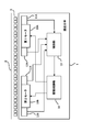
- FIG. 1 is a block diagram showing a mobile system according to the present embodiment.
- the mobile system shown in FIG. 1 is a system that uses a ground-type secondary linear motor.
- This moving body system includes a transport carriage 1 as a moving body and a track (rail) 2 as a moving path of the moving body.
- S-pole and N-pole magnets 3 are alternately arranged in a line at a predetermined pitch.
- the moving body system shown in FIG. 1 is a system of an overhead traveling vehicle in which the transport carriage 1 travels along a track 2 installed on the ceiling, for example.
- a moving body system is assumed in which the track 2 is several kilometers and the transport cart 1 is 300 to 400.
- the moving body in this embodiment is not limited to the conveyance carriage 1, and may be a carriage other than the conveyance carriage 1 or a movement body such as a robot arm.
- the transport carriage 1 includes two motors (first motor 10A, second motor 10B), two magnet non-detection sensors (first magnet non-detection sensor 11A, second magnet non-detection sensor 11B), and two position detections. Sensors (first position detection sensor 12 ⁇ / b> A, second position detection sensor 12 ⁇ / b> B), a control unit 13, and a drive control unit 14 are provided.
- the first motor 10 ⁇ / b> A and the second motor 10 ⁇ / b> B are linear motors that change the magnetic field so that the magnetic angles and the electrical angles of the S-pole and N-pole magnets 3 arranged alternately on the track 2 are synchronized.
- a three-phase (U, V, W phase) linear synchronous motor is used as the linear motor.
- the first motor 10A and the second motor 10B are arranged at different positions in the moving direction of the transport carriage 1 (the direction of the track 2 shown in FIG. 1). Further, the first motor 10 ⁇ / b> A and the second motor 10 ⁇ / b> B are respectively disposed at positions facing the magnet 3 on the track 2 in the transport carriage 1 and close to the magnet 3.
- the first motor 10 ⁇ / b> A is provided at a front position with respect to the traveling direction of the transport carriage 1, and the second motor 10 ⁇ / b> B is provided at a rear position with respect to the traveling direction of the transport carriage 1.
- the front with respect to the traveling direction is called the front, and the rear with respect to the traveling direction is called the rear.
- the first magnet non-detection sensor 11A and the second magnet non-detection sensor 11B are detection units that detect the magnet 3 on the track 2, respectively.
- the first magnet non-detection sensor 11 ⁇ / b> A is a detection unit for detecting that the first motor 10 ⁇ / b> A is located in a section (irregular section shown in FIG. 3) where the magnet 3 is not disposed on the track 2.
- the second magnet non-detection sensor 11B is a detection unit for detecting that the second motor 10B is located in a section (irregular section shown in FIG. 3) where the magnet 3 in the track 2 is not arranged. is there.
- the first magnet non-detection sensor 11A and the second magnet non-detection sensor 11B detect an object (a magnet 3 having S and N poles in FIG. 1) by receiving light emitted from the light emitting element with a light receiving element, for example. It is composed of a photo sensor.
- the first magnet non-detection sensor 11 ⁇ / b> A and the second magnet non-detection sensor 11 ⁇ / b> B are also arranged at positions that face the magnet 3 on the track 2 in the transport carriage 1 and close to the magnet 3.
- the first magnet non-detection sensor 11 ⁇ / b> A and the second magnet non-detection sensor 11 ⁇ / b> B each output a detection signal to the control unit 13.
- the first position detection sensor 12 ⁇ / b> A and the second position detection sensor 12 ⁇ / b> B are position detection units that detect the position of the transport carriage 1 on the track 2.
- the first position detection sensor 12A is located in a section (a section other than the irregular section shown in FIG. 11) in which the magnet 3 is disposed on the track 2, based on the detection position of the first position detection sensor 12A.
- the position of the transport carriage 1 is specified.
- the first position detection sensor 12A is located in a section (irregular section shown in FIG. 11) where the magnet 3 in the track 2 is not arranged, the first position detection sensor 12A is transported based on the detection position of the second position detection sensor 12B.
- the position of the carriage 1 is specified.
- the first position detection sensor 12A and the second position detection sensor 12B are, for example, magnetic pole detection sensors using Hall effect elements (magnetic conversion elements, hereinafter simply referred to as “Hall elements”).
- the first position detection sensor 12A and the second position detection sensor 12B are provided with a hall element in the detection head. And if a detection head moves relatively with respect to the magnet 3 with the movement of the conveyance trolley
- the first position detection sensor 12 ⁇ / b> A and the second position detection sensor 12 ⁇ / b> B are also arranged at positions that face the magnet 3 on the track 2 in the transport carriage 1 and are close to the magnet 3.
- the first position detection sensor 12 ⁇ / b> A and the second position detection sensor 12 ⁇ / b> B each output a detection signal to the control unit 13.
- the control unit 13 determines whether or not the first motor 10A is located in an irregular section based on the detection signal from the first magnet non-detection sensor 11A. When the control unit 13 determines that the first motor 10A is not located in the irregular section, the control unit 13 outputs a drive-on command that instructs the drive control unit 14 to drive the first motor 10A. Further, when the drive control unit 14 determines that the first motor 10A is located in an irregular section, the drive control unit 14 outputs a drive-on command that instructs the drive control unit 14 to stop driving the first motor 10A. To do. Similarly, the control unit 13 determines whether or not the second motor 10B is located in an irregular section based on the detection signal from the second magnet non-detection sensor 11B.
- the control unit 13 determines that the second motor 10B is not located in the irregular section, the control unit 13 outputs a drive-on command that instructs the drive control unit 14 to drive the second motor 10B. Further, when the drive control unit 14 determines that the second motor 10B is located in an irregular section, the drive control unit 14 outputs a drive-on command that instructs the drive control unit 14 to stop driving the second motor 10B. To do.
- the drive-on command indicates that the motors 10A and 10B are driven when the signal level is high (on state), and that the motors 10A and 10B are driven when the signal level is low level (off state). This is shown (see FIG. 6).
- the control unit 13 determines the position of the transport carriage 1 based on the detection signal from the first position detection sensor 12A.
- the control unit 13 specifies the position of the transport carriage 1 based on the detection signal from the second position detection sensor 12B. Then, the control unit 13 outputs a position command instructing to move the transport carriage 1 to the movement position based on the specified position of the transport carriage 1 to the drive control unit 14.
- the drive control unit 14 controls to drive or stop the first motor 10A in response to a drive-on command for the first motor 10A from the control unit 13.
- the drive control unit 14 controls driving or stopping of the second motor 10B in response to a drive-on command for the second motor 10B from the control unit 13.
- the drive control unit 14 performs drive control of the first motor 10A and the second motor 10B so that the transport carriage 1 moves to the movement position based on the position command from the control unit 13.
- the first magnet non-detection sensor 11A and the first position detection sensor 12A are provided at positions close to the first motor 10A, but may not be provided at such positions.
- the second magnet non-detection sensor 11B and the second position detection sensor 12B are provided at positions close to the second motor 10B, but need not be provided at such positions.
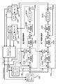
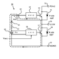
- FIG. 2 is a block diagram showing an internal configuration of the control unit and the drive control unit.
- the control unit 13 illustrated in FIG. 1 includes a position controller 131, a magnetless controller 132, and a motion controller 133.
- the drive control unit 14 shown in FIG. 1 includes a first drive control unit 14A that executes drive control of the first motor 10A and a second drive control unit 14B that executes drive control of the second motor 10B.
- MMD magnetless detection
- PS position detection sensors 12A and 12B.
- the position controller 131 determines whether or not the first motor 10A is located in an irregular section based on the detection signal from the first magnet non-detection sensor 11A.
- the magnet controller 132 sends a magnet non-detection state signal (“MLD-status” in FIG. 2) indicating the state. And output to the motion controller 133.
- the position controller 131 determines whether or not the second motor 10B is located in an irregular section based on the detection signal from the second magnet non-detection sensor 11B.
- the position controller 131 outputs a magnet non-detection signal indicating the state to the magnetless controller 132 and the motion controller 133.
- the position controller 131 determines the position of the transport carriage 1 based on the detection signal from the first position detection sensor 12A. Further, the position controller 131 specifies the position of the transport carriage 1 based on the detection signal from the second position detection sensor 12B when the first position detection sensor 12A is located in an irregular section. Then, the position controller 131 outputs position information indicating the current position of the identified transport carriage 1 to the motion controller 133, the first drive control unit 14A, and the second drive control unit 14B.
- the magnetless controller 132 drives / stops the first motor 10A with respect to the first drive control unit 14A based on the magnet non-detection signal for the first motor 10A from the position controller 131 (drive on / off). Outputs a drive-on command to indicate Further, the magnetless controller 132 instructs the second drive control unit 14B to drive / stop the second motor 10B based on the magnet non-detection signal for the second motor 10B from the position controller 131. Outputs a command.
- the motion controller 133 determines whether the first motor 10A and the second motor 10B are located in an irregular section based on the magnet non-detection signal from the position controller 131. Further, the motion controller 133 confirms the current position of the transport carriage 1 based on the position information from the position controller 131. Then, the motion controller 133 moves the conveyance carriage 1 to a predetermined position (movement position to move the conveyance carriage 1) with respect to the drive control units 14A and 14B of the motors 10A and 10B not located in the irregular section. A position command indicating that it is moved to is output.
- the first drive control unit 14A is provided with a position control unit 141A, a differentiator 142A, a speed control unit 143A, a current control unit 144A, an inverter 145A, and a coil 146A.
- the position control unit 141 ⁇ / b> A receives data (difference position data) as a difference amount between the movement position indicated by the position command from the motion controller 133 and the current position indicated by the position information from the position controller 131.
- position control part 141A outputs speed data according to difference position data.
- the speed control unit 143A receives difference amount data (differential speed data) between the speed data from the position control unit 141A and the data obtained by differentiating the position information from the position controller 131 in the differentiator 142A. Then, the speed control unit 143A outputs current value data corresponding to the differential speed data.
- the current control unit 144A includes current value data from the speed control unit 143A and feedback data corresponding to the current current value from the coil (load) 146A (that is, both ends of the resistor that detects the current supplied to the coil 146A).
- the difference amount data (differential current value data) from the actual current signal fed back based on the voltage is input.
- the current control unit 144A outputs a drive current corresponding to the differential current value data.
- the inverter 145A is a device that converts the DC drive current from the current control unit 144A into an AC drive current.
- This inverter 145A is a three-phase inverter using IPM (Intelligent Power Module).
- the AC drive current converted by the inverter 145A is output to the first motor 10A.
- the second drive control unit 14B is provided with a position control unit 141B, a differentiator 142B, a speed control unit 143B, a current control unit 144B, an inverter 145B, and a coil 146B.
- a position control unit 141B a differentiator 142B
- a speed control unit 143B a speed control unit 143B
- a current control unit 144B a current control unit 144B
- an inverter 145B an inverter 145B
- a coil 146B since the structure of each part in the 2nd drive control part 14B is the same as that of 14 A of 1st drive control parts, description is abbreviate
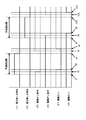
- FIG. 3 is a diagram for explaining an irregular section on the orbit, in which (A) is a diagram showing a state in which the first magnet non-detection sensor 11A is not positioned in the irregular section. These are figures which show the state in which 11 A of 1st magnet non-detection sensors are located in an irregular area.
- a magnet unit 3 ⁇ / b> U in which two combinations (a total of four magnets 3) of N-pole magnets 31 and S-pole magnets 32 are arranged on the track 2. ing.
- the work burden on the worker is greatly reduced as compared to installing the magnets 3 one by one.
- the “irregular section” refers to a section in which the magnetic poles are not regularly arranged, that is, a section in which the N pole magnet 31 and the S pole magnet 32 are not regularly arranged.
- the “irregular section” is not limited to a section in which the magnet 3 is not disposed, but also includes a section in which the N-pole magnet 31 and the S-pole magnet 32 are not alternately disposed.
- the area where the magnetic force of the magnet 3 is weak is included. And control which stops the drive of motor 10A, 10B is performed also in such an area.
- the transport carriage 1 when one of the two motors 10A and 10B (for example, the first motor 10A) is located in an irregular section where the arrangement of the magnetic poles of the magnet 3 is not regular, other than the one motor.
- the other motor for example, the second motor 10B
- the other motor is configured to be located in a section that is not an irregular section. That is, the irregular section is shorter than the distance between the motors (for example, between the two motors 10A and 10B) arranged at both ends in the movement direction among the plurality of motors. According to such a configuration, even when one motor is located in an irregular section, the transport carriage 1 can be moved by driving another motor.
- the distance between the irregular sections must be shorter than the distance between at least two motors 10A and 10B. Therefore, when the distance between the two motors 10A and 10B is known in advance, the irregular section is set to a distance shorter than that distance.
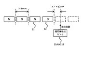
- FIG. 4 is a diagram showing the detection position of the irregular section by the magnet non-detection sensor.
- the pitch in the moving direction of the transport carriage 1 in one magnet 3 (N pole magnet 31 and S pole magnet 32) is set to 33 mm.
- the non-magnet detection sensors 11A and 11B are configured such that the magnet 3 is not disposed at least until the detection position of the magnet 3 becomes 1/4 pitch of the magnet 3 from the position where the magnet 3 is lost, that is, in an irregular section. Detects entry.
- the magnet non-detection sensors 11A and 11B determine whether or not the motors 10A and 10B are positioned in irregular sections
- the positions of the magnet non-detection sensors 11A and 11B and the positions of the motors 10A and 10B are determined. Is preferably at or near the same position.
- the distance between the positions of the non-magnet detection sensors 11A and 11B and the positions of the motors 10A and 10B is known in advance, the time when the non-magnet detection sensors 11A and 11B enter an irregular section based on the distance. It is possible to predict the time from when the motor 10A, 10B enters the irregular section to the current speed of the transport carriage 1.
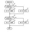
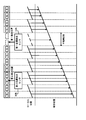
- FIG. 5 is a flowchart showing drive command processing by the control unit.
- FIG. 6 is a timing chart showing the relationship between detection of no magnet and driving of the motor. In FIG. 6, (F) means front (front), and (R) means rear (rear).
- the control unit 13 constantly confirms the detection signal from the first magnet non-detection sensor 11A (step S1). Then, when the first magnet non-detection sensor 11A does not detect the absence of a magnet (NO in step S1), the control unit 13 continuously drives the first motor 10A (step S2). That is, the control unit 13 continuously outputs a drive-on command that instructs the first drive control unit 14A to drive the first motor 10A.
- step S3 the control unit 13 stops driving the first motor 10A (step S3). That is, the control unit 13 outputs a drive-on command that instructs the first drive control unit 14A to stop driving the first motor 10A.
- the control unit 13 determines that the first magnet non-detection sensor 11A has not detected the absence of a magnet because the detection signal from the first magnet non-detection sensor 11A is at a low level until time t1 in FIG. At this time, the control unit 13 outputs a drive-on command that instructs the first drive control unit 14A to drive the first motor 10A. As shown in FIG. 6, the drive-on command for instructing driving is a high level signal. When time t1 in FIG. 6 is reached, the detection signal from the first magnet non-detection sensor 11A changes from the low level to the high level.
- the control unit 13 determines that the first magnet non-detection sensor 11A has detected the absence of a magnet.
- the control unit 13 then outputs a drive-on command that instructs the first drive control unit 14A to stop driving the first motor 10A.
- the drive-on command for instructing driving is a low level signal.
- the time from time t1 to time t2 in FIG. 6 is a time lag time from when the control unit 13 determines that the detection signal has changed to high level to when the drive-on command is changed to low level.
- the first motor 10A enters the irregular section from the time when the first magnet non-detection sensor 11A enters the irregular section. It is the time to the point.
- the first drive control unit 14 ⁇ / b> A controls the first motor 10 ⁇ / b> A from being driven to being stopped based on the drive-on command from the control unit 13.
- the driving ON state of the first motor 10A is at a high level, and the driving OFF state is at a low level.
- the time from time t2 to time t3 in FIG. 6 is a time lag time from when the first drive control unit 14A determines that the drive-on command has changed to a low level until the first motor 10A is actually stopped.
- the detection signal from the first magnet non-detection sensor 11A changes from the high level to the low level.
- the control part 13 determines with 11 A of 1st magnet non-detection sensors not detecting the absence of a magnet.
- the control unit 13 outputs a drive-on command that instructs the first drive control unit 14A to drive the first motor 10A.
- the time from time t4 to time t5 in FIG. 6 is a time lag time from when the control unit 13 determines that the detection signal has changed to low level to when the drive-on command is changed to high level.
- the motors 10A and 10B exit from the irregular section from the time when the magnet non-detection sensors 11A and 11B exit from the irregular section. It is the time to the point.
- the first drive control unit 14 ⁇ / b> A controls the drive of the first motor 10 ⁇ / b> A from the stopped state based on the drive-on command from the control unit 13.
- the time from time t5 to time t6 in FIG. 6 is a time lag time from when the first drive control unit 14A determines that the drive-on command has changed to a high level until the first motor 10A is actually driven.
- control unit 13 always confirms the detection signal from the second magnet non-detection sensor 11B (step S4). And the control part 13 drives the 2nd motor 10B continuously, when the 2nd magnet non-detection sensor 11B has not detected the absence of a magnet (NO of step S4) (step S5). That is, the control unit 13 continuously outputs a drive-on command that instructs the second drive control unit 14B to drive the second motor 10B.
- step S4 when the second magnet non-detection sensor 11B detects the absence of a magnet (YES in step S4), the control unit 13 stops driving the second motor 10B (step S5). That is, the control unit 13 outputs a drive-on command that instructs the second drive control unit 14B to stop driving the second motor 10B.
- the control unit 13 determines that the second magnet non-detection sensor 11B has not detected the absence of a magnet because the detection signal from the second magnet non-detection sensor 11B is at a low level until time t7 in FIG. At this time, the control unit 13 outputs a drive-on command that instructs the second drive control unit 14B to drive the second motor 10B. At time t7 in FIG. 6, the detection signal from the second magnet non-detection sensor 11B changes from the low level to the high level. Thereby, the control part 13 determines with the 2nd magnet non-detection sensor 11B having detected the absence of a magnet.
- the control unit 13 outputs a drive-on command that instructs the second drive control unit 14B to stop driving the second motor 10B.
- the time from time t7 to time t8 in FIG. 6 is a time lag time from when the control unit 13 determines that the detection signal has changed to high level to when the drive-on command is changed to low level.
- the second motor 10B enters the irregular section from the time when the second magnet non-detection sensor 11B enters the irregular section. It is the time to the point.
- the second drive control unit 14B controls the second motor 10B from being driven to being stopped based on the drive-on command from the control unit 13. As shown in FIG. 6, the driving ON state of the second motor 10B is at a high level, and the driving OFF state is at a low level.
- the time from time t8 to time t9 in FIG. 6 is a time lag time from when the second drive control unit 14B determines that the drive-on command has changed to a low level until the second motor 10B is actually stopped.
- the detection signal from the second magnet non-detection sensor 11B changes from the high level to the low level.
- the control part 13 determines with the 2nd magnet non-detection sensor 11B not detecting the absence of a magnet.
- the control part 13 outputs the drive ON command which instruct
- the time from time t10 to time t11 in FIG. 6 is a time lag time from when the control unit 13 determines that the detection signal has changed to low level to when the drive-on command is changed to high level.
- the second motor 10B exits from the irregular section from the time when the second magnet non-detection sensor 11B exits from the irregular section. It is the time to the point.
- the second drive control unit 14B controls the drive of the second motor 10B from the stopped state based on the drive-on command from the control unit 13 to the driven state.
- the time from time t11 to time t12 in FIG. 6 is a time lag time from when the second drive control unit 14B determines that the drive-on command has changed to a high level until the second motor 10B is actually driven.
- the control unit 13 stops driving the first motor 10A or the second motor 10B. Therefore, when the first motor 10A or the second motor 10B is located in an irregular section, the first motor 10A or the second motor 10B and the magnet 3 are prevented from being out of synchronization.
- the control unit 13 starts driving the first motor 10A or the second motor 10B. That is, when the first motor 10A or the second motor 10B moves to the regular section (when the irregular section ends), the control unit 13 outputs a drive-on command to the drive control unit 14 and newly adds a position command. Is output to the drive control unit 14. Thereby, the drive control part 14 synchronizes with the position of the magnet 3, and performs drive control of the 1st motor 10A or the 2nd motor 10B. Therefore, after the first motor 10A or the second motor 10B passes through the irregular section, the electrical angle of the first motor 10A or the second motor 10B and the magnetic pole of the magnet 3 are prevented from becoming out of synchronization.
- the driving of the first motor 10A or the second motor 10B is not started from the position of the first magnet 3 in the regular section after the irregular section is finished, but several first magnets 3 in the regular section are started.
- the driving of the first motor 10A or the second motor 10B may be started from the position of the magnet 3. Specifically, when the first magnet non-detection sensor 11A or the second magnet non-detection sensor 11B continuously detects several magnets 3 in the regular section, the control unit 13 turns on the drive control unit 14 to drive on. A command may be output and a new position command may be output to the drive control unit 14.
- the control unit 14 may restart the driving of the first motor 10A or the second motor 10B that has been stopped.
- the first magnet non-detection sensor 11A or the second magnet non-detection sensor 11B detects the irregular section and then detects a plurality of magnets continuously from the first magnet 3 in the regular section, it stops.
- the driving of the first motor 10A or the second motor 10B that has been performed may be resumed. According to such a configuration, the electrical angle of the first motor 10A or the second motor 10B and the position of the magnet 3 can be reliably synchronized at the start of the regular section.
- FIG. 7 is a circuit diagram showing a configuration of a bootstrap circuit mounted on the inverter.
- Inverters 145A and 145B can be operated with a single power supply on one side for mounting a bootstrap circuit 50 to drive an IGBT (Insulated Gate Bipolar Transistor) in a normal circuit configuration. .
- IGBT Insulated Gate Bipolar Transistor
- the IGBT on one side is turned on to charge the capacitor (bootstrap capacitor).
- the capacitor is used as a driving power source on the opposite side.
- the capacitor is discharged when the IGBT on one side is turned off. For this reason, at the time of start-up, it is necessary to secure a sufficient charge time for charging the capacitor with the necessary charge during driving.
- the outputs of the inverters 145A and 145B are stopped in order to stop the driving of the motors 10A and 10B, and then the motors 10A and 10B are stopped. Is no longer in the irregular section, the outputs of the inverters 145A and 145B are started to drive the motors 10A and 10B (see FIG. 6). Therefore, in the present embodiment, high-speed starting from the stopped state is necessary.
- the circuit configuration of the bootstrap circuit 50 mounted on the inverter will be described.
- the bootstrap circuit 50 includes a bootstrap capacitor 60, a bootstrap diode (high voltage fast diode) 61, and a current limiting resistor 62.
- a collector terminal of a P-side IGBT 54 (hereinafter referred to as IGBT 54 or P-side IGBT 54) and a P terminal 51 for inputting a voltage Vcc are connected, and an emitter terminal of the IGBT 54 and an output terminal 53 for each phase (for example, U Terminal).
- An HVIC (High Voltage IC) 56 is connected to the gate terminal of the IGBT 54.
- a diode 55 for commutating a load current is connected between the collector terminal and the emitter terminal of the IGBT 54.
- the HVIC 56 is an IC circuit that directly drives the gate of the IGBT 54 on the high voltage side by an input signal of a microcomputer (in this embodiment, the microcomputers of the drive control units 14A and 14B).
- N-side IGBT 57 (hereinafter referred to as IGBT 57 or N-side IGBT 57) and the output terminal 53 of each phase are connected, and the emitter terminal of IGBT 57 and the N terminal 52 whose potential is ground level are connected. Yes.
- an LVIC (Low Voltage IC) 59 is connected to the gate terminal of the IGBT 57.
- a diode 58 for commutating the load current is connected between the collector terminal and the emitter terminal of the IGBT 57.
- the LVIC 59 is an IC circuit that directly drives the gate of the IGBT 57 on the low voltage side by an input signal of a microcomputer (in this embodiment, the microcomputers of the drive control units 14A and 14B).
- the bootstrap capacitor 60 is connected between the connection point on the input side of the HVIC 56 and the output terminal 53 of each phase. Further, a bootstrap diode 61 and a current limiting resistor 62 are connected in series between a connection point on the input side of the HVIC 56 and a connection point on the input side of the LVIC 59.
- the power source VD63 is a power source for driving the IGBT 57. The power source VD63 is connected between the collector terminal and the emitter terminal of the IGBT 57.
- the HVIC 56 turns on the IGBT 55 and the LVIC 59 turns off the IGBT 57, whereby the potential of the output terminal 53 of each phase becomes the potential of the Vcc level. Further, the HVIC 56 turns off the IGBT 55 and the LVIC 59 turns on the IGBT 57, whereby the potential of the output terminal 53 of each phase becomes the ground level potential.
- PWM Pulse ⁇ ⁇ Width Modulation
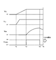
- FIG. 8 is a timing chart showing the relationship of each voltage during initial charging in the bootstrap circuit.
- the voltage Vcc gradually rises and the voltage VD rises.
- the pulse voltage VIN (N) is input from the microcomputer to the LVIC 59.
- the LVIC 59 drives the IGBT 57, and the IGBT 57 is turned on.
- the IGBT 57 is turned on, a current flows in a loop as shown in FIG. 7 and the bootstrap capacitor 60 is charged.
- the charging voltage VDB of the bootstrap capacitor 60 gradually increases.
- the IGBT 54 is turned on by driving the HVIC 56 at time T3
- the charge amount of the bootstrap capacitor 60 is used for driving the UGBT 54, and the charging voltage VDB gradually decreases.
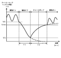
- FIG. 9 is a waveform diagram showing a voltage waveform of the bootstrap capacitor.
- the charging voltage VDB is required to be equal to or higher than the voltage Vmin.
- the charging voltage VDB of the bootstrap capacitor 60 gradually decreases. Thereafter, before the motor is turned on, the IGBT 57 is turned on, so that the charging voltage VDB of the bootstrap capacitor 60 gradually increases. Then, the driving of the inverters 145A and 145B is started from the time when the charging voltage VDB reaches the voltage value Vmin, and the motor is turned on.
- V2 G ( ⁇ 2, V1) due to the charge pump characteristics of the capacitor.
- the motor can be turned on. Therefore, the IGBT 54 can be reliably turned on in the shortest time by determining the charging time ⁇ 2 according to the driving time ⁇ 1 (the discharging time of the bootstrap capacitor 60).
- the time from when the P-side IGBT 57 is turned off until the charge pump is started is measured, and the charging time corresponding to the measured time is determined. calculate. Then, in the microcomputer or the like, the bootstrap capacitor 60 is charged with the calculated charging time.
- FIG. 10 is a flowchart showing position command processing by the control unit. As shown in FIG. 10, the control unit 13 constantly monitors the detection signals from the first position detection sensor 12A and the second position detection sensor 12B as described above. And the control part 13 pinpoints the present position of the conveyance trolley
- the control unit 13 determines whether or not the first position detection sensor 12A is located in an irregular section based on the detection signal from the first position detection sensor 12A (step S12). When it is determined that the first position detection sensor 12A is not located in the irregular section (NO in step S12), the control unit 13 determines the transport cart 1 based on the current position of the transport cart 1 specified in step S11. A position command for instructing the movement position is output to the drive control unit 14 (step S15). At this time, the motion controller 133 of the control unit 13 performs the first operation on the condition that the magnet non-detection state signal indicating that the first motor 10A is not located in the irregular section is input from the position controller 131. A position command is output to the drive control unit 14A. Similarly, on the condition that the motion controller 133 inputs a magnet non-detection state signal indicating that the second motor 10B is not located in an irregular section from the position controller 131, the second drive control unit 14B Position command is output to.
- the control unit 13 determines the conveyance carriage based on the detection signal from the second position detection sensor 12B. The moving distance of one irregular section is specified (step S13). And the control part 13 pinpoints the present position of the conveyance trolley 1 from the movement distance of the irregular area of the conveyance trolley 1 (step S14). Thereafter, the control unit 13 outputs a position command for instructing the moving position of the transport carriage 1 to the drive control unit 14 based on the current position of the transport carriage 1 specified in Step S14 (Step S15).
- FIG. 11 is a diagram for explaining complementary control of position detection by the second position detection sensor when the first position detection sensor is located in an irregular section.
- the control unit 13 determines the current state of the transport carriage 1 based on the detection signal from the first position detection sensor 12A in step S11.
- a position is specified (step S11).
- the first position detection sensor 12A outputs a detection signal corresponding to the voltage value from the hall element, which changes with the movement of the transport carriage 1, to the control unit 13 (here, the position controller 131). For example, when the transport carriage 1 is traveling at a constant speed, a detection signal that changes in the same cycle is output.
- the control unit 13 counts (that is, increments) the change in the detection signal from the first position detection sensor 12 ⁇ / b> A to identify the number of magnets 3 that the transport carriage 1 has passed, and thus identifies the position of the transport carriage 1.
- control unit 13 specifies one local position in a unit of a pair of N-pole magnet 31 and S-pole magnet 32, and adds (integrates) the local positions to thereby convey the carriage 1. Identify the integration location.
- whether or not the first position detection sensor 12A is located in the irregular section is performed by the following process. That is, the control unit 13 compares the change in the detection signal of the first position detection sensor 12A with the change in the detection signal of the second position detection sensor 12B, and detects when the change in the detection signals does not match. It is determined that one of the sensors 12A and 12B is located in the irregular section. And the control part 13 pinpoints which of detection sensor 12A, 12B is located in an irregular area from the advancing direction of the conveyance trolley
- the control unit 13 selects a position detection sensor used for specifying the position of the transport carriage 1.
- the first position detection sensor 12A is switched to the second position detection sensor 12B.
- the first position detection sensor 12A is located in the irregular section, but the second position detection sensor 12B is not located in the irregular section. Therefore, it is possible to specify the moving distance of the transport carriage 1 using the second position detection sensor 12B.
- the control unit 13 specifies the movement distance of the irregular section of the transport carriage 1 based on the detection signal from the second position detection sensor 12B (step S13), and the irregular section of the transport carriage 1 is identified.
- the current position of the transport carriage 1 is specified from the movement distance (step S14). That is, the control unit 13 counts (i.e., increments) the change in the detection signal from the first position detection sensor 12 ⁇ / b> A to identify the number of magnets 3 that the transport carriage 1 has passed, and sets the travel distance of the transport carriage 1 Identify.
- the control part 13 pinpoints the position of the conveyance trolley 1 by integrating the moving distance of the conveyance trolley 1 in the integrated position of the conveyance trolley 1.
- the position of the transport carriage 1 may be specified based on the distance between the first position detection sensor 12A and the second position detection sensor 12B. That is, the control unit 13 specifies the integrated position of the transport carriage 1 not only by the first position detection sensor 12A but also by the detection signal from the second position detection sensor 12B.
- the control unit 13 sets the first position detection sensor 12A and the second position at the integrated position of the transport carriage 1 based on the detection signal of the second position detection sensor 12B. The distance from the position detection sensor 12B is added. Thereby, the integrated position of the conveyance carriage 1 is specified by the detection signal of the first position detection sensor 12A.
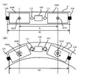
- FIG. 12 is a schematic diagram showing the bogie, where (A) shows the position of the bogie when the track is straight, and (B) shows the position of the bogie when the track is curved.
- the contact portion of the transport carriage 1 with the track 2 is constituted by a bogie truck provided with a mechanism that can rotate with respect to the vehicle body (not shown) of the transport carriage 1.
- FIG. 12 shows a case where the track 2 laid on the ceiling is viewed from below.
- the transport cart 1 includes two bogies 100A and 100B.
- the bogie bogie 100A is rotatably connected to the vehicle body of the transport bogie 1 by a center pin 101A.
- the bogie bogie 100B is rotatably connected to the vehicle body of the transport bogie 1 by a center pin 101B.
- the intermediate part 110 is disposed between the bogie bogie 100A and the bogie bogie 100B.
- Bogie bogie 100 ⁇ / b> A and intermediate portion 110 are connected by a connector 111.
- the bogie bogie 100B and the intermediate portion 110 are connected by a connector 112.
- the couplers 111 and 112 are also configured to be rotatable.
- the first position detection sensor 12A is attached to the surface of the bogie 100A opposite to the intermediate portion 110.
- the second position detection sensor 12B is attached to the surface opposite to the intermediate portion 110 in the bogie 100B.
- the bogies 100A and 100B are obtained when the track 2 is a straight line (FIG. 12A) and when the track 2 is a curve (FIG. 12B).
- the distance L between the center pins 101A and 101B does not change.
- the track 2 is a straight line (FIG. 12A) and when the track 2 is a curve (FIG. 12B)
- the distance to 110 changes. Accordingly, as shown in FIG. 12, the distance between the position detection sensors 12A and 12B changes between when the track 2 is a straight line (FIG.
- the controller 13 specifies the position of the magnet 3 by incrementing the detection signal from the first position detection sensor 12A, and specifies the position of the transport carriage 1 from the position of the magnet 3. ing. Therefore, even if the distance between the position detection sensors 12A and 12B changes, the transport carriage 1 can be used as long as the controller 13 does not make a mistake in the number of magnets 3 incremented based on the detection signal from the first position detection sensor 12A. The integrated position is not shifted from the original position.
- the moving body 1 has the two motors 10A and 10B arranged at different positions in the moving direction, and one of the two motors is the magnetic pole of the magnet 3.
- one of the two motors is the magnetic pole of the magnet 3.
- the transport carriage 1 can be normally driven even in a section where the magnet 3 is not disposed on the track 2.
- the irregular section includes a section where the S-pole and N-pole magnets are not alternately arranged, so that the transport cart 1 is normal even in a section where the magnets 3 are not regularly arranged alternately on the track 2. Can be driven.
- the transport carriage 1 since the transport carriage 1 includes the drive control unit 14 that stops the driving of the motors 10A and 10B located in the irregular section, the motors 10A and 10B and the magnetic pole of the magnet 3 cannot be synchronized in the irregular section. In addition, the motors 10A and 10B and the magnetic poles of the magnet 3 can be synchronized after the end of the irregular section.
- the transport carriage 1 includes detection units 11A and 11B that detect irregular sections, and the drive control unit 14 stops driving the motors 10A and 10B based on detection of the irregular sections by the detection units 11A and 11B. Therefore, it can be reliably detected that the motors 10A and 10B are located in the irregular section. Therefore, the driving of the motors 10A and 10B can be reliably stopped in the irregular section. Moreover, since detection part 11A, 11B is provided for every several motor, it can detect reliably that it is located in an irregular area about each of several motor 10A, 10B.
- the detection units 11A and 11B are optical sensors that detect the magnet 3, the irregular sections can be detected with high accuracy using light emission and light reception.
- the drive control unit 14 includes a bootstrap circuit 50, and the bootstrap capacitor 60 of the bootstrap circuit 50 is charged with a charging time corresponding to the time when the motors 10A and 10B are stopped. The driving of the motors 10A and 10B can be surely started.
- control unit 13 is based on the detection position of the second position detection unit 12B when the first position detection unit 12A is located in an irregular section where the arrangement of the magnetic poles of the magnet 3 is not regular.
- the exact position of the moving body 1 can be specified even when there is an irregular section where the position cannot be detected in the moving path 2.
- the position of the moving body 1 is detected by the second position detection unit 12B detecting the magnetic pole of the magnet 3, the position of the moving body 1 can be reliably specified in units of 3 magnets.
- the control unit 13 compares the detection position by the first position detection unit 12A with the detection position by the second position detection unit 12B, so that one of the first position detection unit 12A and the second position detection unit 12B. Since it is determined that one is located in the irregular section, it is possible to reliably specify that one of the first position detection unit 12A and the second position detection unit 12B is located in the irregular section. it can.
- the irregular section includes a section in which the magnet 3 is not disposed, the position of the moving body 1 can be reliably specified even in a section in which the magnet 3 is not disposed.
- the irregular section includes a section in which the S pole and N pole magnets 31 and 32 are not alternately arranged, so that the irregular section moves even in a section in which the S pole and N pole magnets 31 and 32 are not alternately arranged. The position of the body 1 can be specified reliably.
- the detection units 11A and 11B are configured by photosensors, but are not limited to such a configuration, and a Hall element is used.
- the magnetic pole detection sensor may be used.
- the Hall element of the magnetic pole detection sensor detects the irregular section by detecting the distortion (disturbance) of the magnetic field in the irregular section.
- the detection units 11A and 11B can detect the irregular section more reliably by the distortion of the magnetic field.
- the detection units 11A and 11B may be contact-type measuring devices (for example, measuring devices using probes).
- the detection units 12A and 12B are configured by the magnetic pole detection sensor that detects the magnetic pole, but the configuration is not limited thereto. Instead, it may be composed of a photosensor.
- the control part 13 specified the position of the magnet 3 by incrementing the detection signal from detection part 12A, 12B, and specified the position of the conveyance trolley
- the present invention is not limited to such a configuration, and the detection units 12A and 12B detect the absolute value of the movement distance of the transport carriage 1.
- control part 13 may be comprised so that the position of the conveyance trolley 1 may be specified based on the absolute value of the movement distance of the conveyance trolley 1 which detection part 12A, 12B detected.
- the absolute value (absolute position) of the movement distance of the transport carriage 1 may be detected by an encoder or the like.
- the detection unit includes a set of detection sensors (sensors), and detects the presence / absence of the magnet 3 in the irregular section (detection of the irregular section) and the position of the transport carriage 1 by this set of sensors. You may make it do. That is, the non-magnet detection sensors 11A and 11B and the position detection sensors 12A and 12B may be a common detection unit.
- control unit 13 determines that the first motor 10A is located in the irregular section based on the detection signal from the first detection unit, and determines the position of the transport carriage 1 based on the signal from the second detection unit. Is identified.
- the control unit 13 determines that the second motor 10B is located in the irregular section based on the detection signal from the second detection unit, and also determines the position of the transport carriage 1 based on the detection signal from the first detection unit. Is identified. According to such a configuration, the number of detection units is reduced, the cost is reduced, and the processing can be simplified.
- the position of the transport carriage 1 is specified using the second position detection sensor 12B. That is, the control unit 13 specifies the position of the transport carriage 1 based on the detection signal of the first position detection sensor 12A, and the second position only when the first position detection sensor 12A is located in an irregular section. Based on the detection signal of the detection sensor 12B, the position specification of the transport carriage 1 is supplemented.
- the configuration is not limited to such a configuration, and the control unit 13 specifies the local position and the integrated position based on the detection signals of the two position detection sensors 12A and 12B.
- the other integrated position is specified based on the detection signal of the position detection sensor not located in the irregular section. You may comprise so that it may complement. In this case, the position of the transport carriage 1 can be specified more reliably. Further, the position of the first motor 10A is specified by position detection by the first position detection sensor 12A corresponding to the first motor 10A, and the second position is detected by position detection by the second position detection sensor 12B corresponding to the second motor 10B. The position of the motor 10B can also be specified.
- the number of motors provided in the transport carriage 1 is two. However, three or more motors may be provided. Also in this case, when one motor among the plurality of motors is located in the irregular section, a motor other than the one motor among the plurality of motors is configured not to be located in the irregular section. . Further, in this case, it is preferable that a non-magnet detection sensor and a position detection sensor are provided for each motor.
- the two magnet non-detection sensors 11A and 11B are provided corresponding to the two motors 10A and 10B, only one magnet non-detection sensor may be provided.
- the controller 13 determines that the first motor 10A is located in the irregular section from the timing when the non-magnet detection sensor detects the irregular section and the distance between the non-magnet detection sensor and the first motor 10A. Specify the timing.
- the timing at which the second motor 10B is located in the irregular section is determined from the timing at which the magnet non-detection sensor detects the irregular section and the distance between the magnet non-detection sensor and the second motor 10B.
- the pitch in the moving direction of the motors 10A and 10B is assumed to be five times the pitch (33 mm) of the magnets 3, but is not limited to such a pitch.
- a mobile body system it is not restricted to the system using an overhead traveling vehicle, For example, the system to which a conveyance trolley moves along the track
- the two first position detection sensors 12A and 12B are attached to the transport carriage 1 (bogie carriages 100A and 100B).
- the present invention is not limited to such a case. It may be attached at other positions.
- a position detection sensor may be attached to the intermediate portion 110. In this case, since the intermediate part 110 is located in the middle of the bogies 100A and 100B, an accurate position of the transport carriage 1 (the center position of the transport carriage 1) is detected by a detection sensor attached to the intermediate part 110. be able to.
- the transport carriage 1 is moved by the thrust generated by the two motors 10A and 10B.
- the thrust by the two motors 10A and 10B is 100%, the thrust of one motor (the first motor 10A or the second motor 10B) is 50%.
- the thrust of the transport carriage 1 is reduced to 50% by stopping the motor.
- the time during which one of the two motors is located in the irregular section is short, the influence on the drive control of the transport carriage 1 is small.
- drive control may be performed so as to increase the thrust of the other motor.
- the thrust of the other motor may be controlled to 100% (twice) or a thrust close thereto. According to such a configuration, even when one of the two motors is located in an irregular section, the transport cart 1 can be driven without reducing the thrust.
Abstract
Description
図1は、本実施形態に係る移動体システムを示すブロック図である。図1に示す移動体システムは、地上二次式リニアモータを利用したシステムである。この移動体システムは、移動体としての搬送台車1と、移動体の移動経路としての軌道(レール)2とを備える。軌道2にはS極とN極の磁石3が交互に所定のピッチで一列に配置されている。なお、図1に示す移動体システムは、例えば天井に設置された軌道2に沿って搬送台車1が走行する天井走行車のシステムである。また、本実施形態では、軌道2が数Km、搬送台車1が300台~400台の移動体システムが想定されている。なお、本実施形態における移動体は搬送台車1に限定されず、搬送台車1以外の他の台車や、ロボットアーム等の移動体であってもよい。 Embodiments of the present invention will be described below with reference to the drawings.
FIG. 1 is a block diagram showing a mobile system according to the present embodiment. The mobile system shown in FIG. 1 is a system that uses a ground-type secondary linear motor. This moving body system includes a
図5は、制御部による駆動指令処理を示すフローチャートである。また、図6は、磁石無しの検出とモータの駆動との関係を示すタイミングチャートである。なお、図6において、(F)はフロント(前方)を意味し、(R)はリア(後方)を意味する。 (1) Motor drive control based on detection signals from the
FIG. 5 is a flowchart showing drive command processing by the control unit. FIG. 6 is a timing chart showing the relationship between detection of no magnet and driving of the motor. In FIG. 6, (F) means front (front), and (R) means rear (rear).
次に、駆動制御部14A,14Bのインバータ145A,145Bに実装されているブートストラップ回路の構成について説明する。図7は、インバータに実装されるブートストラップ回路の構成を示す回路図である。インバータ145A,145Bは、ブートストラップ回路50を実装することにより、通常の回路構成ではIGBT(Insulated Gate Bipolar Transistor)の駆動用にそれぞれ必要な電源を、一方側の電源1つで動作させることができる。モータの始動時に、一方側のIGBTをターンオンさせることによって、コンデンサ(ブートストラップコンデンサ)に電荷をチャージする。そして、駆動中はコンデンサを反対側の駆動用の電源として使用する。 (2) Bootstrap circuit operation:
Next, the configuration of the bootstrap circuit mounted on the
図10は、制御部による位置指令処理を示すフローチャートである。図10に示すように、制御部13は、上述したように、常時、第1位置検出センサ12A及び第2位置検出センサ12Bからの検出信号を監視している。そして、制御部13は、第1位置検出センサ12Aからの検出信号に基づいて搬送台車1の現在位置を特定する(ステップS11)。 (3) Position control based on detection signals of the
FIG. 10 is a flowchart showing position command processing by the control unit. As shown in FIG. 10, the
2 軌道(移動経路)
3 磁石
10A 第1モータ(モータ)
10B 第2モータ(モータ)
11A 第1磁石無検出センサ(検出部)
11B 第2磁石無検出センサ(検出部)
12A 第1位置検出センサ(第1位置検出部)
12B 第2位置検出センサ(第2位置検出部)
13 制御部
14 駆動制御部
31 N極の磁石
32 S極の磁石
50 ブートストラップ回路
60 ブートストラップコンデンサ 1 Transport cart (moving body)
2 orbit (movement route)
3
10B Second motor (motor)
11A 1st magnet non-detection sensor (detection part)
11B Second magnet non-detection sensor (detection unit)
12A 1st position detection sensor (1st position detection part)
12B 2nd position detection sensor (2nd position detection part)
DESCRIPTION OF
Claims (13)
- S極とN極の磁石を交互に配置した移動経路と、この移動経路に沿って移動する移動体とを備える移動体システムであって、
前記移動体は、移動方向において異なる位置に配置される複数のモータを有し、
前記複数のモータのうちの一のモータが前記磁石の磁極の配置が規則的でない不規則区間に位置したときに、前記一のモータ以外のモータのうちの少なくとも1つのモータが前記不規則区間でない区間に位置する
ことを特徴とする移動体システム。 A moving body system comprising a moving path in which S-pole and N-pole magnets are alternately arranged, and a moving body that moves along the moving path,
The moving body has a plurality of motors arranged at different positions in the moving direction,
When one of the plurality of motors is located in an irregular section where the arrangement of the magnetic poles of the magnet is not regular, at least one of the motors other than the one motor is not the irregular section. A mobile system characterized by being located in a section. - 前記不規則区間は、前記磁石が配置されていない区間であることを特徴とする請求項1に記載の移動体システム。 The mobile system according to claim 1, wherein the irregular section is a section in which the magnet is not arranged.
- 前記不規則区間は、前記S極とN極の磁石が交互に配置されていない区間であることを特徴とする請求項1に記載の移動体システム。 The mobile system according to claim 1, wherein the irregular section is a section in which the S-pole and N-pole magnets are not alternately arranged.
- 前記不規則区間は、前記複数のモータのうちの前記移動方向における両端に配置されるモータ間の距離よりも短いことを特徴とする請求項1~請求項3のうちいずれか1項に記載の移動体システム。 4. The irregular section according to claim 1, wherein the irregular section is shorter than a distance between motors arranged at both ends in the moving direction of the plurality of motors. Mobile body system.
- 前記移動体は、前記不規則区間に位置するモータの駆動を停止する駆動制御部を有することを特徴とする請求項1~請求項4のうちいずれか1項に記載の移動体システム。 The mobile system according to any one of claims 1 to 4, wherein the mobile body includes a drive control unit that stops driving of a motor located in the irregular section.
- 前記移動体は、前記不規則区間を検出する検出部を有し、
前記駆動制御部は、前記検出部による前記不規則区間の検出に基づいて前記モータの駆動を停止する
ことを特徴とする請求項5に記載の移動体システム。 The mobile body has a detection unit for detecting the irregular section,
The mobile system according to claim 5, wherein the drive control unit stops driving of the motor based on detection of the irregular section by the detection unit. - 前記検出部は、前記不規則区間に加えて、前記磁石の磁極の配置が規則的である規則区間を検出し、
前記駆動制御部は、前記検出部が前記不規則区間を検出した後に前記規則区間を検出した場合に、停止していた前記モータの駆動を再開することを特徴とする請求項6に記載の移動体システム。 In addition to the irregular section, the detection unit detects a regular section in which the magnetic poles of the magnet are regularly arranged,
The movement according to claim 6, wherein the drive control unit resumes driving of the motor that has been stopped when the detection unit detects the irregular section after detecting the irregular section. Body system. - 前記検出部は、前記磁石を検出することにより、前記不規則区間に加えて、前記磁石の磁極の配置が規則的である規則区間を検出し、
前記駆動制御部は、前記検出部が前記不規則区間を検出した後に、前記規則区間において最初の磁石から複数個の磁石を連続して検出した場合に、停止していた前記モータの駆動を再開することを特徴とする請求項7に記載の移動体システム。 The detection unit detects the magnet to detect a regular section in which the magnetic poles of the magnet are regularly arranged in addition to the irregular section,
The drive control unit resumes driving of the motor that has been stopped when the detection unit detects the irregular section and then detects a plurality of magnets continuously from the first magnet in the regular section. The mobile system according to claim 7, wherein: - 前記検出部は、前記複数のモータ毎に設けられることを特徴とする請求項6~請求項8のうちいずれか1項に記載の移動体システム。 The mobile system according to any one of claims 6 to 8, wherein the detection unit is provided for each of the plurality of motors.
- 前記検出部は、前記磁石を検出する光学式センサであることを特徴とする請求項6~請求項9のうちいずれか1項に記載の移動体システム。 The mobile system according to any one of claims 6 to 9, wherein the detection unit is an optical sensor that detects the magnet.
- 前記検出部は、1組のセンサで構成されるとともに、前記1組のセンサによって前記不規則区間と前記移動体の位置とを検出することを特徴とする請求項6~10のうちいずれか1項に記載の移動体システム。 11. The detection unit according to claim 6, wherein the detection unit includes a set of sensors and detects the irregular section and the position of the moving body by the set of sensors. The mobile system according to item.
- 前記駆動制御部は、ブートストラップ回路を含み、
このブートストラップ回路のブートストラップコンデンサは、前記モータを停止させた時間に応じた充電時間で充電される
ことを特徴とする請求項5~請求項11のうちいずれか1項に記載の移動体システム。 The drive control unit includes a bootstrap circuit,
The mobile system according to any one of claims 5 to 11, wherein the bootstrap capacitor of the bootstrap circuit is charged with a charging time corresponding to a time when the motor is stopped. . - S極とN極の磁石を交互に配置した移動経路に沿って移動する移動体の駆動方法であって、
前記移動体の移動方向において異なる位置に配置される複数のモータのうちの一のモータが前記磁石の磁極の配置が規則的でない不規則区間に位置しているときに、前記一のモータの駆動を停止することを特徴とする移動体の駆動方法。 A driving method of a moving body that moves along a moving path in which S-pole and N-pole magnets are alternately arranged,
Driving one motor when one of a plurality of motors arranged at different positions in the moving direction of the moving body is located in an irregular section where the magnetic poles of the magnet are not regularly arranged The moving body drive method characterized by stopping.
Priority Applications (6)
| Application Number | Priority Date | Filing Date | Title |
|---|---|---|---|
| US14/785,779 US9871478B2 (en) | 2013-04-22 | 2014-04-03 | Moving body system and method for driving moving body |
| CN201480022186.9A CN105142970B (en) | 2013-04-22 | 2014-04-03 | The driving method of movable body system and moving body |
| SG11201508622YA SG11201508622YA (en) | 2013-04-22 | 2014-04-03 | Moving body system and drive method of moving body |
| EP14788736.8A EP2990259B1 (en) | 2013-04-22 | 2014-04-03 | Moving body system and drive method of moving body |
| KR1020157030304A KR101900721B1 (en) | 2013-04-22 | 2014-04-03 | Moving body system and drive method of moving body |
| IL242191A IL242191B (en) | 2013-04-22 | 2015-10-20 | Moving body system and mdrive method of moving body |
Applications Claiming Priority (2)
| Application Number | Priority Date | Filing Date | Title |
|---|---|---|---|
| JP2013089408A JP6314371B2 (en) | 2013-04-22 | 2013-04-22 | MOBILE BODY SYSTEM AND MOBILE BODY DRIVING METHOD |
| JP2013-089408 | 2013-04-22 |
Publications (1)
| Publication Number | Publication Date |
|---|---|
| WO2014175032A1 true WO2014175032A1 (en) | 2014-10-30 |
Family
ID=51791613
Family Applications (1)
| Application Number | Title | Priority Date | Filing Date |
|---|---|---|---|
| PCT/JP2014/059843 WO2014175032A1 (en) | 2013-04-22 | 2014-04-03 | Moving body system and drive method of moving body |
Country Status (9)
| Country | Link |
|---|---|
| US (1) | US9871478B2 (en) |
| EP (1) | EP2990259B1 (en) |
| JP (1) | JP6314371B2 (en) |
| KR (1) | KR101900721B1 (en) |
| CN (1) | CN105142970B (en) |
| IL (1) | IL242191B (en) |
| SG (1) | SG11201508622YA (en) |
| TW (1) | TWI606941B (en) |
| WO (1) | WO2014175032A1 (en) |
Families Citing this family (7)
| Publication number | Priority date | Publication date | Assignee | Title |
|---|---|---|---|---|
| JP6206458B2 (en) * | 2015-08-21 | 2017-10-04 | 村田機械株式会社 | MOBILE BODY AND MOBILE BODY POSITION DETECTING METHOD |
| WO2017033578A1 (en) * | 2015-08-21 | 2017-03-02 | 村田機械株式会社 | Mobile body |
| JP6653179B2 (en) * | 2016-01-14 | 2020-02-26 | Thk株式会社 | Linear motor control device and control method |
| US10184813B2 (en) * | 2016-11-09 | 2019-01-22 | The Boeing Company | System and method for performing an automated inspection operation |
| US20190061558A1 (en) * | 2017-08-31 | 2019-02-28 | Rockwell Automation Technologies, Inc. | Systems and methods for sensing parameters on movers in linear motor systems |
| JP2021164396A (en) * | 2020-03-30 | 2021-10-11 | 住友重機械工業株式会社 | Linear motor transfer system and operation method therefor |
| US11774521B2 (en) * | 2021-01-20 | 2023-10-03 | Hiwin Mikrosystem Corp. | Position measuring mechanism and measuring method of linear motion system |
Citations (9)
| Publication number | Priority date | Publication date | Assignee | Title |
|---|---|---|---|---|
| JPS6115502A (en) * | 1984-06-29 | 1986-01-23 | Hitachi Ltd | Traveling passage of linear motor car |
| JPS61231805A (en) * | 1985-04-05 | 1986-10-16 | Hitachi Ltd | Frequency control system of linear motor type electric railcar |
| JPS6328203A (en) * | 1986-07-15 | 1988-02-05 | Railway Technical Res Inst | Position detector |
| JPH04295204A (en) * | 1991-03-25 | 1992-10-20 | Toshiba Corp | Traveling controller for linear motor car |
| JPH0993723A (en) * | 1995-09-28 | 1997-04-04 | Daifuku Co Ltd | Carryer facility utilizing linear motor |
| JPH11252970A (en) * | 1998-03-04 | 1999-09-17 | Matsushita Electric Ind Co Ltd | Power generator and electric washing machine therewith |
| JP2001186605A (en) * | 1999-10-13 | 2001-07-06 | Central Japan Railway Co | Vehicle propulsive device |
| JP2001204108A (en) * | 2000-01-19 | 2001-07-27 | Daifuku Co Ltd | Cargo transporting facility |
| JP2006027421A (en) | 2004-07-15 | 2006-02-02 | Asyst Shinko Inc | Transporting device using linear motor |
Family Cites Families (21)
| Publication number | Priority date | Publication date | Assignee | Title |
|---|---|---|---|---|
| JPS59201605A (en) | 1983-04-28 | 1984-11-15 | Hitachi Ltd | Controller for motor driven vehicle applied linear motor |
| JP2700686B2 (en) * | 1989-04-13 | 1998-01-21 | 株式会社ダイフク | Magnetic levitation type transfer equipment |
| US5130583A (en) * | 1989-11-13 | 1992-07-14 | Ricoh Company, Ltd. | Linear motor |
| JP2815655B2 (en) | 1989-11-17 | 1998-10-27 | 株式会社リコー | Moving magnet type linear motor |
| JP2783620B2 (en) * | 1989-11-13 | 1998-08-06 | 株式会社リコー | Moving coil type linear motor |
| US5175455A (en) * | 1990-10-31 | 1992-12-29 | Otis Elevator Company | Permanent magnet linear door motor |
| JP3436070B2 (en) * | 1997-05-15 | 2003-08-11 | 株式会社ダイフク | Transfer equipment |
| JP2000245128A (en) | 1999-02-22 | 2000-09-08 | Nkk Corp | Linear synchronous motor |
| JP3395155B2 (en) | 1999-05-07 | 2003-04-07 | 株式会社日立製作所 | Linear motor and manufacturing method thereof |
| JP2001112119A (en) | 1999-10-05 | 2001-04-20 | Toyota Autom Loom Works Ltd | Linear motor type conveyor |
| JP4239382B2 (en) * | 2000-08-24 | 2009-03-18 | 株式会社Ihi | Transport device |
| JP4084109B2 (en) * | 2002-07-05 | 2008-04-30 | 株式会社ソディック | Mobile drive unit |
| JP4813056B2 (en) * | 2004-07-29 | 2011-11-09 | パナソニック株式会社 | Mounting head for component mounting, and component mounting apparatus provided with the mounting head |
| US20090026848A1 (en) * | 2006-03-31 | 2009-01-29 | Houng Joong Kim | Linear motor |
| DE112008002447T5 (en) * | 2007-09-14 | 2010-07-22 | Thk Co., Ltd. | Linear motor and method for reducing screen phenomena |
| JP4941790B2 (en) * | 2009-08-28 | 2012-05-30 | 村田機械株式会社 | Mobile system |
| JP5486874B2 (en) | 2009-08-28 | 2014-05-07 | Thk株式会社 | Distributed linear motor and distributed linear motor control method |
| JP5421709B2 (en) * | 2009-09-30 | 2014-02-19 | Thk株式会社 | Linear motor drive system and control method |
| EP2537253B1 (en) * | 2010-02-18 | 2018-05-09 | Danfoss Drives A/S | Method for implementing bootstrap-supply charging in a motor controller at energized motor and motor controller using such a method |
| WO2012056841A1 (en) * | 2010-10-26 | 2012-05-03 | 村田機械株式会社 | Conveyance system |
| EP3150335B1 (en) * | 2011-06-02 | 2023-10-11 | Black & Decker, Inc. | Power tool with a control unit |
-
2013
- 2013-04-22 JP JP2013089408A patent/JP6314371B2/en active Active
-
2014
- 2014-04-03 CN CN201480022186.9A patent/CN105142970B/en active Active
- 2014-04-03 KR KR1020157030304A patent/KR101900721B1/en active IP Right Grant
- 2014-04-03 SG SG11201508622YA patent/SG11201508622YA/en unknown
- 2014-04-03 WO PCT/JP2014/059843 patent/WO2014175032A1/en active Application Filing
- 2014-04-03 EP EP14788736.8A patent/EP2990259B1/en active Active
- 2014-04-03 US US14/785,779 patent/US9871478B2/en active Active
- 2014-04-16 TW TW103113855A patent/TWI606941B/en active
-
2015
- 2015-10-20 IL IL242191A patent/IL242191B/en active IP Right Grant
Patent Citations (9)
| Publication number | Priority date | Publication date | Assignee | Title |
|---|---|---|---|---|
| JPS6115502A (en) * | 1984-06-29 | 1986-01-23 | Hitachi Ltd | Traveling passage of linear motor car |
| JPS61231805A (en) * | 1985-04-05 | 1986-10-16 | Hitachi Ltd | Frequency control system of linear motor type electric railcar |
| JPS6328203A (en) * | 1986-07-15 | 1988-02-05 | Railway Technical Res Inst | Position detector |
| JPH04295204A (en) * | 1991-03-25 | 1992-10-20 | Toshiba Corp | Traveling controller for linear motor car |
| JPH0993723A (en) * | 1995-09-28 | 1997-04-04 | Daifuku Co Ltd | Carryer facility utilizing linear motor |
| JPH11252970A (en) * | 1998-03-04 | 1999-09-17 | Matsushita Electric Ind Co Ltd | Power generator and electric washing machine therewith |
| JP2001186605A (en) * | 1999-10-13 | 2001-07-06 | Central Japan Railway Co | Vehicle propulsive device |
| JP2001204108A (en) * | 2000-01-19 | 2001-07-27 | Daifuku Co Ltd | Cargo transporting facility |
| JP2006027421A (en) | 2004-07-15 | 2006-02-02 | Asyst Shinko Inc | Transporting device using linear motor |
Non-Patent Citations (1)
| Title |
|---|
| See also references of EP2990259A4 |
Also Published As
| Publication number | Publication date |
|---|---|
| IL242191B (en) | 2019-01-31 |
| CN105142970A (en) | 2015-12-09 |
| KR20150132875A (en) | 2015-11-26 |
| KR101900721B1 (en) | 2018-09-20 |
| JP6314371B2 (en) | 2018-04-25 |
| EP2990259A1 (en) | 2016-03-02 |
| US20160072419A1 (en) | 2016-03-10 |
| US9871478B2 (en) | 2018-01-16 |
| CN105142970B (en) | 2018-06-26 |
| SG11201508622YA (en) | 2015-11-27 |
| EP2990259A4 (en) | 2016-12-14 |
| EP2990259B1 (en) | 2018-03-07 |
| TWI606941B (en) | 2017-12-01 |
| JP2014217076A (en) | 2014-11-17 |
| TW201446572A (en) | 2014-12-16 |
Similar Documents
| Publication | Publication Date | Title |
|---|---|---|
| JP6314372B2 (en) | POSITION DETECTION DEVICE, POSITION DETECTION METHOD, AND MOBILE BODY SYSTEM | |
| JP6314371B2 (en) | MOBILE BODY SYSTEM AND MOBILE BODY DRIVING METHOD | |
| KR101584022B1 (en) | Transfer system | |
| JP2011050200A (en) | Mobile system | |
| EP2599186B1 (en) | System and method for providing power to a moving element | |
| US11027615B2 (en) | System and method for improving travel across joints in a track for a linear motion system | |
| CN107848437B (en) | Moving body | |
| JP2012016106A (en) | Alignment system of noncontact power supply device | |
| JP6191665B2 (en) | Moving body | |
| US9768721B2 (en) | Mobile body and mobile body system | |
| JP3709779B2 (en) | Linear conveyor |
Legal Events
| Date | Code | Title | Description |
|---|---|---|---|
| WWE | Wipo information: entry into national phase |
Ref document number: 201480022186.9 Country of ref document: CN |
|
| 121 | Ep: the epo has been informed by wipo that ep was designated in this application |
Ref document number: 14788736 Country of ref document: EP Kind code of ref document: A1 |
|
| WWE | Wipo information: entry into national phase |
Ref document number: 2014788736 Country of ref document: EP |
|
| WWE | Wipo information: entry into national phase |
Ref document number: 242191 Country of ref document: IL Ref document number: 14785779 Country of ref document: US |
|
| ENP | Entry into the national phase |
Ref document number: 20157030304 Country of ref document: KR Kind code of ref document: A |
|
| NENP | Non-entry into the national phase |
Ref country code: DE |