WO2014174723A1 - Water treatment control device and water treatment system - Google Patents
Water treatment control device and water treatment system Download PDFInfo
- Publication number
- WO2014174723A1 WO2014174723A1 PCT/JP2013/083667 JP2013083667W WO2014174723A1 WO 2014174723 A1 WO2014174723 A1 WO 2014174723A1 JP 2013083667 W JP2013083667 W JP 2013083667W WO 2014174723 A1 WO2014174723 A1 WO 2014174723A1
- Authority
- WO
- WIPO (PCT)
- Prior art keywords
- water
- facility
- control device
- treatment
- water treatment
- Prior art date
Links
Images


Classifications
-
- E—FIXED CONSTRUCTIONS
- E03—WATER SUPPLY; SEWERAGE
- E03B—INSTALLATIONS OR METHODS FOR OBTAINING, COLLECTING, OR DISTRIBUTING WATER
- E03B3/00—Methods or installations for obtaining or collecting drinking water or tap water
- E03B3/04—Methods or installations for obtaining or collecting drinking water or tap water from surface water
-
- E—FIXED CONSTRUCTIONS
- E03—WATER SUPPLY; SEWERAGE
- E03B—INSTALLATIONS OR METHODS FOR OBTAINING, COLLECTING, OR DISTRIBUTING WATER
- E03B1/00—Methods or layout of installations for water supply
- E03B1/02—Methods or layout of installations for water supply for public or like main supply for industrial use
-
- G—PHYSICS
- G06—COMPUTING; CALCULATING OR COUNTING
- G06Q—INFORMATION AND COMMUNICATION TECHNOLOGY [ICT] SPECIALLY ADAPTED FOR ADMINISTRATIVE, COMMERCIAL, FINANCIAL, MANAGERIAL OR SUPERVISORY PURPOSES; SYSTEMS OR METHODS SPECIALLY ADAPTED FOR ADMINISTRATIVE, COMMERCIAL, FINANCIAL, MANAGERIAL OR SUPERVISORY PURPOSES, NOT OTHERWISE PROVIDED FOR
- G06Q10/00—Administration; Management
- G06Q10/08—Logistics, e.g. warehousing, loading or distribution; Inventory or stock management
- G06Q10/083—Shipping
- G06Q10/0832—Special goods or special handling procedures, e.g. handling of hazardous or fragile goods
-
- G—PHYSICS
- G06—COMPUTING; CALCULATING OR COUNTING
- G06Q—INFORMATION AND COMMUNICATION TECHNOLOGY [ICT] SPECIALLY ADAPTED FOR ADMINISTRATIVE, COMMERCIAL, FINANCIAL, MANAGERIAL OR SUPERVISORY PURPOSES; SYSTEMS OR METHODS SPECIALLY ADAPTED FOR ADMINISTRATIVE, COMMERCIAL, FINANCIAL, MANAGERIAL OR SUPERVISORY PURPOSES, NOT OTHERWISE PROVIDED FOR
- G06Q50/00—Systems or methods specially adapted for specific business sectors, e.g. utilities or tourism
- G06Q50/02—Agriculture; Fishing; Mining
-
- Y—GENERAL TAGGING OF NEW TECHNOLOGICAL DEVELOPMENTS; GENERAL TAGGING OF CROSS-SECTIONAL TECHNOLOGIES SPANNING OVER SEVERAL SECTIONS OF THE IPC; TECHNICAL SUBJECTS COVERED BY FORMER USPC CROSS-REFERENCE ART COLLECTIONS [XRACs] AND DIGESTS
- Y02—TECHNOLOGIES OR APPLICATIONS FOR MITIGATION OR ADAPTATION AGAINST CLIMATE CHANGE
- Y02A—TECHNOLOGIES FOR ADAPTATION TO CLIMATE CHANGE
- Y02A20/00—Water conservation; Efficient water supply; Efficient water use
- Y02A20/30—Relating to industrial water supply, e.g. used for cooling
Definitions
- Embodiments of the present invention relate to a water treatment control device that controls a water treatment facility, and a water treatment system that controls the water treatment facility based on a demand for water by a consumer.
- a water company takes water from a water source such as a river and treats the taken water to a drinking water level at a water purification plant facility.
- Water treated to the drinking water level is supplied to customers as tap water. Consumers use water in baths, washrooms, kitchens, washing machines, toilets, etc., and discharge the used water as drainage.
- the discharged waste water is treated to a certain water quality level at the sewage treatment plant and then discharged into the river.
- the water source is limited, and there may be a case where a sufficient amount of water cannot be secured during drought.
- tap water used by consumers is discharged as waste water, and the entire amount is treated at a sewage treatment plant, which raises a problem of increasing sewage treatment costs.
- the conventional water intake system may not be able to secure a sufficient amount of water during drought.
- the entire amount of waste water discharged by consumers has been treated at the sewage treatment plant, there is a problem that the cost of sewage treatment increases.
- an object is to provide a water treatment control device and a water treatment system that can secure the amount of water even during drought and can reduce the sewage treatment cost at the sewage treatment plant.
- the water treatment control device refers to the conditions including the drought situation and the water treatment cost of the water treatment facility, and includes a plurality of types including river water from the river, rainwater, and waste water after use by consumers. An instruction of the type of water taken by the water treatment facility is generated for the water treatment facility.
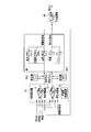
- FIG. 1 is a diagram illustrating a configuration of a water and sewage system including a water treatment facility according to the first embodiment.
- FIG. 2 is a diagram illustrating a configuration of the water treatment facility illustrated in FIG. 1.
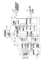
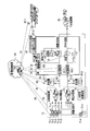
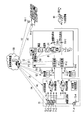
- FIG. 3 is a diagram illustrating a configuration of a water treatment system according to the second embodiment.
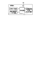
- FIG. 4 is a diagram illustrating a functional configuration of the monitoring control device illustrated in FIG. 3.
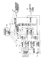
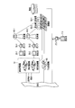
- FIG. 5 is a diagram illustrating a configuration of a water treatment system according to the third embodiment.
- FIG. 6 is a diagram illustrating a functional configuration of the monitoring control device illustrated in FIG. 5.
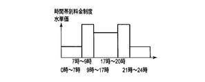
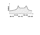
- FIG. 7 is a diagram showing the transition of the water unit price when the hourly rate system is adopted.
- FIG. 1 is a diagram illustrating a configuration of a water and sewage system including a water treatment facility according to the first embodiment.
- FIG. 2 is a diagram illustrating a configuration of the water treatment facility illustrated in FIG. 1.
- FIG. 3 is a diagram illustrating
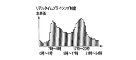
- FIG. 8 is a diagram showing the transition of the water unit price when adopting the real-time pricing system.
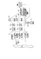
- FIG. 9 is a diagram illustrating a configuration of a water treatment system according to the fourth embodiment.
- FIG. 10 is a diagram illustrating a functional configuration of the monitoring control device illustrated in FIG. 9.
- FIG. 11 is a diagram illustrating a configuration of a water treatment system according to the fifth embodiment.
- FIG. 12 is a diagram illustrating a functional configuration of the monitoring control device illustrated in FIG. 11.
- FIG. 13 is a diagram illustrating a configuration of a water treatment system according to the sixth embodiment.
- FIG. 14 is a diagram illustrating a functional configuration of the monitoring control device illustrated in FIG. 13.
- FIG. 15 is a diagram illustrating a configuration of a water treatment system according to the seventh embodiment.
- FIG. 15 is a diagram illustrating a configuration of a water treatment system according to the seventh embodiment.
- FIG. 16 is a diagram illustrating a functional configuration of the monitoring control device illustrated in FIG. 15.
- FIG. 17 is a diagram showing a configuration of a water treatment system when the valves shown in FIGS. 13 and 15 are mounted for each facility in the home.
- FIG. 18 is a diagram illustrating a configuration of a water and sewage system including a water treatment system according to the eighth embodiment.
- FIG. 19 is a diagram illustrating a configuration of a water and sewage system including a water treatment system according to the eighth embodiment.
- FIG. 20 is a diagram illustrating a configuration of a water treatment system according to the eighth embodiment.
- FIG. 21 is a diagram illustrating a functional configuration of the monitoring control device illustrated in FIG. 20.
- FIG. 22 is a diagram illustrating a configuration of a water treatment system according to the ninth embodiment.
- FIG. 23 is a diagram illustrating a configuration of a water treatment system according to the tenth embodiment.
- 24 is a diagram illustrating a functional configuration of the monitoring control device illustrated in FIG.
- FIG. 25 is a diagram showing trends in water demand and drainage.
- FIG. 26 is a diagram illustrating a configuration of a water treatment system according to the eleventh embodiment.
- FIG. 27 is a diagram illustrating a functional configuration of the monitoring control device illustrated in FIG. 26.
- FIG. 28 is a diagram showing a tendency that the trend of the amount of drainage shown in FIG. 25 is flattened.
- FIG. 1 is a diagram illustrating a configuration of a water and sewage system including a water treatment facility 10 according to the first embodiment. 1 includes a water treatment facility 10, distribution reservoirs 20-1 and 20-2, pumps 30-1 and 30-2, distribution towers 40-1 and 40-2, and storage tanks 50-1 and 50. -It has a sewage treatment plant 60.
- FIG. 2 is a diagram showing the configuration of the water treatment facility 10 shown in FIG.
- a water treatment facility 10 illustrated in FIG. 2 includes a water purification plant facility 11, a reclaimed water facility 12, and a water treatment control device 13.
- the water purification plant facility 11 takes at least one of the river water from the river, well water, rain water, and clean drainage discharged by the customer in accordance with an instruction from the water treatment control device 13. Clean drainage will be described later.
- the water purification plant equipment 11 purifies the quality of the water taken up to the level of drinking water and sends it to the water supply line. Below, the water sent to a clean water line is called clean water.
- the reclaimed water facility 12 takes at least one of river water, well water, rainwater, and clean drainage in accordance with an instruction from the water treatment control device 13.
- the reclaimed water equipment 12 purifies the water quality of the taken water to a quality that can be used in a washing machine and a toilet, and sends the water to the middle water line. Below, the water sent to a middle water line is called middle water. Since the water quality level purified by the reclaimed water facility 12 is lower than the water quality level purified by the water purification plant facility 11, the treatment cost in the reclaimed water facility 12 can be reduced more than the treatment cost in the water purification plant facility 11.
- the water treatment control device 13 estimates the drought status of river water, well water and rain water from the season and weather, etc., the estimated drought status, the stockpiling amount in the storage tanks 50-1 and 50-2, the river water, the well water Referring to various conditions including treatment costs at the water purification plant facility 11 and the reclaimed water facility 12 for rainwater and clean wastewater, which water is to be taken and processed for the water purification plant facility 11 and the reclaimed water facility 12 Instruct. For example, in order to purify clean wastewater to the drinking water level at the water purification plant facility 11, the processing cost increases. Therefore, when it is not during drought, clean wastewater is taken in by the reclaimed water facility 12 and processed by the reclaimed water facility 12. Later, water will be sent to the middle water line.
- Water supplied from the water purification plant facility 11 to the water supply line is stored in the distribution reservoir 20-1, and is supplied to the distribution tower 40-1 by the pump 30-1. Water is supplied from the water distribution tower 40-1 to a water supply area where a plurality of consumers are present. When the amount of clean water supplied from the distribution tower 40-1 is large, the clean water is stored in the water tank 50-1.
- the middle water sent from the reclaimed water facility 12 to the middle water line is stored in the distribution reservoir 20-2 and sent to the distribution tower 40-2 by the pump 30-2.
- the middle water is supplied from the water distribution tower 40-2 to a water supply area where there are a plurality of consumers.
- the middle water is stored in the water storage tank 50-2.
- a plurality of facilities using water such as a bath, a washroom, a kitchen, a washing machine, and a toilet
- a plurality of facilities provided in a home have different water quality for each facility.
- baths, washrooms, and kitchens are required to have drinking water level water quality, and washing machines and toilets do not require water quality up to that level. Therefore, clean water is supplied to baths, washrooms, and kitchens, and medium water is supplied to washing machines and toilets.
- wastewater after use is separated according to the water quality level of the wastewater.
- water used in a bath, a washroom, and a kitchen is clean wastewater and is sent to the water treatment facility 10.
- the water used in the washing machine and toilet is dirty wastewater and is discharged to the sewage treatment plant 60.
- the sewage treatment plant 60 treats dirty wastewater discharged from the water supply area to a certain water quality level, and then discharges it to a river or the like. If the drought condition is serious, water used in the washing machine and toilet may be sent to the water treatment facility 10 as long as the water quality level is available as intermediate water.
- the water treatment control device 13 treats clean wastewater discharged by a consumer so that it can be reused by the reclaimed water facility 12.
- the number of water sources from which water can be taken increases, so that water can be supplied to consumers even when the river is drought.
- the water treatment control apparatus 13 since it becomes possible for the water treatment control apparatus 13 to reduce the processing load in the water purification plant equipment 11 and the sewage treatment plant 60 more than before, the scale of the water treatment plant equipment 11 and the sewage treatment plant 60 is made larger than before. It is possible to reduce the facility cost, and it is possible to reduce the facility cost and the operation cost of the treatment plant. In addition, by reducing the amount of water taken from the river, it is possible to reduce the cost of water intake rights paid by the water company.
- the amount of water can be secured even during drought and the sewage treatment cost at the sewage treatment plant can be reduced.
- FIG. 3 is a diagram illustrating a configuration of a water treatment system according to the second embodiment.
- 3A is water quality data (and water volume data) transmitted from the sensors 72-1 to 72-4
- FIG. 3B is water volume data transmitted from the sensors 51-1 and 51-2.
- C is water amount data of the water supply line transmitted from the sensor 81-1
- (d) is water amount data of the middle water line transmitted from the sensor 81-2
- (e) is an intake pump 71-
- F) is a control of water treatment given to the water treatment facility 70
- (g) is a storage control given to the water storage tanks 50-1 and 50-2. Water discharge control.
- the water treatment system shown in FIG. 3 includes a water treatment facility 70, water storage tanks 50-1 and 50-2, water volume sensors 81-1 and 81-2, and a monitoring control device 80.
- the water treatment facility 70 includes a water purification plant facility 11, a reclaimed water facility 12, a water treatment control device 13, water intake pumps 71-1 to 71-4, and sensors 72-1 to 72-4.
- the sensor 72-1 measures the water quality of the river water and transmits the acquired water quality data to the monitoring control device 80.
- the intake pump 71-1 takes river water in accordance with the control from the monitoring control device 80, and supplies the taken river water to the water purification plant facility 11 and / or the reclaimed water facility 12.
- the sensor 72-2 measures the water quality and amount of well water, and transmits the acquired water quality data and water amount data to the monitoring control device 80.
- the intake pump 71-2 takes well water in accordance with the control from the monitoring control device 80, and supplies the taken well water to the water purification plant facility 11 and / or the reclaimed water facility 12.
- the sensor 72-3 measures the quality of rainwater and transmits the acquired water quality data to the monitoring control device 80.
- the water intake pump 71-3 takes rainwater in accordance with the control from the monitoring control device 80, and supplies the taken rainwater to the water purification plant facility 11 and / or the reclaimed water facility 12.
- Sensor 72-4 measures the quality and quantity of clean wastewater, and transmits the acquired water quality data and quantity data to the monitoring control device 80.
- the water intake pump 71-4 takes clean wastewater according to the control from the monitoring control device 80, and supplies the clean water that has been taken up to the water purification plant facility 11 and / or the reclaimed water facility 12.
- the water storage tank 50-1 is provided with a sensor 51-1.
- the sensor 51-1 measures the amount of water in the water tank 50-1, and transmits the acquired water amount data to the monitoring control device 80.
- the water storage tank 50-1 stores water according to the water storage control from the monitoring control device 80.
- the water storage tank 50-1 discharges the stored water to the water supply line in accordance with the water discharge control from the monitoring control device 80.
- the water storage tank 50-2 is provided with a sensor 51-2.
- the sensor 51-2 measures the amount of water in the water storage tank 50-2 and transmits the acquired water amount data to the monitoring control device 80.
- the water storage tank 50-2 stores middle water in accordance with the water storage control from the monitoring control device 80. Further, the water storage tank 50-2 discharges the stored intermediate water to the intermediate water line in accordance with the discharge control from the monitoring control device 80.
- Sensor 81-1 is provided in the water supply line, and measures the amount of water supplied to the water supply area.
- the sensor 81-1 transmits the acquired water amount data to the monitoring control device 80.
- the sensor 81-2 is provided in the middle water line and measures the amount of middle water supplied to the water supply area.
- the sensor 81-2 transmits the acquired water amount data to the monitoring control device 80.
- the monitoring control device 80 is, for example, a cloud server constructed from a plurality of servers.
- the monitoring control device 80 is connected to the water treatment facility 70, the sensors 81-1 and 81-2, and the water storage tanks 50-1 and 50-2 through a network such as the Internet.
- the monitoring and control device 80 includes water quality data and water volume data transmitted from the sensors 72-1 to 72-4, water volume data transmitted from the sensors 51-1 and 51-2, and sensors 81-1 and 81-2. Receive the transmitted water volume data.
- the monitoring control device 80 includes a signal processing unit 82 as shown in FIG.
- the signal processing unit 82 includes, for example, a CPU (Central Processing Unit), and a storage area for programs and data for the CPU to execute processing such as ROM (Read Only Memory) and RAM (Random Access Memory).
- the signal processing unit 82 based on the water amount data transmitted from the sensors 81-1 and 81-2, first water demand data indicating the demand for clean water in the water supply area, and water in the middle water in the water supply area. Second water demand data indicating the demand is generated.
- the signal processing unit 82 determines the water amount of the water storage tanks 50-1 and 50-2 grasped from the sensors 51-1 and 51-2, and the water quality and the water amount of the water source grasped from the sensors 72-1 to 72-4.
- the water treatment cost in the water purification plant facility 11 and the reclaimed water facility 12 is minimized while satisfying the water demand indicated by the first and second water demand data.
- the signal processing unit 82 controls the water intake pumps 71-1 to 71-4, the water treatment control device 13, and the water storage tanks 50-1 and 50-2 so as to realize the determined processing amount.
- Water sources such as river water, well water, and rainwater constantly change in water volume and / or quality. For example, a lot of rainwater can be secured in the rainy season, but it becomes difficult to secure rainwater in the dry season. In addition, the rainwater in the time zone just after the rain is severely contaminated with dust, dust, etc., but the rainwater dirt improves after a certain period of time. Water treatment costs can be reduced by performing water treatment on water with less dirt than performing water treatment on water with severe dirt. Thus, it is effective to determine the amount of water to be treated based on the amount and quality of the water source.
- control which reduces water treatment cost in the water purification plant equipment 11 when water quality is higher than a predetermined level, control which reduces the quantity of the blower in the aerobic tank provided in the water purification plant equipment 11 is mentioned, for example. It is done.
- the water treatment control device 13 treats clean wastewater discharged by a consumer so that it can be reused by the reclaimed water facility 12. As a result, the number of water sources from which water can be taken increases, so that water can be supplied to consumers even when the river is drought. Moreover, since it becomes possible for the water treatment control apparatus 13 to reduce the processing load in the water purification plant equipment 11 and the sewage treatment plant 60 more than before, the scale of the water treatment plant equipment 11 and the sewage treatment plant 60 is made larger than before. It is possible to reduce the facility cost, and it is possible to reduce the facility cost and the operation cost of the treatment plant.
- the amount of water can be secured even during drought, and the sewage treatment cost at the sewage treatment plant can be reduced.
- the water treatment system according to the second embodiment includes water quality data and water volume data on water sources acquired by the sensors 72-1 to 72-4, and the water tank 50 acquired by the sensors 51-1 and 51-2.
- the water treatment facility 70 is controlled based on the water amount data of -1,50-2 and the water amount data in the water supply area acquired by the sensors 81-1, 81-2. Thereby, the processing cost in the water purification plant equipment 11 and the reclaimed water equipment 12 can be more efficiently reduced.
- FIG. 5 is a diagram illustrating a configuration of a water treatment system according to the third embodiment.
- (a) is water quality data (and water amount data) transmitted from the sensors 72-1 to 72-4, and (b) is water amount data transmitted from the sensors 51-1 and 51-2.
- (C) is water amount data of the water supply line transmitted from the sensor 81-1
- (d) is water amount data of the middle water line transmitted from the sensor 81-2
- (e) is an intake pump 71-
- F is a control of water treatment given to the water treatment facility 70
- (g) is a storage control given to the water storage tanks 50-1 and 50-2.
- Water discharge control (h) is water usage data uploaded from the measuring device 91-1, and (i) is medium water usage data uploaded from the measuring device 91-2.
- the water treatment system shown in FIG. 5 includes a water treatment facility 70, water storage tanks 50-1 and 50-2, water volume sensors 81-1 and 81-2, measuring devices 91-1 and 91-2, and a monitoring control device 90. .
- the measuring device 91-1 is, for example, a smart meter, and is installed in a water supply line in each household existing in the water supply area.
- the measuring device 91-1 measures the amount of clean water out of the amount of water used by consumers.
- the measuring device 91-1 uploads the measured usage amount as usage amount data to the monitoring control device 90 in real time.
- the measuring device 91-2 is, for example, a smart meter, and is installed in the middle water line in each household existing in the water supply area.
- the measuring device 91-2 measures the amount of medium water out of the amount of water used by consumers.
- the measuring device 91-2 uploads the measured usage amount as usage amount data to the monitoring control device 90 in real time.
- the monitoring control device 90 is, for example, a cloud server constructed from a plurality of servers.
- the monitoring control device 90 is connected to the water treatment facility 70, the sensors 81-1 and 81-2, the water storage tanks 50-1 and 50-2, and the home via a network such as the Internet.
- the monitoring control device 90 transmits the water quality data and water volume data transmitted from the sensors 72-1 to 72-4, the water volume data transmitted from the sensors 51-1 and 51-2, and the sensors 81-1 and 81-2. Water amount data and usage amount data transmitted from the measuring devices 91-1 and 91-2 are received.
- the monitoring control device 90 includes a signal processing unit 92 as shown in FIG.
- the signal processing unit 92 includes, for example, a CPU and a storage area for programs and data for the CPU to execute processing such as ROM and RAM.
- the signal processing unit 92 generates first water demand data indicating the demand for clean water in the water supply area based on the usage data transmitted from the measuring device 91-1 installed in each household.
- the signal processing unit 92 generates second water demand data indicating the demand for middle water in the water supply area based on the usage data transmitted from the measuring device 91-2 installed in each household. Further, when the first water demand data and the second water demand data are generated, it is possible to supplement the water amount data transmitted from the sensor 81-1 and the water amount data transmitted from the sensor 81-2. .
- the water amount data transmitted from the sensor has a larger value.
- the water demand data is generated using the usage amount data of the measuring device and the water amount data of the sensor. For example, it is possible to generate water demand data by referring to the relationship between past usage data and water data.
- the signal processing unit 92 determines the water amount of the water storage tanks 50-1 and 50-2 grasped from the sensors 51-1 and 51-2, and the water quality and the water amount of the water source grasped from the sensors 72-1 to 72-4. With reference to the water purification plant facility 11 and the reclaimed water facility 12, the water treatment cost in the water purification plant facility 11 and the reclaimed water facility 12 is minimized while satisfying the water demand indicated by the first and second water demand data. Determine the volume of river water, well water, rainwater and clean wastewater. The signal processing unit 92 controls the water intake pumps 71-1 to 71-4, the water treatment control device 13, and the water storage tanks 50-1 and 50-2 so as to realize the determined processing amount.
- the water treatment control device 13 treats clean wastewater discharged by a consumer so that it can be reused by the reclaimed water facility 12. As a result, the number of water sources from which water can be taken increases, so that water can be supplied to consumers even when the river is drought. Moreover, since it becomes possible for the water treatment control apparatus 13 to reduce the processing load in the water purification plant equipment 11 and the sewage treatment plant 60 more than before, the scale of the water treatment plant equipment 11 and the sewage treatment plant 60 is made larger than before. It is possible to reduce the facility cost, and it is possible to reduce the facility cost and the operation cost of the treatment plant.
- the amount of water can be secured even during drought, and the sewage treatment cost at the sewage treatment plant can be reduced.
- the water treatment system according to the third embodiment includes water quality data and water volume data on water sources acquired by the sensors 72-1 to 72-4, and the water tank 50 acquired by the sensors 51-1 and 51-2.
- the water treatment facility 70 is controlled based on the water amount data of -1,50-2 and the water usage data in each home acquired by the measuring devices 91-1, 91-2.
- the monitoring and control device 90 can grasp the water demand by water quality of each consumer in real time, so that the water treatment facility is adapted to the water demand in the water supply area that changes from moment to moment. 70 and the water storage tanks 50-1 and 50-2 can be optimally operated.
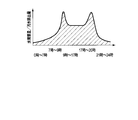
- the hourly rate system is a rate system that changes the unit price of water according to the time period and period (season etc.) based on past trends and the like, and the transition of the unit price of water is shown in FIG.
- the real-time pricing system is a charge system that changes the charge system according to the actual situation, and the transition of the water unit price is shown in FIG.
- FIG. 9 is a diagram showing a configuration of a water treatment system according to the fourth embodiment.
- (a) is water quality data (and water amount data) transmitted from the sensors 72-1 to 72-4, and (b) is water amount data transmitted from the sensors 51-1 and 51-2.
- (C) is water amount data of the water supply line transmitted from the sensor 81-1
- (d) is water amount data of the middle water line transmitted from the sensor 81-2
- (e) is an intake pump 71-
- F is a control of water treatment given to the water treatment facility 70
- (g) is a storage control given to the water storage tanks 50-1 and 50-2.
- the water treatment system shown in FIG. 9 includes a water treatment facility 70, water storage tanks 50-1 and 50-2, water volume sensors 81-1 and 81-2, measuring devices 91-1 and 91-2, a management terminal 101, and monitoring control.
- a device 100 is provided.
- the management terminal 101 is, for example, a home energy management system (HEMS) with a display unit, and is installed in each home existing in the water supply area.
- the management terminal 101 displays the first and second water unit price information given from the monitoring control device 100.
- 1st water unit price information represents the water unit price of clean water
- 2nd water unit price information represents the water unit price of middle water.
- a consumer uses the equipment with which a household is equipped with reference to the 1st and 2nd water unit price information displayed on the management terminal 101.
- FIG. For example, if a consumer determines that the unit price of clean water is high at the current time, he / she refrains from using a bath, a washroom, and the kitchen, and if the unit price of clean water is low at the current time, Use the equipment.
- the monitoring control device 100 is a cloud server constructed from a plurality of servers, for example.
- the monitoring control device 100 is connected to the water treatment facility 70, the sensors 81-1 and 81-2, the water storage tanks 50-1 and 50-2, and the home via a network such as the Internet.
- the monitoring and control apparatus 100 transmits water quality data and water amount data transmitted from the sensors 72-1 to 72-4, water amount data transmitted from the sensors 51-1 and 51-2, and transmitted from the sensors 81-1 and 81-2. Water amount data and usage amount data transmitted from the measuring devices 91-1 and 91-2 are received.
- the monitoring control device 100 includes a signal processing unit 102 as shown in FIG.
- the signal processing unit 102 includes, for example, a CPU and a storage area for programs and data for the CPU to execute processing such as ROM and RAM.
- the signal processing unit 102 generates first water demand data indicating the demand for clean water in the water supply area based on the usage data transmitted from the measuring device 91-1 installed in each household. Further, the signal processing unit 102 generates second water demand data indicating the demand for middle water in the water supply area based on the usage data transmitted from the measuring device 91-2 installed in each household.
- the signal processing unit 102 When the hourly rate system is adopted, the signal processing unit 102 generates the first water unit price information from the water unit price for the water supply set based on the past trend or the like, and generates the generated first water unit information. Water unit price information is transmitted to the management terminal 101 installed in each household. Further, the signal processing unit 102 generates second water unit price information from the water unit price for the middle water set based on past trends and the like, and transmits the generated second water unit price information to the management terminal 101. To do. Moreover, when the real-time pricing system is adopted, the signal processing unit 102 generates the first water unit price information based on the first water demand data, and the generated first water unit price information is sent to the management terminal 101. Send. Further, the signal processing unit 102 generates second water unit price information based on the second water demand data, and transmits the generated second water unit price information to the management terminal 101.
- the signal processing unit 102 determines the water amount of the water storage tanks 50-1 and 50-2 grasped from the sensors 51-1 and 51-2, and the water quality and the water amount of the water source grasped from the sensors 72-1 to 72-4. With reference to the water purification plant facility 11 and the reclaimed water facility 12, the water treatment cost in the water purification plant facility 11 and the reclaimed water facility 12 is minimized while satisfying the water demand indicated by the first and second water demand data. Determine the volume of river water, well water, rainwater and clean wastewater. The signal processing unit 102 controls the water intake pumps 71-1 to 71-4, the water treatment control device 13, and the water storage tanks 50-1 and 50-2 so as to realize the determined processing amount.
- the water treatment control device 13 treats clean wastewater discharged by a consumer so that it can be reused by the reclaimed water facility 12. As a result, the number of water sources from which water can be taken increases, so that water can be supplied to consumers even when the river is drought. Moreover, since it becomes possible for the water treatment control apparatus 13 to reduce the processing load in the water purification plant equipment 11 and the sewage treatment plant 60 more than before, the scale of the water treatment plant equipment 11 and the sewage treatment plant 60 is made larger than before. It is possible to reduce the facility cost, and it is possible to reduce the facility cost and the operation cost of the treatment plant.
- the amount of water can be secured even during drought, and the sewage treatment cost at the sewage treatment plant can be reduced.
- the water treatment system according to the fourth embodiment transmits first water unit price information about clean water and second water unit price information about middle water to the management terminal 101 installed in each home. .
- the management terminal 101 is displaying the 1st and 2nd water unit price information.
- FIG. 11 is a diagram illustrating a configuration of a water treatment system according to the fifth embodiment.
- A) in FIG. 11 is water quality data (and water volume data) transmitted from the sensors 72-1 to 72-4, and (b) is water volume data transmitted from the sensors 51-1 and 51-2.
- C) is water amount data of the water supply line transmitted from the sensor 81-1,
- (d) is water amount data of the middle water line transmitted from the sensor 81-2, and
- (e) is an intake pump 71-
- F is a control of water treatment given to the water treatment facility 70, and
- (g) is a storage control given to the water storage tanks 50-1 and 50-2.
- the water treatment system shown in FIG. 11 includes a water treatment facility 70, water storage tanks 50-1 and 50-2, water volume sensors 81-1 and 81-2, measuring devices 91-1 and 91-2, a management terminal 103, and monitoring control.
- a device 100 is provided.
- the management terminal 103 is, for example, a home energy management system, and is installed in each home in the water supply area.
- the management terminal 103 is provided with first water unit price information about clean water and second water unit price information about middle water from the monitoring control device 100.
- the management terminal 103 receives reservation settings for equipment such as a bath, a kitchen, and a washing machine installed in a home from a consumer.
- the reservation settings entered here include, for example, completing hot water by 0:00 in the evening, completing dishwashing by ⁇ at night, and washing by ⁇ in the morning. Completion and the like.
- the management terminal 103 includes a signal processing unit 1031 as shown in FIG.
- the signal processing unit 1031 includes, for example, a CPU and a storage area for programs and data for the CPU to execute processing such as ROM and RAM.
- the signal processing unit 1031 calculates an optimal time zone for operating the facility based on the first and second water unit price information transmitted from the monitoring control device 100 and the reservation setting input from the consumer.
- the signal processing unit 1031 performs on / off operation control on the home equipment so that the home equipment is operated in the calculated time zone.
- the water treatment control device 13 treats clean wastewater discharged by consumers so that it can be reused by the reclaimed water facility 12. As a result, the number of water sources from which water can be taken increases, so that water can be supplied to consumers even when the river is drought. Moreover, since it becomes possible for the water treatment control apparatus 13 to reduce the processing load in the water purification plant equipment 11 and the sewage treatment plant 60 more than before, the scale of the water treatment plant equipment 11 and the sewage treatment plant 60 is made larger than before. It is possible to reduce the facility cost, and it is possible to reduce the facility cost and the operation cost of the treatment plant.
- the amount of water can be secured even during drought, and the sewage treatment cost at the sewage treatment plant can be reduced.
- the water treatment system transmits the first water unit price information about clean water and the second water unit price information about middle water to the management terminal 103 installed in each household.
- the management terminal 103 controls the operation of the equipment provided in the home based on the first and second water unit price information and the reservation setting input from the consumer.
- Baths and washing machines that consume water have a wide range of times when they use water. For example, the bath only needs to be boiled by a predetermined time, and the laundry only needs to be completed by a certain time. Therefore, by controlling the movement of the equipment in the optimal time zone by the management terminal 103, the consumer can suppress the water charge and contribute to smoothing the water usage and peak shifting. It becomes possible.
- FIG. 13 is a diagram illustrating a configuration of a water treatment system according to the sixth embodiment.
- (a) is water quality data (and water amount data) transmitted from the sensors 72-1 to 72-4, and (b) is water amount data transmitted from the sensors 51-1 and 51-2.
- (C) is water amount data of the water supply line transmitted from the sensor 81-1
- (d) is water amount data of the middle water line transmitted from the sensor 81-2
- (e) is an intake pump 71-
- F is a control of water treatment given to the water treatment facility 70
- (g) is a storage control given to the water storage tanks 50-1 and 50-2.
- the water treatment system shown in FIG. 13 includes a water treatment facility 70, water storage tanks 50-1 and 50-2, water volume sensors 81-1 and 81-2, measuring devices 91-1 and 91-2, a management terminal 104, and monitoring control.
- a device 100 is provided.
- the management terminal 104 is, for example, a home energy management system including a display unit, and is installed in each home existing in the water supply area.
- the management terminal 104 is given first and second water unit price information from the monitoring control device 100.
- the management terminal 104 displays the supplied first and second water unit price information.
- each household is provided with a mechanism capable of selecting whether to use clean water or medium water in household equipment.
- a mechanism capable of selecting whether to use clean water or medium water in household equipment.
- clean water is supplied to the washing machine.
- the valve 201-1 is closed and the valve 201-2 is opened, the intermediate water is supplied to the washing machine.
- the valves 201-1 and 201-2 are opened and closed according to the opening and closing control from the management terminal 104.
- the management terminal 104 is installed in a home, for example, reservation settings for facilities such as a bath, a kitchen, and a washing machine are input from a consumer. Examples of the reservation setting input here include completion of washing with priority to water supply by ⁇ in the morning. In addition, the management terminal 104 receives an instruction from the consumer to switch from the water supply line to the middle water line or an instruction to switch from the middle water line to the water supply line.
- the management terminal 104 includes a signal processing unit 1041 as shown in FIG.
- the signal processing unit 1041 includes, for example, a CPU and a storage area for programs and data for the CPU to execute processing such as a ROM and a RAM.
- the signal processing unit 1041 is based on the first water unit price information about clean water transmitted from the monitoring control device 100, the second water unit price information about middle water, and the reservation setting input from the consumer. An optimum line is selected from the water line and the water supply line, and an optimum time zone for operating the facility is calculated.
- the signal processing unit 1041 performs open / close control on the valves 201-1 and 201-2 so that water is supplied from the selected line, and operates the equipment in the home in the calculated time zone. On / off operation control is executed for household equipment.
- a washing machine usually uses washing water to wash, but by the time set by reservation, the cost of water supply at night etc. is relatively low and the cost of drinking water is
- the management terminal 104 opens the valve 201-1 and closes the valve 201-2 in this time zone to operate the washing machine using clean water.
- the signal processing unit 1041 receives a valve 201-1, when an instruction to switch from the water supply line to the water supply line or an instruction to switch from the water supply line to the water supply line is input from the consumer. Open / close control is executed for 201-2.
- the water treatment control device 13 treats clean wastewater discharged by a consumer so that it can be reused by the reclaimed water facility 12. As a result, the number of water sources from which water can be taken increases, so that water can be supplied to consumers even when the river is drought. Moreover, since it becomes possible for the water treatment control apparatus 13 to reduce the processing load in the water purification plant equipment 11 and the sewage treatment plant 60 more than before, the scale of the water treatment plant equipment 11 and the sewage treatment plant 60 is made larger than before. It is possible to reduce the facility cost, and it is possible to reduce the facility cost and the operation cost of the treatment plant.
- the amount of water can be secured even during drought, and the sewage treatment cost at the sewage treatment plant can be reduced.
- the water supply line used by the equipment in the home is switched by the management terminal 104 installed in each home.
- each household may be provided with a first faucet for the water supply line and a second faucet for the middle water line.
- a consumer refers to the 1st and 2nd water unit price information displayed on the management terminal 104, and uses equipment using the 1st or 2nd faucet.
- FIG. 15 is a diagram illustrating a configuration of a water treatment system according to the seventh embodiment.
- (a) is water quality data (and water amount data) transmitted from the sensors 72-1 to 72-4, and (b) is water amount data transmitted from the sensors 51-1 and 51-2.
- (C) is water amount data of the water supply line transmitted from the sensor 81-1
- (d) is water amount data of the middle water line transmitted from the sensor 81-2
- (e) is an intake pump 71-
- F is a control of water treatment given to the water treatment facility 70
- (g) is a storage control given to the water storage tanks 50-1 and 50-2.
- the water treatment system shown in FIG. 15 includes a water treatment facility 70, water storage tanks 50-1 and 50-2, water volume sensors 81-1 and 81-2, measuring devices 91-1 and 91-2, a management terminal 105, and monitoring control.
- a device 100 is provided.
- the management terminal 105 is, for example, a home energy management system including a display unit, and is installed in each home existing in the water supply area.
- the management terminal 105 is given first and second water unit price information from the monitoring control device 100.
- the management terminal 105 displays the supplied first and second water unit price information.
- each household is provided with a mechanism capable of selecting whether the water used in the household equipment is discharged as clean wastewater or dirty wastewater.
- a mechanism capable of selecting whether the water used in the household equipment is discharged as clean wastewater or dirty wastewater For example, as shown in FIG. 15, when the valve 202-1 is opened and the valve 202-2 is closed, the waste water from the washing machine is sent to the water treatment facility as clean waste water. On the other hand, when the valve 202-1 is closed and the valve 202-2 is opened, the waste water from the washing machine is discharged to the sewage treatment plant as dirty waste water.
- the valves 202-1 and 202-2 are opened and closed according to the opening and closing control from the management terminal 105.
- the management terminal 105 is installed in each household, for example, reservation settings for facilities such as a bath, a kitchen, and a washing machine are input from a consumer.
- the management terminal 105 includes a signal processing unit 1051 as shown in FIG.
- the signal processing unit 1051 includes, for example, a CPU and a storage area for programs and data for the CPU to execute processing such as a ROM and a RAM.
- the signal processing unit 1051 is configured based on the first water unit price information about clean water transmitted from the monitoring control device 100, the second water unit price information about middle water, and the reservation setting input from the consumer. The optimal time zone for driving is calculated. Further, the signal processing unit 1051 has preset water quality of drainage discharged from household equipment.
- the signal processing unit 1051 determines whether the drainage is clean or dirty according to the quality of the drainage. For example, at the time of washing in the washing machine, the signal processing unit 1051 sets the waste water for the first and second rinsing processes as dirty waste water and the waste water after the third rinsing process as clean waste water. The signal processing unit 1051 performs opening / closing control on the valves 202-1 and 202-2 depending on whether the drainage is clean or dirty.
- the water treatment control device 13 treats clean wastewater discharged by a consumer so that it can be reused by the reclaimed water facility 12. As a result, the number of water sources from which water can be taken increases, so that water can be supplied to consumers even when the river is drought. Moreover, since it becomes possible for the water treatment control apparatus 13 to reduce the processing load in the water purification plant equipment 11 and the sewage treatment plant 60 more than before, the scale of the water treatment plant equipment 11 and the sewage treatment plant 60 is made larger than before. It is possible to reduce the facility cost, and it is possible to reduce the facility cost and the operation cost of the treatment plant.
- the amount of water can be secured even during drought, and the sewage treatment cost at the sewage treatment plant can be reduced.
- the water treatment system according to the seventh embodiment is configured to switch the discharge destination of the wastewater by the equipment in the home by the management terminal 105 installed in each home. Thereby, in a water treatment system, it becomes possible to select in detail whether it is clean drainage or dirty wastewater. For this reason, it becomes possible to operate water resources more efficiently.
- valves 201-1 and 202-2 included in the water treatment system shown in FIG. 13 and the valves 202-1 and 202-2 included in the water treatment system shown in FIG. 15 are mounted for each facility in the home. The state is shown in FIG.
- the water treatment systems according to the third to seventh embodiments can control the water infrastructure by involving customers, thereby stabilizing the water supply and reducing the equipment cost and operation cost of the water infrastructure. It becomes possible.
- sewage includes sewage drainage discharged from consumers and rainwater drainage due to rain.
- sewage drainage systems There are two main types of sewage drainage systems: As shown in FIG. 18, the first method is a diversion method in which sewage is treated at a sewage treatment plant using a sewage pipe, and rainwater is directly discharged into a river using a storm water pipe.
- the second method is a merging type in which sewage and rainwater are sent to a sewage treatment plant through a single pipe, that is, a merging pipe, as shown in FIG.
- a sewer infrastructure is often provided with a reservoir.
- the reservoir is used to temporarily store rainwater drainage that is highly polluted at the beginning of rainfall. Then, the catchment pond used in the diversion type discharges the stored rainwater to the river after the rain has settled. In addition, the catchment pond used in the confluence type discharges the stored rainwater to the sewage treatment plant when the rain has settled and the sewage treatment plant has room. In addition, the reservoir may be used as a storage facility for reducing inundation damage caused by heavy rain.
- FIG. 20 is a diagram illustrating a configuration of a water treatment system according to the eighth embodiment.
- (c) is the water amount data of the water supply line transmitted from the sensor 81-1
- (d) is the water amount data of the middle water line transmitted from the sensor 81-2
- (o) is the radar data.
- (p) is an operation state transmitted from the sewage treatment plant 60
- (q) is storage control and discharge control given to the reservoirs 110-1 to 110-3.
- the water treatment system shown in FIG. 20 includes a water treatment facility 70, water storage tanks 50-1 and 50-2, water volume sensors 81-1 and 81-2, measuring devices 91-1 and 91-2, a management terminal 103, and a reservoir. 110-1 to 110-3, a radar rain gauge 120, and a monitoring control device 130.
- the reservoirs 110-1 to 110-3 store rainwater due to rain according to the storage control from the monitoring control device 130. At this time, the reservoir basins 110-1 to 110-3 perform storage control from the monitoring controller 130 so that the rainwater is stored in the order of the reservoir basin 110-3, the reservoir basin 110-2, and the reservoir basin 110-1 from the start of rainfall. Receive. By doing in this way, comparatively clean rainwater after a lapse of a certain time from the start of rainfall is stored in the reservoir 110-1.
- the retarding basin 110-1 discharges the stored clean rainwater to the water purification plant facility 11 and / or the reclaimed water facility 12 according to the release control from the monitoring control device 130.
- the reservoirs 110-2 and 110-3 discharge the stored rainwater to the sewage treatment plant 60 in accordance with the release control from the monitoring control device 130.
- the radar rain gauge 120 observes rain cloud conditions and acquires observation data such as rainfall data and wind direction / velocity data.
- the radar rain gauge 120 transmits the acquired observation data to the monitoring control device 130.
- the monitoring control device 130 is, for example, a cloud server constructed from a plurality of servers.
- the monitoring control device 130 includes a water treatment facility 70, sensors 81-1 and 81-2, water storage tanks 50-1 and 50-2, a home, a sewage treatment plant 60, reservoirs 110-1 to 110-3, and a radar rain gauge. 120 and a network such as the Internet.
- the monitoring control device 130 transmits the water quality data and water volume data transmitted from the sensors 72-1 to 72-4, the water volume data transmitted from the sensors 51-1 and 51-2, and the sensors 81-1 and 81-2. Water amount data, operating conditions transmitted from the sewage treatment plant 60, usage data transmitted from the measuring devices 91-1 and 91-2, and observation data transmitted from the radar rain gauge 120 are received.
- the monitoring control device 130 includes a signal processing unit 131 as shown in FIG.
- the signal processing unit 131 includes, for example, a CPU and a storage area for programs and data for the CPU to execute processing such as ROM and RAM.
- the signal processing unit 131 generates first water demand data indicating the demand for clean water in the water supply area based on the usage data transmitted from the measuring device 91-1 installed in each household. Further, the signal processing unit 131 generates second water demand data indicating the demand for middle water in the water supply area based on the usage data transmitted from the measuring device 91-2 installed in each household.
- the signal processing unit 131 When the hourly rate system is adopted, the signal processing unit 131 generates the first water unit price information from the water unit price for the water supply set based on the past trend or the like, and generates the generated first water unit information. Water unit price information is transmitted to the management terminal 101 installed in each household. In addition, the signal processing unit 131 generates second water unit price information from the water unit price for the middle water set based on past trends and the like, and transmits the generated second water unit price information to the management terminal 103. To do. Moreover, when the real-time pricing system is adopted, the signal processing unit 131 generates first water unit price information based on the first water demand data, and the generated first water unit price information is sent to the management terminal 103. Send. Moreover, the signal processing unit 131 generates second water unit price information based on the second water demand data, and transmits the generated second water unit price information to the management terminal 103.
- the signal processing unit 131 includes the water amounts of the water storage tanks 50-1 and 50-2 grasped from the sensors 51-1 and 51-2, the water quality and the water amount of the water source grasped from the sensors 72-1 to 72-4, and With reference to the weather information grasped from the radar rain gauge 120, the water treatment cost in the water purification plant facility 11 and the reclaimed water facility 12 is minimized while satisfying the water demand indicated by the first and second water demand data. In addition, the amount of river water, well water, rain water, and clean waste water in the water purification plant facility 11 and the reclaimed water facility 12 is determined. At this time, the amount of rainwater treated by the water purification plant facility 11 and / or the reclaimed water facility 12 is determined including clean rainwater stored in the reservoir basin 110-1. The signal processing unit 131 controls the water intake pumps 71-1 to 71-4, the water treatment control device 13, the water storage tanks 50-1 and 50-2, and the reservoir 110-1 so as to realize the determined processing amount. .
- the signal processor 131 controls the reservoirs 110-1 to 110-3 as follows.
- the signal processing unit 131 stores rainwater having poor water quality from the start of rainfall until the lapse of a certain time in the pond 110-3 and the basin 110-2, and clean rainwater after a lapse of a certain time from the start of the rain. Storage control is performed on the reservoirs 110-1 to 110-3 so as to be stored at -1. In addition, the signal processing unit 131 performs clean rainwater discharge control on the reservoir basin 110-1 so as to realize the amount of rainwater treated by the water purification plant facility 11 and / or the reclaimed water facility 12.
- the signal processing unit 131 refers to the operation status of the sewage treatment plant 60 transmitted from the sewage treatment plant 60, and determines whether or not the sewage treatment plant 60 has room to treat rainwater. When it is determined that there is a margin, the signal processing unit 131 performs discharge control so that the stored rainwater is discharged to the sewage treatment plant 60 with respect to the reservoirs 110-2 and 110-3.
- treatment in the water purification plant facility 11, the reclaimed water facility 12, and the sewage treatment plant 60 is performed in advance to reduce the amount of stored water in the sand basin, sedimentation basin, and reservoir. More rainwater can be stored and flood damage such as river flooding can be suppressed.
- the water treatment control device 13 treats clean wastewater discharged by a consumer so that it can be reused by the reclaimed water facility 12. As a result, the number of water sources from which water can be taken increases, so that water can be supplied to consumers even when the river is drought. Moreover, since the water treatment control apparatus 13 can reduce and smooth the treatment load in the water treatment plant facility 11 and the sewage treatment plant 60 as compared with the conventional one, the scale of the water treatment plant facility 11 and the sewage treatment plant 60 is increased. In addition to being able to reduce the size, it is possible to reduce the equipment cost and the operation cost of the treatment plant.
- the amount of water can be secured even during drought, and the sewage treatment cost at the sewage treatment plant can be reduced.
- the water treatment facility 70 treats clean rainwater stored in the reservoir 110-1 with the water purification plant facility 11 and / or the reclaimed water facility 12, and supplies a water supply area. To supply.
- the reservoirs 110-1 to 110-3 exist, depending on the amount of rainfall at the time of rainfall, it is possible to provide storage of dirty rainwater in the reservoirs 110-2 and 110-3. For this reason, it is possible for the reservoir basin 110-1 to directly take relatively clean rainwater after a certain period of time has elapsed since the start of rainfall as a water source, and the water treatment system is capable of clean rainwater stored in the reservoir basin 110-1. Can be used as a water source after rainfall.
- the monitoring control device 130 refers to the operation status of the sewage treatment plant 60, and if there is a margin in the operation status of the sewage treatment plant 60, the monitoring control device 130 Thus, the stored rainwater is discharged to the sewage treatment plant 60. Thereby, the operation cost of the sewage treatment plant 60 can be reduced.
- treatment in the water purification plant facility 11, the reclaimed water facility 12, and the sewage treatment plant 60 is performed in advance to reduce the amount of stored water in the sand basin, sedimentation basin, and reservoir. More rainwater can be stored and flood damage such as river flooding can be suppressed.
- FIG. 22 is a diagram illustrating a configuration of a water treatment system according to the ninth embodiment.
- (c) is water amount data of the water supply line transmitted from the sensor 81-1
- (d) is water amount data of the middle water line transmitted from the sensor 81-2
- (o) is the radar data.
- (p) is an operation state transmitted from the sewage treatment plant 60
- (r) is storage control and discharge control given to the reservoirs 110-1 and 110-2.
- the water treatment system shown in FIG. 22 includes a water treatment facility 70, water storage tanks 50-1 and 50-2, water volume sensors 81-1 and 81-2, measuring devices 91-1 and 91-2, a management terminal 103, and a reservoir. 110-1 and 110-2, a radar rain gauge 140, and a monitoring control device 130.
- the radar rain gauge 140 includes a phased array weather radar and three-dimensionally observes the amount of moisture in the air. As a result, it is possible to calculate the vertical accumulated rainwater amount and the like, and it is possible to predict / actually measure the accurate rainfall in real time for each area within a predetermined range.
- the radar rain gauge 140 transmits observation data obtained by predicting / actually measuring rainfall to the monitoring control device 130.
- the water treatment control device 13 treats clean wastewater discharged by a consumer so that it can be reused by the reclaimed water facility 12. As a result, the number of water sources from which water can be taken increases, so that water can be supplied to consumers even when the river is drought. Moreover, since the water treatment control apparatus 13 can reduce and smooth the treatment load in the water treatment plant facility 11 and the sewage treatment plant 60 as compared with the conventional one, the scale of the water treatment plant facility 11 and the sewage treatment plant 60 is increased. In addition to being able to reduce the size, it is possible to reduce the equipment cost and the operation cost of the treatment plant.
- the amount of water can be secured even during drought, and the sewage treatment cost at the sewage treatment plant can be reduced.
- the water treatment system according to the ninth embodiment includes a radar rain gauge 140 including a phased array weather radar, which is higher in performance than the radar rain gauge 120 used in the water treatment system according to the eighth embodiment. I have to.
- the reservoirs 110-1 to 110-3 are provided and given some allowance, and then stored in the reservoirs 110-1 to 110-3 by the monitoring controller 130. / Release control is implemented.
- the operation is performed with a certain margin, it is difficult to operate using all the actual capacity of the reservoirs 110-1 to 110-3.
- the facility capacity of the reservoirs 110-1 and 110-2 is fully utilized.
- Optimal operation is possible. For example, it is possible to operate a stagnation pond with 20% of the installed capacity as a backup and 80% installed capacity at 100% of the installed capacity.
- the reservoirs 110-1 and 110-2 can store more water than the reservoirs 110-1 and 110-2 according to the eighth embodiment.
- the reservoirs 110-1 and 110-2 can store more water. Operations that were covered by 110-1 to 110-3 can be covered by the reservoirs 110-1 and 110-2. In addition, it will contribute to the reduction of facility and operation costs associated with the reduction of the watershed.
- the monitoring control device 130 can more efficiently control the operation of the water intake pump 71-3 for taking clean rainwater.
- the water treatment system can contribute to more efficient operation of the sewage treatment plant 60.
- FIG. 23 is a diagram illustrating a configuration of a water treatment system according to the tenth embodiment.
- (C) in FIG. 23 is water amount data of the water supply line transmitted from the sensor 81-1
- (d) is water amount data of the middle water line transmitted from the sensor 81-2
- (o) is the radar data. It is observation data transmitted from the rain gauge 120
- (p) is an operation state transmitted from the sewage treatment plant 60
- (r) is storage control and discharge control given to the reservoirs 110-1 and 110-2.
- S is pump control given to the water intake pump 111-1 and the water pump 111-2.
- a water treatment facility 70 includes a water treatment facility 70, water storage tanks 50-1 and 50-2, water volume sensors 81-1 and 81-2, measuring devices 91-1 and 91-2, a management terminal 103, a reservoir. 110-1 and 110-2, a radar rain gauge 140, and a monitoring control device 150.
- an intake pump 111-1 and a water pump 111-2 are provided in the reservoir 110-1.
- the water intake pump 111-1 takes clean rainwater according to the control from the monitoring control device 150.
- the water pump 111-2 supplies clean rainwater discharged from the reservoir 110-1 to the water purification plant facility 11 and / or the reclaimed water facility 12 according to the control from the monitoring control device 150.
- the radar rain gauge 140 is equipped with a phased array weather radar, and three-dimensionally observes the amount of moisture in the air. As a result, it is possible to calculate the vertically integrated rainwater amount and the like, and it is possible to accurately predict / actually measure the rainfall area, the rainfall time, and the rainfall amount.
- the radar rain gauge 140 transmits observation data in which the rainfall area, rainfall time, and rainfall are predicted / measured to the monitoring control device 130.
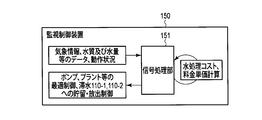
- the monitoring control device 150 is a cloud server constructed from a plurality of servers, for example.
- the monitoring control device 150 includes a water treatment facility 70, sensors 81-1 and 81-2, water storage tanks 50-1 and 50-2, a home, a sewage treatment plant 60, reservoirs 110-1 to 110-3, and a radar rain gauge. 140 and a network such as the Internet.
- the monitoring control device 150 transmits the water quality data and water volume data transmitted from the sensors 72-1 to 72-4, the water volume data transmitted from the sensors 51-1 and 51-2, and the sensors 81-1 and 81-2. Water amount data, operating conditions transmitted from the sewage treatment plant 60, usage data transmitted from the measuring devices 91-1 and 91-2, and observation data transmitted from the radar rain gauge 140 are received.
- the monitoring control device 150 includes a signal processing unit 151 as shown in FIG.
- the signal processing unit 151 includes, for example, a CPU and a storage area for programs and data for the CPU to execute processing such as a ROM and a RAM.
- the signal processing unit 151 generates first water demand data indicating the demand for clean water in the water supply area based on the usage data transmitted from the measuring device 91-1 installed in each household.
- the signal processing unit 151 generates second water demand data indicating the demand for middle water in the water supply area based on the usage data transmitted from the measuring device 91-2 installed in each home.
- the signal processing unit 151 When the hourly rate system is adopted, the signal processing unit 151 generates the first water unit price information from the water unit price for the water supply set based on the past trend or the like, and generates the generated first water unit information. Water unit price information is transmitted to the management terminal 103 installed in each household. In addition, the signal processing unit 151 generates second water unit price information from the water unit price for the middle water set based on past trends and the like, and transmits the generated second water unit price information to the management terminal 103. To do. In addition, when the real-time pricing system is adopted, the signal processing unit 151 generates first water unit price information based on the first water demand data, and the generated first water unit price information is sent to the management terminal 103. Send. The signal processing unit 151 generates second water unit price information based on the second water demand data, and transmits the generated second water unit price information to the management terminal 103.
- the signal processing unit 151 refers to the rainfall area predicted / measured by the radar rain gauge 140, the rainfall time, and the rainfall amount, and estimates the water quality and the water amount by the time zone of the rainwater at each intake point.
- the signal processing unit 151 refers to the estimation results of the water quality and the amount of rainwater at each intake point for each time zone, and controls the intake pump 111-1 so as to take in clean rainwater after a certain period of time has elapsed since the start of rainfall. To do.
- the signal processing unit 151 performs storage control on the reservoir basin 110-1 so that clean rainwater taken in the reservoir is stored in the reservoir basin 110-1.
- the signal processing unit 151 performs storage control on the reservoir 110-2 so that dirty rainwater is stored in the reservoir 110-2.
- the signal processing unit 151 includes the water amount of the water storage tanks 50-1 and 50-2 grasped from the sensors 51-1 and 51-2, the water quality and the water amount of the water source grasped from the sensors 72-1 to 72-4, and With reference to the weather information grasped by the radar rain gauge 140, the water treatment cost in the water purification plant facility 11 and the reclaimed water facility 12 is minimized while satisfying the water demand indicated by the first and second water demand data. In addition, the amount of river water, well water, rain water, and clean waste water in the water purification plant facility 11 and the reclaimed water facility 12 is determined. At this time, the amount of rainwater treated by the water purification plant facility 11 and / or the reclaimed water facility 12 is determined including clean rainwater stored in the reservoir basin 110-1.
- the signal processing unit 151 includes the intake pumps 71-1 to 71-4, the water treatment control device 13, the water storage tanks 50-1 and 50-2, the reservoir basin 110-1, and the water pump so as to realize the determined processing amount. 111-2 is controlled.
- the signal processing unit 151 refers to the operation status of the sewage treatment plant 60 transmitted from the sewage treatment plant 60, and determines whether or not the sewage treatment plant 60 has room for treating rainwater. When it is determined that there is a margin, the signal processing unit 151 performs discharge control so that the stored rainwater is discharged to the sewage treatment plant 60 with respect to the reservoir 110-2.
- the water treatment control device 13 treats clean wastewater discharged by a consumer so that it can be reused by the reclaimed water facility 12. As a result, the number of water sources from which water can be taken increases, so that water can be supplied to consumers even when the river is drought. Moreover, since the water treatment control apparatus 13 can reduce and smooth the treatment load in the water treatment plant facility 11 and the sewage treatment plant 60 as compared with the conventional one, the scale of the water treatment plant facility 11 and the sewage treatment plant 60 is increased. In addition to being able to reduce the size, it is possible to reduce the equipment cost and the operation cost of the treatment plant.
- the amount of water can be secured even during drought, and the sewage treatment cost at the sewage treatment plant can be reduced.
- the water treatment system according to the tenth embodiment includes a radar rain gauge 140 including a phased array weather radar, which has higher performance than the radar rain gauge 120 used in the water treatment system according to the eighth embodiment.
- the monitoring control device 150 controls the intake pump 111-1 so as to take in clean rain water based on the rainfall area, rainfall time and rainfall predicted / measured by the radar rain gauge 140. .
- the monitoring control device 150 can store clean rainwater more efficiently in the reservoir 110-1.
- the case where clean rainwater is stored in the reservoir basin 110-1 has been described as an example.
- the reservoir that stores clean rainwater is not limited to the reservoir basin 110-1. Absent.
- the signal processing unit 151 may control the intake pump 111-1 so that clean rainwater is stored in the nearest reservoir from the rainfall area in consideration of the distance between the rainfall area and the reservoir.
- the reservoir pond 110 stores rainwater when it rains and releases the rainwater stored after the rain. However, except for rainwater storage / release due to rainfall, rainwater does not enter or leave the aquarium 110. On the other hand, dirty wastewater is always discharged from the consumer, and the sewage treatment plant 60 processes the discharged dirty wastewater.
- FIG. 26 is a diagram showing a configuration of a water treatment system according to the eleventh embodiment.
- (c) is water amount data of the water supply line transmitted from the sensor 81-1
- (d) is water amount data of the middle water line transmitted from the sensor 81-2
- (o) is the radar data.
- the observation data transmitted from the rain gauge 120 (p) is the operation status transmitted from the sewage treatment plant 60
- (t) is the storage control and discharge control given to the reservoirs 160, 170
- ( u) is pump control given to the intake pumps 161-1 and 171-1 and the water pumps 161-2 and 171-2.
- 26 includes a water treatment facility 70, water storage tanks 50-1 and 50-2, water volume sensors 81-1 and 81-2, measuring devices 91-1 and 91-2, a management terminal 103, and a reservoir. 160, 170, a radar rain gauge 140, and a monitoring control device 180.
- the reservoir basin 160 is provided with a water intake pump 161-1 and a water supply pump 161-2.
- the intake pump 161-1 takes clean drainage water in accordance with the control from the monitoring controller 180.
- the water pump 161-2 sends clean wastewater discharged from the reservoir basin 160 to the water purification plant facility 11 and / or the reclaimed water facility 12 in accordance with the control from the monitoring control device 180.
- the retarding basin 160 stores clean waste water taken by the water intake pump 161-1 according to the storage control from the monitoring control device 180.
- the retarding basin 160 discharges the stored clean wastewater to the water purification plant facility 11 and / or the reclaimed water facility 12 in accordance with the release control from the monitoring control device 180.
- the reservoir basin 170 is provided with a water intake pump 171-1 and a water supply pump 171-2.
- the intake pump 171-1 takes in dirty waste water in accordance with the control from the monitoring control device 180.
- the water supply pump 171-2 supplies the dirty waste water discharged from the reservoir basin 170 to the sewage treatment plant 60 in accordance with the control from the monitoring control device 180.
- the reservoir basin 170 stores the dirty waste water taken by the water intake pump 171-1 according to the storage control from the monitoring controller 180.
- the retarding basin 170 discharges the stored dirty wastewater to the sewage treatment plant 60 in accordance with the release control from the monitoring control device 180.
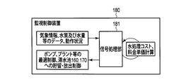
- the monitoring control device 180 is a cloud server constructed from a plurality of servers, for example.
- the monitoring control device 180 includes a water treatment facility 70, sensors 81-1, 81-2, water storage tanks 50-1, 50-2, home, sewage treatment plant 60, reservoirs 160, 170, a radar rain gauge 140, the Internet, and the like. Connected by other networks.
- the monitoring control device 180 transmits the water quality data and water volume data transmitted from the sensors 72-1 to 72-4, the water volume data transmitted from the sensors 51-1 and 51-2, and the sensors 81-1 and 81-2. Water volume data, operating conditions transmitted from the sewage treatment plant 60, usage data transmitted from the measuring devices 91-1 and 91-2, and observation data transmitted from the radar rain gauge 140 are received.
- the monitoring control device 180 includes a signal processing unit 181 as shown in FIG.
- the signal processing unit 181 includes, for example, a CPU and a storage area for programs and data for the CPU to execute processing such as a ROM and a RAM.
- the signal processing unit 181 generates first water demand data indicating the demand for clean water in the water supply area based on the usage data transmitted from the measuring device 91-1 installed in each household.
- the signal processing unit 181 generates second water demand data indicating the demand for middle water in the water supply area based on the usage data transmitted from the measuring device 91-2 installed in each household.
- the signal processing unit 181 When the hourly rate system is adopted, the signal processing unit 181 generates the first water unit price information from the water unit price for the water supply set based on the past trend or the like, and generates the generated first water unit information. Water unit price information is transmitted to the management terminal 103 installed in each household. In addition, the signal processing unit 181 generates second water unit price information from the water unit price for the middle water set based on past trends and the like, and transmits the generated second water unit price information to the management terminal 103. To do. In addition, when the real-time pricing system is adopted, the signal processing unit 181 generates first water unit price information based on the first water demand data, and the generated first water unit price information is sent to the management terminal 103. Send. In addition, the signal processing unit 181 generates second water unit price information based on the second water demand data, and transmits the generated second water unit price information to the management terminal 103.
- the signal processing unit 181 refers to the rainfall area, rainfall time, and rainfall amount predicted / measured by the radar rain gauge 140, and determines that rainwater is not stored in the reservoir 160.
- the signal processing unit 181 controls the water intake pump 161-1 so as to take in clean wastewater discharged from the home.
- the signal processing unit 181 performs storage control on the reservoir basin 160 so that the clean drainage taken is stored in the reservoir basin 160.
- the signal processing unit 181 refers to the rainfall area, rainfall time, and rainfall predicted / measured by the radar rain gauge 140, and determines that rainwater is not stored in the reservoir 170. Further, the signal processing unit 181 refers to the operation status transmitted from the sewage treatment plant 60 and determines that the processing amount in the sewage treatment plant 60 is a limit. When the signal processing unit 181 determines that rainwater is not stored in the reservoir basin 170 and the processing amount of the sewage treatment plant 60 is a limit, the signal processing unit 181 takes in the dirty wastewater discharged from the household, The intake pump 171-1 is controlled. In addition, the signal processing unit 181 performs storage control on the stagnation basin 170 so that the collected dirty wastewater is stored in the stagnation basin 170.
- the signal processing unit 181 includes the water amounts of the water storage tanks 50-1 and 50-2 grasped from the sensors 51-1 and 51-2, the water quality and the water amount of the water source grasped from the sensors 72-1 to 72-4, and With reference to the weather information grasped from the radar rain gauge 120, the water treatment cost in the water purification plant facility 11 and the reclaimed water facility 12 is minimized while satisfying the water demand indicated by the first and second water demand data. In addition, the amount of river water, well water, rain water, and clean waste water in the water purification plant facility 11 and the reclaimed water facility 12 is determined. At this time, the amount of clean wastewater treated by the water purification plant facility 11 and / or the reclaimed water facility 12 is determined including the clean wastewater stored in the reservoir basin 160. The signal processing unit 181 performs the intake pumps 71-1 to 71-4, the water treatment control device 13, the water storage tanks 50-1 and 50-2, the reservoir basin 160, and the water pump 161 so as to realize the determined processing amount. 2 is controlled.
- the signal processing unit 181 refers to the operation status of the sewage treatment plant 60 transmitted from the sewage treatment plant 60, and determines whether or not the sewage treatment plant 60 has room to treat dirty waste water. If it is determined that there is a margin, the signal processing unit 181 performs discharge control so that the stored dirty wastewater is discharged to the sewage treatment plant 60 with respect to the reservoir basin 170. In addition, the signal processing unit 181 controls the water supply pump 171-2 so that the wastewater discharged from the reservoir basin 170 is supplied to the sewage treatment plant 60.
- the water treatment control device 13 treats clean wastewater discharged by a consumer so that it can be reused by the recycled water facility 12. As a result, the number of water sources from which water can be taken increases, so that water can be supplied to consumers even when the river is drought. Moreover, since the water treatment control apparatus 13 can reduce and smooth the treatment load in the water treatment plant facility 11 and the sewage treatment plant 60 as compared with the conventional one, the scale of the water treatment plant facility 11 and the sewage treatment plant 60 is increased. In addition to being able to reduce the size, it is possible to reduce the equipment cost and the operation cost of the treatment plant.
- the amount of water can be secured even during drought, and the sewage treatment cost at the sewage treatment plant can be reduced.
- the monitoring controller 180 when rainwater is not stored in the reservoirs 160 and 170, the monitoring controller 180 stores clean wastewater and dirty wastewater in the reservoirs 160 and 170, respectively. .
- the monitoring control device 180 treats clean wastewater stored in the reservoir basin 160 as one of the water sources of the water treatment facility 70. As a result, the number of water sources capable of taking water increases, so that water can be supplied even when the river is drought.
- the monitoring and control device 180 is configured to discharge the dirty wastewater stored in the reservoir basin 170 to the sewage treatment plant 60 when the sewage treatment plant 60 has enough room. As a result, as shown in FIG. 28, it becomes possible to flatten the amount of dirty wastewater discharged from consumers as viewed from the sewage treatment plant 60. As described above, since the amount of drainage can be flattened, the size of the sewage treatment plant 60 can be reduced, or the equipment cost and the operation cost can be reduced.
- Signal Processing unit 91-1, 91-2 ... measuring device, 101, 103, 104, 105 ... management terminal, 110-1 to 110-3 ... lagging pond, 111-1 ... intake pump, 111-2 ... water pump, 120, 140 ... radar rain gauge, 160, 17 ... ponding pond, 161-1,171-1 ... water intake pump, 161-2,171-2 ... water pump, 201-1,201-2,202-1,202-2 ... valve
Abstract
A water treatment control device refers to conditions, including water shortage conditions and water treatment costs for a water treatment facility, and generates an instruction to the water treatment facility as to which type of water, among a plurality of types of water including river water from rivers, rain water, and wastewater after use by consumers, is to be taken in by the water treatment facility.
Description
本発明の実施形態は、水処理設備を制御する水処理制御装置と、水処理設備を需要家による水の需要等に基づいて制御する水処理システムに関する。
Embodiments of the present invention relate to a water treatment control device that controls a water treatment facility, and a water treatment system that controls the water treatment facility based on a demand for water by a consumer.
一般的に、水事業者は河川等の水源から水を取水し、取水した水を浄水場設備にて飲用水レベルになるように処理する。飲用水レベルに処理された水は、水道水として需要家へ供給される。需要家は、風呂、洗面所、台所、洗濯機及びトイレ等で水を使用し、使用した水を排水として排出する。排出された排水は、下水処理場にて一定の水質レベルまで処理された後、河川に放流される。
Generally, a water company takes water from a water source such as a river and treats the taken water to a drinking water level at a water purification plant facility. Water treated to the drinking water level is supplied to customers as tap water. Consumers use water in baths, washrooms, kitchens, washing machines, toilets, etc., and discharge the used water as drainage. The discharged waste water is treated to a certain water quality level at the sewage treatment plant and then discharged into the river.
ところで、水源は有限であり、渇水時には十分な水量が確保できない場合もある。また、需要家が使用した水道水は、排水として排出され、全量を下水処理場で処理することから、下水処理コストが嵩むという問題がある。
By the way, the water source is limited, and there may be a case where a sufficient amount of water cannot be secured during drought. In addition, tap water used by consumers is discharged as waste water, and the entire amount is treated at a sewage treatment plant, which raises a problem of increasing sewage treatment costs.
以上のように、従来の取水方式では、渇水時において十分な水量が確保できない場合がある。また、従来においては、需要家により排出された排水の全量を下水処理場にて処理していたため、下水処理コストが嵩むという問題がある。
As described above, the conventional water intake system may not be able to secure a sufficient amount of water during drought. Moreover, in the past, since the entire amount of waste water discharged by consumers has been treated at the sewage treatment plant, there is a problem that the cost of sewage treatment increases.
そこで、目的は、渇水時においても水量を確保可能であり、かつ、下水処理場における下水処理コストを低減可能な水処理制御装置及び水処理システムを提供することにある。
Therefore, an object is to provide a water treatment control device and a water treatment system that can secure the amount of water even during drought and can reduce the sewage treatment cost at the sewage treatment plant.
実施形態によれば、水処理制御装置は、渇水状況及び水処理設備の水処理コストを含む条件を参照し、河川からの河川水、雨水、及び、需要家による使用後の排水を含む複数種類の水のうち、前記水処理設備が取水する水の種類の指示を、前記水処理設備に対して生成する。
According to the embodiment, the water treatment control device refers to the conditions including the drought situation and the water treatment cost of the water treatment facility, and includes a plurality of types including river water from the river, rainwater, and waste water after use by consumers. An instruction of the type of water taken by the water treatment facility is generated for the water treatment facility.
以下、実施の形態について、図面を参照して説明する。
Hereinafter, embodiments will be described with reference to the drawings.
(第1の実施形態)
図1は、第1の実施形態に係る水処理設備10を含む上下水システムの構成を示す図である。図1に示す上下水システムは、水処理設備10、配水池20-1,20-2、ポンプ30-1,30-2、配水塔40-1,40-2、貯水槽50-1,50-2、下水処理場60を具備する。 (First embodiment)
FIG. 1 is a diagram illustrating a configuration of a water and sewage system including awater treatment facility 10 according to the first embodiment. 1 includes a water treatment facility 10, distribution reservoirs 20-1 and 20-2, pumps 30-1 and 30-2, distribution towers 40-1 and 40-2, and storage tanks 50-1 and 50. -It has a sewage treatment plant 60.
図1は、第1の実施形態に係る水処理設備10を含む上下水システムの構成を示す図である。図1に示す上下水システムは、水処理設備10、配水池20-1,20-2、ポンプ30-1,30-2、配水塔40-1,40-2、貯水槽50-1,50-2、下水処理場60を具備する。 (First embodiment)
FIG. 1 is a diagram illustrating a configuration of a water and sewage system including a
図2は、図1に示す水処理設備10の構成を示す図である。図2に示す水処理設備10は、浄水場設備11、再生水設備12及び水処理制御装置13を備える。
FIG. 2 is a diagram showing the configuration of the water treatment facility 10 shown in FIG. A water treatment facility 10 illustrated in FIG. 2 includes a water purification plant facility 11, a reclaimed water facility 12, and a water treatment control device 13.
浄水場設備11は、河川からの河川水、井戸水、雨水及び需要家により排出されるきれいな排水のうち、少なくともいずれかの水を、水処理制御装置13からの指示に従って取水する。なお、きれいな排水については後述する。浄水場設備11は、取水した水の水質を飲用水レベルまで浄化し、上水ラインへ送水する。以下では、上水ラインへ送水される水を上水と称する。
The water purification plant facility 11 takes at least one of the river water from the river, well water, rain water, and clean drainage discharged by the customer in accordance with an instruction from the water treatment control device 13. Clean drainage will be described later. The water purification plant equipment 11 purifies the quality of the water taken up to the level of drinking water and sends it to the water supply line. Below, the water sent to a clean water line is called clean water.
再生水設備12は、河川水、井戸水、雨水及びきれいな排水のうち、少なくともいずれかの水を、水処理制御装置13からの指示に従って取水する。再生水設備12は、取水した水の水質を、洗濯機及びトイレで使用される程度の水質に浄化し、中水ラインへ送水する。以下では、中水ラインへ送水される水を中水と称する。再生水設備12で浄化される水質レベルは、浄水場設備11で浄化される水質レベルよりも低いため、再生水設備12での処理コストは浄水場設備11での処理コストよりも低減することができる。
The reclaimed water facility 12 takes at least one of river water, well water, rainwater, and clean drainage in accordance with an instruction from the water treatment control device 13. The reclaimed water equipment 12 purifies the water quality of the taken water to a quality that can be used in a washing machine and a toilet, and sends the water to the middle water line. Below, the water sent to a middle water line is called middle water. Since the water quality level purified by the reclaimed water facility 12 is lower than the water quality level purified by the water purification plant facility 11, the treatment cost in the reclaimed water facility 12 can be reduced more than the treatment cost in the water purification plant facility 11.
水処理制御装置13は、季節及び天気等から河川水、井戸水及び雨水の渇水状況を推定し、推定した渇水状況と、貯水槽50-1,50-2での備蓄量と、河川水、井戸水、雨水及びきれいな排水の浄水場設備11及び再生水設備12での処理コストとを含む様々な条件を参照し、浄水場設備11及び再生水設備12に対し、いずれの水を取水して処理するかを指示する。例えば、浄水場設備11で、きれいな排水を飲用水レベルまで浄化するのには、処理コストが嵩むため、渇水時でない場合、きれいな排水は、再生水設備12により取水され、再生水設備12による処理された後、中水ラインへ送水されることとなる。
The water treatment control device 13 estimates the drought status of river water, well water and rain water from the season and weather, etc., the estimated drought status, the stockpiling amount in the storage tanks 50-1 and 50-2, the river water, the well water Referring to various conditions including treatment costs at the water purification plant facility 11 and the reclaimed water facility 12 for rainwater and clean wastewater, which water is to be taken and processed for the water purification plant facility 11 and the reclaimed water facility 12 Instruct. For example, in order to purify clean wastewater to the drinking water level at the water purification plant facility 11, the processing cost increases. Therefore, when it is not during drought, clean wastewater is taken in by the reclaimed water facility 12 and processed by the reclaimed water facility 12. Later, water will be sent to the middle water line.
浄水場設備11から上水ラインに送水される上水は、配水池20-1に貯められ、ポンプ30-1により配水塔40-1へ送水される。上水は、配水塔40-1から複数の需要家が存在する水供給エリアへ供給される。配水塔40-1から供給される上水の水量が多い場合、上水は貯水槽50-1に備蓄される。
Water supplied from the water purification plant facility 11 to the water supply line is stored in the distribution reservoir 20-1, and is supplied to the distribution tower 40-1 by the pump 30-1. Water is supplied from the water distribution tower 40-1 to a water supply area where a plurality of consumers are present. When the amount of clean water supplied from the distribution tower 40-1 is large, the clean water is stored in the water tank 50-1.
再生水設備12から中水ラインに送水される中水は、配水池20-2に貯められ、ポンプ30-2により配水塔40-2へ送水される。中水は、配水塔40-2から複数の需要家が存在する水供給エリアへ供給される。配水塔40-2から供給される中水の水量が多い場合、中水は貯水槽50-2に備蓄される。
The middle water sent from the reclaimed water facility 12 to the middle water line is stored in the distribution reservoir 20-2 and sent to the distribution tower 40-2 by the pump 30-2. The middle water is supplied from the water distribution tower 40-2 to a water supply area where there are a plurality of consumers. When the amount of middle water supplied from the water distribution tower 40-2 is large, the middle water is stored in the water storage tank 50-2.
水供給エリアに存在する各需要家が生活する家庭には、図2で示すように、風呂、洗面所、台所、洗濯機及びトイレ等、水を使用する複数の設備が設けられている。家庭に設けられる複数の設備は、設備毎に使用する水の水質が異なる。例えば、風呂、洗面所及び台所は、飲用水レベルの水質が求められ、洗濯機及びトイレでは、そこまでの水質は求められない。そこで、風呂、洗面所及び台所は、上水が供給されるようになっており、洗濯機及びトイレは、中水が供給されるようになっている。
As shown in FIG. 2, a plurality of facilities using water, such as a bath, a washroom, a kitchen, a washing machine, and a toilet, are provided in the home where each consumer in the water supply area lives. A plurality of facilities provided in a home have different water quality for each facility. For example, baths, washrooms, and kitchens are required to have drinking water level water quality, and washing machines and toilets do not require water quality up to that level. Therefore, clean water is supplied to baths, washrooms, and kitchens, and medium water is supplied to washing machines and toilets.
また、家庭では、使用後の排水を、排水の水質レベルに応じて分別する。例えば、風呂、洗面所及び台所で使用された水は、きれいな排水であり、水処理設備10へ送水される。一方、洗濯機及びトイレで使用された水は、汚い排水であり、下水処理場60へ排出される。下水処理場60は、水供給エリアから排出される汚い排水を、一定の水質レベルまで処理した後、河川等へ放流する。なお、渇水状態が深刻な場合には、洗濯機及びトイレで使用された水であっても、中水として利用可能な水質レベルであれば、水処理設備10へ送水することも考えられる。
Also, at home, wastewater after use is separated according to the water quality level of the wastewater. For example, water used in a bath, a washroom, and a kitchen is clean wastewater and is sent to the water treatment facility 10. On the other hand, the water used in the washing machine and toilet is dirty wastewater and is discharged to the sewage treatment plant 60. The sewage treatment plant 60 treats dirty wastewater discharged from the water supply area to a certain water quality level, and then discharges it to a river or the like. If the drought condition is serious, water used in the washing machine and toilet may be sent to the water treatment facility 10 as long as the water quality level is available as intermediate water.
以上のように、第1の実施形態に係る水処理制御装置13は、需要家により排出されるきれいな排水を再生水設備12により、再利用可能なように処理するようにしている。これにより、水を取水可能な水源が増えることになるため、河川の渇水時等においても水を需要家へ供給することが可能となる。また、水処理制御装置13は、浄水場設備11及び下水処理場60での処理負荷を従来よりも低減させることが可能となるため、浄水場設備11及び下水処理場60の規模を従来よりも縮小することが可能となると共に、設備コストの低減、及び、処理場の運用コストの低減を図ることが可能となる。また、河川からの取水量が減ることで、水事業者が支払ってきた取水権のコストを低減することも可能となる。
As described above, the water treatment control device 13 according to the first embodiment treats clean wastewater discharged by a consumer so that it can be reused by the reclaimed water facility 12. As a result, the number of water sources from which water can be taken increases, so that water can be supplied to consumers even when the river is drought. Moreover, since it becomes possible for the water treatment control apparatus 13 to reduce the processing load in the water purification plant equipment 11 and the sewage treatment plant 60 more than before, the scale of the water treatment plant equipment 11 and the sewage treatment plant 60 is made larger than before. It is possible to reduce the facility cost, and it is possible to reduce the facility cost and the operation cost of the treatment plant. In addition, by reducing the amount of water taken from the river, it is possible to reduce the cost of water intake rights paid by the water company.
したがって、第1の実施形態に係る水処理制御装置13によれば、渇水時においても水量を確保でき、かつ、下水処理場における下水処理コストを低減することができる。
Therefore, according to the water treatment control device 13 according to the first embodiment, the amount of water can be secured even during drought and the sewage treatment cost at the sewage treatment plant can be reduced.
(第2の実施形態)
図3は、第2の実施形態に係る水処理システムの構成を示す図である。図3における(a)はセンサ72-1~72-4から送信される水質データ(及び水量データ)であり、(b)はセンサ51-1,51-2から送信される水量データであり、(c)はセンサ81-1から送信される上水ラインの水量データであり、(d)はセンサ81-2から送信される中水ラインの水量データであり、(e)は取水ポンプ71-1~71-4へ与えられるポンプ制御であり、(f)は水処理設備70へ与えられる水処理の制御であり、(g)は貯水槽50-1,50-2へ与えられる貯水制御及び放水制御である。図3に示す水処理システムは、水処理設備70、貯水槽50-1,50-2、水量センサ81-1,81-2及び監視制御装置80を備える。 (Second Embodiment)
FIG. 3 is a diagram illustrating a configuration of a water treatment system according to the second embodiment. 3A is water quality data (and water volume data) transmitted from the sensors 72-1 to 72-4, and FIG. 3B is water volume data transmitted from the sensors 51-1 and 51-2. (C) is water amount data of the water supply line transmitted from the sensor 81-1, (d) is water amount data of the middle water line transmitted from the sensor 81-2, and (e) is an intake pump 71- (F) is a control of water treatment given to thewater treatment facility 70, and (g) is a storage control given to the water storage tanks 50-1 and 50-2. Water discharge control. The water treatment system shown in FIG. 3 includes a water treatment facility 70, water storage tanks 50-1 and 50-2, water volume sensors 81-1 and 81-2, and a monitoring control device 80.
図3は、第2の実施形態に係る水処理システムの構成を示す図である。図3における(a)はセンサ72-1~72-4から送信される水質データ(及び水量データ)であり、(b)はセンサ51-1,51-2から送信される水量データであり、(c)はセンサ81-1から送信される上水ラインの水量データであり、(d)はセンサ81-2から送信される中水ラインの水量データであり、(e)は取水ポンプ71-1~71-4へ与えられるポンプ制御であり、(f)は水処理設備70へ与えられる水処理の制御であり、(g)は貯水槽50-1,50-2へ与えられる貯水制御及び放水制御である。図3に示す水処理システムは、水処理設備70、貯水槽50-1,50-2、水量センサ81-1,81-2及び監視制御装置80を備える。 (Second Embodiment)
FIG. 3 is a diagram illustrating a configuration of a water treatment system according to the second embodiment. 3A is water quality data (and water volume data) transmitted from the sensors 72-1 to 72-4, and FIG. 3B is water volume data transmitted from the sensors 51-1 and 51-2. (C) is water amount data of the water supply line transmitted from the sensor 81-1, (d) is water amount data of the middle water line transmitted from the sensor 81-2, and (e) is an intake pump 71- (F) is a control of water treatment given to the
水処理設備70は、浄水場設備11、再生水設備12、水処理制御装置13、取水ポンプ71-1~71-4及びセンサ72-1~72-4を備える。
The water treatment facility 70 includes a water purification plant facility 11, a reclaimed water facility 12, a water treatment control device 13, water intake pumps 71-1 to 71-4, and sensors 72-1 to 72-4.
センサ72-1は、河川水の水質を計測し、取得した水質データを監視制御装置80へ送信する。取水ポンプ71-1は、監視制御装置80からの制御に従い、河川水を取水し、取水した河川水を浄水場設備11及び/又は再生水設備12へ送水する。
The sensor 72-1 measures the water quality of the river water and transmits the acquired water quality data to the monitoring control device 80. The intake pump 71-1 takes river water in accordance with the control from the monitoring control device 80, and supplies the taken river water to the water purification plant facility 11 and / or the reclaimed water facility 12.
センサ72-2は、井戸水の水質及び水量を計測し、取得した水質データ及び水量データを監視制御装置80へ送信する。取水ポンプ71-2は、監視制御装置80からの制御に従い、井戸水を取水し、取水した井戸水を浄水場設備11及び/又は再生水設備12へ送水する。
The sensor 72-2 measures the water quality and amount of well water, and transmits the acquired water quality data and water amount data to the monitoring control device 80. The intake pump 71-2 takes well water in accordance with the control from the monitoring control device 80, and supplies the taken well water to the water purification plant facility 11 and / or the reclaimed water facility 12.
センサ72-3は、雨水の水質を計測し、取得した水質データを監視制御装置80へ送信する。取水ポンプ71-3は、監視制御装置80からの制御に従い、雨水を取水し、取水した雨水を浄水場設備11及び/又は再生水設備12へ送水する。
The sensor 72-3 measures the quality of rainwater and transmits the acquired water quality data to the monitoring control device 80. The water intake pump 71-3 takes rainwater in accordance with the control from the monitoring control device 80, and supplies the taken rainwater to the water purification plant facility 11 and / or the reclaimed water facility 12.
センサ72-4は、きれいな排水の水質及び水量を計測し、取得した水質データ及び水量データを監視制御装置80へ送信する。取水ポンプ71-4は、監視制御装置80からの制御に従い、きれいな排水を取水し、取水したきれいな排水を浄水場設備11及び/又は再生水設備12へ送水する。
Sensor 72-4 measures the quality and quantity of clean wastewater, and transmits the acquired water quality data and quantity data to the monitoring control device 80. The water intake pump 71-4 takes clean wastewater according to the control from the monitoring control device 80, and supplies the clean water that has been taken up to the water purification plant facility 11 and / or the reclaimed water facility 12.
貯水槽50-1には、センサ51-1が備えられる。センサ51-1は、貯水槽50-1の水量を計測し、取得した水量データを監視制御装置80へ送信する。貯水槽50-1は、監視制御装置80からの貯水制御に従い、上水を貯水する。また、貯水槽50-1は、監視制御装置80からの放水制御に従い、備蓄する上水を上水ラインへ放水する。
The water storage tank 50-1 is provided with a sensor 51-1. The sensor 51-1 measures the amount of water in the water tank 50-1, and transmits the acquired water amount data to the monitoring control device 80. The water storage tank 50-1 stores water according to the water storage control from the monitoring control device 80. In addition, the water storage tank 50-1 discharges the stored water to the water supply line in accordance with the water discharge control from the monitoring control device 80.
貯水槽50-2には、センサ51-2が備えられる。センサ51-2は、貯水槽50-2の水量を計測し、取得した水量データを監視制御装置80へ送信する。貯水槽50-2は、監視制御装置80からの貯水制御に従い、中水を貯水する。また、貯水槽50-2は、監視制御装置80からの放水制御に従い、備蓄する中水を中水ラインへ放水する。
The water storage tank 50-2 is provided with a sensor 51-2. The sensor 51-2 measures the amount of water in the water storage tank 50-2 and transmits the acquired water amount data to the monitoring control device 80. The water storage tank 50-2 stores middle water in accordance with the water storage control from the monitoring control device 80. Further, the water storage tank 50-2 discharges the stored intermediate water to the intermediate water line in accordance with the discharge control from the monitoring control device 80.
センサ81-1は、上水ラインに設けられ、水供給エリアに供給される上水の水量を計測する。センサ81-1は、取得した水量データを監視制御装置80へ送信する。
Sensor 81-1 is provided in the water supply line, and measures the amount of water supplied to the water supply area. The sensor 81-1 transmits the acquired water amount data to the monitoring control device 80.
センサ81-2は、中水ラインに設けられ、水供給エリアに供給される中水の水量を計測する。センサ81-2は、取得した水量データを監視制御装置80へ送信する。
The sensor 81-2 is provided in the middle water line and measures the amount of middle water supplied to the water supply area. The sensor 81-2 transmits the acquired water amount data to the monitoring control device 80.
監視制御装置80は、例えば、複数のサーバから構築されるクラウドサーバである。監視制御装置80は、水処理設備70、センサ81-1,81-2及び貯水槽50-1,50-2とインターネット等のネットワークにより接続される。監視制御装置80は、センサ72-1~72-4から送信される水質データ及び水量データ、センサ51-1,51-2から送信される水量データ、並びに、センサ81-1,81-2から送信される水量データを受信する。
The monitoring control device 80 is, for example, a cloud server constructed from a plurality of servers. The monitoring control device 80 is connected to the water treatment facility 70, the sensors 81-1 and 81-2, and the water storage tanks 50-1 and 50-2 through a network such as the Internet. The monitoring and control device 80 includes water quality data and water volume data transmitted from the sensors 72-1 to 72-4, water volume data transmitted from the sensors 51-1 and 51-2, and sensors 81-1 and 81-2. Receive the transmitted water volume data.
監視制御装置80は、図4に示すように、信号処理部82を備える。信号処理部82は、例えば、CPU(Central Processing Unit)、並びに、ROM(Read Only Memory)及びRAM(Random Access Memory)等のCPUが処理を実行するためのプログラムやデータの格納領域等を含む。信号処理部82は、センサ81-1,81-2から送信される水量データに基づき、水供給エリアにおける上水の水需要を示す第1の水需要データと、水供給エリアにおける中水の水需要を示す第2の水需要データとを生成する。信号処理部82は、センサ51-1,51-2から把握される貯水槽50-1,50-2の水量、並びに、センサ72-1~72-4から把握される水源の水質及び水量を参照し、第1及び第2の水需要データにより示される水需要を満たしつつ、浄水場設備11及び再生水設備12における水処理コストが最小限となるように、浄水場設備11及び再生水設備12における河川水、井戸水、雨水及びきれいな排水の処理量を決定する。信号処理部82は、決定した処理量を実現するように、取水ポンプ71-1~71-4、水処理制御装置13及び貯水槽50-1,50-2を制御する。
The monitoring control device 80 includes a signal processing unit 82 as shown in FIG. The signal processing unit 82 includes, for example, a CPU (Central Processing Unit), and a storage area for programs and data for the CPU to execute processing such as ROM (Read Only Memory) and RAM (Random Access Memory). The signal processing unit 82, based on the water amount data transmitted from the sensors 81-1 and 81-2, first water demand data indicating the demand for clean water in the water supply area, and water in the middle water in the water supply area. Second water demand data indicating the demand is generated. The signal processing unit 82 determines the water amount of the water storage tanks 50-1 and 50-2 grasped from the sensors 51-1 and 51-2, and the water quality and the water amount of the water source grasped from the sensors 72-1 to 72-4. With reference to the water purification plant facility 11 and the reclaimed water facility 12, the water treatment cost in the water purification plant facility 11 and the reclaimed water facility 12 is minimized while satisfying the water demand indicated by the first and second water demand data. Determine the volume of river water, well water, rainwater and clean wastewater. The signal processing unit 82 controls the water intake pumps 71-1 to 71-4, the water treatment control device 13, and the water storage tanks 50-1 and 50-2 so as to realize the determined processing amount.
河川水、井戸水及び雨水等の水源は水量及び/又は水質が常に変化する。例えば、雨季にはたくさんの雨水が確保できるが、乾季には雨水の確保が難しくなる。また、雨が降って間もない時間帯の雨水は塵や埃等による汚れがひどいが、一定時間が経過すると雨水の汚れは改善する。汚れがひどい水に対して水処理を行うよりも、汚れが少ない水に対して水処理を行う方が、水処理コストを少なく抑えられる。このように、水源の水量及び水質に基づいて水の処理量を決定することは効果的である。
Water sources such as river water, well water, and rainwater constantly change in water volume and / or quality. For example, a lot of rainwater can be secured in the rainy season, but it becomes difficult to secure rainwater in the dry season. In addition, the rainwater in the time zone just after the rain is severely contaminated with dust, dust, etc., but the rainwater dirt improves after a certain period of time. Water treatment costs can be reduced by performing water treatment on water with less dirt than performing water treatment on water with severe dirt. Thus, it is effective to determine the amount of water to be treated based on the amount and quality of the water source.
なお、浄水場設備11において、水処理コストを低減させる制御としては、例えば、水質が所定レベルよりも高い場合には、浄水場設備11に設けられる好気槽におけるブロアの量を減らす制御が挙げられる。
In addition, as control which reduces water treatment cost in the water purification plant equipment 11, when water quality is higher than a predetermined level, control which reduces the quantity of the blower in the aerobic tank provided in the water purification plant equipment 11 is mentioned, for example. It is done.
以上のように、第2の実施形態に係る水処理制御装置13は、需要家により排出されるきれいな排水を再生水設備12により、再利用可能なように処理するようにしている。これにより、水を取水可能な水源が増えることになるため、河川の渇水時等においても水を需要家へ供給することが可能となる。また、水処理制御装置13は、浄水場設備11及び下水処理場60での処理負荷を従来よりも低減させることが可能となるため、浄水場設備11及び下水処理場60の規模を従来よりも縮小することが可能となると共に、設備コストの低減、及び、処理場の運用コストの低減を図ることが可能となる。
As described above, the water treatment control device 13 according to the second embodiment treats clean wastewater discharged by a consumer so that it can be reused by the reclaimed water facility 12. As a result, the number of water sources from which water can be taken increases, so that water can be supplied to consumers even when the river is drought. Moreover, since it becomes possible for the water treatment control apparatus 13 to reduce the processing load in the water purification plant equipment 11 and the sewage treatment plant 60 more than before, the scale of the water treatment plant equipment 11 and the sewage treatment plant 60 is made larger than before. It is possible to reduce the facility cost, and it is possible to reduce the facility cost and the operation cost of the treatment plant.
したがって、第2の実施形態に係る水処理システムによれば、渇水時においても水量を確保でき、かつ、下水処理場における下水処理コストを低減することができる。
Therefore, according to the water treatment system according to the second embodiment, the amount of water can be secured even during drought, and the sewage treatment cost at the sewage treatment plant can be reduced.
また、第2の実施形態に係る水処理システムは、センサ72-1~72-4により取得される水源についての水質データ及び水量データ、センサ51-1,51-2により取得される貯水槽50-1,50-2の水量データ、並びに、センサ81-1,81-2により取得される水供給エリアでの水量データに基づいて、水処理設備70を制御するようにしている。これにより、浄水場設備11及び再生水設備12における処理コストをより効率的に低減させることが可能となる。
Further, the water treatment system according to the second embodiment includes water quality data and water volume data on water sources acquired by the sensors 72-1 to 72-4, and the water tank 50 acquired by the sensors 51-1 and 51-2. The water treatment facility 70 is controlled based on the water amount data of -1,50-2 and the water amount data in the water supply area acquired by the sensors 81-1, 81-2. Thereby, the processing cost in the water purification plant equipment 11 and the reclaimed water equipment 12 can be more efficiently reduced.
(第3の実施形態)
図5は、第3の実施形態に係る水処理システムの構成を示す図である。図5における(a)はセンサ72-1~72-4から送信される水質データ(及び水量データ)であり、(b)はセンサ51-1,51-2から送信される水量データであり、(c)はセンサ81-1から送信される上水ラインの水量データであり、(d)はセンサ81-2から送信される中水ラインの水量データであり、(e)は取水ポンプ71-1~71-4へ与えられるポンプ制御であり、(f)は水処理設備70へ与えられる水処理の制御であり、(g)は貯水槽50-1,50-2へ与えられる貯水制御及び放水制御であり、(h)は計測装置91-1からアップロードされる上水の使用量データであり、(i)は計測装置91-2からアップロードされる中水の使用量データである。図5に示す水処理システムは、水処理設備70、貯水槽50-1,50-2、水量センサ81-1,81-2、計測装置91-1,91-2及び監視制御装置90を備える。 (Third embodiment)
FIG. 5 is a diagram illustrating a configuration of a water treatment system according to the third embodiment. In FIG. 5, (a) is water quality data (and water amount data) transmitted from the sensors 72-1 to 72-4, and (b) is water amount data transmitted from the sensors 51-1 and 51-2. (C) is water amount data of the water supply line transmitted from the sensor 81-1, (d) is water amount data of the middle water line transmitted from the sensor 81-2, and (e) is an intake pump 71- (F) is a control of water treatment given to thewater treatment facility 70, and (g) is a storage control given to the water storage tanks 50-1 and 50-2. Water discharge control, (h) is water usage data uploaded from the measuring device 91-1, and (i) is medium water usage data uploaded from the measuring device 91-2. The water treatment system shown in FIG. 5 includes a water treatment facility 70, water storage tanks 50-1 and 50-2, water volume sensors 81-1 and 81-2, measuring devices 91-1 and 91-2, and a monitoring control device 90. .
図5は、第3の実施形態に係る水処理システムの構成を示す図である。図5における(a)はセンサ72-1~72-4から送信される水質データ(及び水量データ)であり、(b)はセンサ51-1,51-2から送信される水量データであり、(c)はセンサ81-1から送信される上水ラインの水量データであり、(d)はセンサ81-2から送信される中水ラインの水量データであり、(e)は取水ポンプ71-1~71-4へ与えられるポンプ制御であり、(f)は水処理設備70へ与えられる水処理の制御であり、(g)は貯水槽50-1,50-2へ与えられる貯水制御及び放水制御であり、(h)は計測装置91-1からアップロードされる上水の使用量データであり、(i)は計測装置91-2からアップロードされる中水の使用量データである。図5に示す水処理システムは、水処理設備70、貯水槽50-1,50-2、水量センサ81-1,81-2、計測装置91-1,91-2及び監視制御装置90を備える。 (Third embodiment)
FIG. 5 is a diagram illustrating a configuration of a water treatment system according to the third embodiment. In FIG. 5, (a) is water quality data (and water amount data) transmitted from the sensors 72-1 to 72-4, and (b) is water amount data transmitted from the sensors 51-1 and 51-2. (C) is water amount data of the water supply line transmitted from the sensor 81-1, (d) is water amount data of the middle water line transmitted from the sensor 81-2, and (e) is an intake pump 71- (F) is a control of water treatment given to the
計測装置91-1は、例えば、スマートメータであり、水供給エリアに存在する各家庭における上水ラインに設置される。計測装置91-1は、需要家による水の使用量のうち、上水の使用量を計測する。計測装置91-1は、計測した使用量を使用量データとして監視制御装置90へリアルタイムでアップロードする。
The measuring device 91-1 is, for example, a smart meter, and is installed in a water supply line in each household existing in the water supply area. The measuring device 91-1 measures the amount of clean water out of the amount of water used by consumers. The measuring device 91-1 uploads the measured usage amount as usage amount data to the monitoring control device 90 in real time.
計測装置91-2は、例えば、スマートメータであり、水供給エリアに存在する各家庭における中水ラインに設置される。計測装置91-2は、需要家による水の使用量のうち、中水の使用量を計測する。計測装置91-2は、計測した使用量を使用量データとして監視制御装置90へリアルタイムでアップロードする。
The measuring device 91-2 is, for example, a smart meter, and is installed in the middle water line in each household existing in the water supply area. The measuring device 91-2 measures the amount of medium water out of the amount of water used by consumers. The measuring device 91-2 uploads the measured usage amount as usage amount data to the monitoring control device 90 in real time.
監視制御装置90は、例えば、複数のサーバから構築されるクラウドサーバである。監視制御装置90は、水処理設備70、センサ81-1,81-2、貯水槽50-1,50-2及び家庭とインターネット等のネットワークにより接続される。監視制御装置90は、センサ72-1~72-4から送信される水質データ及び水量データ、センサ51-1,51-2から送信される水量データ、センサ81-1,81-2から送信される水量データ、並びに、計測装置91-1,91-2から送信される使用量データを受信する。
The monitoring control device 90 is, for example, a cloud server constructed from a plurality of servers. The monitoring control device 90 is connected to the water treatment facility 70, the sensors 81-1 and 81-2, the water storage tanks 50-1 and 50-2, and the home via a network such as the Internet. The monitoring control device 90 transmits the water quality data and water volume data transmitted from the sensors 72-1 to 72-4, the water volume data transmitted from the sensors 51-1 and 51-2, and the sensors 81-1 and 81-2. Water amount data and usage amount data transmitted from the measuring devices 91-1 and 91-2 are received.
監視制御装置90は、図6に示すように、信号処理部92を備える。信号処理部92は、例えば、CPU、並びに、ROM及びRAM等のCPUが処理を実行するためのプログラムやデータの格納領域等を含む。信号処理部92は、各家庭に設置される計測装置91-1から送信される使用量データに基づき、水供給エリアにおける上水の水需要を示す第1の水需要データを生成する。また、信号処理部92は、各家庭に設置される計測装置91-2から送信される使用量データに基づき、水供給エリアにおける中水の水需要を示す第2の水需要データを生成する。また、第1の水需要データおよび第2の水需要データを生成する際に、センサ81-1から送信される水量データ及びセンサ81-2から送信される水量データを用いて補完することもできる。例えば、計測装置の未整備や故障などにより全需要家の計測装置から使用量データが得られない場合は、センサから送信される水量データの方が大きな値となる。このようなときには、計測装置の使用量データとセンサの水量データを用いて、水需要データを生成する。例えば、過去の使用量データと水量データとの関係を参照して、水需要量データを生成することが可能である。
The monitoring control device 90 includes a signal processing unit 92 as shown in FIG. The signal processing unit 92 includes, for example, a CPU and a storage area for programs and data for the CPU to execute processing such as ROM and RAM. The signal processing unit 92 generates first water demand data indicating the demand for clean water in the water supply area based on the usage data transmitted from the measuring device 91-1 installed in each household. In addition, the signal processing unit 92 generates second water demand data indicating the demand for middle water in the water supply area based on the usage data transmitted from the measuring device 91-2 installed in each household. Further, when the first water demand data and the second water demand data are generated, it is possible to supplement the water amount data transmitted from the sensor 81-1 and the water amount data transmitted from the sensor 81-2. . For example, when the usage data cannot be obtained from the measuring devices of all consumers due to the undeveloped or malfunctioning measuring device, the water amount data transmitted from the sensor has a larger value. In such a case, the water demand data is generated using the usage amount data of the measuring device and the water amount data of the sensor. For example, it is possible to generate water demand data by referring to the relationship between past usage data and water data.
信号処理部92は、センサ51-1,51-2から把握される貯水槽50-1,50-2の水量、並びに、センサ72-1~72-4から把握される水源の水質及び水量を参照し、第1及び第2の水需要データにより示される水需要を満たしつつ、浄水場設備11及び再生水設備12における水処理コストが最小限となるように、浄水場設備11及び再生水設備12における河川水、井戸水、雨水及びきれいな排水の処理量を決定する。信号処理部92は、決定した処理量を実現するように、取水ポンプ71-1~71-4、水処理制御装置13及び貯水槽50-1,50-2を制御する。
The signal processing unit 92 determines the water amount of the water storage tanks 50-1 and 50-2 grasped from the sensors 51-1 and 51-2, and the water quality and the water amount of the water source grasped from the sensors 72-1 to 72-4. With reference to the water purification plant facility 11 and the reclaimed water facility 12, the water treatment cost in the water purification plant facility 11 and the reclaimed water facility 12 is minimized while satisfying the water demand indicated by the first and second water demand data. Determine the volume of river water, well water, rainwater and clean wastewater. The signal processing unit 92 controls the water intake pumps 71-1 to 71-4, the water treatment control device 13, and the water storage tanks 50-1 and 50-2 so as to realize the determined processing amount.
以上のように、第3の実施形態に係る水処理制御装置13は、需要家により排出されるきれいな排水を再生水設備12により、再利用可能なように処理するようにしている。これにより、水を取水可能な水源が増えることになるため、河川の渇水時等においても水を需要家へ供給することが可能となる。また、水処理制御装置13は、浄水場設備11及び下水処理場60での処理負荷を従来よりも低減させることが可能となるため、浄水場設備11及び下水処理場60の規模を従来よりも縮小することが可能となると共に、設備コストの低減、及び、処理場の運用コストの低減を図ることが可能となる。
As described above, the water treatment control device 13 according to the third embodiment treats clean wastewater discharged by a consumer so that it can be reused by the reclaimed water facility 12. As a result, the number of water sources from which water can be taken increases, so that water can be supplied to consumers even when the river is drought. Moreover, since it becomes possible for the water treatment control apparatus 13 to reduce the processing load in the water purification plant equipment 11 and the sewage treatment plant 60 more than before, the scale of the water treatment plant equipment 11 and the sewage treatment plant 60 is made larger than before. It is possible to reduce the facility cost, and it is possible to reduce the facility cost and the operation cost of the treatment plant.
したがって、第3の実施形態に係る水処理システムによれば、渇水時においても水量を確保でき、かつ、下水処理場における下水処理コストを低減することができる。
Therefore, according to the water treatment system according to the third embodiment, the amount of water can be secured even during drought, and the sewage treatment cost at the sewage treatment plant can be reduced.
また、第3の実施形態に係る水処理システムは、センサ72-1~72-4により取得される水源についての水質データ及び水量データ、センサ51-1,51-2により取得される貯水槽50-1,50-2の水量データ、並びに、計測装置91-1,91-2により取得される各家庭における水の使用量データに基づいて、水処理設備70を制御するようにしている。これにより、監視制御装置90は、各需要家の水質別水需要量をリアルタイムで把握することが可能となるため、時々刻々と変化する水供給エリアでの水需要に即して、水処理設備70及び貯水槽50-1,50-2を最適に運用することが可能となる。
In addition, the water treatment system according to the third embodiment includes water quality data and water volume data on water sources acquired by the sensors 72-1 to 72-4, and the water tank 50 acquired by the sensors 51-1 and 51-2. The water treatment facility 70 is controlled based on the water amount data of -1,50-2 and the water usage data in each home acquired by the measuring devices 91-1, 91-2. As a result, the monitoring and control device 90 can grasp the water demand by water quality of each consumer in real time, so that the water treatment facility is adapted to the water demand in the water supply area that changes from moment to moment. 70 and the water storage tanks 50-1 and 50-2 can be optimally operated.
(第4の実施形態)
第1乃至第3の実施形態では、水の基本使用量をベースとし、水の使用量に応じた従量課金制を採る一般的な水道料金制度を採用する場合を例に説明した。しかしながら、供給する水は水源によって取水権コスト及び/又は水処理コスト(水質によってコストが異なる)等により水供給コストが異なる。また、渇水時には水の安定供給のために河川からの取水量をできるだけ抑えたいという思いが働く。そこで、第4乃至第11の実施形態では、水供給コストの差、及び、意図的な運用方針を需要家向け水単価に反映させる制度、例えば、時間帯別料金制度又はリアルタイムプライシング制度を採用する場合について説明する。時間帯別料金制度とは、過去のトレンド等に基づき、時間帯及び期間(季節等)によって水単価を変化させる料金制度であり、水単価の推移は、例えば、図7のように示される。リアルタイムプライシング制度とは、実際の状況にあわせて料金体系を変更する料金制度であり、水単価の推移は、例えば、図8のように示される。 (Fourth embodiment)
In the first to third embodiments, an example has been described in which a general water rate system that employs a pay-per-use system according to the amount of water used is based on the basic amount of water used. However, the water supply cost differs depending on the water source due to the water intake cost and / or the water treatment cost (the cost varies depending on the water quality). In addition, the desire to keep the water intake from the river as much as possible in order to ensure a stable supply of water during drought. Therefore, in the fourth to eleventh embodiments, a system that reflects the difference in water supply costs and the intentional operation policy in the unit water price for consumers, for example, a time-based rate system or a real-time pricing system is adopted. The case will be described. The hourly rate system is a rate system that changes the unit price of water according to the time period and period (season etc.) based on past trends and the like, and the transition of the unit price of water is shown in FIG. The real-time pricing system is a charge system that changes the charge system according to the actual situation, and the transition of the water unit price is shown in FIG.
図9は、第4の実施形態に係る水処理システムの構成を示す図である。図9における(a)はセンサ72-1~72-4から送信される水質データ(及び水量データ)であり、(b)はセンサ51-1,51-2から送信される水量データであり、(c)はセンサ81-1から送信される上水ラインの水量データであり、(d)はセンサ81-2から送信される中水ラインの水量データであり、(e)は取水ポンプ71-1~71-4へ与えられるポンプ制御であり、(f)は水処理設備70へ与えられる水処理の制御であり、(g)は貯水槽50-1,50-2へ与えられる貯水制御及び放水制御であり、(h)は計測装置91-1からアップロードされる上水の使用量データであり、(i)は計測装置91-2からアップロードされる中水の使用量データであり、(j)は管理端末101へ与えられる第1及び第2の水単価情報である。図9に示す水処理システムは、水処理設備70、貯水槽50-1,50-2、水量センサ81-1,81-2、計測装置91-1,91-2、管理端末101及び監視制御装置100を備える。
FIG. 9 is a diagram showing a configuration of a water treatment system according to the fourth embodiment. In FIG. 9, (a) is water quality data (and water amount data) transmitted from the sensors 72-1 to 72-4, and (b) is water amount data transmitted from the sensors 51-1 and 51-2. (C) is water amount data of the water supply line transmitted from the sensor 81-1, (d) is water amount data of the middle water line transmitted from the sensor 81-2, and (e) is an intake pump 71- (F) is a control of water treatment given to the water treatment facility 70, and (g) is a storage control given to the water storage tanks 50-1 and 50-2. (H) is water usage data uploaded from the measuring device 91-1, (i) is middle water usage data uploaded from the measuring device 91-2, j) is the first number given to the management terminal 101. A second water unit price information. The water treatment system shown in FIG. 9 includes a water treatment facility 70, water storage tanks 50-1 and 50-2, water volume sensors 81-1 and 81-2, measuring devices 91-1 and 91-2, a management terminal 101, and monitoring control. A device 100 is provided.
管理端末101は、例えば、表示部付きの家庭向けエネルギー管理システム(HEMS:Home Energy Management System)であり、水供給エリアに存在する各家庭に設置される。管理端末101は、監視制御装置100から与えられる第1及び第2の水単価情報を表示する。第1の水単価情報は、上水の水単価を表し、第2の水単価情報は、中水の水単価を表す。需要家は、管理端末101に表示される第1及び第2の水単価情報を参照して家庭に備えられる設備を使用する。例えば、需要家は、上水の水単価が現時間帯において高いと判断した場合、風呂、洗面所及び台所の使用を控え、上水の水単価が現時間帯において安いと判断した場合、これらの設備を使用する。
The management terminal 101 is, for example, a home energy management system (HEMS) with a display unit, and is installed in each home existing in the water supply area. The management terminal 101 displays the first and second water unit price information given from the monitoring control device 100. 1st water unit price information represents the water unit price of clean water, and 2nd water unit price information represents the water unit price of middle water. A consumer uses the equipment with which a household is equipped with reference to the 1st and 2nd water unit price information displayed on the management terminal 101. FIG. For example, if a consumer determines that the unit price of clean water is high at the current time, he / she refrains from using a bath, a washroom, and the kitchen, and if the unit price of clean water is low at the current time, Use the equipment.
監視制御装置100は、例えば、複数のサーバから構築されるクラウドサーバである。監視制御装置100は、水処理設備70、センサ81-1,81-2、貯水槽50-1,50-2及び家庭とインターネット等のネットワークにより接続される。監視制御装置100は、センサ72-1~72-4から送信される水質データ及び水量データ、センサ51-1,51-2から送信される水量データ、センサ81-1,81-2から送信される水量データ、並びに、計測装置91-1,91-2から送信される使用量データを受信する。
The monitoring control device 100 is a cloud server constructed from a plurality of servers, for example. The monitoring control device 100 is connected to the water treatment facility 70, the sensors 81-1 and 81-2, the water storage tanks 50-1 and 50-2, and the home via a network such as the Internet. The monitoring and control apparatus 100 transmits water quality data and water amount data transmitted from the sensors 72-1 to 72-4, water amount data transmitted from the sensors 51-1 and 51-2, and transmitted from the sensors 81-1 and 81-2. Water amount data and usage amount data transmitted from the measuring devices 91-1 and 91-2 are received.
監視制御装置100は、図10に示すように、信号処理部102を備える。信号処理部102は、例えば、CPU、並びに、ROM及びRAM等のCPUが処理を実行するためのプログラムやデータの格納領域等を含む。信号処理部102は、各家庭に設置される計測装置91-1から送信される使用量データに基づき、水供給エリアにおける上水の水需要を示す第1の水需要データを生成する。また、信号処理部102は、各家庭に設置される計測装置91-2から送信される使用量データに基づき、水供給エリアにおける中水の水需要を示す第2の水需要データを生成する。
The monitoring control device 100 includes a signal processing unit 102 as shown in FIG. The signal processing unit 102 includes, for example, a CPU and a storage area for programs and data for the CPU to execute processing such as ROM and RAM. The signal processing unit 102 generates first water demand data indicating the demand for clean water in the water supply area based on the usage data transmitted from the measuring device 91-1 installed in each household. Further, the signal processing unit 102 generates second water demand data indicating the demand for middle water in the water supply area based on the usage data transmitted from the measuring device 91-2 installed in each household.
時間帯別料金制度が採用されている場合、信号処理部102は、過去のトレンド等に基づいて設定されている上水についての水単価から第1の水単価情報を生成し、生成した第1の水単価情報を各家庭に設置されている管理端末101へ送信する。また、信号処理部102は、過去のトレンド等に基づいて設定されている中水についての水単価から第2の水単価情報を生成し、生成した第2の水単価情報を管理端末101へ送信する。また、リアルタイムプライシング制度が採用されている場合、信号処理部102は、第1の水需要データに基づいて第1の水単価情報を生成し、生成した第1の水単価情報を管理端末101へ送信する。また、信号処理部102は、第2の水需要データに基づいて第2の水単価情報を生成し、生成した第2の水単価情報を管理端末101へ送信する。
When the hourly rate system is adopted, the signal processing unit 102 generates the first water unit price information from the water unit price for the water supply set based on the past trend or the like, and generates the generated first water unit information. Water unit price information is transmitted to the management terminal 101 installed in each household. Further, the signal processing unit 102 generates second water unit price information from the water unit price for the middle water set based on past trends and the like, and transmits the generated second water unit price information to the management terminal 101. To do. Moreover, when the real-time pricing system is adopted, the signal processing unit 102 generates the first water unit price information based on the first water demand data, and the generated first water unit price information is sent to the management terminal 101. Send. Further, the signal processing unit 102 generates second water unit price information based on the second water demand data, and transmits the generated second water unit price information to the management terminal 101.
信号処理部102は、センサ51-1,51-2から把握される貯水槽50-1,50-2の水量、並びに、センサ72-1~72-4から把握される水源の水質及び水量を参照し、第1及び第2の水需要データにより示される水需要を満たしつつ、浄水場設備11及び再生水設備12における水処理コストが最小限となるように、浄水場設備11及び再生水設備12における河川水、井戸水、雨水及びきれいな排水の処理量を決定する。信号処理部102は、決定した処理量を実現するように、取水ポンプ71-1~71-4、水処理制御装置13及び貯水槽50-1,50-2を制御する。
The signal processing unit 102 determines the water amount of the water storage tanks 50-1 and 50-2 grasped from the sensors 51-1 and 51-2, and the water quality and the water amount of the water source grasped from the sensors 72-1 to 72-4. With reference to the water purification plant facility 11 and the reclaimed water facility 12, the water treatment cost in the water purification plant facility 11 and the reclaimed water facility 12 is minimized while satisfying the water demand indicated by the first and second water demand data. Determine the volume of river water, well water, rainwater and clean wastewater. The signal processing unit 102 controls the water intake pumps 71-1 to 71-4, the water treatment control device 13, and the water storage tanks 50-1 and 50-2 so as to realize the determined processing amount.
以上のように、第4の実施形態に係る水処理制御装置13は、需要家により排出されるきれいな排水を再生水設備12により、再利用可能なように処理するようにしている。これにより、水を取水可能な水源が増えることになるため、河川の渇水時等においても水を需要家へ供給することが可能となる。また、水処理制御装置13は、浄水場設備11及び下水処理場60での処理負荷を従来よりも低減させることが可能となるため、浄水場設備11及び下水処理場60の規模を従来よりも縮小することが可能となると共に、設備コストの低減、及び、処理場の運用コストの低減を図ることが可能となる。
As described above, the water treatment control device 13 according to the fourth embodiment treats clean wastewater discharged by a consumer so that it can be reused by the reclaimed water facility 12. As a result, the number of water sources from which water can be taken increases, so that water can be supplied to consumers even when the river is drought. Moreover, since it becomes possible for the water treatment control apparatus 13 to reduce the processing load in the water purification plant equipment 11 and the sewage treatment plant 60 more than before, the scale of the water treatment plant equipment 11 and the sewage treatment plant 60 is made larger than before. It is possible to reduce the facility cost, and it is possible to reduce the facility cost and the operation cost of the treatment plant.
したがって、第4の実施形態に係る水処理システムによれば、渇水時においても水量を確保でき、かつ、下水処理場における下水処理コストを低減することができる。
Therefore, according to the water treatment system according to the fourth embodiment, the amount of water can be secured even during drought, and the sewage treatment cost at the sewage treatment plant can be reduced.
また、第4の実施形態に係る水処理システムは、各家庭に設置される管理端末101へ上水についての第1の水単価情報と、中水についての第2の水単価情報とを送信する。そして、管理端末101は、第1及び第2の水単価情報を表示するようにしている。これにより、需要家は、水質別の料金をもとに、適宜、用途毎の水の利用可否を判断することが可能となり、水道料を抑えることが可能となると共に、水の使用量の平滑化及びピークシフトに貢献することが可能となる。
In addition, the water treatment system according to the fourth embodiment transmits first water unit price information about clean water and second water unit price information about middle water to the management terminal 101 installed in each home. . And the management terminal 101 is displaying the 1st and 2nd water unit price information. As a result, the consumer can appropriately determine the availability of water for each use based on the charge for each water quality, and can suppress the water charge and smooth the amount of water used. It is possible to contribute to conversion and peak shift.
(第5の実施形態)
図11は、第5の実施形態に係る水処理システムの構成を示す図である。図11における(a)はセンサ72-1~72-4から送信される水質データ(及び水量データ)であり、(b)はセンサ51-1,51-2から送信される水量データであり、(c)はセンサ81-1から送信される上水ラインの水量データであり、(d)はセンサ81-2から送信される中水ラインの水量データであり、(e)は取水ポンプ71-1~71-4へ与えられるポンプ制御であり、(f)は水処理設備70へ与えられる水処理の制御であり、(g)は貯水槽50-1,50-2へ与えられる貯水制御及び放水制御であり、(h)は計測装置91-1からアップロードされる上水の使用量データであり、(i)は計測装置91-2からアップロードされる中水の使用量データであり、(j)は管理端末101へ与えられる第1及び第2の水単価情報であり、(k)は需要家から入力される各設備の運転条件設定であり、(l)は家庭内の設備に対して与えられるオン/オフ運転制御である。図11に示す水処理システムは、水処理設備70、貯水槽50-1,50-2、水量センサ81-1,81-2、計測装置91-1,91-2、管理端末103及び監視制御装置100を備える。 (Fifth embodiment)
FIG. 11 is a diagram illustrating a configuration of a water treatment system according to the fifth embodiment. (A) in FIG. 11 is water quality data (and water volume data) transmitted from the sensors 72-1 to 72-4, and (b) is water volume data transmitted from the sensors 51-1 and 51-2. (C) is water amount data of the water supply line transmitted from the sensor 81-1, (d) is water amount data of the middle water line transmitted from the sensor 81-2, and (e) is an intake pump 71- (F) is a control of water treatment given to thewater treatment facility 70, and (g) is a storage control given to the water storage tanks 50-1 and 50-2. (H) is water usage data uploaded from the measuring device 91-1, (i) is middle water usage data uploaded from the measuring device 91-2, j) is the first given to the management terminal 101 Beauty a second water unit price information, (k) is the operating condition setting for each facility inputted from the customer, (l) is an on / off operation control given to equipment in the home. The water treatment system shown in FIG. 11 includes a water treatment facility 70, water storage tanks 50-1 and 50-2, water volume sensors 81-1 and 81-2, measuring devices 91-1 and 91-2, a management terminal 103, and monitoring control. A device 100 is provided.
図11は、第5の実施形態に係る水処理システムの構成を示す図である。図11における(a)はセンサ72-1~72-4から送信される水質データ(及び水量データ)であり、(b)はセンサ51-1,51-2から送信される水量データであり、(c)はセンサ81-1から送信される上水ラインの水量データであり、(d)はセンサ81-2から送信される中水ラインの水量データであり、(e)は取水ポンプ71-1~71-4へ与えられるポンプ制御であり、(f)は水処理設備70へ与えられる水処理の制御であり、(g)は貯水槽50-1,50-2へ与えられる貯水制御及び放水制御であり、(h)は計測装置91-1からアップロードされる上水の使用量データであり、(i)は計測装置91-2からアップロードされる中水の使用量データであり、(j)は管理端末101へ与えられる第1及び第2の水単価情報であり、(k)は需要家から入力される各設備の運転条件設定であり、(l)は家庭内の設備に対して与えられるオン/オフ運転制御である。図11に示す水処理システムは、水処理設備70、貯水槽50-1,50-2、水量センサ81-1,81-2、計測装置91-1,91-2、管理端末103及び監視制御装置100を備える。 (Fifth embodiment)
FIG. 11 is a diagram illustrating a configuration of a water treatment system according to the fifth embodiment. (A) in FIG. 11 is water quality data (and water volume data) transmitted from the sensors 72-1 to 72-4, and (b) is water volume data transmitted from the sensors 51-1 and 51-2. (C) is water amount data of the water supply line transmitted from the sensor 81-1, (d) is water amount data of the middle water line transmitted from the sensor 81-2, and (e) is an intake pump 71- (F) is a control of water treatment given to the
管理端末103は、例えば、家庭向けエネルギー管理システムであり、水供給エリアに存在する各家庭に設置される。管理端末103は、監視制御装置100から上水についての第1の水単価情報と、中水についての第2の水単価情報とが与えられる。また、管理端末103は、需要家から、家庭に設置される、例えば、風呂、台所及び洗濯機等の設備についての予約設定が入力される。ここで入力される予約設定とは、例えば、夕方の○○時までに湯張を完了すること、夜の△△時までに食器洗いを完了すること、及び、朝の□□時までに洗濯を完了すること等が挙げられる。
The management terminal 103 is, for example, a home energy management system, and is installed in each home in the water supply area. The management terminal 103 is provided with first water unit price information about clean water and second water unit price information about middle water from the monitoring control device 100. In addition, the management terminal 103 receives reservation settings for equipment such as a bath, a kitchen, and a washing machine installed in a home from a consumer. The reservation settings entered here include, for example, completing hot water by 0:00 in the evening, completing dishwashing by △△ at night, and washing by □□ in the morning. Completion and the like.
管理端末103は、図12に示すように、信号処理部1031を備える。信号処理部1031は、例えば、CPU、並びに、ROM及びRAM等のCPUが処理を実行するためのプログラムやデータの格納領域等を含む。信号処理部1031は、監視制御装置100から送信される第1及び第2の水単価情報と、需要家から入力される予約設定とに基づき、設備を運転させる最適な時間帯を算出する。信号処理部1031は、算出した時間帯で家庭内の設備を運転させるように、家庭内の設備に対してオン/オフ運転制御を実行する。
The management terminal 103 includes a signal processing unit 1031 as shown in FIG. The signal processing unit 1031 includes, for example, a CPU and a storage area for programs and data for the CPU to execute processing such as ROM and RAM. The signal processing unit 1031 calculates an optimal time zone for operating the facility based on the first and second water unit price information transmitted from the monitoring control device 100 and the reservation setting input from the consumer. The signal processing unit 1031 performs on / off operation control on the home equipment so that the home equipment is operated in the calculated time zone.
以上のように、第5の実施形態に係る水処理制御装置13は、需要家により排出されるきれいな排水を再生水設備12により、再利用可能なように処理するようにしている。これにより、水を取水可能な水源が増えることになるため、河川の渇水時等においても水を需要家へ供給することが可能となる。また、水処理制御装置13は、浄水場設備11及び下水処理場60での処理負荷を従来よりも低減させることが可能となるため、浄水場設備11及び下水処理場60の規模を従来よりも縮小することが可能となると共に、設備コストの低減、及び、処理場の運用コストの低減を図ることが可能となる。
As described above, the water treatment control device 13 according to the fifth embodiment treats clean wastewater discharged by consumers so that it can be reused by the reclaimed water facility 12. As a result, the number of water sources from which water can be taken increases, so that water can be supplied to consumers even when the river is drought. Moreover, since it becomes possible for the water treatment control apparatus 13 to reduce the processing load in the water purification plant equipment 11 and the sewage treatment plant 60 more than before, the scale of the water treatment plant equipment 11 and the sewage treatment plant 60 is made larger than before. It is possible to reduce the facility cost, and it is possible to reduce the facility cost and the operation cost of the treatment plant.
したがって、第5の実施形態に係る水処理システムによれば、渇水時においても水量を確保でき、かつ、下水処理場における下水処理コストを低減することができる。
Therefore, according to the water treatment system according to the fifth embodiment, the amount of water can be secured even during drought, and the sewage treatment cost at the sewage treatment plant can be reduced.
また、第5の実施形態に係る水処理システムは、各家庭に設置される管理端末103へ上水についての第1の水単価情報と、中水についての第2の水単価情報とを送信する。そして、管理端末103は、第1及び第2の水単価情報と、需要家から入力される予約設定とに基づき、家庭に設けられた設備の運転を制御するようにしている。水を消費する風呂及び洗濯機等は、水を使用する時間帯に幅がある。例えば、風呂はある決められた時刻までに沸いていればよく、また、洗濯はある時間までに完了していればよい。そこで、管理端末103により最適な時間帯で設備の運動を制御させることで、需要家は、水道料を抑えることが可能となると共に、水の使用量の平滑化及びピークシフトに貢献することが可能となる。
Moreover, the water treatment system according to the fifth embodiment transmits the first water unit price information about clean water and the second water unit price information about middle water to the management terminal 103 installed in each household. . The management terminal 103 controls the operation of the equipment provided in the home based on the first and second water unit price information and the reservation setting input from the consumer. Baths and washing machines that consume water have a wide range of times when they use water. For example, the bath only needs to be boiled by a predetermined time, and the laundry only needs to be completed by a certain time. Therefore, by controlling the movement of the equipment in the optimal time zone by the management terminal 103, the consumer can suppress the water charge and contribute to smoothing the water usage and peak shifting. It becomes possible.
(第6の実施形態)
図13は、第6の実施形態に係る水処理システムの構成を示す図である。図13における(a)はセンサ72-1~72-4から送信される水質データ(及び水量データ)であり、(b)はセンサ51-1,51-2から送信される水量データであり、(c)はセンサ81-1から送信される上水ラインの水量データであり、(d)はセンサ81-2から送信される中水ラインの水量データであり、(e)は取水ポンプ71-1~71-4へ与えられるポンプ制御であり、(f)は水処理設備70へ与えられる水処理の制御であり、(g)は貯水槽50-1,50-2へ与えられる貯水制御及び放水制御であり、(h)は計測装置91-1からアップロードされる上水の使用量データであり、(i)は計測装置91-2からアップロードされる中水の使用量データであり、(j)は管理端末101へ与えられる第1及び第2の水単価情報であり、(k)は需要家から入力される各設備の運転条件設定であり、(l)は家庭内の設備に対して与えられるオン/オフ運転制御であり、(m)はバルブ201-1,201-2へ与えられるバルブ開閉制御である。図13に示す水処理システムは、水処理設備70、貯水槽50-1,50-2、水量センサ81-1,81-2、計測装置91-1,91-2、管理端末104及び監視制御装置100を備える。 (Sixth embodiment)
FIG. 13 is a diagram illustrating a configuration of a water treatment system according to the sixth embodiment. In FIG. 13, (a) is water quality data (and water amount data) transmitted from the sensors 72-1 to 72-4, and (b) is water amount data transmitted from the sensors 51-1 and 51-2. (C) is water amount data of the water supply line transmitted from the sensor 81-1, (d) is water amount data of the middle water line transmitted from the sensor 81-2, and (e) is an intake pump 71- (F) is a control of water treatment given to thewater treatment facility 70, and (g) is a storage control given to the water storage tanks 50-1 and 50-2. (H) is water usage data uploaded from the measuring device 91-1, (i) is middle water usage data uploaded from the measuring device 91-2, j) is the first given to the management terminal 101 And the second water unit price information, (k) is the operation condition setting of each facility input from the consumer, (l) is the on / off operation control given to the facility in the home, (M) is valve opening / closing control given to the valves 201-1 and 201-2. The water treatment system shown in FIG. 13 includes a water treatment facility 70, water storage tanks 50-1 and 50-2, water volume sensors 81-1 and 81-2, measuring devices 91-1 and 91-2, a management terminal 104, and monitoring control. A device 100 is provided.
図13は、第6の実施形態に係る水処理システムの構成を示す図である。図13における(a)はセンサ72-1~72-4から送信される水質データ(及び水量データ)であり、(b)はセンサ51-1,51-2から送信される水量データであり、(c)はセンサ81-1から送信される上水ラインの水量データであり、(d)はセンサ81-2から送信される中水ラインの水量データであり、(e)は取水ポンプ71-1~71-4へ与えられるポンプ制御であり、(f)は水処理設備70へ与えられる水処理の制御であり、(g)は貯水槽50-1,50-2へ与えられる貯水制御及び放水制御であり、(h)は計測装置91-1からアップロードされる上水の使用量データであり、(i)は計測装置91-2からアップロードされる中水の使用量データであり、(j)は管理端末101へ与えられる第1及び第2の水単価情報であり、(k)は需要家から入力される各設備の運転条件設定であり、(l)は家庭内の設備に対して与えられるオン/オフ運転制御であり、(m)はバルブ201-1,201-2へ与えられるバルブ開閉制御である。図13に示す水処理システムは、水処理設備70、貯水槽50-1,50-2、水量センサ81-1,81-2、計測装置91-1,91-2、管理端末104及び監視制御装置100を備える。 (Sixth embodiment)
FIG. 13 is a diagram illustrating a configuration of a water treatment system according to the sixth embodiment. In FIG. 13, (a) is water quality data (and water amount data) transmitted from the sensors 72-1 to 72-4, and (b) is water amount data transmitted from the sensors 51-1 and 51-2. (C) is water amount data of the water supply line transmitted from the sensor 81-1, (d) is water amount data of the middle water line transmitted from the sensor 81-2, and (e) is an intake pump 71- (F) is a control of water treatment given to the
管理端末104は、例えば、表示部を備えた家庭向けエネルギー管理システムであり、水供給エリアに存在する各家庭に設置される。管理端末104は、監視制御装置100から第1及び第2の水単価情報が与えられる。管理端末104は、与えられる第1及び第2の水単価情報を表示する。
The management terminal 104 is, for example, a home energy management system including a display unit, and is installed in each home existing in the water supply area. The management terminal 104 is given first and second water unit price information from the monitoring control device 100. The management terminal 104 displays the supplied first and second water unit price information.
ここで、各家庭には、家庭内の設備において、上水を使用するか、又は、中水を使用するかを選択可能な機構が備えられている。例えば、図13で示すように、バルブ201-1が開き、バルブ201-2が閉じている場合、洗濯機へは上水が供給される。一方、バルブ201-1が閉じ、バルブ201-2が開いている場合、洗濯機へは中水が供給される。バルブ201-1,201-2は、管理端末104からの開閉制御に従って開閉する。
Here, each household is provided with a mechanism capable of selecting whether to use clean water or medium water in household equipment. For example, as shown in FIG. 13, when the valve 201-1 is open and the valve 201-2 is closed, clean water is supplied to the washing machine. On the other hand, when the valve 201-1 is closed and the valve 201-2 is opened, the intermediate water is supplied to the washing machine. The valves 201-1 and 201-2 are opened and closed according to the opening and closing control from the management terminal 104.
管理端末104は、家庭に設置される、例えば、風呂、台所及び洗濯機等の設備についての予約設定が、需要家から入力される。ここで入力される予約設定とは、例えば、朝の□□時までに上水優先で洗濯を完了すること等が挙げられる。また、管理端末104は、需要家から、上水ラインから中水ラインへ切り替える旨の指示、又は、中水ラインから上水ラインへ切り替える旨の指示が入力される。
The management terminal 104 is installed in a home, for example, reservation settings for facilities such as a bath, a kitchen, and a washing machine are input from a consumer. Examples of the reservation setting input here include completion of washing with priority to water supply by □□ in the morning. In addition, the management terminal 104 receives an instruction from the consumer to switch from the water supply line to the middle water line or an instruction to switch from the middle water line to the water supply line.
管理端末104は、図14に示すように、信号処理部1041を備える。信号処理部1041は、例えば、CPU、並びに、ROM及びRAM等のCPUが処理を実行するためのプログラムやデータの格納領域等を含む。信号処理部1041は、監視制御装置100から送信される上水についての第1の水単価情報、中水についての第2の水単価情報、及び、需要家から入力される予約設定に基づき、中水ライン及び上水ラインから最適なラインを選択すると共に、設備を運転させる最適な時間帯を算出する。信号処理部1041は、選択したラインから水が供給されるようにバルブ201-1,201-2に対して開閉制御を実行すると共に、算出した時間帯で家庭内の設備を運転させるように、家庭内の設備に対してオン/オフ運転制御を実行する。例えば、普段、洗濯機は中水を使用して洗濯をしているが、予約により設定される時刻までに、夜間等の、上水のコストが比較的安く、かつ、中水のコストとの水単価差が大きくない時間帯が含まれる場合、管理端末104は、この時間帯において、バルブ201-1を開くと共に、バルブ201-2を閉じ、洗濯機を上水を用いて運転させる。
The management terminal 104 includes a signal processing unit 1041 as shown in FIG. The signal processing unit 1041 includes, for example, a CPU and a storage area for programs and data for the CPU to execute processing such as a ROM and a RAM. The signal processing unit 1041 is based on the first water unit price information about clean water transmitted from the monitoring control device 100, the second water unit price information about middle water, and the reservation setting input from the consumer. An optimum line is selected from the water line and the water supply line, and an optimum time zone for operating the facility is calculated. The signal processing unit 1041 performs open / close control on the valves 201-1 and 201-2 so that water is supplied from the selected line, and operates the equipment in the home in the calculated time zone. On / off operation control is executed for household equipment. For example, a washing machine usually uses washing water to wash, but by the time set by reservation, the cost of water supply at night etc. is relatively low and the cost of drinking water is When a time zone in which the water unit price difference is not large is included, the management terminal 104 opens the valve 201-1 and closes the valve 201-2 in this time zone to operate the washing machine using clean water.
また、信号処理部1041は、需要家から、上水ラインから中水ラインへ切り替える旨の指示、又は、中水ラインから上水ラインへ切り替える旨の指示が入力された場合、バルブ201-1,201-2に対して開閉制御を実行する。
In addition, the signal processing unit 1041 receives a valve 201-1, when an instruction to switch from the water supply line to the water supply line or an instruction to switch from the water supply line to the water supply line is input from the consumer. Open / close control is executed for 201-2.
以上のように、第6の実施形態に係る水処理制御装置13は、需要家により排出されるきれいな排水を再生水設備12により、再利用可能なように処理するようにしている。これにより、水を取水可能な水源が増えることになるため、河川の渇水時等においても水を需要家へ供給することが可能となる。また、水処理制御装置13は、浄水場設備11及び下水処理場60での処理負荷を従来よりも低減させることが可能となるため、浄水場設備11及び下水処理場60の規模を従来よりも縮小することが可能となると共に、設備コストの低減、及び、処理場の運用コストの低減を図ることが可能となる。
As described above, the water treatment control device 13 according to the sixth embodiment treats clean wastewater discharged by a consumer so that it can be reused by the reclaimed water facility 12. As a result, the number of water sources from which water can be taken increases, so that water can be supplied to consumers even when the river is drought. Moreover, since it becomes possible for the water treatment control apparatus 13 to reduce the processing load in the water purification plant equipment 11 and the sewage treatment plant 60 more than before, the scale of the water treatment plant equipment 11 and the sewage treatment plant 60 is made larger than before. It is possible to reduce the facility cost, and it is possible to reduce the facility cost and the operation cost of the treatment plant.
したがって、第6の実施形態に係る水処理システムによれば、渇水時においても水量を確保でき、かつ、下水処理場における下水処理コストを低減することができる。
Therefore, according to the water treatment system according to the sixth embodiment, the amount of water can be secured even during drought, and the sewage treatment cost at the sewage treatment plant can be reduced.
また、第6の実施形態に係る水処理システムは、各家庭に設置される管理端末104により、家庭内の設備が使用する水の供給ラインを切り替えるようにしている。これにより、需要家は、中水に代えて上水を使用することが可能となるため、きれいな水質の水を用いて洗濯等をすることが可能となる。また、需要家は、上水に代えて中水を使用することが可能となるため、水道料をさらに抑えることが可能となる。
In the water treatment system according to the sixth embodiment, the water supply line used by the equipment in the home is switched by the management terminal 104 installed in each home. Thereby, since it becomes possible for a consumer to use clean water instead of middle water, it becomes possible to wash etc. using clean water. Moreover, since it becomes possible for a consumer to use middle water instead of drinking water, it becomes possible to further suppress water charges.
なお、第6の実施形態では、管理端末104が、上水ラインと中水ラインとを、バルブ201-1,201-2を開閉制御することで切り替える場合を例に説明したが、これに限定されない。例えば、各家庭に上水ライン用の第1の蛇口と、中水ライン用の第2の蛇口とを設けるようにしても構わない。需要家は、管理端末104に表示される第1及び第2の水単価情報を参照し、第1又は第2の蛇口を利用して設備を使用する。
In the sixth embodiment, an example has been described in which the management terminal 104 switches between the water supply line and the middle water line by controlling the opening and closing of the valves 201-1 and 201-2. However, the present invention is not limited to this. Not. For example, each household may be provided with a first faucet for the water supply line and a second faucet for the middle water line. A consumer refers to the 1st and 2nd water unit price information displayed on the management terminal 104, and uses equipment using the 1st or 2nd faucet.
(第7の実施形態)
図15は、第7の実施形態に係る水処理システムの構成を示す図である。図15における(a)はセンサ72-1~72-4から送信される水質データ(及び水量データ)であり、(b)はセンサ51-1,51-2から送信される水量データであり、(c)はセンサ81-1から送信される上水ラインの水量データであり、(d)はセンサ81-2から送信される中水ラインの水量データであり、(e)は取水ポンプ71-1~71-4へ与えられるポンプ制御であり、(f)は水処理設備70へ与えられる水処理の制御であり、(g)は貯水槽50-1,50-2へ与えられる貯水制御及び放水制御であり、(h)は計測装置91-1からアップロードされる上水の使用量データであり、(i)は計測装置91-2からアップロードされる中水の使用量データであり、(j)は管理端末101へ与えられる第1及び第2の水単価情報であり、(k)は需要家から入力される各設備の運転条件設定であり、(l)は家庭内の設備に対して与えられるオン/オフ運転制御であり、(n)はバルブ202-1,201-2へ与えられるバルブ開閉制御である。図15に示す水処理システムは、水処理設備70、貯水槽50-1,50-2、水量センサ81-1,81-2、計測装置91-1,91-2、管理端末105及び監視制御装置100を備える。 (Seventh embodiment)
FIG. 15 is a diagram illustrating a configuration of a water treatment system according to the seventh embodiment. In FIG. 15, (a) is water quality data (and water amount data) transmitted from the sensors 72-1 to 72-4, and (b) is water amount data transmitted from the sensors 51-1 and 51-2. (C) is water amount data of the water supply line transmitted from the sensor 81-1, (d) is water amount data of the middle water line transmitted from the sensor 81-2, and (e) is an intake pump 71- (F) is a control of water treatment given to thewater treatment facility 70, and (g) is a storage control given to the water storage tanks 50-1 and 50-2. (H) is water usage data uploaded from the measuring device 91-1, (i) is middle water usage data uploaded from the measuring device 91-2, j) is the first given to the management terminal 101 And the second water unit price information, (k) is the operation condition setting of each facility input from the consumer, (l) is the on / off operation control given to the facility in the home, (N) is the valve opening / closing control given to the valves 202-1 and 201-2. The water treatment system shown in FIG. 15 includes a water treatment facility 70, water storage tanks 50-1 and 50-2, water volume sensors 81-1 and 81-2, measuring devices 91-1 and 91-2, a management terminal 105, and monitoring control. A device 100 is provided.
図15は、第7の実施形態に係る水処理システムの構成を示す図である。図15における(a)はセンサ72-1~72-4から送信される水質データ(及び水量データ)であり、(b)はセンサ51-1,51-2から送信される水量データであり、(c)はセンサ81-1から送信される上水ラインの水量データであり、(d)はセンサ81-2から送信される中水ラインの水量データであり、(e)は取水ポンプ71-1~71-4へ与えられるポンプ制御であり、(f)は水処理設備70へ与えられる水処理の制御であり、(g)は貯水槽50-1,50-2へ与えられる貯水制御及び放水制御であり、(h)は計測装置91-1からアップロードされる上水の使用量データであり、(i)は計測装置91-2からアップロードされる中水の使用量データであり、(j)は管理端末101へ与えられる第1及び第2の水単価情報であり、(k)は需要家から入力される各設備の運転条件設定であり、(l)は家庭内の設備に対して与えられるオン/オフ運転制御であり、(n)はバルブ202-1,201-2へ与えられるバルブ開閉制御である。図15に示す水処理システムは、水処理設備70、貯水槽50-1,50-2、水量センサ81-1,81-2、計測装置91-1,91-2、管理端末105及び監視制御装置100を備える。 (Seventh embodiment)
FIG. 15 is a diagram illustrating a configuration of a water treatment system according to the seventh embodiment. In FIG. 15, (a) is water quality data (and water amount data) transmitted from the sensors 72-1 to 72-4, and (b) is water amount data transmitted from the sensors 51-1 and 51-2. (C) is water amount data of the water supply line transmitted from the sensor 81-1, (d) is water amount data of the middle water line transmitted from the sensor 81-2, and (e) is an intake pump 71- (F) is a control of water treatment given to the
管理端末105は、例えば、表示部を備えた家庭向けエネルギー管理システムであり、水供給エリアに存在する各家庭に設置される。管理端末105は、監視制御装置100から第1及び第2の水単価情報が与えられる。管理端末105は、与えられる第1及び第2の水単価情報を表示する。
The management terminal 105 is, for example, a home energy management system including a display unit, and is installed in each home existing in the water supply area. The management terminal 105 is given first and second water unit price information from the monitoring control device 100. The management terminal 105 displays the supplied first and second water unit price information.
ここで、各家庭には、家庭内の設備で使用された水を、きれいな排水として排出するか、又は、汚れた排水として排出するかを選択可能な機構が備えられている。例えば、図15で示すように、バルブ202-1が開き、バルブ202-2が閉じている場合、洗濯機からの排水はきれいな排水として、水処理設備へ送水される。一方、バルブ202-1が閉じ、バルブ202-2が開いている場合、洗濯機からの排水は汚れた排水として、下水処理場へ排出される。バルブ202-1,202-2は、管理端末105からの開閉制御に従って開閉する。
Here, each household is provided with a mechanism capable of selecting whether the water used in the household equipment is discharged as clean wastewater or dirty wastewater. For example, as shown in FIG. 15, when the valve 202-1 is opened and the valve 202-2 is closed, the waste water from the washing machine is sent to the water treatment facility as clean waste water. On the other hand, when the valve 202-1 is closed and the valve 202-2 is opened, the waste water from the washing machine is discharged to the sewage treatment plant as dirty waste water. The valves 202-1 and 202-2 are opened and closed according to the opening and closing control from the management terminal 105.
管理端末105は、各家庭に設置される、例えば、風呂、台所及び洗濯機等の設備についての予約設定が、需要家から入力される。
The management terminal 105 is installed in each household, for example, reservation settings for facilities such as a bath, a kitchen, and a washing machine are input from a consumer.
管理端末105は、図16に示すように、信号処理部1051を備える。信号処理部1051は、例えば、CPU、並びに、ROM及びRAM等のCPUが処理を実行するためのプログラムやデータの格納領域等を含む。信号処理部1051は、監視制御装置100から送信される上水についての第1の水単価情報、中水についての第2の水単価情報、及び、需要家から入力される予約設定に基づき、設備を運転させる最適な時間帯を算出する。また、信号処理部1051は、家庭内の設備から排出される排水の水質が予め設定されている。例えば、洗濯機による洗濯において、洗濯初期におけるすすぎ処理で排出される排水の水質は悪いが、複数回後のすすぎ処理で排出される排水の水質は良いものである等である。信号処理部1051は、排水の水質に従い、排水がきれいな排水であるか、汚れた排水であるかを決定する。例えば、信号処理部1051は、洗濯機における洗濯時において、1~2回目のすすぎ処理の排水は汚れた排水とし、3回目以降のすすぎ処理の排水はきれいな排水とする。信号処理部1051は、きれいな排水であるか、汚れた排水であるかに応じ、バルブ202-1,202-2に対して開閉制御を実施する。
The management terminal 105 includes a signal processing unit 1051 as shown in FIG. The signal processing unit 1051 includes, for example, a CPU and a storage area for programs and data for the CPU to execute processing such as a ROM and a RAM. The signal processing unit 1051 is configured based on the first water unit price information about clean water transmitted from the monitoring control device 100, the second water unit price information about middle water, and the reservation setting input from the consumer. The optimal time zone for driving is calculated. Further, the signal processing unit 1051 has preset water quality of drainage discharged from household equipment. For example, in washing by a washing machine, the quality of waste water discharged by the rinsing process in the initial stage of washing is poor, but the quality of waste water discharged by the rinsing process after a plurality of times is good. The signal processing unit 1051 determines whether the drainage is clean or dirty according to the quality of the drainage. For example, at the time of washing in the washing machine, the signal processing unit 1051 sets the waste water for the first and second rinsing processes as dirty waste water and the waste water after the third rinsing process as clean waste water. The signal processing unit 1051 performs opening / closing control on the valves 202-1 and 202-2 depending on whether the drainage is clean or dirty.
以上のように、第7の実施形態に係る水処理制御装置13は、需要家により排出されるきれいな排水を再生水設備12により、再利用可能なように処理するようにしている。これにより、水を取水可能な水源が増えることになるため、河川の渇水時等においても水を需要家へ供給することが可能となる。また、水処理制御装置13は、浄水場設備11及び下水処理場60での処理負荷を従来よりも低減させることが可能となるため、浄水場設備11及び下水処理場60の規模を従来よりも縮小することが可能となると共に、設備コストの低減、及び、処理場の運用コストの低減を図ることが可能となる。
As described above, the water treatment control device 13 according to the seventh embodiment treats clean wastewater discharged by a consumer so that it can be reused by the reclaimed water facility 12. As a result, the number of water sources from which water can be taken increases, so that water can be supplied to consumers even when the river is drought. Moreover, since it becomes possible for the water treatment control apparatus 13 to reduce the processing load in the water purification plant equipment 11 and the sewage treatment plant 60 more than before, the scale of the water treatment plant equipment 11 and the sewage treatment plant 60 is made larger than before. It is possible to reduce the facility cost, and it is possible to reduce the facility cost and the operation cost of the treatment plant.
したがって、第7の実施形態に係る水処理システムによれば、渇水時においても水量を確保でき、かつ、下水処理場における下水処理コストを低減することができる。
Therefore, according to the water treatment system according to the seventh embodiment, the amount of water can be secured even during drought, and the sewage treatment cost at the sewage treatment plant can be reduced.
また、第7の実施形態に係る水処理システムは、各家庭に設置される管理端末105により、家庭内の設備による排水の排出先を切り替えるようにしている。これにより、水処理システムでは、きれいな排水か、汚れた排水であるかの選別を、より詳細に行うことが可能となる。このため、水資源をより効率的に運用することが可能となる。
Further, the water treatment system according to the seventh embodiment is configured to switch the discharge destination of the wastewater by the equipment in the home by the management terminal 105 installed in each home. Thereby, in a water treatment system, it becomes possible to select in detail whether it is clean drainage or dirty wastewater. For this reason, it becomes possible to operate water resources more efficiently.
なお、図13に示す水処理システムが有するバルブ201-1,201-2、及び、図15に示す水処理システムが有するバルブ202-1,202-2が、家庭内における設備毎に搭載された状態を図17に示す。このように、第3乃至第7の実施形態に係る水処理システムは、需要家を巻き込んで水インフラの制御を行うことで、水供給の安定化、水インフラの設備コスト及び運用コストの削減が可能となる。
Note that the valves 201-1 and 202-2 included in the water treatment system shown in FIG. 13 and the valves 202-1 and 202-2 included in the water treatment system shown in FIG. 15 are mounted for each facility in the home. The state is shown in FIG. As described above, the water treatment systems according to the third to seventh embodiments can control the water infrastructure by involving customers, thereby stabilizing the water supply and reducing the equipment cost and operation cost of the water infrastructure. It becomes possible.
(第8の実施形態)
通常、下水には、需要家から排出される汚水排水と、雨による雨水排水とが含まれる。下水排水の送水方式には大きく分けて以下の2種類ある。1つ目の方式は、図18で示すように、汚水は汚水管を用いて下水処理場で処理し、雨水は雨水管を用いて河川に直接放流する分流式である。また、2つ目の方式は、図19で示すように、汚水と雨水とを1つの管路、すなわち、合流管で下水処理場まで送る合流式である。図18及び図19で示すように、下水道インフラには、滞水池が設置されていることが多い。 (Eighth embodiment)
Usually, sewage includes sewage drainage discharged from consumers and rainwater drainage due to rain. There are two main types of sewage drainage systems: As shown in FIG. 18, the first method is a diversion method in which sewage is treated at a sewage treatment plant using a sewage pipe, and rainwater is directly discharged into a river using a storm water pipe. The second method is a merging type in which sewage and rainwater are sent to a sewage treatment plant through a single pipe, that is, a merging pipe, as shown in FIG. As shown in FIGS. 18 and 19, a sewer infrastructure is often provided with a reservoir.
滞水池は、降雨時初期の汚濁が著しい雨水排水を一旦貯留する。そして、分流式において使用される滞水池は、降雨が収まった後、貯めた雨水を河川へ放流する。また、合流式において使用される滞水池は、降雨が収まり、下水処理場に余裕が出来た際に、貯めた雨水を下水処理場へ放流する。また、滞水池は、大雨等による浸水被害を軽減するための貯留施設として使用する場合もある。
The reservoir is used to temporarily store rainwater drainage that is highly polluted at the beginning of rainfall. Then, the catchment pond used in the diversion type discharges the stored rainwater to the river after the rain has settled. In addition, the catchment pond used in the confluence type discharges the stored rainwater to the sewage treatment plant when the rain has settled and the sewage treatment plant has room. In addition, the reservoir may be used as a storage facility for reducing inundation damage caused by heavy rain.
第8乃至第11の実施形態では、この滞水池を利用した水処理システムについて記載する。
In the eighth to eleventh embodiments, a water treatment system using this water reservoir is described.
図20は、第8の実施形態に係る水処理システムの構成を示す図である。図20における(c)はセンサ81-1から送信される上水ラインの水量データであり、(d)はセンサ81-2から送信される中水ラインの水量データであり、(o)はレーダ雨量計120から送信される観測データであり、(p)は下水処理場60から送信される運転状況であり、(q)は滞水池110-1~110-3へ与えられる貯留制御及び放出制御である。図20に示す水処理システムは、水処理設備70、貯水槽50-1,50-2、水量センサ81-1,81-2、計測装置91-1,91-2、管理端末103、滞水池110-1~110-3、レーダ雨量計120及び監視制御装置130を備える。
FIG. 20 is a diagram illustrating a configuration of a water treatment system according to the eighth embodiment. In FIG. 20, (c) is the water amount data of the water supply line transmitted from the sensor 81-1, (d) is the water amount data of the middle water line transmitted from the sensor 81-2, and (o) is the radar data. It is observation data transmitted from the rain gauge 120, (p) is an operation state transmitted from the sewage treatment plant 60, and (q) is storage control and discharge control given to the reservoirs 110-1 to 110-3. It is. The water treatment system shown in FIG. 20 includes a water treatment facility 70, water storage tanks 50-1 and 50-2, water volume sensors 81-1 and 81-2, measuring devices 91-1 and 91-2, a management terminal 103, and a reservoir. 110-1 to 110-3, a radar rain gauge 120, and a monitoring control device 130.
滞水池110-1~110-3は、降雨による雨水を、監視制御装置130からの貯留制御に従って貯留する。このとき、滞水池110-1~110-3は、降雨開始から、滞水池110-3、滞水池110-2、滞水池110-1の順に雨水が貯まるように、監視制御装置130から貯留制御を受ける。このようにすることで、滞水池110-1には、降雨開始から一定時間経過後の比較的きれいな雨水が貯留されることとなる。
The reservoirs 110-1 to 110-3 store rainwater due to rain according to the storage control from the monitoring control device 130. At this time, the reservoir basins 110-1 to 110-3 perform storage control from the monitoring controller 130 so that the rainwater is stored in the order of the reservoir basin 110-3, the reservoir basin 110-2, and the reservoir basin 110-1 from the start of rainfall. Receive. By doing in this way, comparatively clean rainwater after a lapse of a certain time from the start of rainfall is stored in the reservoir 110-1.
滞水池110-1は、監視制御装置130からの放出制御に従い、貯留するきれいな雨水を浄水場設備11及び/又は再生水設備12へ放出する。滞水池110-2,110-3は、監視制御装置130からの放出制御に従い、貯めた雨水を下水処理場60へ放出する。
The retarding basin 110-1 discharges the stored clean rainwater to the water purification plant facility 11 and / or the reclaimed water facility 12 according to the release control from the monitoring control device 130. The reservoirs 110-2 and 110-3 discharge the stored rainwater to the sewage treatment plant 60 in accordance with the release control from the monitoring control device 130.
レーダ雨量計120は、雨雲の状態等を観測し、雨量データ及び風向・風速データ等の観測データを取得する。レーダ雨量計120は、監視制御装置130へ取得した観測データを送信する。
The radar rain gauge 120 observes rain cloud conditions and acquires observation data such as rainfall data and wind direction / velocity data. The radar rain gauge 120 transmits the acquired observation data to the monitoring control device 130.
監視制御装置130は、例えば、複数のサーバから構築されるクラウドサーバである。監視制御装置130は、水処理設備70、センサ81-1,81-2、貯水槽50-1,50-2、家庭、下水処理場60、滞水池110-1~110-3及びレーダ雨量計120とインターネット等のネットワークにより接続される。監視制御装置130は、センサ72-1~72-4から送信される水質データ及び水量データ、センサ51-1,51-2から送信される水量データ、センサ81-1,81-2から送信される水量データ、下水処理場60から送信される運転状況、計測装置91-1,91-2から送信される使用量データ、並びに、レーダ雨量計120から送信される観測データを受信する。
The monitoring control device 130 is, for example, a cloud server constructed from a plurality of servers. The monitoring control device 130 includes a water treatment facility 70, sensors 81-1 and 81-2, water storage tanks 50-1 and 50-2, a home, a sewage treatment plant 60, reservoirs 110-1 to 110-3, and a radar rain gauge. 120 and a network such as the Internet. The monitoring control device 130 transmits the water quality data and water volume data transmitted from the sensors 72-1 to 72-4, the water volume data transmitted from the sensors 51-1 and 51-2, and the sensors 81-1 and 81-2. Water amount data, operating conditions transmitted from the sewage treatment plant 60, usage data transmitted from the measuring devices 91-1 and 91-2, and observation data transmitted from the radar rain gauge 120 are received.
監視制御装置130は、図21に示すように、信号処理部131を備える。信号処理部131は、例えば、CPU、並びに、ROM及びRAM等のCPUが処理を実行するためのプログラムやデータの格納領域等を含む。信号処理部131は、各家庭に設置される計測装置91-1から送信される使用量データに基づき、水供給エリアにおける上水の水需要を示す第1の水需要データを生成する。また、信号処理部131は、各家庭に設置される計測装置91-2から送信される使用量データに基づき、水供給エリアにおける中水の水需要を示す第2の水需要データを生成する。
The monitoring control device 130 includes a signal processing unit 131 as shown in FIG. The signal processing unit 131 includes, for example, a CPU and a storage area for programs and data for the CPU to execute processing such as ROM and RAM. The signal processing unit 131 generates first water demand data indicating the demand for clean water in the water supply area based on the usage data transmitted from the measuring device 91-1 installed in each household. Further, the signal processing unit 131 generates second water demand data indicating the demand for middle water in the water supply area based on the usage data transmitted from the measuring device 91-2 installed in each household.
時間帯別料金制度が採用されている場合、信号処理部131は、過去のトレンド等に基づいて設定されている上水についての水単価から第1の水単価情報を生成し、生成した第1の水単価情報を各家庭に設置されている管理端末101へ送信する。また、信号処理部131は、過去のトレンド等に基づいて設定されている中水についての水単価から第2の水単価情報を生成し、生成した第2の水単価情報を管理端末103へ送信する。また、リアルタイムプライシング制度が採用されている場合、信号処理部131は、第1の水需要データに基づいて第1の水単価情報を生成し、生成した第1の水単価情報を管理端末103へ送信する。また、信号処理部131は、第2の水需要データに基づいて第2の水単価情報を生成し、生成した第2の水単価情報を管理端末103へ送信する。
When the hourly rate system is adopted, the signal processing unit 131 generates the first water unit price information from the water unit price for the water supply set based on the past trend or the like, and generates the generated first water unit information. Water unit price information is transmitted to the management terminal 101 installed in each household. In addition, the signal processing unit 131 generates second water unit price information from the water unit price for the middle water set based on past trends and the like, and transmits the generated second water unit price information to the management terminal 103. To do. Moreover, when the real-time pricing system is adopted, the signal processing unit 131 generates first water unit price information based on the first water demand data, and the generated first water unit price information is sent to the management terminal 103. Send. Moreover, the signal processing unit 131 generates second water unit price information based on the second water demand data, and transmits the generated second water unit price information to the management terminal 103.
信号処理部131は、センサ51-1,51-2から把握される貯水槽50-1,50-2の水量、センサ72-1~72-4から把握される水源の水質及び水量、並びに、レーダ雨量計120から把握される気象情報を参照し、第1及び第2の水需要データにより示される水需要を満たしつつ、浄水場設備11及び再生水設備12における水処理コストが最小限となるように、浄水場設備11及び再生水設備12における河川水、井戸水、雨水及びきれいな排水の処理量を決定する。このとき、浄水場設備11及び/又は再生水設備12で処理される雨水の処理量は、滞水池110-1に貯留されるきれいな雨水も含めて決定される。信号処理部131は、決定した処理量を実現するように、取水ポンプ71-1~71-4、水処理制御装置13、貯水槽50-1,50-2及び滞水池110-1を制御する。
The signal processing unit 131 includes the water amounts of the water storage tanks 50-1 and 50-2 grasped from the sensors 51-1 and 51-2, the water quality and the water amount of the water source grasped from the sensors 72-1 to 72-4, and With reference to the weather information grasped from the radar rain gauge 120, the water treatment cost in the water purification plant facility 11 and the reclaimed water facility 12 is minimized while satisfying the water demand indicated by the first and second water demand data. In addition, the amount of river water, well water, rain water, and clean waste water in the water purification plant facility 11 and the reclaimed water facility 12 is determined. At this time, the amount of rainwater treated by the water purification plant facility 11 and / or the reclaimed water facility 12 is determined including clean rainwater stored in the reservoir basin 110-1. The signal processing unit 131 controls the water intake pumps 71-1 to 71-4, the water treatment control device 13, the water storage tanks 50-1 and 50-2, and the reservoir 110-1 so as to realize the determined processing amount. .
信号処理部131は、滞水池110-1~110-3を以下のように制御する。
The signal processor 131 controls the reservoirs 110-1 to 110-3 as follows.
信号処理部131は、降雨開始時から一定時間経過するまでの水質の悪い雨水が滞水池110-3及び滞水池110-2に貯留され、降雨開始時から一定時間経過したきれいな雨水が滞水池110-1に貯留されるように、滞水池110-1~110-3に対して貯留制御を実施する。また、信号処理部131は、浄水場設備11及び/又は再生水設備12で処理される雨水の処理量を実現するように、滞水池110-1に対してきれいな雨水の放出制御を実施する。
The signal processing unit 131 stores rainwater having poor water quality from the start of rainfall until the lapse of a certain time in the pond 110-3 and the basin 110-2, and clean rainwater after a lapse of a certain time from the start of the rain. Storage control is performed on the reservoirs 110-1 to 110-3 so as to be stored at -1. In addition, the signal processing unit 131 performs clean rainwater discharge control on the reservoir basin 110-1 so as to realize the amount of rainwater treated by the water purification plant facility 11 and / or the reclaimed water facility 12.
信号処理部131は、下水処理場60から送信される下水処理場60の運転状況を参照し、下水処理場60が雨水を処理する余裕があるか否かを判断する。余裕があると判断した場合、信号処理部131は、滞水池110-2,110-3に対して、貯留した雨水を下水処理場60へ放出するように放出制御を実施する。
The signal processing unit 131 refers to the operation status of the sewage treatment plant 60 transmitted from the sewage treatment plant 60, and determines whether or not the sewage treatment plant 60 has room to treat rainwater. When it is determined that there is a margin, the signal processing unit 131 performs discharge control so that the stored rainwater is discharged to the sewage treatment plant 60 with respect to the reservoirs 110-2 and 110-3.
また、降雨予測により大雨が予測されるときには、事前に浄水場設備11、再生水設備12、下水処理場60での処理を行い、沈砂池や沈澱池や滞水池の貯留水量を減らしておくことによって、より多くの雨水を貯留可能となり、河川氾濫等の水害を抑制することができる。
Moreover, when heavy rain is predicted by rainfall prediction, treatment in the water purification plant facility 11, the reclaimed water facility 12, and the sewage treatment plant 60 is performed in advance to reduce the amount of stored water in the sand basin, sedimentation basin, and reservoir. More rainwater can be stored and flood damage such as river flooding can be suppressed.
以上のように、第8の実施形態に係る水処理制御装置13は、需要家により排出されるきれいな排水を再生水設備12により、再利用可能なように処理するようにしている。これにより、水を取水可能な水源が増えることになるため、河川の渇水時等においても水を需要家へ供給することが可能となる。また、水処理制御装置13は、浄水場設備11及び下水処理場60での処理負荷を従来よりも低減、平滑化させることが可能となるため、浄水場設備11及び下水処理場60の規模を従来よりも縮小することが可能となると共に、設備コストの低減、及び、処理場の運用コストの低減を図ることが可能となる。
As described above, the water treatment control device 13 according to the eighth embodiment treats clean wastewater discharged by a consumer so that it can be reused by the reclaimed water facility 12. As a result, the number of water sources from which water can be taken increases, so that water can be supplied to consumers even when the river is drought. Moreover, since the water treatment control apparatus 13 can reduce and smooth the treatment load in the water treatment plant facility 11 and the sewage treatment plant 60 as compared with the conventional one, the scale of the water treatment plant facility 11 and the sewage treatment plant 60 is increased. In addition to being able to reduce the size, it is possible to reduce the equipment cost and the operation cost of the treatment plant.
したがって、第8の実施形態に係る水処理システムによれば、渇水時においても水量を確保でき、かつ、下水処理場における下水処理コストを低減することができる。
Therefore, according to the water treatment system according to the eighth embodiment, the amount of water can be secured even during drought, and the sewage treatment cost at the sewage treatment plant can be reduced.
また、第8の実施形態に係る水処理システムでは、水処理設備70は、滞水池110-1に貯留されるきれいな雨水を浄水場設備11及び/又は再生水設備12により処理して、水供給エリアへ供給するようにしている。滞水池110-1~110-3が存在する場合、降雨時の雨量によっては滞水池110-2,110-3で汚れた雨水の貯蔵を賄うことが可能である。このため、滞水池110-1では、降雨開始から一定時間経過後の比較的きれいな雨水を水源として直接取水することが可能となり、水処理システムは、滞水池110-1に貯蔵されているきれいな雨水を、降雨後に水源として活用することが可能となる。
Moreover, in the water treatment system according to the eighth embodiment, the water treatment facility 70 treats clean rainwater stored in the reservoir 110-1 with the water purification plant facility 11 and / or the reclaimed water facility 12, and supplies a water supply area. To supply. When the reservoirs 110-1 to 110-3 exist, depending on the amount of rainfall at the time of rainfall, it is possible to provide storage of dirty rainwater in the reservoirs 110-2 and 110-3. For this reason, it is possible for the reservoir basin 110-1 to directly take relatively clean rainwater after a certain period of time has elapsed since the start of rainfall as a water source, and the water treatment system is capable of clean rainwater stored in the reservoir basin 110-1. Can be used as a water source after rainfall.
また、第8の実施形態では、監視制御装置130は、下水処理場60の運転状況を参照し、下水処理場60の運転状況に余裕がある場合、滞水池110-2,110-3に対して、貯留した雨水を下水処理場60へ放出するようにしている。これにより、下水処理場60の運用コストの低減が可能となる。
Further, in the eighth embodiment, the monitoring control device 130 refers to the operation status of the sewage treatment plant 60, and if there is a margin in the operation status of the sewage treatment plant 60, the monitoring control device 130 Thus, the stored rainwater is discharged to the sewage treatment plant 60. Thereby, the operation cost of the sewage treatment plant 60 can be reduced.
また、降雨予測により大雨が予測されるときには、事前に浄水場設備11、再生水設備12、下水処理場60での処理を行い、沈砂池や沈澱池や滞水池の貯留水量を減らしておくことによって、より多くの雨水を貯留可能となり、河川氾濫等の水害を抑制することができる。
Moreover, when heavy rain is predicted by rainfall prediction, treatment in the water purification plant facility 11, the reclaimed water facility 12, and the sewage treatment plant 60 is performed in advance to reduce the amount of stored water in the sand basin, sedimentation basin, and reservoir. More rainwater can be stored and flood damage such as river flooding can be suppressed.
(第9の実施形態)
図22は、第9の実施形態に係る水処理システムの構成を示す図である。図22における(c)はセンサ81-1から送信される上水ラインの水量データであり、(d)はセンサ81-2から送信される中水ラインの水量データであり、(o)はレーダ雨量計120から送信される観測データであり、(p)は下水処理場60から送信される運転状況であり、(r)は滞水池110-1,110-2へ与えられる貯留制御及び放出制御である。図22に示す水処理システムは、水処理設備70、貯水槽50-1,50-2、水量センサ81-1,81-2、計測装置91-1,91-2、管理端末103、滞水池110-1,110-2、レーダ雨量計140及び監視制御装置130を備える。 (Ninth embodiment)
FIG. 22 is a diagram illustrating a configuration of a water treatment system according to the ninth embodiment. In FIG. 22, (c) is water amount data of the water supply line transmitted from the sensor 81-1, (d) is water amount data of the middle water line transmitted from the sensor 81-2, and (o) is the radar data. It is observation data transmitted from therain gauge 120, (p) is an operation state transmitted from the sewage treatment plant 60, and (r) is storage control and discharge control given to the reservoirs 110-1 and 110-2. It is. The water treatment system shown in FIG. 22 includes a water treatment facility 70, water storage tanks 50-1 and 50-2, water volume sensors 81-1 and 81-2, measuring devices 91-1 and 91-2, a management terminal 103, and a reservoir. 110-1 and 110-2, a radar rain gauge 140, and a monitoring control device 130.
図22は、第9の実施形態に係る水処理システムの構成を示す図である。図22における(c)はセンサ81-1から送信される上水ラインの水量データであり、(d)はセンサ81-2から送信される中水ラインの水量データであり、(o)はレーダ雨量計120から送信される観測データであり、(p)は下水処理場60から送信される運転状況であり、(r)は滞水池110-1,110-2へ与えられる貯留制御及び放出制御である。図22に示す水処理システムは、水処理設備70、貯水槽50-1,50-2、水量センサ81-1,81-2、計測装置91-1,91-2、管理端末103、滞水池110-1,110-2、レーダ雨量計140及び監視制御装置130を備える。 (Ninth embodiment)
FIG. 22 is a diagram illustrating a configuration of a water treatment system according to the ninth embodiment. In FIG. 22, (c) is water amount data of the water supply line transmitted from the sensor 81-1, (d) is water amount data of the middle water line transmitted from the sensor 81-2, and (o) is the radar data. It is observation data transmitted from the
第8の実施形態と異なる点は、レーダ雨量計140が、フェーズドアレイ気象レーダを備え、空気中の水分量を3次元観測する。これにより、鉛直積算雨水量を算出すること等が可能となり、所定の範囲のエリア毎のリアルタイムで正確な雨量を予測/実測することが可能となる。レーダ雨量計140は、雨量を予測/実測した観測データを、監視制御装置130へ送信する。
The difference from the eighth embodiment is that the radar rain gauge 140 includes a phased array weather radar and three-dimensionally observes the amount of moisture in the air. As a result, it is possible to calculate the vertical accumulated rainwater amount and the like, and it is possible to predict / actually measure the accurate rainfall in real time for each area within a predetermined range. The radar rain gauge 140 transmits observation data obtained by predicting / actually measuring rainfall to the monitoring control device 130.
以上のように、第9の実施形態に係る水処理制御装置13は、需要家により排出されるきれいな排水を再生水設備12により、再利用可能なように処理するようにしている。これにより、水を取水可能な水源が増えることになるため、河川の渇水時等においても水を需要家へ供給することが可能となる。また、水処理制御装置13は、浄水場設備11及び下水処理場60での処理負荷を従来よりも低減、平滑化させることが可能となるため、浄水場設備11及び下水処理場60の規模を従来よりも縮小することが可能となると共に、設備コストの低減、及び、処理場の運用コストの低減を図ることが可能となる。
As described above, the water treatment control device 13 according to the ninth embodiment treats clean wastewater discharged by a consumer so that it can be reused by the reclaimed water facility 12. As a result, the number of water sources from which water can be taken increases, so that water can be supplied to consumers even when the river is drought. Moreover, since the water treatment control apparatus 13 can reduce and smooth the treatment load in the water treatment plant facility 11 and the sewage treatment plant 60 as compared with the conventional one, the scale of the water treatment plant facility 11 and the sewage treatment plant 60 is increased. In addition to being able to reduce the size, it is possible to reduce the equipment cost and the operation cost of the treatment plant.
したがって、第9の実施形態に係る水処理システムによれば、渇水時においても水量を確保でき、かつ、下水処理場における下水処理コストを低減することができる。
Therefore, according to the water treatment system according to the ninth embodiment, the amount of water can be secured even during drought, and the sewage treatment cost at the sewage treatment plant can be reduced.
また、第9の実施形態に係る水処理システムでは、第8の実施形態に係る水処理システムで用いられるレーダ雨量計120よりも高性能な、フェーズドアレイ気象レーダを備えるレーダ雨量計140を備えるようにしている。従来のレーダ雨量計120による観測データでは、観測エリア毎にどの程度の雨量が見込めるのかを正確に把握することは困難である。そのため、第8の実施形態では、滞水池110-1~110-3を設け、ある程度の余裕を持たせたうえで、監視制御装置130により、滞水池110-1~110-3に対して貯留/放出制御を実施するようにしている。しかしながら、ある程度の余裕を持たせた運用であるため、滞水池110-1~110-3の実際の設備容量全てを活用した運用は困難である。本実施形態によれば、レーダ雨量計140により、観測エリア毎の正確な雨量をリアルタイムで計測することが可能であるため、滞水池110-1,110-2の設備容量を余すことなく活用した最適運用が可能となる。例えば、設備容量の20%を予備とし、80%の設備容量で運用していた滞水池を、設備容量の100%で運用することが可能となる。これにより、滞水池110-1,110-2は、第8の実施形態に係る滞水池110-1,110-2より多くの水を貯留することが可能となり、第8の実施形態では滞水池110-1~110-3で賄っていた運用を、滞水池110-1,110-2で賄うことが可能となる。また、滞水地の削減に伴う設備・運用コストの低減に貢献することとなる。また、滞水池に効率的に雨水を貯留することが可能となるため、滞水池の小型化も実現可能となり、滞水池の小型化に伴う設備・運用コストの低減に貢献することとなる。また、降雨予測が高性能化されることにより、監視制御装置130は、きれいな雨水を取水する取水ポンプ71-3の運転をより効率的に制御することが可能となる。また、降雨予測が高性能化されることにより、水処理システムは、下水処理場60のより効率的な運用に貢献することが可能となる。
Further, the water treatment system according to the ninth embodiment includes a radar rain gauge 140 including a phased array weather radar, which is higher in performance than the radar rain gauge 120 used in the water treatment system according to the eighth embodiment. I have to. With the observation data from the conventional radar rain gauge 120, it is difficult to accurately grasp how much rain is expected for each observation area. For this reason, in the eighth embodiment, the reservoirs 110-1 to 110-3 are provided and given some allowance, and then stored in the reservoirs 110-1 to 110-3 by the monitoring controller 130. / Release control is implemented. However, since the operation is performed with a certain margin, it is difficult to operate using all the actual capacity of the reservoirs 110-1 to 110-3. According to the present embodiment, since it is possible to measure the accurate rainfall for each observation area in real time by the radar rain gauge 140, the facility capacity of the reservoirs 110-1 and 110-2 is fully utilized. Optimal operation is possible. For example, it is possible to operate a stagnation pond with 20% of the installed capacity as a backup and 80% installed capacity at 100% of the installed capacity. As a result, the reservoirs 110-1 and 110-2 can store more water than the reservoirs 110-1 and 110-2 according to the eighth embodiment. In the eighth embodiment, the reservoirs 110-1 and 110-2 can store more water. Operations that were covered by 110-1 to 110-3 can be covered by the reservoirs 110-1 and 110-2. In addition, it will contribute to the reduction of facility and operation costs associated with the reduction of the watershed. In addition, since it becomes possible to efficiently store rainwater in the reservoir, it is possible to reduce the size of the reservoir and contribute to the reduction of facilities and operation costs associated with the downsizing of the reservoir. In addition, by improving the performance of rainfall prediction, the monitoring control device 130 can more efficiently control the operation of the water intake pump 71-3 for taking clean rainwater. In addition, by improving the performance of rainfall prediction, the water treatment system can contribute to more efficient operation of the sewage treatment plant 60.
(第10の実施形態)
図23は、第10の実施形態に係る水処理システムの構成を示す図である。図23における(c)はセンサ81-1から送信される上水ラインの水量データであり、(d)はセンサ81-2から送信される中水ラインの水量データであり、(o)はレーダ雨量計120から送信される観測データであり、(p)は下水処理場60から送信される運転状況であり、(r)は滞水池110-1,110-2へ与えられる貯留制御及び放出制御であり、(s)は取水ポンプ111-1及び送水ポンプ111-2へ与えられるポンプ制御である。図23に示す水処理システムは、水処理設備70、貯水槽50-1,50-2、水量センサ81-1,81-2、計測装置91-1,91-2、管理端末103、滞水池110-1,110-2、レーダ雨量計140及び監視制御装置150を備える。 (Tenth embodiment)
FIG. 23 is a diagram illustrating a configuration of a water treatment system according to the tenth embodiment. (C) in FIG. 23 is water amount data of the water supply line transmitted from the sensor 81-1, (d) is water amount data of the middle water line transmitted from the sensor 81-2, and (o) is the radar data. It is observation data transmitted from therain gauge 120, (p) is an operation state transmitted from the sewage treatment plant 60, and (r) is storage control and discharge control given to the reservoirs 110-1 and 110-2. (S) is pump control given to the water intake pump 111-1 and the water pump 111-2. The water treatment system shown in FIG. 23 includes a water treatment facility 70, water storage tanks 50-1 and 50-2, water volume sensors 81-1 and 81-2, measuring devices 91-1 and 91-2, a management terminal 103, a reservoir. 110-1 and 110-2, a radar rain gauge 140, and a monitoring control device 150.
図23は、第10の実施形態に係る水処理システムの構成を示す図である。図23における(c)はセンサ81-1から送信される上水ラインの水量データであり、(d)はセンサ81-2から送信される中水ラインの水量データであり、(o)はレーダ雨量計120から送信される観測データであり、(p)は下水処理場60から送信される運転状況であり、(r)は滞水池110-1,110-2へ与えられる貯留制御及び放出制御であり、(s)は取水ポンプ111-1及び送水ポンプ111-2へ与えられるポンプ制御である。図23に示す水処理システムは、水処理設備70、貯水槽50-1,50-2、水量センサ81-1,81-2、計測装置91-1,91-2、管理端末103、滞水池110-1,110-2、レーダ雨量計140及び監視制御装置150を備える。 (Tenth embodiment)
FIG. 23 is a diagram illustrating a configuration of a water treatment system according to the tenth embodiment. (C) in FIG. 23 is water amount data of the water supply line transmitted from the sensor 81-1, (d) is water amount data of the middle water line transmitted from the sensor 81-2, and (o) is the radar data. It is observation data transmitted from the
滞水池110-1には、取水ポンプ111-1及び送水ポンプ111-2が設けられる。取水ポンプ111-1は、監視制御装置150からの制御に従い、きれいな雨水を取水する。送水ポンプ111-2は、監視制御装置150からの制御に従い、滞水池110-1から放出されるきれいな雨水を浄水場設備11及び/又は再生水設備12へ送水する。
In the reservoir 110-1, an intake pump 111-1 and a water pump 111-2 are provided. The water intake pump 111-1 takes clean rainwater according to the control from the monitoring control device 150. The water pump 111-2 supplies clean rainwater discharged from the reservoir 110-1 to the water purification plant facility 11 and / or the reclaimed water facility 12 according to the control from the monitoring control device 150.
レーダ雨量計140は、フェーズドアレイ気象レーダを備え、空気中の水分量を3次元観測する。これにより、鉛直積算雨水量を算出すること等が可能となり、降雨エリア、降雨時刻及び降雨量を正確に予測/実測することが可能となる。レーダ雨量計140は、降雨エリア、降雨時刻及び降雨量を予測/実測した観測データを、監視制御装置130へ送信する。
The radar rain gauge 140 is equipped with a phased array weather radar, and three-dimensionally observes the amount of moisture in the air. As a result, it is possible to calculate the vertically integrated rainwater amount and the like, and it is possible to accurately predict / actually measure the rainfall area, the rainfall time, and the rainfall amount. The radar rain gauge 140 transmits observation data in which the rainfall area, rainfall time, and rainfall are predicted / measured to the monitoring control device 130.
監視制御装置150は、例えば、複数のサーバから構築されるクラウドサーバである。監視制御装置150は、水処理設備70、センサ81-1,81-2、貯水槽50-1,50-2、家庭、下水処理場60、滞水池110-1~110-3及びレーダ雨量計140とインターネット等のネットワークにより接続される。監視制御装置150は、センサ72-1~72-4から送信される水質データ及び水量データ、センサ51-1,51-2から送信される水量データ、センサ81-1,81-2から送信される水量データ、下水処理場60から送信される運転状況、計測装置91-1,91-2から送信される使用量データ、並びに、レーダ雨量計140から送信される観測データを受信する。
The monitoring control device 150 is a cloud server constructed from a plurality of servers, for example. The monitoring control device 150 includes a water treatment facility 70, sensors 81-1 and 81-2, water storage tanks 50-1 and 50-2, a home, a sewage treatment plant 60, reservoirs 110-1 to 110-3, and a radar rain gauge. 140 and a network such as the Internet. The monitoring control device 150 transmits the water quality data and water volume data transmitted from the sensors 72-1 to 72-4, the water volume data transmitted from the sensors 51-1 and 51-2, and the sensors 81-1 and 81-2. Water amount data, operating conditions transmitted from the sewage treatment plant 60, usage data transmitted from the measuring devices 91-1 and 91-2, and observation data transmitted from the radar rain gauge 140 are received.
監視制御装置150は、図24に示すように、信号処理部151を備える。信号処理部151は、例えば、CPU、並びに、ROM及びRAM等のCPUが処理を実行するためのプログラムやデータの格納領域等を含む。信号処理部151は、各家庭に設置される計測装置91-1から送信される使用量データに基づき、水供給エリアにおける上水の水需要を示す第1の水需要データを生成する。また、信号処理部151は、各家庭に設置される計測装置91-2から送信される使用量データに基づき、水供給エリアにおける中水の水需要を示す第2の水需要データを生成する。
The monitoring control device 150 includes a signal processing unit 151 as shown in FIG. The signal processing unit 151 includes, for example, a CPU and a storage area for programs and data for the CPU to execute processing such as a ROM and a RAM. The signal processing unit 151 generates first water demand data indicating the demand for clean water in the water supply area based on the usage data transmitted from the measuring device 91-1 installed in each household. In addition, the signal processing unit 151 generates second water demand data indicating the demand for middle water in the water supply area based on the usage data transmitted from the measuring device 91-2 installed in each home.
時間帯別料金制度が採用されている場合、信号処理部151は、過去のトレンド等に基づいて設定されている上水についての水単価から第1の水単価情報を生成し、生成した第1の水単価情報を各家庭に設置されている管理端末103へ送信する。また、信号処理部151は、過去のトレンド等に基づいて設定されている中水についての水単価から第2の水単価情報を生成し、生成した第2の水単価情報を管理端末103へ送信する。また、リアルタイムプライシング制度が採用されている場合、信号処理部151は、第1の水需要データに基づいて第1の水単価情報を生成し、生成した第1の水単価情報を管理端末103へ送信する。また、信号処理部151は、第2の水需要データに基づいて第2の水単価情報を生成し、生成した第2の水単価情報を管理端末103へ送信する。
When the hourly rate system is adopted, the signal processing unit 151 generates the first water unit price information from the water unit price for the water supply set based on the past trend or the like, and generates the generated first water unit information. Water unit price information is transmitted to the management terminal 103 installed in each household. In addition, the signal processing unit 151 generates second water unit price information from the water unit price for the middle water set based on past trends and the like, and transmits the generated second water unit price information to the management terminal 103. To do. In addition, when the real-time pricing system is adopted, the signal processing unit 151 generates first water unit price information based on the first water demand data, and the generated first water unit price information is sent to the management terminal 103. Send. The signal processing unit 151 generates second water unit price information based on the second water demand data, and transmits the generated second water unit price information to the management terminal 103.
信号処理部151は、レーダ雨量計140により予測/実測される降雨エリア、降雨時刻及び降雨量を参照し、各取水ポイントにおける雨水の時間帯別の水質及び水量を推定する。信号処理部151は、各取水ポイントにおける雨水の時間帯別の水質及び水量の推定結果を参照し、降雨開始時から一定時間が経過したきれいな雨水を取水するように、取水ポンプ111-1を制御する。また、信号処理部151は、取水したきれいな雨水を滞水池110-1に貯留させるように、滞水池110-1に対して貯留制御を行う。また、信号処理部151は、汚れた雨水を滞水池110-2に貯留させるように、滞水池110-2に対して貯留制御を行う。
The signal processing unit 151 refers to the rainfall area predicted / measured by the radar rain gauge 140, the rainfall time, and the rainfall amount, and estimates the water quality and the water amount by the time zone of the rainwater at each intake point. The signal processing unit 151 refers to the estimation results of the water quality and the amount of rainwater at each intake point for each time zone, and controls the intake pump 111-1 so as to take in clean rainwater after a certain period of time has elapsed since the start of rainfall. To do. In addition, the signal processing unit 151 performs storage control on the reservoir basin 110-1 so that clean rainwater taken in the reservoir is stored in the reservoir basin 110-1. In addition, the signal processing unit 151 performs storage control on the reservoir 110-2 so that dirty rainwater is stored in the reservoir 110-2.
信号処理部151は、センサ51-1,51-2から把握される貯水槽50-1,50-2の水量、センサ72-1~72-4から把握される水源の水質及び水量、並びに、レーダ雨量計140により把握される気象情報を参照し、第1及び第2の水需要データにより示される水需要を満たしつつ、浄水場設備11及び再生水設備12における水処理コストが最小限となるように、浄水場設備11及び再生水設備12における河川水、井戸水、雨水及びきれいな排水の処理量を決定する。このとき、浄水場設備11及び/又は再生水設備12で処理される雨水の処理量は、滞水池110-1に貯留されるきれいな雨水も含めて決定される。信号処理部151は、決定した処理量を実現するように、取水ポンプ71-1~71-4、水処理制御装置13、貯水槽50-1,50-2、滞水池110-1及び送水ポンプ111-2を制御する。
The signal processing unit 151 includes the water amount of the water storage tanks 50-1 and 50-2 grasped from the sensors 51-1 and 51-2, the water quality and the water amount of the water source grasped from the sensors 72-1 to 72-4, and With reference to the weather information grasped by the radar rain gauge 140, the water treatment cost in the water purification plant facility 11 and the reclaimed water facility 12 is minimized while satisfying the water demand indicated by the first and second water demand data. In addition, the amount of river water, well water, rain water, and clean waste water in the water purification plant facility 11 and the reclaimed water facility 12 is determined. At this time, the amount of rainwater treated by the water purification plant facility 11 and / or the reclaimed water facility 12 is determined including clean rainwater stored in the reservoir basin 110-1. The signal processing unit 151 includes the intake pumps 71-1 to 71-4, the water treatment control device 13, the water storage tanks 50-1 and 50-2, the reservoir basin 110-1, and the water pump so as to realize the determined processing amount. 111-2 is controlled.
信号処理部151は、下水処理場60から送信される下水処理場60の運転状況を参照し、下水処理場60が雨水を処理する余裕があるか否かを判断する。余裕があると判断した場合、信号処理部151は、滞水池110-2に対して、貯留した雨水を下水処理場60へ放出するように放出制御を実施する。
The signal processing unit 151 refers to the operation status of the sewage treatment plant 60 transmitted from the sewage treatment plant 60, and determines whether or not the sewage treatment plant 60 has room for treating rainwater. When it is determined that there is a margin, the signal processing unit 151 performs discharge control so that the stored rainwater is discharged to the sewage treatment plant 60 with respect to the reservoir 110-2.
以上のように、第10の実施形態に係る水処理制御装置13は、需要家により排出されるきれいな排水を再生水設備12により、再利用可能なように処理するようにしている。これにより、水を取水可能な水源が増えることになるため、河川の渇水時等においても水を需要家へ供給することが可能となる。また、水処理制御装置13は、浄水場設備11及び下水処理場60での処理負荷を従来よりも低減、平滑化させることが可能となるため、浄水場設備11及び下水処理場60の規模を従来よりも縮小することが可能となると共に、設備コストの低減、及び、処理場の運用コストの低減を図ることが可能となる。
As described above, the water treatment control device 13 according to the tenth embodiment treats clean wastewater discharged by a consumer so that it can be reused by the reclaimed water facility 12. As a result, the number of water sources from which water can be taken increases, so that water can be supplied to consumers even when the river is drought. Moreover, since the water treatment control apparatus 13 can reduce and smooth the treatment load in the water treatment plant facility 11 and the sewage treatment plant 60 as compared with the conventional one, the scale of the water treatment plant facility 11 and the sewage treatment plant 60 is increased. In addition to being able to reduce the size, it is possible to reduce the equipment cost and the operation cost of the treatment plant.
したがって、第10の実施形態に係る水処理システムによれば、渇水時においても水量を確保でき、かつ、下水処理場における下水処理コストを低減することができる。
Therefore, according to the water treatment system according to the tenth embodiment, the amount of water can be secured even during drought, and the sewage treatment cost at the sewage treatment plant can be reduced.
また、第10の実施形態に係る水処理システムでは、第8の実施形態に係る水処理システムで用いられるレーダ雨量計120よりも高性能な、フェーズドアレイ気象レーダを備えるレーダ雨量計140を備える。そして、監視制御装置150は、レーダ雨量計140で予測/実測される降雨エリア、降雨時刻及び降雨量に基づいて、きれいな雨水を取水するように、取水ポンプ111-1を制御するようにしている。これにより、監視制御装置150は、きれいな雨水をより効率的に滞水池110-1へ貯留することが可能となる。
Further, the water treatment system according to the tenth embodiment includes a radar rain gauge 140 including a phased array weather radar, which has higher performance than the radar rain gauge 120 used in the water treatment system according to the eighth embodiment. Then, the monitoring control device 150 controls the intake pump 111-1 so as to take in clean rain water based on the rainfall area, rainfall time and rainfall predicted / measured by the radar rain gauge 140. . As a result, the monitoring control device 150 can store clean rainwater more efficiently in the reservoir 110-1.
なお、第10の実施形態では、滞水池110-1にきれいな雨水が貯留される場合を例に記載したが、きれいな雨水が貯留される滞水池は、滞水池110-1に限定される訳ではない。信号処理部151は、降雨エリアと滞水池との距離を考慮し、降雨エリアから最も近い滞水池にきれいな雨水を貯留するように、取水ポンプ111-1を制御するようにしても構わない。
In the tenth embodiment, the case where clean rainwater is stored in the reservoir basin 110-1 has been described as an example. However, the reservoir that stores clean rainwater is not limited to the reservoir basin 110-1. Absent. The signal processing unit 151 may control the intake pump 111-1 so that clean rainwater is stored in the nearest reservoir from the rainfall area in consideration of the distance between the rainfall area and the reservoir.
(第11の実施形態)
第8乃至第10の実施形態に係る水処理システムでは、滞水池110は、降雨時には雨水を貯留し、降雨後に貯留している雨水を放出する。しかしながら、降雨による雨水の貯留/放出以外においては、滞水池110へ雨水の出入りはない。一方で、需要家からは汚れた排水が常に排出され、下水処理場60は、排出される汚れた排水を処理する。 (Eleventh embodiment)
In the water treatment systems according to the eighth to tenth embodiments, thereservoir pond 110 stores rainwater when it rains and releases the rainwater stored after the rain. However, except for rainwater storage / release due to rainfall, rainwater does not enter or leave the aquarium 110. On the other hand, dirty wastewater is always discharged from the consumer, and the sewage treatment plant 60 processes the discharged dirty wastewater.
第8乃至第10の実施形態に係る水処理システムでは、滞水池110は、降雨時には雨水を貯留し、降雨後に貯留している雨水を放出する。しかしながら、降雨による雨水の貯留/放出以外においては、滞水池110へ雨水の出入りはない。一方で、需要家からは汚れた排水が常に排出され、下水処理場60は、排出される汚れた排水を処理する。 (Eleventh embodiment)
In the water treatment systems according to the eighth to tenth embodiments, the
ところで、需要家の水需要量及び排水量には傾向があることが分かっている。水需要量及び排水量の傾向は図25に示す通りであり、一般的に、ピークが朝と夜とに2回ある。本実施形態では、滞水池に余裕がある場合、滞水池にきれいな排水及び汚れた排水を貯留することで、需要家から排出される排水の排水量をフラット化することが可能な水処理システムについて説明する。
By the way, it is known that there is a tendency in the water demand and the amount of drainage of consumers. The trends in the amount of water demand and the amount of drainage are as shown in FIG. 25, and generally there are two peaks in the morning and at night. In this embodiment, a water treatment system that can flatten the amount of wastewater discharged from consumers by storing clean wastewater and dirty wastewater in the reservoir when there is room in the reservoir. To do.
図26は、第11の実施形態に係る水処理システムの構成を示す図である。図26における(c)はセンサ81-1から送信される上水ラインの水量データであり、(d)はセンサ81-2から送信される中水ラインの水量データであり、(o)はレーダ雨量計120から送信される観測データであり、(p)は下水処理場60から送信される運転状況であり、(t)は滞水池160,170へ与えられる貯留制御及び放出制御であり、(u)は取水ポンプ161-1,171-1及び送水ポンプ161-2,171-2へ与えられるポンプ制御である。図26に示す水処理システムは、水処理設備70、貯水槽50-1,50-2、水量センサ81-1,81-2、計測装置91-1,91-2、管理端末103、滞水池160,170、レーダ雨量計140及び監視制御装置180を備える。
FIG. 26 is a diagram showing a configuration of a water treatment system according to the eleventh embodiment. In FIG. 26, (c) is water amount data of the water supply line transmitted from the sensor 81-1, (d) is water amount data of the middle water line transmitted from the sensor 81-2, and (o) is the radar data. The observation data transmitted from the rain gauge 120, (p) is the operation status transmitted from the sewage treatment plant 60, (t) is the storage control and discharge control given to the reservoirs 160, 170, ( u) is pump control given to the intake pumps 161-1 and 171-1 and the water pumps 161-2 and 171-2. The water treatment system shown in FIG. 26 includes a water treatment facility 70, water storage tanks 50-1 and 50-2, water volume sensors 81-1 and 81-2, measuring devices 91-1 and 91-2, a management terminal 103, and a reservoir. 160, 170, a radar rain gauge 140, and a monitoring control device 180.
滞水池160には、取水ポンプ161-1及び送水ポンプ161-2が設けられる。取水ポンプ161-1は、監視制御装置180からの制御に従い、きれいな排水を取水する。送水ポンプ161-2は、監視制御装置180からの制御に従い、滞水池160から放出されるきれいな排水を浄水場設備11及び/又は再生水設備12へ送水する。
The reservoir basin 160 is provided with a water intake pump 161-1 and a water supply pump 161-2. The intake pump 161-1 takes clean drainage water in accordance with the control from the monitoring controller 180. The water pump 161-2 sends clean wastewater discharged from the reservoir basin 160 to the water purification plant facility 11 and / or the reclaimed water facility 12 in accordance with the control from the monitoring control device 180.
滞水池160は、取水ポンプ161-1により取水されるきれいな排水を、監視制御装置180からの貯留制御に従って貯留する。滞水池160は、監視制御装置180からの放出制御に従い、貯留するきれいな排水を浄水場設備11及び/又は再生水設備12へ放出する。
The retarding basin 160 stores clean waste water taken by the water intake pump 161-1 according to the storage control from the monitoring control device 180. The retarding basin 160 discharges the stored clean wastewater to the water purification plant facility 11 and / or the reclaimed water facility 12 in accordance with the release control from the monitoring control device 180.
滞水池170には、取水ポンプ171-1及び送水ポンプ171-2が設けられる。取水ポンプ171-1は、監視制御装置180からの制御に従い、汚れた排水を取水する。送水ポンプ171-2は、監視制御装置180からの制御に従い、滞水池170から放出される汚れた排水を下水処理場60へ送水する。
The reservoir basin 170 is provided with a water intake pump 171-1 and a water supply pump 171-2. The intake pump 171-1 takes in dirty waste water in accordance with the control from the monitoring control device 180. The water supply pump 171-2 supplies the dirty waste water discharged from the reservoir basin 170 to the sewage treatment plant 60 in accordance with the control from the monitoring control device 180.
滞水池170は、取水ポンプ171-1により取水される汚れた排水を、監視制御装置180からの貯留制御に従って貯留する。滞水池170は、監視制御装置180からの放出制御に従い、貯留する汚れた排水を下水処理場60へ放出する。
The reservoir basin 170 stores the dirty waste water taken by the water intake pump 171-1 according to the storage control from the monitoring controller 180. The retarding basin 170 discharges the stored dirty wastewater to the sewage treatment plant 60 in accordance with the release control from the monitoring control device 180.
監視制御装置180は、例えば、複数のサーバから構築されるクラウドサーバである。監視制御装置180は、水処理設備70、センサ81-1,81-2、貯水槽50-1,50-2、家庭、下水処理場60、滞水池160,170及びレーダ雨量計140とインターネット等のネットワークにより接続される。監視制御装置180は、センサ72-1~72-4から送信される水質データ及び水量データ、センサ51-1,51-2から送信される水量データ、センサ81-1,81-2から送信される水量データ、下水処理場60から送信される運転状況、計測装置91-1,91-2から送信される使用量データ、並びに、レーダ雨量計140から送信される観測データを受信する。
The monitoring control device 180 is a cloud server constructed from a plurality of servers, for example. The monitoring control device 180 includes a water treatment facility 70, sensors 81-1, 81-2, water storage tanks 50-1, 50-2, home, sewage treatment plant 60, reservoirs 160, 170, a radar rain gauge 140, the Internet, and the like. Connected by other networks. The monitoring control device 180 transmits the water quality data and water volume data transmitted from the sensors 72-1 to 72-4, the water volume data transmitted from the sensors 51-1 and 51-2, and the sensors 81-1 and 81-2. Water volume data, operating conditions transmitted from the sewage treatment plant 60, usage data transmitted from the measuring devices 91-1 and 91-2, and observation data transmitted from the radar rain gauge 140 are received.
監視制御装置180は、図27に示すように、信号処理部181を備える。信号処理部181は、例えば、CPU、並びに、ROM及びRAM等のCPUが処理を実行するためのプログラムやデータの格納領域等を含む。信号処理部181は、各家庭に設置される計測装置91-1から送信される使用量データに基づき、水供給エリアにおける上水の水需要を示す第1の水需要データを生成する。また、信号処理部181は、各家庭に設置される計測装置91-2から送信される使用量データに基づき、水供給エリアにおける中水の水需要を示す第2の水需要データを生成する。
The monitoring control device 180 includes a signal processing unit 181 as shown in FIG. The signal processing unit 181 includes, for example, a CPU and a storage area for programs and data for the CPU to execute processing such as a ROM and a RAM. The signal processing unit 181 generates first water demand data indicating the demand for clean water in the water supply area based on the usage data transmitted from the measuring device 91-1 installed in each household. In addition, the signal processing unit 181 generates second water demand data indicating the demand for middle water in the water supply area based on the usage data transmitted from the measuring device 91-2 installed in each household.
時間帯別料金制度が採用されている場合、信号処理部181は、過去のトレンド等に基づいて設定されている上水についての水単価から第1の水単価情報を生成し、生成した第1の水単価情報を各家庭に設置されている管理端末103へ送信する。また、信号処理部181は、過去のトレンド等に基づいて設定されている中水についての水単価から第2の水単価情報を生成し、生成した第2の水単価情報を管理端末103へ送信する。また、リアルタイムプライシング制度が採用されている場合、信号処理部181は、第1の水需要データに基づいて第1の水単価情報を生成し、生成した第1の水単価情報を管理端末103へ送信する。また、信号処理部181は、第2の水需要データに基づいて第2の水単価情報を生成し、生成した第2の水単価情報を管理端末103へ送信する。
When the hourly rate system is adopted, the signal processing unit 181 generates the first water unit price information from the water unit price for the water supply set based on the past trend or the like, and generates the generated first water unit information. Water unit price information is transmitted to the management terminal 103 installed in each household. In addition, the signal processing unit 181 generates second water unit price information from the water unit price for the middle water set based on past trends and the like, and transmits the generated second water unit price information to the management terminal 103. To do. In addition, when the real-time pricing system is adopted, the signal processing unit 181 generates first water unit price information based on the first water demand data, and the generated first water unit price information is sent to the management terminal 103. Send. In addition, the signal processing unit 181 generates second water unit price information based on the second water demand data, and transmits the generated second water unit price information to the management terminal 103.
信号処理部181は、レーダ雨量計140により予測/実測される降雨エリア、降雨時刻及び降雨量を参照し、滞水池160に雨水が貯留されていないことを判断する。信号処理部181は、滞水池160に雨水が貯留されていないことを判断すると、家庭から排出されるきれいな排水を取水するように、取水ポンプ161-1を制御する。また、信号処理部181は、取水したきれいな排水を滞水池160に貯留させるように、滞水池160に対して貯留制御を行う。
The signal processing unit 181 refers to the rainfall area, rainfall time, and rainfall amount predicted / measured by the radar rain gauge 140, and determines that rainwater is not stored in the reservoir 160. When the signal processing unit 181 determines that rainwater is not stored in the reservoir basin 160, the signal processing unit 181 controls the water intake pump 161-1 so as to take in clean wastewater discharged from the home. In addition, the signal processing unit 181 performs storage control on the reservoir basin 160 so that the clean drainage taken is stored in the reservoir basin 160.
また、信号処理部181は、レーダ雨量計140により予測/実測される降雨エリア、降雨時刻及び降雨量を参照し、滞水池170に雨水が貯留されていないことを判断する。また、信号処理部181は、下水処理場60から送信される運転状況を参照し、下水処理場60における処理量がリミットであると判断する。信号処理部181は、滞水池170に雨水が貯留されておらず、かつ、下水処理場60の処理量がリミットであることを判断すると、家庭から排出される汚れた排水を取水するように、取水ポンプ171-1を制御する。また、信号処理部181は、取水した汚れた排水を滞水池170に貯留させるように、滞水池170に対して貯留制御を行う。
In addition, the signal processing unit 181 refers to the rainfall area, rainfall time, and rainfall predicted / measured by the radar rain gauge 140, and determines that rainwater is not stored in the reservoir 170. Further, the signal processing unit 181 refers to the operation status transmitted from the sewage treatment plant 60 and determines that the processing amount in the sewage treatment plant 60 is a limit. When the signal processing unit 181 determines that rainwater is not stored in the reservoir basin 170 and the processing amount of the sewage treatment plant 60 is a limit, the signal processing unit 181 takes in the dirty wastewater discharged from the household, The intake pump 171-1 is controlled. In addition, the signal processing unit 181 performs storage control on the stagnation basin 170 so that the collected dirty wastewater is stored in the stagnation basin 170.
信号処理部181は、センサ51-1,51-2から把握される貯水槽50-1,50-2の水量、センサ72-1~72-4から把握される水源の水質及び水量、並びに、レーダ雨量計120から把握される気象情報を参照し、第1及び第2の水需要データにより示される水需要を満たしつつ、浄水場設備11及び再生水設備12における水処理コストが最小限となるように、浄水場設備11及び再生水設備12における河川水、井戸水、雨水及びきれいな排水の処理量を決定する。このとき、浄水場設備11及び/又は再生水設備12で処理されるきれいな排水の処理量は、滞水池160に貯留されるきれいな排水も含めて決定される。信号処理部181は、決定した処理量を実現するように、取水ポンプ71-1~71-4、水処理制御装置13、貯水槽50-1,50-2、滞水池160及び送水ポンプ161-2を制御する。
The signal processing unit 181 includes the water amounts of the water storage tanks 50-1 and 50-2 grasped from the sensors 51-1 and 51-2, the water quality and the water amount of the water source grasped from the sensors 72-1 to 72-4, and With reference to the weather information grasped from the radar rain gauge 120, the water treatment cost in the water purification plant facility 11 and the reclaimed water facility 12 is minimized while satisfying the water demand indicated by the first and second water demand data. In addition, the amount of river water, well water, rain water, and clean waste water in the water purification plant facility 11 and the reclaimed water facility 12 is determined. At this time, the amount of clean wastewater treated by the water purification plant facility 11 and / or the reclaimed water facility 12 is determined including the clean wastewater stored in the reservoir basin 160. The signal processing unit 181 performs the intake pumps 71-1 to 71-4, the water treatment control device 13, the water storage tanks 50-1 and 50-2, the reservoir basin 160, and the water pump 161 so as to realize the determined processing amount. 2 is controlled.
信号処理部181は、下水処理場60から送信される下水処理場60の運転状況を参照し、下水処理場60が汚れた排水を処理する余裕があるか否かを判断する。余裕があると判断した場合、信号処理部181は、滞水池170に対して、貯留した汚れた排水を下水処理場60へ放出するように放出制御を実施する。また、信号処理部181は、滞水池170から放出された排水を下水処理場60へ送水するように、送水ポンプ171-2を制御する。
The signal processing unit 181 refers to the operation status of the sewage treatment plant 60 transmitted from the sewage treatment plant 60, and determines whether or not the sewage treatment plant 60 has room to treat dirty waste water. If it is determined that there is a margin, the signal processing unit 181 performs discharge control so that the stored dirty wastewater is discharged to the sewage treatment plant 60 with respect to the reservoir basin 170. In addition, the signal processing unit 181 controls the water supply pump 171-2 so that the wastewater discharged from the reservoir basin 170 is supplied to the sewage treatment plant 60.
以上のように、第11の実施形態に係る水処理制御装置13は、需要家により排出されるきれいな排水を再生水設備12により、再利用可能なように処理するようにしている。これにより、水を取水可能な水源が増えることになるため、河川の渇水時等においても水を需要家へ供給することが可能となる。また、水処理制御装置13は、浄水場設備11及び下水処理場60での処理負荷を従来よりも低減、平滑化させることが可能となるため、浄水場設備11及び下水処理場60の規模を従来よりも縮小することが可能となると共に、設備コストの低減、及び、処理場の運用コストの低減を図ることが可能となる。
As described above, the water treatment control device 13 according to the eleventh embodiment treats clean wastewater discharged by a consumer so that it can be reused by the recycled water facility 12. As a result, the number of water sources from which water can be taken increases, so that water can be supplied to consumers even when the river is drought. Moreover, since the water treatment control apparatus 13 can reduce and smooth the treatment load in the water treatment plant facility 11 and the sewage treatment plant 60 as compared with the conventional one, the scale of the water treatment plant facility 11 and the sewage treatment plant 60 is increased. In addition to being able to reduce the size, it is possible to reduce the equipment cost and the operation cost of the treatment plant.
したがって、第11の実施形態に係る水処理システムによれば、渇水時においても水量を確保でき、かつ、下水処理場における下水処理コストを低減することができる。
Therefore, according to the water treatment system according to the eleventh embodiment, the amount of water can be secured even during drought, and the sewage treatment cost at the sewage treatment plant can be reduced.
また、第11の実施形態に係る水処理システムでは、滞水池160,170に雨水が貯留されていない場合、監視制御装置180は、きれいな排水及び汚れた排水を滞水池160,170へそれぞれ貯留させる。そして、監視制御装置180は、滞水池160に貯留されるきれいな排水を水処理設備70の水源の一つとして扱うようにしている。これにより、水を取水可能な水源が増えることになるため、河川の渇水時等においても水を供給することが可能となる。
In the water treatment system according to the eleventh embodiment, when rainwater is not stored in the reservoirs 160 and 170, the monitoring controller 180 stores clean wastewater and dirty wastewater in the reservoirs 160 and 170, respectively. . The monitoring control device 180 treats clean wastewater stored in the reservoir basin 160 as one of the water sources of the water treatment facility 70. As a result, the number of water sources capable of taking water increases, so that water can be supplied even when the river is drought.
また、監視制御装置180は、滞水池170に貯留される汚れた排水を、下水処理場60に余裕ができた場合に、下水処理場60へ放出させるようにしている。これにより、図28に示すように、下水処理場60から見た需要家から排出される汚れた排水の量をフラット化することが可能となる。このように、排水量をフラット化することが可能となるため、下水処理場60の規模縮小、又は、設備コスト・運用コストの削減が可能となる。
Also, the monitoring and control device 180 is configured to discharge the dirty wastewater stored in the reservoir basin 170 to the sewage treatment plant 60 when the sewage treatment plant 60 has enough room. As a result, as shown in FIG. 28, it becomes possible to flatten the amount of dirty wastewater discharged from consumers as viewed from the sewage treatment plant 60. As described above, since the amount of drainage can be flattened, the size of the sewage treatment plant 60 can be reduced, or the equipment cost and the operation cost can be reduced.
本発明のいくつかの実施形態を説明したが、これらの実施形態は、例として提示したものであり、発明の範囲を限定することは意図していない。これら実施形態は、その他の様々な形態で実施されることが可能であり、発明の要旨を逸脱しない範囲で、種々の省略、置き換え、変更を行うことができる。これら実施形態やその変形は、発明の範囲や要旨に含まれると同様に、特許請求の範囲に記載された発明とその均等の範囲に含まれるものである。
Although several embodiments of the present invention have been described, these embodiments are presented as examples and are not intended to limit the scope of the invention. These embodiments can be implemented in various other forms, and various omissions, replacements, and changes can be made without departing from the spirit of the invention. These embodiments and their modifications are included in the scope and gist of the invention, and are also included in the invention described in the claims and the equivalents thereof.
10…水処理設備、11…浄水場設備、12…再生水設備、13…水処理制御装置、20-1,20-2…配水池、30-1,30-2…ポンプ、40-1,40-2…配水塔、50-1,50-2…貯水槽、51-1,51-2…センサ、60…下水処理場、71-1~71-4…取水ポンプ、72-1~72-4…センサ、80,90,100,130,150,180…監視制御装置、81-1,81-2…水量センサ、82,92,102,1031,1041,1051,131,151,181…信号処理部、91-1,91-2…計測装置、101,103,104,105…管理端末、110-1~110-3…滞水池、111-1…取水ポンプ、111-2…送水ポンプ、120,140…レーダ雨量計、160,170…滞水池、161-1,171-1…取水ポンプ、161-2,171-2…送水ポンプ、201-1,201-2,202-1,202-2…バルブ
DESCRIPTION OF SYMBOLS 10 ... Water treatment equipment, 11 ... Water purification plant equipment, 12 ... Reclaimed water equipment, 13 ... Water treatment control device, 20-1, 20-2 ... Reservoir, 30-1, 30-2 ... Pump, 40-1, 40 -2 ... Water distribution tower, 50-1, 50-2 ... Reservoir, 51-1, 51-2 ... Sensor, 60 ... Sewage treatment plant, 71-1 to 71-4 ... Intake pump, 72-1 to 72- 4 ... Sensor, 80, 90, 100, 130, 150, 180 ... Monitoring and control device, 81-1, 81-2 ... Water quantity sensor, 82, 92, 102, 1031, 1041, 1051, 131, 151, 181 ... Signal Processing unit, 91-1, 91-2 ... measuring device, 101, 103, 104, 105 ... management terminal, 110-1 to 110-3 ... lagging pond, 111-1 ... intake pump, 111-2 ... water pump, 120, 140 ... radar rain gauge, 160, 17 ... ponding pond, 161-1,171-1 ... water intake pump, 161-2,171-2 ... water pump, 201-1,201-2,202-1,202-2 ... valve
Claims (16)
- 渇水状況及び水処理設備の水処理コストを含む条件を参照し、河川からの河川水、雨水、及び、需要家による使用後の排水を含む複数種類の水のうち、前記水処理設備が取水する水の種類の指示を、前記水処理設備に対して生成する水処理制御装置。 With reference to conditions including drought conditions and water treatment costs of water treatment facilities, the water treatment facility takes water out of multiple types of water including river water from rivers, rainwater, and wastewater after use by consumers A water treatment control device for generating an instruction of water type for the water treatment facility.
- 前記水処理設備は、前記指示に従って取水した水を処理し、処理後の水を上水として上水ラインにより需要家へ送水する浄水場設備を含み、
前記水処理制御装置は、前記浄水場設備に対して前記指示を生成する請求項1記載の水処理制御装置。 The water treatment facility includes water purification plant equipment that treats the water taken in accordance with the instructions, and sends the treated water as water to a consumer through a water supply line,
The water treatment control device according to claim 1, wherein the water treatment control device generates the instruction to the water purification plant facility. - 前記水処理設備は、前記指示に従って取水した水を処理し、処理後の水を中水として中水ラインにより需要家へ送水する再生水設備を含み、
前記水処理制御装置は、前記再生水設備に対して前記指示を生成する請求項1記載の水処理制御装置。 The water treatment facility includes a reclaimed water facility that treats the water taken in accordance with the instructions, and sends the treated water as intermediate water to a consumer through a middle water line.
The water treatment control device according to claim 1, wherein the water treatment control device generates the instruction for the reclaimed water facility. - 前記水処理設備は、前記指示に従って取水した水を処理して処理後の水を上水として上水ラインにより需要家へ送水する浄水場設備と、前記指示に従って取水した水を処理して処理後の水を中水として中水ラインにより需要家へ送水する再生水設備とを含み、
前記指示は、前記浄水場設備に対する第1の指示と、前記再生水設備に対する第2の指示とを含む請求項1記載の水処理制御装置。 The water treatment facility treats the water taken in accordance with the instructions and treats the treated water to the consumers via the water supply line as treated water, and treats the water taken in accordance with the instructions after the treatment. Including reclaimed water equipment that sends water to consumers through the middle water line.
The water treatment control apparatus according to claim 1, wherein the instruction includes a first instruction for the water purification plant facility and a second instruction for the reclaimed water facility. - 前記条件は、前記複数種類の水の水質及び水量を含む請求項1記載の水処理制御装置。 The water treatment control device according to claim 1, wherein the conditions include water quality and water amount of the plurality of types of water.
- 取水した水を処理して処理後の水を上水として上水ラインにより需要家へ送水する浄水場設備と、取水した水を処理して処理後の水を中水として中水ラインにより前記需要家へ送水する再生水設備とを含む水処理設備を制御する水処理システムにおいて、
前記需要家が存在する水供給エリアへ送水される前記上水の水量から、前記水供給エリアにおける前記上水についての第1の水需要を取得し、前記水供給エリアへ送水される前記中水の水量から、前記水供給エリアにおける前記中水についての第2の水需要を取得し、河川からの河川水、雨水、及び、需要家による使用後の排水を含む複数種類の水の水質及び水量を取得し、前記水質及び水量を参照し、前記第1及び第2の水需要を満たしつつ、前記水処理設備における水処理コストを低減させるように、前記水処理設備における前記複数種類の水の処理量を決定する監視制御装置と、
前記監視制御装置で決定された処理量を参照し、前記浄水場設備が取水する水の種類を指示する第1の指示を前記浄水場設備に対して生成し、前記再生水設備が取水する水の種類を指示する第2の指示を前記再生水設備に対して生成する水処理制御装置と
を具備する水処理システム。 Water treatment plant equipment that treats the taken water and uses the treated water as drinking water and sends it to consumers through the drinking water line, and the demand through the middle water line that treats the taken water and treats the treated water as middle water. In a water treatment system that controls water treatment facilities including reclaimed water facilities that send water to the house,
The first water demand for the water in the water supply area is obtained from the amount of the water supplied to the water supply area where the consumer is present, and the intermediate water is supplied to the water supply area. The second water demand for the middle water in the water supply area is obtained from the amount of water, and water quality and quantity of water of multiple types including river water from the river, rain water, and drainage after use by consumers The plurality of types of water in the water treatment facility so as to reduce the water treatment cost in the water treatment facility while satisfying the first and second water demands with reference to the water quality and water quantity. A supervisory control device for determining the processing amount;
With reference to the amount of treatment determined by the monitoring and control device, a first instruction for instructing the type of water taken by the water purification plant facility is generated for the water purification plant facility, and the water taken by the reclaimed water facility A water treatment system comprising: a water treatment control device that generates a second instruction that designates a type for the reclaimed water facility. - 前記監視制御装置は、前記上水ラインから前記需要家へ供給される上水の使用量に基づいて前記第1の水需要を取得し、前記中水ラインから前記需要家へ供給される中水の使用量に基づいて前記第2の水需要を取得する請求項6記載の水処理システム。 The monitoring and control device acquires the first water demand based on the usage amount of clean water supplied from the clean water line to the consumer, and the neutral water supplied from the neutral water line to the consumer. The water treatment system according to claim 6, wherein the second water demand is acquired based on the amount of water used.
- 前記監視制御装置は、前記上水の水単価の推移についての第1の水単価情報と、前記中水の水単価の推移についての第2の水単価情報とを生成し、前記需要家が有する設備の運転を制御する管理端末へ、前記第1及び第2の水単価情報を配信する請求項6記載の水処理システム。 The monitoring control device generates first water unit price information about the transition of the unit price of water for the clean water and second water unit price information about the transition of the unit price of the middle water, and the consumer has The water treatment system according to claim 6, wherein the first and second water unit price information is distributed to a management terminal that controls operation of the facility.
- 前記管理端末は、前記第1及び第2の水単価情報の表示に応じて前記需要家から入力される指示に従い、前記上水又は前記中水を、前記需要家が有する設備へ供給する請求項8記載の水処理システム。 The said management terminal supplies the said clean water or the said middle water to the equipment which the said consumer has according to the instruction | indication input from the said consumer according to the display of the said 1st and 2nd water unit price information. 8. The water treatment system according to 8.
- 前記管理端末は、前記受信した第1及び第2の水単価情報に基づき、前記需要家が有する設備を、前記設備により使用される前記上水又は前記中水の水単価が安い時間帯で動作させる請求項8記載の水処理システム。 Based on the received first and second water unit price information, the management terminal operates the facilities of the consumer in a time zone in which the water unit price of the water supply or the middle water used by the facility is low The water treatment system according to claim 8.
- 前記管理端末は、前記第1及び第2の水単価情報に基づいて前記需要家が有する設備により使用される前記上水又は前記中水の料金を低減させるように、前記設備へ、前記上水又は前記中水を供給する請求項10記載の水処理システム。 The management terminal supplies the water to the facility so as to reduce a charge of the water or the middle water used by the facility of the consumer based on the first and second water unit price information. Or the water treatment system of Claim 10 which supplies the said middle water.
- 前記管理端末は、前記需要家が有する設備からの排水の水質を推定し、前記推定結果に基づいて前記排水を前記水処理設備へ送水するか、下水処理場へ送水するかを選択する請求項8記載の水処理システム。 The said management terminal estimates the water quality of the waste_water | drain from the facility which the said consumer has, and selects whether to send the said waste water to the said water treatment facility or a water supply to a sewage treatment plant based on the said estimation result. 8. The water treatment system according to 8.
- 前記監視制御装置は、レーダ雨量計で観測される気象情報を参照して前記浄水場設備及び前記再生水設備における前記複数種類の水の処理量を決定し、
前記監視制御装置は、雨水を貯留する複数の滞水池のいずれかに降雨開始から一定時間経過後の雨水を貯留させ、前記降雨開始から一定時間経過後の雨水を貯留する滞水池に、前記処理量を実現するように、前記雨水を前記浄水場設備及び前記再生水設備へ放出させる請求項6記載の水処理システム。 The monitoring and control device determines the treatment amount of the plurality of types of water in the water purification plant facility and the reclaimed water facility with reference to weather information observed by a radar rain gauge,
The monitoring and control device stores the rainwater after a certain period of time has elapsed from the start of rainfall in any one of a plurality of reservoirs that store rainwater, and the stagnation pond that stores the rainwater after a certain period of time has elapsed since the start of rainfall. The water treatment system according to claim 6, wherein the rainwater is discharged to the water purification plant facility and the reclaimed water facility so as to realize an amount. - 前記レーダ雨量計は、空気中の水分量を観測するフェーズドアレイ気象レーダを備える請求項13記載の水処理システム。 The water treatment system according to claim 13, wherein the radar rain gauge includes a phased array weather radar that observes an amount of moisture in the air.
- 前記監視制御装置は、前記複数の滞水池のいずれかに降雨開始から一定時間の雨水を貯留させ、下水処理場の運転状況に基づき、前記降雨開始から一定時間の雨水を貯留する滞水池に、前記雨水を前記下水処理場へ放出させる請求項13記載の水処理システム。 The monitoring control device stores rainwater for a certain period of time from the start of rainfall in any of the plurality of reservoirs, and based on the operation status of the sewage treatment plant, the reservoir for storing rainwater for a certain period of time from the start of rainfall, The water treatment system according to claim 13, wherein the rainwater is discharged to the sewage treatment plant.
- 前記監視制御装置は、下水処理場の運転状況に基づき、前記下水処理場の処理負荷が高いと判断すると、前記複数の滞水池のいずれかに前記需要家による使用後の排水を貯留させ、前記下水処理場の処理負荷が低くなったと判断すると、前記需要家による使用後の排水を貯留する滞水池に、前記排水を前記下水処理場へ放出させる請求項13記載の水処理システム。 When the monitoring and control device determines that the processing load of the sewage treatment plant is high based on the operation status of the sewage treatment plant, the waste water after use by the consumer is stored in any of the plurality of reservoirs, The water treatment system according to claim 13, wherein when it is determined that the treatment load of the sewage treatment plant has become low, the wastewater is discharged to the sewage treatment plant into a stagnation pond that stores wastewater after use by the consumer.
Priority Applications (3)
| Application Number | Priority Date | Filing Date | Title |
|---|---|---|---|
| EP13882886.8A EP2990545A4 (en) | 2013-04-26 | 2013-12-16 | Water treatment control device and water treatment system |
| SG11201501346SA SG11201501346SA (en) | 2013-04-26 | 2013-12-16 | Water treatment control apparatus and water treatment system |
| US14/166,069 US9551982B2 (en) | 2013-04-26 | 2014-01-28 | Water treatment control apparatus and water treatment system |
Applications Claiming Priority (2)
| Application Number | Priority Date | Filing Date | Title |
|---|---|---|---|
| JP2013-094510 | 2013-04-26 | ||
| JP2013094510A JP6270337B2 (en) | 2013-04-26 | 2013-04-26 | Water treatment equipment and water treatment system |
Related Child Applications (1)
| Application Number | Title | Priority Date | Filing Date |
|---|---|---|---|
| US14/166,069 Continuation US9551982B2 (en) | 2013-04-26 | 2014-01-28 | Water treatment control apparatus and water treatment system |
Publications (1)
| Publication Number | Publication Date |
|---|---|
| WO2014174723A1 true WO2014174723A1 (en) | 2014-10-30 |
Family
ID=51791314
Family Applications (1)
| Application Number | Title | Priority Date | Filing Date |
|---|---|---|---|
| PCT/JP2013/083667 WO2014174723A1 (en) | 2013-04-26 | 2013-12-16 | Water treatment control device and water treatment system |
Country Status (4)
| Country | Link |
|---|---|
| EP (1) | EP2990545A4 (en) |
| JP (1) | JP6270337B2 (en) |
| SG (1) | SG11201501346SA (en) |
| WO (1) | WO2014174723A1 (en) |
Cited By (1)
| Publication number | Priority date | Publication date | Assignee | Title |
|---|---|---|---|---|
| WO2023123618A1 (en) * | 2021-12-30 | 2023-07-06 | 北京仁创科技集团有限公司 | Rainwater treatment and recycling method for water-safety sponge city |
Families Citing this family (4)
| Publication number | Priority date | Publication date | Assignee | Title |
|---|---|---|---|---|
| CN106149798B (en) * | 2016-08-26 | 2018-08-28 | 天津利福特电梯部件有限公司 | The double tank water systems of the multi-functional disjunctor of water in underground |
| CN107473505A (en) * | 2017-08-22 | 2017-12-15 | 中国十七冶集团有限公司 | A kind of sponge-type campus rain sewage recycling method based on low influence exploitation |
| JP7278562B2 (en) * | 2018-01-25 | 2023-05-22 | アルコ株式会社 | Rainwater utilization system |
| KR102094704B1 (en) * | 2018-06-26 | 2020-03-30 | 고려대학교 산학협력단 | Water supply management system |
Citations (4)
| Publication number | Priority date | Publication date | Assignee | Title |
|---|---|---|---|---|
| JPH07119184A (en) * | 1993-10-21 | 1995-05-09 | Hitachi Ltd | Operating apparatus for water supply and sewerage system |
| JP2001055763A (en) * | 1999-08-18 | 2001-02-27 | Toshiba Corp | Wide-area optimum water operating device for waterwork plant |
| JP2010256333A (en) | 2009-04-02 | 2010-11-11 | Toshiba Corp | Weather radar and weather observation method |
| JP2013002091A (en) | 2011-06-14 | 2013-01-07 | Toshiba Corp | Water demand-supply optimization system, control device and program |
Family Cites Families (9)
| Publication number | Priority date | Publication date | Assignee | Title |
|---|---|---|---|---|
| JP4187834B2 (en) * | 1998-08-19 | 2008-11-26 | 三菱電機株式会社 | Water management system |
| JP2000319956A (en) * | 1999-05-06 | 2000-11-21 | Nippon Ekorojii Kk | Waste water reusing method of bath and device therefor |
| US20050045228A1 (en) * | 2003-08-25 | 2005-03-03 | Labrador Gaudencio Aquino | Supplemental water supply for toilets, for fire fighting, and strategies for conservation of the drinking water |
| JP4481920B2 (en) * | 2004-12-14 | 2010-06-16 | 株式会社東芝 | Rainwater drainage support system, rainwater drainage support method, and rainwater drainage control system |
| JP4358101B2 (en) * | 2004-12-28 | 2009-11-04 | 株式会社東芝 | Sewage inflow water quality prediction method and rainwater drainage support system |
| JP2008149226A (en) * | 2006-12-15 | 2008-07-03 | Hitachi Ltd | Wastewater treatment system |
| US20110050395A1 (en) * | 2009-10-08 | 2011-03-03 | Ervin Ronald G | Utility monitoring system |
| WO2012160535A2 (en) * | 2011-05-26 | 2012-11-29 | Consiliense Ltd. | Recycled water process control |
| US9464412B2 (en) * | 2011-06-14 | 2016-10-11 | Kabushiki Kaisha Toshiba | Water demand optimization system, control system and program |
-
2013
- 2013-04-26 JP JP2013094510A patent/JP6270337B2/en not_active Expired - Fee Related
- 2013-12-16 WO PCT/JP2013/083667 patent/WO2014174723A1/en active Application Filing
- 2013-12-16 EP EP13882886.8A patent/EP2990545A4/en not_active Withdrawn
- 2013-12-16 SG SG11201501346SA patent/SG11201501346SA/en unknown
Patent Citations (4)
| Publication number | Priority date | Publication date | Assignee | Title |
|---|---|---|---|---|
| JPH07119184A (en) * | 1993-10-21 | 1995-05-09 | Hitachi Ltd | Operating apparatus for water supply and sewerage system |
| JP2001055763A (en) * | 1999-08-18 | 2001-02-27 | Toshiba Corp | Wide-area optimum water operating device for waterwork plant |
| JP2010256333A (en) | 2009-04-02 | 2010-11-11 | Toshiba Corp | Weather radar and weather observation method |
| JP2013002091A (en) | 2011-06-14 | 2013-01-07 | Toshiba Corp | Water demand-supply optimization system, control device and program |
Non-Patent Citations (1)
| Title |
|---|
| See also references of EP2990545A4 * |
Cited By (1)
| Publication number | Priority date | Publication date | Assignee | Title |
|---|---|---|---|---|
| WO2023123618A1 (en) * | 2021-12-30 | 2023-07-06 | 北京仁创科技集团有限公司 | Rainwater treatment and recycling method for water-safety sponge city |
Also Published As
| Publication number | Publication date |
|---|---|
| JP6270337B2 (en) | 2018-01-31 |
| EP2990545A1 (en) | 2016-03-02 |
| EP2990545A4 (en) | 2016-10-26 |
| JP2014214550A (en) | 2014-11-17 |
| SG11201501346SA (en) | 2015-05-28 |
Similar Documents
| Publication | Publication Date | Title |
|---|---|---|
| US9551982B2 (en) | Water treatment control apparatus and water treatment system | |
| WO2014174723A1 (en) | Water treatment control device and water treatment system | |
| Vieira et al. | Energy intensity of rainwater harvesting systems: A review | |
| Wanjiru et al. | Sustainable energy-water management for residential houses with optimal integrated grey and rain water recycling | |
| Stec et al. | Analysing the financial efficiency of use of water and energy saving systems in single-family homes | |
| US20230303409A1 (en) | Water treatment apparatus management system and household water treatment apparatus | |
| Pavolová et al. | Environmental and economic assessment of rainwater application in households | |
| JP5567200B1 (en) | Domestic water circulation system | |
| JP5060426B2 (en) | Supervisory control device | |
| Słyś et al. | The analysis of variants of water supply systems in multi-family residential building | |
| Willis et al. | Pimpama-Coomera dual reticulation end use study: pre-commission baseline, context and post-commission end use prediction | |
| Hunt et al. | Urban futures and the code for sustainable homes | |
| JP5558621B1 (en) | Circulating water utilization system | |
| Van de Walle et al. | In silico assessment of household level closed water cycles: Towards extreme decentralization | |
| US20220162836A1 (en) | Systems and methods for water re-use | |
| Flack et al. | Achieving urban water conservation: A handbook | |
| Byrne et al. | Water sustainable house: Water auditing of 3 case studies in Perth, Western Australia | |
| Brennan et al. | Economic analysis of greywater recycling | |
| Suzenet et al. | Sustainable water management for the city: technologies for improving domestic water supply | |
| Marleni et al. | Scenario analysis of source management practices: Impact on sewerage networks | |
| Kaposztasova et al. | The Potential Utilization of Grey Water in Family Houses | |
| Cooling | Grey Water Recycling and Rainwater Harvesting 19 | |
| Biggs | Domestic Water Saving Fixtures Report | |
| Jensen et al. | Demonstration of Integrated real time control of sanitation systems incl. early warning for WQ in receiving waters in Aarhus | |
| Venkatesh | Role of consumers in urban water-wastewater systems |
Legal Events
| Date | Code | Title | Description |
|---|---|---|---|
| 121 | Ep: the epo has been informed by wipo that ep was designated in this application |
Ref document number: 13882886 Country of ref document: EP Kind code of ref document: A1 |
|
| WWE | Wipo information: entry into national phase |
Ref document number: 2013882886 Country of ref document: EP |
|
| NENP | Non-entry into the national phase |
Ref country code: DE |