WO2014157330A1 - Wireless communication system - Google Patents
Wireless communication system Download PDFInfo
- Publication number
- WO2014157330A1 WO2014157330A1 PCT/JP2014/058522 JP2014058522W WO2014157330A1 WO 2014157330 A1 WO2014157330 A1 WO 2014157330A1 JP 2014058522 W JP2014058522 W JP 2014058522W WO 2014157330 A1 WO2014157330 A1 WO 2014157330A1
- Authority
- WO
- WIPO (PCT)
- Prior art keywords
- reception
- transmission
- frequency
- filter
- signal
- Prior art date
Links
Images


Classifications
-
- H—ELECTRICITY
- H04—ELECTRIC COMMUNICATION TECHNIQUE
- H04J—MULTIPLEX COMMUNICATION
- H04J1/00—Frequency-division multiplex systems
- H04J1/02—Details
- H04J1/10—Intermediate station arrangements, e.g. for branching, for tapping-off
-
- H—ELECTRICITY
- H04—ELECTRIC COMMUNICATION TECHNIQUE
- H04B—TRANSMISSION
- H04B1/00—Details of transmission systems, not covered by a single one of groups H04B3/00 - H04B13/00; Details of transmission systems not characterised by the medium used for transmission
- H04B1/005—Details of transmission systems, not covered by a single one of groups H04B3/00 - H04B13/00; Details of transmission systems not characterised by the medium used for transmission adapting radio receivers, transmitters andtransceivers for operation on two or more bands, i.e. frequency ranges
- H04B1/0064—Details of transmission systems, not covered by a single one of groups H04B3/00 - H04B13/00; Details of transmission systems not characterised by the medium used for transmission adapting radio receivers, transmitters andtransceivers for operation on two or more bands, i.e. frequency ranges with separate antennas for the more than one band
-
- H—ELECTRICITY
- H04—ELECTRIC COMMUNICATION TECHNIQUE
- H04W—WIRELESS COMMUNICATION NETWORKS
- H04W72/00—Local resource management
- H04W72/04—Wireless resource allocation
- H04W72/044—Wireless resource allocation based on the type of the allocated resource
- H04W72/0453—Resources in frequency domain, e.g. a carrier in FDMA
-
- H—ELECTRICITY
- H04—ELECTRIC COMMUNICATION TECHNIQUE
- H04B—TRANSMISSION
- H04B1/00—Details of transmission systems, not covered by a single one of groups H04B3/00 - H04B13/00; Details of transmission systems not characterised by the medium used for transmission
- H04B1/38—Transceivers, i.e. devices in which transmitter and receiver form a structural unit and in which at least one part is used for functions of transmitting and receiving
- H04B1/40—Circuits
- H04B1/50—Circuits using different frequencies for the two directions of communication
Definitions
- the present invention relates to a wireless communication system including a wireless communication device such as RRH (Remote Radio Head) for mobile phone base stations.
- RRH Remote Radio Head
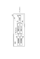
- FIG. 4 is a block diagram showing RRH of Related Technology 1. Hereinafter, description will be given based on this drawing.
- the RRH 30 is located between the transmission circuit unit 31 that outputs a transmission signal, the reception circuit unit 32 that receives a reception signal, the transmission circuit unit 31 and the reception circuit unit 32, and the antenna, and transmits only the transmission signal from the transmission circuit unit 31.
- a duplexer 33 that allows only a reception signal from the antenna to pass through the reception filter 35 to the reception circuit unit 32 through the transmission filter 34.
- the duplexer 33 transmits to the antenna a transmission filter 34 that passes only the signal of the transmission frequency, a reception filter 35 that passes only the signal of the reception frequency, and a signal received by the antenna. Is output to the reception filter 35.
- the RRH 30 has a transmission circuit unit 31 and a reception circuit unit 32 therein, and the transmission circuit unit 31 and the reception circuit unit 32 are connected via a duplexer 33 in which a combiner 36, a transmission filter 34, and a reception filter 35 are integrated. Connected with antenna.
- the transmission signal output from the transmission circuit unit 31 appears to be an extremely high level interference wave. For example, if the transmission output is RRH30 of 20 W, the difference between the minimum value of the reception signal and the maximum value of the transmission signal is 140 dB or more.
- the reception filter 35 needs to increase the attenuation amount (80 dB or more) of the frequency band of the transmission signal while reducing the attenuation amount (loss) of the frequency band of the reception signal.
- the transmission frequency and the reception frequency are different frequencies, the frequencies are close to some extent.
- the transmission frequency is 2110 to 2170 MHz
- the reception frequency is 1920 to 1980 MHz
- these distances are 190 MHz.
- the reception filter 35 has very steep characteristics. Necessary. There are several ways to achieve a steep filter, but if the material and processing accuracy are the same, it is necessary to increase the number of stages, and the filter with a steeper characteristic must be larger. .
- FIG. 5 is a block diagram showing a wireless communication system of Related Technology 2.
- FIG. 6 is a graph showing the filter characteristics of the reception filter in the related art 2.
- FIGS. 5 and 6 a description will be given based on FIGS. 5 and 6.
- the wireless communication system of the related technique 2 includes an RRH 40 and an RRH 50.
- the RRH 40 includes a transmission circuit unit 41 that outputs a first transmission signal having a transmission frequency TX1, a reception circuit unit 42 that inputs a first reception signal having a reception frequency RX1, a first transmission signal, and a first transmission signal. Between the antenna 47 for transmitting and receiving the reception signal, the transmission circuit unit 41, the reception circuit unit 42 and the antenna 47, only the first transmission signal from the transmission circuit unit 41 passes through the transmission filter 44 to the antenna 47. And a duplexer 43 that allows only the first reception signal from the antenna 47 to pass through the reception filter 45 to the reception circuit unit 42.
- the duplexer 43 outputs to the antenna 47 the transmission filter 44 that passes only the signal of the transmission frequency TX1, the reception filter 45 that passes only the signal of the reception frequency RX1, and the signal that has passed through the transmission filter 44. And a synthesizer 46 that outputs the received signal to the reception filter 45.
- the RRH 50 includes a transmission circuit unit 51 that outputs a second transmission signal having a transmission frequency TX2, a reception circuit unit 52 that inputs a second reception signal having a reception frequency RX2, a second transmission signal, and a second transmission signal. Between the antenna 57 for transmitting and receiving the reception signal, the transmission circuit unit 51 and the reception circuit unit 52 and the antenna 57, only the second transmission signal from the transmission circuit unit 51 passes through the transmission filter 54 to the antenna 57. And a duplexer 53 that allows only the second reception signal from the antenna 57 to pass through the reception filter 55 to the reception circuit unit 52.
- the duplexer 53 outputs to the antenna 57 the transmission filter 54 that passes only the signal of the transmission frequency TX2, the reception filter 55 that passes only the signal of the reception frequency RX2, and the signal that has passed the transmission filter 54. And a synthesizer 56 that outputs the received signal to the reception filter 55.
- the horizontal axis represents frequency
- the vertical axis represents filter attenuation.
- the attenuation amount of the reception filter 45 is indicated by a one-dot chain line
- the attenuation amount of the reception filter 55 is indicated by a two-dot chain line.
- the magnitude relationship between the transmission frequency TX1, the reception frequency RX1, the transmission frequency TX2, and the reception frequency RX2 is as follows. When the respective frequencies are fTX1, fRX1, fTX2, and fRX2, fRX1 ⁇ fTX1 ⁇ fRX2 ⁇ fTX2 It has become.
- carrier aggregation In LTE-Advanced, a technology called “carrier aggregation” that increases data transfer speed by considering a plurality of frequency bands as one transmission band is specified. In order to use this technique, it is necessary to operate two RRHs corresponding to two different frequency bands as a set. In the case of a high-power base station apparatus called “macro cell”, two RRHs are connected to one antenna via a combiner. The choice between multiple RRHs sharing one antenna through the combiner or individual RRHs using separate antennas is a trade-off between antenna cost and combiner cost.
- FIG. 5 shows the format. In this figure, two RRHs 40 and 50 are connected to separate antennas 47 and 57, respectively.
- a technique called “carrier aggregation” has been specified in which a plurality of frequency bands are considered as one transmission band and the data transfer rate is increased.
- two RRHs 40 and 50 corresponding to two frequency bands are prepared as shown in FIG.
- the positional relationship of each frequency band on the frequency axis is as shown in FIG.
- the reception filters 45 and 55 in the RRHs 40 and 50 are required to have the characteristics shown in FIG. 6 as described above.
- the reception filter 45 the attenuation amount of the band of the reception frequency RX1 is reduced, and the attenuation amount of the band of the transmission frequency TX1 is increased.
- the reception filter 55 the attenuation amount in the band of the reception frequency RX2 is reduced, and the attenuation amount in the band of the transmission frequency TX2 is increased. For this reason, it is necessary to make the slopes of the portions surrounded by the broken-line circles in FIG. 6 (between the reception frequency RX1 and the transmission frequency TX1 and between the reception frequency RX2 and the transmission frequency TX2) steep, The sizes of the reception filters 45 and 55 are determined.
- the ratio of the duplexers 13 and 23 in the total volume of the RRHs 40 and 50 is large (about 20 to 50%), and the size of the duplexers 13 and 23 affects the size of the RRHs 40 and 50 themselves.
- an object of the present invention is to provide a wireless communication system that can reduce the size of a reception filter used in a duplexer.
- a wireless communication system includes: A first wireless communication device and a second wireless communication device;
- the first wireless communication device is: A first transmission circuit unit for outputting a first transmission signal having a first transmission frequency; A first receiving circuit unit for inputting a first reception signal having a second reception frequency; A first antenna for transmitting and receiving the first transmission signal and the first reception signal; Between the first transmission circuit unit and the first reception circuit unit and the first antenna, only the first transmission signal from the first transmission circuit unit is passed through the first transmission filter.
- a first duplexer that passes through the first antenna and passes only the first reception signal from the first antenna through the first reception filter to the first reception circuit unit;
- the second wireless communication device is A second transmission circuit unit that outputs a second transmission signal having a second transmission frequency;
- a second receiving circuit unit for inputting a second received signal having the first receiving frequency;
- a second antenna for transmitting and receiving the second transmission signal and the second reception signal; Between the second transmission circuit unit and the second reception circuit unit and the second antenna, only the second transmission signal from the second transmission circuit unit is passed through the second transmission filter.
- a second duplexer that passes through the second antenna and passes only the second reception signal from the second antenna through the second reception filter to the second reception circuit unit; Have The difference between the first transmission frequency and the second reception frequency and the difference between the second transmission frequency and the first reception frequency are both the first transmission frequency and the first reception frequency. And greater than the difference between the second transmission frequency and the second reception frequency.
- the first reception filter separates the first transmission frequency and the first reception frequency and the second reception filter separates the second transmission frequency and the second reception frequency.
- the first reception filter separates the first transmission frequency and the second reception frequency and the second reception filter separates the second transmission frequency and the first reception frequency.
- the downsizing of the first and second reception filters in the invention can be achieved. The reason is that the difference between the first transmission frequency and the second reception frequency and the difference between the second transmission frequency and the first reception frequency are both the difference between the first transmission frequency and the first reception frequency. Greater than and greater than the difference between the second transmit frequency and the second receive frequency, the first and second receive filters in the present invention are compared to the first and second receive filters in the related art. This is because steep filter characteristics are not required.
- FIG. 1 is a block diagram illustrating a wireless communication system according to a first embodiment.
- 6 is a graph (part 1) illustrating filter characteristics of a reception filter according to the first embodiment.
- 6 is a graph (part 2) illustrating a filter characteristic of the reception filter according to the first embodiment.
- It is a block diagram which shows RRH of related technology 1.
- It is a block diagram which shows the radio
- FIG. 10 is a graph showing filter characteristics of a reception filter in Related Art 2.
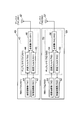
- FIG. 1 is a block diagram illustrating a wireless communication system according to the first embodiment.
- FIG. 2 is a graph (part 1) illustrating filter characteristics of the reception filter according to the first embodiment.
- FIG. 3 is a graph (part 2) illustrating the filter characteristics of the reception filter according to the first embodiment.
- the wireless communication system includes an RRH 10 as a first wireless communication device and an RRH 20 as a second wireless communication device.
- the RRH 10 corresponds to the first transmission frequency TX1 and the second reception frequency RX2.
- the first transmission circuit unit 11 is an electric circuit corresponding to the transmission frequency TX1.
- the first receiving circuit unit 12 is an electric circuit corresponding to the receiving frequency RX2.
- the first duplexer 13 corresponds to the transmission frequency TX1 and the reception frequency RX2.
- the first transmission filter 14 is a bandpass filter corresponding to the transmission frequency TX1.
- the first reception filter 15 is a bandpass filter corresponding to the reception frequency RX2.
- the first combiner 16 connects the transmission circuit unit 11 side and the reception circuit unit 12 side.
- the first antenna 17 is for the RRH 10 that uses the transmission frequency TX1 and the reception frequency RX2.
- the RRH 20 corresponds to the second transmission frequency TX2 and the first reception frequency RX1.
- the second transmission circuit unit 21 is an electric circuit corresponding to the transmission frequency TX2.
- the second receiving circuit unit 22 is an electric circuit corresponding to the receiving frequency RX1.
- the second duplexer 23 corresponds to the transmission frequency TX2 and the reception frequency RX1.
- the second transmission filter 24 is a bandpass filter corresponding to the transmission frequency TX2.
- the second reception filter 25 is a bandpass filter corresponding to the reception frequency RX1.
- the second synthesizer 16 connects the transmission circuit unit 21 side and the reception circuit unit 22 side.
- the second antenna 27 is for the RRH 20 that uses the transmission frequency TX2 and the reception frequency RX1.
- the RRH 10 includes a transmission circuit unit 11 that outputs a first transmission signal having a transmission frequency TX1, a reception circuit unit 12 that inputs a first reception signal having a reception frequency RX2, a first transmission signal, and An antenna 17 that transmits and receives the first reception signal, and between the transmission circuit unit 11 and the reception circuit unit 12 and the antenna 17, only the first transmission signal from the transmission circuit unit 11 is transmitted via the transmission filter 14 to the antenna. And a duplexer 13 that passes only the first reception signal from the antenna 17 to the reception circuit unit 12 through the reception filter 15.
- the duplexer 13 outputs to the antenna 17 a transmission filter 14 that passes only the signal of the transmission frequency TX 2, a reception filter 15 that passes only the signal of the reception frequency RX 2, and a signal that has passed the transmission filter 14. And a synthesizer 16 that outputs the received signal to the reception filter 15.
- the RRH 20 includes a transmission circuit unit 21 that outputs a second transmission signal having a transmission frequency TX2, a reception circuit unit 22 that inputs a second reception signal having a reception frequency RX1, a second transmission signal, and Between the antenna 27 for transmitting and receiving the second received signal, and between the transmitting circuit unit 21 and the receiving circuit unit 22 and the antenna 27, only the second transmitted signal from the transmitting circuit unit 21 is transmitted via the transmission filter 24 to the antenna. And a duplexer 23 that allows only the second received signal from the antenna 27 to pass through the reception filter 25 to the reception circuit unit 22.
- the duplexer 23 outputs to the antenna 27 the transmission filter 24 that passes only the signal of the transmission frequency TX2, the reception filter 25 that passes only the signal of the reception frequency RX2, and the signal that has passed through the transmission filter 24. And a synthesizer 26 that outputs the received signal to the reception filter 25.
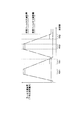
- the horizontal axis represents frequency
- the vertical axis represents filter attenuation.
- the attenuation amount of the reception filter 25 is indicated by a one-dot chain line
- the attenuation amount of the reception filter 15 is indicated by a two-dot chain line.
- the magnitude relationship between the transmission frequency TX1, the reception frequency RX1, the transmission frequency TX2, and the reception frequency RX2 is as follows. When the respective frequencies are fTX1, fRX1, fTX2, and fRX2, fRX1 ⁇ fTX1 ⁇ fRX2 ⁇ fTX2 It has become.
- the difference f (TX1-RX2) between the transmission frequency TX1 and the reception frequency RX2 and the difference f (TX2-RX1) between the transmission frequency TX2 and the reception frequency RX1 are both the difference f between the transmission frequency TX1 and the reception frequency RX1. It is larger than (TX1-RX1) and larger than the difference f (TX2-RX2) between the transmission frequency TX2 and the reception frequency RX2.
- the reception filter 45 separates the transmission frequency TX1 and the reception frequency RX1 and the reception filter 55 separates the transmission frequency TX2 and the reception frequency RX2, whereas the present embodiment shown in FIG. 1, the reception filter 15 separates the transmission frequency TX1 and the reception frequency RX2, and the reception filter 25 separates the transmission frequency TX2 and the reception frequency RX1, thereby reducing the size of the reception filters 15 and 25 in the first embodiment. Can be achieved.
- the reason is that the difference f (TX1-RX2) between the transmission frequency TX1 and the reception frequency RX2 and the difference f (TX2-RX1) between the transmission frequency TX2 and the reception frequency RX1 are both between the transmission frequency TX1 and the reception frequency RX1.
- the reception filters 15 and 25 in the first embodiment are the reception filters in the related technique 2. This is because a steep filter characteristic is not required as compared with 45 and 55.
- two RRHs 40 and 50 having the configuration shown in FIG. 5 are used.
- two RRHs 10 and 20 having the configuration shown in FIG. 1 are prepared instead.
- the RRHs 10 and 20 having the configuration shown in FIG. 1 are not useful when considering operation with one unit, but the configuration of FIG. 5 and the configuration of FIG. 1 have the same functions when considering operation as a system with two sets. Fulfill (no functional advantage or disadvantage)
- the transmission circuit unit 41 and the reception circuit unit 42 connected via the duplexer 43 use the transmission frequency TX1 and the reception frequency RX1
- the transmission circuit unit 11 and the reception circuit unit 12 connected via the duplexer 13 use the transmission frequency TX1 and the reception frequency RX2. Therefore, the required attenuation amount of the reception filter 15 in the first embodiment also changes as shown in FIG. That is, for the reception filter 15, the attenuation amount in the band of the reception frequency RX2 is reduced, and the attenuation amount in the band of the transmission frequency TX1 is increased.
- the slope of the filter characteristic is the reception filter 45.
- the reception filter 15 can be loosened.
- the other reception filter 25 in the first embodiment Thereby, the number of reception filters 15 and 25 can be reduced, and thus the reception filters 15 and 25 can be reduced in size.
- the configuration of the first embodiment has little meaning to be applied in the case of an operation mode in which two RRHs share one antenna at the time of carrier aggregation. This is because the connection through the antenna results in the same connection as in the configuration of FIG. Since a spatial isolation between antennas can be obtained by adopting an operation mode in which separate antennas are attached to individual RRHs in a small cell, such a design can be applied.
- the standard of the attenuation amount of the band of the transmission frequency TX1 in the reception filter 25 is a value obtained by subtracting the value of the spatial isolation as it is from the original standard.
- the amount of spatial isolation varies greatly depending on the antenna arrangement and the like. However, since the value is about 30 dB to 60 dB, the standard relaxation amount is also the value.
- the filter unit can be downsized and the device itself can be downsized by designing a set of two models on the premise of multiband operation in the mobile phone base station RRH.
- the present invention has been described above with reference to the above embodiment, but the present invention is not limited to the above embodiment. Various changes that can be understood by those skilled in the art can be made to the configuration and details of the present invention. In addition, the present invention includes a combination of some or all of the configurations of the above embodiments as appropriate.
- a first wireless communication device and a second wireless communication device are provided,
- the first wireless communication device is: A first transmission circuit unit for outputting a first transmission signal having a first transmission frequency; A first receiving circuit unit for inputting a first reception signal having a second reception frequency; A first antenna for transmitting and receiving the first transmission signal and the first reception signal; Between the first transmission circuit unit and the first reception circuit unit and the first antenna, only the first transmission signal from the first transmission circuit unit is passed through the first transmission filter.
- the second wireless communication device is A second transmission circuit unit that outputs a second transmission signal having a second transmission frequency; A second receiving circuit unit for inputting a second received signal having the first receiving frequency; A second antenna for transmitting and receiving the second transmission signal and the second reception signal; Between the second transmission circuit unit and the second reception circuit unit and the second antenna, only the second transmission signal from the second transmission circuit unit through the second transmission filter
- the difference between the first transmission frequency and the second reception frequency and the difference between the second transmission frequency and the first reception frequency are both the first transmission frequency and the first reception frequency. Greater than the difference between the second transmission frequency and the second reception frequency, Wireless communication system.
- the first duplexer is: The first transmission filter that passes only the signal of the first transmission frequency; and The first reception filter that passes only the signal of the second reception frequency; and A first combiner that outputs a signal that has passed through the first transmission filter to the first antenna, and that outputs a signal received by the first antenna to the first reception filter;
- the second duplexer is The second transmission filter that passes only the signal of the second transmission frequency; and The second reception filter that passes only the signal of the first reception frequency; and A second combiner that outputs a signal that has passed through the second transmission filter to the second antenna, and that outputs a signal received by the second antenna to the second reception filter; Having The wireless communication system according to attachment 1.
- the first wireless communication device and the second wireless communication device are RRHs (Remote Radio Heads) for mobile phone base stations, respectively.
- RRHs Remote Radio Heads
- the wireless communication system according to appendix 1 or 2.
- the first transmission frequency is fTX1
- the first reception frequency is fRX1
- the second transmission frequency is fTX2
- the second reception frequency is fRX2
- the following four magnitude relationships are obtained. Including, fRX1 ⁇ fTX1 ⁇ fRX2 ⁇ fTX2, fRX1 ⁇ fTX1 ⁇ fTX2 ⁇ fRX2, fTX1 ⁇ fRX1 ⁇ fRX2 ⁇ fTX2, fTX1 ⁇ fRX1 ⁇ fTX2 ⁇ fRX2,
- the wireless communication system according to appendix 1, 2, or 3.
- the present invention can be used for a wireless communication system including a wireless communication device such as RRH (Remote Radio Head) for mobile phone base stations.
- RRH Remote Radio Head
- TX1, RX2 Transmitter circuit
- TX1 Receiver circuit part
- RX2 Duplexer
- TX1 Receive filter
- RX2 Synthesizer
- TX1, RX2 Antenna
- TX1, RX1 Transmitter circuit
- TX1 Receiver circuit section
- RX1 Receiver circuit section
- TX1 Duplexer
- TX1 Transmission filter
- RX1 Receive filter
- TX1 Synthesizer
- TX1, RX1 Antenna
- TX2, RX2 RRH
- TX2 Transmitter circuit
- RX2 Receiver circuit section
- TX2 Duplexer
- TX2 Transmission filter
- TX2 Receive Filter
- RX2 Synthesizer
- TX2, RX2 Antenna
Abstract
Description
fRX1<fTX1<fRX2<fTX2
となっている。 In FIG. 6, the horizontal axis represents frequency, and the vertical axis represents filter attenuation. The attenuation amount of the
fRX1 <fTX1 <fRX2 <fTX2
It has become.
第一の無線通信装置及び第二の無線通信装置を備え、
前記第一の無線通信装置は、
第一の送信周波数からなる第一の送信信号を出力する第一の送信回路部と、
第二の受信周波数からなる第一の受信信号を入力する第一の受信回路部と、
前記第一の送信信号及び前記第一の受信信号を送信及び受信する第一のアンテナと、
前記第一の送信回路部及び前記第一の受信回路部と前記第一のアンテナとの間にあって、前記第一の送信回路部から第一の送信信号のみを第一の送信フィルタを介して前記第一のアンテナへ通過させるとともに、前記第一のアンテナから第一の受信信号のみを第一の受信フィルタを介して前記第一の受信回路部へ通過させる第一のデュプレクサと、
を有し、
前記第二の無線通信装置は、
第二の送信周波数からなる第二の送信信号を出力する第二の送信回路部と、
第一の受信周波数からなる第二の受信信号を入力する第二の受信回路部と、
前記第二の送信信号及び前記第二の受信信号を送信及び受信する第二のアンテナと、
前記第二の送信回路部及び前記第二の受信回路部と前記第二のアンテナとの間にあって、前記第二の送信回路部から第二の送信信号のみを第二の送信フィルタを介して前記第二のアンテナへ通過させるとともに、前記第二のアンテナから第二の受信信号のみを第二の受信フィルタを介して前記第二の受信回路部へ通過させる第二のデュプレクサと、
を有し、
前記第一送信周波数と前記第二の受信周波数との差及び前記第二の送信周波数と前記第一の受信周波数との差は、いずれも前記第一の送信周波数と前記第一の受信周波数との差よりも大きくかつ前記第二の送信周波数と前記第二の受信周波数との差よりも大きい。 A wireless communication system according to the present invention includes:
A first wireless communication device and a second wireless communication device;
The first wireless communication device is:
A first transmission circuit unit for outputting a first transmission signal having a first transmission frequency;
A first receiving circuit unit for inputting a first reception signal having a second reception frequency;
A first antenna for transmitting and receiving the first transmission signal and the first reception signal;
Between the first transmission circuit unit and the first reception circuit unit and the first antenna, only the first transmission signal from the first transmission circuit unit is passed through the first transmission filter. A first duplexer that passes through the first antenna and passes only the first reception signal from the first antenna through the first reception filter to the first reception circuit unit;
Have
The second wireless communication device is
A second transmission circuit unit that outputs a second transmission signal having a second transmission frequency;
A second receiving circuit unit for inputting a second received signal having the first receiving frequency;
A second antenna for transmitting and receiving the second transmission signal and the second reception signal;
Between the second transmission circuit unit and the second reception circuit unit and the second antenna, only the second transmission signal from the second transmission circuit unit is passed through the second transmission filter. A second duplexer that passes through the second antenna and passes only the second reception signal from the second antenna through the second reception filter to the second reception circuit unit;
Have
The difference between the first transmission frequency and the second reception frequency and the difference between the second transmission frequency and the first reception frequency are both the first transmission frequency and the first reception frequency. And greater than the difference between the second transmission frequency and the second reception frequency.
fRX1<fTX1<fRX2<fTX2
となっている。 2 and 3, the horizontal axis represents frequency, and the vertical axis represents filter attenuation. The attenuation amount of the
fRX1 <fTX1 <fRX2 <fTX2
It has become.
fRX1<fTX1<fTX2<fRX2、
fTX1<fRX1<fRX2<fTX2、
fTX1<fRX1<fTX2<fRX2。 The following combinations are possible for the above magnitude relationship.
fRX1 <fTX1 <fTX2 <fRX2,
fTX1 <fRX1 <fRX2 <fTX2,
fTX1 <fRX1 <fTX2 <fRX2.
前記第一の無線通信装置は、
第一の送信周波数からなる第一の送信信号を出力する第一の送信回路部と、
第二の受信周波数からなる第一の受信信号を入力する第一の受信回路部と、
前記第一の送信信号及び前記第一の受信信号を送信及び受信する第一のアンテナと、
前記第一の送信回路部及び前記第一の受信回路部と前記第一のアンテナとの間にあって、前記第一の送信回路部から前記第一の送信信号のみを第一の送信フィルタを介して前記第一のアンテナへ通過させるとともに、前記第一のアンテナから前記第一の受信信号のみを第一の受信フィルタを介して前記第一の受信回路部へ通過させる第一のデュプレクサと、
を有し、
前記第二の無線通信装置は、
第二の送信周波数からなる第二の送信信号を出力する第二の送信回路部と、
第一の受信周波数からなる第二の受信信号を入力する第二の受信回路部と、
前記第二の送信信号及び前記第二の受信信号を送信及び受信する第二のアンテナと、
前記第二の送信回路部及び前記第二の受信回路部と前記第二のアンテナとの間にあって、前記第二の送信回路部から前記第二の送信信号のみを第二の送信フィルタを介して前記第二のアンテナへ通過させるとともに、前記第二のアンテナから前記第二の受信信号のみを第二の受信フィルタを介して前記第二の受信回路部へ通過させる第二のデュプレクサと、
を有し、
前記第一送信周波数と前記第二の受信周波数との差及び前記第二の送信周波数と前記第一の受信周波数との差は、いずれも前記第一の送信周波数と前記第一の受信周波数との差よりも大きくかつ前記第二の送信周波数と前記第二の受信周波数との差よりも大きい、
無線通信システム。 [Supplementary Note 1] A first wireless communication device and a second wireless communication device are provided,
The first wireless communication device is:
A first transmission circuit unit for outputting a first transmission signal having a first transmission frequency;
A first receiving circuit unit for inputting a first reception signal having a second reception frequency;
A first antenna for transmitting and receiving the first transmission signal and the first reception signal;
Between the first transmission circuit unit and the first reception circuit unit and the first antenna, only the first transmission signal from the first transmission circuit unit is passed through the first transmission filter. A first duplexer that passes through the first antenna and passes only the first reception signal from the first antenna through the first reception filter to the first reception circuit unit;
Have
The second wireless communication device is
A second transmission circuit unit that outputs a second transmission signal having a second transmission frequency;
A second receiving circuit unit for inputting a second received signal having the first receiving frequency;
A second antenna for transmitting and receiving the second transmission signal and the second reception signal;
Between the second transmission circuit unit and the second reception circuit unit and the second antenna, only the second transmission signal from the second transmission circuit unit through the second transmission filter A second duplexer that passes through the second antenna and passes only the second received signal from the second antenna through the second receiving filter to the second receiving circuit unit;
Have
The difference between the first transmission frequency and the second reception frequency and the difference between the second transmission frequency and the first reception frequency are both the first transmission frequency and the first reception frequency. Greater than the difference between the second transmission frequency and the second reception frequency,
Wireless communication system.
前記第一の送信周波数の信号のみを通過させる前記第一の送信フィルタと、
前記第二の受信周波数の信号のみを通過させる前記第一の受信フィルタと、
前記第一の送信フィルタを通過した信号を前記第一アンテナへ出力するとともに、前記第一のアンテナで受信された信号を前記第一の受信フィルタへ出力する第一の合成器と、
を有し、
前記第二のデュプレクサは、
前記第二の送信周波数の信号のみを通過させる前記第二の送信フィルタと、
前記第一の受信周波数の信号のみを通過させる前記第二の受信フィルタと、
前記第二の送信フィルタを通過した信号を前記第二のアンテナへ出力するとともに、前記第二のアンテナで受信された信号を前記第二の受信フィルタへ出力する第二の合成器と、
を有する、
付記1記載の無線通信システム。 [Appendix 2] The first duplexer is:
The first transmission filter that passes only the signal of the first transmission frequency; and
The first reception filter that passes only the signal of the second reception frequency; and
A first combiner that outputs a signal that has passed through the first transmission filter to the first antenna, and that outputs a signal received by the first antenna to the first reception filter;
Have
The second duplexer is
The second transmission filter that passes only the signal of the second transmission frequency; and
The second reception filter that passes only the signal of the first reception frequency; and
A second combiner that outputs a signal that has passed through the second transmission filter to the second antenna, and that outputs a signal received by the second antenna to the second reception filter;
Having
The wireless communication system according to
付記1又は2記載の無線通信システム。 [Appendix 3] The first wireless communication device and the second wireless communication device are RRHs (Remote Radio Heads) for mobile phone base stations, respectively.
The wireless communication system according to
fRX1<fTX1<fRX2<fTX2、
fRX1<fTX1<fTX2<fRX2、
fTX1<fRX1<fRX2<fTX2、
fTX1<fRX1<fTX2<fRX2、
付記1、2又は3記載の無線通信システム。 [Supplementary Note 4] When the first transmission frequency is fTX1, the first reception frequency is fRX1, the second transmission frequency is fTX2, and the second reception frequency is fRX2, the following four magnitude relationships are obtained. Including,
fRX1 <fTX1 <fRX2 <fTX2,
fRX1 <fTX1 <fTX2 <fRX2,
fTX1 <fRX1 <fRX2 <fTX2,
fTX1 <fRX1 <fTX2 <fRX2,
The wireless communication system according to
11 送信回路部(TX1)
12 受信回路部(RX2)
13 デュプレクサ(TX1,RX2)
14 送信フィルタ(TX1)
15 受信フィルタ(RX2)
16 合成器(TX1,RX2)
17 アンテナ(TX1,RX2) 10 RRH (TX1, RX2)
11 Transmitter circuit (TX1)
12 Receiver circuit part (RX2)
13 Duplexer (TX1, RX2)
14 Transmission filter (TX1)
15 Receive filter (RX2)
16 Synthesizer (TX1, RX2)
17 Antenna (TX1, RX2)
21 送信回路部(TX2)
22 受信回路部(RX1)
23 デュプレクサ(TX2,RX1)
24 送信フィルタ(TX2)
25 受信フィルタ(RX1)
26 合成器(TX2,RX1)
27 アンテナ(TX2,RX1) 20 RRH (TX2, RX1)
21 Transmitter circuit (TX2)
22 Receiver circuit part (RX1)
23 Duplexer (TX2, RX1)
24 Transmission filter (TX2)
25 Receive filter (RX1)
26 Synthesizer (TX2, RX1)
27 Antenna (TX2, RX1)
31 送信回路部
32 受信回路部
33 デュプレクサ
34 送信フィルタ
35 受信フィルタ
36 合成器 30 RRH
31
41 送信回路部(TX1)
42 受信回路部(RX1)
43 デュプレクサ(TX1,RX1)
44 送信フィルタ(TX1)
45 受信フィルタ(RX1)
46 合成器(TX1,RX1)
47 アンテナ(TX1,RX1) 40 RRH (TX1, RX1)
41 Transmitter circuit (TX1)
42 Receiver circuit section (RX1)
43 Duplexer (TX1, RX1)
44 Transmission filter (TX1)
45 Receive filter (RX1)
46 Synthesizer (TX1, RX1)
47 Antenna (TX1, RX1)
51 送信回路部(TX2)
52 受信回路部(RX2)
53 デュプレクサ(TX2,RX2)
54 送信フィルタ(TX2)
55 受信フィルタ(RX2)
56 合成器(TX2,RX2)
57 アンテナ(TX2,RX2) 50 RRH (TX2, RX2)
51 Transmitter circuit (TX2)
52 Receiver circuit section (RX2)
53 Duplexer (TX2, RX2)
54 Transmission filter (TX2)
55 Receive Filter (RX2)
56 Synthesizer (TX2, RX2)
57 Antenna (TX2, RX2)
Claims (4)
- 第一の無線通信装置及び第二の無線通信装置を備え、
前記第一の無線通信装置は、
第一の送信周波数からなる第一の送信信号を出力する第一の送信回路部と、
第二の受信周波数からなる第一の受信信号を入力する第一の受信回路部と、
前記第一の送信信号及び前記第一の受信信号を送信及び受信する第一のアンテナと、
前記第一の送信回路部及び前記第一の受信回路部と前記第一のアンテナとの間にあって、前記第一の送信回路部から前記第一の送信信号のみを第一の送信フィルタを介して前記第一のアンテナへ通過させるとともに、前記第一のアンテナから前記第一の受信信号のみを第一の受信フィルタを介して前記第一の受信回路部へ通過させる第一のデュプレクサと、
を有し、
前記第二の無線通信装置は、
第二の送信周波数からなる第二の送信信号を出力する第二の送信回路部と、
第一の受信周波数からなる第二の受信信号を入力する第二の受信回路部と、
前記第二の送信信号及び前記第二の受信信号を送信及び受信する第二のアンテナと、
前記第二の送信回路部及び前記第二の受信回路部と前記第二のアンテナとの間にあって、前記第二の送信回路部から前記第二の送信信号のみを第二の送信フィルタを介して前記第二のアンテナへ通過させるとともに、前記第二のアンテナから前記第二の受信信号のみを第二の受信フィルタを介して前記第二の受信回路部へ通過させる第二のデュプレクサと、
を有し、
前記第一送信周波数と前記第二の受信周波数との差及び前記第二の送信周波数と前記第一の受信周波数との差は、いずれも前記第一の送信周波数と前記第一の受信周波数との差よりも大きくかつ前記第二の送信周波数と前記第二の受信周波数との差よりも大きい、
無線通信システム。 A first wireless communication device and a second wireless communication device;
The first wireless communication device is:
A first transmission circuit unit for outputting a first transmission signal having a first transmission frequency;
A first receiving circuit unit for inputting a first reception signal having a second reception frequency;
A first antenna for transmitting and receiving the first transmission signal and the first reception signal;
Between the first transmission circuit unit and the first reception circuit unit and the first antenna, only the first transmission signal from the first transmission circuit unit is passed through the first transmission filter. A first duplexer that passes through the first antenna and passes only the first reception signal from the first antenna through the first reception filter to the first reception circuit unit;
Have
The second wireless communication device is
A second transmission circuit unit that outputs a second transmission signal having a second transmission frequency;
A second receiving circuit unit for inputting a second received signal having the first receiving frequency;
A second antenna for transmitting and receiving the second transmission signal and the second reception signal;
Between the second transmission circuit unit and the second reception circuit unit and the second antenna, only the second transmission signal from the second transmission circuit unit is passed through the second transmission filter. A second duplexer that passes through the second antenna and passes only the second received signal from the second antenna through the second receiving filter to the second receiving circuit unit;
Have
The difference between the first transmission frequency and the second reception frequency and the difference between the second transmission frequency and the first reception frequency are both the first transmission frequency and the first reception frequency. Greater than the difference between the second transmission frequency and the second reception frequency,
Wireless communication system. - 前記第一のデュプレクサは、
前記第一の送信周波数の信号のみを通過させる前記第一の送信フィルタと、
前記第二の受信周波数の信号のみを通過させる前記第一の受信フィルタと、
前記第一の送信フィルタを通過した信号を前記第一アンテナへ出力するとともに、前記第一のアンテナで受信された信号を前記第一の受信フィルタへ出力する第一の合成器と、
を有し、
前記第二のデュプレクサは、
前記第二の送信周波数の信号のみを通過させる前記第二の送信フィルタと、
前記第一の受信周波数の信号のみを通過させる前記第二の受信フィルタと、
前記第二の送信フィルタを通過した信号を前記第二のアンテナへ出力するとともに、前記第二のアンテナで受信された信号を前記第二の受信フィルタへ出力する第二の合成器と、
を有する、
請求項1記載の無線通信システム。 The first duplexer is:
The first transmission filter that passes only the signal of the first transmission frequency; and
The first reception filter that passes only the signal of the second reception frequency; and
A first combiner that outputs a signal that has passed through the first transmission filter to the first antenna, and that outputs a signal received by the first antenna to the first reception filter;
Have
The second duplexer is
The second transmission filter that passes only the signal of the second transmission frequency; and
The second reception filter that passes only the signal of the first reception frequency; and
A second combiner that outputs a signal that has passed through the second transmission filter to the second antenna, and that outputs a signal received by the second antenna to the second reception filter;
Having
The wireless communication system according to claim 1. - 第一の無線通信装置及び第二の無線通信装置はそれぞれ携帯電話基地局用のRRH(Remote
Radio Head)である、
請求項1又は2記載の無線通信システム。 Each of the first wireless communication device and the second wireless communication device is an RRH (Remote
Radio Head)
The wireless communication system according to claim 1 or 2. - 前記第一送信周波数をfTX1、前記第一の受信周波数をfRX1、前記第二の送信周波数をfTX2、前記第二の受信周波数をfRX2としたとき、次の四通りの大小関係を含む、
fRX1<fTX1<fRX2<fTX2、
fRX1<fTX1<fTX2<fRX2、
fTX1<fRX1<fRX2<fTX2、
fTX1<fRX1<fTX2<fRX2、
請求項1、2又は3記載の無線通信システム。 When the first transmission frequency is fTX1, the first reception frequency is fRX1, the second transmission frequency is fTX2, and the second reception frequency is fRX2, the following four magnitude relationships are included:
fRX1 <fTX1 <fRX2 <fTX2,
fRX1 <fTX1 <fTX2 <fRX2,
fTX1 <fRX1 <fRX2 <fTX2,
fTX1 <fRX1 <fTX2 <fRX2,
The wireless communication system according to claim 1, 2 or 3.
Priority Applications (3)
| Application Number | Priority Date | Filing Date | Title |
|---|---|---|---|
| EP14775250.5A EP2980997A4 (en) | 2013-03-26 | 2014-03-26 | Wireless communication system |
| JP2015508587A JPWO2014157330A1 (en) | 2013-03-26 | 2014-03-26 | Wireless communication system |
| US14/780,143 US20160043821A1 (en) | 2013-03-26 | 2014-03-26 | Wireless communication system |
Applications Claiming Priority (2)
| Application Number | Priority Date | Filing Date | Title |
|---|---|---|---|
| JP2013063908 | 2013-03-26 | ||
| JP2013-063908 | 2013-03-26 |
Publications (1)
| Publication Number | Publication Date |
|---|---|
| WO2014157330A1 true WO2014157330A1 (en) | 2014-10-02 |
Family
ID=51624293
Family Applications (1)
| Application Number | Title | Priority Date | Filing Date |
|---|---|---|---|
| PCT/JP2014/058522 WO2014157330A1 (en) | 2013-03-26 | 2014-03-26 | Wireless communication system |
Country Status (4)
| Country | Link |
|---|---|
| US (1) | US20160043821A1 (en) |
| EP (1) | EP2980997A4 (en) |
| JP (1) | JPWO2014157330A1 (en) |
| WO (1) | WO2014157330A1 (en) |
Citations (5)
| Publication number | Priority date | Publication date | Assignee | Title |
|---|---|---|---|---|
| JP2000059106A (en) * | 1998-08-11 | 2000-02-25 | Murata Mfg Co Ltd | Antenna multicoupler and communication equipment |
| JP2010278886A (en) * | 2009-05-29 | 2010-12-09 | National Institute Of Information & Communication Technology | Terrestrial/satellite shared cellular phone system and system interference reduction method thereof |
| JP2012004725A (en) * | 2010-06-15 | 2012-01-05 | Renesas Electronics Corp | Semiconductor integrated circuit device and wireless communication system |
| JP2012514387A (en) * | 2008-12-24 | 2012-06-21 | ホリンワース ファンド,エル.エル.シー. | RF front end module and antenna system |
| JP2012222467A (en) | 2011-04-05 | 2012-11-12 | Ntt Docomo Inc | User device in mobile communication system |
Family Cites Families (3)
| Publication number | Priority date | Publication date | Assignee | Title |
|---|---|---|---|---|
| JP2012253497A (en) * | 2011-06-01 | 2012-12-20 | Taiyo Yuden Co Ltd | Electronic circuit and electronic module |
| US8892057B2 (en) * | 2011-08-23 | 2014-11-18 | Rf Micro Devices, Inc. | Carrier aggregation radio system |
| US8750792B2 (en) * | 2012-07-26 | 2014-06-10 | Remec Broadband Wireless, Llc | Transmitter for point-to-point radio system |
-
2014
- 2014-03-26 JP JP2015508587A patent/JPWO2014157330A1/en active Pending
- 2014-03-26 WO PCT/JP2014/058522 patent/WO2014157330A1/en active Application Filing
- 2014-03-26 EP EP14775250.5A patent/EP2980997A4/en not_active Withdrawn
- 2014-03-26 US US14/780,143 patent/US20160043821A1/en not_active Abandoned
Patent Citations (5)
| Publication number | Priority date | Publication date | Assignee | Title |
|---|---|---|---|---|
| JP2000059106A (en) * | 1998-08-11 | 2000-02-25 | Murata Mfg Co Ltd | Antenna multicoupler and communication equipment |
| JP2012514387A (en) * | 2008-12-24 | 2012-06-21 | ホリンワース ファンド,エル.エル.シー. | RF front end module and antenna system |
| JP2010278886A (en) * | 2009-05-29 | 2010-12-09 | National Institute Of Information & Communication Technology | Terrestrial/satellite shared cellular phone system and system interference reduction method thereof |
| JP2012004725A (en) * | 2010-06-15 | 2012-01-05 | Renesas Electronics Corp | Semiconductor integrated circuit device and wireless communication system |
| JP2012222467A (en) | 2011-04-05 | 2012-11-12 | Ntt Docomo Inc | User device in mobile communication system |
Non-Patent Citations (1)
| Title |
|---|
| See also references of EP2980997A4 |
Also Published As
| Publication number | Publication date |
|---|---|
| EP2980997A1 (en) | 2016-02-03 |
| EP2980997A4 (en) | 2016-12-14 |
| US20160043821A1 (en) | 2016-02-11 |
| JPWO2014157330A1 (en) | 2017-02-16 |
Similar Documents
| Publication | Publication Date | Title |
|---|---|---|
| TWI820945B (en) | Power detection of individual carrier of aggregated carrier | |
| CN108718219B (en) | Anti-harmonic interference device for carrier aggregation, antenna device and mobile terminal | |
| TWI672912B (en) | Electronic system, power amplifier system, packaged module, mobile device, electronically-implemented method of providing radio frequency signals to an antenna and front end | |
| US11736140B2 (en) | Mixed signal low noise interference cancellation | |
| US20230344456A1 (en) | Radio frequency communication systems with coexistence management based on digital observation data | |
| US20140328222A1 (en) | Interference cancellation method and apparatus, filter device | |
| US11784419B2 (en) | Antenna-plexer for interference cancellation | |
| US20140227982A1 (en) | Front end circuitry for carrier aggregation configurations | |
| JP6049687B2 (en) | Same band combiner using dual bandpass channel filter | |
| US8432836B2 (en) | Wireless circuitry with simultaneous voice and data capabilities and reduced intermodulation distortion | |
| US10057044B2 (en) | Front-end circuit | |
| GB2607770A (en) | Radio frequency communication systems with discrete time cancellation for coexistence management | |
| WO2016104234A1 (en) | High-frequency front end circuit and communication device | |
| JP2020123968A (en) | Mobile communication device with commonly used filter, method of operating the same, and use of filter | |
| US8600316B2 (en) | Wireless circuits with minimized port counts | |
| US20160254828A1 (en) | High-frequency front end circuit | |
| JP2012034049A (en) | Portable radio device | |
| WO2014157330A1 (en) | Wireless communication system | |
| CN215120767U (en) | Three-way antenna multiplexer applied to carrier aggregation | |
| CN101207874A (en) | Stand-by communication device simultaneous for code division multiple access and global mobile communication system | |
| US9172403B2 (en) | Reducing port requirement of antenna switch in multi-band electronic apparatus | |
| JP2003168995A (en) | Communication device | |
| KR20070066442A (en) | Transmitter-receiver for a mobile phone |
Legal Events
| Date | Code | Title | Description |
|---|---|---|---|
| 121 | Ep: the epo has been informed by wipo that ep was designated in this application |
Ref document number: 14775250 Country of ref document: EP Kind code of ref document: A1 |
|
| WWE | Wipo information: entry into national phase |
Ref document number: 2014775250 Country of ref document: EP |
|
| ENP | Entry into the national phase |
Ref document number: 2015508587 Country of ref document: JP Kind code of ref document: A |
|
| WWE | Wipo information: entry into national phase |
Ref document number: 14780143 Country of ref document: US |
|
| NENP | Non-entry into the national phase |
Ref country code: DE |