WO2014156607A1 - 眼用レンズ、眼用レンズの設計方法および眼用レンズの製造方法 - Google Patents
眼用レンズ、眼用レンズの設計方法および眼用レンズの製造方法 Download PDFInfo
- Publication number
- WO2014156607A1 WO2014156607A1 PCT/JP2014/056287 JP2014056287W WO2014156607A1 WO 2014156607 A1 WO2014156607 A1 WO 2014156607A1 JP 2014056287 W JP2014056287 W JP 2014056287W WO 2014156607 A1 WO2014156607 A1 WO 2014156607A1
- Authority
- WO
- WIPO (PCT)
- Prior art keywords
- lens
- region
- transmittance
- light
- apodization
- Prior art date
- Legal status (The legal status is an assumption and is not a legal conclusion. Google has not performed a legal analysis and makes no representation as to the accuracy of the status listed.)
- Ceased
Links
Images








Classifications
-
- A—HUMAN NECESSITIES
- A61—MEDICAL OR VETERINARY SCIENCE; HYGIENE
- A61F—FILTERS IMPLANTABLE INTO BLOOD VESSELS; PROSTHESES; DEVICES PROVIDING PATENCY TO, OR PREVENTING COLLAPSING OF, TUBULAR STRUCTURES OF THE BODY, e.g. STENTS; ORTHOPAEDIC, NURSING OR CONTRACEPTIVE DEVICES; FOMENTATION; TREATMENT OR PROTECTION OF EYES OR EARS; BANDAGES, DRESSINGS OR ABSORBENT PADS; FIRST-AID KITS
- A61F2/00—Filters implantable into blood vessels; Prostheses, i.e. artificial substitutes or replacements for parts of the body; Appliances for connecting them with the body; Devices providing patency to, or preventing collapsing of, tubular structures of the body, e.g. stents
- A61F2/02—Prostheses implantable into the body
- A61F2/14—Eye parts, e.g. lenses or corneal implants; Artificial eyes
- A61F2/16—Intraocular lenses
- A61F2/1613—Intraocular lenses having special lens configurations, e.g. multipart lenses; having particular optical properties, e.g. pseudo-accommodative lenses, lenses having aberration corrections, diffractive lenses, lenses for variably absorbing electromagnetic radiation, lenses having variable focus
-
- G—PHYSICS
- G02—OPTICS
- G02C—SPECTACLES; SUNGLASSES OR GOGGLES INSOFAR AS THEY HAVE THE SAME FEATURES AS SPECTACLES; CONTACT LENSES
- G02C7/00—Optical parts
- G02C7/02—Lenses; Lens systems ; Methods of designing lenses
- G02C7/04—Contact lenses for the eyes
-
- G—PHYSICS
- G02—OPTICS
- G02C—SPECTACLES; SUNGLASSES OR GOGGLES INSOFAR AS THEY HAVE THE SAME FEATURES AS SPECTACLES; CONTACT LENSES
- G02C7/00—Optical parts
- G02C7/10—Filters, e.g. for facilitating adaptation of the eyes to the dark; Sunglasses
- G02C7/105—Filters, e.g. for facilitating adaptation of the eyes to the dark; Sunglasses having inhomogeneously distributed colouring
-
- G—PHYSICS
- G02—OPTICS
- G02C—SPECTACLES; SUNGLASSES OR GOGGLES INSOFAR AS THEY HAVE THE SAME FEATURES AS SPECTACLES; CONTACT LENSES
- G02C7/00—Optical parts
- G02C7/16—Shades; shields; Obturators, e.g. with pinhole, with slot
-
- A—HUMAN NECESSITIES
- A61—MEDICAL OR VETERINARY SCIENCE; HYGIENE
- A61F—FILTERS IMPLANTABLE INTO BLOOD VESSELS; PROSTHESES; DEVICES PROVIDING PATENCY TO, OR PREVENTING COLLAPSING OF, TUBULAR STRUCTURES OF THE BODY, e.g. STENTS; ORTHOPAEDIC, NURSING OR CONTRACEPTIVE DEVICES; FOMENTATION; TREATMENT OR PROTECTION OF EYES OR EARS; BANDAGES, DRESSINGS OR ABSORBENT PADS; FIRST-AID KITS
- A61F2/00—Filters implantable into blood vessels; Prostheses, i.e. artificial substitutes or replacements for parts of the body; Appliances for connecting them with the body; Devices providing patency to, or preventing collapsing of, tubular structures of the body, e.g. stents
- A61F2/02—Prostheses implantable into the body
- A61F2/14—Eye parts, e.g. lenses or corneal implants; Artificial eyes
- A61F2/16—Intraocular lenses
- A61F2002/16965—Lens includes ultraviolet absorber
- A61F2002/1699—Additional features not otherwise provided for
-
- A—HUMAN NECESSITIES
- A61—MEDICAL OR VETERINARY SCIENCE; HYGIENE
- A61F—FILTERS IMPLANTABLE INTO BLOOD VESSELS; PROSTHESES; DEVICES PROVIDING PATENCY TO, OR PREVENTING COLLAPSING OF, TUBULAR STRUCTURES OF THE BODY, e.g. STENTS; ORTHOPAEDIC, NURSING OR CONTRACEPTIVE DEVICES; FOMENTATION; TREATMENT OR PROTECTION OF EYES OR EARS; BANDAGES, DRESSINGS OR ABSORBENT PADS; FIRST-AID KITS
- A61F2250/00—Special features of prostheses classified in groups A61F2/00 - A61F2/26 or A61F2/82 or A61F9/00 or A61F11/00 or subgroups thereof
- A61F2250/0014—Special features of prostheses classified in groups A61F2/00 - A61F2/26 or A61F2/82 or A61F9/00 or A61F11/00 or subgroups thereof having different values of a given property or geometrical feature, e.g. mechanical property or material property, at different locations within the same prosthesis
- A61F2250/0053—Special features of prostheses classified in groups A61F2/00 - A61F2/26 or A61F2/82 or A61F9/00 or A61F11/00 or subgroups thereof having different values of a given property or geometrical feature, e.g. mechanical property or material property, at different locations within the same prosthesis differing in optical properties
Definitions
- the present invention relates to an ophthalmic lens, an ophthalmic lens design method, and an ophthalmic lens manufacturing method.
- ophthalmic lens a contact lens, an intraocular lens, and the like are known, and are used as a lens after eyesight correction and cataract surgery.
- An intraocular lens as an example of an ophthalmic lens is inserted into the eye to replace the function of the lens after removing the lens that has become cloudy due to the progress of cataracts by surgery.
- There are various functions required for an intraocular lens For example, it is possible to see an object more clearly (increase the contrast), widen a visible range (clear vision area), and the like. In response to such demands, various optical designs for the lens unit have been proposed.
- Patent Documents 1 to 3 are known as techniques for increasing contrast. These techniques improve contrast by reducing the spherical aberration of the lens. However, if the spherical aberration is reduced, the depth of focus of the lens becomes shallow, and there is a problem that the visible range becomes narrower than that of the spherical lens.
- Patent Document 4 describes an intraocular lens in which a near portion and a far portion are arranged according to a desired appearance. However, the amount of light entering each of the near portion and the far portion is smaller than that of a spherical lens that captures light in the entire lens, and as a result, there is a problem that the contrast is lowered.
- Patent Document 5 describes an intraocular lens in which the visible range is wider than that of a spherical lens by increasing the depth of focus. However, the contrast of this intraocular lens is lower than that of a spherical lens, as in Patent Document 4.
- Patent Documents 6 and 7 describe an annular mask lens having an optical part designed so that the transmittance gradually changes in the radial direction from the center of the lens.
- the present invention has been made in view of the above problems, and mainly provides an ophthalmic lens having a relatively wide visible range, improved contrast, and easily manufacturable, and an ophthalmic lens design method and manufacturing method. Objective.
- the present inventor does not form a region that is difficult to manufacture, such as a region where the transmittance changes, but is an area equivalent to the region where the transmittance changes while being easy to manufacture. As a result, it was found that the above-mentioned problems can be solved, and the present invention has been completed.
- the aspect of the present invention is An ophthalmic lens comprising a transmission region through which light is transmitted and a non-transmission region through which light is not transmitted, A region where the light transmittance is continuous from the center of the lens in the radial direction, and includes a continuous region including at least the center of the lens, and a change in which the light transmittance changes in the radial direction in the continuous region.
- the presence ratio of the transmission region and the non-transmission region in the circumferential direction from the center of the ophthalmic lens in the radial direction is equivalent to a change in transmittance in the assumed change region of the lens.
- the ophthalmic lens is characterized in that the transmissive region and the non-transmissive region are arranged.
- an ophthalmic lens that has a relatively wide visible range, improved contrast, and can be easily manufactured, and an ophthalmic lens design method and manufacturing method.
- FIG. 1 is a plan view of an intraocular lens according to the present embodiment.
- FIG. 2 is a plan view of an intraocular lens having a region where the transmittance changes in the radial direction.
- FIG. 3 is a plan view of a pinhole lens having a circular opening.
- FIG. 4 is a schematic diagram for explaining a method of binarizing a region where the transmittance varies in the radial direction and distributing the region to a transmissive region and a non-transmissive region in the lens.
- FIG. 5 is a plan view showing a modification of the intraocular lens according to the present embodiment.
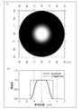
- 6A is a plan view of a lens to which apodization is applied, and FIG.
- FIG. 6B is a transmittance distribution in the radial direction of a lens to which apodization is applied and a lens to which apodization is not applied.
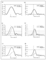
- FIG. 7 shows a two-dimensional plot of a point spread function (PSF) for a lens to which apodization is applied and a lens to which apodization is not applied, and a cross-sectional view of the PSF.
- PSF point spread function
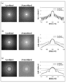
- FIG. 8 shows a modulation transfer function (MTF: Modulus of the Optical Transfer Function) and a spatial frequency (SF: Spatial Frequency) obtained by Fourier transforming a PSF of a lens to which apodization is applied and a lens to which apodization is not applied. It is a graph which shows the relationship.
- MTF Modulus of the Optical Transfer Function
- SF Spatial Frequency
- FIG. 10 is an image of the Landolt ring that would be seen when using a lens to which apodization was applied and a lens to which apodization was not applied.
- the pupil diameter is 2.0 mm
- the pupil diameter is 3.0 mm
- the pupil diameter is 4.0 mm
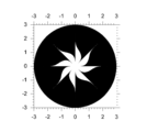
- FIG. 11 is a plan view of the intraocular lens of Example 1 obtained by binarizing the region where the transmittance changes in the radial direction.
- 12A is a PSF of the intraocular lens of Example 1, FIG.
- FIG. 12B is a cross-sectional view of the PSF
- FIG. 12C is an intraocular lens of Example 1 and apodization. This is an image of the Landolt ring that would be seen when using a lens to which the lens is applied and a lens to which the apodization is not applied.
- 13A is a plan view of a lens to which apodization is applied
- FIG. 13B is a transmittance distribution in the radial direction of a lens to which apodization is applied and a lens to which apodization is not applied.
- FIG. 14 shows a two-dimensional plot of a point spread function (PSF) for a lens with and without apodization, and a cross-sectional view of the PSF.
- PSF point spread function
- FIG. 14A the pupil diameter is 2.0 mm
- FIG. 14B the pupil diameter is 3.0 mm
- FIG. 14C the pupil diameter is 4.0 mm.
- FIG. 15 is a plan view of an intraocular lens of Example 2 obtained by binarizing a region where the transmittance changes in the radial direction.
- 16A is a PSF of the intraocular lens of Example 2
- FIG. 16B is a cross-sectional view of the PSF
- FIG. 16C is an intraocular lens of Example 2 and apodization. This is an image of the Landolt ring that would be seen when using a lens to which the lens is applied and a lens to which the apodization is not applied.
- FIG. 1 is a plan view of an intraocular lens according to the present embodiment.
- the intraocular lens 1 has a substantially circular convex lens shape.
- the intraocular lens 1 is made of a soft material such as soft acrylic, silicon, or hydrogel, or a hard material such as polymethyl methacrylate (PMMA).
- PMMA polymethyl methacrylate
- the diameter of the intraocular lens 1 is not particularly limited as long as it is a diameter that can function as an intraocular lens. In the present embodiment, the diameter of the intraocular lens 1 is set to 6.0 mm. Moreover, what is necessary is just to set the thickness of the intraocular lens 1 according to a desired refractive index.
- a supporting arm portion or the like may be attached to the outer peripheral portion of the intraocular lens 1 as necessary.
- the support arm has a role of holding and fixing the intraocular lens in the eye.
- the intraocular lens 1 has a transmission region 2 that is a region through which light incident on the lens is transmitted and a non-transmission region 3 that is a region through which light is not transmitted. That is, the intraocular lens 1 according to the present embodiment is binarized into a transmissive region 2 and a non-transmissive region 3.
- the opaque region 3 is formed, for example, by applying a mask to the lens.
- the transmission region 2 and the non-transmission region 3 are arranged so as to be equivalent to a change in transmittance in the change region when a lens having a region (change region) in which the transmittance changes in the radial direction is assumed. Has been.
- FIG. 2 is a plan view of a lens (hereinafter also referred to as gradation lens 11) having a region where the transmittance varies in the radial direction.
- the gradation lens 11 includes, in order from the optical center O of the lens toward the outer periphery of the lens, a circular region 12 having a radius r1, an annular region 14 having an inner diameter r1 and an outer diameter r2, and an inner diameter r2 and an outer diameter. And an annular region 13 in which r3.
- the circular region 12 is a region that transmits light (transmittance 100%), and the annular region 13 is a region 13 that does not transmit light (transmittance 0%).
- the annular region 14 is a region where the circular region 11 and the annular region 13 are connected, and the transmittance is gradually decreased toward the outer periphery of the lens. Therefore, in the present embodiment, the gradation lens 11 has a region (continuous region) where the transmittance shows a continuous value from the center O to r3, and the change region (annular region 14) is included in the continuous region. .
- a method for obtaining such a gradation lens 11 is not particularly limited, and is a region (annular region 14) in which the transmittance is continuously changed according to desired optical characteristics and the circular region 12 and the annular region 13 are connected. ) May be used.
- the annular region 14 preferably has a distribution that changes so that the transmittance gradually decreases in the direction from the center of the lens toward the outer periphery.
- the gradation lens 11 is obtained by applying apodization to a pinhole lens having an opening with a predetermined diameter.
- the pinhole lens 21 has an opening 22 that transmits light and an annular region 23 that does not transmit light.
- the transmittance is discontinuous at the end of the opening 22, that is, at a point at a distance rc from the center O. Since such a pinhole lens 21 has a diffraction limit, the light transmitted through the opening 22 is diffracted, and concentric fringes are observed. That is, the PSF of the light transmitted through the opening 22 generally includes a side lobe and a side ring. Due to such side lobes and the like, the contrast is lowered in the pinhole lens.
- amplitude apodization is applied to the pinhole lens.
- “apodization” means that discontinuity is removed or smoothed using a mathematical function with respect to the discontinuous transmittance distribution. Specifically, by applying apodization to the pinhole lens 21 shown in FIG. 3, a region where the transmittance gradually decreases from the vicinity of the end of the opening (at the end of the opening) is formed. By softening the sharp change in the transmittance), the transmittance is made continuous in the range from the opening to the outer periphery of the lens. By doing so, a gradation lens 11 as shown in FIG. 2 can be obtained.
- the gradation lens 11 has a region where the transmittance shows a continuous value (continuous region) and a region where the transmittance gradually changes in the radial direction (change region).
- the transmittance shows a continuous value in the radial direction
- the transmittance is expressed by a function f (r) of the diameter r, or can be approximated to f (r).
- f (r) When approaching from the diameter (r ⁇ ) smaller than a certain diameter r toward the diameter r, and approaching from the diameter (r + ⁇ ) larger than the certain diameter r toward the diameter r, both f ( r) has the same value
- the transmittance is discontinuous in the radial direction means that the diameter approaches from the diameter (r ⁇ ) to the diameter r and moves from the diameter (r + ⁇ ) to the diameter r. This means that f (r) does not become the same value when approaching. Specific examples are shown below.
- the transmittance when paying attention to the diameter r1, the transmittance is 1 when approaching r1 from a value smaller than r1, and from the value larger than r1, r1 The transmittance is also 1 when approaching toward. Focusing on the diameter r2, similarly to r1, the transmittance is 0 both when approaching r2 from a value smaller than r2 and when approaching r2 from a value larger than r2. Become. Therefore, in the graph shown in FIG. 2, the transmittance shows a continuous value from 0 to r3.
- the transmittance when paying attention to the diameter rc, the transmittance becomes 1 when approaching rc from a value smaller than rc, and a value larger than rc. When approaching from rc to rc, the transmittance is zero. Therefore, in the graph shown in FIG. 3, the transmittance is discontinuous at rc.
- Mathematical functions used when applying apodization are not particularly limited.
- a function may be selected from known functions according to optical characteristics required for the lens, and examples thereof include a Gaussian function, a sine function, and a cosine function.
- the obtained gradation lens 11 is a lens having a relatively wide viewable range and improved contrast as compared with the pinhole lens 21.
- Patent Documents 6 and 7 employ a method of forming a mask by applying a photosensitive material on a lens and exposing it to light.
- a rotating mask having a petal shape is disposed between a lens and a light source, and a photosensitive material on the lens is partially exposed to form a region where the transmittance varies in the radial direction.
- the lens on which the mask is formed is small and it is extremely difficult to obtain a desired gradation.
- the obtained gradation may vary from lens to lens.
- a lens having optical characteristics equivalent to those of the gradation lens is proposed from a viewpoint completely different from the technical idea of manufacturing the lens by reproducing the transmittance distribution in the gradation lens as it is.
- the lens can be configured only from the transmission region and the non-transmission region. Therefore, it is not necessary to form a gradation that is extremely difficult to reproduce in the lens, and a lens having optical characteristics equivalent to that of the gradation lens can be easily manufactured by simply forming an opaque region on the lens.
- a substantially circular lens in plan view is divided into n pieces in the circumferential direction, and divided into n fan-shaped regions.
- the number (n) to be divided is 2 or more, and preferably 4 or more.
- the lens is divided into four equal parts.
- the sector-shaped region C1 is configured from a region where the transmittance shows a continuous value from the optical center O toward the radial direction, and includes a region 14 (change region) where the transmittance changes in the radial direction. Since the transmittance distribution in each sector region is equal, the transmittance at a point where the distance from the optical center O is r is equal in each sector region.
- a transmission line segment 51 is formed when the angle ⁇ a of the fan-shaped region is 0 to 3 ⁇ / 8 [rad], and not when ⁇ a is 3 ⁇ / 8 to ⁇ / 2 [rad].
- a transmission line segment 52 is formed. If the transmittance is 20% (0.20) at a point where the distance r from the center O is rb, a transmission line segment 51 is formed and the angle ⁇ b is 0 to ⁇ / 10 [rad]. The opaque line segment 52 is formed until ⁇ b is from ⁇ / 10 to ⁇ / 2 [rad].
- a line segment (arc) having a length r ⁇ is converted into a transmission line segment 51 and a non-transmission line segment 52 so as to be equivalent to the transmittance at the diameter r in the change region 14. Allocation. Therefore, in the intraocular lens 1, the transmittance on the circumference having the diameter r is determined by the length ratio of the transmission line segment 51 and the non-transmission line segment 52 in the circumferential direction. By performing such an operation in the radial direction from the center O to the outer periphery r3 of the lens, as shown in FIG. 4, the ratio between the length of the transmission line segment and the length of the non-transmission line segment in the circumferential direction is the radial direction. Thus, regions (14a and 14b) continuously changing are obtained. Since only the region 14a having a transmittance of 100% and the region 14b having a transmittance of 0% exist in this region, this region is binarized.
- the intraocular lens 1 has a transmittance of 100% and a transmittance of 0 at a certain diameter.
- the radial change of the transmittance in the change region 14 of the gradation lens 11 is a change in the radial direction of the length ratio of the transmission line segment 51 and the non-transmission line segment 52 in the circumferential direction in the intraocular lens 1. It corresponds.
- the binarized intraocular lens 1 having optical characteristics equivalent to those of the gradation lens 11 can be obtained.
- the upper limit of the number (n) to be divided is preferably 32 or less.
- the method for producing the binarized intraocular lens is not particularly limited, and may be produced using a known method.
- the above-mentioned non-transparent region is obtained by applying a photosensitive substance to the surface of a lens material obtained by putting a predetermined polymer material into a mold and heat-polymerizing it, and masking and exposing the above-described transmissive region. Can be formed.
- the change region when the change region is binarized, the change region is divided into a region where the transmittance is 100% and a region where the transmittance is 0%.
- the transmittance value is not limited to 100% and 0%, and a region indicating the maximum value of the transmittance required for the lens and a region indicating the minimum value may be formed.
- the line segment (arc) is divided and distributed to the transmission line segment and the non-transmission line segment.
- a minute region is set along the circumferential direction, and the region having the transmittance of 100% is set. You may allocate the area of a micro area
- the gradation lens has a continuous value when transmitting from the center O of the lens toward the outer periphery. That is, the entire lens is composed of a continuous region where the transmittance shows a continuous value.
- a region where the transmittance is discontinuous may be binarized.
- a region where the transmittance is discontinuous may be binarized in the vicinity 70 of the boundary between the region 2 where the transmittance changes and the non-transmissive region 3.
- the lens can be manufactured more easily.
- the region from the center O to the boundary vicinity 70 is a continuous region in which the transmittance shows a continuous value, and the above-described effect can be obtained.
- Example 1 a lens was designed using a virtual model having optical characteristics similar to those of an average human eye, and the optical characteristics of the lens were simulated.
- a Liou-Brennan eye model having the parameters shown in Table 1 was used as a virtual model.
- a model in which a 20.0D spherical intraocular lens is inserted instead of the crystalline lens of the human eye is used.
- the diameter of the intraocular lens was 6.0 mm, and the pupil diameter was 3.0 mm.
- the function I S (r) used for apodization is a function of the lens diameter r, and in this embodiment, a sine function represented by the following formula 1 was used.
- FIG. 6A shows a plan view of a lens (Apodized) to which apodization is applied.
- FIG. 6B shows the transmittance distribution in the radial direction of the lens to which apodization obtained by simulation is applied, together with the transmittance distribution of a lens to which apodization is not applied (Unapodized).
- the lens to which the apodization was not applied naturally had the same transmittance distribution as that of the pinhole lens having an aperture diameter of 3 mm.
- the transmittance is 1 (100%) up to a point where the distance r from the center O is 0.5 mm, and when the distance exceeds 0.5 mm, the transmittance starts to gradually decrease. It was confirmed that the transmittance was 0 (0%) at a point of 1.5 mm, and thereafter the transmittance distribution was 0%.
- a lens to which apodization is applied is composed of a continuous region where the transmittance is a continuous value, and the continuous region includes a region where the transmittance changes in the radial direction (change region). It was.
- the above simulation was also performed when the pupil diameters shown in Table 1 were 2.0 mm and 4.0 mm.
- the results when the pupil diameter is 2.0 mm, 3.0 mm, and 4.0 mm are shown.
- FIG. 7A to 7C show a two-dimensional plot of a point spread function (PSF) regarding a lens to which apodization is applied and a lens to which apodization is not applied, and cross-sectional views of the PSF.
- FIG. 7A shows the result when the pupil diameter is 2.0 mm
- FIG. 7B shows the result when the pupil diameter is 3.0 mm
- FIG. 7C shows the pupil. This is the result when the diameter is 4.0 mm.
- FIG. 8A shows the result when the pupil diameter is 2.0 mm
- FIG. 8B shows the result when the pupil diameter is 3.0 mm
- FIG. 8C shows the pupil. This is the result when the diameter is 4.0 mm.
- MTF is expressed as a function of SF, is an index of image transfer characteristics (resolution), and changes according to changes in SF.
- a large MTF indicates a high contrast.
- SF indicates the number of repeated white and black stripes included in the unit length.
- the visual acuity indicates a minimum visual angle at which a white part and a black part of a visual target can be recognized separately, and is an index of eye resolution. Therefore, it can be said that SF and visual acuity correspond.
- the range of human visual acuity corresponds to the low frequency side SF, and in order to increase the contrast of the image in the range of human visual acuity, the MTF on the lower SF side is higher than the MTF on the higher SF side. Is required to be high. For example, when SF is 100 cycles / mm (corresponding to a visual acuity of 1.0 (20/20)), from FIGS. 8A to 8C, a lens to which apodization is applied has an MTF higher than that of an unapplied lens. It was confirmed that the contrast was improved in the range of human vision. It was also confirmed that the contrast tends to be improved as the pupil diameter increases.
- FIG. 9 shows defocusing when the horizontal axis is defocused and the vertical axis is a specific SF (50 cycles / mm for (a) to (c) and 100 cycles / mm for (d) to (f)).
- the characteristic (Through Focus Response: TFR) is shown.
- 9A and 9D show the results when the pupil diameter was 2.0 mm
- FIGS. 9B and 9E show the results when the pupil diameter was 3.0 mm.
- FIG. ) And (f) are the results of setting the pupil diameter to 4.0 mm.
- a lens to which apodization is applied has a higher contrast and a wider width than an unapplied lens.
- the wide width means that the depth of focus is deep, and that contrast can be obtained even when the focus is deviated to some extent. This width is an indicator of the visible range. Therefore, it can be confirmed that a lens to which apodization is applied has a wider visible range than an unapplied lens.
- FIG. 10 shows an image of the Landolt ring that would be seen when using a lens with and without an apodization applied.
- 10A shows the result of setting the pupil diameter to 2.0 mm
- FIG. 10B shows the result of setting the pupil diameter to 3.0 mm
- FIG. The result is 0 mm.
- the lens (gradation lens) to which the apodization was applied had a wider focus range and a higher contrast range than the unapplied lens, that is, the visible range was wide. .
- the change region of the lens (gradation lens) to which apodization was applied was binarized to obtain a lens according to Example 1.
- the pupil diameter was 4.0 mm.
- the gradation lens is equally divided into n along the circumferential direction, and the transmittance I (x, y) at an arbitrary point (x, y) in the gradation lens is binarized. Convert to I DS (x, y). In this embodiment, IDS is calculated using Equation 2 below.
- Equation 2 “mod (a, b)” indicates a modulo operation and indicates the remainder of “a / b”.
- FIG. 12A shows a PSF of the binarized lens shown in FIG. 11, and FIG. 12B shows a cross-sectional view of the PSF.
- FIG. 12B shows a cross-sectional view of the PSF.
- the cross-section of the PSF of the lens to which the apodization shown in FIG. 7C is not applied is also shown.
- the lens according to Example 1 has a reduced side lobe than the PSF of the lens to which apodization is not applied. It was confirmed that
- FIG. 12 (c) shows the Landolt ring that would be visible when using the binarized lens according to Example 1, a lens to which apodization was applied, and a lens to which apodization was not applied. Show the image.
- the lens according to Example 1 shows better visual acuity characteristics than a lens to which apodization is not applied, and has almost the same visual acuity characteristics as a lens to which apodization is applied. I was able to confirm.
- Example 2 when applying apodization, a Gaussian function I G (r) shown in the following Expression 3 was used instead of the sine function of Example 1.
- the Gaussian function I G (r) is a function of the radius r, and is a function obtained by convolution of the rectangular function (x) shown in Expression 4 and the Gaussian function G (r) shown in Expression 5.
- FIG. 13A shows a plan view of a lens (Apodized) to which apodization is applied. Further, FIG. 13B shows the transmittance distribution in the radial direction of the lens to which the apodization is applied, together with the transmittance distribution of the lens (Unapodized) to which the apodization is not applied.
- FIGS. 14 (a) to (c) a two-dimensional plot of a point spread function (PSF) for a lens to which apodization is applied and a lens to which apodization is not applied, and cross-sectional views of the PSF are shown in FIGS. 14 (a) to (c).
- 14A shows the result when the pupil diameter is 2.0 mm
- FIG. 14B shows the result when the pupil diameter is 3.0 mm
- FIG. 14C shows the result when the pupil diameter is 4. mm. The result is 0 mm.
- Example 1 As is clear from FIGS. 13 and 14, it was confirmed that the same result as in Example 1 was obtained even when the function used when applying the apodization was changed.
- the change region of the lens (gradation lens) to which apodization was applied was binarized using the equations shown in Equations 3 to 5 above, and the lens according to Example 2 was obtained. Binarization was performed in the same manner as in Example 1 except that the following Equation 6 was used when binarizing. That is, the pupil diameter was set to 4.0 mm. The results are shown in FIG.
- Example 2 From FIG. 15, as in Example 1, it was confirmed that the region where the transmittance varies in the radial direction was binarized, and the lens according to Example 2 was composed of a transmissive region and a non-transmissive region. . In Example 2 of FIG. 15, binarization was performed so that the transmission region was asymmetric.
- FIG. 16A shows a point spread function (PSF) of the binarized lens shown in FIG. 15, and FIG. 16B shows a cross-sectional view of the PSF.
- PSF point spread function
- FIG. 16B shows a cross-sectional view of the PSF.
- the cross-section of the PSF of the lens to which the apodization shown in FIG. 7C is not applied is also shown. Similar to Example 1, even when binarized, it was confirmed that the side lobe of the lens according to Example 2 was reduced more than the PSF of the lens to which apodization was not applied.
- FIG. 16 (c) shows the Landolt ring that would be seen when using a binarized lens according to Example 2, a lens to which apodization was applied, and a lens to which apodization was not applied. Show the image.
- the lens according to Example 2 shows better visual acuity characteristics than a lens to which apodization is not applied, and has almost the same visual acuity characteristics as a lens to which apodization is applied. It was.
Landscapes
- Health & Medical Sciences (AREA)
- Ophthalmology & Optometry (AREA)
- Physics & Mathematics (AREA)
- General Health & Medical Sciences (AREA)
- General Physics & Mathematics (AREA)
- Optics & Photonics (AREA)
- Transplantation (AREA)
- Oral & Maxillofacial Surgery (AREA)
- Cardiology (AREA)
- Engineering & Computer Science (AREA)
- Biomedical Technology (AREA)
- Heart & Thoracic Surgery (AREA)
- Vascular Medicine (AREA)
- Life Sciences & Earth Sciences (AREA)
- Animal Behavior & Ethology (AREA)
- Public Health (AREA)
- Veterinary Medicine (AREA)
- Prostheses (AREA)
- Eyeglasses (AREA)
Abstract
光が透過する透過領域と、光が透過しない不透過領域と、を備える眼用レンズであって、レンズの中心から径方向に向かって光の透過率が連続値を示す領域であって、少なくともレンズの中心を含む連続領域と、連続領域において光の透過率が径方向に変化している変化領域と、を備えるレンズを想定した場合、眼用レンズにおいて、眼用レンズの中心から径方向に向かって、円周方向における透過領域および不透過領域の存在割合が、想定したレンズの変化領域における透過率の変化と等価となるように、透過領域および不透過領域が配置されていることを特徴とする眼用レンズである。
Description
本発明は、眼用レンズ、眼用レンズの設計方法および眼用レンズの製造方法に関する。
眼用レンズは、コンタクトレンズ、眼内レンズ等が知られており、視力矯正、白内障手術後のレンズ等として用いられている。
眼用レンズの一例としての眼内レンズは、白内障の進行により濁った水晶体を手術により除去した後、水晶体の機能を代替させるために眼内に挿入される。眼内レンズに求められる機能には様々あり、たとえば、より鮮明に物体を見ることを可能にすること(コントラストを高くすること)、見える範囲(明視域)を広くすること等が挙げられる。このような要求に対し、レンズ部に関する様々な光学設計が提案されている。
コントラストを高める技術としては、たとえば、特許文献1~3に記載されている技術が知られている。これらの技術は、レンズの球面収差を低減することにより、コントラストを改善している。しかしながら、球面収差を低減すると、レンズの焦点深度が浅くなるため、球面レンズに比べて見える範囲が狭くなるという問題があった。
一方、見える範囲を広くする技術としては、多焦点眼内レンズが知られている。たとえば、特許文献4には、所望の見え方に応じて近用部と遠用部とを配置する眼内レンズが記載されている。しかしながら、近用部および遠用部のそれぞれに入る光量は、レンズ全体で光を捉える球面レンズの場合よりも少なくなり、結果として、コントラストが低下するという問題があった。また、特許文献5には、焦点深度をより深くすることにより、見える範囲を球面レンズの場合よりも広くした眼内レンズが記載されている。しかしながら、この眼内レンズも、特許文献4と同様に、球面レンズに比べてコントラストが低下してしまう。
上述したように、コントラストを高める機能と見える範囲を広くする機能とは、一般的に相反する機能であるため、これらの機能を適度に両立する技術が知られている。たとえば、特許文献6および7には、レンズの中心部から径方向に透過率が徐々に変化するように設計された光学部を有する環状マスクレンズが記載されている。
上記の光学部を有する環状マスクレンズでは、コントラストがある程度改善され、見える範囲が比較的広く確保されている。一方、特許文献6および7では、この環状マスクレンズを製造する際に、その素材であるレンズに光を照射しレンズ上の感光物質を感光させることで、光が透過しない領域(環状マスク)を形成することが記載されている。このとき、「花弁」形状を有する回転マスクをレンズと光源との間に配置し、これを回転させている。このようにすることで、回転マスクの「花弁」形状部分は、光源から発せられた光を部分的に透過させるため、レンズ上の感光物質は部分的に感光される。その結果、透過率が徐々に変化する領域が形成されることになる。
しかしながら、透過率が徐々に変化する領域を形成するには回転マスクの回転数、露光強度等を精密に制御する必要があることに加え、マスクが形成されるレンズが小さく、実際には、このような領域を有するレンズを製造することは極めて困難であった。
本発明は、上記の問題を鑑みてなされ、見える範囲が比較的広く、コントラストが改善され、しかも容易に製造可能な眼用レンズ、眼用レンズの設計方法および製造方法を提供することを、主たる目的とする。
本発明者は、上記の課題を解決すべく、透過率が変化する領域のように製造が困難な領域を形成することなく、製造が容易でありながら、透過率が変化する領域と等価な領域を形成することにより、上記の課題を解決できることを見出し、本発明を完成させるに至った。
すなわち、本発明の態様は、
光が透過する透過領域と、光が透過しない不透過領域と、を備える眼用レンズであって、
レンズの中心から径方向に向かって光の透過率が連続値を示す領域であって、少なくともレンズの中心を含む連続領域と、前記連続領域において光の透過率が径方向に変化している変化領域と、を備えるレンズを想定した場合、
前記眼用レンズにおいて、前記眼用レンズの中心から径方向に向かって、円周方向における前記透過領域および不透過領域の存在割合が、想定したレンズの前記変化領域における透過率の変化と等価となるように、前記透過領域および不透過領域が配置されていることを特徴とする眼用レンズである。
光が透過する透過領域と、光が透過しない不透過領域と、を備える眼用レンズであって、
レンズの中心から径方向に向かって光の透過率が連続値を示す領域であって、少なくともレンズの中心を含む連続領域と、前記連続領域において光の透過率が径方向に変化している変化領域と、を備えるレンズを想定した場合、
前記眼用レンズにおいて、前記眼用レンズの中心から径方向に向かって、円周方向における前記透過領域および不透過領域の存在割合が、想定したレンズの前記変化領域における透過率の変化と等価となるように、前記透過領域および不透過領域が配置されていることを特徴とする眼用レンズである。
本発明によれば、見える範囲が比較的広く、コントラストが改善され、しかも容易に製造可能な眼用レンズ、眼用レンズの設計方法および製造方法を提供することができる。
以下、本発明を、図面に示す実施形態に基づき、眼用レンズの一例としての眼内レンズについて以下の順序で詳細に説明する。
1.眼内レンズの構成
2.眼内レンズの設計方法
3.実施形態の効果
4.変形例
1.眼内レンズの構成
2.眼内レンズの設計方法
3.実施形態の効果
4.変形例
(1.眼内レンズの構成)
図1は本実施形態に係る眼内レンズの平面図である。眼内レンズ1は、略円形の凸レンズ形状を有している。また、眼内レンズ1は、軟質アクリル、シリコン、ハイドロゲル等の軟質材料、あるいは、ポリメチルメタクリレート(PMMA)等の硬質材料から構成される。眼内レンズ1の直径は、眼内レンズとしての機能を発揮できる程度の径であれば特に制限されない。本実施形態では、眼内レンズ1の直径は6.0mmに設定される。また、眼内レンズ1の厚みは、所望の屈折率等に合わせて設定すればよい。
図1は本実施形態に係る眼内レンズの平面図である。眼内レンズ1は、略円形の凸レンズ形状を有している。また、眼内レンズ1は、軟質アクリル、シリコン、ハイドロゲル等の軟質材料、あるいは、ポリメチルメタクリレート(PMMA)等の硬質材料から構成される。眼内レンズ1の直径は、眼内レンズとしての機能を発揮できる程度の径であれば特に制限されない。本実施形態では、眼内レンズ1の直径は6.0mmに設定される。また、眼内レンズ1の厚みは、所望の屈折率等に合わせて設定すればよい。
図1には図示していないが、眼内レンズ1の外周部分には、必要に応じて支持腕部等が取り付けられていてもよい。支持腕部は、眼内において眼内レンズを保持・固定する役割を有する。
眼内レンズ1は、レンズに入射する光が透過する領域である透過領域2と、光が透過しない領域である不透過領域3と、を有している。すなわち、本実施形態に係る眼内レンズ1は、透過領域2と不透過領域3とに二値化されている。不透過領域3は、たとえば、レンズにマスクを施すことにより形成されている。この透過領域2と不透過領域3とは、透過率が径方向に変化している領域(変化領域)を有するレンズを想定した場合、当該変化領域における透過率の変化と等価となるように配置されている。
(2.眼内レンズの設計方法)
以下では、想定したレンズにおける透過率が径方向に変化している領域と等価になるように、透過領域2と不透過領域3とを配置する手法について述べるが、まず、透過率が径方向に変化する領域(変化領域)を有するレンズの光学特性について詳細に説明する。
以下では、想定したレンズにおける透過率が径方向に変化している領域と等価になるように、透過領域2と不透過領域3とを配置する手法について述べるが、まず、透過率が径方向に変化する領域(変化領域)を有するレンズの光学特性について詳細に説明する。
図2は、透過率が径方向に変化する領域を有するレンズ(以下、グラデーションレンズ11ともいう)の平面図である。グラデーションレンズ11は、レンズの光学中心Oからレンズの外周に向かう方向に、順に、半径r1の円領域12と、内径がr1で外径がr2である環状領域14と、内径がr2で外径がr3である環状領域13と、を有している。円領域12は光が透過する領域(透過率100%)であり、環状領域13は光が透過しない領域13(透過率0%)である。環状領域14は、円領域11と環状領域13とを接続し、レンズの外周方向に向かうにつれ透過率が漸次低下している領域である。したがって、本実施形態では、グラデーションレンズ11は、中心Oからr3まで透過率が連続値を示す領域(連続領域)を有しており、変化領域(環状領域14)は連続領域に含まれている。
このようなグラデーションレンズ11を得る方法としては特に制限されず、所望の光学特性に応じて、透過率を連続的に変化させ、かつ円領域12と環状領域13とを接続する領域(環状領域14)を形成する方法であればよい。眼内レンズの場合には、図2に示すように、環状領域14は、レンズの中心から外周に向かう方向に透過率が漸次低下するように変化する分布を有していることが好ましい。本実施形態では、所定の径の開口部を有するピンホールレンズにアポダイゼーションを適用することによりグラデーションレンズ11を得る。
図3に示すように、ピンホールレンズ21は光を透過する開口部22と、光を透過しない環状領域23を有している。当該ピンホールレンズ21において、開口部22の端部、すなわち、中心Oから距離rcの地点で透過率は不連続となっている。このようなピンホールレンズ21は、回折限界を有しているため、開口部22を透過した光は回折し、同心円状の縞が観察される。すなわち、開口部22を透過した光のPSFは一般的にサイドローブ(side lobe)およびサイドリング(side ring)を含んでいる。このようなサイドローブ等に起因して、ピンホールレンズでは、コントラストが低下してしまう。
そこで、サイドローブ等を低減するために、ピンホールレンズに対して振幅アポダイゼーション(amplitude apodization)を適用する。本実施形態では、「アポダイゼーション」とは、不連続な透過率の分布に対し、数学的関数を用いて不連続性を除去するあるいはスムージングすることを意味する。具体的には、図3に示すピンホールレンズ21に対して、アポダイゼーションを適用することにより、開口部の端部付近から徐々に透過率が減少する領域を形成して(開口部の端部における透過率の急峻な変化をやわらげて)、開口部からレンズの外周にわたる範囲において透過率に連続性を持たせる。このようにすることにより、図2に示すようなグラデーションレンズ11を得ることができる。このグラデーションレンズ11は、透過率が連続値を示す領域(連続領域)と、透過率が径方向に徐々に変化する領域(変化領域)と、を有している。
なお、本明細書において、「径方向に透過率が連続値を示す」とは、透過率が径rの関数f(r)で表される場合、または、f(r)に近似できる場合に、ある径rよりもαだけ小さい径(r-α)から径rに向かって近づき、ある径rよりもαだけ大きい径(r+α)から径rに向かって近づいたときに、どちらもf(r)が同じ値になることを意味し、「径方向に透過率が不連続である」とは、径(r-α)から径rに向かって近づき、径(r+α)から径rに向かって近づいたときに、f(r)が同じ値にならないことを意味する。以下に具体例を示す。
図2に示す半径距離と透過率との関係を示すグラフにおいて、径r1に着目すると、r1よりも小さい値からr1に向かって近づいたときには、透過率は1となり、r1よりも大きい値からr1に向かって近づいたときにも透過率は1になる。また、径r2に着目すると、r1と同様に、r2よりも小さい値からr2に向かって近づいたときにも、r2よりも大きい値からr2に向かって近づいたときにも、透過率は0となる。したがって、図2に示すグラフにおいて、透過率はrが0~r3まで連続値を示している。
一方、図3に示す半径距離と透過率との関係を示すグラフでは、径rcに着目すると、rcよりも小さい値からrcに向かって近づいたときには、透過率は1となり、rcよりも大きい値からrcに向かって近づいたときには、透過率は0となる。したがって、図3に示すグラフにおいて、透過率はrcにおいて不連続である。
アポダイゼーションを適用する際に用いる数学的関数は特に制限されない。公知の関数から、レンズに要求される光学特性に応じて関数を選択すればよく、たとえば、ガウシアン関数、正弦関数、余弦関数等が挙げられる。
得られるグラデーションレンズ11は、ピンホールレンズ21に比較して、見える範囲が比較的広く、コントラストが改善されたレンズである。しかしながら、上述したように、グラデーションレンズを製造することは非常に難しい。たとえば、特許文献6および7では、レンズ上に感光物質を塗布し、これを感光させることでマスクを形成する方法を採用している。この方法において、花弁形状を有する回転マスクをレンズと光源との間に配置し、レンズ上の感光物質を部分的に露光して透過率が径方向に変化する領域を形成している。しかしながら、グラデーションを正確に再現するには回転マスクの回転数、露光強度等を精密に制御する必要があることに加え、マスクが形成されるレンズが小さく、所望のグラデーションを得ることは極めて難しい。また、得られるグラデーションがレンズごとにばらつくこともありえる。
そこで、本実施形態では、グラデーションレンズにおける透過率の分布をそのまま再現してレンズを製造するという技術的思想とは全く異なる観点から、グラデーションレンズと同等の光学特性を有するレンズを提案している。すなわち、グラデーションレンズにおける透過率が径方向に変化する領域を二値化することにより、レンズを透過領域および不透過領域のみから構成することができる。したがって、極めて再現が難しいグラデーションをレンズに形成する必要はなく、レンズ上に不透過領域を形成するだけでグラデーションレンズと同等の光学特性を有するレンズを容易に製造することができる。
透過率が径方向に変化する領域を二値化する方法としては、たとえば、以下に示す方法が挙げられる。まず、平面視で略円形のレンズを円周方向にn分割して、n個の扇形の領域に分割する。分割する数(n)としては、2以上であり、4以上が好ましい。図4ではレンズを4等分している。扇形の領域C1は、光学中心Oから径方向に向かって透過率が連続値を示す領域から構成されており、かつ透過率が径方向に変化する領域14(変化領域)を含んでいる。各扇形領域における透過率の分布は等しいため、光学中心Oからの距離がrである地点における透過率は各扇形領域において等しい。
図4に示すように、扇形領域C1において、中心Oからの距離rがraである点において透過率が75%(0.75)とすると、径がraである点の集合(円弧)のうち、3/4の個数の点が、透過率が100%を示す点であり、1/4の個数の点が、透過率が0%を示す点であると仮定する。そして、透過率が100%を示す点の集合である透過線分51と、透過率が0%を示す点の集合である不透過線分52とを形成するように、これらの点を円弧上に配分すればよい。
具体的には、図4では、扇形の領域の角度θaが0~3π/8[rad]までは、透過線分51が形成され、θaが3π/8~π/2[rad]までは不透過線分52が形成される。また、中心Oからの距離rがrbである点において透過率が20%(0.20)とすると、角度θbが0~π/10[rad]までは、透過線分51が形成され、角度θbがπ/10~π/2[rad]までは不透過線分52が形成される。
すなわち、二値化する際には、長さがrθの線分(円弧)を、変化領域14における径rにおける透過率と等価となるように、透過線分51と不透過線分52とに配分している。したがって、眼内レンズ1において、径がrである円周上の透過率は、円周方向における透過線分51と不透過線分52との長さ割合によって決まる。このような操作を径方向に中心Oからレンズの外周r3まで行うことで、図4に示すように、円周方向における透過線分の長さと不透過線分の長さとの割合が、径方向に連続的に変化している領域(14aおよび14b)が得られる。この領域には、透過率が100%の領域14aおよび透過率が0%の領域14bのみが存在しているため、この領域は二値化されていることになる。
換言すれば、径方向に透過率が変化している領域(変化領域)を有するグラデーションレンズ11を想定した場合、眼内レンズ1において、ある径における透過率を、透過率100%と透過率0%とに分けた割合として表すことにより、変化領域14における透過率の変化と等価となるように二値化することができる。したがって、グラデーションレンズ11の変化領域14における透過率の径方向の変化は、眼内レンズ1において、円周方向における透過線分51と不透過線分52との長さ割合の径方向の変化に対応している。
以上より、グラデーションレンズ11と同等の光学特性を有する二値化された眼内レンズ1を得ることができる。
なお、レンズを分割する数(n)が大きすぎる場合、扇形の領域の中心角θが小さくなるため、円弧の長さrθが小さくなり、配分される透過線分の長さおよび不透過線分の長さも短くなってしまう。その結果、レンズ全体における透過線分および不透過線分の分布がグラデーションに近くなってしまう。この場合には、レンズの製造が困難となるため好ましくない。したがって、本実施形態では、製造上の観点から、分割する数(n)の上限は32以下であることが好ましい。
このようにして二値化された眼内レンズを製造する方法としては、特に制限されず、公知の方法を用いて製造すればよい。たとえば、所定の高分子材料を成形型に投入し、加熱重合させて得られるレンズ素材の表面に感光性物質を塗布し、上述した透過領域をマスクして露光することにより、上述した不透過領域を形成することができる。
(3.本実施形態の効果)
本実施形態によれば、径方向に透過率が変化する領域(変化領域)を有するレンズ(グラデーションレンズ)を想定した場合に、当該領域における透過率の変化と等価になるように、二値化された(透過領域と不透過領域とが形成された)レンズが得られる。このようなレンズは、グラデーションレンズとは異なり、レンズの光学面が透過領域および不透過領域のみで構成されているため、容易に製造できる。しかも、本実施形態に係るレンズは、変化領域における透過率の変化と等価となるように二値化されているため、グラデーションレンズと同等の光学特性を有している。したがって、見える範囲が比較的広く、コントラストが改善された眼用レンズを得ることができる。
本実施形態によれば、径方向に透過率が変化する領域(変化領域)を有するレンズ(グラデーションレンズ)を想定した場合に、当該領域における透過率の変化と等価になるように、二値化された(透過領域と不透過領域とが形成された)レンズが得られる。このようなレンズは、グラデーションレンズとは異なり、レンズの光学面が透過領域および不透過領域のみで構成されているため、容易に製造できる。しかも、本実施形態に係るレンズは、変化領域における透過率の変化と等価となるように二値化されているため、グラデーションレンズと同等の光学特性を有している。したがって、見える範囲が比較的広く、コントラストが改善された眼用レンズを得ることができる。
(4.変形例)
上記の実施形態では、変化領域を二値化する際に、透過率が100%を示す領域と、透過率が0%を示す領域とに分けている。しかしながら、透過率の値は、100%と0%とに制限されず、レンズに要求される透過率の最大値を示す領域と、最小値を示す領域と、を形成してもよい。
上記の実施形態では、変化領域を二値化する際に、透過率が100%を示す領域と、透過率が0%を示す領域とに分けている。しかしながら、透過率の値は、100%と0%とに制限されず、レンズに要求される透過率の最大値を示す領域と、最小値を示す領域と、を形成してもよい。
上記の実施形態では、線分(円弧)を分割して透過線分と不透過線分とに配分しているが、円周方向に沿って微小領域を設定し、透過率100%の領域の面積と透過率0%の領域の面積とが、透過率の変化と等価になるように、微小領域の面積を配分してもよい。このとき、径方向の距離rに応じて、設定する微小領域の面積を変化させてもよい。
上記の実施形態では、グラデーションレンズは、レンズの中心Oから外周に向かう際の透過率が連続値を示している。すなわち、レンズ全体が、透過率が連続値を示す連続領域から構成されている。
しかしながら、レンズにおいて視力特性にあまり影響を与えない部分であれば、透過率が不連続な領域が二値化されていてもよい。たとえば、図5に示すように、透過率が変化している領域2と不透過領域3との境界近傍70において、透過率が不連続な領域が二値化されていてもよい。境界近傍のシャープな部分を丸める場合には、レンズの製造がより容易になる。この場合であっても、中心Oから境界近傍70までの領域は透過率が連続値を示す連続領域であり、上述した効果が得られる。
以下、本発明を、さらに詳細な実施例に基づき説明するが、本発明は、これら実施例に限定されない。
(実施例1)
実施例1では、人間の平均的な眼と同様の光学特性を有する仮想モデルを用いてレンズを設計し、レンズの光学特性のシミュレーションを行った。仮想モデルとして、表1に示すパラメータを有するLiou-Brennan眼モデルを用いた。本実施例では、人間の眼の水晶体の代わりに20.0Dの球面眼内レンズを挿入したモデルとした。眼内レンズの径は6.0mmとし、瞳孔径を3.0mmとした。
実施例1では、人間の平均的な眼と同様の光学特性を有する仮想モデルを用いてレンズを設計し、レンズの光学特性のシミュレーションを行った。仮想モデルとして、表1に示すパラメータを有するLiou-Brennan眼モデルを用いた。本実施例では、人間の眼の水晶体の代わりに20.0Dの球面眼内レンズを挿入したモデルとした。眼内レンズの径は6.0mmとし、瞳孔径を3.0mmとした。

また、シミュレーションはZEMAX Development Corporation社製のZEMAX(登録商標)光学設計プログラムを用いて評価した。アポダイゼーションおよび二値化に関する計算はZEMAXからMATLAB(登録商標)に波面データ等の必要なデータを送りMATLABにて計算を行った。
まず、開口部の径が3mmであり、その外側は不透過領域である眼内レンズに対して、正弦関数を用いたアポダイゼーションを適用するシミュレーションを行った。アポダイゼーションに用いる関数IS(r)は、レンズ径rの関数であり、本実施例では、下記の式1に示す正弦関数を用いた。

式1における「a」および「b」は、アポダイゼーションの始点および終点の位置をそれぞれ示している。本実施例では、aは0.5mm、bは1.5mmとした。アポダイゼーションを適用したレンズ(Apodized)の平面図を図6(a)に示す。また、シミュレーションにより得られるアポダイゼーションを適用したレンズの径方向における透過率の分布を、アポダイゼーションが適用されていないレンズ(Unapodized)の透過率の分布とともに図6(b)に示す。
図6(b)より、アポダイゼーションが適用されていないレンズは、当然、開口部の径が3mmのピンホールレンズと同じ透過率分布を有していた。一方、アポダイゼーションが適用されたレンズでは、中心Oからの距離rが0.5mmの地点までは透過率が1(100%)であり、0.5mmを超えると、透過率が漸次低下し始め、1.5mmの地点で透過率が0(0%)となり、それ以降は透過率が0%となる透過率分布を有していることが確認できた。すなわち、アポダイゼーションを適用したレンズは、レンズ全体が、透過率が連続値を示す連続領域から構成されており、連続領域には、透過率が径方向に変化する領域(変化領域)が含まれていた。
また、本実施例では、表1に示す瞳孔径を、2.0mmおよび4.0mmにした場合にも上記のシミュレーションを行った。以下では、瞳孔径を2.0mm、3.0mm、4.0mmとした場合の結果を示す。
アポダイゼーションを適用したレンズおよびアポダイゼーションを適用していないレンズに関する点広がり関数(PSF)の2次元プロット、および当該PSFの断面図を、図7(a)~(c)に示す。図7(a)は、瞳孔径を2.0mmとした場合の結果であり、図7(b)は、瞳孔径を3.0mmとした場合の結果であり、図7(c)は、瞳孔径を4.0mmとした場合の結果である。
図7(a)~(c)から明らかなように、アポダイゼーションを適用することで、規格化半径が大きくなるほど、サイドローブが低減されていることが確認できた。また、瞳孔径が大きくなるほど、サイドローブが低減される傾向にあることが確認できた。したがって、アポダイゼーションを適用していないレンズでは、コントラストが低下しているのに対し、アポダイゼーションを適用したレンズでは、コントラストが高くなっていることが確認できた。
続いて、アポダイゼーションを適用したレンズおよびアポダイゼーションを適用していないレンズに関して、それぞれのPSFをフーリエ変換することによりMTFを計算した。結果を図8に示す。図8(a)は、瞳孔径を2.0mmとした場合の結果であり、図8(b)は、瞳孔径を3.0mmとした場合の結果であり、図8(c)は、瞳孔径を4.0mmとした場合の結果である。
MTFは、SFの関数として表され、像の伝達特性(解像度)の指標であり、SFの変化に応じて変化する。MTFが大きい場合、コントラストが高いことを示す。また、SFは単位長さに含まれる白と黒との縞模様の繰り返しの数を示している。ここで、視力は視標の白い部分と黒い部分とを分離して認識できる最小視角を示しており、眼の解像度の指標である。したがって、SFと視力とは対応しているということができる。
図8(a)~(c)より、アポダイゼーションを適用することで、SFが低い側のMTFが強められ、SFが高い側のMTFが弱められることが確認できた。人間の視力の範囲は低周波数側のSFに対応しており、人間の視力の範囲において像のコントラストを高めるには、SFが高い側のMTFを高くすることよりも、SFが低い側のMTFを高くすることが求められる。たとえば、SFが100cycle/mmである場合(視力1.0(20/20)に相当)、図8(a)~(c)より、アポダイゼーションを適用したレンズは、未適用のレンズよりもMTFが大きくなっている、すなわち、人間の視力の範囲において、コントラストが改善されていることが確認できた。また、瞳孔径が大きくなるほど、コントラストがより改善される傾向にあることが確認できた。
図9は、横軸にデフォーカス、縦軸に特定のSF((a)~(c)は50cycle/mm、(d)~(f)は100cycle/mm)におけるMTFとした場合に、デフォーカス特性(Through Focus Response:TFR)を示している。図9(a)および(d)は、瞳孔径を2.0mmとした結果であり、図9(b)および(e)は、瞳孔径を3.0mmとした結果であり、図9(c)および(f)は、瞳孔径を4.0mmとした結果である。
図9から明らかなように、アポダイゼーションを適用したレンズは、未適用のレンズよりも、コントラストが高く、その幅が広い。幅が広いということは、焦点深度が深く、ある程度焦点がずれてもコントラストが得られることを意味しており、この幅は見える範囲の指標となるものである。したがって、アポダイゼーションを適用したレンズは、未適用のレンズよりも見える範囲が広がっていることが確認できる。
図7~9より、アポダイゼーションを適用することにより、収差の抑制、焦点深度の深さ等の種々の光学特性が未適用のレンズよりも改善していることが確認できた。これらの結果を視覚的に示すために、図10にアポダイゼーションを適用したレンズと未適用のレンズとをそれぞれ用いた際に見えるであろうランドルト環の像を示す。図10(a)は、瞳孔径を2.0mmとした結果であり、図10(b)は、瞳孔径を3.0mmとした結果であり、図10(c)は、瞳孔径を4.0mmとした結果である。
図10から明らかなように、アポダイゼーションを適用したレンズ(グラデーションレンズ)は、未適用のレンズよりも焦点が合う範囲が広く、コントラストが高い範囲が広い、すなわち、見える範囲が広いことが確認できた。
続いて、アポダイゼーションを適用したレンズ(グラデーションレンズ)の変化領域を二値化して実施例1に係るレンズを得た。瞳孔径を4.0mmとした。具体的には、グラデーションレンズを、円周方向に沿ってn等分し、グラデーションレンズ内の任意の点(x,y)における透過率I(x,y)を、二値化された透過率IDS(x,y)に変換する。本実施例では、IDSは以下の式2を用いて計算される。

式2において、「mod(a,b)」は、モジュロ演算を示しており、「a/b」の余りを示している。また、nは正の整数で表される離散化数であり、本実施形態ではレンズ領域を分割する数を示している。本実施例ではnを8とした。なお、レンズを分割して得られる扇形領域の中心角の角度をθとすると、xおよびyは、x=rcosθ、y=rsinθと表すことができる。また、tan-1(y/x)は、点(x、y)の角度θを示す。結果を図11に示す。
図11より、透過率が径方向に変化する領域(変化領域)が二値化され、実施例1に係るレンズは透過領域および不透過領域のみから構成されていることが確認できた。なお、本実施例では、透過領域が線対称となるように二値化を行った。
次に、図11に示す二値化されたレンズのPSFを図12(a)に、当該PSFの断面図を図12(b)に示す。図12(b)の断面図では、参考のために図7(c)に示すアポダイゼーションが未適用のレンズのPSFの断面も併せて示している。図12(a)および(b)から明らかなように、二値化した場合であっても、実施例1に係るレンズは、アポダイゼーションを適用していないレンズのPSFよりもサイドローブが低減されていることが確認できた。
また、図12(c)に、実施例1に係る二値化したレンズと、アポダイゼーションを適用したレンズと、アポダイゼーションを適用していないレンズと、をそれぞれ用いた際に見えるであろうランドルト環の像を示す。図12(c)から明らかなように、実施例1に係るレンズは、アポダイゼーションを適用していないレンズよりも良好な視力特性を示し、アポダイゼーションを適用したレンズとほぼ同等の視力特性を示していることが確認できた。
(実施例2)
実施例2では、アポダイゼーションを適用する際に、実施例1の正弦関数の代わりに、下記の式3に示すガウシアン関数IG(r)を用いた。このガウシアン関数IG(r)は、半径rの関数であり、式4に示す矩形関数(x)と式5に示すガウシアン関数G(r)との畳み込みにより得られる関数である。



実施例2では、アポダイゼーションを適用する際に、実施例1の正弦関数の代わりに、下記の式3に示すガウシアン関数IG(r)を用いた。このガウシアン関数IG(r)は、半径rの関数であり、式4に示す矩形関数(x)と式5に示すガウシアン関数G(r)との畳み込みにより得られる関数である。
式3において、「c」は、透過率が0.5(50%)となる半径値である。本実施例では、cは1.0mmとした。また、式(5)におけるガウシアン関数の標準偏差σは0.32とした。アポダイゼーションを適用したレンズ(Apodized)の平面図を図13(a)に示す。また、アポダイゼーションを適用したレンズの径方向における透過率の分布を、アポダイゼーションを適用していないレンズ(Unapodized)の透過率の分布とともに図13(b)に示す。
さらに、アポダイゼーションを適用したレンズおよびアポダイゼーションを適用していないレンズに関する点広がり関数(PSF)の2次元プロット、および当該PSFの断面図を、図14(a)~(c)に示す。図14(a)は、瞳孔径を2.0mmとした結果であり、図14(b)は、瞳孔径を3.0mmとした結果であり、図14(c)は、瞳孔径を4.0mmとした結果である。
図13および14から明らかなように、アポダイゼーションを適用する際に用いる関数を変更した場合であっても、実施例1と同様の結果が得られていることが確認できた。
続いて、上記の式3~5に示される式を用いてアポダイゼーションを適用したレンズ(グラデーションレンズ)の変化領域を二値化して実施例2に係るレンズを得た。二値化する際に下記の式6を用いた以外は、実施例1と同様に二値化を行った。すなわち、瞳孔径を4.0mmとした。結果を図15に示す。

図15より、実施例1と同様に、透過率が径方向に変化する領域が二値化され、実施例2に係るレンズは透過領域と不透過領域とから構成されていることが確認できた。なお、図15の実施例2では、透過領域が非対称となるように二値化を行った。
次に、図15に示す二値化されたレンズの点広がり関数(PSF)を図16(a)に、当該PSFの断面図を図16(b)に示す。図16(b)の断面図では、参考のために図7(c)に示すアポダイゼーションを適用していないレンズのPSFの断面も併せて示している。実施例1と同様に、二値化した場合であっても、実施例2に係るレンズは、アポダイゼーションを適用していないレンズのPSFよりもサイドローブが低減されていることが確認できた。
また、図16(c)に、実施例2に係る二値化したレンズと、アポダイゼーションを適用したレンズと、アポダイゼーションを適用していないレンズと、をそれぞれ用いた際に見えるであろうランドルト環の像を示す。実施例1と同様に、実施例2に係るレンズは、アポダイゼーションを適用していないレンズよりも良好な視力特性を示し、アポダイゼーションを適用したレンズとほぼ同等の視力特性を示していることが確認できた。
1…眼内レンズ
2…透過領域
3…不透過領域
2…透過領域
3…不透過領域
Claims (5)
- 光が透過する透過領域と、光が透過しない不透過領域と、を備える眼用レンズであって、
レンズの中心から径方向に向かって光の透過率が連続値を示す領域であって、少なくともレンズの中心を含む連続領域と、前記連続領域において光の透過率が径方向に変化している変化領域と、を備えるレンズを想定した場合、
前記眼用レンズにおいて、前記眼用レンズの中心から径方向に向かって、円周方向における前記透過領域および不透過領域の存在割合が、想定したレンズの前記変化領域における透過率の変化と等価となるように、前記透過領域および不透過領域が配置されていることを特徴とする眼用レンズ。 - 前記眼用レンズにおいて、同一半径上にある点の集合から構成される線分を円周方向にn分割し、分割された前記線分の円周方向の長さを、前記想定されたレンズの前記変化領域における当該同一半径上の透過率と等価となるように、光が透過する透過線分の長さと、光が透過しない不透過線分の長さと、を配分することにより、前記透過領域および不透過領域が配置されることを特徴とする請求項1に記載の眼用レンズ。
ただし、nは2以上の整数である。 - 前記変化領域は、レンズの中心から径方向に光の透過率が不連続に変化する部分を有する領域に振幅アポダイゼーションを適用することにより得られる領域である請求項1または2に記載の眼用レンズ。
- レンズの中心から径方向に向かって光の透過率が変化している変化領域を二値化することにより、光が透過する透過領域と、光が透過しない不透過領域と、を眼用レンズに設定する工程を有することを特徴とする眼用レンズの設計方法。
- レンズの中心から径方向に向かって光の透過率が変化している変化領域を二値化することにより、光が透過する透過領域と、光が透過しない不透過領域と、を眼用レンズに設定するデータに基づき、前記眼用レンズを製造する工程を有することを特徴とする眼用レンズの製造方法。
Applications Claiming Priority (2)
| Application Number | Priority Date | Filing Date | Title |
|---|---|---|---|
| JP2013-061486 | 2013-03-25 | ||
| JP2013061486A JP6190133B2 (ja) | 2013-03-25 | 2013-03-25 | 眼用レンズの設計方法および眼用レンズの製造方法 |
Publications (1)
| Publication Number | Publication Date |
|---|---|
| WO2014156607A1 true WO2014156607A1 (ja) | 2014-10-02 |
Family
ID=51623590
Family Applications (1)
| Application Number | Title | Priority Date | Filing Date |
|---|---|---|---|
| PCT/JP2014/056287 Ceased WO2014156607A1 (ja) | 2013-03-25 | 2014-03-11 | 眼用レンズ、眼用レンズの設計方法および眼用レンズの製造方法 |
Country Status (2)
| Country | Link |
|---|---|
| JP (1) | JP6190133B2 (ja) |
| WO (1) | WO2014156607A1 (ja) |
Cited By (4)
| Publication number | Priority date | Publication date | Assignee | Title |
|---|---|---|---|---|
| US9195074B2 (en) | 2012-04-05 | 2015-11-24 | Brien Holden Vision Institute | Lenses, devices and methods for ocular refractive error |
| US9201250B2 (en) | 2012-10-17 | 2015-12-01 | Brien Holden Vision Institute | Lenses, devices, methods and systems for refractive error |
| US9541773B2 (en) | 2012-10-17 | 2017-01-10 | Brien Holden Vision Institute | Lenses, devices, methods and systems for refractive error |
| US10838234B2 (en) | 2016-08-18 | 2020-11-17 | Johnson & Johnson Vision Care, Inc. | Contact lens with improved visual performance and minimized halo utilizing pupil apodization |
Families Citing this family (1)
| Publication number | Priority date | Publication date | Assignee | Title |
|---|---|---|---|---|
| JP6500484B2 (ja) * | 2015-02-19 | 2019-04-17 | 株式会社ニデック | 多焦点眼内レンズ |
Citations (4)
| Publication number | Priority date | Publication date | Assignee | Title |
|---|---|---|---|---|
| US4955904A (en) * | 1989-08-21 | 1990-09-11 | The Beth Israel Hospital Association | Masked intraocular lens and method for treating a patient with cataracts |
| US5260727A (en) * | 1990-10-22 | 1993-11-09 | Oksman Henry C | Wide depth of focus intraocular and contact lenses |
| JP2011177599A (ja) * | 2008-09-30 | 2011-09-15 | Yoichi Mikawa | 眼内レンズ |
| JP5369273B1 (ja) * | 2012-02-20 | 2013-12-18 | 株式会社メニコンネクト | 着色コンタクトレンズ |
Family Cites Families (1)
| Publication number | Priority date | Publication date | Assignee | Title |
|---|---|---|---|---|
| US7628810B2 (en) * | 2003-05-28 | 2009-12-08 | Acufocus, Inc. | Mask configured to maintain nutrient transport without producing visible diffraction patterns |
-
2013
- 2013-03-25 JP JP2013061486A patent/JP6190133B2/ja active Active
-
2014
- 2014-03-11 WO PCT/JP2014/056287 patent/WO2014156607A1/ja not_active Ceased
Patent Citations (4)
| Publication number | Priority date | Publication date | Assignee | Title |
|---|---|---|---|---|
| US4955904A (en) * | 1989-08-21 | 1990-09-11 | The Beth Israel Hospital Association | Masked intraocular lens and method for treating a patient with cataracts |
| US5260727A (en) * | 1990-10-22 | 1993-11-09 | Oksman Henry C | Wide depth of focus intraocular and contact lenses |
| JP2011177599A (ja) * | 2008-09-30 | 2011-09-15 | Yoichi Mikawa | 眼内レンズ |
| JP5369273B1 (ja) * | 2012-02-20 | 2013-12-18 | 株式会社メニコンネクト | 着色コンタクトレンズ |
Cited By (22)
| Publication number | Priority date | Publication date | Assignee | Title |
|---|---|---|---|---|
| US10838235B2 (en) | 2012-04-05 | 2020-11-17 | Brien Holden Vision Institute Limited | Lenses, devices, and methods for ocular refractive error |
| US12298605B2 (en) | 2012-04-05 | 2025-05-13 | Brien Holden Vision Institute Limited | Lenses, devices, methods and systems for refractive error |
| US9535263B2 (en) | 2012-04-05 | 2017-01-03 | Brien Holden Vision Institute | Lenses, devices, methods and systems for refractive error |
| US11809024B2 (en) | 2012-04-05 | 2023-11-07 | Brien Holden Vision Institute Limited | Lenses, devices, methods and systems for refractive error |
| US9575334B2 (en) | 2012-04-05 | 2017-02-21 | Brien Holden Vision Institute | Lenses, devices and methods of ocular refractive error |
| US11644688B2 (en) | 2012-04-05 | 2023-05-09 | Brien Holden Vision Institute Limited | Lenses, devices and methods for ocular refractive error |
| US10203522B2 (en) | 2012-04-05 | 2019-02-12 | Brien Holden Vision Institute | Lenses, devices, methods and systems for refractive error |
| US10209535B2 (en) | 2012-04-05 | 2019-02-19 | Brien Holden Vision Institute | Lenses, devices and methods for ocular refractive error |
| US10466507B2 (en) | 2012-04-05 | 2019-11-05 | Brien Holden Vision Institute Limited | Lenses, devices and methods for ocular refractive error |
| US9195074B2 (en) | 2012-04-05 | 2015-11-24 | Brien Holden Vision Institute | Lenses, devices and methods for ocular refractive error |
| US10948743B2 (en) | 2012-04-05 | 2021-03-16 | Brien Holden Vision Institute Limited | Lenses, devices, methods and systems for refractive error |
| US11320672B2 (en) | 2012-10-07 | 2022-05-03 | Brien Holden Vision Institute Limited | Lenses, devices, systems and methods for refractive error |
| US10534198B2 (en) | 2012-10-17 | 2020-01-14 | Brien Holden Vision Institute Limited | Lenses, devices, methods and systems for refractive error |
| US10520754B2 (en) | 2012-10-17 | 2019-12-31 | Brien Holden Vision Institute Limited | Lenses, devices, systems and methods for refractive error |
| US11333903B2 (en) | 2012-10-17 | 2022-05-17 | Brien Holden Vision Institute Limited | Lenses, devices, methods and systems for refractive error |
| US9759930B2 (en) | 2012-10-17 | 2017-09-12 | Brien Holden Vision Institute | Lenses, devices, systems and methods for refractive error |
| US9541773B2 (en) | 2012-10-17 | 2017-01-10 | Brien Holden Vision Institute | Lenses, devices, methods and systems for refractive error |
| US9201250B2 (en) | 2012-10-17 | 2015-12-01 | Brien Holden Vision Institute | Lenses, devices, methods and systems for refractive error |
| US12298604B2 (en) | 2012-10-17 | 2025-05-13 | Brien Holden Vision Institute Limited | Lenses, devices, methods and systems for refractive error |
| US12360398B2 (en) | 2012-10-17 | 2025-07-15 | Brien Holden Vision Institute Limited | Lenses, devices, systems and methods for refractive error |
| US10838234B2 (en) | 2016-08-18 | 2020-11-17 | Johnson & Johnson Vision Care, Inc. | Contact lens with improved visual performance and minimized halo utilizing pupil apodization |
| US11686954B2 (en) | 2016-08-18 | 2023-06-27 | Johnson & Johnson Vision Care, Inc. | Contact lens with improved visual performance and minimized halo utilizing pupil apodization |
Also Published As
| Publication number | Publication date |
|---|---|
| JP2014184022A (ja) | 2014-10-02 |
| JP6190133B2 (ja) | 2017-08-30 |
Similar Documents
| Publication | Publication Date | Title |
|---|---|---|
| JP2023052663A (ja) | 眼科多焦点回折レンズ | |
| KR101436300B1 (ko) | 확장된 초점 심도를 갖는 안구내 렌즈 | |
| JP6190133B2 (ja) | 眼用レンズの設計方法および眼用レンズの製造方法 | |
| CN112004499B (zh) | 多焦点人工眼科镜片以及生产多焦点人工眼科镜片的方法 | |
| JP4551489B2 (ja) | 回折レンズの製造方法 | |
| JP5824076B2 (ja) | 回折型多焦点眼用レンズとその製造方法 | |
| JP5993950B2 (ja) | 回折型多焦点眼用レンズとその製造方法 | |
| JP7442228B2 (ja) | 新世代眼科多焦点レンズ | |
| US11934043B2 (en) | Myopia control lens and related methods | |
| WO2016035055A1 (en) | Wide depth of focus vortex intraocular lenses and associated methods | |
| TWI842031B (zh) | 用於應用至眼鏡或其他眼用的鏡片之具有漸變折射率元件的薄膜 | |
| JP2010104772A (ja) | 眼内レンズ | |
| TWI845079B (zh) | 隱形眼鏡及關於其之方法 | |
| KR20230165770A (ko) | 나선형 트렉을 따라 굴절능 수정을 배치하는 동공 크기에 맞게 제조된 초점 성능을 가진 안구 내 렌즈 | |
| KR102678511B1 (ko) | 안과 렌즈 제조 방법 | |
| KR102794105B1 (ko) | 비대칭 구배 지수 광학 요소를 포함하는 안과용 렌즈의 제조 방법 | |
| NL2008054C2 (en) | A trifocal intraocular lens. | |
| CA3172792C (en) | Myopia control lens and related methods | |
| EP4560365A1 (en) | Multifocal lens having central axicon portion | |
| WO2024144489A1 (en) | A quadrifocal diffractive ocular lens | |
| HK40109262B (zh) | 制造包含非对称梯度折射率光学元件的眼科镜片的方法 | |
| HK40109262A (zh) | 制造包含非对称梯度折射率光学元件的眼科镜片的方法 | |
| HK40095631A (zh) | 制造眼科镜片的方法 | |
| HK40095631B (zh) | 制造眼科镜片的方法 |
Legal Events
| Date | Code | Title | Description |
|---|---|---|---|
| 121 | Ep: the epo has been informed by wipo that ep was designated in this application |
Ref document number: 14772743 Country of ref document: EP Kind code of ref document: A1 |
|
| NENP | Non-entry into the national phase |
Ref country code: DE |
|
| 122 | Ep: pct application non-entry in european phase |
Ref document number: 14772743 Country of ref document: EP Kind code of ref document: A1 |