WO2014156493A1 - Fluorescence observation device - Google Patents
Fluorescence observation device Download PDFInfo
- Publication number
- WO2014156493A1 WO2014156493A1 PCT/JP2014/055321 JP2014055321W WO2014156493A1 WO 2014156493 A1 WO2014156493 A1 WO 2014156493A1 JP 2014055321 W JP2014055321 W JP 2014055321W WO 2014156493 A1 WO2014156493 A1 WO 2014156493A1
- Authority
- WO
- WIPO (PCT)
- Prior art keywords
- image
- fluorescence
- white light
- color component
- component
- Prior art date
Links
Images


Classifications
-
- A—HUMAN NECESSITIES
- A61—MEDICAL OR VETERINARY SCIENCE; HYGIENE
- A61B—DIAGNOSIS; SURGERY; IDENTIFICATION
- A61B1/00—Instruments for performing medical examinations of the interior of cavities or tubes of the body by visual or photographical inspection, e.g. endoscopes; Illuminating arrangements therefor
- A61B1/00002—Operational features of endoscopes
- A61B1/00004—Operational features of endoscopes characterised by electronic signal processing
- A61B1/00009—Operational features of endoscopes characterised by electronic signal processing of image signals during a use of endoscope
- A61B1/000094—Operational features of endoscopes characterised by electronic signal processing of image signals during a use of endoscope extracting biological structures
-
- A—HUMAN NECESSITIES
- A61—MEDICAL OR VETERINARY SCIENCE; HYGIENE
- A61B—DIAGNOSIS; SURGERY; IDENTIFICATION
- A61B1/00—Instruments for performing medical examinations of the interior of cavities or tubes of the body by visual or photographical inspection, e.g. endoscopes; Illuminating arrangements therefor
- A61B1/00002—Operational features of endoscopes
- A61B1/00043—Operational features of endoscopes provided with output arrangements
- A61B1/00045—Display arrangement
- A61B1/0005—Display arrangement combining images e.g. side-by-side, superimposed or tiled
-
- A—HUMAN NECESSITIES
- A61—MEDICAL OR VETERINARY SCIENCE; HYGIENE
- A61B—DIAGNOSIS; SURGERY; IDENTIFICATION
- A61B1/00—Instruments for performing medical examinations of the interior of cavities or tubes of the body by visual or photographical inspection, e.g. endoscopes; Illuminating arrangements therefor
- A61B1/04—Instruments for performing medical examinations of the interior of cavities or tubes of the body by visual or photographical inspection, e.g. endoscopes; Illuminating arrangements therefor combined with photographic or television appliances
- A61B1/043—Instruments for performing medical examinations of the interior of cavities or tubes of the body by visual or photographical inspection, e.g. endoscopes; Illuminating arrangements therefor combined with photographic or television appliances for fluorescence imaging
-
- A—HUMAN NECESSITIES
- A61—MEDICAL OR VETERINARY SCIENCE; HYGIENE
- A61B—DIAGNOSIS; SURGERY; IDENTIFICATION
- A61B5/00—Measuring for diagnostic purposes; Identification of persons
- A61B5/0059—Measuring for diagnostic purposes; Identification of persons using light, e.g. diagnosis by transillumination, diascopy, fluorescence
- A61B5/0071—Measuring for diagnostic purposes; Identification of persons using light, e.g. diagnosis by transillumination, diascopy, fluorescence by measuring fluorescence emission
-
- G—PHYSICS
- G02—OPTICS
- G02B—OPTICAL ELEMENTS, SYSTEMS OR APPARATUS
- G02B23/00—Telescopes, e.g. binoculars; Periscopes; Instruments for viewing the inside of hollow bodies; Viewfinders; Optical aiming or sighting devices
- G02B23/24—Instruments or systems for viewing the inside of hollow bodies, e.g. fibrescopes
- G02B23/2407—Optical details
- G02B23/2461—Illumination
- G02B23/2469—Illumination using optical fibres
-
- G—PHYSICS
- G02—OPTICS
- G02B—OPTICAL ELEMENTS, SYSTEMS OR APPARATUS
- G02B23/00—Telescopes, e.g. binoculars; Periscopes; Instruments for viewing the inside of hollow bodies; Viewfinders; Optical aiming or sighting devices
- G02B23/24—Instruments or systems for viewing the inside of hollow bodies, e.g. fibrescopes
- G02B23/2476—Non-optical details, e.g. housings, mountings, supports
- G02B23/2484—Arrangements in relation to a camera or imaging device
-
- G—PHYSICS
- G06—COMPUTING; CALCULATING OR COUNTING
- G06T—IMAGE DATA PROCESSING OR GENERATION, IN GENERAL
- G06T5/00—Image enhancement or restoration
- G06T5/50—Image enhancement or restoration by the use of more than one image, e.g. averaging, subtraction
-
- A—HUMAN NECESSITIES
- A61—MEDICAL OR VETERINARY SCIENCE; HYGIENE
- A61B—DIAGNOSIS; SURGERY; IDENTIFICATION
- A61B1/00—Instruments for performing medical examinations of the interior of cavities or tubes of the body by visual or photographical inspection, e.g. endoscopes; Illuminating arrangements therefor
- A61B1/06—Instruments for performing medical examinations of the interior of cavities or tubes of the body by visual or photographical inspection, e.g. endoscopes; Illuminating arrangements therefor with illuminating arrangements
- A61B1/0638—Instruments for performing medical examinations of the interior of cavities or tubes of the body by visual or photographical inspection, e.g. endoscopes; Illuminating arrangements therefor with illuminating arrangements providing two or more wavelengths
-
- G—PHYSICS
- G06—COMPUTING; CALCULATING OR COUNTING
- G06T—IMAGE DATA PROCESSING OR GENERATION, IN GENERAL
- G06T2207/00—Indexing scheme for image analysis or image enhancement
- G06T2207/10—Image acquisition modality
- G06T2207/10024—Color image
-
- G—PHYSICS
- G06—COMPUTING; CALCULATING OR COUNTING
- G06T—IMAGE DATA PROCESSING OR GENERATION, IN GENERAL
- G06T2207/00—Indexing scheme for image analysis or image enhancement
- G06T2207/10—Image acquisition modality
- G06T2207/10064—Fluorescence image
-
- G—PHYSICS
- G06—COMPUTING; CALCULATING OR COUNTING
- G06T—IMAGE DATA PROCESSING OR GENERATION, IN GENERAL
- G06T2207/00—Indexing scheme for image analysis or image enhancement
- G06T2207/20—Special algorithmic details
- G06T2207/20212—Image combination
- G06T2207/20221—Image fusion; Image merging
-
- G—PHYSICS
- G06—COMPUTING; CALCULATING OR COUNTING
- G06T—IMAGE DATA PROCESSING OR GENERATION, IN GENERAL
- G06T2207/00—Indexing scheme for image analysis or image enhancement
- G06T2207/30—Subject of image; Context of image processing
- G06T2207/30004—Biomedical image processing
Definitions
- the present invention relates to a fluorescence observation apparatus.
- Patent Document 1 discloses that a fluorescent region is made red, green, or blue by assigning a gradation value of a fluorescent image to any one of a red component image, a green component image, and a blue component image constituting a color white light image. The area is displayed on the white light image.
- the white light image includes information on the original gradation value, that is, information on the tissue form, and thus there is an advantage that the form of the tissue can also be observed.
- the white light image includes information on the original gradation value, that is, information on the tissue form, and thus there is an advantage that the form of the tissue can also be observed.
- Patent Document 2 a fluorescent region in a white light image is filled with a pseudo color. In this case, the visibility of the fluorescent region is improved, but there is an inconvenience that the observation of the form of the tissue using the white light image is hindered.
- the present invention has been made in view of the above-described circumstances, and is capable of always displaying a fluorescent region in a fluorescent image on a white light image with high visibility without disturbing observation of the form of the subject.
- An object is to provide an observation apparatus.
- the present invention includes a light source that irradiates a subject with white light and excitation light, a fluorescence image generation unit that captures fluorescence generated in the subject by irradiation of the excitation light from the light source, and generates a fluorescence image;
- a white light image generation unit that captures a return light returning from the subject by irradiation of the white light from a light source to generate a color white light image, and each of a plurality of color component images constituting the white light image
- a composition unit that combines the weights set by the setting unit, the condition setting unit sets weights based on the color component image of the white light image, and the fluorescence image is added
- Color component image Weights are the other so as to be larger than the weight for the color component images
- a white light image obtained by photographing a form of a subject by irradiating white light from a light source is acquired by the white light image generating unit, and fluorescence from a lesion part of the subject is photographed by irradiating excitation light from the light source.
- the fluorescence image thus obtained is acquired by the fluorescence image generation unit.
- a combined image in which the lesion part is displayed as the fluorescent region on the white light image is combined.
- a composite image is generated from the color component image with the weight set by the condition setting unit based on the color component of the white light image. That is, the color component image to which the fluorescent image is added is given a higher weight, and the other color component images are given a lower weight, so that the display color component of the fluorescent region in the composite image is changed to another color. Emphasized against ingredients.
- the composite image includes the gradation value in the white light image, that is, information on the form of the subject at the position where the fluorescent region is displayed, the form of the lesioned part can be observed.
- the condition setting unit increases the weight of the color component image to which the fluorescent image is added and / or increases the gradation value of the other color component image in the white light image.
- the weights of the other color component images may be set small.
- the condition setting unit sets the weight based on the gradation value of the fluorescent image in addition to the color component image of the white light image, and the larger the gradation value of the fluorescent image,
- the weight of the color component image to which the fluorescent image is added may be set large and / or the weight of the other color component image may be set small.
- the combining unit may apply the weight only to a region having a gradation value equal to or greater than a predetermined threshold in the fluorescent image. By doing so, it is possible to remove weak fluorescence and noise from the fluorescent image, selectively extract a lesion, and display it as a fluorescent region on the composite image. In other regions, a white light image that accurately represents the color of the subject can be displayed as it is.
- a fluorescence image analysis unit that calculates an average value of gradation values of the fluorescence image and a standard deviation of the gradation values is provided, and the condition setting unit is calculated by the fluorescence image analysis unit.
- the predetermined threshold may be set based on the sum of the average value of the gradation values and the standard deviation. By doing so, the predetermined threshold value fluctuates with the fluctuation of the overall brightness of the fluorescent image, so that the lesioned part can be accurately extracted as a fluorescent region and displayed on the composite image.
- a fluorescence image correction unit that corrects a gradation value of the fluorescence image by dividing the fluorescence image by the white light image, and the fluorescence image analysis unit is corrected by the fluorescence image correction unit.
- the average value and the standard deviation may be calculated using a fluorescent image. In this way, a change in the gradation value of the fluorescent image depending on the observation distance and the observation angle is removed, and a fluorescent image that more accurately reflects the original intensity of the fluorescence generated in the subject can be obtained. By using this corrected fluorescence image, a more accurate average value and standard deviation can be calculated.
- the image processing apparatus includes a fluorescence image correction unit that corrects a gradation value of the fluorescence image by dividing the fluorescence image by the white light image, and the combining unit and the condition setting unit include the fluorescence image correction unit.
- the fluorescent image corrected by the above may be used as the fluorescent image. By doing in this way, it is possible to display a region where fluorescence is emitted in the subject and a fluorescence region reflecting the intensity of the fluorescence more accurately in the composite image.
- the above-described invention may include an enhancement component determination unit that selects a color component image to which the fluorescent image is added according to the color component image of the white light image. By doing in this way, an emphasis component can be selected and determined more appropriately according to the color component of the white light image, and the visibility of the fluorescent region in the composite image can be improved.
- the fluorescent region in the fluorescent image can be always displayed on the white light image with high visibility without disturbing the observation of the form of the subject.
- FIG. 1 is an overall configuration diagram of a fluorescence observation apparatus according to a first embodiment of the present invention. It is a flowchart explaining the process of the image processing unit of FIG. It is a whole block diagram of the fluorescence observation apparatus which concerns on the 2nd Embodiment of this invention. It is a flowchart explaining the process of the image processing unit of FIG. It is a figure which shows an example of the display of the display part of the fluorescence observation apparatus of FIG. It is a whole block diagram of the fluorescence observation apparatus which concerns on the 3rd Embodiment of this invention. It is a flowchart explaining the process of the image processing unit of FIG. It is a whole block diagram of the fluorescence observation apparatus which concerns on the 4th Embodiment of this invention.
- a fluorescence observation apparatus 1 which concerns on the 1st Embodiment of this invention is demonstrated with reference to FIG. 1 and FIG.
- a fluorescence observation apparatus 1 according to this embodiment is an endoscope apparatus, and as shown in FIG.
- an elongated insertion portion 2 inserted into a body a light source 3, excitation light from the light source 3, and An illumination unit 4 that emits white light (reference light) from the distal end 2a of the insertion unit 2 toward the subject X, and an imaging unit 5 that is provided at the distal end 2a of the insertion unit 2 and acquires image information S1 and S2 of the subject X
- An image processing unit 6 that is disposed on the proximal end side of the insertion unit 2 and processes the image information S1 and S2 acquired by the imaging unit 5, and a display unit that displays the image G3 processed by the image processing unit 6 7.
- the light source 3 includes a xenon lamp 31, a filter 32 that extracts excitation light and white light from the light emitted from the xenon lamp 31, and a coupling lens 33 that collects the excitation light and white light extracted by the filter 32. It has.
- the filter 32 selectively transmits light having a wavelength band of 400 nm to 740 nm corresponding to excitation light and white light. That is, in this embodiment, near infrared light (for example, wavelength band 700 nm to 740 nm) is used as excitation light.
- the illumination unit 4 includes a light guide fiber 41 disposed over almost the entire length of the insertion portion 2 in the longitudinal direction, and an illumination optical system 42 provided at the distal end 2a of the insertion portion 2.
- the light guide fiber 41 guides the excitation light and white light collected by the coupling lens 33.
- the illumination optical system 42 diffuses the excitation light and white light guided by the light guide fiber 41 and irradiates the subject X facing the distal end 2 a of the insertion portion 2.
- the imaging unit 5 includes an objective lens 51 that condenses light from the subject X, and white light that reflects excitation light and fluorescence out of the light collected by the objective lens 51 and has a shorter wavelength than the excitation light.
- a dichroic mirror 52 that transmits (wavelength band 400 nm to 700 nm, return light), and two condensing lenses 53 and 54 that condense fluorescence reflected by the dichroic mirror 52 and white light transmitted through the dichroic mirror 52, respectively.
- An image sensor 55 such as a color CCD that captures white light collected by the condenser lens 54, and an image sensor such as a high-sensitivity monochrome CCD or color CMOS that captures the fluorescence condensed by the condenser lens 53. 56.
- reference numeral 57 denotes an excitation light cut filter that selectively transmits fluorescence (for example, a wavelength band of 760 nm to 850 nm) out of the light reflected by the dichroic mirror 52 and blocks excitation light.
- fluorescence for example, a wavelength band of 760 nm to 850 nm
- a special image sensor that can obtain higher sensitivity, for example, an EMCCD (Electron Double CCD) or an ICCD (Image Intensifier CCD) may be used.
- EMCCD Electro Double CCD
- ICCD Image Intensifier CCD
- high-sensitivity imaging may be realized by performing a binning process in which gradation values of a plurality of pixels are added in an element using a monochrome CCD.
- an antibody against CEA (Carcinoembryonic Antigen) is used as the fluorescent dye Cy7 (GE Healthcare).
- a white light image G1 and a fluorescence image G2, which will be described later, can be simultaneously acquired by administering and observing the drug (Anti-CEA-Cy7) labeled with the above to the subject X.
- CEA is known as a protein that is specifically expressed in cancer. Thereby, a cancer lesion part can be acquired as the fluorescence image G2.
- the image processing unit 6 generates a white light image generation unit 61 that generates a white light image G1 from the white light image information S1 acquired by the image sensor 55, and a fluorescent image G2 from the fluorescent image information S2 acquired by the image sensor 56.
- the condition setting unit 63 for setting the weight for each color component image constituting the white light image G1, and the fluorescent image G2 to any one of the color component images of the white light image G1.
- a combining unit 64 that generates a combined image G3.
- the following expression (1) generalizes and represents the relationship between the three color component images constituting the white light image G1 and the three color component images constituting the composite image G3.
- x and y represent coordinates corresponding to the positions of the white light image G1 and the fluorescent image G2 on the image.
- each variable is a value set for each coordinate (x, y), but in order to avoid complication of the equation, (x, y ) Is omitted.
- R (x, y) and F (x, y) are simply expressed as R and F.
- the display color of the fluorescent region Y in the composite image G3 is preferably green. Accordingly, weighting is performed such that the G component image of the white light image G1 corresponding to the fluorescent region Y is enhanced, and the green contrast is enhanced between the fluorescent region Y and the other regions in the composite image G3.
- an image is generated. Therefore, in the following, a case where the composite image G3 in which the G component of the white light image G1 corresponding to the fluorescent region Y is emphasized will be described as an example.
- the gradation value of each pixel of the fluorescence image G2 is compared with a threshold S G, the fluorescent region Y having a larger tone value F than the threshold value S G, added to the G component image of the white-light image G1 To do.
- the gradation value F of each pixel of the fluorescent image G2 is compared with the threshold values S R and S B, and the threshold values S R and S B It is preferable to extract a region having a larger gradation value F and to apply a negative weight to the extracted region. This weight is determined by coefficients r, g, b and threshold values S R , S G , S B , and these coefficients and threshold values are set by the condition setting unit 63.
- the synthesized images G3 are generated by synthesizing the obtained images.
- the combining unit 64 and the condition setting unit 63 perform processing using the coefficients r, g, b and threshold values S R , S G , S B set by the following equation (2). That is, the condition setting unit 63 sets the threshold values S R and S B to be smaller as the R component and the B component are larger. Thereby, the composition unit 64 generates a composite image G3 using the R component image and the B component image in which the gradation value is partially reduced in the substantially same region as the fluorescent region Y.
- Equation (2) the dynamic range of each image G1, G2, G3 is assumed to be 12 bits, that is, each gradation value R, G, B, R ′, G ′, B ′, F is
- the thresholds S R and S B are represented by numerical values from 0 to 4095, and vary between 1000 and 2000 depending on the gradation value R or B.
- the fluorescence observation apparatus 1 configured as described above.
- a fluorescent substance that accumulates in the lesioned part Z is administered to the subject X in advance.
- the insertion portion 2 is inserted into the body, the tip 2a thereof is disposed opposite the subject X, and the subject X is irradiated with excitation light and white light from the tip 2a of the insertion portion 2 by the operation of the light source 3.
- the fluorescent substance contained in the lesion Z is excited by excitation light, and fluorescence is emitted, and white light is reflected on the surface of the subject X. Part of the fluorescence emitted from the subject X and the reflected white light returns to the distal end 2 a of the insertion portion 2 and is collected by the objective lens 51.
- FIG. 2 shows a flowchart for explaining image processing by the image processing unit 6.
- the white light image information S1 is input to the white light image generation unit 61 to generate the white light image G1
- the fluorescence image information S2 is input to the fluorescence image generation unit 62 to generate the fluorescence image G2.
- the white light image G1 is sent to the condition setting unit 63 and the condition setting unit 63
- the fluorescent image G2 is sent to the synthesis unit 64.
- step S3 by fluorescence region Y having a gradation value equal to or larger than a predetermined threshold value S G of the fluorescence image G2 is assigned to the G component image of the white-light image G1, the fluorescence region Y is displayed in green A composite image G3 is generated (step S3), and the generated composite image G3 is displayed on the display unit 7 (step S4).
- threshold values S R and S B are set based on the color component of each pixel of the white light image G1 (step S2), and the set threshold values S R and S B are input to the combining unit 64. Sent.
- the synthesizer 64 the R component image and the B component image of the white light image G1 are extracted from regions that are substantially the same as the fluorescent region Y based on the threshold values S R and S B , and the color components and gradations of the extracted region are extracted. A negative weight based on the value F is applied and the gradation value is reduced before being used to generate the composite image G3.
- the redness and blueness of the subject X serving as the background are stronger, so that the redness and blueness are more strongly suppressed.
- the display color green is emphasized relative to red and blue.
- the fluorescent region Y showing the lesioned part Z can always be displayed in clear green that is easy to visually recognize.
- red which is a complementary color of green
- green can be effectively emphasized.
- the white light image G1 in which the information on the color and form of the subject X is accurately reproduced can be displayed as it is.
- the threshold values S R and S B are changed depending on the color component of the white light image G1, but instead, for example, as shown in the following equation (3):
- the coefficients r and b may be varied depending on the color components of the white light image G1. Even in this case, the same effect can be obtained by adjusting the magnitude of the negative weight attached to the R component image and the B component image.
- the expressions (2) and (3) may be combined, and both the threshold values S R and S B and the coefficients r and b may be changed simultaneously. Further, in the present embodiment, the description has been made assuming that the dynamic range of the gradation value is 12 bits. However, the present invention is not limited to this, and the same processing can be performed even in the case of 8 bits or 16 bits, for example. That is, in the above formulas (2) and (3), instead of the constant 4095, 255 may be used for 8 bits and 65535 for 16 bits.
- the G component gradation value of the white light image G1 increases, and the R component and G component gradation values decrease, thereby enhancing the G component.
- An image G3 is obtained.
- the gradation values of the R component and the B component in the composite image G3 reflect the gradation values of the R component and the B component in the white light image G1, information on the form of the subject X is also included in the composite image G3. Remains.
- the G component has a higher gradation value than the R component and the B component, and therefore the visibility of the emphasized G component is superior compared to (A) and (B). .
- the R component of the composite image G3 has a lower gradation value than that of (A) and the B component of the composite image G3 becomes zero, information on the B component of the white light image G1 is lost. Therefore, the information amount of the form of the subject X reflected in the composite image G3 is inferior to (A).
- the values of the threshold values S R , S G , and S B are appropriately changed according to the color components of the white light image G1 (A), the values of the threshold values S R , S G , and S B are always Compared to the fixed cases (B) and (C), in the synthesized image G3, the visibility of the G component reflecting the information of the fluorescent image G2 is ensured, and the information on the form of the subject X is as much as possible. A more appropriate image that remains can be presented.
- Other embodiments and modifications described below have the same effects as those described in this embodiment. In the above calculation, all values after the decimal point are rounded down.
- the coefficients r and b are negative numbers, but the coefficients r and b may be positive or zero as long as they satisfy the relationship g> r, g. Good. Even if it does in this way, the same effect can be acquired.
- condition setting unit 63 replaces the negative weights for the R component image and the B component image depending on the color components of the white light image G1, instead of setting the positive weights for the G component image. Is set depending on the color component of the white light image G1.
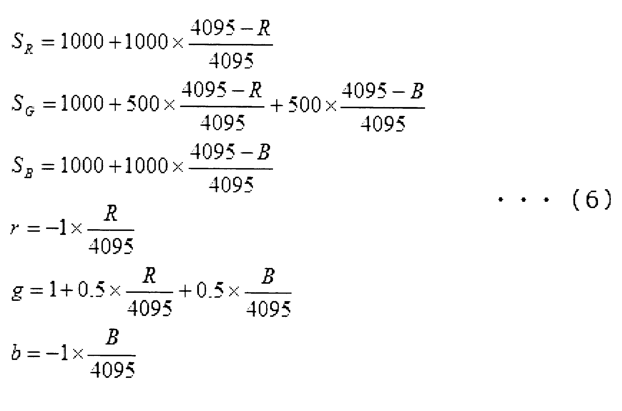
- the condition setting unit 63 as shown in the following formula (4), as the gradation value of the R component and the B component is larger in the white-light image G1, setting a small threshold value S G.
- the gradation value added as the fluorescent region Y to the white light image G1 can be increased, and the green color of the fluorescent region Y can be emphasized in the composite image G3.
- the gradation values of the R component and the B component are reduced as the gradation value F increases, so that the green color of the fluorescent region Y is further effective. Can be emphasized.
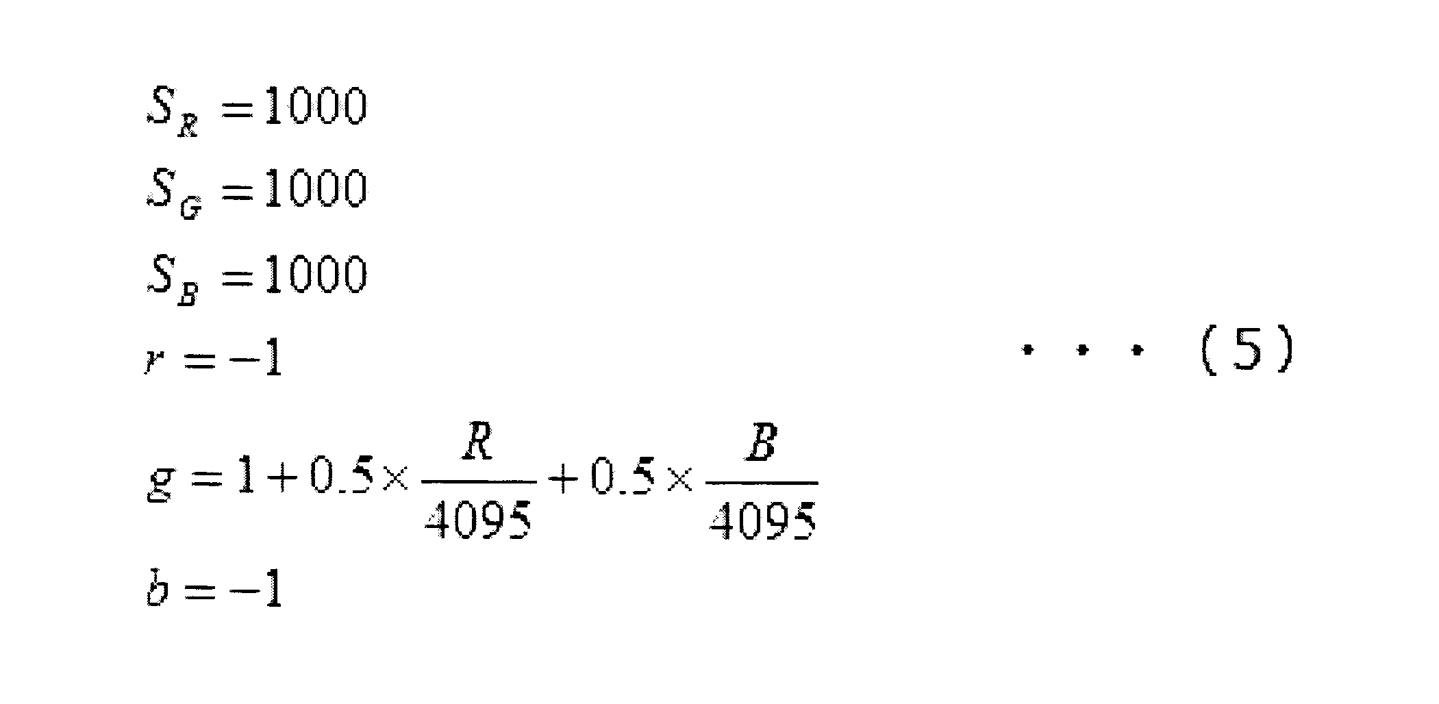
- the coefficient g may be changed depending on the color component of the white light image G1, as shown in the following expression (5), instead of the expression (4).
- the expressions (2), (3), (4) and (5) may be arbitrarily combined.
- the coefficients r, g, and b and the threshold values S R , S G , and S B may be simultaneously changed depending on the color components of the white light image G1.
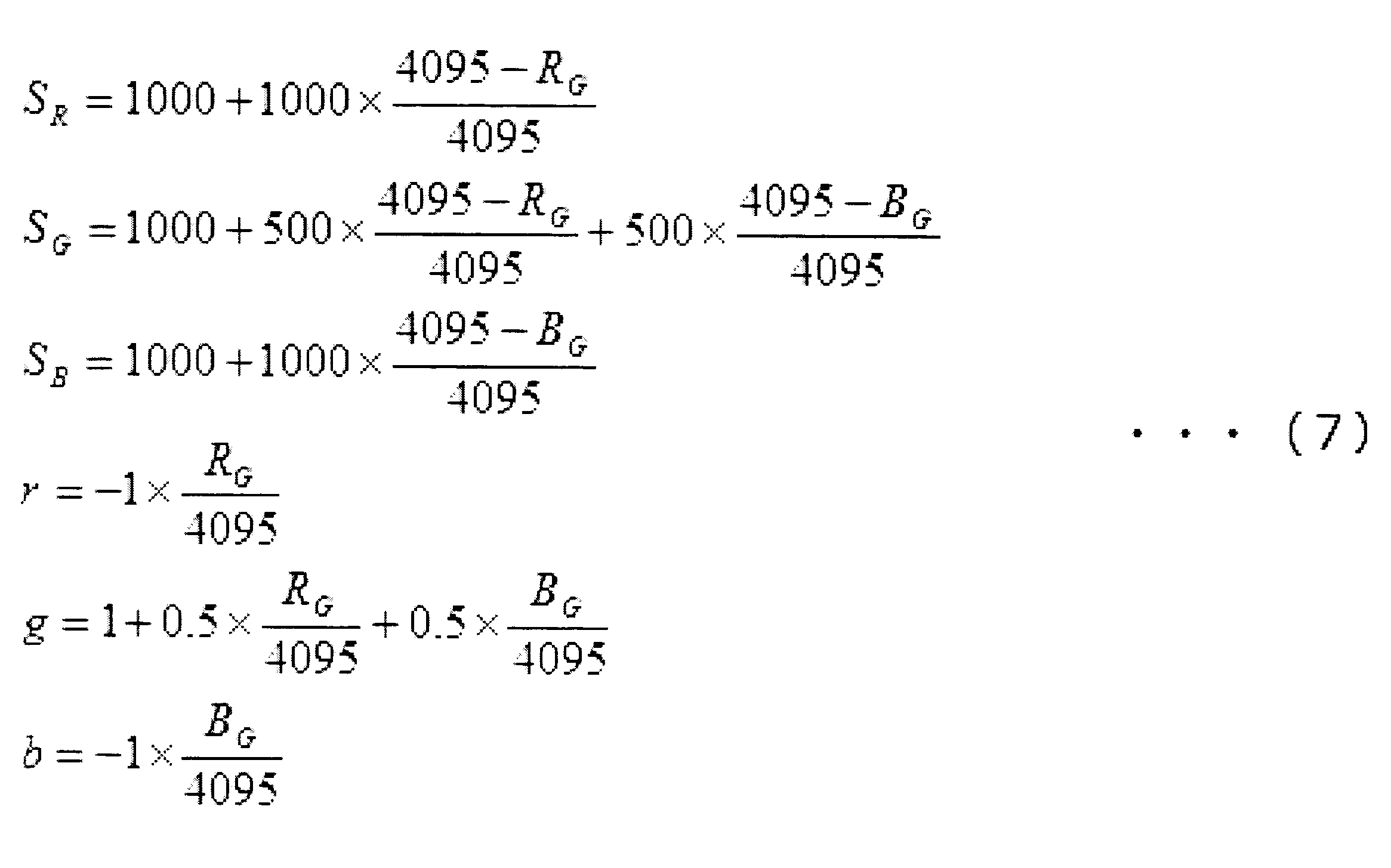
- the condition setting unit 63 replaces the tone value of each color component with the tone value of the G component to be emphasized, the R component to be reduced, and the following equation (7):
- Coefficients r, g, and b and threshold values S R , S G , and S B are set using a ratio with the gradation value of the B component.
- R G and B G in equation (7) are defined by equation (8).
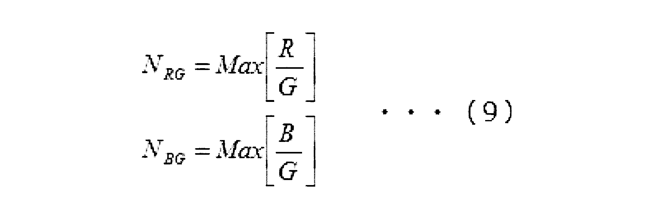
- NRG and NBG in the formula (8) are defined by the following formula (9).
- Max [R / G] represents the maximum value of R / B of all pixels, and Max [B / G] represents the maximum value of B / G of all pixels.
- each color component is more appropriately applied to the color component of the white light image G1.
- Image weights can be set.
- the condition setting unit 63 sets the weight depending on the G component of the white light image G1, instead of setting the weight depending on the R component and the B component of the white light image G1. To do. Specifically, as shown in the following equation (10), the condition setting unit 63 increases the positive weight for the G component image as the tone value of the G component is smaller, and the R component image and B The coefficients r, g, b and threshold values S R , S G , S B are set so that the negative weight for the component image is increased. Even in this way, the green color can be effectively enhanced in the fluorescent region Y of the composite image G3.
- the image processing unit 6 calculates the average value m and the standard deviation ⁇ of the gradation values from the distribution of the gradation values of the fluorescence image G2.
- a fluorescence image analysis unit 65 is further provided, and the condition setting unit 63 sets the thresholds S R , S B , and S G using the average value m and the standard deviation ⁇ calculated by the fluorescence image analysis unit 65.
- the fluorescence image analysis unit 65 and the condition setting unit 63 will be mainly described, and the same reference numerals are given to the components common to the first embodiment, and the description will be omitted.
- the fluorescence image analysis unit 65 calculates the distribution of gradation values in the entire fluorescence image G2 or a predetermined partial region of interest (ROI), and calculates the average value m of the gradation values of the fluorescence image G2 from the calculated distribution.
- the standard deviation ⁇ is calculated, and the obtained average value m and standard deviation ⁇ are output to the condition setting unit 63.
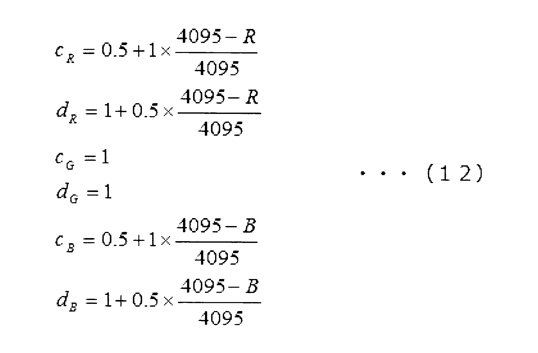
- the condition setting unit 63 calculates threshold values S R , S B , S G from the sum of the average value m of the gradation values input from the fluorescence image analysis unit 65 and the standard deviation ⁇ , as shown in the following equation (11).
- ci and di are coefficients that vary depending on the gradation value of the R component and the gradation value of the B component, and are defined by the following equation (12). Is done.
- the coefficients c R and c B vary between 0.5 and 1.5, and become smaller as the gradation values of the R component and the B component are larger.
- Coefficient d R, d B varies between 1 and 1.5, decreases as the gradation value of the R component and the B component is larger. Therefore, the stronger the redness and blueness in the white light image G1, the smaller the threshold values S R and S B and the greater the negative weight for the R component image and the B component image.
- the generation of the white light image G1 and the fluorescence image G2 (step S1) is performed in the same manner as in the first embodiment.
- the generated fluorescence image G2 is sent to the fluorescence image analysis unit 65.
- the distribution of the gradation value F of the fluorescence image G2 is calculated, and the average value m and the standard deviation ⁇ of the gradation value F are calculated from this distribution ( Step S5).
- step S3 using the threshold values S R , S G , and S B set in step S2 ′, a composite image G3 is generated based on equation (1).
- FIG. 5 shows an example of display on the display unit 7 according to the present embodiment, and shows a histogram (lower stage) of the gradation value F of the composite image G3 (upper stage) and the fluorescent image G2.
- threshold values S R , S G , and S B are displayed.
- the threshold values S R , S G , and S B calculated based on the average value m and the standard deviation ⁇ change according to the change in the distribution of the gradation value F, and the overall brightness of the fluorescent image G2 increases. In this case, the threshold values S R , S G , and S B are increased.
- the threshold values S R , S G , and S B change depending on the change in the overall gradation value of the fluorescent image G2 in addition to the color component of the white light image G1. . Therefore, when the overall brightness of the fluorescent image G2 changes due to changes in observation conditions such as the observation distance and observation angle between the distal end 2a of the insertion portion 2 and the subject X, the thresholds S R and S G, S B is also changed to a more appropriate value. As a result, the fluorescent region Y is more accurately extracted from the fluorescent image G2, and the negative weights attached to the R component image and the B component image are more appropriately set. Therefore, in the synthesized image G3, it is possible to display the more accurate fluorescent region Y and more appropriately emphasize the fluorescent region Y.
- the process of enhancing the G component according to the gradation value of the fluorescent image G2 has been described.
- the same method as described in the present embodiment is used. The method can be used.
- the condition setting unit 63 sets the negative weight for the R component image and the B component image depending on the color component of the white light image G1, and sets the positive weight for the G component image to white. It is set depending on the color component of the light image G1.
- the condition setting unit 63 as shown in the following equation (13), as the gradation value of the R component and the B component is larger in the white light image G1, as the threshold value S G becomes smaller, the coefficient c G and d G are set small. By doing so, the gradation value added as the fluorescent region Y to the white light image G1 can be increased, and the green color of the fluorescent region Y can be emphasized in the composite image G3. Further, according to the equation (13), since the R component and the B component are suppressed in the fluorescent region Y of the composite image G3, the green color of the fluorescent region Y can be more effectively emphasized.
- condition setting unit 63 combines the equations (12) and (13), and the coefficients c R , c G , c B , d R , d G are obtained as shown in the following equation (14).
- the d B may be varied simultaneously, depending on the color component of the white light image G1. In this way, the green color of the fluorescent region Y can be more effectively emphasized.
- the fluorescence observation apparatus 200 according to the present embodiment is a modification of the fluorescence observation apparatus 100 according to the second embodiment.
- the image processing unit 6 uses a white light image G1.
- the fluorescence image analysis unit 65 uses the fluorescence image G2 ′ corrected by the fluorescence image correction unit 66 to obtain an average value m ′ and a standard deviation.
- the main difference from the second embodiment is that ⁇ ′ is calculated. Therefore, in the present embodiment, the fluorescence image correction unit 66 and the fluorescence image analysis unit 65 will be mainly described, and the description of the configuration common to the first and second embodiments will be omitted.
- the fluorescence image correction unit 66 uses the gradation value of each pixel of the fluorescence image G2 input from the fluorescence image generation unit 62 according to the gradation value of each pixel of the white light image G1 input from the white light image generation unit 61. By performing the division, a fluorescent image (hereinafter referred to as a corrected fluorescent image) G2 ′ in which the gradation value is corrected is generated, and the generated corrected fluorescent image G2 ′ is output to the fluorescent image analysis unit 65.
- a corrected fluorescent image hereinafter referred to as a corrected fluorescent image
- the fluorescent image correction unit 66 corrects the pixel by dividing the gradation value F of the fluorescent image G2 by the gradation value of the R component of the white light image G1 for each pixel based on the following equation (15).
- a gradation value F ′ of the fluorescent image G2 ′ is calculated.
- N FR is a value defined by the following Expression (16), and is the maximum value among the quotients obtained by dividing the gradation value F by the gradation value R.
- the fluorescence image analysis unit 65 uses the corrected fluorescence image G2 ′ instead of the fluorescence image G2, and calculates the average value m ′ and the standard deviation ⁇ ′ of the gradation value F ′.
- the condition setting unit 63 uses the average value m ′ and the standard deviation ⁇ ′ instead of the average value m and the standard deviation ⁇ ′, and uses the threshold values S R , S G , S based on the equations (11) and (12). B is calculated.
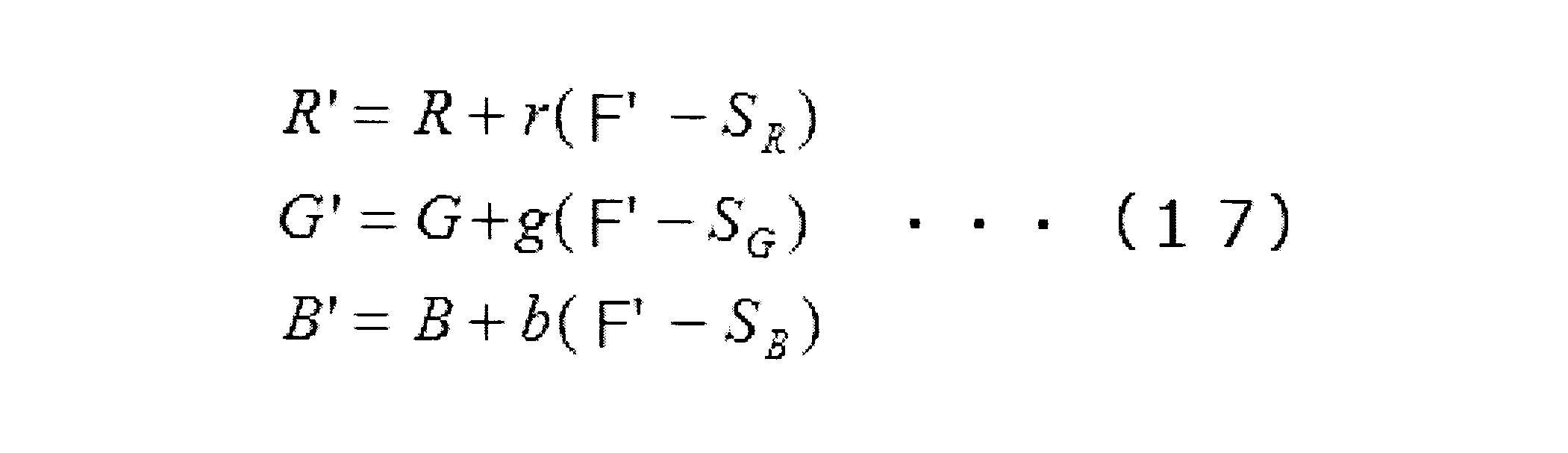
- the synthesizing unit 64 uses the corrected fluorescent image G2 ′ instead of the fluorescent image G2 based on the following equation (17) instead of the equation (1), that is, the pixel level of each color component image of the synthesized image G3.
- the adjustment value R′G′B ′ is calculated.
- the generation of the white light image G1 and the fluorescence image G2 (up to step S1 is performed in the same manner as in the first embodiment.
- the generated white light image G1 and the fluorescence image. G2 is sent to the fluorescent image correcting unit 66.
- the corrected fluorescent image G2 is generated by dividing the fluorescent image G2 by the white light image G1.
- the condition setting unit 63 uses the average value m ′ and the standard deviation ⁇ ′, and uses the threshold values S R and S G in the same manner as in step S2 ′ of the second embodiment. and S B is set (the scan -Up S2 ").
- the corrected fluorescence image G2 ' is used in place of the fluorescence image G2 in the fluorescence image analysis unit 65 and the synthesis unit 64.
- the corrected fluorescent image G2 ′ in which the gradation value is standardized using the white light image G1
- the change in the gradation value depending on the observation conditions such as the observation distance and the observation angle is removed, and each position of the subject X It is the image which reflected the original intensity
- a fluorescence observation apparatus 300 according to the fourth embodiment of the present invention will be described.
- the fluorescence observation apparatus 300 which of the R, G, and B components is emphasized by the image processing unit 6, that is, which color component is given a greater weight.
- An emphasis component determination unit 67 that determines whether or not a color image is included, and the condition setting unit 63 sets the coefficients r, g, and b and threshold values S R , S B , and S G based on the determination result of the emphasis component determination unit 67
- the enhancement component determination unit 67, the fluorescence image correction unit 66, and the fluorescence image analysis unit 65 will be mainly described, and the description of the configuration common to the first and second embodiments will be omitted.
- the enhancement component determination unit 67 determines the color component to be enhanced for each pixel based on the color component of each pixel of the white light image G1, and outputs the determination result for each pixel to the condition setting unit 63. For example, when the gradation value G of the G component of the white light image G1 is greater than or equal to a predetermined threshold, the enhancement component determination unit 67 determines the G component as an enhancement component and the R component and B component as non-enhancement components. When the gradation value of the G component of the white light image G1 is less than a predetermined threshold value, the B component is determined as an enhanced component, and the R component and the G component are determined as non-enhanced components.
- the condition setting unit 63 sets the coefficients r, g, b and the threshold values S R , S B , S G so that the weight for the emphasized component determined by the emphasized component determining unit 67 is larger than the weight for the non-emphasized component.
- the condition setting unit 63 uses Expression (2) for a pixel whose enhancement component is a G component, and uses an expression in which R and G are interchanged in Expression (2) for a pixel whose enhancement component is an R component.
- an equation in which B and G are exchanged in Equation (2) is used, and coefficients r, g, b and threshold values S R , S B , S G are set for each pixel.
- the composite image G3 with good visibility of the fluorescent region Y can be generated using the G component as an enhancement component.
- the G component is less than the threshold value, since the gradation value of the G component is small, the visibility of the fluorescent region Y is further improved by selecting a component other than the G component (B component or R component) as the enhancement component.
- the synthesized image G3 can be generated. As described above, it is possible to more appropriately select and determine the emphasis component according to the color component at each position of the white light image G1. Thereby, the visibility of the fluorescent region Y in the composite image G3 can be improved.
- the emphasis component determination unit 67 determines the emphasis component and the non-emphasis component based on the magnitude of the G component, but instead of this, the ratio of two color components, for example, The emphasis component and the non-emphasis component may be determined based on the ratio between the G component and the B component.
- the case where the combined image G3 is generated by assigning the fluorescent image G2 to the G component image has been described as an example.
- the color component image to which the fluorescent image G2 is assigned is described. Can be appropriately changed. That is, the fluorescence image G2 may be assigned to the R component image or the B component image, or may be divided and assigned to a plurality of component images.
- the formula (2) may be modified as the following formula (18).
- the composite image G3 is generated from the R component image and G component image with negative weights and the B component image with positive weights.
- the B component which is the display color of the fluorescent region Y can be emphasized with respect to the R component and the G component.
- the first to fourth embodiments described above may be implemented in any appropriate combination.
- the dynamic range of each image G1, G2, G2 ′, G3 is assumed to be 12 bits. However, this dynamic range is not limited to 12 bits. These can be changed as appropriate. For example, when a 16-bit image is used, 4095 may be replaced with 65535 in each expression (2) to (18).
- the numerical values ( ⁇ 1, 0.5, 1, 500, 1000) used in the above formulas (2) to (18) are merely examples, and can be changed as appropriate.
- the condition setting unit 63 continuously changes the weight assigned to each color component image. Instead, the weight is changed stepwise. It may be changed.
- the threshold values S R and S G may be defined as step functions of the gradation values R and B.
Abstract
Description
本発明は、写体に白色光および励起光を照射する光源と、該光源からの前記励起光の照射によって前記被写体において発生した蛍光を撮影して蛍光画像を生成する蛍光画像生成部と、前記光源からの前記白色光の照射によって前記被写体から戻る戻り光を撮影してカラーの白色光画像を生成する白色光画像生成部と、前記白色光画像を構成する複数の色成分画像の各々に対して重みを設定する条件設定部と、前記複数の色成分画像のうち少なくとも1つに前記蛍光画像を加算し、該蛍光画像が加算された色成分画像と他の色成分画像とを、前記条件設定部によって設定された重みを付して合成する合成部とを備え、前記条件設定部は、前記白色光画像の前記色成分画像に基づいて重みを設定し、かつ、前記蛍光画像が加算される色成分画像に対する重みが、前記他の色成分画像に対する重みよりも大きくなるように、前記複数の色成分画像に対する重みを設定する蛍光観察装置を提供する。 In order to achieve the above object, the present invention provides the following means.
The present invention includes a light source that irradiates a subject with white light and excitation light, a fluorescence image generation unit that captures fluorescence generated in the subject by irradiation of the excitation light from the light source, and generates a fluorescence image; A white light image generation unit that captures a return light returning from the subject by irradiation of the white light from a light source to generate a color white light image, and each of a plurality of color component images constituting the white light image A condition setting unit for setting weights, adding the fluorescent image to at least one of the plurality of color component images, and adding the color component image obtained by adding the fluorescent image and another color component image to the condition And a composition unit that combines the weights set by the setting unit, the condition setting unit sets weights based on the color component image of the white light image, and the fluorescence image is added Color component image Weights are the other so as to be larger than the weight for the color component images, to provide a fluorescence observation device for setting weights for the plurality of color component images.
このようにすることで、合成画像において、蛍光領域の表示色成分以外の色成分が多い程、表示色成分がより強調され、かつ/または、表示色成分以外の色成分がより抑制される。これにより、合成画像において蛍光領域をより効果的に強調することができる。 In the above invention, the condition setting unit increases the weight of the color component image to which the fluorescent image is added and / or increases the gradation value of the other color component image in the white light image. The weights of the other color component images may be set small.
By doing in this way, a display image color component is emphasized and / or a color component other than a display color component is more suppressed, so that there are many color components other than the display color component of a fluorescence area | region in a synthesized image. Thereby, it is possible to more effectively enhance the fluorescent region in the composite image.
このようにすることで、蛍光画像の階調値が大きい程、合成画像において、表示色成分がより強調され、かつ/または、表示色以外の色成分がより抑制される。これにより、合成画像において蛍光領域をより効果的に強調することができる。 In the above invention, the condition setting unit sets the weight based on the gradation value of the fluorescent image in addition to the color component image of the white light image, and the larger the gradation value of the fluorescent image, The weight of the color component image to which the fluorescent image is added may be set large and / or the weight of the other color component image may be set small.
By doing in this way, a display color component is emphasized more and / or color components other than a display color are suppressed more in a synthetic | combination image, so that the gradation value of a fluorescence image is large. Thereby, it is possible to more effectively enhance the fluorescent region in the composite image.
このようにすることで、蛍光画像のうち、微弱な蛍光やノイズを除去し、病変部を選択的に抽出して蛍光領域として合成画像に表示することができる。また、その他の領域においては、被写体の色合いを正確に表している白色光画像をそのまま表示することができる。 In the above invention, the combining unit may apply the weight only to a region having a gradation value equal to or greater than a predetermined threshold in the fluorescent image.
By doing so, it is possible to remove weak fluorescence and noise from the fluorescent image, selectively extract a lesion, and display it as a fluorescent region on the composite image. In other regions, a white light image that accurately represents the color of the subject can be displayed as it is.
このようにすることで、蛍光画像の全体的な明るさの変動に伴って所定の閾値が変動するので、病変部を正確に蛍光領域として抽出して合成画像に表示することができる。 In the above invention, a fluorescence image analysis unit that calculates an average value of gradation values of the fluorescence image and a standard deviation of the gradation values is provided, and the condition setting unit is calculated by the fluorescence image analysis unit. The predetermined threshold may be set based on the sum of the average value of the gradation values and the standard deviation.
By doing so, the predetermined threshold value fluctuates with the fluctuation of the overall brightness of the fluorescent image, so that the lesioned part can be accurately extracted as a fluorescent region and displayed on the composite image.
このようにすることで、観察距離および観察角度に依存した蛍光画像の階調値の変化を除去し、被写体において発生している蛍光の本来の強度をより正確に反映した蛍光画像が得られる。この補正された蛍光画像を用いることにより、より正確な平均値および標準偏差を算出することができる。 In the above invention, a fluorescence image correction unit that corrects a gradation value of the fluorescence image by dividing the fluorescence image by the white light image, and the fluorescence image analysis unit is corrected by the fluorescence image correction unit. The average value and the standard deviation may be calculated using a fluorescent image.
In this way, a change in the gradation value of the fluorescent image depending on the observation distance and the observation angle is removed, and a fluorescent image that more accurately reflects the original intensity of the fluorescence generated in the subject can be obtained. By using this corrected fluorescence image, a more accurate average value and standard deviation can be calculated.
このようにすることで、合成画像において、被写体において蛍光が発せられている領域およびその蛍光の強度をより正確に反映した蛍光領域を表示することができる。 In the above invention, the image processing apparatus includes a fluorescence image correction unit that corrects a gradation value of the fluorescence image by dividing the fluorescence image by the white light image, and the combining unit and the condition setting unit include the fluorescence image correction unit. The fluorescent image corrected by the above may be used as the fluorescent image.
By doing in this way, it is possible to display a region where fluorescence is emitted in the subject and a fluorescence region reflecting the intensity of the fluorescence more accurately in the composite image.
このようにすることで、白色光画像が有する色成分に応じてより適切に強調成分を選定し決定することができ、合成画像における蛍光領域の視認性を向上することができる。 The above-described invention may include an enhancement component determination unit that selects a color component image to which the fluorescent image is added according to the color component image of the white light image.
By doing in this way, an emphasis component can be selected and determined more appropriately according to the color component of the white light image, and the visibility of the fluorescent region in the composite image can be improved.
以下に、本発明の第1の実施形態に係る蛍光観察装置1について図1および図2を参照して説明する。
本実施形態に係る蛍光観察装置1は、内視鏡装置であって、図1に示されるように、体内に挿入される細長い挿入部2と、光源3と、該光源3からの励起光および白色光(参照光)を挿入部2の先端2aから被写体Xに向けて照射する照明ユニット4と、挿入部2の先端2aに設けられ、被写体Xの画像情報S1,S2を取得する撮像ユニット5と、挿入部2の基端側に配置され、撮像ユニット5によって取得された画像情報S1,S2を処理する画像処理ユニット6と、該画像処理ユニット6によって処理された画像G3を表示する表示部7とを備えている。 [First Embodiment]
Below, the
A

そこで、以下では、蛍光領域Yに対応する白色光画像G1のG成分が強調される合成画像G3を生成する場合を例に挙げて説明する。 In the present embodiment, since the color of the biological tissue that is the subject X includes a lot of R components, the display color of the fluorescent region Y in the composite image G3 is preferably green. Accordingly, weighting is performed such that the G component image of the white light image G1 corresponding to the fluorescent region Y is enhanced, and the green contrast is enhanced between the fluorescent region Y and the other regions in the composite image G3. Preferably, an image is generated.
Therefore, in the following, a case where the composite image G3 in which the G component of the white light image G1 corresponding to the fluorescent region Y is emphasized will be described as an example.
また、合成画像G3の生成において、白色光画像G1のR成分およびB成分については、蛍光画像G2の各画素の階調値Fを閾値SR,SBと比較し、閾値SR,SBよりも大きい階調値Fを有する領域を抽出し、抽出された領域に負の重みを付すことが好ましい。この重みは、係数r,g,bおよび閾値SR,SG,SBによって決定され、これら係数および閾値が条件設定部63によって設定される。 Combining
In the generation of the composite image G3, for the R component and B component of the white light image G1, the gradation value F of each pixel of the fluorescent image G2 is compared with the threshold values S R and S B, and the threshold values S R and S B It is preferable to extract a region having a larger gradation value F and to apply a negative weight to the extracted region. This weight is determined by coefficients r, g, b and threshold values S R , S G , S B , and these coefficients and threshold values are set by the

本実施形態に係る蛍光観察装置1を用いて被写体Xである体内の生体組織を観察するには、予め、病変部Zに集積する蛍光物質を被写体Xに投与しておく。そして、体内に挿入部2を挿入してその先端2aを被写体Xに対向配置し、光源3の作動によって励起光および白色光を挿入部2の先端2aから被写体Xに照射する。 Next, the operation of the
In order to observe the biological tissue in the body that is the subject X using the
画像処理ユニット6において、白色光画像情報S1が白色光画像生成部61に入力されて白色光画像G1が生成され、蛍光画像情報S2が蛍光画像生成部62に入力されて蛍光画像G2が生成される(ステップS1)。白色光画像G1は条件設定部63および条件設定部63に送られ、蛍光画像G2は合成部64に送られる。 FIG. 2 shows a flowchart for explaining image processing by the
In the

また、本実施形態においては、階調値のダイナミックレンジを12bitと仮定して説明したが、これに限らず、例えば8bitや16bitの場合でも同様の処理を行うことができる。すなわち、上記式(2),(3)において、定数4095に代えて、8bitのときには255を、16bitのときには65535を、それぞれ用いればよい。 Further, in the present embodiment, the expressions (2) and (3) may be combined, and both the threshold values S R and S B and the coefficients r and b may be changed simultaneously.
Further, in the present embodiment, the description has been made assuming that the dynamic range of the gradation value is 12 bits. However, the present invention is not limited to this, and the same processing can be performed even in the case of 8 bits or 16 bits, for example. That is, in the above formulas (2) and (3), instead of the constant 4095, 255 may be used for 8 bits and 65535 for 16 bits.
以下で述べる他の実施形態および変形例においても、本実施形態で述べたものと同様の効果を有する。
なお、上記の計算において、小数点以下の値はすべて切り捨て処理をしている。 Therefore, when the values of the threshold values S R , S G , and S B are appropriately changed according to the color components of the white light image G1 (A), the values of the threshold values S R , S G , and S B are always Compared to the fixed cases (B) and (C), in the synthesized image G3, the visibility of the G component reflecting the information of the fluorescent image G2 is ensured, and the information on the form of the subject X is as much as possible. A more appropriate image that remains can be presented.
Other embodiments and modifications described below have the same effects as those described in this embodiment.
In the above calculation, all values after the decimal point are rounded down.
(第1の実施形態の第1の変形例)
第1の変形例において、条件設定部63は、R成分画像およびB成分画像に対する負の重みを白色光画像G1の色成分に依存して設定することに代えて、G成分画像に対する正の重みを白色光画像G1の色成分に依存して設定する。 Next, a modified example of processing of the
(First modification of the first embodiment)
In the first modification, the
このようにすることで、白色光画像G1に蛍光領域Yとして加算される階調値を増大し、合成画像G3において蛍光領域Yの緑色を強調することができる。また、式(4)によれば、合成画像G3の蛍光領域Yにおいて、R成分およびB成分の階調値は、階調値Fが大きい程低減されるので、蛍光領域Yの緑色をさらに効果的に強調することができる。 Specifically, the
By doing so, the gradation value added as the fluorescent region Y to the white light image G1 can be increased, and the green color of the fluorescent region Y can be emphasized in the composite image G3. Further, according to the equation (4), in the fluorescent region Y of the composite image G3, the gradation values of the R component and the B component are reduced as the gradation value F increases, so that the green color of the fluorescent region Y is further effective. Can be emphasized.

第2の変形例において、条件設定部63は、各色成分の階調値に代えて、下式(7)に示されるように、強調すべきG成分の階調値と低減すべきR成分およびB成分の階調値との比を用いて、係数r,g,bおよび閾値SR,SG,SBを設定する。式(7)おけるRG、BGは、式(8)によって定義される。式(8)におけるNRGおよびNBGは、下式(9)によって定義される。Max[R/G]は、全ての画素のR/Bのうちの最大値を、Max[B/G]は、全ての画素のB/Gのうちの最大値を表す。 (Second modification of the first embodiment)
In the second modification, the

第3の変形例において、条件設定部63は、白色光画像G1のR成分およびB成分に依存して重みを設定することに代えて、白色光画像G1のG成分に依存して重みを設定する。
具体的には、条件設定部63は、下式(10)に示されるように、G成分の階調値が小さい程、G成分画像に対する正の重みが大きくなり、また、R成分画像およびB成分画像に対する負の重みが大きくなるように、係数r,g,bおよび閾値SR,SG,SBを設定する。
このようにしても、合成画像G3の蛍光領域Yにおいて、緑色を効果的に強調することができる。 (Third Modification of First Embodiment)
In the third modification, the
Specifically, as shown in the following equation (10), the
Even in this way, the green color can be effectively enhanced in the fluorescent region Y of the composite image G3.

次に、本発明の第2の実施形態に係る蛍光観察装置100について説明する。
本実施形態に係る蛍光観察装置100は、図3に示されるように、画像処理ユニット6が、蛍光画像G2の階調値の分布から該階調値の平均値mおよび標準偏差σを算出する蛍光画像解析部65をさらに備え、条件設定部63が、蛍光画像解析部65によって算出された平均値mおよび標準偏差σを用いて閾値SR,SB,SGを設定する点において、第1の実施形態と主に相違する。したがって、本実施形態においては、蛍光画像解析部65および条件設定部63について主に説明し、第1の実施形態と共通する構成については同一の符号を付して説明を省略する。 [Second Embodiment]
Next, a
In the

本実施形態に係る蛍光観察装置100によれば、白色光画像G1および蛍光画像G2の生成(ステップS1)までは、第1の実施形態と同様に行われる。生成された蛍光画像G2は、蛍光画像解析部65に送られる。蛍光画像解析部65においては、図4に示されるように、蛍光画像G2の階調値Fの分布が算出され、この分布から階調値Fの平均値mおよび標準偏差σが算出される(ステップS5)。次に、条件設定部63において、これら平均値mおよび標準偏差σ用いて閾値SR,SG,SBが設定される(ステップS2’)。ステップS3においては、ステップS2’において設定された閾値SR,SG,SBを用いて、式(1)に基づいて合成画像G3を生成する。 Next, the operation of the
According to the
次に、本実施形態の条件設定部63および合成部64の処理の変形例について説明する。
本変形例において、条件設定部63は、R成分画像およびB成分画像に対する負の重みを白色光画像G1の色成分に依存して設定することに代えて、G成分画像に対する正の重みを白色光画像G1の色成分に依存して設定する。 (Modification of the second embodiment)
Next, a modified example of the processing of the
In this modified example, the
このようにすることで、白色光画像G1に蛍光領域Yとして加算される階調値を増大し、合成画像G3において蛍光領域Yの緑色を強調することができる。また、式(13)によれば、合成画像G3の蛍光領域Yにおいて、R成分およびB成分が抑制されるので、蛍光領域Yの緑色をさらに効果的に強調することができる。 Specifically, the
By doing so, the gradation value added as the fluorescent region Y to the white light image G1 can be increased, and the green color of the fluorescent region Y can be emphasized in the composite image G3. Further, according to the equation (13), since the R component and the B component are suppressed in the fluorescent region Y of the composite image G3, the green color of the fluorescent region Y can be more effectively emphasized.

このようにすることで、蛍光領域Yの緑色をさらに効果的に強調することができる。 In this modification, the
In this way, the green color of the fluorescent region Y can be more effectively emphasized.

次に、本発明の第3の実施形態に係る蛍光観察装置200について説明する。
本実施形態に係る蛍光観察装置200は、第2の実施形態に係る蛍光観察装置100を変形したものであって、図6に示されるように、画像処理ユニット6が、白色光画像G1を用いて蛍光画像G2の階調値を補正する蛍光画像補正部66をさらに備え、蛍光画像解析部65が、蛍光画像補正部66によって補正された蛍光画像G2’を用いて平均値m’および標準偏差σ’を算出する点において、第2の実施形態と主に相違する。したがって、本実施形態においては、蛍光画像補正部66および蛍光画像解析部65について主に説明し、第1および第2の実施形態と共通する構成については説明を省略する。 [Third Embodiment]
Next, a
The


条件設定部63は、平均値mおよび標準偏差σ’に代えて平均値m’および標準偏差σ’を用いて、式(11)および式(12)に基づいて閾値SR,SG,SBを算出する。
合成部64は、式(1)に代えて下式(17)に基づいて、すなわち、蛍光画像G2に代えて補正蛍光画像G2’を用いて、合成画像G3の各色成分画像の各画素の階調値R’G’B’を算出する。 The fluorescence
The
The synthesizing
本実施形態に係る蛍光観察装置200によれば、白色光画像G1および蛍光画像G2の生成(ステップS1までは、第1の実施形態と同様に行われる。生成された白色光画像G1および蛍光画像G2は、蛍光画像補正部66に送られる。蛍光画像補正部66においては、図7に示されるように、蛍光画像G2が白色光画像G1によって除算されることにより、補正蛍光画像G2が生成される(ステップS6)。次に、蛍光画像解析部65において、補正蛍光画像G2’の階調値F’の分布が算出され、この分布から階調値F’の平均値m’および標準偏差σ’が算出される(ステップS5’)。次に、条件設定部63において、平均値m’および標準偏差σ’用い、第2の実施形態のステップS2’と同様にして閾値SR,SG,SBが設定される(ステップS2”)。 Next, the operation of the
According to the
次に、本発明の第4の実施形態に係る蛍光観察装置300について説明する。
本実施形態に係る蛍光観察装置300は、図8に示されるように、画像処理ユニット6が、R、G、B成分のうちいずれを強調するか、すなわち、いずれの色成分により大きな重みを付すかを決定する強調成分決定部67をさらに備え、条件設定部63が、強調成分決定部67の決定結果に基づいて係数r,g,bおよび閾値SR,SB,SGを設定する点において、第1から第3の実施形態と主に相違する。したがって、本実施形態においては、強調成分決定部67および蛍光画像補正部66および蛍光画像解析部65について主に説明し、第1および第2の実施形態と共通する構成については説明を省略する。 [Fourth Embodiment]
Next, a
As shown in FIG. 8, in the
このようにすることで、負の重みを付されたR成分画像およびG成分画像と、正の重みを付されたB成分画像とから合成画像G3が生成される。これにより、合成画像G3の蛍光領域Yにおいて、R成分およびG成分に対して、蛍光領域Yの表示色であるB成分を強調することができる。 For example, when the first embodiment is described as an example, the formula (2) may be modified as the following formula (18).
In this way, the composite image G3 is generated from the R component image and G component image with negative weights and the B component image with positive weights. Thereby, in the fluorescent region Y of the composite image G3, the B component which is the display color of the fluorescent region Y can be emphasized with respect to the R component and the G component.

また、上述した第1から第4の実施形態においては、各画像G1,G2,G2’,G3のダイナミックレンジを12bitと仮定して説明したが、このダイナミックレンジは12bitに限定されるものではなく、適宜変更可能である。例えば、16bitの画像を用いる場合には、各式(2)から(18)において4095を65535に代えればよい。
また、上述した式(2)から(18)に用いられている数値(-1、0.5、1、500、1000)は、一例であって、適宜変更可能である。 Further, the first to fourth embodiments described above may be implemented in any appropriate combination.
In the first to fourth embodiments described above, the dynamic range of each image G1, G2, G2 ′, G3 is assumed to be 12 bits. However, this dynamic range is not limited to 12 bits. These can be changed as appropriate. For example, when a 16-bit image is used, 4095 may be replaced with 65535 in each expression (2) to (18).
The numerical values (−1, 0.5, 1, 500, 1000) used in the above formulas (2) to (18) are merely examples, and can be changed as appropriate.
2 挿入部
3 光源
4 照明ユニット
5 撮像ユニット
6 画像処理ユニット
7 表示部
31 キセノンランプ
32 フィルタ
33 カップリングレンズ
41 ライトガイドファイバ
42 照明光学系
51 対物レンズ
52 ダイクロイックミラー
53,54 集光レンズ
55,56 撮像素子
57 励起光カットフィルタ
61 白色光画像生成部
62 蛍光画像生成部
63 条件設定部
64 合成部
65 蛍光画像解析部
66 蛍光画像補正部
67 強調成分決定部
G1 白色光画像
G2 蛍光画像
G2’ 補正蛍光画像
G3 合成画像
X 被写体
Y 蛍光領域
Z 病変部 1, 100, 200, 300
Claims (10)
- 被写体に白色光および励起光を照射する光源と、
該光源からの前記励起光の照射によって前記被写体において発生した蛍光を撮影して蛍光画像を生成する蛍光画像生成部と、
前記光源からの前記白色光の照射によって前記被写体から戻る戻り光を撮影してカラーの白色光画像を生成する白色光画像生成部と、
前記白色光画像を構成する複数の色成分画像の各々に対して重みを設定する条件設定部と、
前記複数の色成分画像のうち少なくとも1つに前記蛍光画像を加算し、該蛍光画像が加算された色成分画像と他の色成分画像とを、前記条件設定部によって設定された重みを付して合成する合成部とを備え、
前記条件設定部は、前記白色光画像の前記色成分画像に基づいて重みを設定し、かつ、前記蛍光画像が加算される色成分画像に対する重みが、前記他の色成分画像に対する重みよりも大きくなるように、前記複数の色成分画像に対する重みを設定する蛍光観察装置。 A light source that irradiates the subject with white light and excitation light;
A fluorescence image generation unit that captures fluorescence generated in the subject by irradiation of the excitation light from the light source and generates a fluorescence image;
A white light image generating unit that captures a return light returning from the subject by irradiation of the white light from the light source and generates a color white light image;
A condition setting unit for setting a weight for each of a plurality of color component images constituting the white light image;
The fluorescent image is added to at least one of the plurality of color component images, and the color component image to which the fluorescent image is added and the other color component image are given weights set by the condition setting unit. And a synthesizing unit that synthesizes
The condition setting unit sets a weight based on the color component image of the white light image, and a weight for the color component image to which the fluorescent image is added is larger than a weight for the other color component image. A fluorescence observation apparatus that sets weights for the plurality of color component images. - 前記条件設定部は、前記白色光画像における前記他の色成分画像の階調値が大きい程、前記蛍光画像が加算される色成分画像の重みを大きく設定する請求項1に記載の蛍光観察装置。 2. The fluorescence observation apparatus according to claim 1, wherein the condition setting unit sets the weight of the color component image to which the fluorescence image is added as the gradation value of the other color component image in the white light image is larger. .
- 前記条件設定部は、前記白色光画像における前記他の色成分画像の階調値が大きい程、前記他の色成分画像の重みを小さく設定する請求項1または請求項2に記載の蛍光観察装置。 The fluorescence observation apparatus according to claim 1, wherein the condition setting unit sets the weight of the other color component image to be smaller as the gradation value of the other color component image in the white light image is larger. .
- 前記条件設定部は、前記白色光画像の色成分画像に加えて前記蛍光画像の階調値に基づいて前記重みを設定し、前記蛍光画像の階調値が大きい程、前記蛍光画像が加算される色成分画像の重みを大きく設定する請求項1から請求項3のいずれかに記載の蛍光観察装置。 The condition setting unit sets the weight based on the gradation value of the fluorescent image in addition to the color component image of the white light image. The larger the gradation value of the fluorescent image, the more the fluorescent image is added. The fluorescence observation apparatus according to claim 1, wherein the weight of the color component image to be set is set large.
- 前記条件設定部は、前記白色光画像の色成分画像に加えて前記蛍光画像の階調値に基づいて前記重みを設定し、前記蛍光画像の階調値が大きい程、前記他の色成分画像の重みを小さく設定する請求項1から請求項4のいずれかに記載の蛍光観察装置。 The condition setting unit sets the weight based on the gradation value of the fluorescent image in addition to the color component image of the white light image, and the larger the gradation value of the fluorescent image, the more the other color component image The fluorescence observation apparatus according to any one of claims 1 to 4, wherein the weight is set to be small.
- 前記合成部が、前記蛍光画像において所定の閾値以上の階調値を有する領域に対してのみ前記重みを付す請求項1から請求項5のいずれかに記載の蛍光観察装置。 The fluorescence observation apparatus according to any one of claims 1 to 5, wherein the combining unit applies the weight only to a region having a gradation value equal to or greater than a predetermined threshold in the fluorescence image.
- 前記蛍光画像の階調値の平均値とその階調値の標準偏差とを算出する蛍光画像解析部を備え、
前記条件設定部が、前記蛍光画像解析部によって算出された前記階調値の平均値と標準偏差との和に基づいて前記所定の閾値を設定する請求項6に記載の蛍光観察装置。 A fluorescence image analysis unit for calculating an average value of the gradation values of the fluorescence image and a standard deviation of the gradation values;
The fluorescence observation apparatus according to claim 6, wherein the condition setting unit sets the predetermined threshold based on a sum of an average value and a standard deviation of the gradation values calculated by the fluorescence image analysis unit. - 前記蛍光画像を前記白色光画像で除算することにより前記蛍光画像の階調値を補正する蛍光画像補正部を備え、
前記蛍光画像解析部が、前記蛍光画像補正部によって補正された蛍光画像を用いて前記平均値および前記標準偏差を算出する請求項7に記載の蛍光観察装置。 A fluorescence image correction unit that corrects a gradation value of the fluorescence image by dividing the fluorescence image by the white light image;
The fluorescence observation apparatus according to claim 7, wherein the fluorescence image analysis unit calculates the average value and the standard deviation using the fluorescence image corrected by the fluorescence image correction unit. - 前記蛍光画像を前記白色光画像で除算することにより前記蛍光画像の階調値を補正する蛍光画像補正部を備え、
前記合成部および前記条件設定部が、前記蛍光画像補正部によって補正された蛍光画像を前記蛍光画像として用いる請求項1から請求項6のいずれかに記載の蛍光観察装置。 A fluorescence image correction unit that corrects a gradation value of the fluorescence image by dividing the fluorescence image by the white light image;
The fluorescence observation apparatus according to claim 1, wherein the synthesis unit and the condition setting unit use a fluorescence image corrected by the fluorescence image correction unit as the fluorescence image. - 前記白色光画像の前記色成分画像に応じて前記蛍光画像が加算される色成分画像を選定する強調成分決定部を備える請求項1から請求項9のいずれかに記載の蛍光観察装置。 The fluorescence observation apparatus according to any one of claims 1 to 9, further comprising an enhancement component determination unit that selects a color component image to which the fluorescence image is added according to the color component image of the white light image.
Priority Applications (4)
| Application Number | Priority Date | Filing Date | Title |
|---|---|---|---|
| EP14773962.7A EP2979611A4 (en) | 2013-03-29 | 2014-03-03 | Fluorescence observation device |
| JP2015508216A JP6391562B2 (en) | 2013-03-29 | 2014-03-03 | Fluorescence observation equipment |
| CN201480016558.7A CN105101861B (en) | 2013-03-29 | 2014-03-03 | Fluorescence observation device |
| US14/865,499 US10219701B2 (en) | 2013-03-29 | 2015-09-25 | Fluorescence observation apparatus |
Applications Claiming Priority (2)
| Application Number | Priority Date | Filing Date | Title |
|---|---|---|---|
| JP2013-073050 | 2013-03-29 | ||
| JP2013073050 | 2013-03-29 |
Related Child Applications (1)
| Application Number | Title | Priority Date | Filing Date |
|---|---|---|---|
| US14/865,499 Continuation US10219701B2 (en) | 2013-03-29 | 2015-09-25 | Fluorescence observation apparatus |
Publications (1)
| Publication Number | Publication Date |
|---|---|
| WO2014156493A1 true WO2014156493A1 (en) | 2014-10-02 |
Family
ID=51623483
Family Applications (1)
| Application Number | Title | Priority Date | Filing Date |
|---|---|---|---|
| PCT/JP2014/055321 WO2014156493A1 (en) | 2013-03-29 | 2014-03-03 | Fluorescence observation device |
Country Status (5)
| Country | Link |
|---|---|
| US (1) | US10219701B2 (en) |
| EP (1) | EP2979611A4 (en) |
| JP (1) | JP6391562B2 (en) |
| CN (1) | CN105101861B (en) |
| WO (1) | WO2014156493A1 (en) |
Cited By (4)
| Publication number | Priority date | Publication date | Assignee | Title |
|---|---|---|---|---|
| JP2018134413A (en) * | 2018-02-21 | 2018-08-30 | 株式会社島津製作所 | Imaging apparatus |
| JP2020524572A (en) * | 2017-06-22 | 2020-08-20 | ヘルムホルツ ツェントラム ミュンヘン ドイチェス フォーシュングスツェントラム フュール ゲズントハイト ウント ウンヴェルト ゲーエムベーハーHelmholtz Zentrum Muenchen Deutsches Forschungszentrum Fuer Gesundheit Und Umwelt Gmbh | System for endoscopic imaging and method for processing images |
| WO2021075418A1 (en) * | 2019-10-18 | 2021-04-22 | 国立大学法人鳥取大学 | Image processing method, teacher data generation method, trained model generation method, illness development prediction method, image processing device, image processing program, and recording medium on which program is recorded |
| WO2023112916A1 (en) * | 2021-12-16 | 2023-06-22 | i-PRO株式会社 | Video signal processing device, video signal processing method, and video signal processing system |
Families Citing this family (10)
| Publication number | Priority date | Publication date | Assignee | Title |
|---|---|---|---|---|
| EP3037030A4 (en) | 2013-08-23 | 2017-04-19 | Olympus Corporation | Fluorescence observation apparatus |
| KR101580075B1 (en) * | 2015-01-23 | 2016-01-21 | 김용한 | Lighting treatment device through analysis of image for lesion, method for detecting lesion position by analysis of image for lesion and recording medium recording method readable by computing device |
| WO2017175452A1 (en) * | 2016-04-04 | 2017-10-12 | ソニー株式会社 | Image processing device, image pickup device, image processing method, and program |
| DE102017125799A1 (en) * | 2017-11-06 | 2019-05-09 | Carl Zeiss Industrielle Messtechnik Gmbh | Reduction of picture disturbances in pictures |
| JP7281308B2 (en) * | 2019-03-07 | 2023-05-25 | ソニー・オリンパスメディカルソリューションズ株式会社 | Medical image processing device and medical observation system |
| US11733503B2 (en) * | 2019-11-14 | 2023-08-22 | Leica Instruments (Singapore) Pte. Ltd. | System and a method for generating output image data and a microscope |
| TWI726614B (en) * | 2020-02-12 | 2021-05-01 | 財團法人國家實驗研究院 | Detection method of biological fluorescence image |
| JP2021132695A (en) * | 2020-02-21 | 2021-09-13 | ソニー・オリンパスメディカルソリューションズ株式会社 | Medical image processing device, medical observation system, and image processing method |
| CN111449611B (en) * | 2020-04-10 | 2021-04-09 | 深圳迈瑞生物医疗电子股份有限公司 | Endoscope system and imaging method thereof |
| DE102021203187B3 (en) | 2021-03-30 | 2022-02-24 | Carl Zeiss Meditec Ag | Method for providing an image using a surgical microscope and surgical microscope |
Citations (10)
| Publication number | Priority date | Publication date | Assignee | Title |
|---|---|---|---|---|
| JPH10309282A (en) * | 1997-05-13 | 1998-11-24 | Olympus Optical Co Ltd | Fluorescent observation device |
| JP2005204958A (en) | 2004-01-23 | 2005-08-04 | Pentax Corp | Autofluorescently observable electronic endoscope apparatus and system |
| JP2009226072A (en) * | 2008-03-24 | 2009-10-08 | Fujifilm Corp | Method and device for surgical operation support |
| JP4533673B2 (en) | 2004-06-07 | 2010-09-01 | オリンパス株式会社 | Infrared observation system and operation method by infrared observation system |
| JP2010227254A (en) * | 2009-03-26 | 2010-10-14 | Olympus Corp | Image processor, imaging device, image processing program, and image processing method |
| WO2010122884A1 (en) * | 2009-04-21 | 2010-10-28 | オリンパスメディカルシステムズ株式会社 | Fluorescence image device and fluorescence image acquiring method |
| WO2011135992A1 (en) * | 2010-04-28 | 2011-11-03 | オリンパス株式会社 | Image processing device and fluorescent light observation device |
| JP2012147927A (en) * | 2011-01-19 | 2012-08-09 | Fujifilm Corp | Endoscope system |
| JP2012147935A (en) * | 2011-01-19 | 2012-08-09 | Fujifilm Corp | Endoscope system |
| JP2013039275A (en) * | 2011-08-18 | 2013-02-28 | Olympus Corp | Fluorescence observation device, fluorescence observation system and method for processing fluorescence image |
Family Cites Families (1)
| Publication number | Priority date | Publication date | Assignee | Title |
|---|---|---|---|---|
| JP5592715B2 (en) | 2010-07-02 | 2014-09-17 | オリンパス株式会社 | Image processing apparatus and image processing method |
-
2014
- 2014-03-03 JP JP2015508216A patent/JP6391562B2/en active Active
- 2014-03-03 EP EP14773962.7A patent/EP2979611A4/en not_active Withdrawn
- 2014-03-03 WO PCT/JP2014/055321 patent/WO2014156493A1/en active Application Filing
- 2014-03-03 CN CN201480016558.7A patent/CN105101861B/en not_active Expired - Fee Related
-
2015
- 2015-09-25 US US14/865,499 patent/US10219701B2/en active Active
Patent Citations (10)
| Publication number | Priority date | Publication date | Assignee | Title |
|---|---|---|---|---|
| JPH10309282A (en) * | 1997-05-13 | 1998-11-24 | Olympus Optical Co Ltd | Fluorescent observation device |
| JP2005204958A (en) | 2004-01-23 | 2005-08-04 | Pentax Corp | Autofluorescently observable electronic endoscope apparatus and system |
| JP4533673B2 (en) | 2004-06-07 | 2010-09-01 | オリンパス株式会社 | Infrared observation system and operation method by infrared observation system |
| JP2009226072A (en) * | 2008-03-24 | 2009-10-08 | Fujifilm Corp | Method and device for surgical operation support |
| JP2010227254A (en) * | 2009-03-26 | 2010-10-14 | Olympus Corp | Image processor, imaging device, image processing program, and image processing method |
| WO2010122884A1 (en) * | 2009-04-21 | 2010-10-28 | オリンパスメディカルシステムズ株式会社 | Fluorescence image device and fluorescence image acquiring method |
| WO2011135992A1 (en) * | 2010-04-28 | 2011-11-03 | オリンパス株式会社 | Image processing device and fluorescent light observation device |
| JP2012147927A (en) * | 2011-01-19 | 2012-08-09 | Fujifilm Corp | Endoscope system |
| JP2012147935A (en) * | 2011-01-19 | 2012-08-09 | Fujifilm Corp | Endoscope system |
| JP2013039275A (en) * | 2011-08-18 | 2013-02-28 | Olympus Corp | Fluorescence observation device, fluorescence observation system and method for processing fluorescence image |
Non-Patent Citations (1)
| Title |
|---|
| See also references of EP2979611A4 |
Cited By (4)
| Publication number | Priority date | Publication date | Assignee | Title |
|---|---|---|---|---|
| JP2020524572A (en) * | 2017-06-22 | 2020-08-20 | ヘルムホルツ ツェントラム ミュンヘン ドイチェス フォーシュングスツェントラム フュール ゲズントハイト ウント ウンヴェルト ゲーエムベーハーHelmholtz Zentrum Muenchen Deutsches Forschungszentrum Fuer Gesundheit Und Umwelt Gmbh | System for endoscopic imaging and method for processing images |
| JP2018134413A (en) * | 2018-02-21 | 2018-08-30 | 株式会社島津製作所 | Imaging apparatus |
| WO2021075418A1 (en) * | 2019-10-18 | 2021-04-22 | 国立大学法人鳥取大学 | Image processing method, teacher data generation method, trained model generation method, illness development prediction method, image processing device, image processing program, and recording medium on which program is recorded |
| WO2023112916A1 (en) * | 2021-12-16 | 2023-06-22 | i-PRO株式会社 | Video signal processing device, video signal processing method, and video signal processing system |
Also Published As
| Publication number | Publication date |
|---|---|
| CN105101861B (en) | 2017-05-24 |
| JPWO2014156493A1 (en) | 2017-02-16 |
| EP2979611A4 (en) | 2016-12-14 |
| JP6391562B2 (en) | 2018-09-19 |
| US10219701B2 (en) | 2019-03-05 |
| US20160007856A1 (en) | 2016-01-14 |
| EP2979611A1 (en) | 2016-02-03 |
| CN105101861A (en) | 2015-11-25 |
Similar Documents
| Publication | Publication Date | Title |
|---|---|---|
| JP6391562B2 (en) | Fluorescence observation equipment | |
| JP6188721B2 (en) | Fluorescence observation equipment | |
| JP5816486B2 (en) | Fluorescence observation apparatus, fluorescence observation system, and fluorescence image processing method of fluorescence observation apparatus | |
| JP6461797B2 (en) | Fluorescence observation equipment | |
| JP5498481B2 (en) | Fluorescence observation apparatus, fluorescence observation system, operation method of fluorescence observation apparatus, and fluorescence image processing method performed by fluorescence observation apparatus | |
| US9513221B2 (en) | Fluorescence observation apparatus | |
| WO2013015120A1 (en) | Fluorescence endoscopy system | |
| US9052286B2 (en) | Fluorescence endoscope apparatus | |
| WO2013035450A1 (en) | Fluorescence observation device | |
| US20140184769A1 (en) | Fluorescence observation apparatus | |
| JP5558178B2 (en) | Fluorescence observation equipment | |
| JP5669828B2 (en) | Image processing apparatus and fluorescence observation apparatus | |
| US20120323072A1 (en) | Fluorescence endoscope device | |
| JP2010220894A (en) | Fluorescence observation system, fluorescence observation device and fluorescence observation method | |
| WO2010110120A1 (en) | Fluorescence observation device, fluorescence observation system, and fluorescence image processing method | |
| JP5498282B2 (en) | Fluorescence observation equipment | |
| JP5592715B2 (en) | Image processing apparatus and image processing method | |
| WO2012176285A1 (en) | Fluorescence observation device, fluorescence observation system and fluorescent light image processing method | |
| JP5592700B2 (en) | Fluorescence observation apparatus, fluorescence observation system, and operation method of fluorescence observation apparatus |
Legal Events
| Date | Code | Title | Description |
|---|---|---|---|
| WWE | Wipo information: entry into national phase |
Ref document number: 201480016558.7 Country of ref document: CN |
|
| 121 | Ep: the epo has been informed by wipo that ep was designated in this application |
Ref document number: 14773962 Country of ref document: EP Kind code of ref document: A1 |
|
| ENP | Entry into the national phase |
Ref document number: 2015508216 Country of ref document: JP Kind code of ref document: A |
|
| NENP | Non-entry into the national phase |
Ref country code: DE |
|
| WWE | Wipo information: entry into national phase |
Ref document number: 2014773962 Country of ref document: EP |