WO2014156253A1 - 内視鏡装置 - Google Patents
内視鏡装置 Download PDFInfo
- Publication number
- WO2014156253A1 WO2014156253A1 PCT/JP2014/051368 JP2014051368W WO2014156253A1 WO 2014156253 A1 WO2014156253 A1 WO 2014156253A1 JP 2014051368 W JP2014051368 W JP 2014051368W WO 2014156253 A1 WO2014156253 A1 WO 2014156253A1
- Authority
- WO
- WIPO (PCT)
- Prior art keywords
- illumination
- brightness
- light
- band
- processing unit
- Prior art date
Links
- 238000012545 processing Methods 0.000 claims abstract description 152
- 238000005286 illumination Methods 0.000 claims abstract description 129
- 238000003384 imaging method Methods 0.000 claims abstract description 46
- 239000000203 mixture Substances 0.000 claims abstract description 28
- 239000011159 matrix material Substances 0.000 claims description 50
- 230000015572 biosynthetic process Effects 0.000 claims description 21
- 238000003786 synthesis reaction Methods 0.000 claims description 21
- 238000006243 chemical reaction Methods 0.000 claims description 9
- 230000003247 decreasing effect Effects 0.000 claims description 2
- 239000002131 composite material Substances 0.000 abstract description 17
- 239000000835 fiber Substances 0.000 description 8
- 238000010586 diagram Methods 0.000 description 7
- 230000005540 biological transmission Effects 0.000 description 5
- 238000003780 insertion Methods 0.000 description 5
- 230000037431 insertion Effects 0.000 description 5
- 238000012937 correction Methods 0.000 description 4
- 230000003287 optical effect Effects 0.000 description 4
- 238000000034 method Methods 0.000 description 3
- 201000005569 Gout Diseases 0.000 description 2
- 238000013459 approach Methods 0.000 description 2
- 210000004204 blood vessel Anatomy 0.000 description 2
- 239000003086 colorant Substances 0.000 description 2
- 230000006866 deterioration Effects 0.000 description 2
- 230000001678 irradiating effect Effects 0.000 description 2
- 230000002093 peripheral effect Effects 0.000 description 2
- 239000002344 surface layer Substances 0.000 description 2
- 230000003321 amplification Effects 0.000 description 1
- 239000008280 blood Substances 0.000 description 1
- 210000004369 blood Anatomy 0.000 description 1
- 230000007423 decrease Effects 0.000 description 1
- 238000001514 detection method Methods 0.000 description 1
- 230000006870 function Effects 0.000 description 1
- 238000012986 modification Methods 0.000 description 1
- 230000004048 modification Effects 0.000 description 1
- 238000003199 nucleic acid amplification method Methods 0.000 description 1
- 239000010453 quartz Substances 0.000 description 1
- VYPSYNLAJGMNEJ-UHFFFAOYSA-N silicon dioxide Inorganic materials O=[Si]=O VYPSYNLAJGMNEJ-UHFFFAOYSA-N 0.000 description 1
- 229910052724 xenon Inorganic materials 0.000 description 1
- FHNFHKCVQCLJFQ-UHFFFAOYSA-N xenon atom Chemical compound [Xe] FHNFHKCVQCLJFQ-UHFFFAOYSA-N 0.000 description 1
Images


Classifications
-
- A—HUMAN NECESSITIES
- A61—MEDICAL OR VETERINARY SCIENCE; HYGIENE
- A61B—DIAGNOSIS; SURGERY; IDENTIFICATION
- A61B1/00—Instruments for performing medical examinations of the interior of cavities or tubes of the body by visual or photographical inspection, e.g. endoscopes; Illuminating arrangements therefor
- A61B1/00002—Operational features of endoscopes
- A61B1/00004—Operational features of endoscopes characterised by electronic signal processing
- A61B1/00009—Operational features of endoscopes characterised by electronic signal processing of image signals during a use of endoscope
-
- A—HUMAN NECESSITIES
- A61—MEDICAL OR VETERINARY SCIENCE; HYGIENE
- A61B—DIAGNOSIS; SURGERY; IDENTIFICATION
- A61B1/00—Instruments for performing medical examinations of the interior of cavities or tubes of the body by visual or photographical inspection, e.g. endoscopes; Illuminating arrangements therefor
- A61B1/04—Instruments for performing medical examinations of the interior of cavities or tubes of the body by visual or photographical inspection, e.g. endoscopes; Illuminating arrangements therefor combined with photographic or television appliances
- A61B1/05—Instruments for performing medical examinations of the interior of cavities or tubes of the body by visual or photographical inspection, e.g. endoscopes; Illuminating arrangements therefor combined with photographic or television appliances characterised by the image sensor, e.g. camera, being in the distal end portion
-
- A—HUMAN NECESSITIES
- A61—MEDICAL OR VETERINARY SCIENCE; HYGIENE
- A61B—DIAGNOSIS; SURGERY; IDENTIFICATION
- A61B1/00—Instruments for performing medical examinations of the interior of cavities or tubes of the body by visual or photographical inspection, e.g. endoscopes; Illuminating arrangements therefor
- A61B1/06—Instruments for performing medical examinations of the interior of cavities or tubes of the body by visual or photographical inspection, e.g. endoscopes; Illuminating arrangements therefor with illuminating arrangements
- A61B1/0638—Instruments for performing medical examinations of the interior of cavities or tubes of the body by visual or photographical inspection, e.g. endoscopes; Illuminating arrangements therefor with illuminating arrangements providing two or more wavelengths
-
- A—HUMAN NECESSITIES
- A61—MEDICAL OR VETERINARY SCIENCE; HYGIENE
- A61B—DIAGNOSIS; SURGERY; IDENTIFICATION
- A61B1/00—Instruments for performing medical examinations of the interior of cavities or tubes of the body by visual or photographical inspection, e.g. endoscopes; Illuminating arrangements therefor
- A61B1/06—Instruments for performing medical examinations of the interior of cavities or tubes of the body by visual or photographical inspection, e.g. endoscopes; Illuminating arrangements therefor with illuminating arrangements
- A61B1/0646—Instruments for performing medical examinations of the interior of cavities or tubes of the body by visual or photographical inspection, e.g. endoscopes; Illuminating arrangements therefor with illuminating arrangements with illumination filters
-
- A—HUMAN NECESSITIES
- A61—MEDICAL OR VETERINARY SCIENCE; HYGIENE
- A61B—DIAGNOSIS; SURGERY; IDENTIFICATION
- A61B1/00—Instruments for performing medical examinations of the interior of cavities or tubes of the body by visual or photographical inspection, e.g. endoscopes; Illuminating arrangements therefor
- A61B1/06—Instruments for performing medical examinations of the interior of cavities or tubes of the body by visual or photographical inspection, e.g. endoscopes; Illuminating arrangements therefor with illuminating arrangements
- A61B1/07—Instruments for performing medical examinations of the interior of cavities or tubes of the body by visual or photographical inspection, e.g. endoscopes; Illuminating arrangements therefor with illuminating arrangements using light-conductive means, e.g. optical fibres
-
- G—PHYSICS
- G06—COMPUTING; CALCULATING OR COUNTING
- G06T—IMAGE DATA PROCESSING OR GENERATION, IN GENERAL
- G06T5/00—Image enhancement or restoration
- G06T5/50—Image enhancement or restoration using two or more images, e.g. averaging or subtraction
-
- G—PHYSICS
- G06—COMPUTING; CALCULATING OR COUNTING
- G06T—IMAGE DATA PROCESSING OR GENERATION, IN GENERAL
- G06T2207/00—Indexing scheme for image analysis or image enhancement
- G06T2207/10—Image acquisition modality
- G06T2207/10024—Color image
-
- G—PHYSICS
- G06—COMPUTING; CALCULATING OR COUNTING
- G06T—IMAGE DATA PROCESSING OR GENERATION, IN GENERAL
- G06T2207/00—Indexing scheme for image analysis or image enhancement
- G06T2207/10—Image acquisition modality
- G06T2207/10068—Endoscopic image
-
- G—PHYSICS
- G06—COMPUTING; CALCULATING OR COUNTING
- G06T—IMAGE DATA PROCESSING OR GENERATION, IN GENERAL
- G06T2207/00—Indexing scheme for image analysis or image enhancement
- G06T2207/10—Image acquisition modality
- G06T2207/10141—Special mode during image acquisition
- G06T2207/10152—Varying illumination
-
- G—PHYSICS
- G06—COMPUTING; CALCULATING OR COUNTING
- G06T—IMAGE DATA PROCESSING OR GENERATION, IN GENERAL
- G06T2207/00—Indexing scheme for image analysis or image enhancement
- G06T2207/20—Special algorithmic details
- G06T2207/20212—Image combination
- G06T2207/20221—Image fusion; Image merging
-
- G—PHYSICS
- G06—COMPUTING; CALCULATING OR COUNTING
- G06T—IMAGE DATA PROCESSING OR GENERATION, IN GENERAL
- G06T2207/00—Indexing scheme for image analysis or image enhancement
- G06T2207/30—Subject of image; Context of image processing
- G06T2207/30004—Biomedical image processing
Definitions
- the present invention relates to an endoscope apparatus suitable for narrowband light observation.
- a medical endoscope requires a light source device that illuminates the inside of the living body because the site to be observed is inside the living body. Illumination light generated by the light source device is irradiated to the observation target tissue from the distal end portion where the imaging unit is located through a light guide inserted through the insertion portion of the endoscope.
- white light sources are transmitted through a rotary filter, so that illumination light of three colors of R, G, and B is sequentially irradiated onto a tissue in a body cavity. Then, the reflected light images corresponding to the three colors of R, G, and B are acquired in a time-sharing manner, and a color image for performing normal light observation is generated from each reflected light image.
- the invention of International Publication No. WO2010 / 131620 is configured to be capable of sequentially irradiating green narrowband light G and two blue narrowband lights B1 and B2.
- narrowband light observation is performed using a narrowband light observation image created from reflected light images (narrowband images) corresponding to the narrowband light G, B1, and B2. It has become.
- it is used for addition of an image obtained when the narrowband light B1 is irradiated and an image obtained when the narrowband light B2 is irradiated. The amount of addition is determined based on the average brightness of the image.
- the present invention has been made in view of the above-described circumstances, and an object of the present invention is to provide an endoscope apparatus capable of improving the image quality of a narrow-band light observation image as compared with the conventional art.
- the endoscope apparatus performs illumination with illumination light of the first band once in a predetermined time, and illumination with illumination light of the second band N times (N ⁇ 2).
- an illuminating unit to be performed, and a subject illuminated by the illuminating unit are imaged, and a first imaging signal based on illumination of illumination light in the first band and illumination based on illumination of illumination light in the second band
- An image pickup unit that outputs two image pickup signals
- a clip processing unit that performs processing for limiting upper limit values of luminance values in the first image pickup signal and the second image pickup signal according to a clip level
- the first The first brightness is obtained by color conversion matrix processing using a first imaging signal based on illumination with illumination light of a certain band and a second imaging signal based on K times (an integer of 1 ⁇ K ⁇ N).
- Calculating and first imaging based on illumination by illumination light in the first band A brightness calculation unit for calculating the second brightness by color conversion matrix processing using the second imaging signal based on the number and the NK times illumination, and a brightness target value and the first brightness
- a composite ratio calculation unit that calculates a composite ratio according to the difference value, and the composite ratio calculated by the composite ratio calculation unit with respect to the first and second imaging signals that are the sources of the second brightness And then combining the first and second imaging signals that are the sources of the first brightness, and controlling the illumination unit based on the brightness target value and the difference value.
- the dimming control unit for adjusting the amount of illumination light in the first band and the amount of illumination light in the second band, and the combination ratio calculated by the combination ratio calculation unit Set the clip level and the brightness target value accordingly. It has a tough, a.
- the block diagram which shows an example of a structure of the endoscope apparatus which concerns on the Example of this invention.
- the figure which shows an example of a structure of the rotation filter provided in the light source device.
- the block diagram which shows an example of a specific structure of a brightness calculation process part.
- the figure which shows an example of the correlation between the composition ratio a and the clip brightness
- FIG. 1 is a block diagram illustrating a configuration of an endoscope apparatus according to an embodiment of the present invention.
- an endoscope apparatus 1 includes an endoscope 2 for observing the inside of a living body as a subject, and a light source that emits narrow-band illumination light for observing the inside of the living body.
- the apparatus 3 and the image processing apparatus 4 which performs signal processing with respect to the imaging signal imaged under the narrow band illumination light are provided.
- the narrow band image generated by the image processing device 4 is supplied to the monitor 5.
- the monitor 5 a normal color monitor can be adopted. That is, the monitor 5 includes an RGB input terminal (not shown), and R, G, and B image signals are supplied to the RGB input terminal to perform color display.
- the endoscope 2 has a flexible insertion portion 21 having an outer diameter that can be inserted into a body cavity, and guides light emitted from the light source device 3 inside the insertion portion 21.
- a light guide fiber 26 made of quartz fiber or the like is inserted.
- One end of the light guide fiber 26 is connected to a connector 27 that is detachably connected to the light source device 3.
- the other end of the light guide fiber 26 is disposed in the vicinity of the illumination lens 23 provided at the distal end portion 22 at the distal end of the insertion portion 21.
- the connector 27 is connected to the light source device 3 and also to the image processing device 4 described later.
- the illumination light from the light source device 3 is guided to the distal end portion 22 of the insertion portion 21 by the light guide fiber 26, is diffused by the illumination lens 23, and is irradiated onto the subject.
- an objective lens 24 for connecting an optical image of the subject by return light from the subject, and a CCD (charge coupled device) 25 as an imaging device disposed at the imaging position are provided at the distal end portion 22. Is provided.
- the CCD 25 constituting the imaging means is driven by a CCD drive circuit (not shown) provided in the image processing device 4 (not shown), images the subject, converts the captured optical image of the subject into a video signal, The image is output to the image processing device 4.
- the light source device 3 includes a light source 31 constituted by a xenon lamp or the like.
- the light source 31 emits light in a wavelength band close to white light.
- a narrow band filter 32, a rotary filter 33 and a diaphragm 34 are disposed on the irradiation light path of the light source 31.
- the narrow band filter 32 narrows the band of light emitted from the light source 31 and emits it to the rotary filter 33.
- the rotary filter 33 limits the band of light that has passed through the narrow band filter 32 to a wavelength band necessary for narrow band light observation.
- the diaphragm 34 adjusts the amount of light by limiting the amount of light that has passed through the rotary filter 33.
- the aperture amount of the aperture 34 is controlled by a dimming control unit 49 described later.
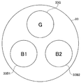
- FIG. 2 is a diagram illustrating an example of a configuration of a rotary filter provided in the light source device.
- the rotary filter 33 has a disk shape, and three openings are provided at equal angles in the circumferential direction, and filters 33G, 33B1, and 33B2 are attached to the three openings, respectively.
- the filter 33G has a green (G) wavelength band as a transmission band
- the filters 33B1 and 33B2 have a blue (B) wavelength band as a transmission band.
- a narrow band G illumination light of 530-550 nm centered at 540 nm is transmitted from the filter 33G, and for example, 400-430 nm centered at 415 nm is transmitted from the filter 33B1.
- N-band B illumination light (hereinafter referred to as B1 illumination light) is transmitted, and the filter 33B2 transmits, for example, 400-430 nm narrow-band B illumination light (hereinafter referred to as B2) centered on 415 nm, in the same manner as the filter 33B1.
- B1 illumination light 400-430 nm narrow-band B illumination light
- B2 illumination light transmitted through the filters 33B1 and 33B2 have the same wavelength band.
- the center of the rotary filter 33 is attached to a rotary shaft of a rotary motor (not shown) and is driven to rotate.
- An encoder (not shown) is attached to the rotation shaft of the rotation motor, and the rotation of the rotation motor, that is, the rotation of the rotation filter 33 can be detected by the encoder.
- the image processing apparatus 4 to be described later controls the rotation of the rotation motor so that the rotation speed of the rotation filter 33 is constant (not shown).
- the light source device 3 performs imaging on the subject using narrow-band illumination light. For this reason, the amount of illumination light tends to be insufficient as compared to the case of using broadband illumination light that is normally widely used.
- the transmission loss on the short wavelength B side tends to be larger due to the optical transmission characteristics of the light guide fiber 26, and the B illumination light is emitted when emitted from the illumination lens 23 of the tip 22 as illumination light. The amount of light tends to be small.
- two filters 33B1 and 33B2 having the same transmission characteristic are arranged in the circumferential direction of the rotary filter 33, and each time the rotary filter 33 is rotated once by using these two filters 33B1 and 33B2. Then, the B illumination light is irradiated twice on the same part of the subject to be observed, and the imaging is performed twice based on the B illumination light by the return light.
- the rotation filter 33 is rotated once in a 1.5 frame period, and imaging with B illumination light is performed twice. The brightness of the captured image (B captured image) based on the B illumination light is improved by combining the two captured images.
- imaging with the G illumination light is performed once and imaging with the B illumination light is performed twice in the 1.5 frame period will be described. It can be set.
- the B1 captured image based on the return light of the narrow-band B1 illumination light and the B2 captured image based on the return light of the B2 illumination light are temporally shifted images, and the image quality deteriorates by combining these images.
- the image quality deteriorates by combining these images.
- synthesis is not performed.
- a captured image with sufficient brightness cannot be obtained with only one of the narrow-band B1 illumination light and B2 illumination light
- a captured image based on the other B illumination light is synthesized according to the brightness. As a result, a captured image with sufficient brightness is obtained while image quality deterioration is suppressed.
- the image processing apparatus 4 performs brightness control in accordance with the operator's sense by obtaining the brightness of the captured image by color conversion matrix processing.
- the CCD 25 of the endoscope 2 outputs a G captured image based on the return light of the G illumination light as a G signal, and a B1 captured image based on the return light of the B1 illumination light as B1.
- a B2 captured image based on the return light of the B2 illumination light is output as a B2 signal. That is, the video signal output from the endoscope 2 includes these G signal, B1 signal, and B2 signal.
- the image processing apparatus 4 includes an analog processing unit 41, an A / D converter 42, a color balance processing unit 48, a digital processing unit 43, a synchronization control unit 40, a synchronization memory 40a, and a synthesis processing unit 45.
- the analog processing unit 41 performs predetermined analog signal processing such as amplification processing on the video signal from the endoscope 2 and outputs it to the A / D converter 42.
- the A / D converter 42 converts the output of the analog processing unit 41 into a digital video signal, and then outputs the digital video signal to the color balance processing unit 48.
- the color balance processing unit 48 outputs a correction coefficient determined according to an operation of a color balance adjustment switch (not shown) provided on the front panel of the image processing apparatus 4 as a digital video signal output from the A / D converter 42.
- the color balance adjustment is performed by multiplying each color signal (G signal, B1 signal, and B2 signal) included in the image signal, and the digital video signal subjected to the color balance adjustment is output to the digital processing unit 43.
- the digital processing unit 43 performs clip processing on the digital video signal output from the color balance processing unit 48 based on the clip luminance (clip level) Yc output from the brightness calculation processing unit 44, thereby performing the clip processing.
- the upper limit value of the luminance value in the digital video signal subjected to is limited to the luminance value Yc.
- the digital processing unit 43 separates the digital video signal subjected to the above-described clip processing into a G signal, a B1 signal, and a B2 signal, and outputs them to the synchronization control unit 40 and the brightness calculation processing unit 44.
- the synchronization control unit 40 stores the G signal, the B1 signal, and the B2 signal output from the digital processing unit 43 in the synchronization memory 40a that stores the R image, the G image, and the B image.
- the synchronization memory 40a stores, for example, 30 frames of G signal, B1 signal, and B2 signal, respectively. Then, the synchronization control unit 40 reads out the G signal, the B1 signal, and the B2 signal that minimize the color misregistration from the synchronization memory 40a and outputs the signals to the synthesis processing unit 45.
- the brightness calculation processing unit 44 calculates the brightness of the captured image in order every 0.5 frame based on the G signal, the B1 signal, and the B2 signal output from the digital processing unit 43.
- the same matrix processing as that performed at the time of display on the monitor 5 is performed to perform the brightness. I ask for it.
- the illumination by the G illumination light and the B1 illumination light is used as the master illumination that is always used for imaging, and the illumination by the G illumination light and the B2 illumination light is supplementarily used when the brightness of the image is dark. Use slave lighting.
- the brightness calculation processing unit 44 obtains the luminance Y1 by the master illumination using matrix processing by the matrix processing unit 52 based on the G signal and the B1 signal. In addition, in order to obtain the brightness of the captured image by the slave illumination, the brightness calculation processing unit 44 obtains the luminance Y2 by the slave illumination by using the matrix processing by the matrix processing unit 52 based on the G signal and the B2 signal. .
- FIG. 3 is a block diagram illustrating an example of a specific configuration of the brightness calculation processing unit.
- the average value calculation unit 50 calculates an SB1 signal, an SG signal, and an SB2 signal that are average values of signals corresponding to the R image, the G image, and the B image.
- the R image brightness calculation unit 51R, the G image brightness calculation unit 51G, and the B image brightness calculation unit 51B obtain the brightness based on the SB1 signal, the SG signal, and the SB2 signal, respectively.
- the B1 signal is used as the R image signal
- the G signal is used as the G image signal
- the B2 signal is used as the B image signal.
- the R image brightness calculation unit 51R, the G image brightness calculation unit 51G, and the B image brightness calculation unit 51B hold the SB1 signal, the SG signal, and the SB2 signal, and then send them to the matrix processing unit 52 as Rf, Gf, and Bf. Output.
- the matrix processing unit 52 applies Rf, Gf, and Bf output from the R image brightness calculation unit 51R, the G image brightness calculation unit 51G, and the B image brightness calculation unit 51B to the following formula (1). Matrix operation related to color conversion is performed. In this case, the matrix processing unit 52 performs matrix processing on each of the master illumination and the slave illumination by matrix calculation using the following mathematical formula (1). In the following formula (1), ⁇ , ⁇ , and ⁇ are matrix coefficients.
- the matrix processing unit 52 supplies output values Rm, Gm, and Bm obtained by matrix processing for master illumination or matrix processing for slave illumination to the luminance calculation unit 53.
- the G signal is supplied to the luminance calculation unit 53 as the output value Rm, the B signal as the output value Gm, and the B signal as the output value Bm.
- the luminance calculation unit 53 calculates the output value Rm (G signal), the output value Gm (B signal), and the output value Bm (B signal) supplied from the matrix processing unit 52 by applying the following equation (2). To obtain the luminance Y1 by the master illumination.
- the luminance calculation unit 53 applies, for example, the output value Rm (G signal), the output value Gm (B signal), and the output value Bm (B signal) supplied from the matrix processing unit 52 to the following equation (3).
- the luminance Y2 by the slave illumination is obtained.
- the brightness calculation processing unit 44 calculates the value of the composition ratio a by calculation using the following formula (4). And the values of the clip luminance Yc and the target luminance Ys are respectively set according to the obtained value of the composition ratio a.
- a matrix processing unit 46 which will be described later, generates RGB image signal components from a G captured image and a B captured image obtained by imaging using narrowband light by matrix processing (color conversion matrix processing).
- the matrix processing in the matrix processing unit 52 of the brightness calculation processing unit 44 is the same processing as the matrix processing in the matrix processing unit 46. That is, the matrix calculation by the brightness calculation processing unit 44 is for obtaining a signal corresponding to the RGB input of the monitor 5, and the brightness obtained by the brightness calculation processing unit 44 is the luminance of the image displayed on the monitor. This corresponds to the luminance, and corresponds to the brightness of the image felt when the operator observes the monitor 5.
- the brightness calculation processing unit 44 outputs the synthesis ratio a obtained through the calculation of the above formula (4) to the synthesis processing unit 45, and sets the clip luminance Yc set according to the value of the synthesis ratio a to the digital processing unit 43. Output to. In addition, the brightness calculation processing unit 44 outputs the target luminance Ys set according to the value of the combination ratio a and the difference value ⁇ Y1 to the dimming control unit 49.
- the dimming control unit 49 generates and outputs a dimming signal for adjusting the aperture amount of the aperture 34 based on the target luminance Ys and the difference value ⁇ Y1 output from the brightness calculation processing unit 44. Specifically, the dimming control unit 49, for example, sets the difference value ⁇ Y1 output from the brightness calculation processing unit 44 so as to approach the target luminance Ys output from the brightness calculation processing unit 44. A dimming signal for adjusting the aperture amount of the aperture 34 so as to approach 0 is generated and output. And the light quantity of G illumination light and the light quantity of B illumination light (B1 illumination light and B2 illumination light) are adjusted by control of such a light control control part 49.
- the composition processing unit 45 synthesizes the captured image by the master illumination and the captured image by the slave illumination based on the composition ratio a. That is, when the composition ratio a is 0, the composition processing unit 45 outputs a captured image by the master illumination from the digital processing unit 43, that is, a signal using only the G signal and the B1 signal to the matrix processing unit 46. In addition, when the combination ratio a is not 0, the combination processing unit 45 uses a signal based on the image captured by the master illumination as an image captured by the slave illumination, that is, a signal obtained by the G signal and the B2 signal and the combination ratio a. And synthesize.
- the following formula (5) is an arithmetic expression used when a captured image obtained by master illumination and a captured image obtained by slave illumination are combined based on the combination ratio a.
- Rin, Gin, and Bin in the following mathematical formula (5) indicate input of an R image, a G image, and a B image.
- the B2 signal from the synchronization control unit 40 is input to the synthesis processing unit 45 as Rin of the following formula (5)
- the G signal from the synchronization control unit 40 is input.
- the signal is input to the synthesis processing unit 45 as Gin of the following equation (5)
- the B1 signal from the synchronization control unit 40 is input to the synthesis processing unit 45 as Bin of the following equation (5).
- the synthesis processing unit 45 obtains a synthesized signal by performing an operation using the above formula (5), and outputs the obtained synthesized signal to the matrix processing unit 46.
- the matrix processing unit 46 obtains a signal corresponding to the RGB input of the monitor 5 by matrix processing.
- Equation (6) shows an example of matrix processing by the matrix processing unit 46.
- ⁇ , ⁇ , and ⁇ in the following formula (6) are matrix coefficients set to the same values as ⁇ , ⁇ , and ⁇ in the formula (1).
- Rout, Gout, and Bout in the following mathematical formula (6) indicate outputs of the R image, the G image, and the B image after the matrix processing.
- ⁇ , ⁇ and ⁇ can be changed according to the color tone desired for narrowband light observation. These are obtained in a range of 0.7 to 1.5, for example, and selected from a plurality of candidates so that they are neither too large nor too small. If this range is exceeded, noise increases or saturation tends to occur. Under this condition, only ⁇ is determined in the range of 0.35 to 0.75 in consideration of (1 + a) in the above equation (5). Of course, because of this consideration, there is no increase in noise or saturation, but it is necessary to expand the bit width so that the dynamic range is not lost.
- the D / A converter 47 converts the output of the matrix processing unit 46 into an analog signal and outputs it to the monitor 5. That is, Rout, Gout, and Bout in the equation (6) are given to the monitor 5 as RGB inputs.
- the monitor 5 displays a narrow band light observation image corresponding to the input RGB input.
- the surgeon When using the endoscope apparatus 1, the surgeon connects the connector 27 of the endoscope 2 to the light source apparatus 3 and the image processing apparatus 4 as shown in FIG. 1. Thereby, the connection state shown in FIG. 1 is obtained.
- the surgeon operates a power switch (not shown) so that the light source device 3, the image processing device 4, and the monitor 5 are in an operating state, and performs an operation for narrowband light observation.
- the light emitted from the light source 31 is converted into narrowband G illumination light, B1 illumination light, and B2 illumination light by the narrowband filter 32 and the rotary filter 33, and after adjusting the brightness by the diaphragm 34, Supplied to the mirror 2.
- Each illumination light is irradiated from the illumination lens 23 to the subject side through the light guide fiber 26 sequentially and substantially continuously, for example, in a period of 1/20 second.
- the CCD 25 captures an optical image by the return light from the part.
- the G signal, the B1 signal, and the B2 signal corresponding to the return lights of the G illumination light, the B1 illumination light, and the B2 illumination light are obtained by the photoelectric conversion of the CCD 25.
- Video signals including the G signal, the B1 signal, and the B2 signal are given from the endoscope 2 to the image processing device 4.
- the B1 signal and the B2 signal are signals obtained by imaging with the same exposure amount using illumination light in the same wavelength band, and are substantially the same under the same conditions except that there is a short timing shift within one frame. It is obtained by.
- the video signal input to the image processing device 4 is subjected to predetermined analog processing by the analog processing unit 41 and then converted to a digital signal by the A / D converter 42.
- the digital video signal from the A / D converter 42 is subjected to color balance adjustment by the color balance processing unit 48 and then input to the digital processing unit 43.
- the digital processing unit 43 subjects the digital video signal output from the color balance processing unit 48 to clip processing based on the clip luminance Yc output from the brightness calculation processing unit 44, and the digital video signal subjected to the clip processing. Is separated into a G signal, a B1 signal, and a B2 signal and output to the synchronization control unit 40 and the brightness calculation processing unit 44.
- the brightness calculation processing unit 44 calculates the luminance Y1 by the master illumination and the luminance Y2 by the slave illumination by the matrix processing in the matrix processing unit 52, respectively. Further, the brightness calculation processing unit 44 calculates a difference value ⁇ Y1 between the target luminance Ys and the luminance Y1, obtains a composition ratio a using the calculated difference value ⁇ Y1, and further determines the value of the obtained composition ratio a.
- the values of the clip luminance Yc and the target luminance Ys are respectively set according to.
- the target luminance Ys is set to a predetermined initial value Ydb at a timing immediately after the image processing device 4 is activated, and when the image processing device 4 is in an operating state. Is set as a value corresponding to the value of the composition ratio a. Specifically, for example, the target luminance Ys is set to the luminance Yt when the composition ratio a is 0 or more and less than the predetermined threshold value TH1, and when the composition ratio a is greater than or equal to the predetermined threshold value TH1 and 1 or less, for example.
- the luminance Yu is set larger than the luminance Yt.
- the target brightness Ys is not only set according to the value of the combination ratio a, but for example, the color balance adjustment by the color balance processing unit 48 is performed from the A / D converter 42.
- the brightness calculation processing unit 44 performs synthesis.
- the target luminance Ys may be set to the luminance Yw that is equal to or higher than the luminance Yu.
- the clip luminance Yc is set based on, for example, data defining the correlation between the composition ratio a and the clip luminance Yc as shown in FIG.
- FIG. 4 is a diagram illustrating an example of the correlation between the composition ratio a and the clip luminance Yc.
- the clip luminance Yc may be set based on data defining the correlation between the composition ratio a and the clip luminance Yc as shown in FIG.
- FIG. 5 is a diagram showing an example of the correlation between the composition ratio a and the clip luminance Yc, which is different from FIG.
- the value of Yc is set to increase within the range of 160 ⁇ Yc ⁇ 200 in proportion to the increase of the value of a. That is, according to FIG. 5, the composition ratio a and the clip luminance Yc have a proportional relationship within the range of 0 ⁇ a ⁇ 0.6 and 160 ⁇ Yc ⁇ 200.
- the brightness calculation processing unit 44 outputs the synthesis ratio a obtained as described above to the synthesis processing unit 45, and outputs the clip luminance Yc set as described above to the digital processing unit 43. Further, the brightness calculation processing unit 44 outputs the target luminance Ys set as described above and the difference value ⁇ Y1 to the dimming control unit 49.
- the dimming control unit 49 generates and outputs a dimming signal for adjusting the aperture amount of the aperture 34 based on the target luminance Ys and ⁇ Y1 output from the brightness calculation processing unit 44.
- the synthesis processing unit 45 obtains a synthesized signal by applying the synthesis ratio a output from the brightness calculation processing unit 44 to the formula (5), and outputs the obtained synthesized signal to the matrix processing unit 46.
- the composite signal output from the composite processing unit 45 is given to the matrix processing unit 46 and subjected to matrix processing, and R, G, and B image signals in the display system are obtained.
- the output of the matrix processing unit 46 is returned to an analog signal by the D / A converter 47 and then supplied to the monitor 5.
- the target luminance Ys and the clip luminance Yc can be set according to the value of the composition ratio a. Therefore, according to the present embodiment, for example, even when the pixel size of the CCD 25 is small (saturation level is low), it is possible to suppress deterioration in image quality due to variation in saturation level for each pixel. As a result, the image quality of the narrow-band light observation image can be improved as compared with the conventional case.
- a freeze image is displayed on the monitor 5.
- a composite signal that minimizes the value of the composite ratio a is selected from each composite signal stored in the memory and output to the matrix processing unit 46. Also good.
- a freeze image is displayed on the monitor 5.
- a composite signal in which the elapsed time from the instruction timing is equal to or less than a predetermined time and the value of the composite ratio a is equal to or less than a predetermined value is stored in the memory. You may make it select from a signal and make it output to the matrix process part 46.
- the setting of the peripheral device and the setting of the image processing device 4 are interlocked with each other. You may make it switch.
- information indicating the positional relationship between the center position of the objective lens 24 and the center position of the effective pixel area of the CCD 25 is stored in advance in a memory (not shown) provided in the endoscope 2.
- the position adjustment process may be performed such that the center position of the observation image displayed on the monitor 5 is matched with the center position of the objective lens 24 based on the information read from the memory.
- the color balance adjustment by the color balance processing unit 48 reduces the signal level of each color signal included in the digital video signal output from the A / D converter 42 (1).
- control for reducing the light amount of the light source 31 may be performed.
- a plurality of scope switches capable of giving various instructions according to the operation of the operator are provided in the endoscope 2 and the endoscope connected to the image processing device 4 is provided.
- instructions that can be executed by operating the plurality of scope switches may be appropriately assigned.
- the rotational speed of the rotary filter 33 when imaging a subject with rapid movement is increased compared to the rotational speed of the rotary filter 33 when imaging a subject with gentle movement.
- the color shift of the freeze image displayed on the monitor 5 may be reduced.
- a light source device provided with an LED that emits G illumination light, an LED that emits B1 illumination light, and an LED that emits B2 illumination light
- a light emission time capable of generating a narrow-band light observation image with brightness is set for each LED, and a narrow-band light observation image is displayed on the monitor 5 according to the set light emission time for each LED.
- the frame rate may be changed.
- the dimming control unit 49 for example, the target luminance Ys and ⁇ Y1 output from the brightness calculation processing unit 44, and the detection result of the light distribution state of the illumination light irradiated from the light guide fiber 26, , And may be configured to generate a dimming signal.
Landscapes
- Health & Medical Sciences (AREA)
- Life Sciences & Earth Sciences (AREA)
- Surgery (AREA)
- Engineering & Computer Science (AREA)
- Physics & Mathematics (AREA)
- Biomedical Technology (AREA)
- Animal Behavior & Ethology (AREA)
- Radiology & Medical Imaging (AREA)
- Optics & Photonics (AREA)
- Nuclear Medicine, Radiotherapy & Molecular Imaging (AREA)
- Biophysics (AREA)
- Heart & Thoracic Surgery (AREA)
- Medical Informatics (AREA)
- Molecular Biology (AREA)
- Pathology (AREA)
- General Health & Medical Sciences (AREA)
- Public Health (AREA)
- Veterinary Medicine (AREA)
- Signal Processing (AREA)
- General Physics & Mathematics (AREA)
- Theoretical Computer Science (AREA)
- Endoscopes (AREA)
Abstract
内視鏡装置は、所定時間内に第1の帯域の光を1回照明するとともに第2の帯域の光を複数回照明する照明部と、第1の帯域の光の照明に基づく第1の撮像信号及び第2の帯域の光の照明に基づく第2の撮像信号を出力する撮像部と、第1及び第2の撮像信号をクリップするクリップ処理部と、第2の帯域の照明光の照明回数に応じて第1及び第2の撮像信号を組み合わせることにより第1及び第2の明るさを算出する明るさ算出部と、明るさ目標値及び第1の明るさに応じた合成比率を算出する合成比率算出部と、合成比率に応じて第1及び第2の撮像信号を合成する合成処理部と、明るさ目標値及び差分値に基づいて照明光の光量を調整する調光制御部と、合成比率に応じてクリップレベル及び明るさ目標値を設定する設定部と、を有する。
Description
本発明は、狭帯域光観察に好適な内視鏡装置に関する。
医療用内視鏡は観察対象部位が生体の内部であるので、体内を照明する光源装置が必要である。光源装置が発生した照明光は、内視鏡の挿入部を挿通したライトガイドを介して撮像部のある先端部から観察対象組織に照射される。
内視鏡による観察としては、白色光等の可視光を用いた通常光観察が広く行われている。面順次式の内視鏡装置では、回転フィルタに白色光の光源を透過させることで、R、G及びBの3色の照明光を体腔内の組織に対して順次照射する。そして、R、G及びBの3色の照明光に対応する反射光画像を時分割に取得して、各反射光画像から通常光観察を行うためのカラー画像を生成する。
また、従来、照射光の波長特性を利用した種々の特殊光観察も行われている。例えば、国際公開番号WO2010/131620号には、特殊光観察として、狭帯域光観察を行うための面順次方式の撮像装置が開示されている。狭帯域光観察では、血管を高いコントラストで観察するために、血液に強く吸収され、かつ粘膜表層で強く反射・散乱される、という特長を併せ持つ光の利用に着目し、青色狭帯域光と緑色狭帯域光とを順次、生体組織に照射することにより、粘膜表層の毛細血管と深部の太い血管とのコントラストを強調表示する。
国際公開番号WO2010/131620号の発明では、緑色の狭帯域光Gと青色の2つの狭帯域光B1及びB2を順次照射可能に構成されている。国際公開番号WO2010/131620号の撮像装置では、狭帯域光G、B1及びB2に対応する反射光画像(狭帯域画像)から作成した狭帯域光観察画像を用いて狭帯域光観察を行うようになっている。また、国際公開番号WO2010/131620号の発明では、狭帯域光B1が照射された際に得られた画像と、狭帯域光B2が照射された際に得られた画像と、の加算に用いられる加算量が画像の平均の明るさに基づいて決定されている。
しかし、国際公開番号WO2010/131620号に開示された発明によれば、例えば、画素サイズが小さい(飽和レベルが低い)撮像素子を撮像部に搭載した場合において、当該撮像素子の画素毎の飽和レベルのばらつきに起因する狭帯域光観察画像の画質の低下が生じてしまう、という課題が生じている。
本発明は、前述した事情に鑑みてなされたものであり、狭帯域光観察画像の画質を従来に比べて向上させることが可能な内視鏡装置を提供することを目的としている。
本発明の一態様の内視鏡装置は、所定の時間内に、第1の帯域の照明光による照明を1回行うとともに、第2の帯域の照明光による照明をN回(N≧2の整数)行う照明部と、前記照明部により照明された被写体を撮像し、前記第1の帯域の照明光の照明に基づく第1の撮像信号及び前記第2の帯域の照明光の照明に基づく第2の撮像信号を出力する撮像部と、前記第1の撮像信号及び前記第2の撮像信号における輝度値の上限値を、クリップレベルに応じて制限する処理を行うクリップ処理部と、前記第1の帯域の照明光による照明に基づく第1の撮像信号とK回(1≦K<Nの整数)の照明に基づく第2の撮像信号とを用いた色変換マトリクス処理により第1の明るさを算出し、前記第1の帯域の照明光による照明に基づく第1の撮像信号とN-K回の照明に基づく第2の撮像信号とを用いた色変換マトリクス処理により第2の明るさを算出する明るさ算出部と、明るさ目標値と前記第1の明るさとの差分値に応じた合成比率を算出する合成比率算出部と、前記合成比率算出部により算出された前記合成比率を前記第2の明るさの元となる前記第1及び第2の撮像信号に対して乗算した後、前記第1の明るさの元となる前記第1及び第2の撮像信号に合成する合成処理部と、前記明るさ目標値及び前記差分値に基づいて前記照明部に対する制御を行うことにより、前記第1の帯域の照明光の光量と、前記第2の帯域の照明光の光量と、を調整する調光制御部と、前記合成比率算出部により算出された前記合成比率に応じて前記クリップレベル及び前記明るさ目標値を設定する設定部と、を有する。
以下、本発明の実施の形態について、図面を参照しつつ説明を行う。
図1から図5は、本発明の実施例に係るものである。図1は、本発明の実施例に係る内視鏡装置の構成を示すブロック図である。
図1に示すように、内視鏡装置1は、被検体としての生体の内部を観察するための内視鏡2と、生体の内部の観察を行うために狭帯域の照明光を照射する光源装置3と、狭帯域の照明光の下で撮像された撮像信号に対する信号処理を行う画像処理装置4とを備えている。画像処理装置4により生成された狭帯域画像はモニター5に供給されるようになっている。モニター5としては通常のカラーモニターを採用することができる。すなわち、モニター5は、RGB入力端子(図示省略)を備えており、RGB入力端子に、R画像、G画像及びB画像の信号が供給されてカラー表示を行う。
内視鏡2は、体腔内に挿入できる程度の外径を有する可撓性の挿入部21を有し、挿入部21の内部には、光源装置3から照射される光を導光するための、石英ファイバ等により構成されたライトガイドファイバ26が挿通されている。ライトガイドファイバ26の一端は、光源装置3に対して着脱自在に接続されるコネクタ27に接続される。ライトガイドファイバ26の他端は、挿入部21の先端の先端部22に設けられた照明レンズ23の近傍に配置されている。なお、コネクタ27は光源装置3に接続されると共に後述する画像処理装置4にも接続される。
光源装置3からの照明光は、ライトガイドファイバ26により挿入部21の先端部22に導かれ、照明レンズ23によって拡散されて被検体に照射される。また、先端部22には、被検体からの戻り光により被検体の光学像を結ぶための対物レンズ24と、その結像位置に配置された撮像素子としてのCCD(電荷結合素子)25とが設けられている。撮像手段を構成するCCD25は、画像処理装置4に設けられた図示しないCCD駆動回路によって駆動され(図示省略)、被検体を撮像し、撮像した被検体の光学像を映像信号に変換して、画像処理装置4に出力する。
光源装置3は、キセノンランプ等により構成される光源31を備える。光源31は、白色光に近い波長帯域の光を発光する。光源31の照射光路上には、狭帯域フィルタ32、回転フィルタ33及び絞り34が配設されている。
狭帯域フィルタ32は、光源31から発光される光の帯域を狭帯域にして回転フィルタ33に出射する。回転フィルタ33は狭帯域フィルタ32を通過した光の帯域を、狭帯域光観察に必要な波長帯域に制限する。絞り34は、回転フィルタ33を通過した光の光量を制限することにより、光量を調整する。絞り34は、後述する調光制御部49によって絞り量が制御されるようになっている。
図2は、光源装置に設けられた回転フィルタの構成の一例を示す図である。回転フィルタ33は、円板形状で、周方向には、3つの開口が等しい角度で設けられており、3つの開口には、夫々フィルタ33G、33B1、33B2が取り付けられている。フィルタ33Gは、緑(G)の波長帯域を透過帯域とし、フィルタ33B1、33B2は、青(B)の波長帯域を透過帯域としている。
狭帯域フィルタ32及び回転フィルタ33によって、フィルタ33Gからは、例えば、540nmを中心とした530-550nmの狭帯域のG照明光が透過し、フィルタ33B1からは、例えば415nmを中心とした400-430nmの狭帯域のB照明光(以下、B1照明光という)が透過し、フィルタ33B2からは、フィルタ33B1と同様に、例えば415nmを中心とした400-430nmの狭帯域のB照明光(以下、B2照明光という)が透過する。このように、フィルタ33B1、33B2を透過した狭帯域のB1照明光、B2照明光は、同じ波長帯域である。
この回転フィルタ33は、中心が図示しない回転用モータの回転軸に取り付けられて、回転駆動されるようになっている。回転用モータの回転軸等には、図示しないエンコーダが取り付けられており、エンコーダによって回転用モータの回転、すなわち、回転フィルタ33の回転が検出可能である。後述する画像処理装置4は、回転フィルタ33の回転速度が一定となるように、回転用モータの回転を制御するようになっている(図示省略)。
このように本実施例においては、光源装置3からは狭帯域の照明光を用いて、被検体に対する撮像を行う。このため、通常広く用いられる広帯域の照明光を用いた場合に比較すると、照明光量が不足しがちになることがある。特に、ライトガイドファイバ26による光学的伝送特性上から、短波長B側での伝送ロスがより大きくなる傾向があり、先端部22の照明レンズ23から照明光として出射する場合におけるB照明光の出射光量は小さくなりやすい。
そこで、本実施例においては、回転フィルタ33の周方向に同一透過特性のフィルタ33B1、33B2を2つ配置し、これらの2つのフィルタ33B1、33B2を用いて回転フィルタ33が1回転される毎に、観察対象となる被検体の同一部位にB照明光を2回照射し、その戻り光によりB照明光に基づく2回の撮像を行う。例えば、1.5フレーム期間に回転フィルタ33を1回転させ、B照明光による撮像を2回行う。そして、2回の撮像を合成することにより、B照明光に基づく撮像画像(B撮像画像)の明るさを向上させるようになっている。
なお、1.5フレーム期間にG照明光の照明による撮像を1回、B照明光の照明による撮像を2回行う例について説明するが、各色の狭帯域光による撮像を行う周期及び回数は適宜設定可能である。
しかしながら、狭帯域のB1照明光の戻り光に基づくB1撮像画像とB2照明光の戻り光に基づくB2撮像画像は時間的にずれた画像であり、これらの画像を合成することによって画質が劣化する虞がある。そこで、本実施例においては、狭帯域のB1照明光、B2照明光の一方の光のみによって十分な明るさの撮像画像が得られる場合には合成を行わない。また、狭帯域のB1照明光、B2照明光の一方の光のみでは十分な明るさの撮像画像が得られない場合には、明るさに応じて他方のB照明光に基づく撮像画像を合成することにより、画質劣化を抑制しながら、十分な明るさの撮像画像を得るようにしている。
この場合において、本実施例においては、画像処理装置4は、色変換マトリクス処理によって撮像画像の明るさを求めることにより、術者の感覚に応じた明るさ制御を行うようになっている。
一方、以上に述べた構成によれば、内視鏡2のCCD25は、G照明光の戻り光に基づくG撮像画像をG信号として出力し、B1照明光の戻り光に基づくB1撮像画像をB1信号として出力し、B2照明光の戻り光に基づくB2撮像画像をB2信号として出力する。すなわち、内視鏡2から出力される映像信号には、これらのG信号、B1信号及びB2信号が含まれている。
画像処理装置4は、アナログ処理部41と、A/D変換器42と、カラーバランス処理部48と、デジタル処理部43と、同時化制御部40と、同時化メモリ40aと、合成処理部45と、マトリクス処理部46と、D/A変換器47と、明るさ算出処理部44と、調光制御部49と、を有している。
アナログ処理部41は、内視鏡2からの映像信号に対して増幅処理等の所定のアナログ信号処理を施してA/D変換器42に出力する。
A/D変換器42は、アナログ処理部41の出力をデジタル映像信号に変換した後、カラーバランス処理部48へ出力する。
カラーバランス処理部48は、画像処理装置4のフロントパネルに設けられたカラーバランス調整スイッチ(図示省略)の操作に応じて決定した補正係数を、A/D変換器42から出力されるデジタル映像信号に含まれる各色信号(G信号、B1信号及びB2信号)に乗ずることによりカラーバランス調整を行い、当該カラーバランス調整を施したデジタル映像信号をデジタル処理部43へ出力する。
デジタル処理部43は、カラーバランス処理部48から出力されるデジタル映像信号に対し、明るさ算出処理部44から出力されるクリップ輝度(クリップレベル)Ycに基づくクリップ処理を施すことにより、当該クリップ処理を施したデジタル映像信号における輝度値の上限値を輝度値Ycに制限する。また、デジタル処理部43は、前述のクリップ処理を施したデジタル映像信号をG信号、B1信号及びB2信号に分離して同時化制御部40及び明るさ算出処理部44へ出力する。
同時化制御部40は、デジタル処理部43から出力されるG信号、B1信号及びB2信号を、R画像、G画像及びB画像を記憶する同時化メモリ40aに記憶させる。なお、同時化メモリ40aには、例えば夫々30フレーム分のG信号、B1信号及びB2信号が記憶される。そして、同時化制御部40は、色ズレが最小となるようなG信号、B1信号及びB2信号を同時化メモリ40aから読み出して合成処理部45へ出力する。
明るさ算出処理部44は、デジタル処理部43から出力されるG信号、B1信号及びB2信号に基づき、0.5フレーム毎に順番に撮像画像の明るさを算出する。本実施例においては、撮像画像の明るさをモニター5に実際に表示させた場合の明るさで評価するために、モニター5への表示に際して行われるマトリクス処理と同様のマトリクス処理を実施して明るさを求める。更に、本実施例においては、G照明光及びB1照明光による照明を、撮像に必ず用いるマスター照明とし、G照明光及びB2照明光による照明を、画像の明るさが暗い場合に補助的に用いるスレーブ照明とする。マスター照明による撮像画像の明るさを求めるために、明るさ算出処理部44は、G信号及びB1信号に基づいて、マトリクス処理部52によるマトリクス処理を利用してマスター照明による輝度Y1を求める。また、スレーブ照明による撮像画像の明るさを求めるために、明るさ算出処理部44は、G信号及びB2信号に基づいて、マトリクス処理部52によりマトリクス処理を利用してスレーブ照明による輝度Y2を求める。図3は、明るさ算出処理部の具体的な構成の一例を示すブロック図である。
平均値算出部50は、R画像、G画像、B画像に相当する信号の平均値であるSB1信号、SG信号及びSB2信号を算出する。
R画像明るさ算出部51R、G画像明るさ算出部51G及びB画像明るさ算出部51Bは、SB1信号、SG信号及びSB2信号によって、それぞれ明るさを求める。なお、本実施例においては、R画像の信号としてB1信号が用いられ、G画像の信号としてG信号が用いられ、B画像の信号としてB2信号が用いられる。
R画像明るさ算出部51R、G画像明るさ算出部51G及びB画像明るさ算出部51Bは、SB1信号、SG信号及びSB2信号を保持してから、Rf、Gf及びBfとしてマトリクス処理部52へ出力する。
マトリクス処理部52は、R画像明るさ算出部51R、G画像明るさ算出部51G及びB画像明るさ算出部51Bから出力されるRf、Gf及びBfを下記数式(1)に適用することにより、色変換に係るマトリクス演算を行う。この場合には、マトリクス処理部52は、下記数式(1)を用いたマトリクス演算によって、マスター照明及びスレーブ照明の夫々に対してマトリクス処理を行う。なお、下記数式(1)のα、β及びγは、マトリクス係数である。

マトリクス処理部52は、マスター照明に対するマトリクス処理またはスレーブ照明に対するマトリクス処理によって得られた出力値Rm、Gm及びBmを輝度算出部53へ供給する。なお、本実施例においては、出力値RmとしてG信号が、出力値GmとしてB信号が、出力値BmとしてB信号が輝度算出部53に供給される。
輝度算出部53は、例えば、マトリクス処理部52から供給された出力値Rm(G信号)、出力値Gm(B信号)及び出力値Bm(B信号)を下記数式(2)に適用して演算を行うことにより、マスター照明による輝度Y1を求める。
Y1=0.3Rm+0.59Gm+0.11Bm
=0.3(α・SG)+0.59(β・SB1)+0.11(γ・SB1) …(2)
また、輝度算出部53は、例えば、マトリクス処理部52から供給された出力値Rm(G信号)、出力値Gm(B信号)及び出力値Bm(B信号)を下記数式(3)に適用して演算を行うことにより、スレーブ照明による輝度Y2を求める。
=0.3(α・SG)+0.59(β・SB1)+0.11(γ・SB1) …(2)
また、輝度算出部53は、例えば、マトリクス処理部52から供給された出力値Rm(G信号)、出力値Gm(B信号)及び出力値Bm(B信号)を下記数式(3)に適用して演算を行うことにより、スレーブ照明による輝度Y2を求める。
Y2=0.3Rm+0.59Gm+0.11Bm
=0.3(α・SG)+0.59(β・SB2)+0.11(γ・SB2) …(3)
明るさ算出処理部44は、目標輝度(明るさ目標値)Ysと輝度Y1との差(Ys-Y1)=ΔY1を求める。そして、明るさ算出処理部44は、ΔY1≦0の場合、すなわち、マスター照明のみによって目標とする明るさが得られている場合には、スレーブ照明による撮像画像の合成比率a(0≦a≦1)の値を0に設定するとともに、クリップ輝度Yc及び目標輝度Ysの値をそれぞれ所定値に設定する。一方、明るさ算出処理部44は、ΔY1>0の場合、すなわち、マスター照明のみでは目標とする明るさが得られない場合には、下記数式(4)を用いた演算により合成比率aの値を求めるとともに、当該求めた合成比率aの値に応じてクリップ輝度Yc及び目標輝度Ysの値をそれぞれ設定する。
ΔY1=Y2×a a=ΔY1/Y2 …(4)
狭帯域光観察においては、狭帯域のG照明光及びB照明光の各戻り光に基づく撮像画像を用いる。後述するマトリクス処理部46は、狭帯域光を用いた撮像によって得たG撮像画像及びB撮像画像からRGB画像の信号成分をマトリクス処理(色変換マトリクス処理)によって生成する。
狭帯域光観察においては、狭帯域のG照明光及びB照明光の各戻り光に基づく撮像画像を用いる。後述するマトリクス処理部46は、狭帯域光を用いた撮像によって得たG撮像画像及びB撮像画像からRGB画像の信号成分をマトリクス処理(色変換マトリクス処理)によって生成する。
明るさ算出処理部44のマトリクス処理部52におけるマトリクス処理は、マトリクス処理部46におけるマトリクス処理と同様の処理である。すなわち、明るさ算出処理部44によるマトリクス演算は、モニター5のRGB入力に対応した信号を得るためのものであり、明るさ算出処理部44によって得られる輝度は、モニター上に表示される画像の輝度に対応したものであって、術者がモニター5を観察した場合に感じられる画像の明るさに対応するものである。
なお、輝度算出部53の演算に用いられる上記数式(2)及び(3)の係数は、モニター5に表示する狭帯域光観察画像として希望する色調に応じて、変更可能であることは明らかである。
明るさ算出処理部44は、上記数式(4)の演算を経て得られた合成比率aを合成処理部45に出力し、合成比率aの値に応じて設定したクリップ輝度Ycをデジタル処理部43へ出力する。また、明るさ算出処理部44は、合成比率aの値に応じて設定した目標輝度Ysと、差分値ΔY1と、を調光制御部49へ出力する。
調光制御部49は、明るさ算出処理部44から出力される目標輝度Ys及び差分値ΔY1に基づき、絞り34の絞り量を調整するための調光信号を生成して出力する。具体的には、調光制御部49は、例えば、明るさ算出処理部44から出力される目標輝度Ysに近づけるように、すなわち、明るさ算出処理部44から出力される差分値ΔY1の値を0に近づけるように絞り34の絞り量を調整するための調光信号を生成して出力する。そして、このような調光制御部49の制御により、G照明光の光量と、B照明光(B1照明光及びB2照明光)の光量と、が調整される。
合成処理部45は、マスター照明による撮像画像とスレーブ照明による撮像画像とを、合成比率aに基づいて合成する。すなわち、合成処理部45は、合成比率aが0の場合には、デジタル処理部43からマスター照明による撮像画像、すなわち、G信号及びB1信号のみを用いた信号をマトリクス処理部46に出力する。また、合成処理部45は、合成比率aが0でない場合には、スレーブ照明による撮像画像、すなわち、G信号及びB2信号と合成比率aとによって得た信号を、マスター照明による撮像画像に基づく信号と合成する。
また、例えば、G照明光の明るさがB照明光よりも極めて明るい場合、すなわち、合成比率aの値が1になった場合には、電気的に余剰な乗算が無くノイズの増加を抑えられる。
下記数式(5)は、マスター照明による撮像画像とスレーブ照明による撮像画像とを、合成比率aに基づいて合成する際に用いられる演算式である。
なお、下記数式(5)のRin、Gin及びBinは、R画像、G画像及びB画像の入力を示している。具体的には、本実施例の狭帯域光観察においては、同時化制御部40からのB2信号が下記数式(5)のRinとして合成処理部45に入力され、同時化制御部40からのG信号が下記数式(5)のGinとして合成処理部45に入力され、同時化制御部40からのB1信号が下記数式(5)のBinとして合成処理部45に入力される。また、下記数式(5)のRt、Gt及びBtは、合成信号のR画像、G画像及びB画像の出力を示している。なお、下記数式(5)においては、Rt=B2として示されているが、後述するマトリクス処理により、モニター5に供給されるR画像の出力は略0となる。

合成処理部45は、上記数式(5)を用いた演算を行うことにより合成信号を求め、当該求めた合成信号をマトリクス処理部46に出力する。
マトリクス処理部46は、マトリクス処理によって、モニター5のRGB入力に対応した信号を得る。下記数式(6)は、マトリクス処理部46によるマトリクス処理の一例を示している。なお、下記数式(6)のα、β及びγは、上記数式(1)のα、β及びγと同一の値に設定されるマトリクス係数である。また、下記数式(6)のRout、Gout及びBoutは、マトリクス処理後のR画像、G画像、B画像の出力を示している。
α、β及びγは、狭帯域光観察として希望する色調に応じて変更できる。これらは、大き過ぎず小さ過ぎないように、例えば、0.7~1.5の範囲で求めておき、複数の候補から選択する。この範囲を超えてしまうと、ノイズが増えたり、飽和しやすくなる。この条件の下で、αだけは上記(5)式の(1+a)を考慮し、0.35~0.75の範囲で決めておく。当然、この考慮があるので、ノイズ増加や飽和増加は無いが、ダイナミックレンジが欠落しないようビット幅の拡張は必要である。

上記数式(6)においては、Rtに対して0が乗算される。そのため、上記数式(5)でRt=B2と示されているが、Rt=0でも構わない。
D/A変換器47は、マトリクス処理部46の出力をアナログ信号に変換してモニター5に出力する。すなわち、(6)式のRout、Gout、Boutが、RGB入力としてモニター5に与えられる。モニター5は、入力されたRGB入力に応じた狭帯域光観察画像を表示する。
次に、以上に述べたような構成を具備する本実施例の内視鏡装置1の作用について説明する。
術者は、内視鏡装置1を使用する際には、図1に示すように、内視鏡2のコネクタ27を光源装置3及び画像処理装置4に接続する。これにより、図1に示す接続状態が得られる。術者は、図示しない電源スイッチを操作して光源装置3、画像処理装置4、モニター5それぞれを動作状態として、狭帯域光観察のための操作を行う。
光源31から照射される光は、狭帯域フィルタ32及び回転フィルタ33によって、狭帯域のG照明光、B1照明光及びB2照明光に変換され、絞り34によって明るさが調整された後、内視鏡2に供給される。各照明光は、ライトガイドファイバ26を介して、例えば、1/20秒の周期において順次かつ略連続的に照明レンズ23から被検体側に照射される。
G照明光、B1照明光及びB2照明光が被検体の同一の部位に対して照射されたそれぞれのタイミングにおいて、CCD25は、その部位からの戻り光による光学像を撮像する。CCD25の光電変換によって、G照明光、B1照明光及びB2照明光の夫々の戻り光に対応したG信号、B1信号及びB2信号が得られる。G信号、B1信号及びB2信号を含む映像信号は、内視鏡2から画像処理装置4に与えられる。
なお、B1信号及びB2信号は、同一波長帯域の照明光を用いて同一の露光量で撮像されて得られる信号であり、1フレーム内で短いタイミングずれがあることを除けば、略同一の条件で得られるものである。
画像処理装置4に入力された映像信号は、アナログ処理部41によって所定のアナログ処理が施された後、A/D変換器42によってデジタル信号に変換される。A/D変換器42からのデジタル映像信号は、カラーバランス処理部48によるカラーバランス調整が施された後、デジタル処理部43に入力される。
デジタル処理部43は、カラーバランス処理部48から出力されるデジタル映像信号に対し、明るさ算出処理部44から出力されるクリップ輝度Ycに基づくクリップ処理を施し、当該クリップ処理を施したデジタル映像信号をG信号、B1信号及びB2信号に分離して同時化制御部40及び明るさ算出処理部44へ出力する。
明るさ算出処理部44は、マトリクス処理部52におけるマトリクス処理により、マスター照明による輝度Y1とスレーブ照明による輝度Y2とをそれぞれ算出する。また、明るさ算出処理部44は、目標輝度Ysと輝度Y1との差分値ΔY1を算出し、当該算出した差分値ΔY1を用いて合成比率aを求め、さらに、当該求めた合成比率aの値に応じてクリップ輝度Yc及び目標輝度Ysの値をそれぞれ設定する。
ここで、本実施例によれば、目標輝度Ysは、画像処理装置4が起動した直後のタイミングにおいては、所定の初期値Ydbに設定され、また、画像処理装置4が動作状態にある場合においては、合成比率aの値に応じた値として設定される。具体的には、目標輝度Ysは、例えば、合成比率aが0以上かつ所定の閾値TH1未満の場合には輝度Ytに設定され、合成比率aが所定の閾値TH1以上かつ1以下の場合には輝度Ytより大きな輝度Yuに設定される。
なお、本実施例によれば、合成比率aの値のみに応じて目標輝度Ysが設定されるものに限らず、例えば、カラーバランス処理部48によるカラーバランス調整が、A/D変換器42から出力されるデジタル映像信号に含まれる各色信号の信号レベルを減少させるような(1.0未満の)補正係数を用いて行われたことを検出した場合において、明るさ算出処理部44は、合成比率aの値にかかわらず、目標輝度Ysを輝度Yu以上の輝度Ywに設定するようにしてもよい。
一方、本実施例によれば、クリップ輝度Ycは、画像処理装置4が起動した直後のタイミングにおいては、所定の初期値Ydc(例えばYdc=200)に設定され、また、画像処理装置4が動作状態にある場合においては、合成比率aの値に応じた値として設定される。具体的には、クリップ輝度Ycは、例えば、合成比率aとクリップ輝度Ycとの間の相関を図4のように規定したデータに基づいて設定される。図4は、合成比率aとクリップ輝度Ycとの間の相関の一例を示す図である。
図4によれば、a=0の場合にはクリップ輝度Yc=160に設定され、a=1の場合にはクリップ輝度Yc=200に設定され、さらに、0<a<1の場合にはaの値の増加に比例して160<Yc<200の範囲内でYcの値が増加するように設定される。すなわち、図4によれば、0≦a≦1かつ160≦Yc≦200の範囲内において、合成比率aとクリップ輝度Ycとが比例関係を有している。
なお、本実施例によれば、クリップ輝度Ycは、合成比率aとクリップ輝度Ycとの間の相関を図5のように規定したデータに基づいて設定されるものであってもよい。図5は、合成比率aとクリップ輝度Ycとの間の相関の、図4とは異なる例を示す図である。
図5によれば、a=0の場合にはクリップ輝度Yc=160に設定され、0.6≦a≦1の場合にはクリップ輝度Yc=200に設定され、0<a<0.6の場合にはaの値の増加に比例して160<Yc<200の範囲内でYcの値が増加するように設定される。すなわち、図5によれば、0≦a≦0.6かつ160≦Yc≦200の範囲内において、合成比率aとクリップ輝度Ycとが比例関係を有している。
明るさ算出処理部44は、前述のように求めた合成比率aを合成処理部45に出力し、前述のように設定したクリップ輝度Ycをデジタル処理部43へ出力する。また、明るさ算出処理部44は、前述のように設定した目標輝度Ysと、差分値ΔY1と、を調光制御部49へ出力する。
調光制御部49は、明るさ算出処理部44から出力される目標輝度Ys及びΔY1に基づき、絞り34の絞り量を調整するための調光信号を生成して出力する。
合成処理部45は、明るさ算出処理部44から出力される合成比率aを上記数式(5)に適用することにより合成信号を求め、当該求めた合成信号をマトリクス処理部46に出力する。
合成処理部45から出力された合成信号は、マトリクス処理部46に与えられてマトリクス処理され、表示系におけるR画像、G画像及びB画像の信号が得られる。マトリクス処理部46の出力はD/A変換器47によってアナログ信号に戻された後、モニター5に供給される。
以上に述べたように、本実施例によれば、合成比率aの値に応じた目標輝度Ys及びクリップ輝度Ycを設定することができる。そのため、本実施例によれば、例えば、CCD25の画素サイズが小さい(飽和レベルが低い)場合であっても、画素毎の飽和レベルのばらつきに起因する画質の低下を抑制することができ、その結果、狭帯域光観察画像の画質を従来に比べて向上させることができる。
なお、本実施例によれば、例えば、合成処理部45から出力された合成信号を複数フレーム分蓄積可能なフレームメモリ(図示省略)を画像処理装置4に設けることにより、モニター5にフリーズ画像を表示させるための指示が行われた際に、合成比率aの値が最小となる合成信号を、当該メモリに蓄積された各合成信号の中から選択してマトリクス処理部46に出力させるようにしてもよい。
また、本実施例によれば、例えば、合成処理部45から出力された合成信号を複数フレーム分蓄積可能なフレームメモリ(図示省略)を画像処理装置4に設けることにより、モニター5にフリーズ画像を表示させるための指示が行われた際に、当該指示のタイミングからの経過時間が所定時間以下であるとともに、合成比率aの値が所定値以下となる合成信号を、当該メモリに蓄積された合成信号の中から選択してマトリクス処理部46に出力させるようにしてもよい。
また、本実施例によれば、例えば、画像ファイリング装置等の周辺機器が画像処理装置4に接続された際に、当該周辺機器の設定と当該画像処理装置4の設定とが相互に連動して切り替えられるようにしてもよい。
また、本実施例によれば、例えば、対物レンズ24の中心位置とCCD25の有効画素領域の中心位置との位置関係を示す情報が、内視鏡2に設けられたメモリ(図示省略)に予め格納されるとともに、当該メモリから読み込んだ当該情報に基づき、モニター5に表示させる観察画像の中心位置を対物レンズ24の中心位置に合わせるような位置調整処理が行われるようにしてもよい。
また、本実施例によれば、例えば、カラーバランス処理部48によるカラーバランス調整が、A/D変換器42から出力されるデジタル映像信号に含まれる各色信号の信号レベルを減少させるような(1.0未満の)補正係数を用いて行われた場合において、光源31の光量を低下させるための制御が行われるようにしてもよい。
また、本実施例によれば、例えば、術者の操作に応じた種々の指示が可能な複数のスコープスイッチ(図示省略)を内視鏡2に設けるとともに、画像処理装置4に接続された内視鏡2において使用可能な機能を検出した結果に応じ、当該複数のスコープスイッチの操作により実施可能な指示を適宜割り当てるようにしてもよい。
また、本実施例によれば、例えば、動きの激しい被写体を撮像する場合における回転フィルタ33の回転速度を、動きの穏やかな被写体を撮像する場合における回転フィルタ33の回転速度に比べて高速化することにより、モニター5に表示されるフリーズ画像の色ずれを軽減するようにしてもよい。
また、本実施例によれば、例えば、G照明光を発するLEDと、B1照明光を発するLEDと、B2照明光を発するLEDと、を設けた光源装置を使用する場合において、観察に適した明るさの狭帯域光観察画像を生成することが可能な発光時間が各LED毎に設定されるとともに、当該設定された各LED毎の発光時間に応じて狭帯域光観察画像をモニター5に表示する際のフレームレートが変化するようにしてもよい。
また、本実施例によれば、例えば、光源31の駆動電流(ランプ電流)を増加または減少させることにより、光源装置3から照射される光の光量を、絞り34の絞り量で調整可能な範囲外の光量に調整するようにしてもよい。
また、本実施例の調光制御部49は、例えば、明るさ算出処理部44から出力される目標輝度Ys及びΔY1と、ライトガイドファイバ26から照射される照明光の配光状態の検出結果と、に基づいて調光信号を生成するように構成されていてもよい。
本発明は、上述した実施例に限定されるものではなく、発明の趣旨を逸脱しない範囲内において種々の変更や応用が可能であることは勿論である。
本出願は、2013年3月25日に日本国に出願された特願2013-62433号を優先権主張の基礎として出願するものであり、上記の開示内容は、本願明細書、請求の範囲、図面に引用されたものとする。
Claims (5)
- 所定の時間内に、第1の帯域の照明光による照明を1回行うとともに、第2の帯域の照明光による照明をN回(N≧2の整数)行う照明部と、
前記照明部により照明された被写体を撮像し、前記第1の帯域の照明光の照明に基づく第1の撮像信号及び前記第2の帯域の照明光の照明に基づく第2の撮像信号を出力する撮像部と、
前記第1の撮像信号及び前記第2の撮像信号における輝度値の上限値を、クリップレベルに応じて制限する処理を行うクリップ処理部と、
前記第1の帯域の照明光による照明に基づく第1の撮像信号とK回(1≦K<Nの整数)の照明に基づく第2の撮像信号とを用いた色変換マトリクス処理により第1の明るさを算出し、前記第1の帯域の照明光による照明に基づく第1の撮像信号とN-K回の照明に基づく第2の撮像信号とを用いた色変換マトリクス処理により第2の明るさを算出する明るさ算出部と、
明るさ目標値と前記第1の明るさとの差分値に応じた合成比率を算出する合成比率算出部と、
前記合成比率算出部により算出された前記合成比率を前記第2の明るさの元となる前記第1及び第2の撮像信号に対して乗算した後、前記第1の明るさの元となる前記第1及び第2の撮像信号に合成する合成処理部と、
前記明るさ目標値及び前記差分値に基づいて前記照明部に対する制御を行うことにより、前記第1の帯域の照明光の光量と、前記第2の帯域の照明光の光量と、を調整する調光制御部と、
前記合成比率算出部により算出された前記合成比率に応じて前記クリップレベル及び前記明るさ目標値を設定する設定部と、
を有することを特徴とする内視鏡装置。 - 前記設定部は、前記合成比率の増加に比例して、前記クリップレベルを所定の範囲内において増加させるように設定する
ことを特徴とする請求項1に記載の内視鏡装置。 - 前記設定部は、前記合成比率が0以上かつ所定の閾値未満の場合には、前記明るさ目標値を第1の値に設定し、前記合成比率が前記所定の閾値以上かつ1以下の場合には、前記明るさ目標値を、前記第1の値より大きな第2の値に設定する
ことを特徴とする請求項1に記載の内視鏡装置。 - 前記クリップ処理部の前段において、前記第1の撮像信号及び前記第2の撮像信号に対してカラーバランス調整を施すカラーバランス処理部をさらに有し、
前記設定部は、前記カラーバランス処理部のカラーバランス調整により、前記第1の撮像信号及び前記第2の撮像信号のうちの少なくとも一方の撮像信号の信号レベルが減少したことを検出した場合においては、前記合成比率にかかわらず、前記明るさ目標値を前記第2の値以上の第3の値に設定する
ことを特徴とする請求項3に記載の内視鏡装置。 - N=2かつK=1である
ことを特徴とする請求項1に記載の内視鏡装置。
Priority Applications (4)
| Application Number | Priority Date | Filing Date | Title |
|---|---|---|---|
| EP14774577.2A EP2942001A4 (en) | 2013-03-25 | 2014-01-23 | ENDOSCOPY DEVICE |
| CN201480005323.8A CN104936503B (zh) | 2013-03-25 | 2014-01-23 | 内窥镜装置 |
| JP2014532177A JP5747362B2 (ja) | 2013-03-25 | 2014-01-23 | 内視鏡装置 |
| US14/804,554 US9545193B2 (en) | 2013-03-25 | 2015-07-21 | Endoscope apparatus |
Applications Claiming Priority (2)
| Application Number | Priority Date | Filing Date | Title |
|---|---|---|---|
| JP2013062433 | 2013-03-25 | ||
| JP2013-062433 | 2013-03-25 |
Related Child Applications (1)
| Application Number | Title | Priority Date | Filing Date |
|---|---|---|---|
| US14/804,554 Continuation US9545193B2 (en) | 2013-03-25 | 2015-07-21 | Endoscope apparatus |
Publications (1)
| Publication Number | Publication Date |
|---|---|
| WO2014156253A1 true WO2014156253A1 (ja) | 2014-10-02 |
Family
ID=51623256
Family Applications (1)
| Application Number | Title | Priority Date | Filing Date |
|---|---|---|---|
| PCT/JP2014/051368 WO2014156253A1 (ja) | 2013-03-25 | 2014-01-23 | 内視鏡装置 |
Country Status (5)
| Country | Link |
|---|---|
| US (1) | US9545193B2 (ja) |
| EP (1) | EP2942001A4 (ja) |
| JP (1) | JP5747362B2 (ja) |
| CN (1) | CN104936503B (ja) |
| WO (1) | WO2014156253A1 (ja) |
Cited By (1)
| Publication number | Priority date | Publication date | Assignee | Title |
|---|---|---|---|---|
| WO2024079785A1 (ja) * | 2022-10-11 | 2024-04-18 | オリンパスメディカルシステムズ株式会社 | 内視鏡システム、画像生成装置および画像生成方法 |
Families Citing this family (4)
| Publication number | Priority date | Publication date | Assignee | Title |
|---|---|---|---|---|
| JP6152635B2 (ja) * | 2012-11-08 | 2017-06-28 | ソニー株式会社 | 画像処理装置および方法、並びに、プログラム |
| CN104166258B (zh) * | 2014-08-18 | 2017-02-15 | 深圳市华星光电技术有限公司 | 液晶面板的灰阶值设定方法以及液晶显示器 |
| JP6732029B2 (ja) * | 2016-09-01 | 2020-07-29 | Hoya株式会社 | 電子スコープ及び電子内視鏡システム |
| CN110383828B (zh) * | 2017-03-09 | 2022-02-08 | 索尼公司 | 图像处理设备和方法 |
Citations (3)
| Publication number | Priority date | Publication date | Assignee | Title |
|---|---|---|---|---|
| WO2010131620A1 (ja) | 2009-05-14 | 2010-11-18 | オリンパスメディカルシステムズ株式会社 | 撮像装置 |
| JP2010279454A (ja) * | 2009-06-03 | 2010-12-16 | Olympus Corp | 画像処理装置、画像処理方法、画像処理プログラムおよび撮像装置 |
| WO2013031701A1 (ja) * | 2011-08-26 | 2013-03-07 | オリンパスメディカルシステムズ株式会社 | 内視鏡装置 |
Family Cites Families (7)
| Publication number | Priority date | Publication date | Assignee | Title |
|---|---|---|---|---|
| JP4270634B2 (ja) * | 1999-03-18 | 2009-06-03 | オリンパス株式会社 | 内視鏡装置 |
| US7892169B2 (en) * | 2000-07-21 | 2011-02-22 | Olympus Corporation | Endoscope apparatus |
| US6826424B1 (en) * | 2000-12-19 | 2004-11-30 | Haishan Zeng | Methods and apparatus for fluorescence and reflectance imaging and spectroscopy and for contemporaneous measurements of electromagnetic radiation with multiple measuring devices |
| JP4009626B2 (ja) * | 2004-08-30 | 2007-11-21 | オリンパス株式会社 | 内視鏡用映像信号処理装置 |
| JP5191090B2 (ja) * | 2005-07-15 | 2013-04-24 | オリンパスメディカルシステムズ株式会社 | 内視鏡装置 |
| JP5081720B2 (ja) * | 2008-05-22 | 2012-11-28 | 富士フイルム株式会社 | 蛍光内視鏡装置および励起光ユニット |
| CN102740760B (zh) * | 2010-06-28 | 2015-05-20 | 奥林巴斯医疗株式会社 | 内窥镜装置 |
-
2014
- 2014-01-23 JP JP2014532177A patent/JP5747362B2/ja active Active
- 2014-01-23 WO PCT/JP2014/051368 patent/WO2014156253A1/ja active Application Filing
- 2014-01-23 EP EP14774577.2A patent/EP2942001A4/en not_active Withdrawn
- 2014-01-23 CN CN201480005323.8A patent/CN104936503B/zh active Active
-
2015
- 2015-07-21 US US14/804,554 patent/US9545193B2/en active Active
Patent Citations (3)
| Publication number | Priority date | Publication date | Assignee | Title |
|---|---|---|---|---|
| WO2010131620A1 (ja) | 2009-05-14 | 2010-11-18 | オリンパスメディカルシステムズ株式会社 | 撮像装置 |
| JP2010279454A (ja) * | 2009-06-03 | 2010-12-16 | Olympus Corp | 画像処理装置、画像処理方法、画像処理プログラムおよび撮像装置 |
| WO2013031701A1 (ja) * | 2011-08-26 | 2013-03-07 | オリンパスメディカルシステムズ株式会社 | 内視鏡装置 |
Non-Patent Citations (1)
| Title |
|---|
| See also references of EP2942001A4 |
Cited By (1)
| Publication number | Priority date | Publication date | Assignee | Title |
|---|---|---|---|---|
| WO2024079785A1 (ja) * | 2022-10-11 | 2024-04-18 | オリンパスメディカルシステムズ株式会社 | 内視鏡システム、画像生成装置および画像生成方法 |
Also Published As
| Publication number | Publication date |
|---|---|
| EP2942001A1 (en) | 2015-11-11 |
| EP2942001A4 (en) | 2016-09-07 |
| US9545193B2 (en) | 2017-01-17 |
| CN104936503A (zh) | 2015-09-23 |
| JPWO2014156253A1 (ja) | 2017-02-16 |
| CN104936503B (zh) | 2016-10-26 |
| US20150320301A1 (en) | 2015-11-12 |
| JP5747362B2 (ja) | 2015-07-15 |
Similar Documents
| Publication | Publication Date | Title |
|---|---|---|
| US10335014B2 (en) | Endoscope system, processor device, and method for operating endoscope system | |
| JP5326065B2 (ja) | 内視鏡装置 | |
| JP5303012B2 (ja) | 内視鏡システム、内視鏡システムのプロセッサ装置及び内視鏡システムの作動方法 | |
| JP6461739B2 (ja) | 画像処理装置及び内視鏡システム並びに画像処理装置の作動方法 | |
| JP5690790B2 (ja) | 内視鏡システム及び内視鏡システムの作動方法 | |
| JP5308815B2 (ja) | 生体観測システム | |
| US9414739B2 (en) | Imaging apparatus for controlling fluorescence imaging in divided imaging surface | |
| JP2012125395A (ja) | 内視鏡装置 | |
| JP5747362B2 (ja) | 内視鏡装置 | |
| JP5670399B2 (ja) | 内視鏡システム及びそのプロセッサ装置並びに内視鏡システムの作動方法 | |
| JP5774531B2 (ja) | 内視鏡システム、内視鏡システムのプロセッサ装置、内視鏡システムの作動方法、及び画像処理プログラム | |
| JP6392486B1 (ja) | 内視鏡システム | |
| WO2019092948A1 (ja) | 内視鏡システム | |
| JP5715602B2 (ja) | 内視鏡システム及び内視鏡システムの作動方法 | |
| JP5948191B2 (ja) | 内視鏡用プローブ装置及び内視鏡システム | |
| US10575721B2 (en) | Image pickup system and image processing apparatus |
Legal Events
| Date | Code | Title | Description |
|---|---|---|---|
| ENP | Entry into the national phase |
Ref document number: 2014532177 Country of ref document: JP Kind code of ref document: A |
|
| 121 | Ep: the epo has been informed by wipo that ep was designated in this application |
Ref document number: 14774577 Country of ref document: EP Kind code of ref document: A1 |
|
| WWE | Wipo information: entry into national phase |
Ref document number: 2014774577 Country of ref document: EP |
|
| NENP | Non-entry into the national phase |
Ref country code: DE |