WO2014155673A1 - テスト環境管理装置及びテスト環境構築方法 - Google Patents
テスト環境管理装置及びテスト環境構築方法 Download PDFInfo
- Publication number
- WO2014155673A1 WO2014155673A1 PCT/JP2013/059542 JP2013059542W WO2014155673A1 WO 2014155673 A1 WO2014155673 A1 WO 2014155673A1 JP 2013059542 W JP2013059542 W JP 2013059542W WO 2014155673 A1 WO2014155673 A1 WO 2014155673A1
- Authority
- WO
- WIPO (PCT)
- Prior art keywords
- replication
- logical
- destination
- test environment
- identification information
- Prior art date
- Legal status (The legal status is an assumption and is not a legal conclusion. Google has not performed a legal analysis and makes no representation as to the accuracy of the status listed.)
- Ceased
Links
Images











Classifications
-
- G—PHYSICS
- G06—COMPUTING OR CALCULATING; COUNTING
- G06F—ELECTRIC DIGITAL DATA PROCESSING
- G06F11/00—Error detection; Error correction; Monitoring
- G06F11/30—Monitoring
- G06F11/3089—Monitoring arrangements determined by the means or processing involved in sensing the monitored data, e.g. interfaces, connectors, sensors, probes, agents
- G06F11/3093—Configuration details thereof, e.g. installation, enabling, spatial arrangement of the probes
-
- G—PHYSICS
- G06—COMPUTING OR CALCULATING; COUNTING
- G06F—ELECTRIC DIGITAL DATA PROCESSING
- G06F11/00—Error detection; Error correction; Monitoring
- G06F11/36—Prevention of errors by analysis, debugging or testing of software
- G06F11/3698—Environments for analysis, debugging or testing of software
-
- G—PHYSICS
- G06—COMPUTING OR CALCULATING; COUNTING
- G06F—ELECTRIC DIGITAL DATA PROCESSING
- G06F16/00—Information retrieval; Database structures therefor; File system structures therefor
- G06F16/20—Information retrieval; Database structures therefor; File system structures therefor of structured data, e.g. relational data
- G06F16/27—Replication, distribution or synchronisation of data between databases or within a distributed database system; Distributed database system architectures therefor
Definitions
- the present invention relates to a test environment management device and a test environment construction method, and more particularly, to a test environment management device and a test environment construction method for constructing a test environment by duplicating an integrated system composed of a server device, a storage device, and a network device. .
- this integrated system is delivered after the delivery company conducts various verifications including application development in advance to optimize the performance of server devices, storage devices, and network devices that make up the integrated system. Delivered to the previous company.
- the delivery company can save time and effort to perform various verifications and can deploy the system at a higher speed than delivering each of these server devices, storage devices and network devices individually.
- the delivery company can save time and effort to perform various verifications and can deploy the system at a higher speed than delivering each of these server devices, storage devices and network devices individually.
- Non-Patent Document 1 discloses a technique for constructing a test environment in another server apparatus by constructing a test environment in a virtual machine of one server apparatus and replicating the test environment as a template to another server apparatus (virtual machine).
- a server environment, a storage device, and a network device are virtualized to construct a test environment, and this is used as a template. It is assumed that a test environment can be constructed in another integrated system by preparing the test environment in advance and duplicating the test environment in another integrated system.
- Non-Patent Document 1 when a test environment is to be constructed using the technique described in Non-Patent Document 1, the storage device (logical volume) that is accessed by the application on the server device (virtual machine) in the test environment of the copy destination is identified. Information must be set according to the test environment of the copy destination. Similarly, network devices (logical ports and logical host bus adapters) that connect the server device (virtual machine) and the storage device (logical volume) in a communicable manner must be set according to the test environment of the copy destination. Further, a network device (logical NIC) for connecting to the replication destination test environment from the outside must be set in accordance with the replication destination test environment.
- logical NIC network device for connecting to the replication destination test environment from the outside must be set in accordance with the replication destination test environment.
- the present invention has been made in view of the above points, and proposes a test environment management apparatus and a test environment construction method capable of quickly constructing an integrated system test environment.
- the test environment management apparatus is connected to each of the replication source integrated system and the replication destination integrated system, and includes the replication source integrated system and the replication destination integrated system.
- the storage unit that stores the configuration information of the server device, storage device, and network device constituting each as the configuration information of the replication source and the configuration information of the replication destination, and the configuration information of the replication source and the configuration information of the replication destination, respectively.
- a test environment duplication unit that duplicates the test environment built in the duplication source integrated system to the duplication destination integrated system, and the test environment duplication unit is a logical volume arranged in the duplication source storage device Create a logical volume with the same configuration as the configuration in the replication destination storage device, A replication port for connecting the volume is assigned to each logical volume, the replication port is set online, and the data stored in the replication source logical volume is replicated to the replication destination logical volume. Change the replication port setting from online to offline to release the allocation of the replication port, and then copy the replication destination logical volume so that the replication source logical volume identification information matches the replication destination logical volume identification information.
- a test environment construction method includes a test environment construction method for a test environment management apparatus connected to each of a duplication source integrated system and a duplication destination integrated system.
- the management device stores the configuration information of the server device, the storage device, and the network device constituting each of the replication source integrated system and the replication destination integrated system as the configuration information of the replication source and the configuration information of the replication destination, respectively.
- a test environment replication unit that replicates the test environment built in the replication source integrated system to the replication destination integrated system with reference to the configuration information of the replication source and the configuration information of the replication destination, A logical volume in which the test environment replication unit has the same configuration as that of the logical volume placed in the replication source storage device
- a first step of creating a replication destination storage device assigning a replication port for connecting the replication source logical volume and the replication destination logical volume to each logical volume, and assigning a replication port
- the second step of setting online and replicating the data stored in the replication source logical volume to the replication destination logical volume, and changing the replication port setting from online to offline and assigning the replication port
- a third step of setting the identification information of the replication destination logical volume so that the identification information of the replication source logical volume and the identification information of the replication destination logical volume match, and the replication source logical port Create a logical port with the same configuration as the
- a fourth step of allocating the data to the replication destination logical volume a fifth step of creating a logical configuration
- the present invention makes it possible to quickly build an integrated system test environment.
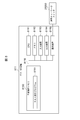
- 1 is an overall configuration diagram of a test execution system in the present embodiment.
- 1 is an overall configuration diagram of a computer system. It is an internal block diagram of a server apparatus. It is an internal block diagram of a virtual machine. It is an internal block diagram of a storage apparatus. It is an internal block diagram of an operation side switch. It is an internal block diagram of a management computer. It is an internal block diagram of a test computer. It is a logic block diagram of management program information. It is a logical block diagram of VM structure definition information. It is a logical block diagram of external address allocation information. It is a conceptual diagram of the physical HBA information contained in server configuration information. It is a conceptual diagram of the logical HBA information contained in server configuration information.
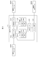
- FIG. 1 shows the overall configuration of a test execution system 1 in the first embodiment.
- the test execution system includes a plurality of test computers 811 and 812, an operation network switch 20000 for connection to the operation side network, a plurality of integrated systems 111 and 112, a management network switch 10000 for connection to the management side network, The replication SAN switch 30000 and the management computer 711 are included.
- the plurality of test computers 811 and 812 and the plurality of integrated systems 111 and 112 are connected to each other via the operation network switch 20000 so as to communicate with each other.
- the plurality of integrated systems 111 and 112 and the management computer 711 are connected to each other via a management network switch 10000 so that they can communicate with each other.
- the integrated system 111 and the integrated system 112 are connected to each other via a replication SAN switch 30000 so that they can communicate with each other.
- the test computer 811 connects to the integrated system 111 or 112 via the operation network switch 20000 and performs various verifications.
- the test computer 811 is a computer owned by the web application development base, and executes a test tool on the integrated system 112 to verify the operation of the web application.
- the internal configuration of the test computer 811 will be described later (FIG. 8).
- the test computer 812 is connected to the integrated system 111 or 112 and performs various verifications, like the test computer 811.
- the test computer 812 is a computer owned by the database application development base, and executes a test tool on the integrated system 112 to verify the operation of the database application.
- the integrated system 111 is a single computer system in which server devices, storage devices, and network devices are integrated.
- the integrated system 112 is a system created by duplicating the integrated system 111, and is similarly a single computer system in which server devices, storage devices, and network devices are integrated.
- various configurations of the integrated system 111 are copied to the integrated system 112, so that a test environment that has been previously built in the integrated system 111 is to be built in the integrated system 112. is there. Therefore, the integrated system 111 may be described as a replication source and the integrated system 112 may be described as a replication destination. The internal configuration of these integrated systems 111 and 112 will be described later (FIGS. 2 to 6).
- the management computer 711 acquires and manages various pieces of configuration information of the server device, the storage device, and the network device that configure each of the integrated systems 111 and 112 via the management network switch 10000. Based on the various pieces of configuration information to be managed, for example, the test environment of the integrated system 111 is copied to the integrated system 112.
- the internal configuration of the management computer 711, various configuration information managed by the management computer 711, and test environment replication processing executed with reference to the various configuration information will be described later (FIGS. 7, 9 to 22).
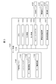
- FIG. 2 shows the internal configuration of the integrated system 111.
- the integrated system 111 includes a management side switch 5101, an operation side switch 6101, a plurality of server apparatuses 1101 and 1102, a SAN switch 4101, and a storage apparatus 3101.
- the management-side switch 5101 is a switch for connecting the management network switch 10000 to the plurality of server apparatuses 1101 and 1102 and the storage apparatus 3101 so that they can communicate with each other.
- the management computer 711 can acquire various types of configuration information of the integrated system 111 via the management side switch 5101.
- the operation-side switch 6101 is a switch for connecting the operation network switch 20000, the management-side switch 5101, and the plurality of server apparatuses 1101 and 1102 so that they can communicate with each other. Via the operation side switch 6101, the test computer 811 or 812 can verify the operation of various applications by executing a test tool on the integrated system 111.
- the server apparatus 1101 is configured by arranging a plurality of virtual machines (VM: Virtual Machine) 2101 and 2102.
- the server apparatus 1102 is configured by arranging a plurality of VMs 2103 and 2104.
- the server apparatuses 1101 and 1102 acquire virtual machine image files corresponding to the virtual machines 2102 to 2104 from the storage apparatus 3010 via the SAN switch 4101 and execute the respective virtual machines 2102 to 2104.
- the internal configuration of these virtual machines will be described later (FIG. 4).
- the SAN switch 4101 is a switch for connecting the server apparatuses 1101 and 1102 and the storage apparatus 3101 so that they can communicate with each other via a SAN (Storage Area Network).
- SAN Storage Area Network
- the storage apparatus 3101 includes a plurality of physical disks (not shown), and is configured by arranging a plurality of logical volumes in storage areas provided by the plurality of physical disks. For example, virtual machine image files corresponding to the virtual machines 2101 to 2104 are stored in each of the plurality of logical volumes.
- the duplication SAN switch 30000 is a switch for connecting the duplication source storage apparatus 3101 and the duplication destination integrated system 112 so that they can communicate with each other.
- the management computer 711 can replicate the data stored in the storage apparatus 3101 to the storage apparatus of the integrated system 112 that is the replication destination via the SAN switch 30000 for replication.
- the internal configuration of the duplication destination integrated system 112 is the same as that of the duplication source integrated system 111 described above, and a description thereof will be omitted here.
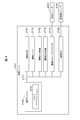
- FIG. 3 shows an internal configuration diagram of the server device 1101 that is the replication source.
- the server device 1101 is a central processing unit (CPU) 1111 that comprehensively controls the operation of the server device 1101, a memory 1112, an input device 1113, an output device 1114, a host bus adapter 1115, a management communication device 1116, and an operation communication A device 1117 and a nonvolatile memory 1150 are included. These physical resources are connected via a system bus 1118 so that they can communicate with each other.
- CPU central processing unit
- the CPU 1111 loads various programs stored in the nonvolatile memory 1150 into the memory 1112 and executes instructions described in the various programs.
- execution of an instruction described in a program by the CPU may be described as “execute the program”.
- the memory 1112 loads various programs stored in the nonvolatile memory 1150 and stores data generated when the programs are executed.
- the input device 1113 is a device for receiving input from a user, and is, for example, a keyboard or a mouse.
- the output device 1114 is a device for displaying output to the user, and is, for example, a display device.
- the host bus adapter 1115 is connected to the SAN switch 4101 and performs input / output processing between the server device 1101 and the storage device 3101.
- the management-side communication device 1116 is connected to the management-side switch 5101, receives a management operation execution request from the management computer 711, and performs transmission / reception processing for transmitting the management operation execution result to the management computer 711.
- the operation side communication device 1117 is connected to the operation side switch 6101, receives a test execution request from the test computer 811 or 812, and performs transmission / reception processing for transmitting the test execution result to the test computer 811 or 812.
- the non-volatile memory 1150 stores an OS, various programs, and various data necessary for the operation of the server device 1101, and stores a hypervisor 1151, a server configuration management program 1152, and server configuration information 1153.
- the hypervisor 1151 is a program for operating the virtual machines 2101 and 2102 on the server device 1101. Physical resources such as the CPU 1111, the memory 1112, the host bus adapter 1115, and the operation side communication device 1117 are transferred to the virtual machines 2101 and 2102. The resources are virtualized so that these physical resources can be shared between the virtual machines 2101 and 2102, and resource management of the virtual machines 2101 and 2102 is performed.
- the server configuration management program 1152 acquires the configuration information of the server device 1101, distributes physical resources to the virtual machines 2101 and 2102 operating on the server device 1101, and addresses the logical host bus adapter 2115 and logical NIC 2116 (FIG. 4). Is a program for starting or stopping the virtual machines 2101 and 2102. Note that the management computer 711 can execute the server configuration management program 1152 via the management communication device 1116.
- the server configuration information 1153 includes information indicating the relationship between the virtual machines 2101 and 2102 operating on the server device 1101 and the virtual machine image, information indicating the amount of physical resources distributed to the virtual machines 2101 and 2102, and a logical host bus
- the configuration information of the server apparatus 1101 including the address of the adapter 2115 or the logical NIC 2116 (FIG. 4) is stored.
- Information in which the test environment identification information is added to the server configuration information 1153 is stored in the management computer 711 as server configuration information 7156.
- the internal configuration of the server apparatus 1102 is the same as that of the server apparatus 1101 described above, and a description thereof is omitted here.
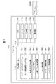
- FIG. 4 shows the internal configuration of the virtual machine 2101.
- the virtual machine 2101 includes a logical CPU 2111 that comprehensively controls the operation of the virtual machine 2101, a logical memory 2112, a logical input device 2113, a logical output device 2114, a logical host bus adapter 2115, a logical NIC (Network Interface Card) 2116, and a logical A disk 2150. These logical resources are connected via a system bus 2117 so that they can communicate with each other.
- the logical CPU 2111 is a logical CPU assigned to the virtual machine 2101 from the hypervisor 1151.
- the logical CPU 2111 loads various programs stored in the logical disk 2150 into the logical memory 2112 and executes instructions described in the various programs.
- execution of instructions described in a program by a logical CPU may be described as “execute the program”.
- the logical memory 2112 is a logical memory allocated to the virtual machine 2101 from the hypervisor 1151.
- the logical memory 2112 loads a program stored in the logical disk 2150 and stores data generated when the program is executed.
- the logical input device 2113 is a logical input device assigned to the virtual machine 2101 from the hypervisor 1151.
- the logical input device 2113 is a device for receiving input from the user, and is, for example, a keyboard or a mouse.
- the logical output device 2114 is a logical output device assigned to the virtual machine 2101 from the hypervisor 1151.
- the logic output device 2114 is a device for displaying the output to the user, and is, for example, a disc player.
- the logical host bus adapter 2115 is a logical host bus adapter allocated from the hypervisor 1151 to the virtual machine 2101.
- the logical host bus adapter 2115 is connected to the SAN switch 4101 via the host bus adapter 1115, and performs input / output processing between the virtual machine 2101 and the storage apparatus 3101.
- the logical communication device 2116 is a logical communication device assigned from the hypervisor 1151 to the virtual machine 2101.
- the logical communication device 2116 is connected to the operation side switch 6101 via the operation side communication device 1117, receives a test execution request from the test computer 811 or 811, and transmits and receives a test execution result to the test computer 811 or 812. Process.
- the logical disk 2150 stores an OS necessary for the operation of the virtual machine 2101, various programs, and various data, and also stores a test application 2151.
- the test application 2151 is a test target application, executes processing in response to a test execution request from the test computer 811 or 812, and transmits a test execution result to the test computer 811 or 812.
- FIG. 5 shows the internal configuration of the storage apparatus 3101.
- the storage apparatus 3101 includes a CPU 3111 that centrally controls the operation of the storage apparatus 3101, a memory 3112, a control apparatus 3113, a physical disk 3114, a physical port 3117, a duplication physical port 3119, a communication apparatus 3120, and a nonvolatile memory 3150. Composed. These physical resources are connected to each other via a system bus 3121 so that they can communicate with each other.
- logical resources such as a logical volume 3115, a logical port 3116, and a duplication logical port 3118 provided by these physical resources are set.
- the CPU 3111 loads various programs stored in the nonvolatile memory 3150 to the memory 3112 and executes instructions described in the various programs.
- the memory 3112 loads various programs stored in the nonvolatile memory 3150 and stores data generated when the various programs are executed.
- the control device 3113 manages physical resources including the CPU 3111, the memory 3112, and the communication device 3120, and controls the physical port 3117 and the physical disk 3114.
- the physical disk 3114 stores application programs and data. There are usually a plurality of physical disks 3114, and the plurality of physical disks 3114 are configured as virtual disks with redundancy.
- An example of a configuration that provides redundancy is RAID (Redundant Arrays of Inexpensive Disks), but is not limited to RAID.
- the logical volume 3115 provides a storage area for storing data of the server apparatuses 1101 and 1102 and image files of the virtual machines 2101 to 2104.
- the entity of the storage area provided by the logical volume 3115 is allocated from the physical disk 3114.
- the logical port 3116 is a logical port assigned from the physical port 3117, is connected to the SAN switch 4101, and performs input / output processing between the virtual machines 2101 to 2104 and the storage apparatus 3101.
- the physical port 3117 is connected to the SAN switch 4101 and performs input / output processing between the server apparatus 1101 or 1102 and the storage apparatus 3101.
- the duplication logical port 3118 is a logical port assigned from the duplication physical port 3119, is connected to the duplication SAN switch 30000, and is arranged in the duplication source logical volume and the duplication destination integrated system 112. Performs input / output processing with the volume.
- the replication physical port 3119 is connected to the replication SAN switch 30000 and is used to create a replication in the storage apparatus in the replication destination integrated system 112.
- the communication device 3120 is connected to the management-side switch 5101, receives a management operation execution request from the management computer 711, and performs transmission / reception processing for transmitting the management operation execution request to the management computer 711.
- the nonvolatile memory 3150 stores a storage configuration management program 3151 and storage configuration information 3152 in addition to an OS, various programs and various data necessary for the operation of the storage apparatus 3101.
- the storage configuration management program 3151 acquires the configuration information of the storage device 3101, creates or deletes a logical volume on the storage device 3101, creates, deletes, puts online or offline the logical port 3116 or the replication logical port 3118, This is a program for assigning a logical port 3116 to a logical volume, setting identification information for the logical volume, and copying data stored in the logical volume. Note that the management computer 711 can execute the storage configuration management program 3151 via the communication device 3120.
- the storage configuration information 3152 stores configuration information including a plurality of physical resources on the storage apparatus 3101 and logical resources such as logical volumes, logical ports, and duplication logic configured from these physical resources. Information obtained by adding the test environment identification information to the storage configuration information 3152 is stored in the management computer 711 as the storage configuration information 7157.
- FIG. 6 shows the internal configuration of the operation side switch 6101.
- the operation side switch 6101 includes a CPU 6111 that comprehensively controls the operation of the operation side switch 6101, a memory 6112, a control device 6113, an external port 6114, internal ports 61151 and 61152, a communication device 6116, and a nonvolatile memory 6150.
- the These physical resources are connected via a system bus 6117 so that they can communicate with each other.
- the CPU 6111 loads various programs stored in the nonvolatile memory 6150 into the memory 6112 and executes instructions described in the various programs.
- the memory 6112 loads various programs stored in the nonvolatile memory 6150, and stores various data generated when the programs are executed.
- the control device 6113 manages physical resources including the CPU 6111, the memory 6112, and the communication device 6116, and controls the external port 6114 and the internal ports 61151 and 61152.
- the external port 6114 is connected to the operation network switch 20000, and performs communication processing between the integrated system 111 and the test computer 811 or 812.
- the internal port 61151 is connected to the server device 1101 and performs communication processing between the operation side switch 6101 and the server device 1101.
- the internal port 61152 is connected to the server apparatus 1102 and performs communication processing between the operation side switch 6101 and the server apparatus 1102.
- the communication device 6116 is connected to the management-side switch 5101, receives a management operation execution request from the management computer 711, and performs transmission / reception processing for transmitting the management operation execution result to the management computer 711.
- the nonvolatile memory 6150 stores an OS, various programs, and various data necessary for the operation of the operation side switch 6101, and stores a network configuration management program 6151 and network configuration information 6152.
- the network configuration management program 6151 acquires configuration information of the operation side switch 6101, controls communication between the external switch and the internal switch in the operation side switch 6101, sets an external address for the internal network, This is a program for controlling communication permission or prohibition according to a port number and communication direction (from an external network to an internal network or from an internal network to an external network). Note that the management computer 711 can execute the network configuration management program 6151 via the communication device 3120.
- the network configuration information 6152 stores configuration information including external address setting information for the internal network and communication permission or prohibition setting information according to the protocol, port number, and communication direction. Information obtained by adding the test environment identification information to the network configuration information 6152 is stored as network configuration information 7158 in the management computer 711.
- the network configuration management program 6151 and the network configuration information 6152 are described as being stored in the operation side switch 6101.
- the computers that operate the firewall are the operation side switch 6101 and the operation network switch 20000. You may arrange
- the internal configuration of the management-side switch 5101 is the same as the internal configuration of the operation-side switch 6101 described above, and a description thereof is omitted here.
- FIG. 7 shows the internal configuration of the management computer 711.
- the management computer 711 includes a CPU 7111 that comprehensively controls the operation of the management computer 711, a memory 7112, an input device 7113, an output device 7114, a communication device 7115, and a nonvolatile memory 7150. These physical resources are connected to each other via a system bus 7116 so that they can communicate with each other.
- the CPU 7111 loads various programs stored in the non-volatile memory 7150 to the memory 7112 and executes instructions described in the various programs.
- the memory 7112 loads various programs stored in the non-volatile memory 7150, and stores data generated when the various programs are executed.
- the input device 7113 is a device for receiving input from the user, and is, for example, a keyboard or a mouse.
- the output device 7114 is a device for displaying output to the user, and is, for example, a disc player.
- the communication device 7115 is connected to the management network switch 10000, transmits a management operation execution request to the server devices 1101, 1102, the storage device 3101, and various switches, and also displays the management operation execution result from these devices and switches. Performs transmission / reception processing.
- the non-volatile memory 7150 stores an OS, various programs, and various data necessary for the operation of the management computer 711, as well as a system configuration acquisition program 7151, a test environment replication program 7152, management program information 7153, and VM configuration definition information 7154. , External address allocation information 7155, server configuration information 7156, storage configuration information 7157, and network configuration information 7158 are stored.
- the system configuration acquisition program 7151 transmits a configuration information acquisition request to the server configuration management program 1152, the storage configuration management program 3151 and the network configuration management program 6151, and receives the configuration information as an execution result.
- the server configuration information 7156, the storage configuration information 7157, and the network configuration information 7158 are stored in the nonvolatile memory 7150.
- the system configuration acquisition program 7151 may be executed in response to an administrator's request, or may be periodically executed by a scheduler such as an OS.
- the test environment duplication program 7152 is a program for duplicating the test environment built in one integrated system 111 to the duplication destination integrated system 112.
- the test environment replication program 7152 sends a configuration change execution request to the server device (server configuration management program), storage device (storage configuration management program), and operation side switch (network configuration management program) in the integrated system 112 at the replication destination. To create a duplicate of the test environment. Details of the test environment replication process will be described later (FIG. 22).
- management program information 7153 execution of configuration changes to the server device 1101 (server configuration management program 1152), storage device 3101 (storage configuration management program 3151), and operation side switch 6101 (network configuration management program 6151) in the integrated system 111 is executed. Contains address information when sending the request. Details will be described later (FIG. 9).
- the VM configuration definition information 7154 includes virtual machines 2101 to 2104 operating in the integrated system 111, logical host bus adapters 2115 assigned to these virtual machines 2101 to 2104, and logical host bus adapters 2115. Configuration information including the logical port 3116 being configured. Details will be described later (FIG. 10).
- the external address assignment information 7155 includes information including an external address used when a setting operation is performed on the operation side switch 6101 using the network configuration management program 6151. Details will be described later (FIG. 11).
- the server configuration information 7156 includes information obtained by adding the test environment identification information to the server configuration information 1153 acquired from the server configuration management program 1152.
- the storage configuration information 7157 includes information obtained by adding test environment identification information to the storage configuration information 3152 acquired from the storage configuration management program 3151.
- the network configuration information 7158 includes information obtained by adding test environment identification information to the network configuration information 6152 acquired from the network configuration management program 6151. Details of these will be described later (FIGS. 12 to 21).
- FIG. 8 shows the internal configuration of the test computer 811.
- the test computer 811 includes a CPU 8111 that comprehensively controls the operation of the test computer 811, a memory 8112, an input device 8113, an output device 8114, a communication device 8115, and a nonvolatile memory 8150. These physical resources are connected via a system bus 8116 so that they can communicate with each other.
- the CPU 8111 loads various programs stored in the non-volatile memory 8150 to the memory 8112 and executes instructions described in the various programs.
- the memory 8112 loads various programs stored in the nonvolatile memory 8150 and stores data generated when the various programs are executed.
- the input device 8113 is a device for receiving input from the user, and is, for example, a keyboard or a mouse.
- the output device 8114 is a device for displaying output to the user, and is, for example, a disc player.
- the communication device 8115 is connected to the operation network switch 20000, receives a test execution request from the test computer 811, and performs transmission / reception processing for transmitting a test execution result to the test computer 811.
- the nonvolatile memory 8150 stores an OS, various programs, and various data necessary for the operation of the test computer 811, and also stores a test execution program 8151.
- the test execution program 8151 is a program for causing the test application 2151 to execute a test, transmits a test execution request to the test application 2125, and receives a test result from the test application 2125.
- test computer 812 is the same as that of the test computer 811 described above, and a description thereof will be omitted here.
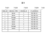
- FIG. 9 shows the logical configuration of the management program information 7153.
- the management program 7153 is information created when an administrator registers a device in the management computer 711, and stores the addresses of the server device, the storage device, and the operation side switch. This management program information 7153 is used in the test environment construction process (FIG. 22). Note that various information and various tables described later are similarly used in the test environment construction process.
- the management program information 7153 includes a test environment identification information column 71531, a device type column 71532, a device ID column 71533, and an address column 71534.
- the test environment identification information column 71531 stores test environment identification information for specifying a unique integrated system in the test execution system 1.
- the device type column 71532 information indicating the type of each device constituting the integrated system is stored.
- the device ID column 71533 identification information of each device constituting the integrated system is stored.
- the address column 71534 stores an address for the management computer 711 to send an execution request to the management program (for example, the server configuration management program 1152) in each apparatus constituting the integrated system.
- an integrated system with test environment identification information “1” includes two server devices with the device type “Server” and one storage device with the device type “Storage”. It is shown that the device type is composed of one operation side switch whose switch type is “Switch”. In addition, it is indicated that the address of the server device whose device type is “Server” and whose device ID is “1” is “192.168.10.1”.
- the test environment identification information of the integrated system 111 is “1” and the test environment identification information of the integrated system 112 is “2”.
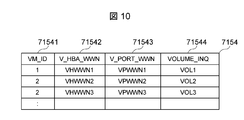
- FIG. 10 shows the logical configuration of the VM configuration definition information 7154.
- the VM configuration definition information 7154 is information that is created when an administrator registers a virtual machine in the management computer 711, and stores information on the connection relationship between the virtual machine and the logical volume.
- the VM configuration definition information 7154 includes a virtual machine ID column 71541, a logical host bus adapter WWN column 71542, a logical port WWN column 71543, and a logical volume identifier column 71544.
- the logical host bus adapter WWN column 71542 stores the world wide name (WWN: World Wide Name) of the logical host bus adapter assigned to the virtual machine as information for specifying a globally unique logical host bus adapter.
- the logical port WWN column 71543 stores the logical port WWN as information for specifying a globally unique logical port.
- information for identifying a unique logical volume in the integrated system is stored, and for example, identification information of a logical volume stored in the page 83h of response data of the SCSI INQUIRY command is stored.
- a logical host bus adapter whose logical host bus adapter WWN is “VHWWN1” is assigned to a virtual machine whose virtual machine ID is “1”, and this logical host bus adapter is connected to the logical port WWN. Is connected to a logical volume whose logical port is “VPWWN1” and whose logical volume identifier is “VOL1”.
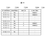
- FIG. 11 shows a logical configuration of the external address assignment information 7155.
- the external address assignment information 7155 is information that is created when the administrator assigns a reserved address to the logical NIC in the management computer 711, and whether the reserved address and whether this address has been assigned or not. Information is stored.
- the external address assignment information 7155 includes a logical NIC address field 71551, an assigned field 71552, a test environment identification information field 71553, and a logical NIC MAC address field 71554.
- the logical NIC address field 71551 stores an IP address reserved in the test execution system 1 for assignment to the logical NIC of the virtual machine.
- the assigned column 71552 stores information indicating whether or not the assignment has been made.
- the test environment identification information column 71553 stores test environment identification information for specifying a unique integrated system in the test execution system 1.
- the logical NIC MAC address column 71554 stores the MAC address of the logical NIC.
- the logical NIC whose address is “10.101.11.1” has already been assigned to the virtual machine (“Yes”), and this logical NIC is arranged in the integrated system 111.
- the MAC address is “VNMAC1”.
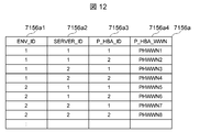
- FIG. 12 shows a logical configuration of the physical HBA information 7156a included in the server configuration information 7156.
- the physical HBA information 7156a is information created by the administrator registering in the management computer 711, and stores information on the physical host bus adapter.
- the physical HBA information 7156a includes a test environment identification information column 7156a1, a server device ID column 7156a2, a physical host bus adapter ID column 7156a3, and a physical host bus adapter WWN column 7156a4.
- test environment identification information column 7156a1 test environment identification information for specifying a unique integrated system in the test execution system 1 is stored.
- the server apparatus ID column 7156a2 stores identification information for specifying a unique server apparatus in the integrated system.
- the physical host bus adapter ID column 7156a3 stores identification information for specifying a unique physical host bus adapter in the server device.
- the physical host bus adapter WWN column 7156a4 stores a WWN that identifies a globally unique physical host bus adapter.
- the server device with the server device ID “1” has two physical host bus adapters with the physical host bus adapter IDs “1” and “2”, and the physical host adapter ID “1” It is indicated that the WWN of the host bus adapter is “PHWWN1”.
- FIG. 13 shows the logical configuration of the logical HBA information 7156b included in the server configuration information 7156.
- the logical HBA information 7156b is information created by the administrator registering in the management computer 711, and stores logical host bus adapter information.
- the logical HBA information 7156b includes a test environment identification information column 7156b1, a server device ID column 7156b2, a physical host bus adapter ID column 7156b3, a logical host bus adapter ID column 7156b4, and a logical host bus adapter WWN column 7156b5.
- test environment identification information column 7156b1 test environment identification information for specifying a unique integrated system in the test execution system 1 is stored.
- the server apparatus ID column 7156b2 stores identification information for specifying a unique server apparatus in the integrated system.
- the physical host bus adapter ID column 7156b3 stores identification information for specifying a unique physical host bus adapter in the server device.
- the logical host bus adapter ID column 7156b4 stores identification information of the physical host bus adapter.
- the logical host bus adapter WWN column 7156b5 stores the WWN of the logical host bus adapter.
- the integrated system with the test environment identification information “1” there are two server devices with the server device IDs “1” and “2”, for a total of four server devices. It is shown that.
- the server device with the server device ID “1” has two physical host adapters with the physical host adapter IDs “1” and “2”, and the physical host adapter with the physical host adapter ID “1”. Indicates that a logical host adapter having a logical host adapter ID “1” is assigned. Further, it is indicated that the WWN of this logical host adapter is “VHWWN1”.
- FIG. 14 shows the logical configuration of the physical NIC information 7156c included in the server configuration information 7156.
- the physical NIC information 7156c is information created by the administrator registering in the management computer 711, and stores information on the physical NIC.
- the physical NIC information 7156c includes a test environment identification information column 7156c1, a server device ID column 7156c2, a physical NIC ID column 7156c3, and a physical NIC MAC address column 7156c4.
- test environment identification information column 7156c1 test environment identification information for specifying a unique integrated system in the test execution system 1 is stored.
- the server apparatus ID column 7156c2 stores identification information for specifying a unique server apparatus in the integrated system.
- Physical NIC identification information is stored in the physical NIC ID column 7156c3.
- the physical NIC MAC address column 7156c4 stores the MAC address of the physical NIC.
- the server device with the server device ID “1” has two physical NICs with physical NIC IDs “1” and “2”, and the MAC of the physical NIC with the physical NIC ID “1”. It is shown that the address is “PNMAC1”.
- FIG. 15 shows the logical configuration of the logical NIC information 7156d included in the server configuration information 7156.
- the logical NIC information 7156d is information created by the administrator registering in the management computer 711, and stores logical NIC information.
- the logical NIC information 7156d includes a test environment identification information column 7156d1, a server device ID column 7156d2, a physical NIC ID column 7156d3, a logical NIC ID column 7156d4, a logical NIC MAC address column 7156d5, and an internal address column 7156d6. Is done.
- test environment identification information column 7156d1 test environment identification information for specifying a unique integrated system in the test execution system 1 is stored.
- the server apparatus ID column 7156d2 stores identification information for specifying a unique server apparatus in the integrated system.
- the physical NIC ID field 7156d3 stores identification information of the physical NIC.
- the logical NIC ID column 7156d4 stores identification information of the logical NIC.
- the logical NIC MAC address column 7156d5 stores the MAC address of the logical NIC created from the physical NIC.
- the internal address column 7156d6 stores an address assigned to the logical NIC for use in communication within the integrated system.
- the integrated system with the test environment identification information “1” there are two server devices with the server device IDs “1” and “2”, for a total of four server devices. It is shown that.
- the server device with the server device ID “1” has two physical NICs with the physical NIC ID “1” and “2”, and is created from the physical NIC with the physical NIC ID “1”. It is indicated that the ID of the logical NIC is “1” and the MAC address of this logical NIC is “VNMAC1”. Further, it is indicated that the internal address of this logical NIC is “192.168.11.1”.
- FIG. 16 shows a logical configuration of the physical port information 7157a included in the storage configuration information 7157.
- the physical port information 7157a is information created by an administrator registering in the management computer 711, and stores physical port information.
- the physical port information 7157a includes a test environment identification information column 7157a1, a storage device ID column 7157a2, a physical port ID column 7157a3, a physical port WWN column 7157a4, and a system copy column 7157a5.
- the test environment identification information column 7157a1 stores test environment identification information that identifies a unique integrated system in the test execution system 1.
- the storage device ID column 7157a2 stores identification information for specifying a unique storage device in the integrated system.
- the physical port ID column 7157a3 stores identification information for specifying a unique physical port in the storage apparatus.
- the physical port WWN column 7157a4 stores the WWN of the physical port.
- the system copy column 7157a5 stores information indicating whether the physical port is a physical port for test environment replication connected to the replication SAN switch 30000.
- one storage device with the storage device ID “1” is arranged, and the physical port ID is “1”. It is shown that a total of three physical ports “1” to “3” are arranged.
- the WWN of the physical port with the physical port ID “1” is “PPWWN1”, which indicates that this physical port is not used for test environment duplication (“No”). It is also shown that a physical port whose physical port WWN is “PPWWN3” is used for test environment duplication (“Yes”).
- the initial value of the system copy field 7157a5 is No for all physical ports, and is set to Yes after being connected.
- FIG. 17 shows the logical configuration of the logical port information 7157b included in the storage configuration information 7157.
- the logical port information 7157b is information created by the administrator registering in the management computer 711, and stores logical port information.
- the logical port information 7157b includes a test environment identification information column 7157b1, a storage device ID column 7157b2, a physical port ID column 7157b3, a logical port ID column 7157b4, and a logical port WWN column 7157b5.
- test environment identification information column 7157b1 test environment identification information for specifying a unique integrated system in the test execution system 1 is stored.
- the storage device ID column 7157b2 stores identification information for specifying a unique storage device in the integrated system.
- the physical port ID column 7157b3 stores identification information for specifying a unique physical port in the storage apparatus.
- the logical port ID column 7157b4 stores identification information for specifying a unique logical port among physical ports.
- the logical port WWN column 7157b5 stores the WWN of the logical port.
- one storage device with the storage device ID “1” is arranged, and the physical port ID is “1”. It is shown that a total of three physical ports “1” to “3” are arranged. Also, a logical port with a logical port ID “1” is created from a physical port with a physical port ID “1”, and the WWN of this logical port is “VPWWN1”.
- FIG. 18 shows the logical configuration of the logical volume information 7157c included in the storage configuration information 7157.
- the logical volume information 7157c is information created by the administrator registering in the management computer 711, and stores logical volume information.
- the logical volume information 7157c includes a test environment identification information column 7157c1, a storage device ID column 7157c2, a logical volume ID column 7157c3, a logical volume identifier column 7157c4, and a volume size column 7157c5.
- the test environment identification information column 7157c1 stores test environment identification information for specifying a unique integrated system in the test execution system 1.
- the storage device ID column 7157c2 stores identification information for specifying a unique storage device in the integrated system.
- the logical volume ID column 7157c3 stores identification information for specifying a unique logical volume in the storage apparatus.
- information for specifying a unique logical volume in the integrated system is stored. For example, identification information of a logical volume stored in the page 83h of the response data of the SCSI INQUIRY command is stored.
- the volume size column 7157c5 stores the size of the logical volume.
- one storage device with the storage device ID “1” is arranged, and this storage device has the logical volume ID “1”. It is shown that a total of three logical volumes “1” to “3” are set. Further, the identification information of the logical volume with the logical volume ID “1” is “VOL1”, and the volume size of this logical volume is “100 GB”.
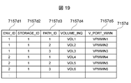
- FIG. 19 shows a logical configuration of path information 7157d included in the storage configuration information 7157.
- the path information 7157d is information created by registration by the administrator in the management computer 711, and stores information on paths connecting logical ports and logical volumes.
- the path information 7157d includes a test environment identification information column 7157d1, a storage device ID column 7157d2, a path ID column 7157d3, a logical volume identifier column 7157d4, and a logical port WWN column 7157d5.
- the test environment identification information column 7157d1 stores test environment identification information that identifies a unique integrated system in the test execution system 1.
- the storage device ID column 7157d2 stores identification information for specifying a unique storage device in the integrated system.
- the path ID column 7157d3 stores identification information for specifying a unique path in the storage device.
- the logical volume identifier column 7157d4 information for identifying a unique logical volume in the integrated system is stored, and for example, identification information of the logical volume stored in the page 83h of response data of the SCSI INQUIRY command is stored.
- the logical port WWN column 7157d5 stores the WWN of the logical port.
- the path ID is “1”. It is shown that a total of three paths “” to “3” are set.
- the path with the path ID “1” is a path for connecting the logical volume with the identification information “VOL1” and the logical port with the WWN “VPWWN1”.
- FIG. 20 shows a logical configuration of the address mapping information 7158a included in the network configuration information 7158.
- the address mapping information 7158a is information created by registration by the administrator in the management computer 711, and an address for accessing the virtual machine (logical NIC) from the outside of the integrated system, and the inside of the integrated system. Information that associates an address for accessing a virtual machine (logical NIC) is stored.
- the address mapping information 7158a includes a test environment identification information column 7158a1, a logical NIC MAC address column 7158a2, an internal address column 7158a3, and an external address column 7158a4.
- test environment identification information column 7158a1 test environment identification information for specifying a unique integrated system in the test execution system 1 is stored.
- the logical NIC MAC address column 7158a2 stores the MAC address of the logical NIC.
- the internal address column 7158a3 stores an address assigned to the logical NIC in order to access the logical NIC of the virtual machine inside the integrated system.
- the external address column 7158a4 stores an address assigned to the logical NIC in order to access the logical NIC of the virtual machine from the outside of the integrated system.
- FIG. 21 shows a logical configuration of the communication control information 7158b included in the network configuration information 7158.
- the communication control information 7158b is information created by an administrator registering in the management computer 711, and stores information related to communication control between the integrated system and the outside.
- the communication control information 7158b includes a test environment identification information column 7158b1, a communication direction column 7158b2, a protocol column 7158b3, a port number column 7158b4, a target address column 7158b5, and an access column 7158b6.
- test environment identification information column 7158b1 test environment identification information for specifying a unique integrated system in the test execution system 1 is stored.
- the communication direction column 7158b2 stores information indicating the direction of communication.
- the protocol column 7158b3 stores a protocol used for communication.
- a port number is stored in the port number column 7158b4.
- the target address column 7158b5 stores an access destination address. Information indicating permission or prohibition of access is stored in the access column 7158b6.
- an integrated system with test environment identification information “1” is bidirectional “ANY” in which the communication direction may be either from the integrated system to the outside or from the outside to the integrated system.
- ANY which can be any
- ANY which can be any port number
- ANY which can be any target address
- the communication direction is from the outside to the integrated system (“OUT_IN”), the protocol is “http”, the port number is “80”, and the target address is “10.101.11.1”. It is indicated that “(ALLOW)” is permitted for communication.
- IN_OUT is stored in the communication direction column 7158b2.
- FIG. 22 shows a processing procedure for test environment construction processing in the present embodiment. This test environment construction process is executed based on the test environment replication program 7152 and the CPU 7111 when the management computer 711 receives a request from the administrator.
- the management computer 711 copies the test environment built in the integrated system 111 to the integrated system 112 and receives a request for building the test environment in the integrated system 112 from the administrator.
- the processing subject will be described as a test environment replication program 7152.
- the test environment replication program 7152 refers to the management program information 7153, and sends a virtual machine to a server device (for example, the server devices 1101 and 1102) whose test environment identification information is “1” and whose device type is “Server”. A stop request is transmitted (S101).
- the server configuration management program 1152 that has received the request in step S101 stops the replication source virtual machines (for example, virtual machines 2101 to 2104).
- the test environment replication program 7152 refers to the logical volume information 7157c, and the test environment identification information is “1”, the storage device ID is “1”, the logical volume IDs are “1” to “3”, and the volume Logical volumes having sizes of “100 GB”, “100 GB”, and “500 GB” are respectively created in a storage device (for example, a storage device of the integrated system 112) whose test environment identification information is “2” (S102).
- the test environment duplicating program 7152 refers to the management program information 7153, and the storage device whose test environment identification information is “2”, the device type is “Storage”, and the device ID is “1” (storage device ID). Is designated as a replication destination storage apparatus, and a logical volume creation request is transmitted to the storage apparatus by designating the same logical volume ID, the same volume size, and a different logical volume identifier as the replication source.
- the copy destination storage configuration management program 3151 that has received the request in step S102 creates a logical volume in the copy destination.
- test environment duplicating program 7152 refers to the physical port information 7157a and the logical volume information 7157c, and the test environment identification information indicates a physical port whose test environment identification information is “1” and whose system copy is “Yes”. An allocation request to be allocated to the logical volume “1” is transmitted.
- the test environment duplication program 7152 refers to the physical port information 7157a and the logical volume information 7157c, and the test identification information indicates the physical port whose test environment identification information is “2” and whose system copy is “Yes”. An allocation request to be allocated to the logical volume “2” is transmitted (S103).
- the copy source and copy destination storage configuration management program 3151 that received the request in step S103 allocates the designated physical port to the designated volume at the copy source and the copy destination.
- test environment replication program 7152 transmits an online request for the physical port assigned in step S103 to the replication source and replication destination storage apparatuses (S104).
- the replication source and replication destination storage configuration management program 3151 that has received the request in step S104 brings the designated physical port online.
- test environment replication program 7152 transmits a data replication request for replicating the data stored in each replication source logical volume to each replication destination logical volume created in step S102 (S105).
- the copy source and copy destination storage configuration management program 3151 that received the request in step S105 copies the data of the designated logical volume.
- test environment replication program 7152 transmits an offline request for the physical port assigned in step S103 (S106).
- the copy source and copy destination storage configuration management program 3151 that received the request in step S106 takes the specified physical port offline.
- test environment replication program 7152 transmits an allocation cancellation request for deallocating the physical port allocated in step S103 (S107).
- the copy source and copy destination storage configuration management program 3151 that received the request in step S107 cancels the assignment of the designated physical port.
- test environment duplication program 7152 refers to the logical volume information 7157c, sets the test environment identification information “2” to logical volume identifiers (“VOL4”, “VOL5”, “VOL6”) and the test environment identification information “1”.
- VOL4 logical volume identifiers
- VOL5 logical volume identifiers
- VOL6 test environment identification information
- the copy destination storage configuration management program 3151 that received the request in step S108 sets the same logical volume identifier as the logical volume of the integrated system 111 to the logical volume of the integrated system 112.
- test environment replication program 7152 refers to the physical port information 7157a and the logical port information 7157b, and the storage device ID, physical port ID, logical port ID, and logical port WWN of the logical port whose test environment identification information is “1” are determined.
- a logical port creation request is transmitted to the storage device whose test environment identification information is “2” so as to match (S109).
- the copy destination storage configuration management program 3151 that has received the request in step S109 creates a logical port ID and a logical port WWN specified for the physical port specified by the storage device ID and the physical port ID.
- test environment replication program 7152 refers to the path information 7157d so that the corresponding storage apparatus ID, path ID, logical volume identifier, and logical port WWN match for all paths with the test environment identification information “1”.
- a path creation request is transmitted to the storage device having the test environment identification information “2” (S110).
- the replication destination storage configuration management program 3151 that received the request in step S110 newly creates a path identical to the path in the storage device with the test environment identification information “1” in the storage device with the test environment identification information “2”. Assign a logical port to the logical volume.
- test environment replication program 7152 refers to the physical HBA information 7156a and the logical HBA information 7156b, and the server device ID, physical host bus adapter ID, and logical host bus adapter of the logical host bus adapter whose test environment identification information is “1”.
- a logical host bus adapter creation request is transmitted to the server device having the test environment identification information “2” so that the ID matches the logical host bus adapter WWN (S111).
- the copy destination server configuration management program 1152 that has received the request in step S111 determines a logical host bus adapter having the same configuration as the logical host bus adapter of the server device having the test environment identification information “1” and the test environment identification information “2”. To the server device.
- test environment replication program 7152 refers to the physical NIC information 7156c and the logical NIC information 7156d, and the server device ID corresponding to the logical NIC whose test environment identification information is “1”, the physical NIC ID, the logical NIC ID, A logical NIC creation request is transmitted to the server device whose test environment identification information is “2” so that the logical NIC MAC address matches the internal address (S112).
- the copy destination server configuration management program 1152 that has received the request in step S112 determines that the logical NIC having the same configuration as the logical NIC of the server device having the test environment identification information “1” is the server device having the test environment identification information “2”. To create.
- test environment replication program 7152 refers to the VM configuration definition information 7154, and transmits a virtual machine creation request to the server device having the test environment identification information “2” (S113).
- the copy destination server configuration management program 1152 that has received the request in step S113 creates a virtual machine having the same configuration as the virtual machine having the test environment identification information “1” in the server apparatus having the test environment identification information “2”. .
- test environment replication program 7152 refers to the address mapping information 7158a, and the internal address matches the logical NIC whose test environment identification information is “1”, and an unassigned address in the external address assignment information 7155 becomes an external address.
- an address mapping request is transmitted to the operation side switch whose test environment information is “2” (S114).
- the copy destination network configuration management program 6151 that has received the request in step S114 operates the address mapping whose test environment identification information is “2” for the address mapping in which only the external address is different among the address mappings whose test environment identification information is “1”. Create at the switch.
- test environment duplicating program 7152 refers to the communication control information 7158b, and the communication control information and the communication direction, protocol, port number and access permission set in the operation side switch 6101 with the test environment identification information “1” or A communication control information setting request is transmitted to the operation side switch whose test environment identification information is “2” so that the prohibition matches and the external address becomes the address assigned in step 114 (S115).
- the network configuration management program 6151 of the copy destination that has received the request in step S115 selects the communication control information whose test environment identification information is “1”, the communication control information whose test environment identification information is “2”, and which is different only in the external address. Create it on the operation side switch.
- test environment replication program 7152 refers to the management program information 7153, and transmits a virtual machine activation request to the server device whose test environment identification information is “2” and whose device type is “Server” (S116). ).
- the server configuration management program 1152 that has received the request in step S116 activates the virtual machine, and the test environment construction process ends.
- a test execution request is specified by specifying the external address assigned in step 114 from the test computer 811 or 812. And the test can be performed in the integrated system 112.
- a logical volume having the same configuration as that of the copy source integrated system is created in the copy destination integrated system. Then, bring the connection between the created logical volume and the replication source logical volume online to replicate the data stored in the replication source logical volume to the replication destination logical volume, and then replicate the connection by taking the connection offline.
- the identification information of the destination logical volume is set to match the identification information of the replication source logical volume, the logical port is set in the other replication destination storage device, and the logical host bus adapter in the replication destination server device Set the logical NIC and virtual machine, and on the operation switch at the copy destination, only the external address is different from the copy source.
- address mapping information is set so that the logical configuration of the replication source is automatically replicated to the replication destination. Therefore, according to the present embodiment, it is possible to save troublesome settings in the integrated system at the copy destination, and to quickly build a test environment in the integrated system at the copy destination. Become.
- Second Embodiment The second embodiment is different from the first embodiment in that a test environment built in advance in the integrated system is duplicated in the same integrated system.
- a test environment built in advance in the integrated system is duplicated in the same integrated system.
- FIG. 23 shows the overall configuration of the test execution system 2 in the second embodiment.
- the test execution system 2 is different from the test execution system 1 in the first embodiment in that one integrated system 121 is arranged and no duplication SAN switch is arranged.
- FIG. 24 shows the internal configuration of the integrated system 121.
- the integrated system 121 does not include the replication SAN switch in the test execution system 2, and therefore the storage system 3201 and the replication SAN switch are not connected to each other in the first embodiment. Different from the integrated system 111.
- the operation side switch 6201 has a function of logically dividing the network and setting address mapping information 7158a (FIG. 20) and communication control information 7158b (FIG. 21) for each network. Different from the operation side switch 6101 in the embodiment.
- the SAN switch 4201 has a function of logically dividing the SAN and uses the logical switch divided as the duplication SAN switch 30000 in the first embodiment, so that the SAN switch in the first embodiment is used. Different from the switch 4101.
- the storage apparatus 3201 has a function of logically dividing the storage apparatus. In the test environment, the storage apparatus 3201 is logically divided so that physical resources are equally divided in advance. Different from the storage apparatus 3101 in FIG.
- FIG. 25 shows the internal configuration of the storage device 3201.
- the storage apparatus 3201 is different from the storage apparatus 3101 in the first embodiment in that the replication physical port 3119 is connected to the SAN switch 4201 and the logical storage configuration information 3252 is stored in the nonvolatile memory 3150. Different.
- the logical storage configuration information 3153 includes a physical resource allocated to the logical storage device created in the storage device 3201, and a logical resource such as a logical volume, a logical port, and a duplication logical port composed of the physical resource. Information is stored. Information obtained by adding the test environment identification information to the logical storage configuration information 3153 is stored in the management computer 721 as the logical storage configuration information 7257.
- FIG. 26 shows the internal configuration of the management computer 721.
- the management computer 721 is different from the management computer 711 in the first embodiment in that logical storage configuration information 7257 is stored in the nonvolatile memory 7150.
- the logical storage configuration information 7257 includes information obtained by adding test environment identification information to the logical storage configuration information 3153 acquired from the storage configuration management program 3151.
- FIG. 27 shows the logical configuration of the physical port information 7257a included in the logical storage configuration information 7257.
- the physical port information 7257a is different from the physical port information 7157a (FIG. 16) in the first embodiment in that the physical port information 7257a includes a logical storage device ID column 7257a2.
- the logical storage device ID column 7257a2 stores identification information for specifying a unique logical storage device in the integrated system 121.
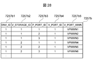
- FIG. 28 shows a logical configuration of the logical port information 7257b included in the logical storage configuration information 7257.
- the logical port information 7257b is different from the logical port information 7157b (FIG. 17) in the first embodiment in that the logical port information 7257b includes a logical storage device ID column 7257b2.
- the logical storage device ID column 7257b2 stores identification information for specifying a unique logical storage device in the integrated system 121.
- FIG. 29 shows a logical configuration of the logical volume information 7257c included in the logical storage configuration information 7257.
- the logical volume information 7257c is different from the logical volume information 7157c (FIG. 18) in the first embodiment in that it includes a logical storage device ID column 7257c2.
- the logical storage device ID column 7257c2 stores identification information for specifying a unique logical storage device in the integrated system 121.
- FIG. 30 shows the logical configuration of the path information 7257d included in the logical storage configuration information 7257.
- the path information 7257d is different from the path information 7157d (FIG. 19) in the first embodiment in that the path information 7257d includes a logical storage device ID column 7257d2.
- the logical storage device ID column 7257d2 stores identification information for specifying a unique logical storage device in the integrated system 121.
- test environment identification information in FIGS. 27 to 30 is “1”. It is shown that it is fixed to.
- test environment construction process (FIG. 22) in the first embodiment when executed, it is executed by using the logical storage device ID instead of the storage device ID.
- the test environment built in advance in the integrated system 121 can be replicated in the same integrated system 121.
- the third embodiment selects whether or not to replicate to the replication destination for each replication source logical volume, and replicates only the selected logical volume to the replication destination. Different from the first embodiment. Hereinafter, different points will be described in detail with reference to the drawings.
- FIG. 31 shows the internal configuration of the management computer 731 according to the third embodiment.
- the management computer 731 is different from the management computer 711 in the first embodiment in that an interactive test environment replication program 7352 is stored in the nonvolatile memory 7150.
- the interactive test environment replication program 7352 does not replicate the data of all the logical volumes in the integrated system 111, but the logic selected by the administrator. Duplicate volume data only.
- FIG. 32 shows the screen configuration of the volume selection screen 7311.
- the volume selection screen 7311 is a display screen displayed on the output device 7114 of the management computer 731 and is a display screen for selecting a replication target logical volume from among the replication source logical volumes.
- the volume selection screen 7311 includes a volume selection area 731A1, a storage device ID area 731A2, a logical volume ID area 731A3, a volume size area 731A4, and an execution operation area 731A5.
- volume selection area 731A1 selectable check boxes are displayed for the number of logical volumes set as the replication source.
- storage device ID area 731A2 identification information for specifying a unique storage device in the replication source integrated system is displayed.
- logical volume ID area 731A3 identification information for specifying a unique logical volume in the replication source integrated system is displayed.
- the volume size area 731A4 displays the size of the logical volume.
- the volume selection area 731A1 has a check mark in the uppermost check box, which indicates that the logical volume of the uppermost entry is selected as a replication target.
- this logical volume is set to a storage apparatus having a storage apparatus ID “1”, the logical volume ID is “1”, and the volume size is “100 GB”.
- FIG. 33 shows a processing procedure for test environment construction processing in the third embodiment.
- This test environment construction process is executed based on the interactive test environment replication program 7352 and the CPU 7111 when the management computer 711 receives an operation from the administrator.
- the processing subject will be described as an interactive test environment replication program 7352.
- the interactive test environment replication program 7352 refers to the logical volume information 7157c (FIG. 18) and acquires information on all logical volumes set in the integrated system whose test environment identification information is “1” ( S301).
- the interactive test environment replication program 7352 displays a volume selection screen 7311 (FIG. 32) for selecting a logical volume to be replicated among the logical volumes acquired in step 301 (S302).
- the interactive test environment replication program 7352 receives a selection from the administrator on the volume selection screen 7311 and selects a logical volume to be replicated (S303).
- test environment replication program 7352 executes test environment construction processing for replicating the test environment from the replication source integrated system to the replication destination integrated system for the selected logical volume (S304). This test environment construction process is terminated.
- test environment construction process executed here is performed only for the logical volume selected by the interactive test environment replication program 7352 in step S303, and the test environment construction process (FIG. 22) in the first embodiment is performed. S103 to S110 are executed.
Landscapes
- Engineering & Computer Science (AREA)
- Theoretical Computer Science (AREA)
- Physics & Mathematics (AREA)
- General Engineering & Computer Science (AREA)
- General Physics & Mathematics (AREA)
- Databases & Information Systems (AREA)
- Quality & Reliability (AREA)
- Computing Systems (AREA)
- Data Mining & Analysis (AREA)
- Computer Hardware Design (AREA)
- Debugging And Monitoring (AREA)
- Test And Diagnosis Of Digital Computers (AREA)
Abstract
【課題】統合型システムのテスト環境を迅速に構築し得るテスト環境管理装置及びテスト環境構築方法を提案する。 【解決手段】複製元の統合型システム及び複製先の統合型システムのそれぞれに接続されるテスト環境管理装置において、テスト環境管理装置は、複製元の統合型システム及び前記複製先の統合型システムのそれぞれを構成するサーバ装置、ストレージ装置及びネットワーク装置の構成情報をそれぞれ複製元の構成情報及び複製先の構成情報として記憶する記憶部と、複製元の構成情報及び複製先の構成情報を参照して、複製元の統合型システムに構築されているテスト環境を複製先の統合型システムに複製するテスト環境複製部とを備えるテスト環境管理装置。
Description
本発明は、テスト環境管理装置及びテスト環境構築方法に関し、特にサーバ装置、ストレージ装置及びネットワーク装置から構成される統合型システムを複製してテスト環境を構築するテスト環境管理装置及びテスト環境構築方法に関する。
近年、サーバ装置、ストレージ装置及びネットワーク装置を統合して1つのシステムとする統合型システムの製品化が進められている。この統合型システムは、一般に統合型システムを構成するサーバ装置、ストレージ装置及びネットワーク装置の性能が最適となるように納入元の企業が事前にアプリケーションの開発を含めて各種検証を行った後、納入先の企業に納入される。
よって納入先の企業では、各種検証を行う手間が省け、これらサーバ装置、ストレージ装置及びネットワーク装置のそれぞれを個別に納入するよりも高速にシステムをデプロイすることができるという利点がある。統合型システムが普及することにより、今後、複数の統合型システムを配置したデータセンタの出現が見込まれる。
ところで非特許文献1には、一のサーバ装置の仮想マシンにテスト環境を構築し、これをテンプレートとして他のサーバ装置(仮想マシン)に複製することにより他のサーバ装置にテスト環境を構築する技術が開示されている。この非特許文献1の技術を利用して、例えば納入元の企業が事前に各種検証を行う場合、サーバ装置、ストレージ装置及びネットワーク装置のそれぞれを仮想化してテスト環境を構築し、これをテンプレートとして事前に用意しておき、このテスト環境を他の統合型システムに複製することにより他の統合型システムにおいてテスト環境を構築することができるとされる。
Using Clones to Streamline Development(http://www.vmware.com/pdf/ws5_clones_technote.pdf)
しかし、この非特許文献1に記載の技術を用いてテスト環境を構築しようとした場合、複製先のテスト環境において、サーバ装置(仮想マシン)上のアプリケーションがアクセスするストレージ装置(論理ボリューム)の識別情報を複製先のテスト環境に応じて設定しなければならない。またサーバ装置(仮想マシン)とストレージ装置(論理ボリューム)とを通信可能に接続するネットワーク装置(論理ポート及び論理ホストバスアダプタ)についても同様に複製先のテスト環境に応じて設定しなければならない。さらには外部から複製先のテスト環境に接続するためのネットワーク装置(論理NIC)についても同様に複製先のテスト環境に応じて設定しなければならない。
すなわち非特許文献1に記載の技術を用いてテスト環境を構築しようとしても、上述した各種設定のそれぞれを複製先において個別に設定しなければならない。また個別に設定したことにともなって、関連する設定を網羅的に変更しなければならないことから、誤設定又は誤動作の発生が生じることが考えらえる。従って非特許文献1に記載の技術を用いても、統合型システムのテスト環境を迅速に構築することができない。
本発明は以上の点を考慮してなされたもので、統合型システムのテスト環境を迅速に構築し得るテスト環境管理装置及びテスト環境構築方法を提案するものである。
かかる課題を解決するために、本発明におけるテスト環境管理装置は、複製元の統合型システム及び複製先の統合型システムのそれぞれに接続され、複製元の統合型システム及び複製先の統合型システムのそれぞれを構成するサーバ装置、ストレージ装置及びネットワーク装置の構成情報をそれぞれ複製元の構成情報及び複製先の構成情報として記憶する記憶部と、複製元の構成情報及び複製先の構成情報を参照して、複製元の統合型システムに構築されているテスト環境を複製先の統合型システムに複製するテスト環境複製部とを備え、テスト環境複製部は、複製元のストレージ装置に配置されている論理ボリュームの構成と同一の構成となる論理ボリュームを複製先のストレージ装置に作成し、複製元の論理ボリュームと、複製先の論理ボリュームとを接続するための複製用ポートをそれぞれの論理ボリュームに割り当てるとともに、複製用ポートをオンラインに設定し、複製元の論理ボリュームに格納されているデータを複製先の論理ボリュームに複製し、複製用ポートの設定をオンラインからオフラインに変更して複製用ポートの割り当てを解除した後、複製元の論理ボリュームの識別情報と、複製先の論理ボリュームの識別情報とが一致するように複製先の論理ボリュームの識別情報を設定し、複製元の論理ポートの構成と同一の構成となる論理ポートを複製先のストレージ装置に作成するとともに、作成した複製先の論理ポートを複製先の論理ボリュームに割り当て、複製元のサーバ装置に配置されている論理構成と同一の構成の論理構成を複製先のサーバ装置に作成し、複製元の統合型システムにおいて設定されている内部アドレスと同一の内部アドレス及び複製元の統合型システムにおいて設定されている外部アドレスとは異なる外部アドレスを複製先の統合型システムにおいて設定することを特徴とする。
またかかる課題を解決するために、本発明におけるテスト環境構築方法は、複製元の統合型システム及び複製先の統合型システムのそれぞれに接続されるテスト環境管理装置のテスト環境構築方法において、テスト環境管理装置は、複製元の統合型システム及び複製先の統合型システムのそれぞれを構成するサーバ装置、ストレージ装置及びネットワーク装置の構成情報をそれぞれ複製元の構成情報及び複製先の構成情報として記憶する記憶部と、複製元の構成情報及び複製先の構成情報を参照して、複製元の統合型システムに構築されているテスト環境を複製先の統合型システムに複製するテスト環境複製部とを備え、テスト環境複製部が、複製元のストレージ装置に配置されている論理ボリュームの構成と同一の構成となる論理ボリュームを複製先のストレージ装置に作成する第1のステップと、複製元の論理ボリュームと、複製先の論理ボリュームとを接続するための複製用ポートをそれぞれの論理ボリュームに割り当てるとともに、複製用ポートをオンラインに設定し、複製元の論理ボリュームに格納されているデータを複製先の論理ボリュームに複製する第2のステップと、複製用ポートの設定をオンラインからオフラインに変更して複製用ポートの割り当てを解除した後、複製元の論理ボリュームの識別情報と、複製先の論理ボリュームの識別情報とが一致するように複製先の論理ボリュームの識別情報を設定する第3のステップと、複製元の論理ポートの構成と同一の構成となる論理ポートを複製先のストレージ装置に作成するとともに、作成した複製先の論理ポートを複製先の論理ボリュームに割り当てる第4のステップと、複製元のサーバ装置に配置されている論理構成と同一の構成の論理構成を複製先のサーバ装置に作成する第5のステップと、複製元の統合型システムにおいて設定されている内部アドレスと同一の内部アドレス及び複製元の統合型システムにおいて設定されている外部アドレスとは異なる外部アドレスを複製先の統合型システムにおいて設定する第6のステップとを備えることを特徴とする。
本発明により、統合型システムのテスト環境を迅速に構築することができる。
以下図面について、本発明の一実施の形態を詳述する。
(1)第1の実施の形態
(1-1)全体構成
図1は、第1の実施の形態におけるテスト実行システム1の全体構成を示す。テスト実行システムは、複数のテスト計算機811、812、運用側のネットワークに接続するための運用ネットワークスイッチ20000、複数の統合型システム111、112、管理側のネットワークに接続するための管理ネットワークスイッチ10000、複製用SANスイッチ30000及び管理計算機711から構成される。
(1-1)全体構成
図1は、第1の実施の形態におけるテスト実行システム1の全体構成を示す。テスト実行システムは、複数のテスト計算機811、812、運用側のネットワークに接続するための運用ネットワークスイッチ20000、複数の統合型システム111、112、管理側のネットワークに接続するための管理ネットワークスイッチ10000、複製用SANスイッチ30000及び管理計算機711から構成される。
そして複数のテスト計算機811及び812と、複数の統合型システム111及び112とは、運用ネットワークスイッチ20000を介して互いに通信可能に接続される。また複数の統合型システム111及び112と、管理計算機711とは、管理ネットワークスイッチ10000を介して互いに通信可能に接続される。また統合型システム111と、統合型システム112とは、複製用SANスイッチ30000を介して互いに通信可能に接続される。
テスト計算機811は、運用ネットワークスイッチ20000を介して、統合型システム111又は112に接続して各種検証を行う。例えばテスト計算機811は、ウェブアプリ開発拠点が所有する計算機であり、統合型システム112にテストツールを実行し、ウェブアプリケーションの動作の検証を行う。テスト計算機811の内部構成については後述する(図8)。
テスト計算機812は、テスト計算機811と同様、統合型システム111又は112に接続して各種検証を行う。例えばテスト計算機812は、データベースアプリ開発拠点が所有する計算機であり、統合型システム112にテストツールを実行し、データベースアプリケーションの動作の検証を行う。
統合型システム111は、サーバ装置、ストレージ装置及びネットワーク装置を統合した1つの計算機システムである。また統合型システム112は、統合型システム111を複製して作成されたシステムであり、同様にサーバ装置、ストレージ装置及びネットワーク装置を統合した1つの計算機システムである。
なお本実施の形態においては、統合型システム111の各種構成を統合型システム112に複製することで、統合型システム111に予め構築されているテスト環境を統合型システム112に構築しようとするものである。従って統合型システム111を複製元とし、統合型システム112を複製先として説明する場合がある。これら統合型システム111及び112の内部構成については後述する(図2~図6)。
管理計算機711は、管理ネットワークスイッチ10000を介して、統合型システム111及び112のそれぞれを構成するサーバ装置、ストレージ装置及びネットワーク装置の各種構成情報を取得して管理する。そして管理するこれらの各種構成情報に基づいて、例えば統合型システム111のテスト環境を統合型システム112に複製する。管理計算機711の内部構成、管理計算機711が管理する各種構成情報及び各種構成情報を参照して実行されるテスト環境複製処理については後述する(図7、図9~図22)。
(1-2)内部構成
図2は、統合型システム111の内部構成を示す。統合型システム111は、管理側スイッチ5101、運用側スイッチ6101、複数のサーバ装置1101、1102、SANスイッチ4101及びストレージ装置3101から構成される。
図2は、統合型システム111の内部構成を示す。統合型システム111は、管理側スイッチ5101、運用側スイッチ6101、複数のサーバ装置1101、1102、SANスイッチ4101及びストレージ装置3101から構成される。
管理側スイッチ5101は、管理ネットワークスイッチ10000と、複数のサーバ装置1101、1102及びストレージ装置3101とを互いに通信可能に接続するためのスイッチである。この管理側スイッチ5101を介して管理計算機711は、統合型システム111の各種構成情報を取得することができる。
運用側スイッチ6101は、運用ネットワークスイッチ20000と、管理側スイッチ5101、複数のサーバ装置1101及び1102とを互いに通信可能に接続するためのスイッチである。この運用側スイッチ6101を介してテスト計算機811又は812は、統合型システム111にテストツールを実行して各種アプリケーションの動作を検証することができる。
サーバ装置1101は、複数の仮想マシン(VM : Virtual Machine)2101及び2102が配置されて構成される。またサーバ装置1102についても同様に複数のVM2103及び2104が配置されて構成される。サーバ装置1101及び1102は、SANスイッチ4101を介して、これら仮想マシン2102~2104に対応する仮想マシンのイメージファイルをストレージ装置3010から取得してそれぞれの仮想マシン2102~2104を実行する。これら仮想マシンの内部構成については後述する(図4)。
SANスイッチ4101は、サーバ装置1101及び1102と、ストレージ装置3101とをSAN(Storage Area Network)を介して互いに通信可能に接続するためのスイッチである。
ストレージ装置3101は、ここでは図示しない複数の物理ディスクを備えて構成され、またこれら複数の物理ディスクにより提供される記憶領域に複数の論理ボリュームを配置して構成される。複数の論理ボリュームのそれぞれには、例えば仮想マシン2101~2104に対応する仮想マシンのイメージファイルが格納される。
複製用SANスイッチ30000は、複製元のストレージ装置3101と、複製先の統合型システム112のストレージ装置とを互いに通信可能に接続するためのスイッチである。この複製用SANスイッチ30000を介して管理計算機711は、ストレージ装置3101に格納されているデータを複製先の統合型システム112のストレージ装置に複製することができる。
複製先の統合型システム112の内部構成については、上述してきた複製元の統合型システム111と同様の構成であるため、ここでの説明は省略する。
図3は、複製元のサーバ装置1101の内部構成図を示す。サーバ装置1101は、サーバ装置1101の動作を統括的に制御するCPU(Central Processing Unit)1111と、メモリ1112、入力装置1113、出力装置1114、ホストバスアダプタ1115、管理側通信装置1116、運用側通信装置1117及び不揮発性メモリ1150とから構成される。またこれらの物理資源は、システムバス1118を介して互いに通信可能に接続される。
CPU1111は、不揮発性メモリ1150に格納されている各種プログラムをメモリ1112にロードし、各種プログラムに記述されている命令を実行する。以下、プログラムに記述されている命令をCPUが実行することを「プログラムを実行する」と記載して説明する場合がある。
メモリ1112は、不揮発性メモリ1150に格納される各種プログラムをロードし、またプログラムを実行する際に生成されるデータを格納する。入力装置1113は、ユーザからの入力を受け取るための装置であり、例えばキーボード又はマウスである。出力装置1114は、ユーザに出力を表示するための装置であり、例えばディスプレイ装置である。
ホストバスアダプタ1115は、SANスイッチ4101に接続され、サーバ装置1101とストレージ装置3101との間の入出力処理を行う。管理側通信装置1116は、管理側スイッチ5101に接続され、管理計算機711からの管理操作の実行要求を受信し、また管理計算機711に管理操作の実行結果を送信する送受信処理を行う。
運用側通信装置1117は、運用側スイッチ6101に接続され、テスト計算機811又は812からのテスト実行要求を受信し、またテスト計算機811又は812にテスト実行結果を送信する送受信処理を行う。
不揮発性メモリ1150には、サーバ装置1101の動作に必要なOS、各種プログラム及び各種データが格納されている他、ハイパーバイザ1151、サーバ構成管理プログラム1152及びサーバ構成情報1153が格納される。
ハイパーバイザ1151は、サーバ装置1101上で仮想マシン2101及び2102を動作させるためのプログラムであり、CPU1111、メモリ1112、ホストバスアダプタ1115及び運用側通信装置1117などの物理資源を仮想マシン2101及び2102に分配し、またこれらの物理資源を仮想マシン2101及び2102間で共有できるように仮想化して、仮想マシン2101及び2102の資源管理を行う。
サーバ構成管理プログラム1152は、サーバ装置1101の構成情報を取得し、サーバ装置1101上で動作する仮想マシン2101及び2102に物理資源を分配し、論理ホストバスアダプタ2115及び論理NIC2116(図4)のアドレスを設定し、仮想マシン2101及び2102の起動又は停止を行うためのプログラムである。なお管理側通信装置1116を介して管理計算機711がサーバ構成管理プログラム1152を実行することができる。
サーバ構成情報1153は、サーバ装置1101上で動作する仮想マシン2101及び2102と、仮想マシンイメージとの関係を示す情報、仮想マシン2101及び2102に分配された物理資源の量を示す情報、論理ホストバスアダプタ2115又は論理NIC2116(図4)のアドレスを含むサーバ装置1101の構成情報を格納する。なおサーバ構成情報1153にテスト環境識別情報を付加した情報がサーバ構成情報7156として管理計算機711に格納される。
サーバ装置1102の内部構成については、上述してきたサーバ装置1101と同様の構成であるため、ここでの説明は省略する。
図4は、仮想マシン2101の内部構成を示す。仮想マシン2101は、仮想マシン2101の動作を統括的に制御する論理CPU2111と、論理メモリ2112、論理入力装置2113、論理出力装置2114、論理ホストバスアダプタ2115、論理NIC(Network Interface Card)2116及び論理ディスク2150とから構成される。またこれらの論理資源は、システムバス2117を介して互いに通信可能に接続される。
論理CPU2111は、ハイパーバイザ1151から仮想マシン2101に割り当てられている論理的なCPUである。論理CPU2111は、論理ディスク2150に格納される各種プログラムを論理メモリ2112にロードし、各種プログラムに記述されている命令を実行する。以下、プログラムに記述されている命令を論理CPUが実行することを「プログラムを実行する」と記載して説明する場合がある。
論理メモリ2112は、ハイパーバイザ1151から仮想マシン2101に割り当てられている論理的なメモリである。論理メモリ2112は、論理ディスク2150に格納されているプログラムをロードし、またプログラムを実行する際に生成されるデータを格納する。論理入力装置2113は、ハイパーバイザ1151から仮想マシン2101に割り当てられている論理的な入力装置である。
論理入力装置2113は、ユーザからの入力を受け取るための装置であり、例えばキーボード又はマウスである。論理出力装置2114は、ハイパーバイザ1151から仮想マシン2101に割り当てられている論理的な出力装置である。論理出力装置2114は、ユーザに出力を表示するための装置であり、例えばディスクプレイ装置である。
論理ホストバスアダプタ2115は、ハイパーバイザ1151から仮想マシン2101に割り当てられている論理的なホストバスアダプタである。論理ホストバスアダプタ2115は、ホストバスアダプタ1115を介してSANスイッチ4101に接続され、仮想マシン2101とストレージ装置3101との間の入出力処理を行う。
論理通信装置2116は、ハイパーバイザ1151から仮想マシン2101に割り当てられている論理的な通信装置である。論理通信装置2116は、運用側通信装置1117を介して運用側スイッチ6101に接続され、テスト計算機811又は811からのテスト実行要求を受信し、またテスト計算機811又は812にテスト実行結果を送信する送受信処理を行う。
論理ディスク2150には、仮想マシン2101の動作に必要なOS、各種プログラム及び各種データが格納されている他、テストアプリケーション2151が格納される。テストアプリケーション2151は、テスト対象のアプリケーションであり、テスト計算機811又は812からのテスト実行要求に応じて処理を実行し、テスト計算機811又は812にテスト実行結果を送信する。
仮想マシン2102、2103及び2104については、上述してきた仮想マシン2101と同様の構成であるためここでの説明は省略する。
図5は、ストレージ装置3101の内部構成を示す。ストレージ装置3101は、ストレージ装置3101の動作を統括的に制御するCPU3111と、メモリ3112、制御装置3113、物理ディスク3114、物理ポート3117、複製用物理ポート3119、通信装置3120及び不揮発性メモリ3150とから構成される。またこれらの物理資源は、システムバス3121を介して互いに通信可能に接続される。
またストレージ装置3101には、これらの物理資源が提供する論理ボリューム3115、論理ポート3116及び複製用論理ポート3118などの論理資源が設定される。
CPU3111は、不揮発性メモリ3150に格納される各種プログラムをメモリ3112にロードし、各種プログラムに記述されている命令を実行する。
メモリ3112は、不揮発性メモリ3150に格納される各種プログラムをロードし、また各種プログラムを実行する際に生成されるデータを格納する。制御装置3113は、CPU3111、メモリ3112及び通信装置3120を含む物理資源を管理し、また物理ポート3117及び物理ディスク3114を制御する。
物理ディスク3114は、アプリケーションプログラム及びデータを格納する。物理ディスク3114は、通常複数存在し、複数の物理ディスク3114に冗長性を持たせて仮想的なディスクとして構成される。冗長性を持たせる構成の例としてRAID(Redundant Arrays of Inexpensive Disks)が挙げられるが、RAIDに限定されるものではない。
論理ボリューム3115は、サーバ装置1101及び1102のデータ及び仮想マシン2101~2104のイメージファイルを格納するための記憶領域を提供する。論理ボリューム3115が提供する記憶領域の実体は、物理ディスク3114から割り当てられる。論理ポート3116は、物理ポート3117から割り当てられる論理的なポートであり、SANスイッチ4101に接続され、仮想マシン2101~2104とストレージ装置3101との間の入出力処理を行う。
物理ポート3117は、SANスイッチ4101に接続され、サーバ装置1101又は1102と、ストレージ装置3101との間の入出力処理を行う。複製用論理ポート3118は、複製用物理ポート3119から割り当てられる論理的なポートであり、複製用SANスイッチ30000に接続され、複製元の論理ボリュームと、複製先の統合型システム112において配置された論理ボリュームとの間の入出力処理を行う。
複製用物理ポート3119は、複製用SANスイッチ30000に接続され、複製先の統合型システム112におけるストレージ装置に複製を作成するために用いられる。通信装置3120は、管理側スイッチ5101に接続され、管理計算機711からの管理操作の実行要求を受信し、また管理計算機711に管理操作の実行要求を送信する送受信処理を行う。
不揮発性メモリ3150には、ストレージ装置3101の動作に必要なOS、各種プログラム及び各種データの他、ストレージ構成管理プログラム3151及びストレージ構成情報3152が格納される。
ストレージ構成管理プログラム3151は、ストレージ装置3101の構成情報を取得し、ストレージ装置3101上の論理ボリュームを作成又は削除し、論理ポート3116又は複製用論理ポート3118を作成、削除、オンライン化又はオフライン化し、論理ボリュームに論理ポート3116を割り当て、論理ボリュームに識別情報を設定し、論理ボリュームに格納されているデータを複製するためのプログラムである。なお通信装置3120を介して管理計算機711がストレージ構成管理プログラム3151を実行することができる。
ストレージ構成情報3152は、ストレージ装置3101上の複数の物理資源と、これらの物理資源から構成される論理ボリューム、論理ポート及び複製用論理などの論理資源とを含む構成情報を格納する。なおストレージ構成情報3152にテスト環境識別情報を付加した情報がストレージ構成情報7157として管理計算機711に格納される。
図6は、運用側スイッチ6101の内部構成を示す。運用側スイッチ6101は、運用側スイッチ6101の動作を統括的に制御するCPU6111と、メモリ6112、制御装置6113、外部ポート6114、内部ポート61151、61152、通信装置6116及び不揮発性メモリ6150とから構成される。またこれらの物理資源は、システムバス6117を介して互いに通信可能に接続される。
CPU6111は、不揮発性メモリ6150に格納されている各種プログラムをメモリ6112にロードし、各種プログラムに記述されている命令を実行する。
メモリ6112は、不揮発性メモリ6150に格納される各種プログラムをロードし、またプログラムを実行する際に生成される各種データを格納する。制御装置6113は、CPU6111、メモリ6112及び通信装置6116を含む物理資源を管理し、外部ポート6114、内部ポート61151及び61152を制御する。
外部ポート6114は、運用ネットワークスイッチ20000に接続され、統合型システム111とテスト計算機811又は812との間の通信処理を行う。内部ポート61151は、サーバ装置1101に接続され、運用側スイッチ6101とサーバ装置1101との間の通信処理を行う。また内部ポート61152は、サーバ装置1102に接続され、運用側スイッチ6101とサーバ装置1102との間の通信処理を行う。
通信装置6116は、管理側スイッチ5101に接続され、管理計算機711からの管理操作の実行要求を受信し、また管理計算機711に管理操作の実行結果を送信する送受信処理を行う。
不揮発性メモリ6150には、運用側スイッチ6101の動作に必要なOS、各種プログラム及び各種データが格納される他、ネットワーク構成管理プログラム6151及びネットワーク構成情報6152が格納される。
ネットワーク構成管理プログラム6151は、運用側スイッチ6101の構成情報を取得し、運用側スイッチ6101において外部スイッチと内部スイッチとの間の通信を制御し、内部ネットワークに対して外部アドレスを設定し、プロトコル、ポート番号、通信の向き(外部ネットワークから内部ネットワーク又は内部ネットワークから外部ネットワーク)に応じて通信許可又は禁止を制御するためのプログラムである。なお通信装置3120を介して管理計算機711がネットワーク構成管理プログラム6151を実行することができる。
ネットワーク構成情報6152は、内部ネットワークに対して外部アドレスの設定情報と、プロトコル、ポート番号及び通信の向きに応じた通信許可又は禁止の設定情報とを含む構成情報を格納する。なおネットワーク構成情報6152にテスト環境識別情報を付加した情報がネットワーク構成情報7158として管理計算機711に格納される。
なお本実施の形態においては、ネットワーク構成管理プログラム6151とネットワーク構成情報6152とが運用側スイッチ6101に格納されているものとして説明するが、ファイアウォールを稼働させる計算機を運用側スイッチ6101と運用ネットワークスイッチ20000の間に配置するとしてもよい。
なお管理側スイッチ5101の内部構成については、上述してきた運用側スイッチ6101の内部構成と同様の構成であるためここでの説明は省略する。
図7は、管理計算機711の内部構成を示す。管理計算機711は、管理計算機711の動作を統括的に制御するCPU7111と、メモリ7112、入力装置7113、出力装置7114、通信装置7115、不揮発性メモリ7150とから構成される。またこれらの物理資源は、システムバス7116を介して互いに通信可能に接続される。
CPU7111は、不揮発性メモリ7150に格納されている各種プログラムをメモリ7112にロードし、各種プログラムに記述されている命令を実行する。
メモリ7112は、不揮発性メモリ7150に格納される各種プログラムをロードし、また各種プログラムを実行する際に生成されるデータを格納する。
入力装置7113は、ユーザからの入力を受け取るための装置であり、例えばキーボード又はマウスである。出力装置7114は、ユーザに出力を表示するための装置であり、例えばディスクプレイ装置である。
通信装置7115は、管理ネットワークスイッチ10000に接続され、サーバ装置1101、1102、ストレージ装置3101及び各種スイッチに対して管理操作の実行要求を送信し、またこれらの装置及びスイッチから管理操作の実行結果を受信する送受信処理を行う。
不揮発性メモリ7150には、管理計算機711の動作に必要なOS、各種プログラム及び各種データが格納される他、システム構成取得プログラム7151、テスト環境複製プログラム7152、管理プログラム情報7153、VM構成定義情報7154、外部アドレス割当情報7155、サーバ構成情報7156、ストレージ構成情報7157及びネットワーク構成情報7158が格納される。
システム構成取得プログラム7151は、サーバ構成管理プログラム1152、ストレージ構成管理プログラム3151及びネットワーク構成管理プログラム6151に構成情報取得要求を送信し、実行結果として構成情報を受信する。そしてサーバ構成情報7156、ストレージ構成情報7157及びネットワーク構成情報7158として不揮発性メモリ7150に格納する。なおシステム構成取得プログラム7151は、管理者の要求に応じて実行されるとしてもよく、またOS等のスケジューラにより定期的に実行されるとしてもよい。
テスト環境複製プログラム7152は、1台の統合型システム111に構築されたテスト環境を複製先の統合型システム112に複製するためのプログラムである。テスト環境複製プログラム7152は、複製先の統合型システム112におけるサーバ装置(サーバ構成管理プログラム)、ストレージ装置(ストレージ構成管理プログラム)及び運用側スイッチ(ネットワーク構成管理プログラム)に構成変更の実行要求を送信することにより、テスト環境の複製を作成する。テスト環境複製処理の詳細については後述する(図22)。
管理プログラム情報7153には、統合型システム111におけるサーバ装置1101(サーバ構成管理プログラム1152)、ストレージ装置3101(ストレージ構成管理プログラム3151)及び運用側スイッチ6101(ネットワーク構成管理プログラム6151)に構成変更の実行要求を送信する際のアドレス情報が含まれる。詳細については後述する(図9)。
VM構成定義情報7154には、統合型システム111において動作している仮想マシン2101~2104と、これらの仮想マシン2101~2104に割り当てられている論理ホストバスアダプタ2115と、論理ホストバスアダプタ2115に接続されている論理ポート3116とを含む構成情報が含まれる。詳細については後述する(図10)。
外部アドレス割当情報7155には、ネットワーク構成管理プログラム6151を利用して運用側スイッチ6101に設定操作を行う際に利用される外部アドレスを含む情報が含まれる。詳細については後述する(図11)。
サーバ構成情報7156には、サーバ構成管理プログラム1152から取得したサーバ構成情報1153にテスト環境識別情報を付加した情報が含まれる。またストレージ構成情報7157には、ストレージ構成管理プログラム3151から取得したストレージ構成情報3152にテスト環境識別情報を付加した情報が含まれる。またネットワーク構成情報7158には、ネットワーク構成管理プログラム6151から取得したネットワーク構成情報6152にテスト環境識別情報を付加した情報が含まれる。これらの詳細については後述する(図12~図21)。
図8は、テスト計算機811の内部構成を示す。テスト計算機811は、テスト計算機811の動作を統括的に制御するCPU8111と、メモリ8112、入力装置8113、出力装置8114、通信装置8115及び不揮発性メモリ8150とから構成される。またこれらの物理資源は、システムバス8116を介して互いに通信可能に接続される。
CPU8111は、不揮発性メモリ8150に格納される各種プログラムをメモリ8112にロードし、各種プログラムに記述されている命令を実行する。
メモリ8112は、不揮発性メモリ8150に格納される各種プログラムをロードし、また各種プログラムを実行する際に生成されるデータを格納する。
入力装置8113は、ユーザからの入力を受け取るための装置であり、例えばキーボード又はマウスである。出力装置8114は、ユーザに出力を表示するための装置であり、例えばディスクプレイ装置である。通信装置8115は、運用ネットワークスイッチ20000に接続され、テスト計算機811からのテスト実行要求を受信し、またテスト計算機811にテスト実行結果を送信する送受信処理を行う。
不揮発性メモリ8150には、テスト計算機811の動作に必要なOS、各種プログラム及び各種データが格納される他、テスト実行プログラム8151が格納される。
テスト実行プログラム8151は、テストアプリケーション2151にテストを実行させるためのプログラムであり、テストアプリケーション2125にテスト実行要求を送信し、またテストアプリケーション2125からのテスト結果を受信する。
なおテスト計算機812の内部構成については、上述してきたテスト計算機811と同様の構成であるためここでの説明は省略する。
(1-3)各構成の詳細
図9は、管理プログラム情報7153の論理構成を示す。管理プログラム7153は、管理計算機711において管理者が機器を登録することにより作成される情報であり、サーバ装置、ストレージ装置及び運用側スイッチのそれぞれのアドレスが格納される。この管理プログラム情報7153は、テスト環境構築処理(図22)において用いられる。なお後述する各種情報及び各種テーブルについても同様に、テスト環境構築処理において用いられる。
図9は、管理プログラム情報7153の論理構成を示す。管理プログラム7153は、管理計算機711において管理者が機器を登録することにより作成される情報であり、サーバ装置、ストレージ装置及び運用側スイッチのそれぞれのアドレスが格納される。この管理プログラム情報7153は、テスト環境構築処理(図22)において用いられる。なお後述する各種情報及び各種テーブルについても同様に、テスト環境構築処理において用いられる。
具体的に管理プログラム情報7153は、テスト環境識別情報欄71531、装置種別欄71532、装置ID欄71533及びアドレス欄71534から構成される。
テスト環境識別情報欄71531には、テスト実行システム1において一意の統合型システムを特定するテスト環境識別情報が格納される。また装置種別欄71532には、統合型システムを構成する各装置の種別を示す情報が格納される。また装置ID欄71533には、統合型システムを構成する各装置の識別情報が格納される。またアドレス欄71534には、統合型システムを構成する各装置における管理プログラム(例えばサーバ構成管理プログラム1152)に対して管理計算機711が実行要求を送信するためのアドレスが格納される。
従って図9の場合、例えばテスト環境識別情報が「1」の統合型システムは、装置種別が「Server」である2台のサーバ装置と、装置種別が「Storage」である1台のストレージ装置と、装置種別が「Switch」である1台の運用側スイッチから構成されていることが示されている。また装置種別が「Server」であって、装置IDが「1」であるサーバ装置のアドレスは、「192.168.10.1」であることが示されている。なおここでは統合型システム111のテスト環境識別情報は「1」であり、統合型システム112のテスト環境識別情報は「2」であることを想定している。
図10は、VM構成定義情報7154の論理構成を示す。VM構成定義情報7154は、管理計算機711において管理者が仮想マシンを登録することにより作成される情報であり、仮想マシンと論理ボリュームとの接続関係の情報が格納される。
具体的にVM構成定義情報7154は、仮想マシンID欄71541、論理ホストバスアダプタWWN欄71542、論理ポートWWN欄71543及び論理ボリューム識別子欄71544から構成される。
仮想マシンID欄71541には、統合型システムにおいて一意の仮想マシンを特定する識別情報が格納される。論理ホストバスアダプタWWN欄71542には、グローバルにおいて一意の論理ホストバスアダプタを特定する情報として仮想マシンに割り当てられている論理ホストバスアダプタのワールドワイドネーム(WWN : World Wide Name)が格納される。論理ポートWWN欄71543には、グローバルにおいて一意の論理ポートを特定する情報として論理ポートのWWNが格納される。論理ボリューム識別子欄71544には、統合型システムにおいて一意の論理ボリュームを特定する情報が格納され、例えばSCSI INQUIRYコマンドの応答データのPage83hに格納される論理ボリュームの識別情報が格納される。
従って図10の場合、例えば仮想マシンIDが「1」の仮想マシンには、論理ホストバスアダプタWWNが「VHWWN1」の論理ホストバスアダプタが割り当てられており、この論理ホストバスアダプタは、論理ポートWWNが「VPWWN1」の論理ポート及び論理ボリュームの識別子が「VOL1」の論理ボリュームに接続されていることが示されている。
図11は、外部アドレス割当情報7155の論理構成を示す。外部アドレス割当情報7155は、管理計算機711において管理者が論理NICに割り当てるアドレスを予約登録することにより作成される情報であり、予約しておいたアドレス及びこのアドレスが割当て済みであるか否かの情報が格納される。
具体的に外部アドレス割当情報7155には、論理NIC用アドレス欄71551、割当済欄71552、テスト環境識別情報欄71553及び論理NIC用MACアドレス欄71554から構成される。
論理NIC用アドレス欄71551には、仮想マシンの論理NICに割り当てるためにテスト実行システム1において予約されたIPアドレスが格納される。割当済欄71552には、割当済みであるか否かを示す情報が格納される。テスト環境識別情報欄71553には、テスト実行システム1において一意の統合型システムを特定するテスト環境識別情報が格納される。論理NIC用MACアドレス欄71554には、論理NICのMACアドレスが格納される。
従って図11の場合、例えばアドレスが「10.101.11.1」の論理NICは、既に仮想マシンに割当て済みであり(「Yes」)、この論理NICは統合型システム111に配置されており、MACアドレスが「VNMAC1」であることが示されている。
図12は、サーバ構成情報7156に含まれる物理HBA情報7156aの論理構成を示す。物理HBA情報7156aは、管理計算機711において管理者が登録することにより作成される情報であり、物理ホストバスアダプタの情報が格納される。
具体的に物理HBA情報7156aは、テスト環境識別情報欄7156a1、サーバ装置ID欄7156a2、物理ホストバスアダプタID欄7156a3及び物理ホストバスアダプタWWN欄7156a4から構成される。
テスト環境識別情報欄7156a1には、テスト実行システム1において一意の統合型システムを特定するテスト環境識別情報が格納される。サーバ装置ID欄7156a2には、統合型システムにおいて一意のサーバ装置を特定するための識別情報が格納される。物理ホストバスアダプタID欄7156a3には、サーバ装置において一意の物理ホストバスアダプタを特定するための識別情報が格納される。物理ホストバスアダプタWWN欄7156a4には、グローバルにおいて一意の物理ホストバスアダプタを特定するWWNが格納される。
従って図12の場合、例えばテスト環境識別情報が「1」の統合型システムには、サーバ装置IDが「1」及び「2」のサーバ装置がそれぞれ2台で合計4台のサーバ装置が配置されていることが示されている。またサーバ装置IDが「1」のサーバ装置には、物理ホストバスアダプタIDが「1」及び「2」の2つの物理ホストバスアダプタが配置されており、物理ホストアダプタIDが「1」の物理ホストバスアダプタのWWNは「PHWWN1」であることが示されている。
図13は、サーバ構成情報7156に含まれる論理HBA情報7156bの論理構成を示す。論理HBA情報7156bは、管理計算機711において管理者が登録することにより作成される情報であり、論理ホストバスアダプタの情報が格納される。
具体的に論理HBA情報7156bは、テスト環境識別情報欄7156b1、サーバ装置ID欄7156b2、物理ホストバスアダプタID欄7156b3、論理ホストバスアダプタID欄7156b4及び論理ホストバスアダプタWWN欄7156b5から構成される。
テスト環境識別情報欄7156b1には、テスト実行システム1において一意の統合型システムを特定するテスト環境識別情報が格納される。サーバ装置ID欄7156b2には、統合型システムにおいて一意のサーバ装置を特定するための識別情報が格納される。物理ホストバスアダプタID欄7156b3には、サーバ装置において一意の物理ホストバスアダプタを特定するための識別情報が格納される。論理ホストバスアダプタID欄7156b4には、物理ホストバスアダプタの識別情報が格納される。論理ホストバスアダプタWWN欄7156b5には、論理ホストバスアダプタのWWNが格納される。
従って図13の場合、例えばテスト環境識別情報が「1」の統合型システムには、サーバ装置IDが「1」及び「2」のサーバ装置がそれぞれ2台で合計4台のサーバ装置が配置されていることが示されている。またサーバ装置IDが「1」のサーバ装置には、物理ホストアダプタIDが「1」及び「2」の2つの物理ホストアダプタが配置されており、物理ホストアダプタIDが「1」の物理ホストアダプタには、論理ホストアダプタIDが「1」の論理ホストアダプタが割り当てられていることが示されている。またこの論理ホストアダプタのWWNは「VHWWN1」であることが示されている。
図14は、サーバ構成情報7156に含まれる物理NIC情報7156cの論理構成を示す。物理NIC情報7156cは、管理計算機711において管理者が登録することにより作成される情報であり、物理NICの情報が格納される。
具体的に物理NIC情報7156cは、テスト環境識別情報欄7156c1、サーバ装置ID欄7156c2、物理NIC用ID欄7156c3及び物理NIC用MACアドレス欄7156c4から構成される。
テスト環境識別情報欄7156c1には、テスト実行システム1において一意の統合型システムを特定するテスト環境識別情報が格納される。サーバ装置ID欄7156c2には、統合型システムにおいて一意のサーバ装置を特定するための識別情報が格納される。物理NIC用ID欄7156c3には、物理NICの識別情報が格納される。物理NIC用MACアドレス欄7156c4には、物理NICのMACアドレスが格納される。
従って図14の場合、例えばテスト環境識別情報が「1」の統合型システムには、サーバ装置IDが「1」及び「2」のサーバ装置がそれぞれ2台で合計4台のサーバ装置が配置されていることが示されている。またサーバ装置IDが「1」のサーバ装置には、物理NIC用IDが「1」及び「2」の2つの物理NICが配置されており、物理NIC用IDが「1」の物理NICのMACアドレスは「PNMAC1」であることが示されている。
図15は、サーバ構成情報7156に含まれる論理NIC情報7156dの論理構成を示す。論理NIC情報7156dは、管理計算機711において管理者が登録することにより作成される情報であり、論理NICの情報が格納される。
具体的に論理NIC情報7156dは、テスト環境識別情報欄7156d1、サーバ装置ID欄7156d2、物理NIC用ID欄7156d3、論理NIC用ID欄7156d4、論理NIC用MACアドレス欄7156d5及び内部アドレス欄7156d6から構成される。
テスト環境識別情報欄7156d1には、テスト実行システム1において一意の統合型システムを特定するテスト環境識別情報が格納される。サーバ装置ID欄7156d2には、統合型システムにおいて一意のサーバ装置を特定するための識別情報が格納される。物理NIC用ID欄7156d3には、物理NICの識別情報が格納される。論理NIC用ID欄7156d4には、論理NICの識別情報が格納される。論理NIC用MACアドレス欄7156d5には、物理NICから作成される論理NICのMACアドレスが格納される。内部アドレス欄7156d6には、統合型システム内の通信で利用するために論理NICに割り当てられたアドレスが格納される。
従って図15の場合、例えばテスト環境識別情報が「1」の統合型システムには、サーバ装置IDが「1」及び「2」のサーバ装置がそれぞれ2台で合計4台のサーバ装置が配置されていることが示されている。またサーバ装置IDが「1」のサーバ装置には、物理NIC用IDが「1」及び「2」の2つの物理NICが配置されており、物理NIC用IDが「1」の物理NICから作成された論理NICのIDは「1」であり、この論理NICのMACアドレスは「VNMAC1」であることが示されている。またこの論理NICの内部アドレスは「192.168.11.1」であることが示されている。
図16は、ストレージ構成情報7157に含まれる物理ポート情報7157aの論理構成を示す。物理ポート情報7157aは、管理計算機711において管理者が登録することにより作成される情報であり、物理ポートの情報が格納される。
具体的に物理ポート情報7157aは、テスト環境識別情報欄7157a1、ストレージ装置ID欄7157a2、物理ポートID欄7157a3、物理ポートWWN欄7157a4及びシステムコピー欄7157a5から構成される。
テスト環境識別情報欄7157a1には、テスト実行システム1において一意の統合型システムを特定するテスト環境識別情報が格納される。ストレージ装置ID欄7157a2には、統合型システムにおいて一意のストレージ装置を特定するための識別情報が格納される。物理ポートID欄7157a3には、ストレージ装置において一意の物理ポートを特定するための識別情報が格納される。物理ポートWWN欄7157a4には、物理ポートのWWNが格納される。システムコピー欄7157a5には、物理ポートが複製用SANスイッチ30000に接続されるテスト環境複製用の物理ポートであるか否かを示す情報が格納される。
従って図16の場合、例えばテスト環境識別情報が「1」の統合型システムには、ストレージ装置IDが「1」のストレージ装置が1台配置されており、このストレージ装置には物理ポートIDが「1」~「3」の合計3つの物理ポートが配置されていることが示されている。また物理ポートIDが「1」の物理ポートのWWNは「PPWWN1」であり、この物理ポートはテスト環境複製用としては用いられないこと(「No」)であることが示されている。また物理ポートのWWNが「PPWWN3」である物理ポートはテスト環境複製用として用いられること(「Yes」)であることが示されている。なおシステムコピー欄7157a5の初期値は、全ての物理ポートでNoであり、結線された後にYesに設定される。
図17は、ストレージ構成情報7157に含まれる論理ポート情報7157bの論理構成を示す。論理ポート情報7157bは、管理計算機711において管理者が登録することにより作成される情報であり、論理ポートの情報が格納される。
具体的に論理ポート情報7157bは、テスト環境識別情報欄7157b1、ストレージ装置ID欄7157b2、物理ポートID欄7157b3、論理ポートID欄7157b4及び論理ポートWWN欄7157b5から構成される。
テスト環境識別情報欄7157b1には、テスト実行システム1において一意の統合型システムを特定するテスト環境識別情報が格納される。ストレージ装置ID欄7157b2には、統合型システムにおいて一意のストレージ装置を特定するための識別情報が格納される。物理ポートID欄7157b3には、ストレージ装置において一意の物理ポートを特定するための識別情報が格納される。論理ポートID欄7157b4には、物理ポートにおいて一意の論理ポートを特定するための識別情報が格納される。論理ポートWWN欄7157b5には、論理ポートのWWNが格納される。
従って図17の場合、例えばテスト環境識別情報が「1」の統合型システムには、ストレージ装置IDが「1」のストレージ装置が1台配置されており、このストレージ装置には物理ポートIDが「1」~「3」の合計3つの物理ポートが配置されていることが示されている。また物理ポートIDが「1」の物理ポートから論理ポートIDが「1」の論理ポートが作成され、この論理ポートのWWNは「VPWWN1」であることが示されている。
図18は、ストレージ構成情報7157に含まれる論理ボリューム情報7157cの論理構成を示す。論理ボリューム情報7157cは、管理計算機711において管理者が登録することにより作成される情報であり、論理ボリュームの情報が格納される。
具体的に論理ボリューム情報7157cは、テスト環境識別情報欄7157c1、ストレージ装置ID欄7157c2、論理ボリュームID欄7157c3、論理ボリューム識別子欄7157c4及びボリュームサイズ欄7157c5から構成される。
テスト環境識別情報欄7157c1には、テスト実行システム1において一意の統合型システムを特定するテスト環境識別情報が格納される。ストレージ装置ID欄7157c2には、統合型システムにおいて一意のストレージ装置を特定するための識別情報が格納される。論理ボリュームID欄7157c3には、ストレージ装置において一意の論理ボリュームを特定するための識別情報が格納される。論理ボリューム識別子欄7157c4には、統合型システムにおいて一意の論理ボリュームを特定する情報が格納され、例えばSCSI INQUIRYコマンドの応答データのPage83hに格納される論理ボリュームの識別情報が格納される。ボリュームサイズ欄7157c5には、論理ボリュームのサイズが格納される。
従って図18の場合、例えばテスト環境識別情報が「1」の統合型システムには、ストレージ装置IDが「1」のストレージ装置が1台配置されており、このストレージ装置には論理ボリュームIDが「1」~「3」の合計3つの論理ボリュームが設定されていることが示されている。また論理ボリュームIDが「1」の論理ボリュームの識別情報は「VOL1」であり、この論理ボリュームのボリュームサイズは「100GB」であることが示されている。
図19は、ストレージ構成情報7157に含まれるパス情報7157dの論理構成を示す。パス情報7157dは、管理計算機711において管理者が登録することにより作成される情報であり、論理ポートと論理ボリュームとを接続するパスの情報が格納される。
具体的にパス情報7157dは、テスト環境識別情報欄7157d1、ストレージ装置ID欄7157d2、パスID欄7157d3、論理ボリューム識別子欄7157d4及び論理ポートWWN欄7157d5から構成される。
テスト環境識別情報欄7157d1には、テスト実行システム1において一意の統合型システムを特定するテスト環境識別情報が格納される。ストレージ装置ID欄7157d2には、統合型システムにおいて一意のストレージ装置を特定するための識別情報が格納される。パスID欄7157d3には、ストレージ装置において一意のパスを特定するための識別情報が格納される。論理ボリューム識別子欄7157d4には、統合型システムにおいて一意の論理ボリュームを特定する情報が格納され、例えばSCSI INQUIRYコマンドの応答データのPage83hに格納される論理ボリュームの識別情報が格納される。論理ポートWWN欄7157d5には、論理ポートのWWNが格納される。
従って図19の場合、例えばテスト環境識別情報が「1」の統合型システムには、ストレージ装置IDが「1」のストレージ装置が1台配置されており、このストレージ装置にはパスIDが「1」~「3」の合計3つのパスが設定されていることが示されている。またパスIDが「1」のパスは、識別情報が「VOL1」の論理ボリュームと、WWNが「VPWWN1」の論理ポートとを接続するためのパスであることが示されている。
図20は、ネットワーク構成情報7158に含まれるアドレスマッピング情報7158aの論理構成を示す。アドレスマッピング情報7158aは、管理計算機711において管理者が登録することにより作成される情報であり、統合型システムの外部から仮想マシン(論理NIC)にアクセスするためのアドレスと、統合型システムの内部において仮想マシン(論理NIC)にアクセスするためのアドレスとを対応付ける情報が格納される。
具体的にアドレスマッピング情報7158aは、テスト環境識別情報欄7158a1、論理NIC用MACアドレス欄7158a2、内部アドレス欄7158a3及び外部アドレス欄7158a4から構成される。
テスト環境識別情報欄7158a1には、テスト実行システム1において一意の統合型システムを特定するテスト環境識別情報が格納される。論理NIC用MACアドレス欄7158a2には、論理NICのMACアドレスが格納される。内部アドレス欄7158a3には、統合型システムの内部において仮想マシンの論理NICにアクセスするために論理NICに割り当てられたアドレスが格納される。外部アドレス欄7158a4には、統合型システムの外部から仮想マシンの論理NICにアクセスするために論理NICに割り当てられたアドレスが格納される。
従って図20の場合、例えばテスト環境識別情報が「1」の統合型システムには、MACアドレスが「VNMAC1」及び「VNMAC2」の2つの論理NICが設定されていることがしめされている。またMACアドレスが「VNMAC1」の論理NICに統合型システムの内部からアクセスするためには「192.168.11.1」が用いられ、統合型システムの外部からアクセスするためには「10.101.11.1」が用いられることが示されている。
図21は、ネットワーク構成情報7158に含まれる通信制御情報7158bの論理構成を示す。通信制御情報7158bは、管理計算機711において管理者が登録することにより作成される情報であり、統合型システムと外部との通信制御に関する情報が格納される。
具体的に通信制御情報7158bは、テスト環境識別情報欄7158b1、通信方向欄7158b2、プロトコル欄7158b3、ポート番号欄7158b4、ターゲットアドレス欄7158b5及びアクセス欄7158b6から構成される。
テスト環境識別情報欄7158b1には、テスト実行システム1において一意の統合型システムを特定するテスト環境識別情報が格納される。通信方向欄7158b2には、通信の向きを示す情報が格納される。プロトコル欄7158b3には、通信に用いるプロトコルが格納される。ポート番号欄7158b4には、ポート番号が格納される。ターゲットアドレス欄7158b5には、アクセス先のアドレスが格納される。アクセス欄7158b6には、アクセスの許可又は禁止を示す情報が格納される。
従って図21の場合、例えばテスト環境識別情報が「1」の統合型システムは、通信方向が統合型システムから外部及び外部から統合型システムの何れでもよい双方向の「ANY」であって、プロトコルが何れでもよい「ANY」であって、ポート番号が何れでもよい「ANY」であって、ターゲットアドレスが何れでもよい「ANY」である通信は禁止されていること(「DENY」)が示されている。また外部から統合型システムに向かう通信方向であって(「OUT_IN」)、プロトコルが「http」であって、ポート番号が「80」であって、ターゲットアドレスが「10.101.11.1」である通信は許可されていること「(ALLOW)」が示されている。なお統合型システムから外部に向かう通信方向の場合、通信方向欄7158b2にはIN_OUTが格納される。
(1-4)フローチャート
図22は、本実施の形態におけるテスト環境構築処理の処理手順を示す。このテスト環境構築処理は、管理計算機711が管理者からの要求を受け付けたことを契機として、テスト環境複製プログラム7152及びCPU7111に基づいて実行される。
図22は、本実施の形態におけるテスト環境構築処理の処理手順を示す。このテスト環境構築処理は、管理計算機711が管理者からの要求を受け付けたことを契機として、テスト環境複製プログラム7152及びCPU7111に基づいて実行される。
なおここでは管理計算機711は、統合型システム111に構築されているテスト環境を統合型システム112に複製して、統合型システム112にテスト環境を構築する要求を管理者から受け付けたものとして説明する。また説明の便宜上、処理主体をテスト環境複製プログラム7152として説明する。
まずテスト環境複製プログラム7152は、管理プログラム情報7153を参照して、テスト環境識別情報が「1」であって、装置種別が「Server」であるサーバ装置(例えばサーバ装置1101及び1102)に仮想マシンの停止要求を送信する(S101)。
ステップS101の要求を受け付けた複製元のサーバ構成管理プログラム1152は、複製元の仮想マシン(例えば仮想マシン2101~2104)を停止する。
次いでテスト環境複製プログラム7152は、論理ボリューム情報7157cを参照して、テスト環境識別情報が「1」、ストレージ装置IDが「1」、論理ボリュームIDが「1」~「3」であって、ボリュームサイズがそれぞれ「100GB」、「100GB」及び「500GB」である論理ボリュームをテスト環境識別情報が「2」のストレージ装置(例えば統合型システム112のストレージ装置)に作成する(S102)。
なおこのときテスト環境複製プログラム7152は、管理プログラム情報7153を参照して、テスト環境識別情報が「2」、装置種別が「Storage」、装置IDが「1」(ストレージ装置ID)であるストレージ装置を複製先のストレージ装置として指定し、このストレージ装置に複製元と同じ論理ボリュームID、同じボリュームサイズ及び異なる論理ボリューム識別子を指定して論理ボリュームの作成要求を送信する。
ステップS102の要求を受け付けた複製先のストレージ構成管理プログラム3151は、複製先に論理ボリュームを作成する。
次いでテスト環境複製プログラム7152は、物理ポート情報7157a及び論理ボリューム情報7157cを参照して、テスト環境識別情報が「1」であって、システムコピーが「Yes」である物理ポートをテスト環境識別情報が「1」の論理ボリュームに割り当てる割当要求を送信する。同様にテスト環境複製プログラム7152は、物理ポート情報7157a及び論理ボリューム情報7157cを参照して、テスト環境識別情報が「2」であって、システムコピーが「Yes」である物理ポートをテスト識別情報が「2」の論理ボリュームに割り当てる割当要求を送信する(S103)。
ステップS103の要求を受け付けた複製元及び複製先のストレージ構成管理プログラム3151は、複製元及び複製先において、指定されたボリュームに指定された物理ポートを割り当てる。
次いでテスト環境複製プログラム7152は、複製元及び複製先のストレージ装置にステップS103で割り当てた物理ポートのオンライン化要求を送信する(S104)。
ステップS104の要求を受け付けた複製元及び複製先のストレージ構成管理プログラム3151は、指定された物理ポートをオンライン化する。
次いでテスト環境複製プログラム7152は、複製元のそれぞれの論理ボリュームに格納されているデータをステップS102で作成した複製先のそれぞれの論理ボリュームに複製するデータ複製要求を送信する(S105)。
ステップS105の要求を受け付けた複製元及び複製先のストレージ構成管理プログラム3151は、指定された論理ボリュームのデータをコピーする。
次いでテスト環境複製プログラム7152は、ステップS103で割り当てた物理ポートのオフライン化要求を送信する(S106)。
ステップS106の要求を受け付けた複製元及び複製先のストレージ構成管理プログラム3151は、指定された物理ポートをオフライン化する。
次いでテスト環境複製プログラム7152は、ステップS103で割り当てた物理ポートの割り当てを解除する割当解除要求を送信する(S107)。
ステップS107の要求を受け付けた複製元及び複製先のストレージ構成管理プログラム3151は、指定された物理ポートの割り当てを解除する。
次いでテスト環境複製プログラム7152は、論理ボリューム情報7157cを参照して、テスト環境識別情報が「2」の論理ボリューム識別子(「VOL4」、「VOL5」、「VOL6」)をテスト環境識別情報が「1」の論理ボリューム識別子(「VOL1」、「VOL2」、「VOL3」)に変更して、複製元及び複製先の論理ボリューム識別子を一致させるように統合型システム112のストレージ装置にボリューム識別情報設定要求を送信する(S108)。
ステップS108の要求を受け付けた複製先のストレージ構成管理プログラム3151は、統合型システム112の論理ボリュームに統合型システム111の論理ボリュームと同一の論理ボリューム識別子を設定する。
次いでテスト環境複製プログラム7152は、物理ポート情報7157a及び論理ポート情報7157bを参照して、テスト環境識別情報が「1」の論理ポートのストレージ装置ID、物理ポートID、論理ポートID及び論理ポートWWNが一致するようにテスト環境識別情報が「2」のストレージ装置に論理ポート作成要求を送信する(S109)。
ステップS109の要求を受け付けた複製先のストレージ構成管理プログラム3151は、ストレージ装置ID及び物理ポートIDで指定される物理ポートに指定された論理ポートID及び論理ポートWWNの論理ポートを作成する。
次いでテスト環境複製プログラム7152は、パス情報7157dを参照して、テスト環境識別情報が「1」の全てパスについて、対応するストレージ装置ID、パスID、論理ボリューム識別子及び論理ポートWWNが一致するようにテスト環境識別情報が「2」のストレージ装置にパス作成要求を送信する(S110)。
ステップS110の要求を受け付けた複製先のストレージ構成管理プログラム3151は、テスト環境識別情報が「2」のストレージ装置にテスト環境識別情報が「1」のストレージ装置におけるパスと同一のパスを新規に作成して論理ボリュームに論理ポートを割り当てる。
次いでテスト環境複製プログラム7152は、物理HBA情報7156a及び論理HBA情報7156bを参照して、テスト環境識別情報が「1」の論理ホストバスアダプタのサーバ装置ID、物理ホストバスアダプタID、論理ホストバスアダプタID及び論理ホストバスアダプタWWNが一致するようにテスト環境識別情報が「2」のサーバ装置に論理ホストバスアダプタ作成要求を送信する(S111)。
ステップS111の要求を受け付けた複製先のサーバ構成管理プログラム1152は、テスト環境識別情報が「1」のサーバ装置の論理ホストバスアダプタと同一の構成の論理ホストバスアダプタをテスト環境識別情報が「2」のサーバ装置に作成する。
次いでテスト環境複製プログラム7152は、物理NIC情報7156c及び論理NIC情報7156dを参照して、テスト環境識別情報が「1」の論理NICに対応するサーバ装置ID、物理NIC用ID、論理NIC用ID、論理NIC用MACアドレス及び内部アドレスが一致するようにテスト環境識別情報が「2」のサーバ装置に論理NIC作成要求を送信する(S112)。
ステップS112の要求を受け付けた複製先のサーバ構成管理プログラム1152は、テスト環境識別情報が「1」のサーバ装置の論理NICと同一の構成の論理NICをテスト環境識別情報が「2」のサーバ装置に作成する。
次いでテスト環境複製プログラム7152は、VM構成定義情報7154を参照して、テスト環境識別情報が「2」のサーバ装置に仮想マシン作成要求を送信する(S113)。
ステップS113の要求を受け付けた複製先のサーバ構成管理プログラム1152は、テスト環境識別情報が「1」の仮想マシンと同一の構成の仮想マシンをテスト環境識別情報が「2」のサーバ装置に作成する。
次いでテスト環境複製プログラム7152は、アドレスマッピング情報7158aを参照して、テスト環境識別情報が「1」の論理NICと内部アドレスが一致し、外部アドレス割当情報7155で未割り当てのアドレスが外部アドレスとなるようにテスト環境情報が「2」の運用側スイッチにアドレスマッピング要求を送信する(S114)。
ステップS114の要求を受け付けた複製先のネットワーク構成管理プログラム6151は、テスト環境識別情報が「1」のアドレスマッピングのうち、外部アドレスだけが異なるアドレスマッピングをテスト環境識別情報が「2」の運用側スイッチにおいて作成する。
次いでテスト環境複製プログラム7152は、通信制御情報7158bを参照して、テスト環境識別情報が「1」の運用側スイッチ6101に設定されている通信制御情報と通信方向、プロトコル、ポート番号及びアクセス許可又は禁止が一致し、外部アドレスがステップ114で割り当てたアドレスとなるようにテスト環境識別情報が「2」の運用側スイッチに通信制御情報設定要求を送信する(S115)。
ステップS115の要求を受け付けた複製先のネットワーク構成管理プログラム6151は、テスト環境識別情報が「1」の通信制御情報のうち、外部アドレスだけが異なる通信制御情報をテスト環境識別情報が「2」の運用側スイッチに作成する。
次いでテスト環境複製プログラム7152は、管理プログラム情報7153を参照して、テスト環境識別情報が「2」であって、装置種別が「Server」であるサーバ装置に仮想マシンの起動要求を送信する(S116)。
ステップS116の要求を受け付けた複製先のサーバ構成管理プログラム1152は、仮想マシンを起動することにより、このテスト環境構築処理が終了する。以上により、統合型システム111に予め構築されているテスト環境を統合型システム112に複製することができたので、テスト計算機811又は812からステップ114で割り当てられた外部アドレスを指定してテスト実行要求を送信し、統合型システム112においてテストを実行することができる。
(1-5)本実施の形態による効果
以上のように本実施の形態による管理計算機711によれば、複製先の統合型システムにおいて、複製元の統合型システムと同一の構成の論理ボリュームを作成し、作成した論理ボリュームと複製元の論理ボリュームとの接続をオンライン化して複製元の論理ボリュームに格納されているデータを複製先の論理ボリュームに複製し、複製した後、接続をオフライン化して複製先の論理ボリュームの識別情報を複製元の論理ボリュームの識別情報と一致するように設定し、その他複製先のストレージ装置においては論理ポートを設定し、また複製先のサーバ装置においては論理ホストバスアダプタ、論理NIC及び仮想マシンを設定し、また複製先の運用側スイッチにおいては外部アドレスだけを複製元と異なるようにしてアドレスマッピング情報を設定して、複製元の論理構成を複製先に自動的に複製するようにした。よって本実施の形態によれば、複製先の統合型システムにおいて煩雑な各種設定の手間を省くことができるようになり、複製先の統合型システムにテスト環境を迅速に構築することができるようになる。
以上のように本実施の形態による管理計算機711によれば、複製先の統合型システムにおいて、複製元の統合型システムと同一の構成の論理ボリュームを作成し、作成した論理ボリュームと複製元の論理ボリュームとの接続をオンライン化して複製元の論理ボリュームに格納されているデータを複製先の論理ボリュームに複製し、複製した後、接続をオフライン化して複製先の論理ボリュームの識別情報を複製元の論理ボリュームの識別情報と一致するように設定し、その他複製先のストレージ装置においては論理ポートを設定し、また複製先のサーバ装置においては論理ホストバスアダプタ、論理NIC及び仮想マシンを設定し、また複製先の運用側スイッチにおいては外部アドレスだけを複製元と異なるようにしてアドレスマッピング情報を設定して、複製元の論理構成を複製先に自動的に複製するようにした。よって本実施の形態によれば、複製先の統合型システムにおいて煩雑な各種設定の手間を省くことができるようになり、複製先の統合型システムにテスト環境を迅速に構築することができるようになる。
(2)第2の実施の形態
第2の実施の形態は、統合型システムにおいて予め構築されたテスト環境を同一の統合型システム内で複製する点で、第1の実施の形態と異なる。以下異なる点について図面を用いて詳細に説明する。
第2の実施の形態は、統合型システムにおいて予め構築されたテスト環境を同一の統合型システム内で複製する点で、第1の実施の形態と異なる。以下異なる点について図面を用いて詳細に説明する。
(2-1)全体構成
図23は、第2の実施の形態におけるテスト実行システム2の全体構成を示す。テスト実行システム2は、1台の統合型システム121が配置されている点及び複製用SANスイッチが配置されていない点で、第1の実施の形態におけるテスト実行システム1とは異なる。
図23は、第2の実施の形態におけるテスト実行システム2の全体構成を示す。テスト実行システム2は、1台の統合型システム121が配置されている点及び複製用SANスイッチが配置されていない点で、第1の実施の形態におけるテスト実行システム1とは異なる。
(2-2)内部構成
図24は、統合型システム121の内部構成を示す。統合型システム121は、上述したようにテスト実行システム2において複製用SANスイッチが配置されていないため、ストレージ装置3201と複製用SANスイッチとが接続されていない点で、第1の実施の形態における統合型システム111と異なる。
図24は、統合型システム121の内部構成を示す。統合型システム121は、上述したようにテスト実行システム2において複製用SANスイッチが配置されていないため、ストレージ装置3201と複製用SANスイッチとが接続されていない点で、第1の実施の形態における統合型システム111と異なる。
また運用側スイッチ6201は、論理的にネットワークを分割し、それぞれのネットワークに対してアドレスマッピング情報7158a(図20)及び通信制御情報7158b(図21)を設定する機能を有する点で、第1の実施の形態における運用側スイッチ6101と異なる。
またSANスイッチ4201は、論理的にSANを分割する機能を有し、第1の実施の形態における複製用SANスイッチ30000として分割された論理スイッチを利用する点で、第1の実施の形態におけるSANスイッチ4101と異なる。
またストレージ装置3201は、論理的にストレージ装置を分割する機能を有し、テスト環境では予め物理資源を等分するように論理的にストレージ装置が分割されている点で、第1の実施の形態におけるストレージ装置3101と異なる。
図25は、ストレージ装置3201の内部構成を示す。ストレージ装置3201は、複製用物理ポート3119がSANスイッチ4201に接続されている点及び不揮発性メモリ3150に論理ストレージ構成情報3252が格納されている点で、第1の実施の形態におけるストレージ装置3101と異なる。
論理ストレージ構成情報3153には、このストレージ装置3201において作成された論理ストレージ装置に割り当てられる物理資源と、物理資源から構成される論理ボリューム、論理ポート及び複製用論理ポートなどの論理資源とを含む構成情報が格納される。なお論理ストレージ構成情報3153にテスト環境識別情報を付加した情報が論理ストレージ構成情報7257として管理計算機721に格納される。
図26は、管理計算機721の内部構成を示す。管理計算機721は、不揮発性メモリ7150に論理ストレージ構成情報7257が格納されている点で、第1の実施の形態における管理計算機711と異なる。
論理ストレージ構成情報7257には、ストレージ構成管理プログラム3151から取得した論理ストレージ構成情報3153にテスト環境識別情報を付加した情報が含まれる。
(2-3)各構成の詳細
図27は、論理ストレージ構成情報7257に含まれる物理ポート情報7257aの論理構成を示す。物理ポート情報7257aは、論理ストレージ装置ID欄7257a2を含んで構成される点で、第1の実施の形態における物理ポート情報7157a(図16)と異なる。論理ストレージ装置ID欄7257a2には、統合型システム121において一意の論理ストレージ装置を特定するための識別情報が格納される。
図27は、論理ストレージ構成情報7257に含まれる物理ポート情報7257aの論理構成を示す。物理ポート情報7257aは、論理ストレージ装置ID欄7257a2を含んで構成される点で、第1の実施の形態における物理ポート情報7157a(図16)と異なる。論理ストレージ装置ID欄7257a2には、統合型システム121において一意の論理ストレージ装置を特定するための識別情報が格納される。
図28は、論理ストレージ構成情報7257に含まれる論理ポート情報7257bの論理構成を示す。論理ポート情報7257bは、論理ストレージ装置ID欄7257b2を含んで構成される点で、第1の実施の形態における論理ポート情報7157b(図17)と異なる。論理ストレージ装置ID欄7257b2には、統合型システム121において一意の論理ストレージ装置を特定するための識別情報が格納される。
図29は、論理ストレージ構成情報7257に含まれる論理ボリューム情報7257cの論理構成を示す。論理ボリューム情報7257cは、論理ストレージ装置ID欄7257c2を含んで構成される点で、第1の実施の形態における論理ボリューム情報7157c(図18)と異なる。論理ストレージ装置ID欄7257c2には、統合型システム121において一意の論理ストレージ装置を特定するための識別情報が格納される。
図30は、論理ストレージ構成情報7257に含まれるパス情報7257dの論理構成を示す。パス情報7257dは、論理ストレージ装置ID欄7257d2を含んで構成される点で、第1の実施の形態におけるパス情報7157d(図19)と異なる。論理ストレージ装置ID欄7257d2には、統合型システム121において一意の論理ストレージ装置を特定するための識別情報が格納される。
なお第2の実施の形態においては、1台の統合型システム121内でテスト環境を複製して構築しようとするものであるから、図27~図30におけるテスト環境識別情報は何れも「1」に固定されていることが示されている。
そして第2の実施の形態においては、第1の実施の形態におけるテスト環境構築処理(図22)を実行するに際し、ストレージ装置IDに代えて論理ストレージ装置IDを用いて実行することにより、1台の統合型システム121に予め構築されたテスト環境を同一の統合型システム121内で複製することができる。
(2-4)第2の実施の形態による効果
以上のように第2の実施の形態によれば、1台の統合型システム121において論理的に分割された複数の統合型システムのうち、テスト環境が予め構築されている一の論理的な統合型システムから複製先の論理的な統合型システムにテスト環境を複製して、複製先の論理的な統合型システムにテスト環境を構築するようにした。よって複製先の統合型システムを物理的に用意する必要がなく、テスト環境を迅速に構築することができる。
以上のように第2の実施の形態によれば、1台の統合型システム121において論理的に分割された複数の統合型システムのうち、テスト環境が予め構築されている一の論理的な統合型システムから複製先の論理的な統合型システムにテスト環境を複製して、複製先の論理的な統合型システムにテスト環境を構築するようにした。よって複製先の統合型システムを物理的に用意する必要がなく、テスト環境を迅速に構築することができる。
(3)第3の実施の形態
第3の実施の形態は、複製元の論理ボリュームごとに複製先に複製するか否かを選択し、選択した論理ボリュームだけ複製先に複製する点で、第1の実施の形態と異なる。以下異なる点について図面を用いて詳細に説明する。
第3の実施の形態は、複製元の論理ボリュームごとに複製先に複製するか否かを選択し、選択した論理ボリュームだけ複製先に複製する点で、第1の実施の形態と異なる。以下異なる点について図面を用いて詳細に説明する。
(3-1)内部構成
図31は、第3の実施の形態における管理計算機731の内部構成を示す。管理計算機731は、不揮発性メモリ7150に対話式テスト環境複製プログラム7352が格納されている点で、第1の実施の形態における管理計算機711と異なる。
図31は、第3の実施の形態における管理計算機731の内部構成を示す。管理計算機731は、不揮発性メモリ7150に対話式テスト環境複製プログラム7352が格納されている点で、第1の実施の形態における管理計算機711と異なる。
対話式テスト環境複製プログラム7352は、第1の実施の形態におけるテスト環境複製プログラム7152と異なり、統合型システム111内の全ての論理ボリュームのデータを複製するのではなく、管理者に選択された論理ボリュームのデータだけを複製する。
(3-2)画面構成
図32は、ボリューム選択画面7311の画面構成を示す。ボリューム選択画面7311は、管理計算機731の出力装置7114に表示される表示画面であり、複製元の論理ボリュームのうち、複製対象の論理ボリュームを選択するための表示画面である。
図32は、ボリューム選択画面7311の画面構成を示す。ボリューム選択画面7311は、管理計算機731の出力装置7114に表示される表示画面であり、複製元の論理ボリュームのうち、複製対象の論理ボリュームを選択するための表示画面である。
ボリューム選択画面7311は、ボリューム選択領域731A1、ストレージ装置ID領域731A2、論理ボリュームID領域731A3、ボリュームサイズ領域731A4及び実行操作領域731A5から構成される。
ボリューム選択領域731A1には、複製元に設定されている論理ボリュームの数分だけ、選択可能なチェックボックスが表示される。ストレージ装置ID領域731A2には、複製元の統合型システムにおいて一意のストレージ装置を特定するための識別情報が表示される。論理ボリュームID領域731A3には、複製元の統合型システムにおいて一意の論理ボリュームを特定するための識別情報が表示される。ボリュームサイズ領域731A4には、論理ボリュームのサイズが表示される。
従って図32の場合、例えばボリューム選択領域731A1には最上段のチェックボックスにチェックが入っていることから、この最上段のエントリの論理ボリュームは複製対象として選択されていることが示されている。またこの論理ボリュームは、ストレージ装置IDが「1」のストレージ装置に設定されており、論理ボリュームIDが「1」であり、ボリュームサイズが「100GB」であることが示されている。
(3-3)フローチャート
図33は、第3の実施の形態におけるテスト環境構築処理の処理手順を示す。このテスト環境構築処理は、管理計算機711が管理者からの操作を受け付けたことを契機として、対話式テスト環境複製プログラム7352及びCPU7111に基づいて実行される。説明の便宜上、処理主体を対話式テスト環境複製プログラム7352として説明する。
図33は、第3の実施の形態におけるテスト環境構築処理の処理手順を示す。このテスト環境構築処理は、管理計算機711が管理者からの操作を受け付けたことを契機として、対話式テスト環境複製プログラム7352及びCPU7111に基づいて実行される。説明の便宜上、処理主体を対話式テスト環境複製プログラム7352として説明する。
まず対話式テスト環境複製プログラム7352は、論理ボリューム情報7157c(図18)を参照して、テスト環境識別情報が「1」の統合型システムに設定されている全ての論理ボリュームの情報を取得する(S301)。
次いで対話式テスト環境複製プログラム7352は、ステップ301で取得した論理ボリュームのうち、複製対象とする論理ボリュームを選択するためのボリューム選択画面7311(図32)を表示する(S302)。
次いで対話式テスト環境複製プログラム7352は、ボリューム選択画面7311において管理者からの選択を受け付けて、複製対象とする論理ボリュームを選択する(S303)。
次いで対話式テスト環境複製プログラム7352は、選択された論理ボリュームを対象として、複製元の統合型システムから複製先の統合型システムにテスト環境を複製するテスト環境構築処理を実行して(S304)、このテスト環境構築処理を終了する。
なおここで実行されるテスト環境構築処理は、対話式テスト環境複製プログラム7352がステップS303で選択した論理ボリュームだけを処理対象として、第1の実施の形態におけるテスト環境構築処理(図22)のステップS103~S110が実行される。
(3-4)第3の実施の形態による効果
以上のように第3の実施の形態によれば、必要な論理ボリュームだけを複製先に複製することができるようにした。よって不要な論理ボリュームを複製先に複製する必要がなく、テスト環境を迅速に構築することができる。
以上のように第3の実施の形態によれば、必要な論理ボリュームだけを複製先に複製することができるようにした。よって不要な論理ボリュームを複製先に複製する必要がなく、テスト環境を迅速に構築することができる。
111、112、121 統合型システム
1101、1102 サーバ装置
1152 サーバ構成管理プログラム
1153 ホスト構成情報
2101~2104 仮想マシン
2115 論理ホストバスアダプタ
21161、21162 論理通信装置
3101 ストレージ装置
3115 論理ボリューム
3116 論理ポート
3117 物理ポート
3118、3119 複製用物理ポート
3151 ストレージ構成管理プログラム
3152、7157 ストレージ構成情報
3201 ストレージ装置
3252、7257 論理ストレージ構成情報
6101、6201 運用側スイッチ
6114 外部ポート
61151、61152 内部ポート
6151 ネットワーク構成管理プログラム
6152、7158 ネットワーク構成情報
711、721、731 管理計算機
7151 システム構成取得プログラム
7152 テスト環境複製プログラム
7153 管理プログラム情報
7154 VM構成定義情報
7155 外部アドレス割当情報
7156 サーバ構成情報
7352 対話式テスト環境複製プログラム
1101、1102 サーバ装置
1152 サーバ構成管理プログラム
1153 ホスト構成情報
2101~2104 仮想マシン
2115 論理ホストバスアダプタ
21161、21162 論理通信装置
3101 ストレージ装置
3115 論理ボリューム
3116 論理ポート
3117 物理ポート
3118、3119 複製用物理ポート
3151 ストレージ構成管理プログラム
3152、7157 ストレージ構成情報
3201 ストレージ装置
3252、7257 論理ストレージ構成情報
6101、6201 運用側スイッチ
6114 外部ポート
61151、61152 内部ポート
6151 ネットワーク構成管理プログラム
6152、7158 ネットワーク構成情報
711、721、731 管理計算機
7151 システム構成取得プログラム
7152 テスト環境複製プログラム
7153 管理プログラム情報
7154 VM構成定義情報
7155 外部アドレス割当情報
7156 サーバ構成情報
7352 対話式テスト環境複製プログラム
Claims (15)
- 複製元の統合型システム及び複製先の統合型システムのそれぞれに接続されるテスト環境管理装置において、
前記テスト環境管理装置は、
前記複製元の統合型システム及び前記複製先の統合型システムのそれぞれを構成するサーバ装置、ストレージ装置及びネットワーク装置の構成情報をそれぞれ複製元の構成情報及び複製先の構成情報として記憶する記憶部と、
前記複製元の構成情報及び前記複製先の構成情報を参照して、前記複製元の統合型システムに構築されているテスト環境を前記複製先の統合型システムに複製するテスト環境複製部とを備え、
前記テスト環境複製部は、
前記複製元のストレージ装置に配置されている論理ボリュームの構成と同一の構成となる論理ボリュームを前記複製先のストレージ装置に作成し、
前記複製元の論理ボリュームと、前記複製先の論理ボリュームとを接続するための複製用ポートをそれぞれの論理ボリュームに割り当てるとともに、前記複製用ポートをオンラインに設定し、前記複製元の論理ボリュームに格納されているデータを前記複製先の論理ボリュームに複製し、
前記複製用ポートの設定をオンラインからオフラインに変更して前記複製用ポートの割り当てを解除した後、前記複製元の論理ボリュームの識別情報と、前記複製先の論理ボリュームの識別情報とが一致するように前記複製先の論理ボリュームの識別情報を設定し、
前記複製元の論理ポートの構成と同一の構成となる論理ポートを前記複製先のストレージ装置に作成するとともに、作成した前記複製先の論理ポートを前記複製先の論理ボリュームに割り当て、
前記複製元のサーバ装置に配置されている論理構成と同一の構成の論理構成を前記複製先のサーバ装置に作成し、
前記複製元の統合型システムにおいて設定されている内部アドレスと同一の内部アドレス及び前記複製元の統合型システムにおいて設定されている外部アドレスとは異なる外部アドレスを前記複製先の統合型システムにおいて設定する
ことを特徴とするテスト環境管理装置。 - 前記複製元及び前記複製先の構成情報には、
前記複製元の論理ボリュームが配置されているストレージ装置の識別情報、前記複製元の論理ボリュームの個数及び前記複製元の論理ボリュームのボリュームサイズが含まれ、
前記テスト環境複製部は、
前記ストレージ装置の識別情報、前記論理ボリュームの個数及び前記ボリュームサイズのそれぞれが同一の構成となる論理ボリュームを前記複製先のストレージ装置に作成する
ことを特徴とする請求項1に記載のテスト環境管理装置。 - 前記複製元及び前記複製先の構成情報には、
前記複製元及び前記複製先のそれぞれのストレージ装置に配置されている物理ポートのうちの何れが前記複製用ポートとして利用可能であるか否かを示す情報が含まれ、
前記テスト環境複製部は、
前記複製用ポートとして利用可能である物理ポートを前記複製用ポートとして選択して前記複製元及び前記複製先のそれぞれの論理ボリュームに割り当てるとともに、前記複製用ポートをオンラインに設定し、前記複製元の論理ボリュームに格納されているデータを前記複製先の論理ボリュームに複製する
ことを特徴とする請求項1に記載のテスト環境管理装置。 - 前記複製元及び前記複製先の構成情報には、
前記複製元及び前記複製先のそれぞれの論理ボリュームの識別情報が含まれ、
前記テスト環境複製部は、
前記複製元の論理ボリュームの識別情報と、前記複製先の論理ボリュームの識別情報とが一致するように前記複製先の論理ボリュームの識別情報を前記複製元の論理ボリュームの識別情報と同一の識別情報に設定する
ことを特徴とする請求項1に記載のテスト環境管理装置。 - 前記複製元及び前記複製先の構成情報には、
前記複製元のストレージ装置の識別情報、前記複製元の物理ポートの識別情報及び前記複製元の論理ポートの識別情報が含まれ、
前記テスト環境複製部は、
前記ストレージ装置の識別情報、前記物理ポートの識別情報及び前記論理ポートの識別情報のそれぞれが同一の構成となる論理ポートを前記複製先のストレージ装置に作成するとともに、作成した前記複製先の論理ポートを前記複製先の論理ボリュームに割り当てる
ことを特徴とする請求項1に記載のテスト環境管理装置。 - 前記複製元及び前記複製先の構成情報には、
前記複製元のサーバ装置に配置される論理ホストバスアダプタの識別情報、論理ネットワークインタフェースカードの識別情報及び仮想マシンの構成情報が含まれ、
前記テスト環境複製部は、
前記論理ホストバスアダプタ、前記論理ネットワークインタフェースカード及び前記仮想マシンの構成と同一の構成となる論理構成を前記複製先のサーバ装置に作成し、
外部から前記複製先の統合型システムに向かう通信を許可する
ことを特徴とする請求項1に記載のテスト環境管理装置。 - 前記複製先の論理ボリュームのうち、複製対象とする論理ボリュームを選択するためのボリューム選択部を備え、
前記テスト環境複製部は、
前記ボリューム選択部により選択された論理ボリュームだけを前記複製先に複製するとともに、前記複製先に複製した論理ボリュームに対応する前記複製元のストレージ装置、サーバ装置及びネットワーク装置の構成を前記複製先に複製する
ことを特徴とする請求項1に記載のテスト環境管理装置。 - 前記複製元及び前記複製先の構成情報には、
前記複製元の論理ボリュームが配置されているストレージ装置の識別情報、前記複製元の論理ボリュームの個数及び前記複製元の論理ボリュームのボリュームサイズと、
前記複製元及び前記複製先のそれぞれのストレージ装置に配置されている物理ポートのうちの何れが前記複製用ポートとして利用可能であるか否かを示す情報と、
前記複製元及び前記複製先のそれぞれの論理ボリュームの識別情報と、
前記複製元のストレージ装置の識別情報、前記複製元の物理ポートの識別情報及び前記複製元の論理ポートの識別情報と、
前記複製元のサーバ装置に配置される論理ホストバスアダプタの識別情報、論理ネットワークインタフェースカードの識別情報及び仮想マシンの構成情報とが含まれ、
前記テスト環境複製部は、
前記ストレージ装置の識別情報、前記論理ボリュームの個数及び前記ボリュームサイズのそれぞれが同一の構成となる論理ボリュームを前記複製先のストレージ装置に作成し、
前記複製用ポートとして利用可能である物理ポートを前記複製用ポートとして選択して前記複製元及び前記複製先のそれぞれの論理ボリュームに割り当てるとともに、前記複製用ポートをオンラインに設定し、前記複製元の論理ボリュームに格納されているデータを前記複製先の論理ボリュームに複製し、
前記複製元の論理ボリュームの識別情報と、前記複製先の論理ボリュームの識別情報とが一致するように前記複製先の論理ボリュームの識別情報を前記複製元の論理ボリュームの識別情報と同一の識別情報に設定し、
前記ストレージ装置の識別情報、前記物理ポートの識別情報及び前記論理ポートの識別情報のそれぞれが同一の構成となる論理ポートを前記複製先のストレージ装置に作成するとともに、作成した前記複製先の論理ポートを前記複製先の論理ボリュームに割り当て、
前記論理ホストバスアダプタ、前記論理ネットワークインタフェースカード及び前記仮想マシンの構成と同一の構成となる論理構成を前記複製先のサーバ装置に作成し、
外部から前記複製先の統合型システムに向かう通信を許可する
ことを特徴とする請求項1に記載のテスト環境管理装置。 - 複製元の統合型システム及び複製先の統合型システムのそれぞれに接続されるテスト環境管理装置のテスト環境構築方法において、
前記テスト環境管理装置は、
前記複製元の統合型システム及び前記複製先の統合型システムのそれぞれを構成するサーバ装置、ストレージ装置及びネットワーク装置の構成情報をそれぞれ複製元の構成情報及び複製先の構成情報として記憶する記憶部と、
前記複製元の構成情報及び前記複製先の構成情報を参照して、前記複製元の統合型システムに構築されているテスト環境を前記複製先の統合型システムに複製するテスト環境複製部とを備え、
前記テスト環境複製部が、
前記複製元のストレージ装置に配置されている論理ボリュームの構成と同一の構成となる論理ボリュームを前記複製先のストレージ装置に作成する第1のステップと、
前記複製元の論理ボリュームと、前記複製先の論理ボリュームとを接続するための複製用ポートをそれぞれの論理ボリュームに割り当てるとともに、前記複製用ポートをオンラインに設定し、前記複製元の論理ボリュームに格納されているデータを前記複製先の論理ボリュームに複製する第2のステップと、
前記複製用ポートの設定をオンラインからオフラインに変更して前記複製用ポートの割り当てを解除した後、前記複製元の論理ボリュームの識別情報と、前記複製先の論理ボリュームの識別情報とが一致するように前記複製先の論理ボリュームの識別情報を設定する第3のステップと、
前記複製元の論理ポートの構成と同一の構成となる論理ポートを前記複製先のストレージ装置に作成するとともに、作成した前記複製先の論理ポートを前記複製先の論理ボリュームに割り当てる第4のステップと、
前記複製元のサーバ装置に配置されている論理構成と同一の構成の論理構成を前記複製先のサーバ装置に作成する第5のステップと、
前記複製元の統合型システムにおいて設定されている内部アドレスと同一の内部アドレス及び前記複製元の統合型システムにおいて設定されている外部アドレスとは異なる外部アドレスを前記複製先の統合型システムにおいて設定する第6のステップと
を備えることを特徴とするテスト環境構築方法。 - 前記複製元及び前記複製先の構成情報には、
前記複製元の論理ボリュームが配置されているストレージ装置の識別情報、前記複製元の論理ボリュームの個数及び前記複製元の論理ボリュームのボリュームサイズが含まれ、
前記ステップ1において、
前記テスト環境複製部が、前記ストレージ装置の識別情報、前記論理ボリュームの個数及び前記ボリュームサイズのそれぞれが同一の構成となる論理ボリュームを前記複製先のストレージ装置に作成する
ことを特徴とする請求項9に記載のテスト環境構築方法。 - 前記複製元及び前記複製先の構成情報には、
前記複製元及び前記複製先のそれぞれのストレージ装置に配置されている物理ポートのうちの何れが前記複製用ポートとして利用可能であるか否かを示す情報が含まれ、
前記ステップ2において、
前記テスト環境複製部が、前記複製用ポートとして利用可能である物理ポートを前記複製用ポートとして選択して前記複製元及び前記複製先のそれぞれの論理ボリュームに割り当てるとともに、前記複製用ポートをオンラインに設定し、前記複製元の論理ボリュームに格納されているデータを前記複製先の論理ボリュームに複製する
ことを特徴とする請求項9に記載のテスト環境構築方法。 - 前記複製元及び前記複製先の構成情報には、
前記複製元及び前記複製先のそれぞれの論理ボリュームの識別情報が含まれ、
前記ステップ3において、
前記テスト環境複製部が、前記複製元の論理ボリュームの識別情報と、前記複製先の論理ボリュームの識別情報とが一致するように前記複製先の論理ボリュームの識別情報を前記複製元の論理ボリュームの識別情報と同一の識別情報に設定する
ことを特徴とする請求項9に記載のテスト環境構築方法。 - 前記複製元及び前記複製先の構成情報には、
前記複製元のストレージ装置の識別情報、前記複製元の物理ポートの識別情報及び前記複製元の論理ポートの識別情報が含まれ、
前記ステップ4において、
前記テスト環境複製部が、前記ストレージ装置の識別情報、前記物理ポートの識別情報及び前記論理ポートの識別情報のそれぞれが同一の構成となる論理ポートを前記複製先のストレージ装置に作成するとともに、作成した前記複製先の論理ポートを前記複製先の論理ボリュームに割り当てる
ことを特徴とする請求項9に記載のテスト環境構築方法。 - 前記複製元及び前記複製先の構成情報には、
前記複製元のサーバ装置に配置される論理ホストバスアダプタの識別情報、論理ネットワークインタフェースカードの識別情報及び仮想マシンの構成情報が含まれ、
前記ステップ5において、
前記テスト環境複製部が、前記論理ホストバスアダプタ、前記論理ネットワークインタフェースカード及び前記仮想マシンの構成と同一の構成となる論理構成を前記複製先のサーバ装置に作成し、
前記ステップ6において、
前記テスト環境複製部が、外部から前記複製先の統合型システムに向かう通信を許可する
ことを特徴とする請求項9に記載のテスト環境構築方法。 - 前記テスト環境管理装置は、
前記複製先の論理ボリュームのうち、複製対象とする論理ボリュームを選択するためのボリューム選択部を備え、
前記テスト環境複製部が、前記ボリューム選択部により選択された論理ボリュームだけを前記複製先に複製するとともに、前記複製先に複製した論理ボリュームに対応する前記複製元のストレージ装置、サーバ装置及びネットワーク装置の構成を前記複製先に複製することを決定するステップ7を備える
ことを特徴とする請求項9に記載のテスト環境構築方法。
Priority Applications (2)
| Application Number | Priority Date | Filing Date | Title |
|---|---|---|---|
| US14/353,431 US20150234907A1 (en) | 2013-03-29 | 2013-03-29 | Test environment management apparatus and test environment construction method |
| PCT/JP2013/059542 WO2014155673A1 (ja) | 2013-03-29 | 2013-03-29 | テスト環境管理装置及びテスト環境構築方法 |
Applications Claiming Priority (1)
| Application Number | Priority Date | Filing Date | Title |
|---|---|---|---|
| PCT/JP2013/059542 WO2014155673A1 (ja) | 2013-03-29 | 2013-03-29 | テスト環境管理装置及びテスト環境構築方法 |
Publications (1)
| Publication Number | Publication Date |
|---|---|
| WO2014155673A1 true WO2014155673A1 (ja) | 2014-10-02 |
Family
ID=51622734
Family Applications (1)
| Application Number | Title | Priority Date | Filing Date |
|---|---|---|---|
| PCT/JP2013/059542 Ceased WO2014155673A1 (ja) | 2013-03-29 | 2013-03-29 | テスト環境管理装置及びテスト環境構築方法 |
Country Status (2)
| Country | Link |
|---|---|
| US (1) | US20150234907A1 (ja) |
| WO (1) | WO2014155673A1 (ja) |
Cited By (1)
| Publication number | Priority date | Publication date | Assignee | Title |
|---|---|---|---|---|
| CN104714888A (zh) * | 2015-03-27 | 2015-06-17 | 携程计算机技术(上海)有限公司 | 测试环境监测系统及方法 |
Families Citing this family (7)
| Publication number | Priority date | Publication date | Assignee | Title |
|---|---|---|---|---|
| US20160100008A1 (en) * | 2014-10-02 | 2016-04-07 | Netapp, Inc. | Methods and systems for managing network addresses in a clustered storage environment |
| JP6740911B2 (ja) * | 2017-01-16 | 2020-08-19 | 富士通株式会社 | ポート切替プログラム、ポート切替方法、および情報処理装置 |
| CN108984356A (zh) * | 2018-07-10 | 2018-12-11 | 郑州云海信息技术有限公司 | 一种it产品测试方法及装置 |
| US11216420B2 (en) * | 2018-07-31 | 2022-01-04 | Nutanix, Inc. | System and method for high replication factor (RF) data replication |
| US11388136B2 (en) | 2019-06-18 | 2022-07-12 | Nutanix, Inc. | Dynamic distributed service location discovery |
| US11200155B2 (en) * | 2020-04-09 | 2021-12-14 | The Toronto-Dominion Bank | System and method for automated application testing |
| CN115242696B (zh) * | 2022-07-26 | 2024-08-20 | 浪潮(山东)计算机科技有限公司 | 一种网卡测试环境搭建方法、装置及介质 |
Citations (3)
| Publication number | Priority date | Publication date | Assignee | Title |
|---|---|---|---|---|
| JP2007183747A (ja) * | 2006-01-05 | 2007-07-19 | Hitachi Ltd | 物理サーバ間のシステム移動方法およびシステム移動システム |
| JP2011175391A (ja) * | 2010-02-24 | 2011-09-08 | Hitachi Ltd | 管理コンピュータおよびデプロイ方法 |
| JP2012064012A (ja) * | 2010-09-16 | 2012-03-29 | Hitachi Ltd | 計算機システム、ストレージ・ボリューム管理方法及びストレージ装置のコピー処理を制御するプログラム |
Family Cites Families (11)
| Publication number | Priority date | Publication date | Assignee | Title |
|---|---|---|---|---|
| US6438595B1 (en) * | 1998-06-24 | 2002-08-20 | Emc Corporation | Load balancing using directory services in a data processing system |
| US6195703B1 (en) * | 1998-06-24 | 2001-02-27 | Emc Corporation | Dynamic routing for performance partitioning in a data processing network |
| US6421711B1 (en) * | 1998-06-29 | 2002-07-16 | Emc Corporation | Virtual ports for data transferring of a data storage system |
| US7076564B2 (en) * | 2001-09-17 | 2006-07-11 | Micromuse Ltd. | Method and apparatus for determining and resolving missing topology features of a network for improved topology accuracy |
| JP2003316522A (ja) * | 2002-04-26 | 2003-11-07 | Hitachi Ltd | 計算機システムおよび計算機システムの制御方法 |
| US8089964B2 (en) * | 2005-04-05 | 2012-01-03 | Cisco Technology, Inc. | Transporting multicast over MPLS backbone using virtual interfaces to perform reverse-path forwarding checks |
| WO2007073762A1 (en) * | 2005-12-28 | 2007-07-05 | Telecom Italia S.P.A | Method and system for managing multicast delivery content in communication networks |
| US20080273546A1 (en) * | 2007-05-03 | 2008-11-06 | Xyratex Technology Limited | Data switch and a method of switching |
| JP2010079678A (ja) * | 2008-09-26 | 2010-04-08 | Hitachi Ltd | ストレージシステムの切替えを制御する装置 |
| JP5138530B2 (ja) * | 2008-10-08 | 2013-02-06 | 株式会社日立製作所 | ストレージ容量仮想化技術における障害管理方式 |
| US8924505B2 (en) * | 2008-12-31 | 2014-12-30 | Opera Software Asa | Method and device for configuring a user agent to operate as a web server |
-
2013
- 2013-03-29 WO PCT/JP2013/059542 patent/WO2014155673A1/ja not_active Ceased
- 2013-03-29 US US14/353,431 patent/US20150234907A1/en not_active Abandoned
Patent Citations (3)
| Publication number | Priority date | Publication date | Assignee | Title |
|---|---|---|---|---|
| JP2007183747A (ja) * | 2006-01-05 | 2007-07-19 | Hitachi Ltd | 物理サーバ間のシステム移動方法およびシステム移動システム |
| JP2011175391A (ja) * | 2010-02-24 | 2011-09-08 | Hitachi Ltd | 管理コンピュータおよびデプロイ方法 |
| JP2012064012A (ja) * | 2010-09-16 | 2012-03-29 | Hitachi Ltd | 計算機システム、ストレージ・ボリューム管理方法及びストレージ装置のコピー処理を制御するプログラム |
Cited By (1)
| Publication number | Priority date | Publication date | Assignee | Title |
|---|---|---|---|---|
| CN104714888A (zh) * | 2015-03-27 | 2015-06-17 | 携程计算机技术(上海)有限公司 | 测试环境监测系统及方法 |
Also Published As
| Publication number | Publication date |
|---|---|
| US20150234907A1 (en) | 2015-08-20 |
Similar Documents
| Publication | Publication Date | Title |
|---|---|---|
| US11734137B2 (en) | System, and control method and program for input/output requests for storage systems | |
| JP4681505B2 (ja) | 計算機システム、管理計算機及びプログラム配布方法 | |
| WO2014155673A1 (ja) | テスト環境管理装置及びテスト環境構築方法 | |
| JP5222651B2 (ja) | 仮想計算機システムおよび仮想計算機システムの制御方法 | |
| US8051262B2 (en) | Storage system storing golden image of a server or a physical/virtual machine execution environment | |
| US9223501B2 (en) | Computer system and virtual server migration control method for computer system | |
| US20130290541A1 (en) | Resource management system and resource managing method | |
| US20060155837A1 (en) | Diskless computer operation management system | |
| JP2006085543A (ja) | 仮想計算機システム | |
| US10592268B2 (en) | Management computer and resource management method configured to combine server resources and storage resources and allocate the combined resources to virtual machines | |
| JP2016519381A (ja) | クラウドアプリケーションの冗長化のための方法、システム、および装置 | |
| JP2009122963A (ja) | デプロイ方法およびシステム | |
| JP2009237826A (ja) | ストレージシステム及びそのボリューム管理方法 | |
| US9875059B2 (en) | Storage system | |
| JP7012010B2 (ja) | 情報処理システム、及び、情報処理システムの制御方法 | |
| JP2010257274A (ja) | 仮想化環境におけるストレージ管理システム及びストレージ管理方法 | |
| JP6003590B2 (ja) | データセンタ,仮想システムの複写サービスの提供方法,データセンタの管理サーバ及び仮想システムの複写プログラム | |
| WO2016093843A1 (en) | Configuration of storage using profiles and templates | |
| JP6055924B2 (ja) | ストレージシステム及びストレージシステムの制御方法 | |
| WO2012035669A1 (ja) | 計算機システム、ストレージ・ボリューム管理方法及び計算機読み取り可能な記憶媒体 | |
| WO2015097738A1 (ja) | ストレージシステム及び管理計算機 | |
| JP6244496B2 (ja) | サーバストレージシステムの管理システム及び管理方法 | |
| WO2016103416A1 (ja) | ストレージシステム、ストレージ装置およびアクセス制御方法 | |
| US20230315892A1 (en) | Information processing system and information processing method | |
| JP6354187B2 (ja) | 資源管理装置、コンピュータ装置、情報処理システム、システム管理装置、資源管理方法、および、コンピュータ・プログラム |
Legal Events
| Date | Code | Title | Description |
|---|---|---|---|
| WWE | Wipo information: entry into national phase |
Ref document number: 14353431 Country of ref document: US |
|
| 121 | Ep: the epo has been informed by wipo that ep was designated in this application |
Ref document number: 13880372 Country of ref document: EP Kind code of ref document: A1 |
|
| NENP | Non-entry into the national phase |
Ref country code: DE |
|
| 122 | Ep: pct application non-entry in european phase |
Ref document number: 13880372 Country of ref document: EP Kind code of ref document: A1 |
|
| NENP | Non-entry into the national phase |
Ref country code: JP |