WO2014148073A1 - 形態変化玩具 - Google Patents
形態変化玩具 Download PDFInfo
- Publication number
- WO2014148073A1 WO2014148073A1 PCT/JP2014/050518 JP2014050518W WO2014148073A1 WO 2014148073 A1 WO2014148073 A1 WO 2014148073A1 JP 2014050518 W JP2014050518 W JP 2014050518W WO 2014148073 A1 WO2014148073 A1 WO 2014148073A1
- Authority
- WO
- WIPO (PCT)
- Prior art keywords
- groove
- convex
- shape
- toy
- knee
- Prior art date
- Legal status (The legal status is an assumption and is not a legal conclusion. Google has not performed a legal analysis and makes no representation as to the accuracy of the status listed.)
- Ceased
Links
Images



Classifications
-
- A—HUMAN NECESSITIES
- A63—SPORTS; GAMES; AMUSEMENTS
- A63H—TOYS, e.g. TOPS, DOLLS, HOOPS OR BUILDING BLOCKS
- A63H33/00—Other toys
- A63H33/003—Convertible toys, e.g. robots convertible into rockets or vehicles convertible into planes
Definitions
- the present invention relates to a shape change toy.
- Patent Document 1 discloses a shape-changing toy in which a front member and a rear member are foldably connected and a lower surface of the front member and a lower surface of the rear member are rotatably connected by a connecting link.
- a gear is provided at the end of the connection link, and a slide member that is movable in the front-rear direction is provided at the rear member. The gear meshes with the rack of the slide member.
- Patent Document 1 when the slide member is slid forward, the front member is bent to the rear member side by the rack, the gear, and the connecting link.
- the shape change toy is changed from a jet to a robot. It can be changed easily.
- Patent Document 1 has a problem that it easily returns to the original amount because the shape-changing toy easily changes. Also, many components such as racks, gears and connecting links are required, and the structure is complicated. *
- An object of the present invention is to provide a morphological change toy that can easily enjoy a morphological change and is difficult to return to its original shape and that can be configured with a simple structure.
- the present invention is a shape-changing toy having a deformable structure, and has a telescopic part whose length is adjustable, and the telescopic part is rotatable with respect to the first member and the first member And a second member slidable along the longitudinal direction of the first member, the second member sliding the second member relative to the first member. A fixed position where movement is prevented; and a movable position where sliding of the second member relative to the first member is allowed when the second member is rotated relative to the first member; It is possible to move between.
- the second member is located at the movable position when the second member is rotated 180 degrees with respect to the first member from the fixed position.
- the first member has a first mating portion
- the second member has a second mating portion that can be fitted to the first mating portion when in the movable position. It is preferable to have.
- the first mating portion is a groove provided along the longitudinal direction of the first member
- the second mating portion is along the longitudinal direction of the second member. It is preferable that the protrusion is provided.
- the first member has a spherical portion at an end connected to the second member, the groove portion is provided in the spherical portion, and the second member is It is formed in a cylindrical shape and rotatably holds the spherical portion, and the convex portion abuts on the spherical portion when the second member is in the fixed position, and the second member is in the movable position.
- the said groove part When it is, it is preferable to fit with the said groove part.
- the groove has at least a first groove and a second groove
- the convex has at least a first convex and a second convex
- the first groove It is preferable that the first convex portion can be fitted, and the second groove portion and the second convex portion can be fitted.
- the first groove portion is two groove portions provided along the longitudinal direction of the first member, and the second groove portion is shifted from the two groove portions.
- the first convex portion is two convex portions provided along the longitudinal direction of the second member, and the second convex portion is the first convex portion. It is preferable that the two convex portions are provided at positions shifted from the single convex portion.
- the said shape change toy is deformable from the 1st form to the 2nd form.
- the connection part of a said 1st member and a said 2nd member is a joint of a doll body.
- the form change toy which can enjoy a shape change easily, is hard to return to an original form, and can be comprised with a simple structure can be provided.
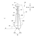
- FIG. 6 is a diagram for explaining the operation of the leg portion, and is a view obtained by rotating the lower knee portion by 180 ° in the leg portion shown in FIG. 5.
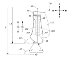
- FIG. 7 is an explanatory diagram of the operation of the leg portion, and is a view in which the lower knee is moved upward in the leg portion shown in FIG. 6.
- the form changing toy 10 of the embodiment is a doll body having a reversibly deformable structure, and is connected to a body part 11 and both left and right side surfaces of the lower part of the body part 11.
- the left and right leg portions 20, left and right arm portions 12 connected to the left and right side surfaces of the upper portion of the trunk portion 11, and a head portion 15 connected to the upper portion of the trunk portion 11 via a neck portion 13.
- the shape-changing toy 10 of the present embodiment has a telescopic portion on the left and right leg portions 20, and the length of each of the left and right leg portions 20 is adjustable.
- the user can change the shape changing toy 10 from one form shown in FIG. 1 to another form in which the length of the leg part 20 is different by changing the length of the leg part 20.
- the form which has an expansion / contraction part in the leg part 20 is demonstrated in this Embodiment, it is not limited to this, It can apply to the part which a form changes by extending / contracting, such as an arm part.
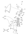
- the leg portion 20 is connected to the upper knee portion 30 connected to the trunk portion 11 via the connecting member 21, the lower knee portion 40 connected to the upper knee portion 30, and the lower end of the lower knee portion 40. It has a foot portion 22 to be connected, and a cover portion 23 that is attached to the upper knee portion 30 and covers the front side of the upper knee portion 30.
- the upper knee portion 30 includes a support portion 31 that rotatably supports the connecting member 21 and a shaft portion 32 that extends downward from the bottom surface of the support portion 31.
- the shaft portion 32 has a spherical portion 33 at a lower end portion (an end portion on a connected side).
- the spherical portion 33 has groove portions 36 ⁇ / b> F and R (first mating portions) formed along the axis 35 that is the longitudinal direction of the shaft portion 32 on the outer surface.
- the groove portions 36F, R are composed of a pair of left and right groove portions 36F and one groove portion 36R.
- the pair of left and right groove portions 36 ⁇ / b> F are provided on the front side (one side) of the axis 35 in the spherical portion 33.
- one groove portion 36R is provided on the rear side of the axis 35 (180 ° opposite to the pair of groove portions across the axis). *
- the knee lower part 40 is formed in a cylindrical shape by a pair of front and rear divided bodies. That is, the knee upper portion 30 is configured by a front half portion 41F that constitutes a front portion of the knee upper portion 30, and a rear half portion 41R that is fitted to face the front half portion 41F. Each of the front half portion 41F and the rear half portion 41R has a spherical holding portion 42F and a holding portion 42R at the upper end. Each of the front half 41F and the rear half 41R has a positioning hole 43F and a positioning projection 43R.
- the positioning hole 43F is aligned with the positioning projection 43R, and the spherical portion 33 is sandwiched from the front and rear by the holding portions 42F and R, so that the front half portion 41F and the rear half portion 41R are aligned.
- the spherical portion 33 is rotatably held at the upper end portion of the knee lower portion 40, so that when the knee lower portion 40 is arranged in series along the axis 35, The upper part 30 can be rotated about the axis 35.
- a notch 45 (see FIG. 3A) is further provided at the upper end of the rear half portion 41R, and the shaft portion 32 is fitted into the notch 45 so that the spherical portion 33 is used as a base point.
- the leg portion 20 is configured to be bendable. That is, the spherical portion 33 and the holding portions 42F, R, which are the connecting portions between the upper knee portion 30 and the lower knee portion 40, constitute a bendable knee joint.
- the lower knee portion 40 has convex portions 46F and R (second mating portions) extending along the axis 35 on the inner surface.
- the convex portions 46F, R are composed of one convex portion 46F and a pair of convex portions 46R.
- One protrusion 46F is formed in a shape that can be fitted into one groove 36R in the direction along the axis 35, and is provided on the inner surface on the front half 41F side (one side of the axis).
- the pair of convex portions 46R are formed in a shape that can be fitted into the pair of groove portions 36F in the direction along the axis 35, and are on the rear half portion 41R side (on the opposite side 180 ° with respect to the single convex portion). Provided on the inner surface.
- the movable position is set. That is, the lower knee portion 40 is fixed in such a manner that the movement of the lower knee portion 40 along the axis 35 is prevented when the groove portions 36F, R and the convex portions 46F, R are not meshed with each other in the rotation direction about the axis 35.
- the movable portion is allowed to move along the axis 35.
- leg portion 20 formed by the groove portions 36F, R and the convex portions 46F, 46R will be described with reference to FIGS. *
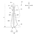
- the knee lower portion 40 faces the direction in which the front half 41F is located on the front side, and is in a fixed position.
- the groove portions 36F, R and the convex portions 46F, R are not engaged with each other, and the convex portions 46F, R have an end face 47 (see FIG. 3A) on the upper side in the longitudinal direction on the outer surface of the spherical portion 33.
- it functions as a stopper that prevents movement (upward movement) of the lower knee portion 40 along the axis 35.
- the length of the leg portion 20 is fixed, and the leg portion 20 is maintained in the most extended state.
- the user moves the knee lower portion 40 upward so that the knee upper portion 30 is accommodated in the knee lower portion 40 while the knee lower portion 40 is accommodated in the cover portion 23. be able to.
- the leg 20 can be shortened from the length L1 to the length L2 (arrow (2)), or the leg 20 can be freely expanded and contracted (arrow (3)) in the range of the lengths L2 to L1. It becomes possible.
- the convex portions 46R, F function as a guide for smoothly moving the lower knee portion 40 along the axis 35 by being engaged with and guided by the grooves 36F, R. *
- the lower knee 40 may be rotatable about the axis 35 in a state where the arm is moved upward, that is, in a state where the leg portion 20 is most contracted to the length L2. In this case, after the leg portion 20 is most contracted, the front half portion 41F of the lower knee portion 40 can be directed to the front side again.
- the lower knee 40 when the lower knee 40 is in the movable position, the lower knee 40 can be moved along the axis 35 with respect to the upper knee 30. Thereby, the user can change the toy form 10 from one form (refer FIG. 1) to another form (refer FIG. 7) from which the length of the leg part 20 differs easily, and can enjoy it. *
- the lower knee portion 40 is prevented from moving along the axis 35 when in the fixed position. For this reason, it can prevent that the shape change toy 10 returns to an original form naturally because a user rotates the knee lower part 40 to a fixed position.
- the expansion-contraction part of the shape change toy 10 can be comprised with the simple structure which has the knee upper part 30 and the knee lower part 40 as a main element.
- the convex portions 46F and R serve both as a stopper for preventing the movement of the lower knee 40 and a function as a guide for guiding the movement of the lower knee 40, the structure can be further simplified. Can do. *
- the number and arrangement of the convex portions 46F, R and the groove portions 36F, R can be arbitrarily changed, and the convex portions and the groove portions are respectively provided in at least two locations of the first member and the second member, Only the corresponding convex portions and groove portions are fitted to each other to allow sliding of the first member and the second member, and the non-corresponding convex portions and groove portions are not fitted to each other, and the first member and the second member are fitted.
- the first mating portion is configured by the grooves 36F and R
- the second mating portion is configured by the convex portions 46F and R.
- the first mating portion is configured by the convex portion, You may comprise a 2nd mating part by a groove part. *
- the form which provides an expansion-contraction part in a leg part was demonstrated in this Embodiment, it is not restricted to this, In addition to the leg part 20, the neck part 13 which connects the trunk
- the present invention is applied to a doll body has been described.
- the present invention can be applied to various models imitating animals, monsters, robots, vehicles, and the like in addition to doll bodies.
Landscapes
- Toys (AREA)
Abstract
【課題】 形態変化を簡単に楽しむことができると共に元の形態に戻りにくく、しかも、簡単な構造で構成できる形態変化玩具を提供する。【解決手段】 形態変化玩具は、長さが調整可能な脚部20を有する。脚部20は、膝上部30と、膝上部30に連結されると共に、膝上部30の軸線35に沿って直列配置されたときに軸線35を中心に膝上部30に対して回転可能な膝下部40と、を有する。膝下部40には、軸線35を中心とした回転方向において、軸線35に沿う膝下部40の移動が阻止され、脚部20の長さが固定される固定位置と、軸線35に沿う膝下部40の移動が許容され、脚部20の長さが調整可能となる可動位置と、が設定される。
Description
本発明は、形態変化玩具に関する。
従来、変形可能な構造を有する形態変化玩具に関し、各種の技術が提案されている(例えば、特許文献1参照)。
特許文献1には、前部材と後部材とを折り曲げ自在に連結すると共に、前部材の下面と後部材の下面を連結リンクによって回動自在に連結してなる形態変化玩具が開示される。連結リンクの端部には、ギアが設けられ、後部材には、前後方向に移動可能なスライド部材が設けられる。ギアは、スライド部材のラックに噛み合っている。
この特許文献1によれば、スライド部材を前方にスライドさせると、ラック、ギアおよび連結リンクによって、前部材が後部材側に折り曲げられるので、例えば、形態変化玩具をジェット機の形態からロボットの形態に簡単に変化させることができる。
しかしながら、特許文献1の形態変化玩具においては、簡単に形態変化玩具が変化する分、元に戻り易いという問題点がある。また、ラック、ギアおよび連結リンクなどの多くの構成部品が必要であり、構造が複雑である。
本発明は、形態変化を簡単に楽しむことができると共に元の形態に戻りにくく、しかも、簡単な構造で構成できる形態変化玩具を提供することにある。
本発明は、変形可能な構造を有する形態変化玩具であって、長さが調整可能な伸縮部を有し、前記伸縮部は、第1の部材と、前記第1の部材に対して回転可能に連結され、かつ前記第1の部材の長手方向に沿って摺動可能な第2の部材と、を有し、前記第2の部材は、前記第1の部材に対する前記第2の部材の摺動が阻止される固定位置と、前記第2の部材を前記第1の部材に対して回転させたとき、前記第1の部材に対する前記第2の部材の摺動が許容される可動位置と、の間を移動可能である。
本発明において、前記第2の部材は、前記固定位置から前記第2の部材を前記第1の部材に対して180°回転したとき、前記可動位置に位置することが好ましい。
本発明において、前記第1の部材は、第1の合わせ部を有し、前記第2の部材は、前記可動位置にあるとき前記第1の合わせ部と嵌合可能な第2の合わせ部を有することが好ましい。また、本発明において、前記第1の合わせ部は、前記第1の部材の長手方向に沿って設けられた溝部であり、前記第2の合わせ部は、前記第2の部材の長手方向に沿って設けられた凸部であることが好ましい。
本発明において、前記第1の部材は、前記第2の部材と連結される側の端部に球状部を有し、前記球状部に前記溝部が設けられており、前記第2の部材は、筒状に形成されて前記球状部を回転可能に保持し、前記凸部は、前記第2の部材が前記固定位置にあるとき、前記球状部に当接し、前記第2の部材が前記可動位置にあるとき、前記溝部と嵌合することが好ましい。
本発明において、前記溝部は、少なくとも第1の溝部と第2の溝部とを有し、前記凸部は、少なくとも第1の凸部と第2の凸部とを有し、前記第1の溝部と前記第1の凸部は嵌合可能であり、前記第2の溝部と前記第2の凸部は嵌合可能であることが好ましい。また、本発明において、前記第1の溝部は、前記第1の部材の長手方向に沿って設けられた2本の溝部であり、前記第2の溝部は、前記2本の溝部とずれた位置に設けられた1本の溝部であり、前記第1の凸部は、前記第2の部材の長手方向に沿って設けられた2本の凸部であり、前記第2の凸部は、前記一本の凸部とずれた位置に設けられた2本の凸部であることが好ましい。
本発明において、前記形態変化玩具は、第1の形態から第2の形態に変形可能であることが好ましい。また、本発明において、前記第1の部材と前記第2の部材との連結部は、人形体の関節であることが好ましい。
本発明によれば、形態変化を簡単に楽しむことができると共に元の形態に戻りにくく、しかも、簡単な構造で構成できる形態変化玩具を提供することができる。
(実施形態) 以下、添付図面を参照して、本発明を実施するための形態(以下、「実施形態」と称する)について説明する。実施形態の説明の全体を通して同じ要素には同じ番号を付している。
(形態変化玩具10の全体構成) まず、形態変化玩具10の全体構成を図1に基づいて説明する。図1に示すように、実施形態の形態変化玩具10は、可逆的に変形可能な構造を有する人形体であって、胴部11と、この胴部11の下部の左右両側面に連結される左右の脚部20と、胴部11の上部の左右両側面に連結される左右の腕部12と、胴部11の上部に首部13を介して連結される頭部15とを有する。
本実施の形態の形態変化玩具10は、左右の脚部20に伸縮部を有し、左右の脚部20のそれぞれは、長さが調整可能である。使用者は、脚部20の長さを変化させることで、形態変化玩具10を図1に示される一つの形態から、脚部20の長さが異なる別の形態に変化させることができる。なお、本実施の形態では、脚部20に伸縮部を有する形態を説明するが、これに限定するものではなく、腕部分など伸縮することにより形態が変化する部分に適用可能である。また、人形体等の第1の形態から、例えば飛行機等の第2の形態に変形可能な形態変化玩具にも適用可能である。
次に、脚部20の構成を図2~図4に基づいて説明する。図2に示すように、脚部20は、連結部材21を介して胴部11に連結される膝上部30と、この膝上部30に連結される膝下部40と、この膝下部40の下端に連結される足部22と、膝上部30に取り付けられ膝上部30の前側を覆うカバー部23とを有する。
膝上部30は、連結部材21を回転可能に支持する支持部31と、この支持部31の底面から下方に延びる軸部32とを有する。この軸部32は、球状部33を下端部(連結される側の端部)に有する。
図3(a)に示すように、この球状部33は、軸部32の長手方向である軸線35に沿って形成される溝部36F,R(第1の合わせ部)を外面に有する。溝部36F,Rは、左右一対の溝部36Fと、一つの溝部36Rとからなる。左右一対の溝部36Fは、球状部33において、軸線35の前側(一側)に設けられる。また、一つの溝部36Rは、軸線35の後側(一対の溝部に対して軸線を挟んで180°反対側)に設けられる。
(膝下部40の構成) 膝下部40は、前後一対の分割体によって筒状に形成される。すなわち、膝上部30は、膝上部30の前部を構成する前半部41Fと、この前半部41Fと対向して嵌合する後半部41Rとによって構成される。前半部41Fおよび後半部41Rのそれぞれは、球面状の保持部42Fおよび保持部42Rを上端部に有する。また、前半部41Fおよび後半部41Rのそれぞれは、位置決め穴43Fおよび位置決め突起43Rを有する。膝上部30と膝下部40との連結に際しては、位置決め穴43Fを位置決め突起43Rに合わせ、保持部42F,Rで球状部33を前後から挟むようにして、前半部41Fと後半部41Rとを合わせる。
これにより、図3(b)に示すように、膝下部40の上端部に球状部33が回転可能に保持されるので、膝下部40は、軸線35に沿って直列配置されたときに、膝上部30に対して軸線35を中心に回転可能となる。
この例では、さらに、後半部41Rの上端に切り欠き45(図3(a)参照)が設けられており、この切り欠き45に軸部32を嵌合させることで、球状部33を基点に脚部20が折り曲げ可能に構成されている。すなわち、膝上部30と膝下部40との連結部である球状部33および保持部42F,Rは、折り曲げ可能な膝関節を構成する。
また、図3(a)に示すように、膝下部40は、軸線35に沿って延びる凸部46F,R(第2の合わせ部)を内面に有する。凸部46F,Rは、一つの凸部46Fと一対の凸部46Rとからなる。一つの凸部46Fは、軸線35に沿う方向において、一つの溝部36Rに嵌合可能な形状に形成され、前半部41F側(軸線の一側)の内面に設けられる。一対の凸部46Rは、軸線35に沿う方向において、一対の溝部36Fに嵌合可能な形状に形成され、後半部41R側(一つの凸部に対して軸線を挟んで180°反対側)の内面に設けられる。
膝下部40には、凸部46F,Rと溝部36F,Rとの相対位置によって、脚部20の長さが固定される(調整できない)固定位置と、脚部20の長さが調整可能な可動位置とが設定される。すなわち、膝下部40は、軸線35を中心とした回転方向において、溝部36F,Rと凸部46F,Rとが互いに噛み合っていない状態では、軸線35に沿う膝下部40の移動が阻止される固定位置となり、溝部36F,Rと凸部46F,Rとが互いに噛み合う状態では、軸線35に沿う膝下部40の移動が許容される可動位置となる。
本実施形態では、図4(a)に示すように、前半部41Fが前側に位置する方向に膝下部40が向いたときは、一つの溝部36Rと一つの凸部46F、および、一対の溝部36Fと一対の凸部46Rは、それぞれ、互いに噛み合っておらず、膝下部40は、固定位置にある。一方、図4(b)に示すように、前半部41Fを後側に位置させる方向に膝下部40が回転したときは、一つの溝部36Rと一つの凸部46F、および、一対の溝部36Fと一対の凸部46Rは、それぞれ、互いに噛み合って嵌合するため、膝下部40は、可動位置となる。
続いて、溝部36F,Rおよび凸部46F,Rによる脚部20について図5~図7に基づいて説明する。
図5において、膝下部40は、前半部41Fが前側に位置する方向に向いており、固定位置にある。この状態では、溝部36F,Rと凸部46F,Rとが噛み合っておらず、凸部46F,Rは、その長手方向上側の端面47(図3(a)参照)が球状部33の外面に当接することで、軸線35に沿う膝下部40の移動(上方への移動)を阻止するストッパとして機能している。その結果、脚部20は、長さL1が固定され、最も伸びた状態に維持される。
この状態から、図6に示すように、前半部41Fが後側に位置するように、軸線35を中心に膝下部40を180°回転させると(矢印(1))、溝部36F,Rと凸部46R,Fとが噛み合い(図4(b)参照)、膝下部40が可動位置になる。この状態では、軸線35に沿う膝下部40の移動(上方への移動)が許容される。
これにより、図7に示すように、使用者は、カバー部23内に膝下部40を収納させながら、膝下部40内に膝上部30を収納させるようにして、膝下部40を上方に移動させることができる。その結果、脚部20を長さL1から長さL2に縮めたり(矢印(2))、長さL2~L1の範囲において脚部20を自由に伸縮したり(矢印(3))することが可能になる。このとき、凸部46R,Fは、溝部36F,Rに噛み合って嵌合・案内されることで、軸線35に沿って膝下部40を円滑に移動させるガイドとして機能している。
なお、膝下部40
を最も上方に移動させた状態、すなわち、脚部20が長さL2に最も縮められた状態において、軸線35を中心に膝下部40を回転可能としてもよい。この場合、脚部20を最も縮めた後に、膝下部40の前半部41Fを再度、前側に向けることができる。
を最も上方に移動させた状態、すなわち、脚部20が長さL2に最も縮められた状態において、軸線35を中心に膝下部40を回転可能としてもよい。この場合、脚部20を最も縮めた後に、膝下部40の前半部41Fを再度、前側に向けることができる。
本実施の形態における形態変化玩具10では、膝下部40が可動位置にあるときは、膝上部30に対して膝下部40を軸線35に沿って移動することができる。これにより、使用者は、形態変化玩具10を一つの形態(図1参照)から、脚部20の長さが異なる別の形態(図7参照)に簡単に変化させて、楽しむことができる。
一方、膝下部40は、固定位置にあるときは、軸線35に沿って移動することが阻止される。このため、使用者が膝下部40を固定位置に回転させておくことで、形態変化玩具10が元の形態に自然に戻ってしまうことを防ぐことができる。また、膝上部30および膝下部40を主要素とする簡単な構造で、形態変化玩具10の伸縮部を構成することができる。
したがって、本実施形態によれば、形態変化を簡単に楽しむことができると共に元の形態に戻りにくく、しかも、簡単な構造で構成できる形態変化玩具10を提供することができる。
また、凸部46F,Rが、膝下部40の移動を阻止するストッパとしての機能と、膝下部40の移動を案内するガイドとしての機能とを兼用するため、構造の更なる簡素化を図ることができる。
以上、実施形態を用いて本発明を説明したが、本発明の技術的範囲は上記実施形態に記載の範囲には限定されないことは言うまでもない。上記実施形態に、多様な変更または改良を加えることが可能である。
例えば、凸部46F,R、溝部36F,Rのそれぞれの個数および配置は、任意に変更可能であり、凸部および溝部はそれぞれ第1の部材と第2の部材の少なくとも2箇所に設けられ、それぞれ対応する凸部および溝部同士のみが嵌合して第1の部材と第2の部材の摺動を許容し、対応しない凸部および溝部同士は嵌合せず第1の部材と第2の部材の摺動を阻止する形状になっていれば特に限定されるものではない。また、本実施の形態では、第1の合わせ部を溝部36F,Rで構成し、第2の合わせ部を凸部46F,Rで構成したが、第1の合わせ部を凸部で構成し、第2の合わせ部を溝部で構成してもよい。
また、本実施の形態では脚部に伸縮部を設ける形態について説明したがこれに限られるものではなく、脚部20の他、胴部11と頭部15を連結する首部13や、腕部12、胴部11の腰など、伸縮させたい人形体の任意の部位に適用可能である。また、実施形態では、本発明を人形体に適用した例を示したが、本発明は、人形体の他、動物や怪獣、ロボット、乗り物などを模した各種の模型に適用可能である。
10 形態変化玩具20 脚部30 膝上部33 球状部36F 一対の溝部36R 一つの溝部40 膝下部46F 一つの凸部46R 一対の凸部L1 長さL2 長さ
Claims (9)
- 変形可能な構造を有する形態変化玩具であって、 長さが調整可能な伸縮部を有し、 前記伸縮部は、 第1の部材と、 前記第1の部材に対して回転可能に連結され、かつ前記第1の部材の長手方向に沿って摺動可能な第2の部材と、 を有し、 前記第2の部材は、前記第1の部材に対する前記第2の部材の摺動が阻止される固定位置と、前記第2の部材を前記第1の部材に対して回転させたとき、前記第1の部材に対する前記第2の部材の摺動が許容される可動位置と、の間を移動可能である形態変化玩具。
- 請求項1において、 前記第2の部材は、前記固定位置から前記第2の部材を前記第1の部材に対して180°回転したとき、前記可動位置に位置する形態変化玩具。
- 請求項1または請求項2において、 前記第1の部材は、第1の合わせ部を有し、 前記第2の部材は、前記可動位置にあるとき前記第1の合わせ部と嵌合可能な第2の合わせ部を有する形態変化玩具。
- 請求項3において、 前記第1の合わせ部は、前記第1の部材の長手方向に沿って設けられた溝部であり、 前記第2の合わせ部は、前記第2の部材の長手方向に沿って設けられた凸部である形態変化玩具。
- 請求項4において、 前記第1の部材は、 前記第2の部材と連結される側の端部に球状部を有し、前記球状部に前記溝部が設けられており、 前記第2の部材は、 筒状に形成されて前記球状部を回転可能に保持し、 前記凸部は、 前記第2の部材が前記固定位置にあるとき、前記球状部に当接し、前記第2の部材が前記可動位置にあるとき、前記溝部と嵌合する形態変化玩具。
- 請求項5または請求項6において、前記溝部は、少なくとも第1の溝部と第2の溝部とを有し、前記凸部は、少なくとも第1の凸部と第2の凸部とを有し、前記第1の溝部と前記第1の凸部は嵌合可能であり、前記第2の溝部と前記第2の凸部は嵌合可能である形態変化玩具。
- 請求項6において、 前記第1の溝部は、前記第1の部材の長手方向に沿って設けられた2本の溝部であり、前記第2の溝部は、前記2本の溝部とずれた位置に設けられた1本の溝部であり、 前記第1の凸部は、前記第2の部材の長手方向に沿って設けられた2本の凸部であり、前記第2の凸部は、前記2本の凸部とずれた位置に設けられた1本の凸部である形態変化玩具。
- 請求項1乃至請求項7のいずれか一項において、 前記形態変化玩具は、第1の形態から第2の形態に変形可能である形態変化玩具。
- 請求項1乃至請求項8のいずれか一項において、 前記第1の部材と前記第2の部材との連結部は、人形体の関節である形態変化玩具。
Priority Applications (2)
| Application Number | Priority Date | Filing Date | Title |
|---|---|---|---|
| CN201480005711.6A CN104936668B (zh) | 2013-03-22 | 2014-01-15 | 形态变化玩具 |
| HK15111716.3A HK1210981B (en) | 2013-03-22 | 2014-01-15 | Transformable toy |
Applications Claiming Priority (2)
| Application Number | Priority Date | Filing Date | Title |
|---|---|---|---|
| JP2013059767A JP5650266B2 (ja) | 2013-03-22 | 2013-03-22 | 形態変化玩具 |
| JP2013-059767 | 2013-03-22 |
Publications (1)
| Publication Number | Publication Date |
|---|---|
| WO2014148073A1 true WO2014148073A1 (ja) | 2014-09-25 |
Family
ID=51579770
Family Applications (1)
| Application Number | Title | Priority Date | Filing Date |
|---|---|---|---|
| PCT/JP2014/050518 Ceased WO2014148073A1 (ja) | 2013-03-22 | 2014-01-15 | 形態変化玩具 |
Country Status (3)
| Country | Link |
|---|---|
| JP (1) | JP5650266B2 (ja) |
| CN (1) | CN104936668B (ja) |
| WO (1) | WO2014148073A1 (ja) |
Cited By (3)
| Publication number | Priority date | Publication date | Assignee | Title |
|---|---|---|---|---|
| JP7023336B1 (ja) | 2020-09-07 | 2022-02-21 | 株式会社バンダイ | パーツ連結構造及び人形玩具 |
| CN115350480A (zh) * | 2022-05-10 | 2022-11-18 | 株式会社万代 | 模型玩具和关节构造 |
| CN117244257A (zh) * | 2022-06-09 | 2023-12-19 | 北京电子科技职业学院 | 一种青蛙与蝌蚪形态切换玩具 |
Families Citing this family (4)
| Publication number | Priority date | Publication date | Assignee | Title |
|---|---|---|---|---|
| JP6481013B1 (ja) * | 2017-11-14 | 2019-03-13 | 株式会社バンダイ | 変形玩具、及び変形玩具セット |
| JP6796110B2 (ja) * | 2018-06-29 | 2020-12-02 | 株式会社バンダイ | 腕構造及び人型玩具 |
| JP7168806B1 (ja) * | 2022-03-11 | 2022-11-09 | 株式会社バンダイ | 模型玩具、及び可動構造 |
| JP7293478B1 (ja) * | 2022-09-28 | 2023-06-19 | 株式会社バンダイ | 模型玩具 |
Citations (3)
| Publication number | Priority date | Publication date | Assignee | Title |
|---|---|---|---|---|
| JPS6256095U (ja) * | 1985-09-30 | 1987-04-07 | ||
| JPS6259090U (ja) * | 1985-09-30 | 1987-04-13 | ||
| JPS6259091U (ja) * | 1985-09-30 | 1987-04-13 |
Family Cites Families (6)
| Publication number | Priority date | Publication date | Assignee | Title |
|---|---|---|---|---|
| JP3198094B2 (ja) * | 1998-10-30 | 2001-08-13 | 株式会社バンダイ | 変身玩具 |
| US7326100B2 (en) * | 2005-02-18 | 2008-02-05 | O'brien Gilford | Marble building toy |
| CN201701737U (zh) * | 2010-02-24 | 2011-01-12 | 杜素东 | 变形游戏玩具 |
| CN201959555U (zh) * | 2010-04-29 | 2011-09-07 | 浙江中南卡通股份有限公司 | 一种可变形的遁地鼠玩具 |
| US9993739B2 (en) * | 2010-12-21 | 2018-06-12 | David Weeks Studio LLC | Transformable toy robot |
| CN102416265A (zh) * | 2011-09-09 | 2012-04-18 | 周剑 | 变形金刚机器人玩具及方法 |
-
2013
- 2013-03-22 JP JP2013059767A patent/JP5650266B2/ja active Active
-
2014
- 2014-01-15 CN CN201480005711.6A patent/CN104936668B/zh active Active
- 2014-01-15 WO PCT/JP2014/050518 patent/WO2014148073A1/ja not_active Ceased
Patent Citations (3)
| Publication number | Priority date | Publication date | Assignee | Title |
|---|---|---|---|---|
| JPS6256095U (ja) * | 1985-09-30 | 1987-04-07 | ||
| JPS6259090U (ja) * | 1985-09-30 | 1987-04-13 | ||
| JPS6259091U (ja) * | 1985-09-30 | 1987-04-13 |
Cited By (6)
| Publication number | Priority date | Publication date | Assignee | Title |
|---|---|---|---|---|
| JP7023336B1 (ja) | 2020-09-07 | 2022-02-21 | 株式会社バンダイ | パーツ連結構造及び人形玩具 |
| WO2022050112A1 (ja) * | 2020-09-07 | 2022-03-10 | 株式会社バンダイ | パーツ連結構造及び人形玩具 |
| JP2022044151A (ja) * | 2020-09-07 | 2022-03-17 | 株式会社バンダイ | パーツ連結構造及び人形玩具 |
| CN115350480A (zh) * | 2022-05-10 | 2022-11-18 | 株式会社万代 | 模型玩具和关节构造 |
| CN115350480B (zh) * | 2022-05-10 | 2024-03-08 | 株式会社万代 | 模型玩具和关节构造 |
| CN117244257A (zh) * | 2022-06-09 | 2023-12-19 | 北京电子科技职业学院 | 一种青蛙与蝌蚪形态切换玩具 |
Also Published As
| Publication number | Publication date |
|---|---|
| HK1210981A1 (en) | 2016-05-13 |
| JP5650266B2 (ja) | 2015-01-07 |
| CN104936668B (zh) | 2017-03-08 |
| JP2014183913A (ja) | 2014-10-02 |
| CN104936668A (zh) | 2015-09-23 |
Similar Documents
| Publication | Publication Date | Title |
|---|---|---|
| JP5650266B2 (ja) | 形態変化玩具 | |
| CN108472549B (zh) | 人形玩具 | |
| WO2014129065A1 (ja) | 人形体 | |
| JP7129217B2 (ja) | 人形の腰部関節構造及び人形 | |
| JP7839042B2 (ja) | 玩具部品及び人形玩具 | |
| WO2014054339A1 (ja) | 人形体の手首の関節構造、人形体の足首の関節構造、および人形体 | |
| JP6030615B2 (ja) | 人形玩具の肩関節構造及び人形玩具 | |
| JP2025036051A (ja) | 模型玩具及び関節構造体 | |
| JP2024118402A (ja) | 模型玩具及び関節構造体 | |
| JP5661873B1 (ja) | 模型キット | |
| JP5025033B1 (ja) | 玩具体におけるカバー部材の動作構造および玩具体 | |
| JP6072738B2 (ja) | 形態変化玩具 | |
| JP7023336B1 (ja) | パーツ連結構造及び人形玩具 | |
| JP6703637B1 (ja) | 可動構造および玩具 | |
| JP7832971B2 (ja) | 人型玩具 | |
| JP2009034232A (ja) | 人形体 | |
| JP7590360B2 (ja) | 玩具部品及び人形玩具 | |
| HK1210981B (en) | Transformable toy | |
| JP7462493B2 (ja) | 連結パーツ、インジェクションキットおよび人型玩具 | |
| JP2024162123A (ja) | 模型玩具、及び模型玩具の構造体 | |
| US9636595B2 (en) | Toy figures with expandable articulating joints | |
| JP6411429B2 (ja) | 人形玩具の肩関節構造及び人形玩具 | |
| JP2013006028A (ja) | 玩具体におけるカバー部材の動作構造および玩具体 | |
| JP6069233B2 (ja) | 人形体の手首の関節構造、人形体の足首の関節構造、および人形体 | |
| CN212914504U (zh) | 一种可隐藏肢体的多形态转动变形玩具 |
Legal Events
| Date | Code | Title | Description |
|---|---|---|---|
| 121 | Ep: the epo has been informed by wipo that ep was designated in this application |
Ref document number: 14768493 Country of ref document: EP Kind code of ref document: A1 |
|
| NENP | Non-entry into the national phase |
Ref country code: DE |
|
| 122 | Ep: pct application non-entry in european phase |
Ref document number: 14768493 Country of ref document: EP Kind code of ref document: A1 |