WO2014141834A1 - Battery pack, electrical device, and control method therefor - Google Patents
Battery pack, electrical device, and control method therefor Download PDFInfo
- Publication number
- WO2014141834A1 WO2014141834A1 PCT/JP2014/053866 JP2014053866W WO2014141834A1 WO 2014141834 A1 WO2014141834 A1 WO 2014141834A1 JP 2014053866 W JP2014053866 W JP 2014053866W WO 2014141834 A1 WO2014141834 A1 WO 2014141834A1
- Authority
- WO
- WIPO (PCT)
- Prior art keywords
- battery
- battery unit
- unit
- life
- battery pack
- Prior art date
Links
Images

Classifications
-
- G—PHYSICS
- G01—MEASURING; TESTING
- G01R—MEASURING ELECTRIC VARIABLES; MEASURING MAGNETIC VARIABLES
- G01R31/00—Arrangements for testing electric properties; Arrangements for locating electric faults; Arrangements for electrical testing characterised by what is being tested not provided for elsewhere
- G01R31/36—Arrangements for testing, measuring or monitoring the electrical condition of accumulators or electric batteries, e.g. capacity or state of charge [SoC]
- G01R31/392—Determining battery ageing or deterioration, e.g. state of health
-
- H—ELECTRICITY
- H01—ELECTRIC ELEMENTS
- H01M—PROCESSES OR MEANS, e.g. BATTERIES, FOR THE DIRECT CONVERSION OF CHEMICAL ENERGY INTO ELECTRICAL ENERGY
- H01M10/00—Secondary cells; Manufacture thereof
- H01M10/42—Methods or arrangements for servicing or maintenance of secondary cells or secondary half-cells
- H01M10/425—Structural combination with electronic components, e.g. electronic circuits integrated to the outside of the casing
-
- H—ELECTRICITY
- H01—ELECTRIC ELEMENTS
- H01M—PROCESSES OR MEANS, e.g. BATTERIES, FOR THE DIRECT CONVERSION OF CHEMICAL ENERGY INTO ELECTRICAL ENERGY
- H01M10/00—Secondary cells; Manufacture thereof
- H01M10/42—Methods or arrangements for servicing or maintenance of secondary cells or secondary half-cells
- H01M10/48—Accumulators combined with arrangements for measuring, testing or indicating the condition of cells, e.g. the level or density of the electrolyte
- H01M10/482—Accumulators combined with arrangements for measuring, testing or indicating the condition of cells, e.g. the level or density of the electrolyte for several batteries or cells simultaneously or sequentially
-
- H—ELECTRICITY
- H01—ELECTRIC ELEMENTS
- H01M—PROCESSES OR MEANS, e.g. BATTERIES, FOR THE DIRECT CONVERSION OF CHEMICAL ENERGY INTO ELECTRICAL ENERGY
- H01M10/00—Secondary cells; Manufacture thereof
- H01M10/42—Methods or arrangements for servicing or maintenance of secondary cells or secondary half-cells
- H01M10/48—Accumulators combined with arrangements for measuring, testing or indicating the condition of cells, e.g. the level or density of the electrolyte
- H01M10/486—Accumulators combined with arrangements for measuring, testing or indicating the condition of cells, e.g. the level or density of the electrolyte for measuring temperature
-
- H—ELECTRICITY
- H01—ELECTRIC ELEMENTS
- H01M—PROCESSES OR MEANS, e.g. BATTERIES, FOR THE DIRECT CONVERSION OF CHEMICAL ENERGY INTO ELECTRICAL ENERGY
- H01M10/00—Secondary cells; Manufacture thereof
- H01M10/60—Heating or cooling; Temperature control
- H01M10/63—Control systems
-
- H—ELECTRICITY
- H01—ELECTRIC ELEMENTS
- H01M—PROCESSES OR MEANS, e.g. BATTERIES, FOR THE DIRECT CONVERSION OF CHEMICAL ENERGY INTO ELECTRICAL ENERGY
- H01M10/00—Secondary cells; Manufacture thereof
- H01M10/60—Heating or cooling; Temperature control
- H01M10/63—Control systems
- H01M10/633—Control systems characterised by algorithms, flow charts, software details or the like
-
- H—ELECTRICITY
- H02—GENERATION; CONVERSION OR DISTRIBUTION OF ELECTRIC POWER
- H02J—CIRCUIT ARRANGEMENTS OR SYSTEMS FOR SUPPLYING OR DISTRIBUTING ELECTRIC POWER; SYSTEMS FOR STORING ELECTRIC ENERGY
- H02J7/00—Circuit arrangements for charging or depolarising batteries or for supplying loads from batteries
- H02J7/0047—Circuit arrangements for charging or depolarising batteries or for supplying loads from batteries with monitoring or indicating devices or circuits
- H02J7/0048—Detection of remaining charge capacity or state of charge [SOC]
- H02J7/0049—Detection of fully charged condition
-
- H—ELECTRICITY
- H02—GENERATION; CONVERSION OR DISTRIBUTION OF ELECTRIC POWER
- H02J—CIRCUIT ARRANGEMENTS OR SYSTEMS FOR SUPPLYING OR DISTRIBUTING ELECTRIC POWER; SYSTEMS FOR STORING ELECTRIC ENERGY
- H02J7/00—Circuit arrangements for charging or depolarising batteries or for supplying loads from batteries
- H02J7/0047—Circuit arrangements for charging or depolarising batteries or for supplying loads from batteries with monitoring or indicating devices or circuits
- H02J7/005—Detection of state of health [SOH]
-
- H—ELECTRICITY
- H02—GENERATION; CONVERSION OR DISTRIBUTION OF ELECTRIC POWER
- H02J—CIRCUIT ARRANGEMENTS OR SYSTEMS FOR SUPPLYING OR DISTRIBUTING ELECTRIC POWER; SYSTEMS FOR STORING ELECTRIC ENERGY
- H02J7/00—Circuit arrangements for charging or depolarising batteries or for supplying loads from batteries
- H02J7/0063—Circuit arrangements for charging or depolarising batteries or for supplying loads from batteries with circuits adapted for supplying loads from the battery
-
- H—ELECTRICITY
- H02—GENERATION; CONVERSION OR DISTRIBUTION OF ELECTRIC POWER
- H02J—CIRCUIT ARRANGEMENTS OR SYSTEMS FOR SUPPLYING OR DISTRIBUTING ELECTRIC POWER; SYSTEMS FOR STORING ELECTRIC ENERGY
- H02J7/00—Circuit arrangements for charging or depolarising batteries or for supplying loads from batteries
- H02J7/007—Regulation of charging or discharging current or voltage
- H02J7/007188—Regulation of charging or discharging current or voltage the charge cycle being controlled or terminated in response to non-electric parameters
- H02J7/007192—Regulation of charging or discharging current or voltage the charge cycle being controlled or terminated in response to non-electric parameters in response to temperature
- H02J7/007194—Regulation of charging or discharging current or voltage the charge cycle being controlled or terminated in response to non-electric parameters in response to temperature of the battery
-
- H—ELECTRICITY
- H01—ELECTRIC ELEMENTS
- H01M—PROCESSES OR MEANS, e.g. BATTERIES, FOR THE DIRECT CONVERSION OF CHEMICAL ENERGY INTO ELECTRICAL ENERGY
- H01M10/00—Secondary cells; Manufacture thereof
- H01M10/05—Accumulators with non-aqueous electrolyte
- H01M10/052—Li-accumulators
- H01M10/0525—Rocking-chair batteries, i.e. batteries with lithium insertion or intercalation in both electrodes; Lithium-ion batteries
-
- H—ELECTRICITY
- H01—ELECTRIC ELEMENTS
- H01M—PROCESSES OR MEANS, e.g. BATTERIES, FOR THE DIRECT CONVERSION OF CHEMICAL ENERGY INTO ELECTRICAL ENERGY
- H01M10/00—Secondary cells; Manufacture thereof
- H01M10/42—Methods or arrangements for servicing or maintenance of secondary cells or secondary half-cells
- H01M10/425—Structural combination with electronic components, e.g. electronic circuits integrated to the outside of the casing
- H01M2010/4271—Battery management systems including electronic circuits, e.g. control of current or voltage to keep battery in healthy state, cell balancing
-
- H—ELECTRICITY
- H01—ELECTRIC ELEMENTS
- H01M—PROCESSES OR MEANS, e.g. BATTERIES, FOR THE DIRECT CONVERSION OF CHEMICAL ENERGY INTO ELECTRICAL ENERGY
- H01M2220/00—Batteries for particular applications
- H01M2220/20—Batteries in motive systems, e.g. vehicle, ship, plane
-
- H—ELECTRICITY
- H02—GENERATION; CONVERSION OR DISTRIBUTION OF ELECTRIC POWER
- H02J—CIRCUIT ARRANGEMENTS OR SYSTEMS FOR SUPPLYING OR DISTRIBUTING ELECTRIC POWER; SYSTEMS FOR STORING ELECTRIC ENERGY
- H02J7/00—Circuit arrangements for charging or depolarising batteries or for supplying loads from batteries
- H02J7/0047—Circuit arrangements for charging or depolarising batteries or for supplying loads from batteries with monitoring or indicating devices or circuits
- H02J7/0048—Detection of remaining charge capacity or state of charge [SOC]
-
- Y—GENERAL TAGGING OF NEW TECHNOLOGICAL DEVELOPMENTS; GENERAL TAGGING OF CROSS-SECTIONAL TECHNOLOGIES SPANNING OVER SEVERAL SECTIONS OF THE IPC; TECHNICAL SUBJECTS COVERED BY FORMER USPC CROSS-REFERENCE ART COLLECTIONS [XRACs] AND DIGESTS
- Y02—TECHNOLOGIES OR APPLICATIONS FOR MITIGATION OR ADAPTATION AGAINST CLIMATE CHANGE
- Y02E—REDUCTION OF GREENHOUSE GAS [GHG] EMISSIONS, RELATED TO ENERGY GENERATION, TRANSMISSION OR DISTRIBUTION
- Y02E60/00—Enabling technologies; Technologies with a potential or indirect contribution to GHG emissions mitigation
- Y02E60/10—Energy storage using batteries
Definitions
- the present invention relates to a battery pack provided with secondary battery cells, and more particularly, to a battery pack provided with lithium ion secondary battery cells.
- a battery pack including a secondary battery cell such as a lithium ion secondary battery cell has been used as a power source for electric devices.
- the secondary battery cell provided in the battery pack deteriorates according to the elapsed time from manufacture, the number of cycles in which charging / discharging has been performed, and the full charge capacity of the secondary battery cell decreases as the deterioration progresses. .
- the deterioration of the secondary battery cell progresses to a certain extent, not only the full charge capacity decreases, but also the secondary battery cell swells or leaks, which has an adverse effect on the electrical equipment equipped with the battery pack. May have an effect.
- the full charge capacity is the maximum amount of power that can be stored in the secondary battery cell.
- the swelled secondary battery cell may press on a structural member (for example, a case) of an electric device and deform the structural member.
- a structural member for example, a case
- the electrolyte has conductivity, causing migration to the electronic component. As a result, electronic components may be deteriorated.
- the protection circuit of the battery pack measures the full charge capacity and DC resistance of the secondary battery cell, and predicts the deterioration state (SOH: State Of Health) of the secondary battery cell based on the measured value. Then, the protection circuit stops the use of the secondary battery cell based on the deterioration state before the secondary battery cell has an adverse effect on the electric device.
- SOH State Of Health
- the electric power supplied from the battery pack is used for driving a motor, but the motor is normally driven by pulse control. No constant current flows through Further, the current flowing through the battery pack changes depending on the traveling state such as whether or not the electrically assisted bicycle is traveling on a slope. Therefore, it is difficult to measure DC resistance.
- the temperature of the battery pack varies depending on the region, time zone, season, etc. where the electric assist bicycle is used, but the DC resistance of the battery pack increases as the battery pack cools, so the DC resistance is measured. Even if it is possible, it is very difficult to predict the deterioration state.
- the secondary battery is not always used until it is fully discharged from a fully charged state, and depending on the user, discharging and charging with a small charge / discharge amount are repeated. In such a case, it is difficult to measure the full charge capacity.
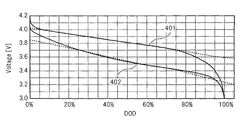
- FIG. 1 is a diagram for explaining in detail the cause of the above problem.
- a manganese spinel-based characteristic curve 401 showing a relationship between a discharge depth (DOD) and a discharge voltage (Voltage) in a manganese spinel-based lithium ion secondary battery cell, and a ternary lithium-ion secondary battery.
- a ternary characteristic curve 402 showing the relationship between the discharge depth and discharge voltage in the cell is shown.
- the ternary lithium ion secondary battery cell is a lithium ion secondary battery cell using cobalt (Co), nickel (Ni), and manganese as a positive electrode.
- the open circuit voltage is measured.
- the full charge capacity can be measured.
- the temperature and the discharge current of the battery pack are not always constant, and therefore, the voltage drop is not always constant when the secondary battery cell is energized with the electric device. For this reason, the measured value of the full charge capacity deviates from the actual value, and the full charge capacity cannot be accurately measured.
- the discharge voltage gradually decreases, and the measured value of the full charge capacity greatly deviates from the actual value due to a difference between the discharge voltage and the open circuit voltage. Therefore, it is very difficult to accurately measure the full charge capacity.
- the present invention has been made in view of the above-described problems, and an object of the present invention is to provide a battery pack, an electric device, and a control method thereof that can more accurately prevent adverse effects on the outside.
- the battery pack according to the present invention includes a battery unit including a secondary battery cell, and an index value related to a deterioration state of the battery unit, a capacity reduction rate which is a rate of reduction from an initial value of a full charge capacity of the battery unit, The number of cycles, which is the number of cycles in which the battery unit is charged until the cumulative value of the amount of charge charged in the battery unit reaches a predetermined charge amount, the number of times the battery unit has been charged, Whether or not the battery part has reached the end of its life by measuring at least two or more of the elapsed time since manufacture and the cell voltage, which is the voltage of the secondary battery cell, and using the measured index value And a stop unit that stops use of the battery unit when the battery unit reaches the end of its life.
- the electric device includes a battery pack.
- a method for controlling a battery pack according to the present invention is a method for controlling a battery pack having a battery unit having secondary battery cells, wherein an initial value of a full charge capacity of the battery unit is used as an index value regarding a deterioration state of the battery unit.
- a capacity reduction rate that is a rate of decrease from a value, a cycle number that is the number of cycles that the battery unit is charged until a cumulative value of a charge amount charged in the battery unit reaches a predetermined charge amount, the battery At least two or more of the number of times the part is charged, the elapsed time since the battery part was manufactured, and the cell voltage, which is the voltage between the two electrodes of the secondary battery cell, and the measured index value
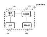
- FIG. 2 is a block diagram showing the configuration of the battery pack according to the embodiment of the present invention.
- the battery pack 100 includes a battery unit 1 and a protection unit (BMU: Battery Management Unit) 2.
- Battery pack 100 is connected to an electric device (not shown in FIG. 2) and functions as a power source for the electric device.
- the electric device is a moving body such as an electric assist bicycle, an electric motorcycle, and an electric automobile.
- the electrical device is not limited to a mobile object, and may be another device such as a mobile phone.
- the battery unit 1 includes a secondary battery cell (Cell) 11 that can be charged and discharged, a positive electrode terminal P, and a negative electrode terminal N.
- Cell secondary battery cell
- the battery unit 1 has a configuration in which a plurality of secondary battery cells 11 are connected in series.
- the battery part 1 may be comprised by the single secondary battery cell, and the structure by which the some secondary battery was connected in parallel or the matrix form may be sufficient. Note that the number and arrangement of the secondary battery cells are appropriately determined according to the type of the electrical device, the type of the secondary battery cell, and the like.
- the type of the secondary battery cell 11 is not particularly limited, but is, for example, a lithium ion secondary battery cell.
- the lithium ion secondary battery cell include a manganese spinel lithium ion secondary battery cell using manganese for the positive electrode and a ternary lithium ion battery cell using cobalt, nickel and manganese for the positive electrode.
- the protection unit 2 is connected to the battery unit 1 (specifically, the positive electrode terminal P and the negative electrode terminal N), and protects the electric device connected to the battery unit 1 and the battery pack 100.
- the protection unit 2 includes a discharge FET (Field transistor) 21, a charge FET22, a temperature sensor 23, a current detection unit 24, a monitoring IC (Integrated ⁇ Circuit) 25, and an MCU (Micro ControlMCUnit). 26. Further, the protection unit 2 includes a positive output terminal POUT and a negative output terminal NOUT for transmitting / receiving electric power to / from an electric device, and a communication terminal CX for communicating with the electric device. There may be a plurality of communication terminals CX.
- the discharge FET 21 is a switch for controlling the discharge current output from the battery unit 1
- the charge FET 22 is a switch for controlling the charge current supplied to the battery unit 1.
- the discharge FET 21 and the charge FET 22 are provided between the positive terminal P and the positive output terminal POUT of the battery unit 1, but between the negative terminal N and the negative output terminal NOUT of the battery unit 1. May be provided.
- a switch for controlling the discharge current and the charge current a breaker or a relay may be used instead of the FET.
- the temperature sensor 23 is a temperature detection unit that detects the temperature of the battery unit 1. There may be a plurality of temperature sensors 23. In this case, each of the temperature sensors 23 measures the temperature of a different part of the battery unit 1.
- the current detector 24 detects the charging current and discharging current of the battery unit 1.
- the current detection unit 24 is provided between the negative electrode terminal N and the negative electrode output terminal NOUT of the battery unit 1, but between the positive electrode terminal P and the positive electrode output terminal POUT of the battery unit 1. May be provided.
- the charging current and discharging current of the battery unit 1 may be collectively referred to as charging / discharging current.
- the monitoring IC 25 functions as a voltage detection unit that detects a cell voltage that is a voltage between both electrodes of each secondary battery cell 11 and a stop unit that stops the battery unit 1 using the discharge FET 21 and the charge FET 22. It has the function of.
- the monitoring IC 25 is sometimes called an analog front end (AFE: AnalogAFront End). The sum of the cell voltages is the voltage of the battery unit 1.
- the monitoring IC 25 When functioning as a stop unit, the monitoring IC 25 specifically turns off at least one of the discharge FET 21 and the charge FET 22 and turns off the battery unit 1 when the MCU 26 determines that the battery unit 1 has reached the end of its life.
- the battery unit 1 is deactivated by disconnecting the connection with the electric device.
- the discharge FET 21 is turned off, the power supply to the electric device is suddenly stopped, which may cause inconvenience for the user. For this reason, it is desirable for the monitoring IC 25 to stop charging the battery unit 1 by turning off the charging FET 22.
- the MCU 26 is sometimes called a determination unit.
- the MCU 26 uses, as an index value related to the deterioration state of the battery unit 1, a capacity decrease rate that is a decrease rate from the initial value of the full charge capacity of the battery unit 1, the number of cycles of the battery unit 1, and the number of times the battery unit 1 has been charged. Then, at least two or more of the elapsed time after the battery unit 1 is manufactured and the cell voltage of each secondary battery cell 11 of the battery unit 1 are measured. At this time, the MCU 26 desirably measures at least both the number of cycles and the elapsed time as index values.
- the cycle number of the battery part 1 was specifically, the cycle (periodic process) in which the battery part 1 was charged until the accumulated value of the charge amount charged in the battery part 1 reached a predetermined charge amount was performed. Is the number of times.
- the MCU 26 uses the measured index value to determine whether or not the battery unit 1 has reached the end of its life. Specifically, for each index value, the MCU 26 determines whether or not the index value satisfies a life condition corresponding to the index value, and the battery unit 1 reaches the life based on each determination result. Determine whether or not.
- the MCU 26 determines that the battery unit 1 has reached the life when there are a predetermined number of index values that satisfy the life condition, and the battery unit 1 has reached the life when the index value that satisfies the life conditions is less than the predetermined number. Judge that it is not.
- the predetermined number can be set as appropriate as long as it is 1 or more and not more than the number of measured index values. In the present embodiment, it is assumed that the predetermined number is 1.
- the life condition may be set in the MCU 26 in advance, or may be set in the MCU 26 from the outside via the communication terminal CX. Further, when the battery unit 1 reaches the end of life or shortly before the battery unit 1 reaches the end of life, the MCU 26 signals that the battery unit 1 has reached the end of its life or the end of the life of the battery unit 1 is approaching. A signal to that effect may be notified to the electrical device via the communication terminal C.
- the determination process for determining whether or not the index value satisfies the life condition will be described in more detail.
- the secondary battery cell 11 is a manganese spinel-based lithium ion secondary battery cell
- the numerical range related to the following life condition is when the actual capacity reduction rate of the battery unit 1 is about 50%.
- the battery unit 1 is set to be determined to have reached the end of its life.
- the value of the capacity reduction rate for determining that the battery unit 1 has reached the end of its life is a value determined according to the characteristics of the secondary battery cell 11, and 50% if no adverse effect is caused on the electrical equipment. % May be lower.
- Capacity reduction rate When the capacity reduction rate is used as an index value, the MCU 26 first determines the discharge current detected by the current detection unit 24, the battery temperature detected by the temperature sensor 23, and the monitoring IC 25. On the basis of the detected cell voltage of each secondary battery cell 11, it is determined whether or not the charging rate of the battery unit 1 has reached a predetermined charging rate.
- the MCU 26 holds an internal table indicating a correspondence relationship between the discharge current and the battery temperature and a cell voltage threshold value that is a cell voltage when the charging rate reaches a predetermined charging rate, and detects the detected discharging current.
- the cell voltage threshold is obtained using the battery temperature and the internal table, and when the detected cell voltage becomes equal to or lower than the cell voltage threshold, it is determined that the charging rate of the battery unit 1 has reached a predetermined charging rate.
- the predetermined charging rate is preferably the charging rate when the discharge voltage of the battery unit 1 sharply decreases, and the secondary battery cell 11 is about 15% in the case of a manganese spinel lithium ion secondary battery cell. is there.
- the MCU 26 When the charge rate reaches the predetermined charge rate, the MCU 26 obtains the current full charge capacity based on the integrated value of the discharge current so far. For example, when the predetermined charging rate is 15%, the MCU 26 obtains the current full charge capacity by dividing the integrated value of the discharge current by 0.85.
- the MCU 26 measures the capacity reduction rate by comparing the obtained full charge capacity with a preset initial value of the full charge capacity.
- the MCU 26 determines whether or not the measured capacity reduction rate satisfies a reduction rate condition that is a life condition corresponding to the capacity reduction rate.
- the decrease rate condition is, for example, that the capacity decrease rate is less than a predetermined decrease rate threshold.
- the decrease rate threshold is included in a range from 40% to 60%, for example.
- the resistance value of the battery unit 1 increases as the battery temperature, which is the temperature of the battery unit 1, decreases, the measurement error of the discharge voltage of the battery unit 1 also increases. For this reason, when the battery temperature falls below a certain level, the measurement error of the capacity reduction rate becomes too large. Therefore, when the battery temperature, which is the temperature detected by the temperature sensor 23, is equal to or lower than the predetermined temperature, the MCU 26 stops using the capacity reduction rate to determine whether the battery unit 1 has reached the end of its life, Alternatively, it is desirable to make the reduction rate threshold smaller than when the battery temperature is higher than the predetermined temperature.
- the MCU 26 sets the decrease rate threshold to 50% when the battery temperature is higher than a predetermined temperature, and sets the decrease rate threshold to 40% when the battery temperature is equal to or lower than the predetermined temperature.
- the predetermined temperature is included in a range from 0 ° C. to 15 ° C., for example.
- a statistical value which is a statistical value of the temperature detected by the temperature sensor 23, as the battery temperature.
- a statistical value a minimum value is desirable, but an average value or the like may be used.
- the MCU 26 is based on the charge / discharge current detected by the current detection unit 24 and the cell voltage of each secondary battery cell 11 detected by the monitoring IC 25. Then, the number of cycles of the battery unit 1 is measured, and it is determined whether or not the number of cycles satisfies a cycle number condition that is a life condition corresponding to the number of cycles.
- the cycle number condition is, for example, that the cycle number is equal to or greater than a predetermined cycle number threshold. Note that the cycle number threshold is included in a range from 700 times to 800 times, for example.
- the battery unit 1 when the battery unit 1 is subjected to rated charge / discharge (for example, charge / discharge at a charge / discharge rate of 1 ltA) at a specific temperature (for example, 20 ° C.) for a specific number of cycles (for example, 1000 cycles), the battery unit When 1 reaches the end of its life, in fact, charging / discharging is performed at a rate higher than the rated charging / discharging, or charging / discharging is performed at a temperature higher than a specific temperature, so that the number of cycles is specified. The battery unit 1 often reaches the end of its life when the number of cycles is less than the number of cycles. For this reason, the cycle number threshold value is preferably lower than the specific cycle number.
- the number of cycles is the number of times that the accumulated value of the charged amount of the battery unit 1 has reached the predetermined charged amount as described above.
- the MCU 26 considers the deterioration state of the battery unit 1 to some extent,
- the predetermined charging amount may be reduced as the number increases. For example, the MCU 26 sets the predetermined charge amount to 10 Ah when the cycle number is included in the range of 0 to 100 times, and sets the predetermined charge amount to 9 Ah when the cycle number is included in the range of 101 to 200 times. When the number is included in the range of 201 to 300 times, the predetermined charge amount is 8 Ah, and when the number of cycles is 300 times or more, the predetermined charge amount is 7 Ah.
- the MCU 26 measures the number of times charging of the battery unit 1 is started as the number of times of charging based on the charge / discharge current detected by the current detection unit 24, It is determined whether or not the number of times of charging satisfies a number of conditions that is a life condition corresponding to the number of times of charging.
- the number of times condition is, for example, that the number of times of charging is equal to or greater than a predetermined number of times threshold.
- the MCU 26 may detect when the battery unit 1 is continuously charged for a predetermined time (for example, 30 seconds) or longer. The number of times of charging may be counted up. Further, since the number of times of charging is usually larger than the number of cycles, it is desirable that the number-of-times threshold is a value larger than the cycle number threshold.
- the frequency threshold is included in a range from 1000 times to 1200 times, for example.
- the number of times of charging may not be the number of times charging of the battery unit 1 is started but the number of times of charging to a fully charged state.
- the number threshold is included in a range from 800 times to 1200 times, for example.
- the secondary battery cell 11 determines whether the secondary battery cell 11 is fully charged or near full charge.
- the cell 11 may deteriorate quickly.
- the secondary battery cell 11 is more fully charged or charged to near full charge than when the charge / discharge is repeated at a low charging rate. Degradation of the process will proceed extremely.
- a nickel spinel lithium ion secondary battery cell using nickel for the positive electrode and cobalt using cobalt for the positive electrode examples include spinel-type lithium ion secondary battery cells.
- the MCU 26 includes a clock unit (not shown) that measures the time, measures the elapsed time using the clock unit, and the elapsed time is the elapsed time. It is determined whether or not a time condition that is a life condition corresponding to is satisfied.
- the time condition is, for example, that the elapsed time is equal to or greater than a predetermined time threshold.
- the time threshold is included in a range from 3 years to 9 years, for example.
- the MCU 26 corrects the measured elapsed time based on the battery temperature, which is the temperature detected by the temperature sensor 23, and the corrected elapsed time. You may determine whether the battery part 1 reached the lifetime using the correction
- a statistical value which is a statistical value of the temperature detected by the temperature sensor 23, as the battery temperature.
- the statistical value is preferably the maximum value, but may be an average value or the like.
- Cell voltage When a plurality of secondary battery cells 11 are connected in series, there is an individual difference in the degree of deterioration of each secondary battery cell 11, so the cell voltage of each secondary battery cell 11 The amount of deviation gradually increases. As the deviation amount of each cell voltage is larger, the deterioration of the secondary battery cell 11 is promoted.
- the battery pack 100 may be used on the conditions that a cell balance circuit does not operate
- a cell balance circuit that suppresses a shift in each cell voltage when the battery unit 1 is fully charged or near full charge. In this case, a shift in each cell voltage is suppressed when the charging rate is low. It is not possible.
- the cell balance circuit can be configured so as to suppress the deviation of each cell voltage even when the charging rate of the battery unit 1 is low, in this case, when the battery unit 1 is charged, the degree of deterioration is reduced. The voltage increase of the large secondary battery cell becomes larger than the voltage increase of the secondary battery cell having a small degree of deterioration, and the deterioration of the secondary battery cell having a large degree of deterioration is promoted.
- the MCU 26 determines the difference between the maximum value and the minimum value of the cell voltages based on the cell voltage of each secondary battery cell 11 detected by the monitoring IC 25.
- the deviation amount is measured, and it is determined whether the deviation amount satisfies a cell condition that is a life condition corresponding to the cell voltage.
- the cell condition is, for example, that the deviation amount is equal to or greater than a predetermined cell threshold value.
- the cell threshold is included in the range of 100 mV to 200 mV, for example.
- the MCU 26 measures the charging rate of the battery unit 1 based on the charging / discharging current detected by the current detection unit 24 and the cell voltage of each secondary battery cell 11 detected by the monitoring IC 25, and When the charging rate is not included in the predetermined charging rate range, the determination of whether or not the battery unit 1 has reached the end of its life using the cell voltage is stopped, or the charging rate is included in the predetermined charging rate range It is desirable to increase the cell threshold value as compared with.
- the predetermined charging rate range is, for example, a range from 20% to 80%.
- FIG. 3 is a block diagram showing an example of the configuration of the electrical device provided with the battery pack 100.
- the electric device 200 illustrated in FIG. 3 includes a battery pack 100, a load 201, a control unit 202, and a notification unit 203.
- the load 201 is connected to the positive electrode output terminal POUT and the negative electrode output terminal NOUT of the battery pack 100 and is driven by electric power supplied from the battery pack 100 via the positive electrode output terminal POUT and the negative electrode output terminal NOUT.
- the control unit 202 is connected to the communication terminal CX of the battery pack 100 and receives a signal from the battery pack 100 that the battery unit 1 has reached the end of its life through the communication terminal CX.
- the control unit 202 uses the notification unit 203 to notify the user of the electrical device that the battery unit 1 has reached the end of its life.
- the notification unit 203 is, for example, a monitor that displays that the battery unit 1 has reached the end of life, a speaker that outputs a sound that the battery unit 1 has reached the end of life, or that the battery unit 1 has reached the end of its life. This is a vibration to notify the user with vibration.
- the battery pack 100 may be detachable from the electric device 200. Further, the electric device 200 may include a standby power source other than the battery pack 100.
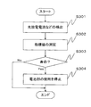
- FIG. 4 is a flowchart for explaining an example of the operation of the battery pack 100. In the battery pack 100, the following operation is periodically performed.
- the temperature sensor 23 detects the temperature of the battery unit 1 and notifies the monitoring IC 25 of a temperature signal indicating the temperature.
- the current detection unit 24 detects the charge / discharge current of the battery unit 1 and notifies the monitoring IC 25 of a current signal indicating the charge / discharge current.
- the monitoring IC 25 detects the cell voltage of each secondary battery cell 11 and receives a temperature signal and a current signal. Then, the monitoring IC 25 notifies the MCU 26 of the voltage signal indicating each detected cell voltage and the received temperature signal and current signal (step S301).
- the MCU 26 When receiving the voltage signal, the temperature signal, and the current signal, the MCU 26 measures a plurality of index values based on the voltage signal, the temperature signal, and the current signal (step S302).
- the MCU 26 uses a plurality of index values to determine whether or not the battery unit 1 has reached the end of life (step S303).
- the MCU 26 ends the process.
- the MCU 26 notifies the electric device that the battery unit 1 has reached the end of its life via the communication terminal CX and stops using the battery unit 1.
- a stop request is notified to the monitoring IC 25.
- the monitoring IC 25 turns off both the discharge FET 21 and the charge FET 22 to stop the use of the battery unit 1 (step S304), and ends the process.
- At least two or more of the capacity reduction rate, the number of cycles, the number of times of charging, the elapsed time, and the cell voltage of the battery unit 1 are measured as index values related to the deterioration state of the battery unit 1. Based on those index values, it is determined whether or not the battery unit has reached the end of its life. For this reason, it is possible to perform the determination of the deterioration state of the battery unit 1 with higher accuracy than the determination of the deterioration state due to the full charge capacity or the direct current resistance, and as a result, more accurately prevent adverse effects on the outside. Is possible.
- the predetermined charge amount decreases, so that it is possible to accurately determine the deterioration state of the battery unit 1.
- the number of times of charging the number of times charging of the battery unit 1 is started and the number of times the charging of the battery unit 1 has continued for a predetermined time or more is measured.
- count that the battery part 1 was charged to the full charge state is measured as the frequency
- the elapsed time is corrected based on the battery temperature, and it is determined whether or not the battery unit 1 has reached the end of its life using the corrected time that is the corrected elapsed time. It becomes possible to consider the deterioration of the battery unit 1 due to the temperature, and as a result, the deterioration state of the battery unit 1 can be accurately determined.
- the determination that the battery unit 1 has reached the end of its life using the capacity reduction rate is stopped, or the battery temperature is higher than the predetermined temperature.
- the reduction rate threshold value is small, it is possible to accurately determine the deterioration state of the battery unit 1.
- the charging rate of the battery unit 1 when the charging rate of the battery unit 1 is not included in the predetermined charging rate range, the determination of whether or not the battery unit 1 has reached the end of its life using the cell voltage, or Compared with the case where the charging rate is included in the predetermined charging rate range, the cell threshold value is increased, so that the deterioration state of the battery unit 1 can be accurately determined.
- a battery unit having a secondary battery cell As an index value related to the deterioration state of the battery unit, a capacity decrease rate that is a decrease rate from the initial value of the full charge capacity of the battery unit, until the cumulative value of the charge amount charged in the battery unit reaches a predetermined charge amount The number of cycles, which is the number of cycles that the battery unit is charged, the number of times the battery unit has been charged, the elapsed time since the battery unit was manufactured, and the voltage of the secondary battery cell A determination unit that measures at least two or more of a certain cell voltage and uses the measured index value to determine whether or not the battery unit has reached the end of its life; A battery pack comprising: a stop unit that stops use of the battery unit when the battery unit reaches the end of its life.
- Appendix 2 The battery pack according to appendix 1, wherein the determination unit measures at least the number of cycles and the elapsed time as the index value.
- Appendix 3 The battery pack according to appendix 1 or 2, wherein the determination unit measures the number of times the charging of the battery unit is started and the charging of the battery unit continues for a predetermined time or more as the number of times of charging.
- the said determination part is a battery pack of Additional remark 1 or 2 which measures the frequency
- Appendix 5 A temperature detection unit for detecting the temperature of the battery unit; When determining the elapsed time, the determination unit corrects the measured elapsed time based on the temperature, and uses the corrected time that is the corrected elapsed time to determine whether the battery unit has reached the end of its life.
- the battery pack according to any one of appendices 1 to 4, which determines whether or not.
- the determination unit determines, for each of the measured index values, whether the index value satisfies a life condition corresponding to the index value, and the battery unit reaches the life based on each determination result.
- the determination unit determines that the battery unit has reached the life when there are a predetermined number or more of index values that satisfy the life condition, The battery pack according to appendix 6, wherein the predetermined number is one.
- the life condition corresponding to the capacity reduction rate is that the capacity reduction rate is less than a predetermined reduction rate threshold,
- Appendix 9 A temperature detection unit for detecting the temperature of the battery unit; The battery pack according to appendix 8, wherein the determination unit stops determining whether the battery unit has reached the end of its life using the capacity decrease rate when the temperature is equal to or lower than a predetermined temperature.
- Appendix 10 A temperature detection unit for detecting the temperature of the battery unit; When the temperature is equal to or lower than the predetermined temperature, the determination unit lowers the decrease rate threshold as compared to a case where the temperature is higher than the predetermined temperature.
- Appendix 12 The battery pack according to any one of appendices 6 to 11, wherein the life condition corresponding to the number of times of charging is that the number of times of charging is equal to or greater than a predetermined number of times threshold.
- the determination unit measures the number of times the battery unit is charged to a fully charged state as the number of times of charging, The battery pack according to any one of appendices 6 to 11, wherein the frequency threshold is included in a range from 1000 times to 1200 times.
- the life condition corresponding to the elapsed time is that the elapsed time is equal to or greater than a predetermined time threshold, 14.
- the life condition corresponding to the cell voltage is that a deviation amount that is a difference between the maximum value and the minimum value of the cell voltages of the respective secondary battery cells is equal to or greater than a predetermined cell threshold value,
- the determination unit measures the charging rate of the battery unit, and when the charging rate is not included in a predetermined charging rate range, determines whether the battery unit has reached the end of its life using the cell voltage.
- Appendix 18 An electric device comprising the battery pack according to any one of appendices 1 to 17.
- Appendix 19 The electrical device according to appendix 18, wherein the electrical device is a moving body.
- a method for controlling a battery pack having a battery unit with secondary battery cells As an index value related to the deterioration state of the battery unit, a capacity decrease rate that is a decrease rate from the initial value of the full charge capacity of the battery unit, until the cumulative value of the charge amount charged in the battery unit reaches a predetermined charge amount
- the number of cycles that is the number of cycles that the battery unit is charged, the number of times that the battery unit is charged, the time that has elapsed since the battery unit is manufactured, and the distance between both electrodes of the secondary battery cell Measure at least two of the cell voltages that are Using the measured index value, determine whether the battery unit has reached the end of its life, A method for controlling a battery pack, wherein when the battery unit reaches the end of its life, the battery unit is suspended.
Abstract
Description
指標値として容量低下率を使用する場合、MCU26は、先ず、電流検出部24にて検出された放電電流と、温度センサ23にて検出された電池温度と、監視IC25にて検出された各2次電池セル11のセル電圧とに基づいて、電池部1の充電率が所定充電率になったか否かを判定する。 (1) Capacity reduction rate When the capacity reduction rate is used as an index value, the
指標値としてサイクル数を用いる場合、MCU26は、電流検出部24で検出された充放電流と、監視IC25にて検出された各2次電池セル11のセル電圧とに基づいて、電池部1のサイクル数を測定し、そのサイクル数が、サイクル数に対応する寿命条件であるサイクル数条件を満たすか否かを判定する。サイクル数条件は、例えば、サイクル数が予め定められたサイクル数閾値以上になることである。なお、サイクル数閾値は、例えば、700回から800回までの範囲に含まれる。 (2) Number of cycles When the number of cycles is used as the index value, the
(3)充電回数
指標値として充電回数を用いる場合、MCU26は、電流検出部24で検出された充放電流に基づいて、電池部1への充電が開始された回数を充電回数として測定し、その充電回数が、充電回数に対応する寿命条件である回数条件を満たすか否かを判定する。回数条件は、例えば、充電回数が予め定められた回数閾値以上になることである。 The number of cycles is the number of times that the accumulated value of the charged amount of the
(3) Number of times of charging When using the number of times of charging as an index value, the
(4)経過時間
指標値として経過時間を用いる場合、MCU26は、時間を測定する時計部(図示せず)を備え、その時計部を用いて経過時間を測定し、その経過時間が、経過時間に対応する寿命条件である時間条件を満たすか否かを判定する。時間条件は、例えば、経過時間が予め定められた時間閾値以上になることである。時間閾値は、例えば、3年から9年までの範囲に含まれる。 In the case where the number of times of charging is a fully charged state, if the charging / discharging is repeated, the number of times of charging is not counted up. It is desirable to use together.
(4) Elapsed time When the elapsed time is used as the index value, the
(5)セル電圧
複数の2次電池セル11が直列で接続されている場合、各2次電池セル11の劣化の度合いには個体差が存在するため、各2次電池セル11のセル電圧のずれ量が徐々に大きくなる。各セル電圧のずれ量が大きいほど、2次電池セル11の劣化が促進される。なお、各セル電圧のずれを抑制するためのセルバランス回路が電池パック100に組み込まれていても、セルバランス回路が動作しない条件で電池パック100が使用されることもある。例えば、セルバランス回路には、電池部1が満充電または満充電付近のときに、各セル電圧のずれを抑制するものがあり、この場合、充電率が低いと各セル電圧のずれを抑制することはできない。なお、電池部1の充電率が低いときにも各セル電圧のずれを抑制するようにセルバランス回路を構成することはできるが、この場合、電池部1が充電されると、劣化の度合いの大きい2次電池セルの電圧上昇が、劣化の度合いの小さい2次電池セルの電圧上昇よりも多くなってしまい、劣化の度合いの大きい2次電池セルの劣化を促進させてしまう。 When there are a plurality of
(5) Cell voltage When a plurality of
2次電池セルを備えた電池部と、
前記電池部の劣化状態に関する指標値として、前記電池部の満充電容量の初期値からの低下率である容量低下率、前記電池部に充電された充電量の累積値が所定充電量になるまで前記電池部が充電されるサイクルが行われた回数であるサイクル数、前記電池部が充電された充電回数、前記電池部が製造されてからの経過時間、および、前記2次電池セルの電圧であるセル電圧の少なくとも2以上を測定し、当該測定した指標値を使用して、前記電池部が寿命に到達したか否かを判定する判定部と、
前記電池部が寿命に到達した場合、前記電池部を使用停止にする停止部と、を有する電池パック。 [Appendix 1]
A battery unit having a secondary battery cell;
As an index value related to the deterioration state of the battery unit, a capacity decrease rate that is a decrease rate from the initial value of the full charge capacity of the battery unit, until the cumulative value of the charge amount charged in the battery unit reaches a predetermined charge amount The number of cycles, which is the number of cycles that the battery unit is charged, the number of times the battery unit has been charged, the elapsed time since the battery unit was manufactured, and the voltage of the secondary battery cell A determination unit that measures at least two or more of a certain cell voltage and uses the measured index value to determine whether or not the battery unit has reached the end of its life;
A battery pack comprising: a stop unit that stops use of the battery unit when the battery unit reaches the end of its life.
前記判定部は、前記指標値として、少なくとも前記サイクル数および前記経過時間を測定する、付記1に記載の電池パック。 [Appendix 2]
The battery pack according to
前記判定部は、前記充電回数として、前記電池部の充電が開始され、かつ、前記電池部の充電が所定時間以上継続した回数を測定する、付記1または2に記載の電池パック。 [Appendix 3]
The battery pack according to
前記判定部は、前記充電回数として、前記電池部が満充電状態まで充電された回数を測定する、付記1または2に記載の電池パック。 [Appendix 4]
The said determination part is a battery pack of
前記電池部の温度を検出する温度検出部をさらに備え、
前記判定部は、前記経過時間を測定する場合、前記測定した経過時間を前記温度に基づいて補正し、当該補正した経過時間である補正時間を使用して、前記電池部が寿命に到達したか否かを判定する、付記1ないし4のいずれか1項に記載の電池パック。 [Appendix 5]
A temperature detection unit for detecting the temperature of the battery unit;
When determining the elapsed time, the determination unit corrects the measured elapsed time based on the temperature, and uses the corrected time that is the corrected elapsed time to determine whether the battery unit has reached the end of its life. The battery pack according to any one of
前記判定部は、前記測定した指標値のそれぞれについて、当該指標値が、当該指標値に対応する寿命条件を満たすか否かを判断し、各判断結果に基づいて、前記電池部が寿命に到達したか否かを判定する、付記1ないし5に記載の電池パック。 [Appendix 6]
The determination unit determines, for each of the measured index values, whether the index value satisfies a life condition corresponding to the index value, and the battery unit reaches the life based on each determination result. The battery pack according to
前記判定部は、前記寿命条件を満たす指標値が所定数以上ある場合、前記電池部が寿命に到達したと判定し、
前記所定数は、1である、付記6に記載の電池パック。 [Appendix 7]
The determination unit determines that the battery unit has reached the life when there are a predetermined number or more of index values that satisfy the life condition,
The battery pack according to appendix 6, wherein the predetermined number is one.
前記容量低下率に対応する寿命条件は、前記容量低下率が予め定められた低下率閾値未満になることであり、
前記低下率閾値は、40%から60%までの範囲に含まれる、付記6または7記載の電池パック。 [Appendix 8]
The life condition corresponding to the capacity reduction rate is that the capacity reduction rate is less than a predetermined reduction rate threshold,
The battery pack according to appendix 6 or 7, wherein the reduction rate threshold is included in a range from 40% to 60%.
前記電池部の温度を検出する温度検出部をさらに有し、
前記判定部は、前記温度が所定温度以下の場合、前記容量低下率を使用した、前記電池部が寿命に到達したか否かの判定を停止する、付記8に記載の電池パック。 [Appendix 9]
A temperature detection unit for detecting the temperature of the battery unit;
The battery pack according to appendix 8, wherein the determination unit stops determining whether the battery unit has reached the end of its life using the capacity decrease rate when the temperature is equal to or lower than a predetermined temperature.
前記電池部の温度を検出する温度検出部をさらに有し、
前記判定部は、前記温度が所定温度以下の場合、前記温度が前記所定温度より高い場合に比べて、前記低下率閾値を下げ、
前記所定温度は、0℃から15℃までの範囲に含まれる、付記8に記載の電池パック。 [Appendix 10]
A temperature detection unit for detecting the temperature of the battery unit;
When the temperature is equal to or lower than the predetermined temperature, the determination unit lowers the decrease rate threshold as compared to a case where the temperature is higher than the predetermined temperature.
The battery pack according to appendix 8, wherein the predetermined temperature is included in a range from 0 ° C to 15 ° C.
前記サイクル数に対応する寿命条件は、前記サイクル数が予め定められたサイクル数閾値以上になることである、付記6ないし10のいずれか1項に記載の電池パック。 [Appendix 11]
The battery pack according to any one of appendices 6 to 10, wherein the life condition corresponding to the cycle number is that the cycle number is equal to or greater than a predetermined cycle number threshold value.
前記充電回数に対応する寿命条件は、前記充電回数が予め定められた回数閾値以上になることである、付記6ないし11のいずれか1項に記載の電池パック。 [Appendix 12]
The battery pack according to any one of appendices 6 to 11, wherein the life condition corresponding to the number of times of charging is that the number of times of charging is equal to or greater than a predetermined number of times threshold.
前記判定部は、前記充電回数として、前記電池部が満充電状態まで充電された回数を測定し、
前記回数閾値は、1000回から1200回までの範囲に含まれる、付記6ないし11のいずれか1項に記載の電池パック。 [Appendix 13]
The determination unit measures the number of times the battery unit is charged to a fully charged state as the number of times of charging,
The battery pack according to any one of appendices 6 to 11, wherein the frequency threshold is included in a range from 1000 times to 1200 times.
前記経過時間に対応する寿命条件は、前記経過時間が予め定められた時間閾値以上になることであり、
前記時間閾値は、3年から9年までの範囲に含まれる、付記6ないし13のいずれか1項に記載の電池パック。 [Appendix 14]
The life condition corresponding to the elapsed time is that the elapsed time is equal to or greater than a predetermined time threshold,
14. The battery pack according to any one of appendices 6 to 13, wherein the time threshold is included in a range from 3 to 9 years.
前記2次電池セルは複数あり、
前記セル電圧に対応する寿命条件は、各2次電池セルのセル電圧のうちの最大値と最小値との差であるずれ量が予め定められたセル閾値以上になることであり、
前記セル閾値は、100mVから200mVの範囲に含まれる、付記6ないし14のいずれか1項に記載の電池パック。 [Appendix 15]
There are a plurality of the secondary battery cells,
The life condition corresponding to the cell voltage is that a deviation amount that is a difference between the maximum value and the minimum value of the cell voltages of the respective secondary battery cells is equal to or greater than a predetermined cell threshold value,
The battery pack according to any one of appendices 6 to 14, wherein the cell threshold value is included in a range of 100 mV to 200 mV.
前記判定部は、前記電池部の充電率を測定し、当該充電率が所定充電率範囲に含まれない場合、前記セル電圧を使用した、前記電池部が寿命に到達したか否かの判定を停止する、付記15に記載の電池パック。 [Appendix 16]
The determination unit measures the charging rate of the battery unit, and when the charging rate is not included in a predetermined charging rate range, determines whether the battery unit has reached the end of its life using the cell voltage. The battery pack according to appendix 15, wherein the battery pack is stopped.
前記2次電池セルは、正極にマンガンを用いたマンガンスピネル系リチウムイオン2次電池セルである、付記1ないし16のいずれか1項に記載の電池パック。 [Appendix 17]
The battery pack according to any one of
付記1ないし17のいずれか1項に記載の電池パックを備えた電気機器。 [Appendix 18]
An electric device comprising the battery pack according to any one of
前記電気機器は、移動体である、付記18に記載の電気機器。 [Appendix 19]
The electrical device according to appendix 18, wherein the electrical device is a moving body.
2次電池セルを備えた電池部を有する電池パックの制御方法であって、
前記電池部の劣化状態に関する指標値として、前記電池部の満充電容量の初期値からの低下率である容量低下率、前記電池部に充電された充電量の累積値が所定充電量になるまで前記電池部が充電されるサイクルが行われた回数であるサイクル数、前記電池部が充電された充電回数、前記電池部が製造されてからの経過時間、および、前記2次電池セルの両極間の電圧であるセル電圧の少なくとも2以上を測定し、
当該測定した指標値を使用して、前記電池部が寿命に到達したか否かを判定し、
前記電池部が寿命に到達した場合、前記電池部を使用停止にする、電池パックの制御方法。 [Appendix 20]
A method for controlling a battery pack having a battery unit with secondary battery cells,
As an index value related to the deterioration state of the battery unit, a capacity decrease rate that is a decrease rate from the initial value of the full charge capacity of the battery unit, until the cumulative value of the charge amount charged in the battery unit reaches a predetermined charge amount The number of cycles that is the number of cycles that the battery unit is charged, the number of times that the battery unit is charged, the time that has elapsed since the battery unit is manufactured, and the distance between both electrodes of the secondary battery cell Measure at least two of the cell voltages that are
Using the measured index value, determine whether the battery unit has reached the end of its life,
A method for controlling a battery pack, wherein when the battery unit reaches the end of its life, the battery unit is suspended.
2 保護回路
11 2次電池セル
21 放電FET
22 充電FET
23 温度センサ
24 電流検出部
25 監視IC
26 MCU
100 電池パック
200 電気機器
201 負荷
202 制御部
203 通知部 DESCRIPTION OF
22 Charge FET
23
26 MCU
DESCRIPTION OF
Claims (10)
- 2次電池セルを備えた電池部と、
前記電池部の劣化状態に関する指標値として、前記電池部の満充電容量の初期値からの低下率である容量低下率、前記電池部に充電された充電量の累積値が所定充電量になるまで前記電池部が充電されるサイクルが行われた回数であるサイクル数、前記電池部が充電された充電回数、前記電池部が製造されてからの経過時間、および、前記2次電池セルの電圧であるセル電圧の少なくとも2以上を測定し、当該測定した指標値を使用して、前記電池部が寿命に到達したか否かを判定する判定部と、
前記電池部が寿命に到達した場合、前記電池部を使用停止にする停止部と、を有する電池パック。 A battery unit having a secondary battery cell;
As an index value related to the deterioration state of the battery unit, a capacity decrease rate that is a decrease rate from the initial value of the full charge capacity of the battery unit, until the cumulative value of the charge amount charged in the battery unit reaches a predetermined charge amount The number of cycles, which is the number of cycles that the battery unit is charged, the number of times the battery unit has been charged, the elapsed time since the battery unit was manufactured, and the voltage of the secondary battery cell A determination unit that measures at least two or more of a certain cell voltage and uses the measured index value to determine whether or not the battery unit has reached the end of its life;
A battery pack comprising: a stop unit that stops use of the battery unit when the battery unit reaches the end of its life. - 前記判定部は、前記指標値として、少なくとも前記サイクル数および前記経過時間を測定する、請求項1に記載の電池パック。 The battery pack according to claim 1, wherein the determination unit measures at least the number of cycles and the elapsed time as the index value.
- 前記判定部は、前記充電回数として、前記電池部の充電が開始され、かつ、前記電池部の充電が所定時間以上継続した回数を測定する、請求項1または2に記載の電池パック。 3. The battery pack according to claim 1, wherein the determination unit measures the number of times that charging of the battery unit is started and charging of the battery unit continues for a predetermined time or more as the number of times of charging.
- 前記判定部は、前記充電回数として、前記電池部が満充電状態まで充電された回数を測定する、請求項1または2に記載の電池パック。 The battery pack according to claim 1 or 2, wherein the determination unit measures the number of times the battery unit has been charged to a fully charged state as the number of times of charging.
- 前記電池部の温度を検出する温度検出部をさらに備え、
前記判定部は、前記経過時間を測定する場合、前記測定した経過時間を前記温度に基づいて補正し、当該補正した経過時間である補正時間を使用して、前記電池部が寿命に到達したか否かを判定する、請求項1ないし4のいずれか1項に記載の電池パック。 A temperature detection unit for detecting the temperature of the battery unit;
When determining the elapsed time, the determination unit corrects the measured elapsed time based on the temperature, and uses the corrected time that is the corrected elapsed time to determine whether the battery unit has reached the end of its life. The battery pack according to any one of claims 1 to 4, wherein a determination is made as to whether or not. - 前記判定部は、前記測定した指標値のそれぞれについて、当該指標値が、当該指標値に対応する寿命条件を満たすか否かを判断し、各判断結果に基づいて、前記電池部が寿命に到達したか否かを判定する、請求項1ないし5に記載の電池パック。 The determination unit determines, for each of the measured index values, whether the index value satisfies a life condition corresponding to the index value, and the battery unit reaches the life based on each determination result. The battery pack according to claim 1, wherein it is determined whether or not the battery pack has been used.
- 前記判定部は、前記寿命条件を満たす指標値が所定数以上ある場合、前記電池部が寿命に到達したと判定し、
前記所定数は、1である、請求項6に記載の電池パック。 The determination unit determines that the battery unit has reached the life when there are a predetermined number or more of index values that satisfy the life condition,
The battery pack according to claim 6, wherein the predetermined number is one. - 前記容量低下率に対応する寿命条件は、前記容量低下率が予め定められた低下率閾値未満になることであり、
前記低下率閾値は、40%から60%までの範囲に含まれる、請求項6または7記載の電池パック。 The life condition corresponding to the capacity reduction rate is that the capacity reduction rate is less than a predetermined reduction rate threshold,
The battery pack according to claim 6 or 7, wherein the reduction rate threshold value is included in a range of 40% to 60%. - 請求項1ないし8のいずれか1項に記載の電池パックを備えた電気機器。 An electric device comprising the battery pack according to any one of claims 1 to 8.
- 2次電池セルを備えた電池部を有する電池パックの制御方法であって、
前記電池部の劣化状態に関する指標値として、前記電池部の満充電容量の初期値からの低下率である容量低下率、前記電池部に充電された充電量の累積値が所定充電量になるまで前記電池部が充電されるサイクルが行われた回数であるサイクル数、前記電池部が充電された充電回数、前記電池部が製造されてからの経過時間、および、前記2次電池セルの両極間の電圧であるセル電圧の少なくとも2以上を測定し、
当該測定した指標値を使用して、前記電池部が寿命に到達したか否かを判定し、
前記電池部が寿命に到達した場合、前記電池部を使用停止にする、電池パックの制御方法。 A method for controlling a battery pack having a battery unit with secondary battery cells,
As an index value related to the deterioration state of the battery unit, a capacity decrease rate that is a decrease rate from the initial value of the full charge capacity of the battery unit, until the cumulative value of the charge amount charged in the battery unit reaches a predetermined charge amount The number of cycles that is the number of cycles that the battery unit is charged, the number of times that the battery unit is charged, the time that has elapsed since the battery unit is manufactured, and the distance between both electrodes of the secondary battery cell Measure at least two of the cell voltages that are
Using the measured index value, determine whether the battery unit has reached the end of its life,
A method for controlling a battery pack, wherein when the battery unit reaches the end of its life, the battery unit is suspended.
Priority Applications (2)
| Application Number | Priority Date | Filing Date | Title |
|---|---|---|---|
| US14/775,194 US10218036B2 (en) | 2013-03-13 | 2014-02-19 | Battery pack, electrical device, and control method therefor |
| JP2015505345A JPWO2014141834A1 (en) | 2013-03-13 | 2014-02-19 | Battery pack, electric device and control method thereof |
Applications Claiming Priority (2)
| Application Number | Priority Date | Filing Date | Title |
|---|---|---|---|
| JP2013050085 | 2013-03-13 | ||
| JP2013-050085 | 2013-03-13 |
Publications (1)
| Publication Number | Publication Date |
|---|---|
| WO2014141834A1 true WO2014141834A1 (en) | 2014-09-18 |
Family
ID=51536509
Family Applications (1)
| Application Number | Title | Priority Date | Filing Date |
|---|---|---|---|
| PCT/JP2014/053866 WO2014141834A1 (en) | 2013-03-13 | 2014-02-19 | Battery pack, electrical device, and control method therefor |
Country Status (3)
| Country | Link |
|---|---|
| US (1) | US10218036B2 (en) |
| JP (1) | JPWO2014141834A1 (en) |
| WO (1) | WO2014141834A1 (en) |
Cited By (6)
| Publication number | Priority date | Publication date | Assignee | Title |
|---|---|---|---|---|
| JP2016070920A (en) * | 2014-09-30 | 2016-05-09 | 株式会社Gsユアサ | Battery deterioration determination device, battery deterioration determination method, and vehicle |
| JP2017129400A (en) * | 2016-01-19 | 2017-07-27 | 日立化成株式会社 | Battery state estimation device |
| CN107615613A (en) * | 2015-11-18 | 2018-01-19 | 株式会社Lg化学 | Management device of battery pack and method |
| JP2018119828A (en) * | 2017-01-24 | 2018-08-02 | 株式会社豊田自動織機 | Battery pack |
| WO2019077712A1 (en) | 2017-10-18 | 2019-04-25 | 日本たばこ産業株式会社 | Battery unit, flavor inhaler, method for controlling battery unit, and program |
| WO2019077711A1 (en) | 2017-10-18 | 2019-04-25 | 日本たばこ産業株式会社 | Battery unit, flavor inhaler, method for controlling battery unit, and program |
Families Citing this family (5)
| Publication number | Priority date | Publication date | Assignee | Title |
|---|---|---|---|---|
| KR102035679B1 (en) * | 2016-11-29 | 2019-10-23 | 주식회사 엘지화학 | Method and system for caculating state of health(soh) of a battery |
| DE102017208770B4 (en) * | 2017-05-23 | 2019-03-28 | Audi Ag | Method for checking a battery condition and tester for checking a battery condition |
| WO2019037108A1 (en) * | 2017-08-25 | 2019-02-28 | 深圳市云中飞网络科技有限公司 | Terminal device, adapter, battery safety monitoring method and monitoring system |
| WO2020137815A1 (en) * | 2018-12-25 | 2020-07-02 | 三洋電機株式会社 | Standby power supply device and method for charging secondary battery |
| JP7452273B2 (en) * | 2020-06-12 | 2024-03-19 | トヨタ自動車株式会社 | battery system |
Citations (5)
| Publication number | Priority date | Publication date | Assignee | Title |
|---|---|---|---|---|
| JPH07130402A (en) * | 1993-11-01 | 1995-05-19 | Stanley Electric Co Ltd | Battery capacity meter |
| JPH09269360A (en) * | 1996-03-29 | 1997-10-14 | Shindengen Electric Mfg Co Ltd | Uninterruptible power supply apparatus |
| JPH09293539A (en) * | 1996-02-28 | 1997-11-11 | Shin Kobe Electric Mach Co Ltd | Storage battery deterioration diagnostic method its device and ac uninterruptive power supply |
| JP2008277136A (en) * | 2007-04-27 | 2008-11-13 | Matsushita Electric Ind Co Ltd | Battery pack, battery circuit, and charging system |
| JP2011053097A (en) * | 2009-09-02 | 2011-03-17 | Panasonic Corp | Discharge management circuit and battery pack |
Family Cites Families (14)
| Publication number | Priority date | Publication date | Assignee | Title |
|---|---|---|---|---|
| WO2009069201A1 (en) * | 2007-11-28 | 2009-06-04 | Olympus Medical Systems Corp. | Battery management system and charger |
| US20130033102A1 (en) * | 2008-02-20 | 2013-02-07 | Lonnie Calvin Goff | Embedded battery management system and methods |
| JP2010166752A (en) | 2009-01-19 | 2010-07-29 | Sony Corp | Battery pack and method of controlling charging and discharging |
| US8415926B2 (en) * | 2009-10-19 | 2013-04-09 | Apple Inc. | In-situ battery health detector and end-of-life indicator |
| JP2012168728A (en) | 2011-02-14 | 2012-09-06 | Mitsumi Electric Co Ltd | Protection module and state information management method in protection module |
| US9531037B2 (en) * | 2011-08-23 | 2016-12-27 | Servato Corp. | Battery management |
| WO2013094344A1 (en) * | 2011-12-22 | 2013-06-27 | 日本電気株式会社 | Storage battery device and charging control method |
| CN104203633B (en) * | 2012-03-19 | 2017-03-29 | 日产自动车株式会社 | Battery temperature adjusting means |
| US9442165B2 (en) * | 2012-07-07 | 2016-09-13 | Nec Corporation | Method for estimating battery life in presence of partial charge and discharge cycles |
| US9472959B2 (en) * | 2012-11-30 | 2016-10-18 | GM Global Technology Operations LLC | Systems and methods for balancing a vehicle battery system |
| DE102012222746A1 (en) * | 2012-12-11 | 2014-06-12 | Robert Bosch Gmbh | Battery module balancing and battery management system |
| US10870360B2 (en) * | 2013-02-12 | 2020-12-22 | Cps Technology Holdings Llc | Battery monitoring network |
| US9276298B2 (en) * | 2013-02-28 | 2016-03-01 | NDSL, Inc. | Automatically determining alarm threshold settings for monitored battery system components in battery systems, and related components, systems, and methods |
| WO2015092846A1 (en) * | 2013-12-16 | 2015-06-25 | 株式会社日立製作所 | Battery system and battery cell management device |
-
2014
- 2014-02-19 US US14/775,194 patent/US10218036B2/en active Active
- 2014-02-19 WO PCT/JP2014/053866 patent/WO2014141834A1/en active Application Filing
- 2014-02-19 JP JP2015505345A patent/JPWO2014141834A1/en active Pending
Patent Citations (5)
| Publication number | Priority date | Publication date | Assignee | Title |
|---|---|---|---|---|
| JPH07130402A (en) * | 1993-11-01 | 1995-05-19 | Stanley Electric Co Ltd | Battery capacity meter |
| JPH09293539A (en) * | 1996-02-28 | 1997-11-11 | Shin Kobe Electric Mach Co Ltd | Storage battery deterioration diagnostic method its device and ac uninterruptive power supply |
| JPH09269360A (en) * | 1996-03-29 | 1997-10-14 | Shindengen Electric Mfg Co Ltd | Uninterruptible power supply apparatus |
| JP2008277136A (en) * | 2007-04-27 | 2008-11-13 | Matsushita Electric Ind Co Ltd | Battery pack, battery circuit, and charging system |
| JP2011053097A (en) * | 2009-09-02 | 2011-03-17 | Panasonic Corp | Discharge management circuit and battery pack |
Cited By (9)
| Publication number | Priority date | Publication date | Assignee | Title |
|---|---|---|---|---|
| JP2016070920A (en) * | 2014-09-30 | 2016-05-09 | 株式会社Gsユアサ | Battery deterioration determination device, battery deterioration determination method, and vehicle |
| CN107615613A (en) * | 2015-11-18 | 2018-01-19 | 株式会社Lg化学 | Management device of battery pack and method |
| EP3280024A4 (en) * | 2015-11-18 | 2018-12-19 | LG Chem, Ltd. | Battery pack management apparatus and method |
| CN107615613B (en) * | 2015-11-18 | 2020-09-29 | 株式会社Lg化学 | Battery pack management apparatus and method |
| JP2017129400A (en) * | 2016-01-19 | 2017-07-27 | 日立化成株式会社 | Battery state estimation device |
| JP2018119828A (en) * | 2017-01-24 | 2018-08-02 | 株式会社豊田自動織機 | Battery pack |
| WO2019077712A1 (en) | 2017-10-18 | 2019-04-25 | 日本たばこ産業株式会社 | Battery unit, flavor inhaler, method for controlling battery unit, and program |
| WO2019077711A1 (en) | 2017-10-18 | 2019-04-25 | 日本たばこ産業株式会社 | Battery unit, flavor inhaler, method for controlling battery unit, and program |
| US11705744B2 (en) | 2017-10-18 | 2023-07-18 | Japan Tobacco Inc. | Battery unit, flavor inhaler, method for controlling battery unit, and program for detecting degradation of a chargeable and dischargeable power supply of a battery unit of a vaporizor |
Also Published As
| Publication number | Publication date |
|---|---|
| US20160036096A1 (en) | 2016-02-04 |
| JPWO2014141834A1 (en) | 2017-02-16 |
| US10218036B2 (en) | 2019-02-26 |
Similar Documents
| Publication | Publication Date | Title |
|---|---|---|
| WO2014141834A1 (en) | Battery pack, electrical device, and control method therefor | |
| JP5289083B2 (en) | Secondary battery abnormality detection device and secondary battery device | |
| US8749204B2 (en) | Battery condition detector, battery pack including same, and battery condition detecting method | |
| US9172261B2 (en) | Battery pack, method of charging secondary battery and battery charger | |
| KR101016899B1 (en) | Battery pack and method of charge thereof | |
| JP4692554B2 (en) | Charger | |
| US8421466B2 (en) | Apparatus and method for sensing leakage current of battery | |
| US8996324B2 (en) | Battery-state monitoring apparatus | |
| KR101387733B1 (en) | Battery pack, battery pack arrangement and electric apparatus | |
| US20110112782A1 (en) | Battery status detection device | |
| US20090184685A1 (en) | Battery pack and method of charging the same | |
| JP2008253129A (en) | Method for quick charging lithium-based secondary battery and electronic equipment using same | |
| US20130148246A1 (en) | Protection circuit of battery pack and battery pack using the same | |
| WO2011048471A1 (en) | Power supply apparatus | |
| US9863993B2 (en) | Storage battery monitoring device with wiring disconnection detection | |
| CN105203958A (en) | Battery state monitoring circuit and battery device | |
| KR102073190B1 (en) | Battery pack and controlling method of the same | |
| US11114703B2 (en) | Battery pack | |
| JP5474438B2 (en) | Secondary battery device | |
| KR102196270B1 (en) | Method and apparatus for detecting short of a battery cell | |
| JP2005108491A (en) | Electronic apparatus | |
| KR102497448B1 (en) | Apparatus and method for determining error of a battery cell | |
| JP2004014462A (en) | Remaining capacity measurement device of secondary battery | |
| KR20210087294A (en) | Apparatus and method for managing battery | |
| JP7113976B2 (en) | Charge/discharge control device and charge/discharge control method |
Legal Events
| Date | Code | Title | Description |
|---|---|---|---|
| 121 | Ep: the epo has been informed by wipo that ep was designated in this application |
Ref document number: 14764666 Country of ref document: EP Kind code of ref document: A1 |
|
| ENP | Entry into the national phase |
Ref document number: 2015505345 Country of ref document: JP Kind code of ref document: A |
|
| WWE | Wipo information: entry into national phase |
Ref document number: 14775194 Country of ref document: US |
|
| NENP | Non-entry into the national phase |
Ref country code: DE |
|
| 122 | Ep: pct application non-entry in european phase |
Ref document number: 14764666 Country of ref document: EP Kind code of ref document: A1 |