WO2014141647A1 - Information processing device, information processing method, and information processing program - Google Patents
Information processing device, information processing method, and information processing program Download PDFInfo
- Publication number
- WO2014141647A1 WO2014141647A1 PCT/JP2014/001258 JP2014001258W WO2014141647A1 WO 2014141647 A1 WO2014141647 A1 WO 2014141647A1 JP 2014001258 W JP2014001258 W JP 2014001258W WO 2014141647 A1 WO2014141647 A1 WO 2014141647A1
- Authority
- WO
- WIPO (PCT)
- Prior art keywords
- focus position
- feature amount
- image
- unit
- information processing
- Prior art date
Links
- 230000010365 information processing Effects 0.000 title claims abstract description 61
- 238000003672 processing method Methods 0.000 title description 3
- 238000004364 calculation method Methods 0.000 claims abstract description 154
- 238000000034 method Methods 0.000 claims description 189
- 238000012545 processing Methods 0.000 claims description 78
- 238000001514 detection method Methods 0.000 claims description 32
- 241001156002 Anthonomus pomorum Species 0.000 claims description 12
- 239000011521 glass Substances 0.000 claims description 7
- 230000002093 peripheral effect Effects 0.000 claims description 7
- 238000003384 imaging method Methods 0.000 description 82
- 230000008569 process Effects 0.000 description 71
- 239000000523 sample Substances 0.000 description 68
- 238000002360 preparation method Methods 0.000 description 36
- 230000003287 optical effect Effects 0.000 description 18
- 238000010586 diagram Methods 0.000 description 16
- 238000005516 engineering process Methods 0.000 description 16
- 238000005286 illumination Methods 0.000 description 14
- 230000007246 mechanism Effects 0.000 description 14
- 238000010186 staining Methods 0.000 description 12
- 238000007796 conventional method Methods 0.000 description 11
- 238000011161 development Methods 0.000 description 9
- 238000003860 storage Methods 0.000 description 9
- WZUVPPKBWHMQCE-UHFFFAOYSA-N Haematoxylin Chemical compound C12=CC(O)=C(O)C=C2CC2(O)C1C1=CC=C(O)C(O)=C1OC2 WZUVPPKBWHMQCE-UHFFFAOYSA-N 0.000 description 8
- 239000012472 biological sample Substances 0.000 description 8
- 230000008859 change Effects 0.000 description 8
- 238000012795 verification Methods 0.000 description 8
- 238000012790 confirmation Methods 0.000 description 7
- 230000006870 function Effects 0.000 description 7
- 210000001519 tissue Anatomy 0.000 description 7
- 240000004050 Pentaglottis sempervirens Species 0.000 description 5
- 235000004522 Pentaglottis sempervirens Nutrition 0.000 description 5
- 230000006835 compression Effects 0.000 description 4
- 238000007906 compression Methods 0.000 description 4
- 238000004043 dyeing Methods 0.000 description 4
- YQGOJNYOYNNSMM-UHFFFAOYSA-N eosin Chemical compound [Na+].OC(=O)C1=CC=CC=C1C1=C2C=C(Br)C(=O)C(Br)=C2OC2=C(Br)C(O)=C(Br)C=C21 YQGOJNYOYNNSMM-UHFFFAOYSA-N 0.000 description 4
- 210000000577 adipose tissue Anatomy 0.000 description 2
- 230000001413 cellular effect Effects 0.000 description 2
- 239000000428 dust Substances 0.000 description 2
- 239000000284 extract Substances 0.000 description 2
- 230000010354 integration Effects 0.000 description 2
- 238000005192 partition Methods 0.000 description 2
- 238000012887 quadratic function Methods 0.000 description 2
- 102000004190 Enzymes Human genes 0.000 description 1
- 108090000790 Enzymes Proteins 0.000 description 1
- 238000002738 Giemsa staining Methods 0.000 description 1
- 238000003794 Gram staining Methods 0.000 description 1
- 210000004369 blood Anatomy 0.000 description 1
- 239000008280 blood Substances 0.000 description 1
- 238000006243 chemical reaction Methods 0.000 description 1
- 238000004891 communication Methods 0.000 description 1
- 210000002808 connective tissue Anatomy 0.000 description 1
- 238000009826 distribution Methods 0.000 description 1
- 238000003708 edge detection Methods 0.000 description 1
- 230000000694 effects Effects 0.000 description 1
- 210000000981 epithelium Anatomy 0.000 description 1
- 239000007850 fluorescent dye Substances 0.000 description 1
- 238000007901 in situ hybridization Methods 0.000 description 1
- 230000001788 irregular Effects 0.000 description 1
- 238000005304 joining Methods 0.000 description 1
- 238000005259 measurement Methods 0.000 description 1
- 238000001000 micrograph Methods 0.000 description 1
- 238000010827 pathological analysis Methods 0.000 description 1
- 230000004044 response Effects 0.000 description 1
- 238000004904 shortening Methods 0.000 description 1
Images


Classifications
-
- G—PHYSICS
- G02—OPTICS
- G02B—OPTICAL ELEMENTS, SYSTEMS OR APPARATUS
- G02B21/00—Microscopes
- G02B21/36—Microscopes arranged for photographic purposes or projection purposes or digital imaging or video purposes including associated control and data processing arrangements
- G02B21/365—Control or image processing arrangements for digital or video microscopes
- G02B21/367—Control or image processing arrangements for digital or video microscopes providing an output produced by processing a plurality of individual source images, e.g. image tiling, montage, composite images, depth sectioning, image comparison
-
- G—PHYSICS
- G01—MEASURING; TESTING
- G01J—MEASUREMENT OF INTENSITY, VELOCITY, SPECTRAL CONTENT, POLARISATION, PHASE OR PULSE CHARACTERISTICS OF INFRARED, VISIBLE OR ULTRAVIOLET LIGHT; COLORIMETRY; RADIATION PYROMETRY
- G01J3/00—Spectrometry; Spectrophotometry; Monochromators; Measuring colours
- G01J3/46—Measurement of colour; Colour measuring devices, e.g. colorimeters
- G01J3/463—Colour matching
-
- G—PHYSICS
- G02—OPTICS
- G02B—OPTICAL ELEMENTS, SYSTEMS OR APPARATUS
- G02B21/00—Microscopes
- G02B21/0004—Microscopes specially adapted for specific applications
- G02B21/0016—Technical microscopes, e.g. for inspection or measuring in industrial production processes
-
- G—PHYSICS
- G02—OPTICS
- G02B—OPTICAL ELEMENTS, SYSTEMS OR APPARATUS
- G02B21/00—Microscopes
- G02B21/06—Means for illuminating specimens
- G02B21/08—Condensers
- G02B21/14—Condensers affording illumination for phase-contrast observation
-
- G—PHYSICS
- G02—OPTICS
- G02B—OPTICAL ELEMENTS, SYSTEMS OR APPARATUS
- G02B21/00—Microscopes
- G02B21/18—Arrangements with more than one light path, e.g. for comparing two specimens
-
- G—PHYSICS
- G02—OPTICS
- G02B—OPTICAL ELEMENTS, SYSTEMS OR APPARATUS
- G02B21/00—Microscopes
- G02B21/24—Base structure
- G02B21/241—Devices for focusing
- G02B21/244—Devices for focusing using image analysis techniques
-
- G—PHYSICS
- G02—OPTICS
- G02B—OPTICAL ELEMENTS, SYSTEMS OR APPARATUS
- G02B21/00—Microscopes
- G02B21/24—Base structure
- G02B21/241—Devices for focusing
- G02B21/245—Devices for focusing using auxiliary sources, detectors
-
- G—PHYSICS
- G02—OPTICS
- G02B—OPTICAL ELEMENTS, SYSTEMS OR APPARATUS
- G02B7/00—Mountings, adjusting means, or light-tight connections, for optical elements
- G02B7/28—Systems for automatic generation of focusing signals
- G02B7/34—Systems for automatic generation of focusing signals using different areas in a pupil plane
-
- G—PHYSICS
- G02—OPTICS
- G02B—OPTICAL ELEMENTS, SYSTEMS OR APPARATUS
- G02B7/00—Mountings, adjusting means, or light-tight connections, for optical elements
- G02B7/28—Systems for automatic generation of focusing signals
- G02B7/36—Systems for automatic generation of focusing signals using image sharpness techniques, e.g. image processing techniques for generating autofocus signals
-
- G—PHYSICS
- G03—PHOTOGRAPHY; CINEMATOGRAPHY; ANALOGOUS TECHNIQUES USING WAVES OTHER THAN OPTICAL WAVES; ELECTROGRAPHY; HOLOGRAPHY
- G03B—APPARATUS OR ARRANGEMENTS FOR TAKING PHOTOGRAPHS OR FOR PROJECTING OR VIEWING THEM; APPARATUS OR ARRANGEMENTS EMPLOYING ANALOGOUS TECHNIQUES USING WAVES OTHER THAN OPTICAL WAVES; ACCESSORIES THEREFOR
- G03B13/00—Viewfinders; Focusing aids for cameras; Means for focusing for cameras; Autofocus systems for cameras
- G03B13/32—Means for focusing
- G03B13/34—Power focusing
- G03B13/36—Autofocus systems
-
- G—PHYSICS
- G06—COMPUTING; CALCULATING OR COUNTING
- G06T—IMAGE DATA PROCESSING OR GENERATION, IN GENERAL
- G06T3/00—Geometric image transformation in the plane of the image
- G06T3/40—Scaling the whole image or part thereof
-
- H—ELECTRICITY
- H04—ELECTRIC COMMUNICATION TECHNIQUE
- H04N—PICTORIAL COMMUNICATION, e.g. TELEVISION
- H04N23/00—Cameras or camera modules comprising electronic image sensors; Control thereof
- H04N23/60—Control of cameras or camera modules
- H04N23/67—Focus control based on electronic image sensor signals
- H04N23/672—Focus control based on electronic image sensor signals based on the phase difference signals
-
- H—ELECTRICITY
- H04—ELECTRIC COMMUNICATION TECHNIQUE
- H04N—PICTORIAL COMMUNICATION, e.g. TELEVISION
- H04N23/00—Cameras or camera modules comprising electronic image sensors; Control thereof
- H04N23/60—Control of cameras or camera modules
- H04N23/67—Focus control based on electronic image sensor signals
- H04N23/673—Focus control based on electronic image sensor signals based on contrast or high frequency components of image signals, e.g. hill climbing method
-
- H—ELECTRICITY
- H04—ELECTRIC COMMUNICATION TECHNIQUE
- H04N—PICTORIAL COMMUNICATION, e.g. TELEVISION
- H04N23/00—Cameras or camera modules comprising electronic image sensors; Control thereof
- H04N23/70—Circuitry for compensating brightness variation in the scene
- H04N23/74—Circuitry for compensating brightness variation in the scene by influencing the scene brightness using illuminating means
-
- G—PHYSICS
- G01—MEASURING; TESTING
- G01J—MEASUREMENT OF INTENSITY, VELOCITY, SPECTRAL CONTENT, POLARISATION, PHASE OR PULSE CHARACTERISTICS OF INFRARED, VISIBLE OR ULTRAVIOLET LIGHT; COLORIMETRY; RADIATION PYROMETRY
- G01J3/00—Spectrometry; Spectrophotometry; Monochromators; Measuring colours
- G01J3/46—Measurement of colour; Colour measuring devices, e.g. colorimeters
- G01J2003/467—Colour computing
Definitions
- This technology relates to a digital microscope apparatus that captures an image of a preparation on which a specimen is placed to acquire an image.
- an enlarged optical system is used to enlarge a cell tissue slide, project it onto an image sensor, take an image, and stitch (synthesize) multiple images to form one huge specimen image. To do.
- Some digital microscope apparatuses employ a contrast autofocus (hereinafter abbreviated as AF) system and a phase difference AF system in order to automatically perform focus alignment.
- AF contrast autofocus
- phase difference AF phase difference AF
- the AF method shown in Patent Document 1 when searching for a point where the contrast becomes maximum, the difference between the previous contrast value and the current contrast value is used, and the magnitude of the difference is used as a threshold value.
- the focus position is specified using the threshold value.
- hue information is included in the definition of the feature quantity indicating contrast.
- the amount of a high frequency component is adopted as the definition of the feature amount indicating contrast.
- an imaging method is used in which the focal position is searched in advance at the selected representative point, and the focal position of each point in the imaging area is estimated from the result.
- the contrast AF method is said to have high accuracy, but it takes a considerable amount of time to repeat the search shooting and the confirmation of the contrast one after another as described above. Therefore, the search shooting is minimized and curve fitting is used.
- a method for estimating the in-focus position is known.
- curve fitting can be performed as a simple quadratic function by using the reciprocal thereof.
- the phase difference AF method when adopted, the focusing speed is fast, but depending on the type of staining of the specimen sample, the difference in image characteristics may not be captured by the low resolution image sensor for phase difference AF. In this case, there is a problem that the in-focus position cannot be obtained correctly.
- the in-focus position calculated by the two AF methods is compared (specifically, by checking whether the difference value is smaller than a predetermined threshold value), the accuracy of the in-focus position is obtained. There is also a way to go. However, good results are not always obtained even if low precision ones are compared. When shooting an object that is not good with both methods, there is a high possibility that it is determined that the subject is in focus even though the subject is not in focus.
- an overhead image is first captured, and the region where the specimen sample exists is detected in advance using the overhead image, There is also a method in which only a certain area is photographed.
- an object of the present technology is to provide an information processing apparatus, an information processing method, and an information processing program for obtaining an appropriate in-focus position at a high speed and performing shooting efficiently.
- an information processing apparatus includes a search image acquisition unit that acquires enlarged images at different focal positions, and the enlarged images for each of the plurality of captured enlarged images.
- a first feature amount calculation unit for obtaining a first feature amount based on a dynamic range of a DC component and an AC component of a pixel value for each block constituting the image; and a combination of the enlarged image based on the first feature amount.
- An in-focus position determining unit that determines the in-focus position.
- the pixel value in the adjacent block of the same color pixel (for example, a sequence of 8 pixels of the same color).
- the AC component and the DC component are obtained.
- the dynamic range and the direct current component of the alternating current component are filtered by a threshold value, a predetermined unit feature amount is obtained only for the block having the dynamic range and the direct current component corresponding to the condition, and the unit feature amount is obtained as one image.
- the in-focus position when the image is taken is obtained based on the first feature amount based on the sum of the values. Therefore, the in-focus position can be obtained with high accuracy.
- the first feature quantity calculation unit is configured such that the first feature quantity calculation unit satisfies a first condition in which a dynamic range of the AC component satisfies a predetermined condition, and a second component in which the DC component is determined in advance.
- a configuration may be used in which the first feature amount is obtained according to the block that satisfies the condition.
- the first feature amount calculation unit calculates and adds unit feature amounts by a predetermined method for the blocks satisfying the first condition and the second condition, and based on the sum result,
- requires the 1st feature-value for every enlarged image may be sufficient.
- a curve fitting unit that performs curve fitting from a combination of reciprocals of the first feature values at three or more focal positions to a predetermined curve, and calculates a focal position at which the reciprocal is minimum on the predetermined curve; Further, the focus position determination unit may be configured such that the focus position calculated by the curve fitting unit is a focus position.
- the predetermined curve may be a quadratic curve.
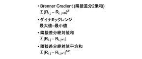
- the first feature amount calculation unit may calculate the first feature amount based on a minimum value of pixel values for each block and a difference value between the maximum value and the minimum value.
- the first feature amount calculation unit may use the dynamic range as the unit feature amount.
- the search image acquisition unit acquires a coarse search enlarged image at three or more focal positions separated by a first interval for roughly searching for a focus position, and the first feature amount calculation unit
- the first feature amount for each of the coarse search enlarged images is obtained
- the in-focus position determining unit obtains the in-focus position of the coarse search
- the in-search image acquiring unit is in the in-focus position of the coarse search.
- an enlarged image for fine search is acquired at three or more focal positions separated by a second interval narrower than the first interval for finely searching for a focus position.
- the feature amount calculation unit obtains the first feature amount for each of the enlarged images for fine search
- the focus position determination unit obtains the focus position of the fine search, and finally determines the focus position of the fine search. It is also possible to adopt a configuration in which the in-focus position is set.
- the search image acquisition unit acquires enlarged images at three or more different focal positions, and the first feature amount calculation unit calculates m ⁇ n (m, n Is divided into first integers of 2 or more) to determine the first feature amount for each first area, and the focus position determination unit determines a focus position for each first area.
- the configuration may be such that the tilt of the specimen is obtained from the focus position for each area, and the final focus position is selected based on the tilt.
- the first feature amount calculation unit obtains Brenner ⁇ Gradient of the enlarged image and adds the first feature amount in addition to the summation result.
- the structure to do may be sufficient.
- the phase difference AF detection unit for detecting the focus position by the phase difference AF (autofocus) method further includes a phase difference AF processing unit for detecting the phase difference focus position, and the search image acquisition unit A configuration may be used in which enlarged images are acquired at three or more different focal positions including a phase difference in-focus position therebetween.
- the in-focus position determination unit has a predetermined relationship in which the first feature amount at the phase difference in-focus position is maximum, and a reciprocal of the first feature amount at the focus position is predetermined.
- the phase difference in-focus position may be the final in-focus position.
- a phase difference AF detection unit that detects a focus position by a phase difference AF (autofocus) method, a phase difference AF processing unit that detects the phase difference focus position, and a plurality of sections that divide a region including the specimen on the slide glass
- the small area further includes an enlarged image capturing unit that captures an enlarged image of the small area, and the search image acquisition unit determines a focus position in the first small area among the plurality of small areas.
- a coarse search enlarged image is acquired at three or more focal positions that are separated by a first interval for coarse search, and the first feature amount calculation unit performs the first feature calculation for each of the coarse search enlarged images.
- the in-focus position determination unit obtains the in-focus position of the rough search, and the search image acquisition unit searches the in-focus position finely with the in-focus position of the coarse search as a center. 3 points separated by a second interval that is narrower than the first interval An enlarged image for fine search is acquired at the upper focal position, the first feature amount calculating unit obtains the first feature amount for each enlarged image for fine search, and the in-focus position determining unit The focus position for search is obtained, the focus position for fine search is set as the final focus position, and the phase difference AF processing unit is at least one of the plurality of small areas excluding the first small area.
- Each of the small areas is defined as a second small area, the phase difference in-focus position for each second small area is calculated, and the search image acquisition unit includes the phase difference in-focus position in between 3
- the magnified images are acquired at different focal positions that are equal to or greater than the point, the first feature value calculating unit obtains the first feature value for each of the magnified images, and the in-focus position determining unit includes the phase difference matching unit.
- the first feature amount at the focal position is maximum, and the focal position and the inverse of the first feature amount are determined in advance. When satisfying at least one of satisfying a predetermined relationship which may be configured to the final focus position the phase difference in-focus position.
- the first feature amount calculation unit When the first feature amount calculation unit obtains the first feature amount for each of the coarse search enlarged images, the first feature amount calculation unit exceeds the maximum square root value output by the enlarged image capturing unit.
- the configuration may be set as a condition.
- the enlarged image is divided into p ⁇ q second areas (p and q are predetermined positive integers), and the second area is divided into blocks for each block unit constituting the second area. Determining a dynamic range of a DC component and an AC component of a pixel value, satisfying a first condition in which the dynamic range of the AC component satisfies a predetermined condition, and satisfying a second condition in which the DC component satisfies a predetermined second condition.
- a second feature quantity calculation unit that counts and obtains the count result as a second feature quantity for each second area, and exceeds a predetermined value in the obtained second feature quantity If there is nothing, the configuration may further include a white image determination unit that determines that the enlarged image is a white image in which no specimen is captured.
- a plurality of small regions that divide the region including the specimen on the slide glass further includes an enlarged image capturing unit that captures an enlarged image of the small region, and p peripheral portions of the enlarged image (p is determined in advance) And a dynamic range of the direct current component and alternating current component of the pixel value for each block unit constituting the second area, for each of the second areas, The block that satisfies the first condition in which the dynamic range of the AC component satisfies a predetermined first condition and that satisfies the second condition in which the DC component satisfies a predetermined condition is counted, and the count result is calculated for each second area.
- the image processing apparatus may further include a continuation determination unit that determines that the image is an image in which the specimen is captured.
- the search image acquisition unit acquires enlarged images at different focal positions
- the first feature amount calculation unit includes a plurality of captured images. For each of the enlarged images, a first feature amount is obtained based on a dynamic range of a direct current component and an alternating current component of a pixel value for each block constituting the enlarged image, and an in-focus position determining unit includes the first feature. Based on the amount, the focus position of the enlarged image is determined.
- an information processing program includes a search image acquisition unit that acquires enlarged images at different focal positions, and the enlarged image for each of the plurality of captured enlarged images.
- a first feature amount calculation unit that obtains a first feature amount based on a dynamic range of a direct current component and an alternating current component of a pixel value for each block that constitutes the block, and focusing of the enlarged image based on the first feature amount
- the computer is caused to function as an in-focus position determining unit that determines the position.
- FIG. 1 is a functional block diagram illustrating an overall configuration of a digital microscope apparatus 100 according to the present embodiment.
- 5 is a functional block diagram illustrating functions for realizing control in the integrated control unit 51.
- FIG. It is a flowchart explaining the flow of the whole process in the digital microscope apparatus 100 of this embodiment. It is a flowchart explaining the flow of a calibration process. It is a flowchart explaining the flow of the calculation process of the 1st feature-value H. It is a figure which shows the example of 1 block. It is a figure which shows the example of 1 block. It is a figure which shows the example of 1 block. It is a figure which shows the example of the pixel used when calculating
- FIG. 18 is a diagram illustrating a state in which a second feature amount E for each area is calculated by white determination processing for the image of another HE-stained sample SPL illustrated in FIG. 17.
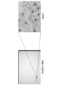
- FIG. 16 is a diagram illustrating a state in which a second feature amount E for each area is calculated for the image of the sample SPL illustrated in FIG. It is a figure which shows a mode that the 2nd feature-value E for every area was calculated by the continuation determination process about the image of another sample SPL shown in FIG. It is a figure which shows the image used in the specific example of curve fitting, and the small area
- FIG. 1 is a block diagram illustrating an overall configuration of a digital microscope apparatus 100 according to the present embodiment.
- the digital microscope apparatus 100 includes an overhead image imaging unit 10, an enlarged image imaging unit 20, a defocus amount detection unit 30, a stage 40, and a control unit 50.
- the overhead image capturing unit 10 captures an image of the entire preparation PRT on which the biological sample SPL is disposed (hereinafter, this image is referred to as “overhead image”).
- the enlarged image capturing unit 20 captures an image obtained by enlarging the biological sample SPL at a predetermined magnification (hereinafter, this image is referred to as “enlarged image”).
- the defocus amount detection unit 30 detects the amount and direction of deviation in the optical axis direction between the focal point of the objective lens 23 of the enlarged image capturing unit 20 and the biological sample SPL on the preparation PRT as the defocus amount.
- the stage 40 is for placing the preparation PRT and moving it to the imaging position by the overhead image imaging unit 10 and the imaging position by the enlarged image imaging unit 20.
- the stage 40 is driven by the stage drive mechanism 41 in the direction of the optical axis (Z-axis direction) of the objective lens 23 of the enlarged image capturing unit 20 and in the direction orthogonal to the direction of the optical axis (X-axis-Y-axis direction). It is supposed to be movable.
- the preparation PRT is obtained by fixing a biological sample SPL composed of tissue sections or smear cells such as connective tissue such as blood, epithelial tissue, or both of them to a slide glass by a predetermined fixing method. These tissue sections or smear cells are subjected to various stains as necessary.
- This staining includes not only general staining such as HE (hematoxylin and eosin) staining, Giemsa staining, Papanicolaou staining, Thiel-Neilsen staining, and Gram staining, but also FISH (Fluorescence® In-Situ Hybridization), enzyme antibody method, etc. Of fluorescent staining.
- the digital microscope apparatus 100 is provided with a preparation stock loader 70 for accumulating the preparation PRT including the sample SPL and loading the accumulated preparation PRT onto the stage 40 one by one.
- the preparation stock loader 70 may be incorporated in the digital microscope apparatus 100.
- the overhead image capturing unit 10 includes a light source 11, an objective lens 12, and an image sensor 13 as shown in the figure.
- the light source 11 is provided on the surface side opposite to the preparation arrangement surface of the stage 40.
- the overhead image capturing unit 10 may be separately provided with a label light source (not shown) that emits light for capturing supplementary information described in the label attached to the preparation PRT.
- the objective lens 12 is disposed on the preparation PRT arrangement surface side of the stage 40 with the normal line of the reference position of the overhead image capturing unit 10 on the preparation PRT arrangement surface as the optical axis SR.
- the transmitted light that has passed through the preparation PRT placed on the stage 40 is collected by the objective lens 12 and is connected to the image sensor 13 provided behind the objective lens 12 (that is, in the traveling direction of the illumination light). Image.
- the imaging device 13 forms an image of light in the imaging range that covers the entire preparation PRT placed on the preparation arrangement surface of the stage 40 (in other words, transmitted light that has transmitted through the entire preparation PRT).
- the image formed on the image sensor 13 becomes a bird's-eye view image that is a microscope image obtained by imaging the entire preparation PRT.
- the enlarged image capturing unit 20 includes a light source 21, a condenser lens 22, an objective lens 23, an imaging element 24, and a condenser lens driving mechanism 25 as shown in the drawing.
- the light source 21 emits bright field illumination light.
- the light source 21 is provided on the surface side opposite to the preparation arrangement surface of the stage 40.
- the condenser lens 22 is a lens that collects the light emitted from the light source of the bright field illumination light emitted from the light source 21 and guides it to the preparation PRT on the stage 40.
- the condenser lens 22 is disposed between the light source 21 and the stage 40 with the normal line of the reference position of the enlarged image capturing unit 20 on the preparation PRT arrangement surface as the optical axis ER.
- the condenser lens driving mechanism 25 changes the position of the condenser lens 22 on the optical axis ER by driving the condenser lens 22 along the optical axis ER direction.
- the objective lens 23 is arranged on the preparation PRT arrangement surface side of the stage 40 with the normal line of the reference position of the enlarged image capturing unit 20 on the preparation PRT arrangement surface as the optical axis ER.
- the magnified image capturing unit 20 it is possible to magnify and image the biological sample SPL at various magnifications by appropriately replacing the objective lens 23.
- the transmitted light that has passed through the preparation PRT placed on the stage 40 is collected by the objective lens 23 and is connected to the image sensor 24 provided behind the objective lens 23 (that is, in the traveling direction of the illumination light). Image.
- a beam splitter 31 is provided on the optical axis ER between the objective lens 23 and the image sensor 24.
- the beam splitter 31 guides part of the transmitted light that has passed through the objective lens 23 to the defocus amount detection unit 30.
- the imaging device 24 has an imaging range (hereinafter referred to as a small region) having a predetermined horizontal width and vertical width on the preparation PRT arrangement surface of the stage 40 according to the pixel size of the imaging device 24 and the magnification of the objective lens 23. An image is formed. Since a part of the biological sample SPL is enlarged by the objective lens 23, the above-described imaging range is a sufficiently narrow range compared to the imaging range of the image sensor 13.
- the defocus amount detection unit 30 includes a beam splitter 31, a field lens 32, a separator lens 33, and an image sensor 34.
- the beam splitter 31 is provided on the optical axis ER between the objective lens 23 of the enlarged image capturing unit 20 and the image sensor 24, and a part of the transmitted light transmitted through the objective lens 23. To reflect. In other words, the light that has passed through the objective lens 23 by the beam splitter 31 is branched into reflected light that travels toward the image sensor 24 and transmitted light that travels toward the field lens 32 in the defocus amount detection unit 30.
- a field lens 32 is provided on the traveling direction side of the transmitted light branched by the beam splitter 31.
- the field lens 32 collects the transmitted light branched by the beam splitter 31 and guides it to a separator lens 33 provided behind the field lens 32 (on the traveling direction side of the transmitted light).
- the separator lens 33 splits the light beam guided from the field lens 32 into two light beams.
- the divided light beams form a set of subject images on the imaging surface of the image sensor 34 provided behind the separator lens 33 (on the traveling direction side of the transmitted light).
- phase difference image The light that has passed through the separator lens 33 forms an image on the image sensor 34.
- a set of subject images is formed on the imaging surface of the imaging element 34.
- the light transmitted through the two separator lenses 33 is imaged by the single image sensor 34, but the light transmitted through the separator lens 33 may be captured by the two image sensors 34. Since light beams in various directions emitted from the field lens 32 are incident on the separator lens 33, there is a phase difference between a pair of formed subject images.
- this set of subject images is referred to as a “phase difference image”.
- the beam splitting means for splitting the beam is not limited to the beam splitter.
- a movable mirror or the like can also be used. It is also possible to use a mechanism that switches between the lens barrel of the enlarged image capturing unit 20 and the lens barrel of the defocus amount detection unit 30.
- phase difference AF optical system As the phase difference AF (Auto Focus) optical system in the defocus amount detection unit 30 is shown, but the present invention is limited to this example. Do not mean.
- phase difference AF optical system is another optical system as long as an equivalent function can be realized, for example, using a condenser lens and a binocular lens instead of a field lens and a separator lens. Also good.
- the imaging elements provided in each of the overhead image imaging unit 10, the enlarged image imaging unit 20, and the defocus amount detection unit 30 may be a one-dimensional imaging element or a two-dimensional imaging element.
- the control unit 50 includes an integrated control unit 51, an illumination control unit 52, a stage control unit 53, a condenser lens drive control unit 54, a phase difference image capturing control unit (phase difference AF detection unit) 55, and an overhead image capturing.
- the image forming apparatus includes a control unit 56, an enlarged image imaging control unit (enlarged image imaging unit) 57, a storage unit 58, a development processing unit 59, and an image encoding unit 60.
- the illumination control unit 52 performs irradiation control of the light sources 11 and 21 based on the instruction of the illumination method of the biological sample SPL given from the integrated control unit 51. For example, the illumination control unit 52 performs selection of the intensity of illumination light of the light sources 11 and 21 according to an instruction from the integrated control unit 51.
- the stage control unit 53 drives the stage drive mechanism 41 so that the entire preparation PRT falls within the imaging range of the image sensor 13, and the stage surface direction
- the stage 40 is moved in the (XY axis direction).
- the stage control unit 53 drives the stage driving mechanism 41 so that the objective lens 12 is focused on the entire preparation PRT, and moves the stage 40 in the Z-axis direction.
- the stage control unit 53 causes the imaging range (small area) of the instructed sample SPL to fall within the imaging range of the image sensor 24.
- the drive mechanism 41 is driven to move the stage 40 in the stage surface direction (XY axis direction).
- the stage control unit 53 drives the stage drive mechanism 41 so that the objective lens 23 is focused on the sample SPL, and moves the stage 40 in the Z-axis direction.
- the condenser lens drive control unit 54 controls the condenser lens drive mechanism 25 based on the information related to the defocus amount of the illumination field stop from the integrated control unit 51, thereby observing the illumination light from the light source 21 with the sample SPL. Adjust to hit only the range.
- Information about the illumination field stop includes a defocus amount and a defocus direction. These pieces of information are obtained based on the distance between a set of phase difference images generated by the defocus amount detection unit 30.
- the phase difference image imaging control unit 55 acquires a set of phase difference image signals formed on the imaging surface of the imaging element 34 provided in the defocus amount detection unit 30 and supplies the acquired signals to the integrated control unit 51.
- the integrated control unit 51 uses the objective lens 23 of the enlarged image capturing unit 20 based on the distance of the set of phase difference images acquired from the phase difference image capturing control unit 55 according to the program loaded in the main memory therein. A defocus amount and a defocus direction with respect to the sample SPL of the focus are calculated.
- the integrated control unit 51 generates control information for the stage 40 based on these pieces of information, and supplies the control information to the stage control unit 53.
- the stage control unit 53 drives the stage drive mechanism 41 so as to move the stage 40 in the Z-axis direction based on the control information from the integrated control unit 51. Thereby, the phase difference AF for adjusting the focus of the objective lens 23 of the enlarged image capturing unit 20 to the sample SPL is performed.
- the overhead image capturing control unit 56 generates data corresponding to the overhead image based on a signal corresponding to the overhead image formed on the imaging surface of the image pickup device 13 of the overhead image capturing unit 10, and the integrated control unit 51. To supply.
- the integrated control unit 51 performs a process of specifying a region where the sample SPL exists from the overhead image acquired from the overhead image capturing control unit 56 according to a program loaded in the main memory therein.
- the magnified image capturing control unit 57 is configured to generate data corresponding to the magnified image based on a signal corresponding to the magnified image for each photographing range (small region) formed on the imaging surface of the image sensor 24 of the magnified image capturing unit 20. Is generated and supplied to the integrated control unit 51.
- the integrated control unit 51 supplies, to the development processing unit 59, an enlarged image that is RAW data for each shooting range (small area) acquired from the enlarged image imaging control unit 57 in accordance with a program loaded in the main memory therein.
- a stitching process for executing development processing and joining the enlarged image data for each developed photographing range (small region) to the enlarged image of the sample SPL unit, and the enlarged image of the sample SPL unit generated thereby is called a tile.
- a process of dividing into units of a predetermined resolution is performed.
- the integrated control unit 51 supplies each tile generated by the division to the image encoding unit 60, generates image data in a predetermined compression encoding format, and stores the image data in the storage unit 58.
- the storage unit 58 stores information such as various setting information for controlling the digital microscope apparatus 100, a program, and the like.
- the storage unit 58 stores an enlarged image of the sample SPL obtained by the digital microscope apparatus 100 in units of a predetermined resolution called tiles.
- the development processing unit 59 develops an enlarged image that is RAW data for each shooting range (small area) captured by the enlarged image capturing unit 20.
- the developed enlarged images for each photographing range (small area) are connected by the integrated control unit 51 so as to become an enlarged image of the sample SPL unit, and the connected enlarged image of the sample SPL unit is a predetermined resolution called a tile. And is supplied to the image encoding unit 60.
- the image encoding unit 60 encodes an image for each tile in a predetermined image compression format.
- JPEG Joint
- a compression encoding format other than JPEG may be employed.
- the tile-unit image data compressed and encoded by the image encoding unit 60 is stored in the storage unit 58.
- the tiled enlarged image stored in the storage unit 58 is accumulated in the image management server 63 through the network 62 by the communication unit 61.
- the image management server 63 responds to the viewer terminal 64 with one or more corresponding enlarged images in tile units.
- the viewer terminal 64 can generate an enlarged image for display using the enlarged image of one or more tile units acquired from the image management server 63, and can display the enlarged image on the display of the viewer terminal 64.
- the digital microscope apparatus 100 is equipped with a phase difference autofocus method and a contrast autofocus method as autofocus methods for the objective lens 23 of the enlarged image capturing unit 20.
- a high-speed and accurate hybrid autofocus is achieved by combining a phase difference autofocus method and a contrast autofocus method using a CMOS imager for the image sensor 24 of the enlarged image capturing unit 20. The method is realized.
- the integrated control unit 51 instructs the phase difference image capturing control unit 55 to capture a phase difference image.
- the phase difference image capturing control unit 55 takes in a set of phase difference image signals formed side by side on the imaging surface of the image sensor 34 from the defocus amount detection unit 30. The phase difference of the phase difference image is obtained.
- the integrated control unit 51 obtains the distance between the same regions of the observation surface on the two phase difference images as the phase difference.
- the integrated control unit 51 obtains the defocus amount and the defocus direction with respect to the sample SPL that is the observation target of the focus of the objective lens 23 from the obtained phase difference.
- the integrated control unit 51 generates control information for the stage 40 based on the obtained defocus amount and defocus direction, and supplies the control information to the stage control unit 53.
- the stage control unit 53 drives the stage drive mechanism 41 so as to move the stage 40 in the Z-axis direction based on the control information from the integrated control unit 51.
- phase difference autofocus for adjusting the focus of the objective lens 23 of the enlarged image capturing unit 20 to the sample SPL is performed.
- the contrast autofocus method is a method of performing a focus search by a hill-climbing method using the enlarged image capturing unit 20.
- the integrated control unit 51 shifts the focal position of the objective lens 23 by a predetermined distance, and causes the enlarged image imaging unit 20 to perform imaging of the imaging range of the sample SPL at each focal position.
- the integrated control unit 51 determines the focal position when the image with the highest contrast among the captured images is captured as the optimal focal position.
- FIG. 2 is a functional block diagram illustrating functions for realizing control in the integrated control unit 51.
- the integrated control unit 51 performs control according to a program stored in the main memory in the integrated control unit 51.
- the integrated control unit 51 includes an area detection unit 511, a phase difference AF in-focus position calculation unit (phase difference AF processing unit) 512, and a contrast AF in-focus position calculation unit (search image acquisition unit, in-focus unit).
- (Focus position determination unit) 513, first feature amount calculation unit 514, curve fitting processing unit (curve fitting unit) 515, white image determination unit 516, second feature amount calculation unit 517, continuation determination unit 518, focus position A pass / fail determination unit (focus position determination unit) 519 is provided.
- the region detection unit 511 first partitions the overhead image acquired by the overhead image capturing control unit 56 using the overhead image capturing unit 10 into a mesh unit in units of size according to the field of view of the enlarged image capturing unit 20. Each partitioned area is the small area described above. Next, the region detection unit 511 determines whether or not an image of the sample SPL is captured in each small region. Then, the area detection unit 511 extracts a small area that is determined to have an image of the sample SPL, and generates a shooting list and shooting order information. In order to determine whether or not the image of the sample SPL is captured, for example, in the overhead view image, a small region in which the image of the sample SPL exists is determined from the distribution of pixels whose luminance values change sharply. For detecting a pixel whose luminance value changes sharply, for example, a method of detecting the boundary of the specimen by edge detection is used.
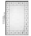
- the phase difference AF in-focus position calculation unit 512 defocuses the sample lens SPL of the objective lens 23 of the enlarged image imaging unit 20 based on the distance between the pair of phase difference images acquired from the phase difference image imaging control unit 55. The amount (focus position) and defocus direction are calculated. In addition, the phase difference AF in-focus position calculation unit 512 divides the imaging data of the phase difference image formed by the two separator lenses 33 into, for example, 8 ⁇ 6 areas, and detects a characteristic area. Thereafter, the phase difference AF in-focus position calculation unit 512 calculates the in-focus position for the areas having these features, and supplies the position information and the in-focus position of the areas having these features to the integrated control unit 51.
- the contrast AF in-focus position calculation unit 513 issues an instruction to the stage control unit 53 to change the position of the sample SPL in the Z-axis direction, and issues an instruction to the enlarged image imaging control unit 57 to enlarge the small area to be imaged. Take multiple images.
- the contrast AF focus position calculation unit 513 also supplies the captured image of the small area to the first feature value calculation unit 514, and causes the first feature value to be calculated for each image.
- the contrast AF focus position calculation unit 513 supplies the calculated first feature amount to the curve fitting processing unit 515, and obtains the focus position in the contrast AF method.
- the first feature amount calculation unit 514 calculates a first feature amount for the curve fitting processing unit 515 to obtain a focus position in the contrast AF method by curve fitting to a quadratic function. A method for calculating the first feature amount will be described later.
- the curve fitting processing unit 515 performs fitting on the quadratic curve of three or more first feature values supplied from the integrated control unit 51, and performs focusing in the contrast AF method from the position of the vertex of the quadratic curve. Calculate the position.
- the white image determination unit 516 determines whether or not the supplied enlarged image is an image (white image) in which the sample SPL is not captured at all. For the determination, the second feature value calculated by the second feature value calculation unit 517 is used. Details will be described later.
- the second feature amount calculation unit 517 determines whether the white image is determined by the white image determination unit 516 or whether the sample SPL image is present in the small region following (adjacent to) the small region to be imaged by the continuation determination unit 518. In the determination, a second feature amount used as an index is calculated. A method for calculating the second feature amount will be described later.
- the continuation determination unit 518 determines whether or not there is an image of the sample SPL also in the small area that is next (adjacent) to the small area that is currently the subject of the enlarged shooting. For the determination, the second feature value calculated by the second feature value calculation unit 517 is used. Details will be described later.
- the in-focus position acceptance / rejection determination unit 519 determines whether the in-focus position by the phase difference AF method calculated by the phase difference AF in-focus position calculation unit 512 is within a predetermined allowable range (passed) ( Fail). At the time of determination, the in-focus position pass / fail determination unit 519 issues an instruction to the stage control unit 53 to change the position of the sample SPL in the Z-axis direction, and issues an instruction to the enlarged image capturing control unit 57 to detect a small object to be imaged. A plurality of enlarged images of the area are taken. The in-focus position acceptance / rejection determination unit 519 also supplies the captured image of the small region to the first feature amount calculation unit 514 to calculate the first feature amount for each image.
- the in-focus position pass / fail determination unit 519 determines that the in-focus position by the phase difference AF method is acceptable when the relationship between the calculated first feature value values satisfies a predetermined relational expression.
- the in-focus position that has passed is used for the actual photographing of the enlarged image.
- FIG. 3 is a flowchart for explaining the overall processing flow in the digital microscope apparatus 100 of the present embodiment.
- the difference between this technology and the conventional hybrid AF method is as follows.
- the in-focus position is obtained by the two methods of the phase difference AF method and the contrast AF method, and if both values are close to each other, the reliability of the in-focus position is high, and the positioning of both AF methods is the same. is there.
- the calculated focus position is inaccurate depending on the type of the sample SPL, but the time required for searching the focus position is overwhelmingly short, and the focus position The time required for the search is long, but the features of the contrast AF method with high accuracy of the calculated in-focus position are combined.
- a temporary in-focus position is first obtained by the phase difference AF method, and a validity of the temporary in-focus position is confirmed by a simplified contrast AF method.
- the phase difference AF can detect (characteristic) the area where the sample SPL exists on the image to be captured, and the contrast AF of the present technology is performed only in that area.
- a decrease in image acquisition speed due to the contrast AF method is minimized.
- the integrated control unit 51 issues an instruction to the overhead view image capturing control unit 56 to photograph the overhead view image of the preparation PRT. (Step S1)
- the region detection unit 511 partitions the captured overhead image into a mesh shape in units of size according to the field of view of the enlarged image capturing unit 20. Each partitioned area is the small area described above.
- the region detection unit 511 determines whether or not an image of the sample SPL is captured in each small region. Then, the region detection unit 511 extracts a small region that is determined to have an image of the sample SPL, and determines a shooting list and shooting order information. (Step S3)
- the region detection unit 511 performs the above process for the following reason. Assuming that the digital microscope apparatus 100 uses the objective lens 23 with an optical magnification of 20 times, when the imaging surface of the imaging device 24 of the enlarged image imaging unit 20 is 37 mm ⁇ 25 mm in size, it is 1. on the preparation PRT at a time. A range of 87 mm ⁇ 1.24 mm can be photographed. The size of the imaging region on the preparation PRT is larger than that and is 60 mm ⁇ 25 mm. Therefore, the shooting area is divided into a plurality of small areas, and the movement of the stage 40 and the shooting of the small area are repeated a plurality of times to shoot the entire shooting area, and the images obtained by shooting the small areas are bonded together.
- a large image is taken by combining it with an image.
- a margin (pay margin) of at least 5% to 20% is required for combining the images to be pasted. Therefore, when photographing a small area, the peripheral part is formed between adjacent small area images. Take pictures so that they overlap.
- the integrated control unit 51 instructs the stage control unit 53 to move the stage 40 so that the first small area of the photographing list is directly below the objective lens 23. (Step S5)
- the integrated control unit 51 provides the stage control unit 53 with position information of each small area to be imaged.
- the stage control unit 53 drives the stage driving mechanism 41 based on the given position information of the imaging target area so that the small area to be captured falls within the imaging range of the enlarged image imaging unit 20.
- the stage 40 is moved.
- the position of the stage 40 in the Z direction is the position closest to the objective lens 23. By positioning at this Z position, it is possible to move the stage in a direction in which the stage 40 is moved away from the objective lens 23 in the search for the in-focus position by the contrast AF method. However, even when the distance between the stage 40 and the objective lens 23 is the shortest, an interval of 50 ⁇ m or more is provided.
- the preparation PRT transported directly below the objective lens 23 is irradiated with transmitted illumination from the light source 21.
- the transmitted light that has passed through the sample SPL on the preparation PRT enters the imaging element 24 of the enlarged image imaging unit 20 and the imaging element 34 of the defocus amount detection unit 30 via the objective lens (imaging lens) 23 and the like. To do.
- Step S7 the integrated control unit 51 performs calibration processing of phase difference AF and contrast AF.
- the calibration process is an indispensable process in the digital microscope apparatus 100 of the present embodiment that calculates the in-focus position by the hybrid AF method that uses both the phase difference AF method and the contrast AF method. By this processing, an offset value for correcting a shift between the in-focus position in the phase difference AF method and the in-focus position in the contrast AF method is obtained. Details of the calibration process will be described later.
- Step S9 the integrated control unit 51 performs a small area main photographing using the in-focus position obtained by the calibration process.
- the actual photographing is performed when the integrated control unit 51 issues an instruction to the enlarged image capturing control unit 57.
- Step S10 the integrated control unit 51 issues an instruction to the white image determination unit 516 to perform white image determination processing.
- the integrated control unit 51 determines whether or not the image obtained by actually photographing the small area used for the calibration is a white image. (Step S11)
- the integrated control unit 51 does not need to include the image of the sample SPL in the white image, and therefore does not need to be included in the finally stored image.
- a white image flag is set so as not to be processed in later processing.
- the integrated control unit 51 After setting the white image flag, the integrated control unit 51 returns the process to step S5 in order to move the stage 40 so that the next small area of the shooting list is directly below the objective lens 23.
- Step S15 If it is not a white image (N in Step S11), as the next step, the integration control unit 51 issues an instruction to the continuation determination unit 518 and performs a continuation determination process. (Step S15)
- the continuation determination process whether or not the image of the sample SPL is captured in each small region performed by the region detection unit 511 in step 3 by verifying an image of a margin (described later) portion of the captured image. The determination of whether or not is verified. By this processing, it is possible to reduce the missed image of the sample SPL.
- the integrated control unit 51 issues an instruction to the development processing unit 59 to perform the development processing of the actually captured image. (Step S19)
- Step S21 the integrated control unit 51 performs stitching processing on the actually captured image.
- the integrated control unit 51 determines whether or not the main shooting and the process associated with the main shooting have been completed for all the small areas listed in the shooting list. (Step S23)
- the integrated control unit 51 determines that the next small area in the shooting list is the objective.
- the stage controller 53 is instructed to move the stage 40 so that it is directly under the lens 23.
- the integrated control unit 51 performs a focus position calculation process in order to calculate a focus position for actual photographing of a small area newly positioned directly below the objective lens 23.
- the in-focus calculation processing is to calculate the in-focus position by a hybrid AF method that combines a phase difference AF method and a contrast AF method. Details will be described later.
- the integrated control unit 51 performs the main imaging of the small area using the in-focus position obtained in the in-focus calculation process.
- the actual photographing is performed when the integrated control unit 51 issues an instruction to the enlarged image capturing control unit 57.
- the integrated control unit 51 issues an instruction to the white image determination unit 516 to perform white image determination processing.
- the white image determination process performed here is different from the white image determination process performed after the calibration process, and has no meaning to determine the validity of the calibration. It is simply for raising a white image flag.
- the integrated control unit 51 determines whether or not the image obtained by actually photographing the small area is a white image.
- the integration control unit 51 sets a white image flag so that the white image is not included in the image to be finally stored. (Step S33)
- Step S35 When all the main shooting and the processes accompanying the main shooting have been completed for all the small areas listed in the shooting list (Y in step S23), the integrated control unit 51 issues an image encoding unit 602 instruction, A huge image synthesized after the stitching process is divided into tiles, and the divided images are encoded and compressed. (Step S35)
- Step S37 the integrated control unit 51 saves the compressed tile image in the storage unit 58.
- FIG. 4 is a flowchart for explaining the flow of the calibration process.
- the phase difference AF focus position calculation unit 512 calculates a focus position Z1 in the phase difference AF method.
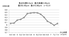
- the contrast AF focus position calculation unit 513 sets the Z-axis direction positions ZA, ZB, ZC, and (ZA>ZB> ZC), for example, by setting the interval in the Z-axis direction for rough search to 25 ⁇ m. To do. Further, a threshold value for rough search is set in the first feature amount calculation unit 514. (Step S43) In contrast AF, first a rough search is performed to find a Z position that is roughly focused.
- the contrast AF focus position calculation unit 513 issues an instruction to the stage control unit 53, and moves the stage 40 so that the position of the stage in the Z direction becomes the one set in step S43. (Step S45)
- the stage 40 is moved in a direction away from the objective lens 23 in the Z direction in units of 25 ⁇ m.
- the contrast AF in-focus position calculation unit 513 issues an instruction to the enlarged image capturing control unit 57 and captures an image of a small area as a search capturing.
- the enlarged image imaging control unit 57 reads out pixel values for all pixels (all angle of view) from the image sensor 24 of the enlarged image imaging unit 20.
- the image data remains as RAW data. Note that a total of three images corresponding to the three Z positions are taken.
- the contrast AF in-focus position calculation unit 513 determines whether or not a search image has been captured at all the set positions in the Z direction.
- step S49 If not all necessary images have been captured (N in step S49), the process returns to step S45 and the process is repeated.
- Step S51 the contrast AF focus position calculation unit 513 issues an instruction to the first feature value calculation unit 514, and the first feature value. H is calculated.
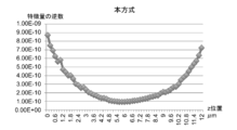
- the first feature amount H is calculated for each image. Since there are three images, curve fitting to a quadratic curve can be performed by setting the reciprocal of the first feature amount H to three points on the graph. Since the quadratic curve has a vertex that is focused at the position where the first feature amount H is the largest (the reciprocal is the smallest), the in-focus position can be obtained. A method for calculating the first feature amount H will be described later.
- the contrast AF in-focus position calculation unit 513 determines whether or not the three images have been processed.
- the contrast AF in-focus position calculation unit 513 uses the calculated first feature amount H to instruct the curve fitting processing unit 515 to perform the curve fitting processing.
- the reciprocal of the first feature amount H is taken, and fitting is performed on a downwardly convex quadratic curve.
- the contrast AF focus position calculation unit 513 calculates the focus position Z2 from the position of the vertex of the secondary curve by curve fitting.
- the above is the flow of the rough search process.
- the in-focus position Z2 obtained by the processing so far includes an error of about ⁇ 3 ⁇ m.
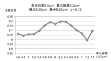
- a fine search process using a contrast AF method is performed. In the following description, the procedure of fine search using the focus position Z2 by the contrast AF focus position calculation unit 513 will be described.
- the contrast AF in-focus position calculation unit 513 sets the Z-axis direction positions ZA, ZB, and the Z-axis direction intervals for fine search at intervals of ⁇ 3 ⁇ m, for example, with the in-focus position Z2 as the center.
- ZC (ZA>ZB> ZC) is set.
- the contrast AF in-focus position calculation unit 513 sets a fine search threshold value in the first feature amount calculation unit 514.
- the contrast AF focus position calculation unit 513 issues an instruction to the stage control unit 53, and moves the stage 40 so that the position of the stage in the Z direction is the one set in step S69. (Step S71)
- the contrast AF in-focus position calculation unit 513 issues an instruction to the enlarged image capturing control unit 57 and captures an image of a small area as a search capturing.
- the enlarged image capturing control unit 57 reads out pixel values for all pixels (all angles of view) from the image sensor 24 of the enlarged image capturing unit 20. A total of three images corresponding to the three Z positions are taken.
- the contrast AF in-focus position calculation unit 513 determines whether or not a search image has been captured at all the set positions in the Z direction.
- step S75 If not all necessary images have been captured (N in step S75), the process returns to step S71 and the process is repeated.
- Step S79 the contrast AF focus position calculation unit 513 issues an instruction to the first feature value calculation unit 514, and the first feature value. H is calculated.
- the contrast AF in-focus position calculation unit 513 determines whether or not the three images have been processed.
- the contrast AF in-focus position calculation unit 513 uses the calculated first feature amount H to instruct the curve fitting processing unit 515 to perform the curve fitting processing.
- the contrast AF focus position calculation unit 513 calculates the focus position Z3 from the vertex position of the secondary curve by curve fitting.
- the integrated control unit 51 calculates the difference between the focus positions Z1 and Z3 as an offset value due to the difference in AF method. (Step S95)
- the AF offset value calculated here is used for conversion when the focus position obtained by the phase difference AF method is used by the contrast AF method in the focus position calculation process.
- the calibration process flow has been described above.
- FIG. 5 is a flowchart for explaining the flow of the first feature amount H calculation process.
- the first feature amount calculation unit 514 reads the pixel value for one block from the entire target RAW image or the divided area. (Step S101)
- 1 block is composed of i pixels in the vertical direction and j pixels in the horizontal direction (i and j are predetermined integers) among the arrangement of pixels of the same color. For example, as shown in FIG. 6 for the red plane and as shown in FIG. 7 for the Bayer array, one vertical and eight horizontal areas of red pixels can be made into one block.
- FIG. 8 is an example of a pixel used when a feature amount is obtained on a red plane.
- FIG. 9 is an example of pixels used when red feature values are obtained in a Bayer array.
- the first feature quantity calculation unit 514 obtains the maximum value and the minimum value from the pixel values of the respective pixels in the read block. Then, the DC component value DC and the dynamic range DR of the AC component are obtained from the following equations. (Step S103)
- DC component DC (minimum value)
- AC component dynamic range DR (maximum value)-(minimum value)
- FIG. 10 is a diagram showing an example of obtaining the dynamic range DR of the direct current component DC and the alternating current component.
- the first feature value calculation unit 514 determines whether or not the obtained DC and DR exceed a threshold value (whether or not the first condition and the second condition are satisfied).
- the reason why the DRt_min of the coarse search is set to 128 is that, in the case of the coarse search, since the search is performed for a long distance, it is desired to suppress the attenuation of the first feature amount, but it is desired to cut the noise included in the white portion at the minimum. Because of the intention. There is a so-called shot noise in the image sensor, and this appears for the square root of the signal intensity. Since the maximum value of the pixel value is 4096 in the case of an image sensor with a 12-bit output, the noise magnitude can be obtained as 64 from the following equation.
- the first feature value calculation unit 514 employs the dynamic range DR as the unit feature value of the block.
- the first feature quantity calculation unit 514 adds the unit feature quantity adopted in the previous step to the first feature quantity H. (Step S109)
- the sum total of the dynamic range DR is used as the first feature amount H.
- the value shown in FIG. 11 can be adopted as the first feature amount H.
- the first feature amount calculation unit 514 determines whether the feature amount has been calculated for all pixels. (Step S111)
- step S111 For all the pixels, if the feature quantity has not been calculated yet (N in step S111), the process returns to step S101 and the process is continued for the next block.
- a pixel position shifted by k pixels (k is a predetermined integer of 1 or more) from the previous start point is used. For example, in the case of a block of 1 pixel in the vertical direction and 8 pixels in the horizontal direction, the start point may be shifted by 1 pixel, or may be shifted by 8 pixels.
- the total number of calculations can be reduced, and the change in feature amount can be moderated, so a curve more suitable for fitting can be formed. it can.
- the first feature quantity calculation unit 514 determines whether or not the value of the first feature quantity H obtained by adding all the unit feature quantities is extremely small. (Step S113)
- the first feature amount calculation unit 514 changes the threshold values DCt and DRt in a direction in which the filter effect is reduced. (Step S115)
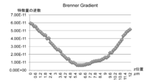
- the first feature amount calculation unit 514 obtains the value of Brenner Gradient for the entire target RAW image or the segmented area.
- the first feature quantity calculation unit 514 adds the obtained Brenner Gradient value to the extremely small first feature quantity H value.
- the feature amount using the dynamic range DR has a property that the value is greatly reduced when the focus is shifted.
- the Brenner Gradient is also the sum of the squares of adjacent pixel differences, the change in the feature amount is rapid as in the dynamic range DR. For this reason, if both of them are used at the same time, the feature of a sudden change in the feature amount becomes conspicuous, and if used for fitting, the error may increase.
- the first feature amount H is extremely small because the sample SPL is small or the like, and if it is desired to increase this value as much as possible, Brenner Gradient is also used. In this way, by selecting a feature amount calculation method that matches the state of the image for which the first feature amount H is obtained, it is possible to further improve the focusing accuracy.
- the flow of the first feature amount H calculation process has been described above.
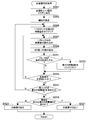
- FIG. 12 is a flowchart for explaining the flow of the in-focus position calculation process.
- the in-focus position is quickly obtained by the phase difference AF method, and the validity of the position is verified by the contrast AF method.
- the contrast AF method As a result of the verification, when the in-focus position obtained by the phase difference AF method is appropriate, the position is adopted for the actual photographing.
- the in-focus position obtained by the phase difference AF method is not appropriate, the in-focus position is obtained again by the contrast AF method.
- the phase difference AF focus position calculation unit 512 calculates a focus position Z1 in the phase difference AF method.
- the small area to be photographed is divided into m ⁇ n areas (m and n are predetermined integers of 1 or more), and the presence / absence of the feature is determined for each area. Find the location information of an area with The obtained position information is used when band reading (partially reading) pixel values from the image sensor 24 of the enlarged image capturing unit 20 in a later step.
- the in-focus position pass / fail determination unit 519 sets the Z-axis direction positions ZA, ZB, ZC, and the Z-axis direction for verification at intervals of, for example, ⁇ 1 ⁇ m around the in-focus position Z1. (ZA>ZB> ZC) is set. (Step S203)
- the in-focus position pass / fail determination unit 519 sets a fine search threshold value in the first feature amount calculation unit 514 as a verification threshold value.
- the in-focus position acceptance / rejection determination unit 519 instructs the stage control unit 53 to move the stage 40 so that the position of the stage in the Z direction becomes the one set in step S203.
- the in-focus position pass / fail determination unit 519 issues an instruction to the enlarged image capturing control unit 57, and captures an image of a small area as verification shooting.
- the enlarged image imaging control unit 57 divides the imaging surface of the image sensor 24 of the enlarged image imaging unit 20 into m ⁇ n areas as in step S201, and has a characteristic based on the position information obtained in step S201. Partial reading (band reading) of only the pixel values of the area is performed. Since the reading is partial and the amount of data to be processed in the subsequent processing is reduced, the processing time required for the verification process can be shortened. Note that a total of three images corresponding to the three Z positions are taken.
- the in-focus position pass / fail determination unit 519 determines whether or not verification images have been captured at all the set positions in the Z direction.
- step S211 If all necessary images have not been picked up (N in step S211), the process returns to step S207 and is repeated.
- Step S213 When all necessary images have been captured (Y in step S211), as the next step, the in-focus position acceptance / rejection determination unit 519 issues an instruction to the first feature amount calculation unit 514, and the first feature amount H Is calculated. (Step S213)
- step S213 in addition to the first feature amount H, a feature amount Gmn (area feature amount Gmn) for each area having a feature may be obtained.
- Step S215) the focus position pass / fail determination unit 519 determines whether or not three images have been taken.
- the first feature amount H is calculated for each image. Corresponding to the three Z positions ZA, ZB, and ZC, the first feature amount H is obtained as HA, HB, and HC.
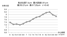
- FIG. 13 shows a point A (ZA, HA), point B (ZB, HB), point C (ZC, Z) on the two-dimensional plane, with the Z position as the horizontal axis and the inverse of the first feature amount H as the vertical axis.
- HC is plotted in three points.
- the in-focus position acceptance / rejection determination unit 519 determines whether or not HB is the maximum among the three first feature amounts H. (Step S217)
- the focus position acceptance / rejection determination unit 519 employs the focus position Z1 obtained by the phase difference AF method as the focus position for the main photographing. (Step S219)
- Step S221) determines that the inclination between the three points (points A, B, and C) satisfies the following conditional expression. Determine whether or not.
- the conditional expression expresses the slope between point A and point B as slope AB, and L is a predetermined value, When slope AB> slope BC, L>
- the in-focus position acceptance / rejection determination unit 519 employs the in-focus position Z1 obtained by the phase difference AF method as the in-focus position for the main photographing. . (Step S219)
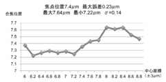
- curve fitting is performed using the first feature amount H and a plurality of area feature amounts Gmn to obtain the in-focus position ZH and the in-focus position ZGmn.
- the shift of the focus position at the boundary is minimized.
- One is selected from a plurality of in-focus positions ZGmn. When selecting, ZGmn whose value is extremely different from the in-focus position ZH is excluded from the selection candidates.
- the in-focus position ZGmn in the peripheral area is adopted as the in-focus position for the actual photographing.
- the focus position ZGmn in the area near the center is adopted as the focus position for the actual photographing.
- the in-focus position ZH is adopted as the in-focus position.
- the area feature amount Gmn is obtained for each area, and the focus position is finely adjusted according to the state of the value, thereby making it possible to obtain a boundary at the time of image pasting compared to obtaining only one feature amount for one small area image. You can make the seam inconspicuous.
- This method makes it possible to obtain a focus position with a focus error suppressed to 0.8 ⁇ m.
- step S221 If the inclination between the three points does not satisfy the conditional expression (N in step S221), the in-focus position Z1 obtained by the phase difference AF method cannot be adopted as the in-focus position for the actual photographing.
- step 519 control is transferred to the contrast AF focus position calculation unit 513, and the focus position is calculated by the contrast AF method. Note that the in-focus position does not greatly deviate from the in-focus position of the adjacent small region that has already been obtained, so basically the coarse search is not performed and the fine search is started.
- the contrast AF focus position calculation unit 513 sets the Z-axis direction positions ZA, ZB, and the Z-axis direction intervals for fine search, for example, at ⁇ 3 ⁇ m intervals around the focus position Z1.
- ZC, (ZA>ZB> ZC) is set.
- the threshold value for fine search is set in step S203, and is not set again.
- the contrast AF in-focus position calculation unit 513 issues an instruction to the stage control unit 53, and moves the stage 40 so that the position of the stage in the Z direction becomes the one set in step S223. (Step S225)
- the contrast AF in-focus position calculation unit 513 issues an instruction to the enlarged image capturing control unit 57 and captures an image of a small area as a search capturing. (Step S227)
- the enlarged image imaging control unit 57 reads out pixel values for all pixels (all angle of view) from the image sensor 24 of the enlarged image imaging unit 20.
- pixel values are read for the minimum necessary area based on the position information obtained by the phase difference AF method.
- the in-focus position by the phase difference AF method cannot be adopted, it is determined that the position information obtained by the phase difference AF method is not reliable, and the entire area (the entire image is not a partial reading based on the position information). Pixel values are read for (corner). Note that a total of three images corresponding to the three Z positions are taken.
- the contrast AF in-focus position calculation unit 513 determines whether or not a search image has been captured at all the set positions in the Z direction.
- step S229 If not all necessary images have been captured (N in step S229), the process returns to step S225 and the process is repeated.
- Step S231 When all the necessary images have been captured (Y in step S229), as the next step, the contrast AF focus position calculation unit 513 issues an instruction to the first feature value calculation unit 514, and the first feature value H is calculated. (Step S231)
- the contrast AF in-focus position calculation unit 513 determines whether or not the three images have been processed.
- the contrast AF in-focus position calculation unit 513 uses the calculated first feature amount H to instruct the curve fitting processing unit 515 to perform the curve fitting processing.
- the contrast AF focus position calculation unit 513 calculates the focus position Z2 from the vertex position of the quadratic curve by curve fitting, and uses the calculated focus position Z2 as the focus position for actual photographing. To adopt. (Step S237)
- the contrast AF focus position calculation unit 513 may perform the process from the coarse search again, or the main image of the adjacent small area is captured. If there is information on the in-focus position, that information may be interpolated and used.
- the processing time for phase difference AF is 20 msec
- the processing time for pass / fail determination shooting (partial readout, 10% of the characteristic areas for all angles) is 3 times. 51 msec
- the processing time for fine search shooting (reading of all angles of view, for 3 images) is 510 msec.
- FIG. 14 is a flowchart for explaining the flow of the white image determination process.
- the white image determination unit 516 divides the entire small area image obtained by shooting into p ⁇ q areas (p and q are predetermined positive integers).
- the white image determination unit 516 sets a threshold value used by the second feature amount calculation unit 517.
- the second feature quantity calculation unit 517 clears the second feature quantity E for the area to be processed to zero.
- the second feature amount calculation unit 517 reads pixel values for one block. (Step S307)
- the second feature quantity calculation unit 517 calculates the DC component DC and the dynamic range DR. (Step S309)
- the calculation method of the direct current component DC and the dynamic range DR is the same as the method for calculating the first feature amount, and thus description thereof is omitted here.
- the second feature quantity calculation unit 517 determines whether or not the calculated DC component DC and dynamic range DR satisfy the following conditional expression.
- DCt_min is the minimum threshold for DC component DC
- DCt_max is the maximum threshold
- DRt_min is the minimum threshold for dynamic range DR
- DRt_max is the maximum threshold.
- the second feature value calculation unit 517 increments the second feature value E. (Step S313)
- the second feature quantity calculation unit 517 determines whether or not processing has been performed for all pixels. (Step S315)
- step S315 If all the pixels have not yet been processed (N in step S315), the process returns to step S307, and the process is continued for the next block.
- the white image determination unit 516 determines whether or not the second feature amount E has been calculated for all areas. (Step S317)
- step S317 If the second feature value E has not yet been calculated for all areas (N in step S317), the process returns to step S305 to continue the process for the next area.
- the white image determination unit 516 includes the second feature amount that has exceeded the sample presence confirmation threshold Et. It is determined whether or not E exists. (Step S319)
- FIG. 16 shows a state in which the second feature amount E for each area is calculated by the white determination processing for the image of the sample SPL that has been stained with HE (hematoxylin and eosin) shown in FIG.
- HE hematoxylin and eosin
- FIG. 18 shows how the second feature amount E for each area is calculated by the white determination processing for another HE-stained sample SPL image shown in FIG.
- the white image determination unit 516 includes the sample SPL in the captured image, and the white image Judge that there is no. (Step S321)
- the white image determination unit 516 determines that the captured image is a white image in which the sample SPL is not captured. judge. (Step S323)
- a white image flag is set and is not set as a processing target after the subsequent development processing, thereby shortening the processing time and the image storage capacity.
- the flow of the white image determination process has been described above.
- FIG. 19 is a flowchart for explaining the flow of the continuation determination process.
- the continuation determination unit 518 divides the peripheral portion (margin portion) of the small region image obtained by photographing into p areas (p is a predetermined integer of 2 or more).
- the continuation determination unit 518 sets a threshold value used by the second feature amount calculation unit 517. (Step S403)
- the second feature quantity calculation unit 517 clears the second feature quantity E for the area to be processed to zero.
- the second feature amount calculation unit 517 reads pixel values for one block. (Step S407)
- the second feature quantity calculation unit 517 calculates the DC component DC and the dynamic range DR. (Step S409)
- the calculation method of the direct current component DC and the dynamic range DR is the same as the method for calculating the first feature amount, and thus description thereof is omitted here.
- the second feature quantity calculation unit 517 determines whether or not the calculated DC component DC and dynamic range DR satisfy the following conditional expression.
- DCt_min is the minimum threshold for DC component DC
- DCt_max is the maximum threshold
- DRt_min is the minimum threshold for dynamic range DR
- DRt_max is the maximum threshold.
- the second feature quantity calculation unit 517 increments the second feature quantity E. (Step S413)
- the second feature quantity calculation unit 517 determines whether or not processing has been performed for all pixels. (Step S415)
- step S415) If all the pixels have not been processed yet (N in step S415), the process returns to step S407, and the process is continued for the next block.
- the continuation determination unit 518 determines whether or not the second feature amount E has been calculated for all areas. (Step S417)
- step S417 If the second feature value E has not yet been calculated for all areas (N in step S417), the process returns to step S405, and the process continues for the next area.
- FIG. 20 shows a state in which the second feature amount E for each area is calculated for the image of the sample SPL shown in FIG.
- FIG. 21 shows how the second feature amount E for each area is calculated by the subsequent determination process for the image of another sample SPL shown in FIG.
- the continuation determination unit 518 confirms the presence of the sample for each second feature amount E in each area. It is determined whether the threshold value Et has been exceeded. (Step S419)
- Step S421) When the second feature amount E exceeds the sample presence confirmation threshold Et (Y in step S419), the continuation determination unit 518 adds a small region adjacent to the area to the shooting list. (Step S421)
- the continuation determination unit 518 determines whether or not the determination in step S417 has been performed for all areas. (Step S423)
- step S417 If the determination in step S417 has not been made for all areas (N in step S423), the process returns to step S417, and the process is continued for the remaining areas.
- FIG. 22 is a diagram showing an image used in the following specific example and a small region in which a part thereof is enlarged.
- FIG. 23 is a diagram in which the reciprocal of the feature amount obtained by the conventional method of the images captured in the Z direction for the small area shown in FIG. 22 is plotted according to the shooting position.
- FIG. 24 is a diagram in which the reciprocal of the feature amount obtained by the present method is plotted according to the photographing position of the plurality of images photographed in the Z direction for the small region shown in FIG.
- FIG. 25 is a graph of the in-focus position according to the conventional method, obtained by performing curve fitting based on the curve plotted in FIG.
- FIG. 26 is a graph of the in-focus position according to this method obtained by performing curve fitting based on the curve plotted in FIG.
- ⁇ in the figure indicates a small variation in focus position.
- ⁇ 0.31
- the value of the calculated focus position varies depending on the three Z positions selected for the search, so that when the divided images are combined, the image is focused at the boundary where the images are pasted together. This results in a noticeable shift.
- the maximum error is 0.29 ⁇ m in this method, compared to 0.49 ⁇ m in the conventional method. This method shows higher performance.
- FIGS. 28 to 31 and FIGS. 33 to 36 Further, the verification results of the two images are shown in FIGS. 28 to 31 and FIGS. 33 to 36.
- FIG. 27 is a diagram showing another image and a small region in which a part thereof is enlarged.
- FIG. 28 is a diagram in which the reciprocal number of the feature amount obtained by the conventional method is plotted according to the photographing position of the plurality of images photographed in the Z direction for the small region shown in FIG.
- FIG. 29 is a diagram in which the reciprocal of the feature amount obtained by the present method of the images captured in the Z direction for the small area shown in FIG. 27 is plotted according to the shooting position.
- FIG. 30 is a graph of the in-focus position according to the conventional method, obtained by performing curve fitting based on the curve plotted in FIG.
- FIG. 31 is a graph of the in-focus position according to this method, obtained by performing curve fitting based on the curve plotted in FIG.
- FIG. 32 is a diagram showing still another image and a small region in which a part thereof is enlarged.
- FIG. 33 is a diagram in which the reciprocal of the feature amount obtained by the conventional method of the images captured in the Z direction for the small region shown in FIG. 32 is plotted according to the shooting position.
- FIG. 34 is a diagram in which the reciprocal of the feature amount obtained by the present method of the images captured in the Z direction for the small region shown in FIG. 32 is plotted according to the shooting position.
- FIG. 35 is a graph of the in-focus position according to the conventional method, obtained by performing curve fitting based on the curve plotted in FIG.
- FIG. 36 is a graph of the in-focus position according to the present method, obtained by performing curve fitting based on the curve plotted in FIG.
- this technique can also take the following structures.
- An image acquisition unit for search for acquiring enlarged images at different focal positions;
- a first feature amount calculation unit that obtains a first feature amount based on a dynamic range of a direct current component and an alternating current component of a pixel value for each block constituting the enlarged image for each of the plurality of captured enlarged images;
- An in-focus position determining unit that determines an in-focus position of the enlarged image based on the first feature amount.
- the first feature amount calculation unit is configured so that the dynamic range of the AC component satisfies a predetermined first condition and the DC component satisfies a predetermined second condition according to the block.
- An information processing apparatus for obtaining a first feature amount (3) The information processing apparatus according to (2), The first feature amount calculation unit calculates and adds unit feature amounts by a predetermined method for the blocks satisfying the first condition and the second condition, and based on the sum result, An information processing apparatus for obtaining a first feature amount for each enlarged image.
- the in-focus position determination unit sets the focal position calculated by the curve fitting unit as an in-focus position.
- the information processing apparatus (4), The predetermined curve is a quadratic curve.
- the information processing apparatus (6) The information processing apparatus according to any one of (1) to (5), The information processing apparatus that calculates the first feature amount based on a minimum value of pixel values for each block and a difference value between the maximum value and the minimum value.
- the information processing apparatus according to (3), The first feature quantity calculation unit uses the dynamic range as the unit feature quantity.
- the information processing apparatus according to (3), The information processing apparatus using the Brenner Gradient as the unit feature amount.
- the search image acquisition unit acquires a coarse search enlarged image at three or more focal positions separated by a first interval for roughly searching for a focus position
- the first feature amount calculation unit obtains the first feature amount for each of the coarse search enlarged images
- the in-focus position determination unit obtains an in-focus position for rough search
- the search image acquisition unit has three or more points separated by a second interval narrower than the first interval for finely searching the in-focus position with the in-focus position of the coarse search as a center.
- the first feature amount calculation unit obtains the first feature amount for each enlarged image for fine search
- the in-focus position determination unit obtains an in-focus position for fine search, and sets the in-focus position for fine search as a final in-focus position.
- the search image acquisition unit acquires enlarged images at three or more different focal positions
- the first feature amount calculation unit divides each of the acquired plurality of enlarged images into m ⁇ n (m and n are integers of 2 or more) first areas, and Find the first feature
- the in-focus position determination unit obtains an in-focus position for each first area, obtains an inclination of the specimen from the in-focus position for each area, and selects a final in-focus position based on the inclination. Processing equipment.
- the information processing apparatus When the sum is smaller than a predetermined value, An information processing apparatus that obtains Brenner Gradient of the enlarged image and sets the first feature amount in addition to the summation result. (12) The information processing apparatus according to any one of (1) to (8), A phase difference AF processing unit for detecting the phase difference focus position is further included in the phase difference AF detection unit for detecting the focus position by the phase difference AF (autofocus) method, The search image acquisition unit acquires enlarged images at three or more different focal positions including the phase difference in-focus position therebetween.
- the in-focus position determination unit has a predetermined relationship in which the first feature amount at the phase difference in-focus position is maximum, and a reciprocal of the first feature amount at the focus position is predetermined.
- the information processing apparatus sets the phase difference focus position as a final focus position.
- a phase difference AF processing unit for detecting a phase difference focus position in a phase difference AF detection unit that detects a focus position by a phase difference AF (autofocus) method;
- An enlarged image capturing unit that captures an enlarged image of the small region for a plurality of small regions that divide the region including the specimen on the slide glass;
- the search image acquisition unit is for coarse search at three or more focal positions separated by a first interval for coarsely searching for a focus position in a first small area of the plurality of small areas.
- the first feature amount calculation unit obtains the first feature amount for each of the coarse search enlarged images
- the in-focus position determination unit obtains an in-focus position for rough search
- the search image acquisition unit has three or more points separated by a second interval narrower than the first interval for finely searching the in-focus position with the in-focus position of the coarse search as a center.
- the first feature amount calculation unit obtains the first feature amount for each enlarged image for fine search
- the in-focus position determination unit obtains an in-focus position for fine search, sets the in-focus position for fine search as a final in-focus position
- the phase difference AF processing unit sets each of the one or more small regions excluding the first small region among the plurality of small regions as a second small region, and the phase difference for each second small region.
- the search image acquisition unit acquires enlarged images at three or more different focal positions including the phase difference in-focus position therebetween,
- the first feature amount calculation unit obtains the first feature amount for each enlarged image,
- the in-focus position determination unit has a predetermined relationship in which the first feature amount at the phase difference in-focus position is maximum, and the focal position and the reciprocal of the first feature amount are predetermined.
- the information processing apparatus sets the phase difference focus position as a final focus position.
- the first feature amount calculation unit includes: When obtaining the first feature amount for each of the coarse search enlarged images, The information processing apparatus that sets, as the first condition, a value that exceeds a square root value of a maximum value output by the magnified image capturing unit.
- An image acquisition unit for search for acquiring enlarged images at different focal positions; Dividing the enlarged image into p ⁇ q second areas (p and q are predetermined positive integers); For each second area, determine the dynamic range of the DC component and AC component of the pixel value for each block unit that constitutes the second area, Counting the blocks in which the dynamic range of the AC component satisfies a predetermined first condition and the DC component satisfies a predetermined second condition; A second feature amount calculation unit for obtaining the count result as a second feature amount for each second area; An information processing comprising: a white image determination unit that determines that the enlarged image is a white image in which the sample is not captured if there is no value exceeding a predetermined value in the obtained second feature amount apparatus.
- An image acquisition unit for search for acquiring enlarged images at different focal positions;
- An enlarged image capturing unit that captures an enlarged image of the small region for a plurality of small regions that divide the region including the specimen on the slide glass;
- the peripheral portion of the enlarged image is divided into p second areas (p is a predetermined integer of 2 or more), For each second area, determine the dynamic range of the DC component and AC component of the pixel value for each block unit that constitutes the second area, Counting the blocks in which the dynamic range of the AC component satisfies a predetermined first condition and the DC component satisfies a predetermined second condition;
- a second feature amount calculation unit for obtaining the count result as a second feature amount for each second area; When the obtained second feature amount exceeds a predetermined value, the continuation determination is performed in which the enlarged image of the other small region adjacent to the second area is determined as an image in which the specimen is reflected.
- the search image acquisition unit acquires enlarged images at different focal positions
- a first feature amount calculation unit obtains a first feature amount for each of the plurality of captured enlarged images based on a dynamic range of a DC component and an AC component of a pixel value for each block constituting the enlarged image.
- An in-focus position determining unit determines an in-focus position of the enlarged image based on the first feature amount.
- a search image acquisition unit for acquiring enlarged images at different focal positions;
- a first feature quantity calculation unit that obtains a first feature quantity based on a dynamic range of a direct current component and an alternating current component of a pixel value for each block constituting the enlarged image for each of the plurality of captured enlarged images; and
- An information processing program for causing a computer to function as a focus position determination unit that determines a focus position of the enlarged image based on the first feature amount.
- White image determination unit 517 ... Second feature value calculation unit 518 ... Continue determination unit 519 ... Focus position pass / fail determination Unit 52 ... Illumination control unit 53 ... Stage control unit 54 ... Condenser lens drive control 55: Phase difference image capturing control unit 56 ... Overhead image capturing control unit 57 ... Enlarged image capturing control unit 58 ... Storage unit 59 ... Development processing unit 60 ... Image encoding unit 70 ... Preparation stock loader 100 ... Digital microscope apparatus PRT ... Preparate SPL ... Biological sample
Abstract
Description
<第1の実施形態>
図1は、本実施形態に係るデジタル顕微鏡装置100の全体構成を示したブロック図である。 Hereinafter, embodiments according to the present technology will be described with reference to the drawings.
<First Embodiment>
FIG. 1 is a block diagram illustrating an overall configuration of a
このデジタル顕微鏡装置100は、俯瞰画像撮像部10と、拡大画像撮像部20と、デフォーカス量検出部30と、ステージ40と、制御部50とを有する。 [overall structure]
The
俯瞰画像撮像部10は、図に示したように、光源11と、対物レンズ12と、撮像素子13とを有する。 [Overhead image capturing unit 10]
The overhead
拡大画像撮像部20は、図に示したように、光源21と、コンデンサレンズ22と、対物レンズ23と、撮像素子24と、コンデンサレンズ駆動機構25を有する。 [Enlarged image capturing unit]
The enlarged
デフォーカス量検出部30は、図に示したように、ビームスプリッター31と、フィールドレンズ32と、セパレータレンズ33と、撮像素子34とを有する。 [Defocus amount detector]
As shown in the figure, the defocus
また、俯瞰画像撮像部10、拡大画像撮像部20及びデフォーカス量検出部30それぞれに設けられる撮像素子は、1次元撮像素子であってもよく、2次元撮像素子であってもよい。 In the above description, the configuration including the
In addition, the imaging elements provided in each of the overhead
制御部50は、統合制御部51と、照明制御部52と、ステージ制御部53と、コンデンサレンズ駆動制御部54と、位相差像撮像制御部(位相差AF検出部)55と、俯瞰画像撮像制御部56と、拡大画像撮像制御部(拡大像撮像部)57と、記憶部58と、現像処理部59と、画像符号化部60とを有する。 [Control unit 50]
The
この実施形態のデジタル顕微鏡装置100には、拡大画像撮像部20の対物レンズ23のオートフォーカス方式として、位相差オートフォーカス方式およびコントラストオートフォーカス方式が搭載されている。本実施形態では、合焦位置を求めるために、位相差オートフォーカス方式と拡大画像撮像部20の撮像素子24にCMOSイメージャーを使用したコントラストオートフォーカス方式とを組み合わせて高速かつ正確なハイブリッドオートフォーカス方式を実現している。 [Auto focus of the objective lens of the enlarged image pickup unit]
The
次に、上述した統合制御部51の詳細について説明する。図2は、統合制御部51において、制御を実現するための機能を示した機能ブロック図である。 [About Integrated Control Unit 51]
Next, details of the above-described
次に、本実施形態のデジタル顕微鏡装置100における全体的な処理の流れについて説明する。図3は、本実施形態のデジタル顕微鏡装置100における全体的な処理の流れについて説明するフローチャートである。 [Overall process flow]
Next, an overall processing flow in the
仮に、デジタル顕微鏡装置100が光学倍率20倍の対物レンズ23を使うとすると、拡大画像撮像部20の撮像素子24の撮像面が37mm×25mmのサイズの場合、1度にプレパラートPRT上の1.87mm×1.24mmの範囲を撮影できる。プレパラートPRT上の撮影領域の大きさは、それよりも大きく60mm×25mmある。そのため、撮影領域を複数の小領域に区画し、複数回、ステージ40の移動と小領域の撮影を繰り返して撮影領域全体を撮影し、小領域を撮影した画像を貼り合わせ、1枚の巨大な画像に合成することにより、巨大画像の撮影を行う。貼り合わせの際、貼り合わせる画像どうしの合成用に、少なくとも5%から20%程度のマージン(のり代)が必要となるため、小領域の撮影では、隣接する小領域の画像どうしで周辺部が重複するように撮影を行う。 The
Assuming that the
次に、キャリブレーション処理の流れについて説明する。図4は、キャリブレーション処理の流れについて説明するフローチャートである。 [About calibration processing]
Next, the flow of calibration processing will be described. FIG. 4 is a flowchart for explaining the flow of the calibration process.
最初のステップとして、位相差AF合焦位置算出部512が、位相差AF方式での合焦位置Z1を算出する。(ステップS41) (Calculation using phase difference AF method)
As a first step, the phase difference AF focus
次のステップとして、コントラストAF合焦位置算出部513が、粗探索用のZ軸方向の間隔を、例えば25μmとして、Z軸方向の位置ZA、ZB、ZC、(ZA>ZB>ZC)を設定する。また、粗探索用のしきい値を第1の特徴量算出部514に設定する。(ステップS43)
コントラストAFでは、まず大まかに合焦するZ位置を探るために粗探索を行う。 (Coarse search with contrast AF method)
As the next step, the contrast AF focus
In contrast AF, first a rough search is performed to find a Z position that is roughly focused.
なお、画像は3つのZ位置に対応した合計3枚を撮影することになる。 The enlarged image
Note that a total of three images corresponding to the three Z positions are taken.
次のステップとして、コントラストAF合焦位置算出部513は、微探索用のZ軸方向の間隔を、合焦位置Z2を中心として、例えば±3μmの間隔で、Z軸方向の位置ZA、ZB、ZC、(ZA>ZB>ZC)を設定する。(ステップS69) (Fine search with contrast AF method)
As the next step, the contrast AF in-focus
以上、キャリブレーション処理の流れについて説明した。 The AF offset value calculated here is used for conversion when the focus position obtained by the phase difference AF method is used by the contrast AF method in the focus position calculation process.
The calibration process flow has been described above.
次に、第1の特徴量Hの算出処理の流れについて説明する。図5は、第1の特徴量Hの算出処理の流れについて説明するフローチャートである。 [Calculation processing of first feature amount H]
Next, the flow of the calculation process of the first feature amount H will be described. FIG. 5 is a flowchart for explaining the flow of the first feature amount H calculation process.
交流成分のダイナミックレンジDR=(最大値)-(最小値) DC component DC = (minimum value)
AC component dynamic range DR = (maximum value)-(minimum value)
なお、しきい値は、使用する撮像素子や光学系の特性に合わせて調整する必要がある。 Since the dynamic range DR is calculated from the difference between the maximum and minimum pixel values, 64 × 2 = 128, which is obtained as the maximum value when the noise between the maximum and minimum values fluctuates up and down, is the threshold value. It is said.
Note that the threshold value needs to be adjusted in accordance with the characteristics of the imaging device and optical system to be used.
次のステップとして、第1の特徴量算出部514は、単位特徴量を全て加算して得られた第1の特徴量Hの値が極端に少ないか否かを判断する。(ステップS113) (Selection of feature amount calculation method)
As the next step, the first feature
以上、第1の特徴量Hの算出処理の流れについて説明した。 The feature amount using the dynamic range DR has a property that the value is greatly reduced when the focus is shifted. In addition, since the Brenner Gradient is also the sum of the squares of adjacent pixel differences, the change in the feature amount is rapid as in the dynamic range DR. For this reason, if both of them are used at the same time, the feature of a sudden change in the feature amount becomes conspicuous, and if used for fitting, the error may increase. However, if the first feature amount H is extremely small because the sample SPL is small or the like, and if it is desired to increase this value as much as possible, Brenner Gradient is also used. In this way, by selecting a feature amount calculation method that matches the state of the image for which the first feature amount H is obtained, it is possible to further improve the focusing accuracy.
The flow of the first feature amount H calculation process has been described above.
次に、合焦位置算出処理の流れについて説明する。図12は、合焦位置算出処理の流れについて説明するフローチャートである。
基本的な流れとしては、位相差AF方式により素早く合焦位置を求め、その位置の妥当性をコントラストAF方式により検証する。検証の結果、位相差AF方式により求めた合焦位置が妥当な場合は、その位置を本撮影のために採用する。位相差AF方式により求めた合焦位置が妥当ではない場合は、コントラストAF方式により合焦位置を求め直す。 [About in-focus position calculation processing]
Next, the flow of the focus position calculation process will be described. FIG. 12 is a flowchart for explaining the flow of the in-focus position calculation process.
As a basic flow, the in-focus position is quickly obtained by the phase difference AF method, and the validity of the position is verified by the contrast AF method. As a result of the verification, when the in-focus position obtained by the phase difference AF method is appropriate, the position is adopted for the actual photographing. When the in-focus position obtained by the phase difference AF method is not appropriate, the in-focus position is obtained again by the contrast AF method.
最初のステップとして、位相差AF合焦位置算出部512が、位相差AF方式での合焦位置Z1を算出する。(ステップS201) (Calculation using phase difference AF method)
As a first step, the phase difference AF focus
次のステップとして、合焦位置合否判定部519が、検証用のZ軸方向の間隔を、合焦位置Z1を中心として、例えば±1μmの間隔で、Z軸方向の位置ZA、ZB、ZC、(ZA>ZB>ZC)を設定する。(ステップS203) (Verification by contrast AF method)
As the next step, the in-focus position pass /
なお、画像は3つのZ位置に対応した合計3枚を撮影することになる。 The enlarged image
Note that a total of three images corresponding to the three Z positions are taken.
傾きAB>傾きBCのとき、
L>|傾きBC|/|傾きAB|
傾きAB<傾きBCのとき、
L>|傾きAB|/|傾きBC|
である。 The conditional expression expresses the slope between point A and point B as slope AB, and L is a predetermined value,
When slope AB> slope BC,
L> | tilt BC | / | slope AB |
When slope AB <slope BC,
L> | tilt AB | / | slope BC |
It is.
次のステップとして、コントラストAF合焦位置算出部513は、微探索用のZ軸方向の間隔を、合焦位置Z1を中心として、例えば±3μmの間隔で、Z軸方向の位置ZA、ZB、ZC、(ZA>ZB>ZC)を設定する。(ステップS223) (Fine search with contrast AF method)
As the next step, the contrast AF focus
なお、画像は3つのZ位置に対応した合計3枚を撮影することになる。 The enlarged image
Note that a total of three images corresponding to the three Z positions are taken.
以上、合焦位置算出処理の流れについて説明した。 Solving this equation results in X = 0.86. That is, when the characteristic area is 10% of the entire area, the hybrid AF method can shoot at a higher speed unless the failure rate exceeds 86%.
The flow of the focus position calculation process has been described above.
次に、白画像判定処理の流れについて説明する。図14は、白画像判定処理の流れについて説明するフローチャートである。 [About white image judgment processing]
Next, the flow of white image determination processing will be described. FIG. 14 is a flowchart for explaining the flow of the white image determination process.
DCt_min<DC<DCt_max
DRt_min<DR<DRt_max
である。 The conditional expression is: DCt_min is the minimum threshold for DC component DC, DCt_max is the maximum threshold, DRt_min is the minimum threshold for dynamic range DR, and DRt_max is the maximum threshold.
DCt_min <DC <DCt_max
DRt_min <DR <DRt_max
It is.
以上、白画像判定処理の流れについて説明した。 In the image of the small area determined to be a white image, a white image flag is set and is not set as a processing target after the subsequent development processing, thereby shortening the processing time and the image storage capacity.
The flow of the white image determination process has been described above.
次に、続き判定処理の流れについて説明する。図19は、続き判定処理の流れについて説明するフローチャートである。 [About continuation judgment processing]
Next, the flow of the continuation determination process will be described. FIG. 19 is a flowchart for explaining the flow of the continuation determination process.
DCt_min<DC<DCt_max
DRt_min<DR<DRt_max
である。 The conditional expression is: DCt_min is the minimum threshold for DC component DC, DCt_max is the maximum threshold, DRt_min is the minimum threshold for dynamic range DR, and DRt_max is the maximum threshold.
DCt_min <DC <DCt_max
DRt_min <DR <DRt_max
It is.
以上、続き判定処理の流れについて説明した。 By continuing the determination process, it is possible to avoid missing the sample SPL.
The flow of the continuation determination process has been described above.
次に、カーブフィッティング処理部が行うカーブフィッティングの具体例を、従来のBrenner Gradient方式(以下、従来方式と呼ぶ)により第1の特徴量Hを求めた場合と、ダイナミックレンジDR方式(以下、本方式と呼ぶ)により第1の特徴量Hを求めた場合とを比較して説明する。 [Specific examples of curve fitting]
Next, specific examples of curve fitting performed by the curve fitting processing unit include a case where the first feature amount H is obtained by the conventional Brenner Gradient method (hereinafter referred to as a conventional method) and a dynamic range DR method (hereinafter referred to as the present method). This will be described in comparison with a case where the first feature amount H is obtained by a method).
図25は、図23でプロットした曲線に基づき、カーブフィッティングを行って得た、従来方式による合焦位置のグラフである。 Next, let us look at the variation in focus position calculated by fitting.
FIG. 25 is a graph of the in-focus position according to the conventional method, obtained by performing curve fitting based on the curve plotted in FIG.
本方式の方が高い性能を示している。 In addition, the maximum error is 0.29 μm in this method, compared to 0.49 μm in the conventional method.
This method shows higher performance.
図28は、図27に示す小領域について、Z方向に複数枚撮影した画像の、従来方式により求めた特徴量の逆数を、撮影位置によりプロットした図である。
図29は、図27に示す小領域について、Z方向に複数枚撮影した画像の、本方式により求めた特徴量の逆数を、撮影位置によりプロットした図である。
図30は、図28でプロットした曲線に基づき、カーブフィッティングを行って得た、従来方式による合焦位置のグラフである。
図31は、図29でプロットした曲線に基づき、カーブフィッティングを行って得た、本方式による合焦位置のグラフである。 FIG. 27 is a diagram showing another image and a small region in which a part thereof is enlarged.
FIG. 28 is a diagram in which the reciprocal number of the feature amount obtained by the conventional method is plotted according to the photographing position of the plurality of images photographed in the Z direction for the small region shown in FIG.
FIG. 29 is a diagram in which the reciprocal of the feature amount obtained by the present method of the images captured in the Z direction for the small area shown in FIG. 27 is plotted according to the shooting position.
FIG. 30 is a graph of the in-focus position according to the conventional method, obtained by performing curve fitting based on the curve plotted in FIG.
FIG. 31 is a graph of the in-focus position according to this method, obtained by performing curve fitting based on the curve plotted in FIG.
図33は、図32に示す小領域について、Z方向に複数枚撮影した画像の、従来方式により求めた特徴量の逆数を、撮影位置によりプロットした図である。
図34は、図32に示す小領域について、Z方向に複数枚撮影した画像の、本方式により求めた特徴量の逆数を、撮影位置によりプロットした図である。
図35は、図33でプロットした曲線に基づき、カーブフィッティングを行って得た、従来方式による合焦位置のグラフである。
図36は、図34でプロットした曲線に基づき、カーブフィッティングを行って得た、本方式による合焦位置のグラフである。 FIG. 32 is a diagram showing still another image and a small region in which a part thereof is enlarged.
FIG. 33 is a diagram in which the reciprocal of the feature amount obtained by the conventional method of the images captured in the Z direction for the small region shown in FIG. 32 is plotted according to the shooting position.
FIG. 34 is a diagram in which the reciprocal of the feature amount obtained by the present method of the images captured in the Z direction for the small region shown in FIG. 32 is plotted according to the shooting position.
FIG. 35 is a graph of the in-focus position according to the conventional method, obtained by performing curve fitting based on the curve plotted in FIG.
FIG. 36 is a graph of the in-focus position according to the present method, obtained by performing curve fitting based on the curve plotted in FIG.
なお、本技術は以下のような構成も採ることができる。
(1)
互いに異なる焦点位置の拡大画像を取得する探索用画像取得部と、
撮像された複数の前記拡大画像のそれぞれについて、前記拡大画像を構成するブロックごとの画素値の直流成分と交流成分のダイナミックレンジに基づき第1の特徴量を求める第1の特徴量算出部と、
前記第1の特徴量に基づき、前記拡大画像の合焦位置を決定する合焦位置決定部と
を具備する情報処理装置。
(2)
前記(1)に記載の情報処理装置であって、
前記第1の特徴量算出部は、前記交流成分のダイナミックレンジが予め定められた第1の条件を満たし、かつ前記直流成分が予め定められた第2の条件を満たす前記ブロックに応じて、前記第1の特徴量を求める
情報処理装置。
(3)
前記(2)に記載の情報処理装置であって、
前記第1の特徴量算出部は、前記第1の条件及び前記第2の条件を満たす前記ブロックについて、予め定められた方法で単位特徴量を算出して合算し、この合算結果に基づいて前記拡大画像ごとの第1の特徴量を求める
情報処理装置。
(4)
前記(1)から(3)のいずれか1つに記載の情報処理装置であって、
3点以上の焦点位置での前記第1の特徴量の逆数の組み合わせから所定の曲線へのカーブフィッティングを行い、前記所定の曲線上で前記逆数が最小となる焦点位置を算出するカーブフィッティング部を更に具備し、
前記合焦位置決定部は、前記カーブフィッティング部により算出された焦点位置を合焦位置とする
情報処理装置。
(5)
前記(4)に記載の情報処理装置であって、
前記所定の曲線は2次曲線である
情報処理装置。
(6)
前記(1)から(5)のいずれか1つに記載の情報処理装置であって、
前記第1の特徴量算出部は、前記ブロックごとの画素値の最小値、及び最大値と最小値の差分値に基づき、前記第1の特徴量を算出する
情報処理装置。
(7)
前記(3)に記載の情報処理装置であって、
前記第1の特徴量算出部は、前記単位特徴量として前記ダイナミックレンジを用いる
情報処理装置。
(8)
前記(3)に記載の情報処理装置であって、
前記第1の特徴量算出部は、前記単位特徴量としてBrenner Gradientを用いる
情報処理装置。
(9)
前記(1)から(8)のいずれか1つに記載の情報処理装置であって、
前記探索用画像取得部は、合焦位置を粗く探索するための第1の間隔だけ離れた、3点以上の焦点位置で粗探索用拡大画像を取得し、
前記第1の特徴量算出部は、前記粗探索用拡大画像毎の前記第1の特徴量を求め、
前記合焦位置決定部は、粗探索の合焦位置を求め、
前記探索用画像取得部は、前記粗探索の合焦位置を中心とした、合焦位置を細かく探索するための、前記第1の間隔よりも狭い第2の間隔だけ離れた、3点以上の焦点位置で微探索用拡大画像を取得し、
前記第1の特徴量算出部は、前記微探索用拡大画像毎の前記第1の特徴量を求め、
前記合焦位置決定部は、微探索の合焦位置を求め、前記微探索の合焦位置を最終的な合焦位置とする
情報処理装置。
(10)
前記(1)から(8)のいずれか1つに記載の情報処理装置であって、
前記探索用画像取得部は、3点以上の互いに異なる焦点位置で拡大画像を取得し、
前記第1の特徴量算出部は、取得した複数の拡大画像それぞれを、m×n個(m、nは2以上の整数)の第1のエリアに区画して、第1のエリア毎の前記第1の特徴量を求め、
前記合焦位置決定部は、第1のエリア毎に合焦位置を求め、前記エリア毎の合焦位置から前記検体の傾きを求め、前記傾きに基づいて最終的な合焦位置を選択する
情報処理装置。
(11)
前記(1)から(10)のいずれか1つに記載の情報処理装置であって、
前記合算結果が、予め定められた所定の値よりも小さいとき、
前記拡大画像のBrenner Gradientを求めて、前記合算結果に加えて前記第1の特徴量とする
情報処理装置。
(12)
前記(1)から(8)のいずれか1つに記載の情報処理装置であって、
位相差AF(オートフォーカス)方式で合焦位置を検出する位相差AF検出部に、位相差合焦位置を検出させる位相差AF処理部をさらに具備し、
前記探索用画像取得部は、前記位相差合焦位置を間に含む3点以上の互いに異なる焦点位置で拡大画像を取得する
情報処理装置。
(13)
前記(12)に記載の情報処理装置であって、
前記合焦位置決定部は、前記位相差合焦位置での前記第1の特徴量が最大であること、および前記焦点位置での前記第1の特徴量の逆数が予め定められた所定の関係を満たすことの少なくとも一方を満足するとき、前記位相差合焦位置を最終的な合焦位置とする
情報処理装置。
(14)
前記(2)に記載の情報処理装置であって、
位相差AF(オートフォーカス)方式で合焦位置を検出する位相差AF検出部に、位相差合焦位置を検出させる位相差AF処理部と、
スライドガラス上の検体を含む領域を区画する複数の小領域について、当該小領域の拡大画像を撮像する拡大画像撮像部と
をさらに具備し、
前記探索用画像取得部は、前記複数の小領域の中の第1の小領域で、合焦位置を粗く探索するための第1の間隔だけ離れた、3点以上の焦点位置で粗探索用拡大画像を取得し、
前記第1の特徴量算出部は、前記粗探索用拡大画像毎の前記第1の特徴量を求め、
前記合焦位置決定部は、粗探索の合焦位置を求め、
前記探索用画像取得部は、前記粗探索の合焦位置を中心とした、合焦位置を細かく探索するための、前記第1の間隔よりも狭い第2の間隔だけ離れた、3点以上の焦点位置で微探索用拡大画像を取得し、
前記第1の特徴量算出部は、前記微探索用拡大画像毎の前記第1の特徴量を求め、
前記合焦位置決定部は、微探索の合焦位置を求め、前記微探索の合焦位置を最終的な合焦位置とし、
前記位相差AF処理部は、前記複数の小領域の中の前記第1の小領域を除く1以上の小領域の各々を第2の小領域として、この第2の小領域毎の前記位相差合焦位置を算出させ、
前記探索用画像取得部は、前記位相差合焦位置を間に含む3点以上の互いに異なる焦点位置で拡大画像を取得し、
前記第1の特徴量算出部は、前記拡大画像毎の前記第1の特徴量を求め、
前記合焦位置決定部は、前記位相差合焦位置での前記第1の特徴量が最大であること、および前記焦点位置と前記第1の特徴量の逆数とが予め定められた所定の関係を満たすことの少なくとも一方を満足するとき、前記位相差合焦位置を最終的な合焦位置とする
情報処理装置。
(15)
前記(14)に記載の情報処理装置であって、
前記第1の特徴量算出部は、
前記粗探索用拡大画像毎の前記第1の特徴量を求めるとき、
前記拡大像撮像部が出力する最大値の平方根の値を超えることを前記第1の条件として設定する
情報処理装置。
(16)
互いに異なる焦点位置の拡大画像を取得する探索用画像取得部と、
前記拡大画像をp×q個(p、qは予め定められた正の整数)の第2のエリアに区分し、
前記第2のエリア毎に、前記第2のエリアを構成するブロック単位ごとの画素値の直流成分と交流成分のダイナミックレンジを求め、
前記交流成分のダイナミックレンジが予め定められた第1の条件を満たし、かつ前記直流成分が予め定められた第2の条件を満たす前記ブロックをカウントし、
このカウント結果を前記第2のエリアごとの第2の特徴量として求める第2の特徴量算出部と、
前記求められた第2の特徴量の中に、予め定められた値を超えるものが無ければ、前記拡大画像を、検体が写っていない白画像と判断する白画像判定部と
を具備する情報処理装置。
(17)
互いに異なる焦点位置の拡大画像を取得する探索用画像取得部と、
スライドガラス上の検体を含む領域を区画する複数の小領域について、当該小領域の拡大画像を撮像する拡大画像撮像部と、
前記拡大画像の周辺部をp個(pは予め定められた2以上の整数)の第2のエリアに分割し、
前記第2のエリア毎に、前記第2のエリアを構成するブロック単位ごとの画素値の直流成分と交流成分のダイナミックレンジを求め、
前記交流成分のダイナミックレンジが予め定められた第1の条件を満たし、かつ前記直流成分が予め定められた第2の条件を満たす前記ブロックをカウントし、
このカウント結果を前記第2のエリアごとの第2の特徴量として求める第2の特徴量算出部と、
前記求められた第2の特徴量が、予め定められた値を超えるとき、前記第2エリアに隣接する他の前記小領域の前記拡大画像を、前記検体が写っている画像と判断する続き判定部と
を具備する情報処理装置。
(18)
探索用画像取得部が、互いに異なる焦点位置の拡大画像を取得し、
第1の特徴量算出部が、撮像された複数の前記拡大画像のそれぞれについて、前記拡大画像を構成するブロックごとの画素値の直流成分と交流成分のダイナミックレンジに基づき第1の特徴量を求め、
合焦位置決定部が、前記第1の特徴量に基づき、前記拡大画像の合焦位置を決定する
情報処理方法。
(19)
互いに異なる焦点位置の拡大画像を取得する探索用画像取得部、
撮像された複数の前記拡大画像のそれぞれについて、前記拡大画像を構成するブロックごとの画素値の直流成分と交流成分のダイナミックレンジに基づき第1の特徴量を求める第1の特徴量算出部、および
前記第1の特徴量に基づき、前記拡大画像の合焦位置を決定する合焦位置決定部
としてコンピュータを機能させるための情報処理プログラム。
[補足事項]
その他、本技術は、上述の実施形態にのみ限定されるものではなく、本技術の要旨を逸脱しない範囲内において種々変更を加え得ることは勿論である。 [Another configuration of this technology]
In addition, this technique can also take the following structures.
(1)
An image acquisition unit for search for acquiring enlarged images at different focal positions;
A first feature amount calculation unit that obtains a first feature amount based on a dynamic range of a direct current component and an alternating current component of a pixel value for each block constituting the enlarged image for each of the plurality of captured enlarged images;
An in-focus position determining unit that determines an in-focus position of the enlarged image based on the first feature amount.
(2)
The information processing apparatus according to (1),
The first feature amount calculation unit is configured so that the dynamic range of the AC component satisfies a predetermined first condition and the DC component satisfies a predetermined second condition according to the block. An information processing apparatus for obtaining a first feature amount.
(3)
The information processing apparatus according to (2),
The first feature amount calculation unit calculates and adds unit feature amounts by a predetermined method for the blocks satisfying the first condition and the second condition, and based on the sum result, An information processing apparatus for obtaining a first feature amount for each enlarged image.
(4)
The information processing apparatus according to any one of (1) to (3),
A curve fitting unit that performs curve fitting from a combination of reciprocals of the first feature values at three or more focal positions to a predetermined curve, and calculates a focal position at which the reciprocal is minimum on the predetermined curve; In addition,
The in-focus position determination unit sets the focal position calculated by the curve fitting unit as an in-focus position.
(5)
The information processing apparatus according to (4),
The predetermined curve is a quadratic curve.
(6)
The information processing apparatus according to any one of (1) to (5),
The information processing apparatus that calculates the first feature amount based on a minimum value of pixel values for each block and a difference value between the maximum value and the minimum value.
(7)
The information processing apparatus according to (3),
The first feature quantity calculation unit uses the dynamic range as the unit feature quantity.
(8)
The information processing apparatus according to (3),
The information processing apparatus using the Brenner Gradient as the unit feature amount.
(9)
The information processing apparatus according to any one of (1) to (8),
The search image acquisition unit acquires a coarse search enlarged image at three or more focal positions separated by a first interval for roughly searching for a focus position,
The first feature amount calculation unit obtains the first feature amount for each of the coarse search enlarged images,
The in-focus position determination unit obtains an in-focus position for rough search,
The search image acquisition unit has three or more points separated by a second interval narrower than the first interval for finely searching the in-focus position with the in-focus position of the coarse search as a center. Obtain an enlarged image for fine search at the focal position,
The first feature amount calculation unit obtains the first feature amount for each enlarged image for fine search,
The in-focus position determination unit obtains an in-focus position for fine search, and sets the in-focus position for fine search as a final in-focus position.
(10)
The information processing apparatus according to any one of (1) to (8),
The search image acquisition unit acquires enlarged images at three or more different focal positions,
The first feature amount calculation unit divides each of the acquired plurality of enlarged images into m × n (m and n are integers of 2 or more) first areas, and Find the first feature,
The in-focus position determination unit obtains an in-focus position for each first area, obtains an inclination of the specimen from the in-focus position for each area, and selects a final in-focus position based on the inclination. Processing equipment.
(11)
The information processing apparatus according to any one of (1) to (10),
When the sum is smaller than a predetermined value,
An information processing apparatus that obtains Brenner Gradient of the enlarged image and sets the first feature amount in addition to the summation result.
(12)
The information processing apparatus according to any one of (1) to (8),
A phase difference AF processing unit for detecting the phase difference focus position is further included in the phase difference AF detection unit for detecting the focus position by the phase difference AF (autofocus) method,
The search image acquisition unit acquires enlarged images at three or more different focal positions including the phase difference in-focus position therebetween.
(13)
The information processing apparatus according to (12),
The in-focus position determination unit has a predetermined relationship in which the first feature amount at the phase difference in-focus position is maximum, and a reciprocal of the first feature amount at the focus position is predetermined. When satisfying at least one of the conditions, the information processing apparatus sets the phase difference focus position as a final focus position.
(14)
The information processing apparatus according to (2),
A phase difference AF processing unit for detecting a phase difference focus position in a phase difference AF detection unit that detects a focus position by a phase difference AF (autofocus) method;
An enlarged image capturing unit that captures an enlarged image of the small region for a plurality of small regions that divide the region including the specimen on the slide glass;
The search image acquisition unit is for coarse search at three or more focal positions separated by a first interval for coarsely searching for a focus position in a first small area of the plurality of small areas. Get a magnified image,
The first feature amount calculation unit obtains the first feature amount for each of the coarse search enlarged images,
The in-focus position determination unit obtains an in-focus position for rough search,
The search image acquisition unit has three or more points separated by a second interval narrower than the first interval for finely searching the in-focus position with the in-focus position of the coarse search as a center. Obtain an enlarged image for fine search at the focal position,
The first feature amount calculation unit obtains the first feature amount for each enlarged image for fine search,
The in-focus position determination unit obtains an in-focus position for fine search, sets the in-focus position for fine search as a final in-focus position,
The phase difference AF processing unit sets each of the one or more small regions excluding the first small region among the plurality of small regions as a second small region, and the phase difference for each second small region. Calculate the in-focus position,
The search image acquisition unit acquires enlarged images at three or more different focal positions including the phase difference in-focus position therebetween,
The first feature amount calculation unit obtains the first feature amount for each enlarged image,
The in-focus position determination unit has a predetermined relationship in which the first feature amount at the phase difference in-focus position is maximum, and the focal position and the reciprocal of the first feature amount are predetermined. When satisfying at least one of the conditions, the information processing apparatus sets the phase difference focus position as a final focus position.
(15)
The information processing apparatus according to (14),
The first feature amount calculation unit includes:
When obtaining the first feature amount for each of the coarse search enlarged images,
The information processing apparatus that sets, as the first condition, a value that exceeds a square root value of a maximum value output by the magnified image capturing unit.
(16)
An image acquisition unit for search for acquiring enlarged images at different focal positions;
Dividing the enlarged image into p × q second areas (p and q are predetermined positive integers);
For each second area, determine the dynamic range of the DC component and AC component of the pixel value for each block unit that constitutes the second area,
Counting the blocks in which the dynamic range of the AC component satisfies a predetermined first condition and the DC component satisfies a predetermined second condition;
A second feature amount calculation unit for obtaining the count result as a second feature amount for each second area;
An information processing comprising: a white image determination unit that determines that the enlarged image is a white image in which the sample is not captured if there is no value exceeding a predetermined value in the obtained second feature amount apparatus.
(17)
An image acquisition unit for search for acquiring enlarged images at different focal positions;
An enlarged image capturing unit that captures an enlarged image of the small region for a plurality of small regions that divide the region including the specimen on the slide glass;
The peripheral portion of the enlarged image is divided into p second areas (p is a predetermined integer of 2 or more),
For each second area, determine the dynamic range of the DC component and AC component of the pixel value for each block unit that constitutes the second area,
Counting the blocks in which the dynamic range of the AC component satisfies a predetermined first condition and the DC component satisfies a predetermined second condition;
A second feature amount calculation unit for obtaining the count result as a second feature amount for each second area;
When the obtained second feature amount exceeds a predetermined value, the continuation determination is performed in which the enlarged image of the other small region adjacent to the second area is determined as an image in which the specimen is reflected. And an information processing apparatus.
(18)
The search image acquisition unit acquires enlarged images at different focal positions,
A first feature amount calculation unit obtains a first feature amount for each of the plurality of captured enlarged images based on a dynamic range of a DC component and an AC component of a pixel value for each block constituting the enlarged image. ,
An in-focus position determining unit determines an in-focus position of the enlarged image based on the first feature amount.
(19)
A search image acquisition unit for acquiring enlarged images at different focal positions;
A first feature quantity calculation unit that obtains a first feature quantity based on a dynamic range of a direct current component and an alternating current component of a pixel value for each block constituting the enlarged image for each of the plurality of captured enlarged images; and An information processing program for causing a computer to function as a focus position determination unit that determines a focus position of the enlarged image based on the first feature amount.
[Additional notes]
In addition, the present technology is not limited to the above-described embodiment, and various changes can be made without departing from the scope of the present technology.
11…光源
12…対物レンズ
13…撮像素子
20…拡大画像撮像部
21…光源
22…コンデンサレンズ
23…対物レンズ
24…撮像素子
25…コンデンサレンズ駆動機構
30…デフォーカス量検出部
31…ビームスプリッター
32…フィールドレンズ
33…セパレータレンズ
34…撮像素子
40…ステージ
41…ステージ駆動機構
50…制御部
51…統合制御部
511…領域検出部
512…位相差AF合焦位置算出部
513…コントラストAF合焦位置算出部
514…第1の特徴量算出部
515…カーブフィッティング処理部
516…白画像判定部
517…第2の特徴量算出部
518…続き判定部
519…合焦位置合否判定部
52…照明制御部
53…ステージ制御部
54…コンデンサレンズ駆動制御部
55…位相差像撮像制御部
56…俯瞰画像撮像制御部
57…拡大画像撮像制御部
58…記憶部
59…現像処理部
60…画像符号化部
70…プレパラートストック・ローダ
100…デジタル顕微鏡装置
PRT…プレパラート
SPL…生体サンプル DESCRIPTION OF
Claims (19)
- 互いに異なる焦点位置の拡大画像を取得する探索用画像取得部と、
撮像された複数の前記拡大画像のそれぞれについて、前記拡大画像を構成するブロックごとの画素値の直流成分と交流成分のダイナミックレンジに基づき第1の特徴量を求める第1の特徴量算出部と、
前記第1の特徴量に基づき、前記拡大画像の合焦位置を決定する合焦位置決定部と
を具備する情報処理装置。 An image acquisition unit for search for acquiring enlarged images at different focal positions;
A first feature amount calculation unit that obtains a first feature amount based on a dynamic range of a direct current component and an alternating current component of a pixel value for each block constituting the enlarged image for each of the plurality of captured enlarged images;
An in-focus position determining unit that determines an in-focus position of the enlarged image based on the first feature amount. - 請求項1に記載の情報処理装置であって、
前記第1の特徴量算出部は、前記交流成分のダイナミックレンジが予め定められた第1の条件を満たし、かつ前記直流成分が予め定められた第2の条件を満たす前記ブロックに応じて、前記第1の特徴量を求める
情報処理装置。 The information processing apparatus according to claim 1,
The first feature amount calculation unit is configured so that the dynamic range of the AC component satisfies a predetermined first condition and the DC component satisfies a predetermined second condition according to the block. An information processing apparatus for obtaining a first feature amount. - 請求項2に記載の情報処理装置であって、
前記第1の特徴量算出部は、前記第1の条件及び前記第2の条件を満たす前記ブロックについて、予め定められた方法で単位特徴量を算出して合算し、この合算結果に基づいて前記拡大画像ごとの第1の特徴量を求める
情報処理装置。 An information processing apparatus according to claim 2,
The first feature amount calculation unit calculates and adds unit feature amounts by a predetermined method for the blocks satisfying the first condition and the second condition, and based on the sum result, An information processing apparatus for obtaining a first feature amount for each enlarged image. - 請求項3に記載の情報処理装置であって、
3点以上の焦点位置での前記第1の特徴量の逆数の組み合わせから所定の曲線へのカーブフィッティングを行い、前記所定の曲線上で前記逆数が最小となる焦点位置を算出するカーブフィッティング部を更に具備し、
前記合焦位置決定部は、前記カーブフィッティング部により算出された焦点位置を合焦位置とする
情報処理装置。 The information processing apparatus according to claim 3,
A curve fitting unit that performs curve fitting from a combination of reciprocals of the first feature values at three or more focal positions to a predetermined curve, and calculates a focal position at which the reciprocal is minimum on the predetermined curve; In addition,
The in-focus position determination unit sets the focal position calculated by the curve fitting unit as an in-focus position. - 請求項4に記載の情報処理装置であって、
前記所定の曲線は2次曲線である
情報処理装置。 The information processing apparatus according to claim 4,
The predetermined curve is a quadratic curve. - 請求項3に記載の情報処理装置であって、
前記第1の特徴量算出部は、前記ブロックごとの画素値の最小値、及び最大値と最小値の差分値に基づき、前記第1の特徴量を算出する
情報処理装置。 The information processing apparatus according to claim 3,
The information processing apparatus that calculates the first feature amount based on a minimum value of pixel values for each block and a difference value between the maximum value and the minimum value. - 請求項3に記載の情報処理装置であって、
前記第1の特徴量算出部は、前記単位特徴量として前記ダイナミックレンジを用いる
情報処理装置。 The information processing apparatus according to claim 3,
The first feature quantity calculation unit uses the dynamic range as the unit feature quantity. - 請求項3に記載の情報処理装置であって、
前記第1の特徴量算出部は、前記単位特徴量としてBrenner Gradientを用いる
情報処理装置。 The information processing apparatus according to claim 3,
The information processing apparatus using the Brenner Gradient as the unit feature amount. - 請求項1に記載の情報処理装置であって、
前記探索用画像取得部は、合焦位置を粗く探索するための第1の間隔だけ離れた、3点以上の焦点位置で粗探索用拡大画像を取得し、
前記第1の特徴量算出部は、前記粗探索用拡大画像毎の前記第1の特徴量を求め、
前記合焦位置決定部は、粗探索の合焦位置を求め、
前記探索用画像取得部は、前記粗探索の合焦位置を中心とした、合焦位置を細かく探索するための、前記第1の間隔よりも狭い第2の間隔だけ離れた、3点以上の焦点位置で微探索用拡大画像を取得し、
前記第1の特徴量算出部は、前記微探索用拡大画像毎の前記第1の特徴量を求め、
前記合焦位置決定部は、微探索の合焦位置を求め、前記微探索の合焦位置を最終的な合焦位置とする
情報処理装置。 The information processing apparatus according to claim 1,
The search image acquisition unit acquires a coarse search enlarged image at three or more focal positions separated by a first interval for roughly searching for a focus position,
The first feature amount calculation unit obtains the first feature amount for each of the coarse search enlarged images,
The in-focus position determination unit obtains an in-focus position for rough search,
The search image acquisition unit has three or more points separated by a second interval narrower than the first interval for finely searching the in-focus position with the in-focus position of the coarse search as a center. Obtain an enlarged image for fine search at the focal position,
The first feature amount calculation unit obtains the first feature amount for each enlarged image for fine search,
The in-focus position determination unit obtains an in-focus position for fine search, and sets the in-focus position for fine search as a final in-focus position. - 請求項1に記載の情報処理装置であって、
前記探索用画像取得部は、3点以上の互いに異なる焦点位置で拡大画像を取得し、
前記第1の特徴量算出部は、取得した複数の拡大画像それぞれを、m×n個(m、nは2以上の整数)の第1のエリアに区画して、第1のエリア毎の前記第1の特徴量を求め、
前記合焦位置決定部は、第1のエリア毎に合焦位置を求め、前記エリア毎の合焦位置から前記検体の傾きを求め、前記傾きに基づいて最終的な合焦位置を選択する
情報処理装置。 The information processing apparatus according to claim 1,
The search image acquisition unit acquires enlarged images at three or more different focal positions,
The first feature amount calculation unit divides each of the acquired plurality of enlarged images into m × n (m and n are integers of 2 or more) first areas, and Find the first feature,
The in-focus position determination unit obtains an in-focus position for each first area, obtains an inclination of the specimen from the in-focus position for each area, and selects a final in-focus position based on the inclination. Processing equipment. - 請求項1に記載の情報処理装置であって、
前記第1の特徴量算出部は、
前記合算結果が、予め定められた所定の値よりも小さいとき、
前記拡大画像のBrenner Gradientを求めて、前記合算結果に加えて前記第1の特徴量とする
情報処理装置。 The information processing apparatus according to claim 1,
The first feature amount calculation unit includes:
When the sum is smaller than a predetermined value,
An information processing apparatus that obtains Brenner Gradient of the enlarged image and sets the first feature amount in addition to the summation result. - 請求項1に記載の情報処理装置であって、
位相差AF(オートフォーカス)方式で合焦位置を検出する位相差AF検出部に、位相差合焦位置を検出させる位相差AF処理部をさらに具備し、
前記探索用画像取得部は、前記位相差合焦位置を間に含む3点以上の互いに異なる焦点位置で拡大画像を取得する
情報処理装置。 The information processing apparatus according to claim 1,
A phase difference AF processing unit for detecting the phase difference focus position is further included in the phase difference AF detection unit for detecting the focus position by the phase difference AF (autofocus) method,
The search image acquisition unit acquires enlarged images at three or more different focal positions including the phase difference in-focus position therebetween. - 請求項12に記載の情報処理装置であって、
前記合焦位置決定部は、前記位相差合焦位置での前記第1の特徴量が最大であること、および前記焦点位置での前記第1の特徴量の逆数が予め定められた所定の関係を満たすことの少なくとも一方を満足するとき、前記位相差合焦位置を最終的な合焦位置とする
情報処理装置。 An information processing apparatus according to claim 12,
The in-focus position determination unit has a predetermined relationship in which the first feature amount at the phase difference in-focus position is maximum, and a reciprocal of the first feature amount at the focus position is predetermined. When satisfying at least one of the conditions, the information processing apparatus sets the phase difference focus position as a final focus position. - 請求項2に記載の情報処理装置であって、
位相差AF(オートフォーカス)方式で合焦位置を検出する位相差AF検出部に、位相差合焦位置を検出させる位相差AF処理部と、
スライドガラス上の検体を含む領域を区画する複数の小領域について、当該小領域の拡大画像を撮像する拡大画像撮像部と
をさらに具備し、
前記探索用画像取得部は、前記複数の小領域の中の第1の小領域で、合焦位置を粗く探索するための第1の間隔だけ離れた、3点以上の焦点位置で粗探索用拡大画像を取得し、
前記第1の特徴量算出部は、前記粗探索用拡大画像毎の前記第1の特徴量を求め、
前記合焦位置決定部は、粗探索の合焦位置を求め、
前記探索用画像取得部は、前記粗探索の合焦位置を中心とした、合焦位置を細かく探索するための、前記第1の間隔よりも狭い第2の間隔だけ離れた、3点以上の焦点位置で微探索用拡大画像を取得し、
前記第1の特徴量算出部は、前記微探索用拡大画像毎の前記第1の特徴量を求め、
前記合焦位置決定部は、微探索の合焦位置を求め、前記微探索の合焦位置を最終的な合焦位置とし、
前記位相差AF処理部は、前記複数の小領域の中の前記第1の小領域を除く1以上の小領域の各々を第2の小領域として、この第2の小領域毎の前記位相差合焦位置を算出させ、
前記探索用画像取得部は、前記位相差合焦位置を間に含む3点以上の互いに異なる焦点位置で拡大画像を取得し、
前記第1の特徴量算出部は、前記拡大画像毎の前記第1の特徴量を求め、
前記合焦位置決定部は、前記位相差合焦位置での前記第1の特徴量が最大であること、および前記焦点位置と前記第1の特徴量の逆数とが予め定められた所定の関係を満たすことの少なくとも一方を満足するとき、前記位相差合焦位置を最終的な合焦位置とする
情報処理装置。 An information processing apparatus according to claim 2,
A phase difference AF processing unit for detecting a phase difference focus position in a phase difference AF detection unit that detects a focus position by a phase difference AF (autofocus) method;
An enlarged image capturing unit that captures an enlarged image of the small region for a plurality of small regions that divide the region including the specimen on the slide glass;
The search image acquisition unit is for coarse search at three or more focal positions separated by a first interval for coarsely searching for a focus position in a first small area of the plurality of small areas. Get a magnified image,
The first feature amount calculation unit obtains the first feature amount for each of the coarse search enlarged images,
The in-focus position determination unit obtains an in-focus position for rough search,
The search image acquisition unit has three or more points separated by a second interval narrower than the first interval for finely searching the in-focus position with the in-focus position of the coarse search as a center. Obtain an enlarged image for fine search at the focal position,
The first feature amount calculation unit obtains the first feature amount for each enlarged image for fine search,
The in-focus position determination unit obtains an in-focus position for fine search, sets the in-focus position for fine search as a final in-focus position,
The phase difference AF processing unit sets each of the one or more small regions excluding the first small region among the plurality of small regions as a second small region, and the phase difference for each second small region. Calculate the in-focus position,
The search image acquisition unit acquires enlarged images at three or more different focal positions including the phase difference in-focus position therebetween,
The first feature amount calculation unit obtains the first feature amount for each enlarged image,
The in-focus position determination unit has a predetermined relationship in which the first feature amount at the phase difference in-focus position is maximum, and the focal position and the reciprocal of the first feature amount are predetermined. When satisfying at least one of the conditions, the information processing apparatus sets the phase difference focus position as a final focus position. - 請求項14に記載の情報処理装置であって、
前記第1の特徴量算出部は、
前記粗探索用拡大画像毎の前記第1の特徴量を求めるとき、
前記拡大像撮像部が出力する最大値の平方根の値を超えることを前記第1の条件として設定する
情報処理装置。 The information processing apparatus according to claim 14,
The first feature amount calculation unit includes:
When obtaining the first feature amount for each of the coarse search enlarged images,
The information processing apparatus that sets, as the first condition, a value that exceeds a square root value of a maximum value output by the magnified image capturing unit. - 請求項1に記載の情報処理装置であって、
前記拡大画像をp×q個(p、qは予め定められた正の整数)の第2のエリアに区分し、
前記第2のエリア毎に、前記第2のエリアを構成するブロック単位ごとの画素値の直流成分と交流成分のダイナミックレンジを求め、
前記交流成分のダイナミックレンジが予め定められた第1の条件を満たし、かつ前記直流成分が予め定められた第2の条件を満たす前記ブロックをカウントし、
このカウント結果を前記第2のエリアごとの第2の特徴量として求める第2の特徴量算出部と、
前記求められた第2の特徴量の中に、予め定められた値を超えるものが無ければ、前記拡大画像を、検体が写っていない白画像と判断する白画像判定部と
をさらに具備する情報処理装置。 The information processing apparatus according to claim 1,
Dividing the enlarged image into p × q second areas (p and q are predetermined positive integers);
For each second area, determine the dynamic range of the DC component and AC component of the pixel value for each block unit that constitutes the second area,
Counting the blocks in which the dynamic range of the AC component satisfies a predetermined first condition and the DC component satisfies a predetermined second condition;
A second feature amount calculation unit for obtaining the count result as a second feature amount for each second area;
Information further comprising: a white image determination unit that determines that the enlarged image is a white image in which the specimen is not captured if there is no value exceeding a predetermined value in the obtained second feature amount. Processing equipment. - 請求項1に記載の情報処理装置であって、
スライドガラス上の検体を含む領域を区画する複数の小領域について、当該小領域の拡大画像を撮像する拡大画像撮像部
をさらに具備し、
前記拡大画像の周辺部をp個(pは予め定められた2以上の整数)の第2のエリアに分割し、
前記第2のエリア毎に、前記第2のエリアを構成するブロック単位ごとの画素値の直流成分と交流成分のダイナミックレンジを求め、
前記交流成分のダイナミックレンジが予め定められた第1の条件を満たし、かつ前記直流成分が予め定められた第2の条件を満たす前記ブロックをカウントし、
このカウント結果を前記第2のエリアごとの第2の特徴量として求める第2の特徴量算出部と、
前記求められた第2の特徴量が、予め定められた値を超えるとき、前記第2エリアに隣接する他の前記小領域の前記拡大画像を、前記検体が写っている画像と判断する続き判定部と
をさらに具備する情報処理装置。 The information processing apparatus according to claim 1,
For a plurality of small regions that divide the region including the specimen on the slide glass, further comprising an enlarged image capturing unit that captures an enlarged image of the small region,
The peripheral portion of the enlarged image is divided into p second areas (p is a predetermined integer of 2 or more),
For each second area, determine the dynamic range of the DC component and AC component of the pixel value for each block unit that constitutes the second area,
Counting the blocks in which the dynamic range of the AC component satisfies a predetermined first condition and the DC component satisfies a predetermined second condition;
A second feature amount calculation unit for obtaining the count result as a second feature amount for each second area;
When the obtained second feature amount exceeds a predetermined value, the continuation determination is performed in which the enlarged image of the other small region adjacent to the second area is determined as an image in which the specimen is reflected. And an information processing apparatus. - 探索用画像取得部が、互いに異なる焦点位置の拡大画像を取得し、
第1の特徴量算出部が、撮像された複数の前記拡大画像のそれぞれについて、前記拡大画像を構成するブロックごとの画素値の直流成分と交流成分のダイナミックレンジに基づき第1の特徴量を求め、
合焦位置決定部が、前記第1の特徴量に基づき、前記拡大画像の合焦位置を決定する
情報処理方法。 The search image acquisition unit acquires enlarged images at different focal positions,
A first feature amount calculation unit obtains a first feature amount for each of the plurality of captured enlarged images based on a dynamic range of a DC component and an AC component of a pixel value for each block constituting the enlarged image. ,
An in-focus position determining unit determines an in-focus position of the enlarged image based on the first feature amount. - 互いに異なる焦点位置の拡大画像を取得する探索用画像取得部、
撮像された複数の前記拡大画像のそれぞれについて、前記拡大画像を構成するブロックごとの画素値の直流成分と交流成分のダイナミックレンジに基づき第1の特徴量を求める第1の特徴量算出部、および
前記第1の特徴量に基づき、前記拡大画像の合焦位置を決定する合焦位置決定部
としてコンピュータを機能させるための情報処理プログラム。 A search image acquisition unit for acquiring enlarged images at different focal positions;
A first feature quantity calculation unit that obtains a first feature quantity based on a dynamic range of a direct current component and an alternating current component of a pixel value for each block constituting the enlarged image for each of the plurality of captured enlarged images; and An information processing program for causing a computer to function as a focus position determination unit that determines a focus position of the enlarged image based on the first feature amount.
Priority Applications (5)
| Application Number | Priority Date | Filing Date | Title |
|---|---|---|---|
| CN201480012527.4A CN105026977B (en) | 2013-03-13 | 2014-03-06 | Information processor, information processing method and message handling program |
| EP14763445.5A EP2975444B1 (en) | 2013-03-13 | 2014-03-06 | Information processing device, information processing method, and information processing program |
| JP2015505271A JP6414050B2 (en) | 2013-03-13 | 2014-03-06 | Information processing apparatus, information processing method, and information processing program |
| US14/769,916 US10678041B2 (en) | 2013-03-13 | 2014-03-06 | Information processing apparatus, information processing method, and information processing program |
| US16/868,016 US11320642B2 (en) | 2013-03-13 | 2020-05-06 | Information processing apparatus, information processing method, and information processing program |
Applications Claiming Priority (2)
| Application Number | Priority Date | Filing Date | Title |
|---|---|---|---|
| JP2013-049946 | 2013-03-13 | ||
| JP2013049946 | 2013-03-13 |
Related Child Applications (2)
| Application Number | Title | Priority Date | Filing Date |
|---|---|---|---|
| US14/769,916 A-371-Of-International US10678041B2 (en) | 2013-03-13 | 2014-03-06 | Information processing apparatus, information processing method, and information processing program |
| US16/868,016 Continuation US11320642B2 (en) | 2013-03-13 | 2020-05-06 | Information processing apparatus, information processing method, and information processing program |
Publications (1)
| Publication Number | Publication Date |
|---|---|
| WO2014141647A1 true WO2014141647A1 (en) | 2014-09-18 |
Family
ID=51536326
Family Applications (1)
| Application Number | Title | Priority Date | Filing Date |
|---|---|---|---|
| PCT/JP2014/001258 WO2014141647A1 (en) | 2013-03-13 | 2014-03-06 | Information processing device, information processing method, and information processing program |
Country Status (5)
| Country | Link |
|---|---|
| US (2) | US10678041B2 (en) |
| EP (1) | EP2975444B1 (en) |
| JP (1) | JP6414050B2 (en) |
| CN (1) | CN105026977B (en) |
| WO (1) | WO2014141647A1 (en) |
Cited By (1)
| Publication number | Priority date | Publication date | Assignee | Title |
|---|---|---|---|---|
| JP2017026664A (en) * | 2015-07-16 | 2017-02-02 | オリンパス株式会社 | Microscope system, calculation method and program |
Families Citing this family (12)
| Publication number | Priority date | Publication date | Assignee | Title |
|---|---|---|---|---|
| JP6414050B2 (en) | 2013-03-13 | 2018-10-31 | ソニー株式会社 | Information processing apparatus, information processing method, and information processing program |
| JP2014178474A (en) * | 2013-03-14 | 2014-09-25 | Sony Corp | Digital microscope apparatus, focusing position searching method therefor, and program |
| JP6578950B2 (en) * | 2014-01-07 | 2019-09-25 | ソニー株式会社 | Analysis system, analysis program, and analysis method |
| CN106161920A (en) * | 2015-04-22 | 2016-11-23 | 北京智谷睿拓技术服务有限公司 | Image acquisition control method and device |
| JP2017099616A (en) * | 2015-12-01 | 2017-06-08 | ソニー株式会社 | Surgical control device, surgical control method and program, and surgical system |
| US10430955B2 (en) * | 2016-08-31 | 2019-10-01 | The Regents Of The University Of California | High content screening workflows for microscope imaging |
| JP7112863B2 (en) * | 2018-03-22 | 2022-08-04 | 株式会社ミツトヨ | Information processing device, information processing method, program, and image measuring device |
| JP7284574B2 (en) * | 2018-12-10 | 2023-05-31 | 株式会社エビデント | Observation device, control method, and program |
| US11644406B2 (en) | 2019-06-11 | 2023-05-09 | Pacific Biosciences Of California, Inc. | Calibrated focus sensing |
| WO2021100328A1 (en) * | 2019-11-22 | 2021-05-27 | ソニーグループ株式会社 | Image processing method, image processing device, and image processing system |
| US20210181930A1 (en) * | 2019-12-17 | 2021-06-17 | Palantir Technologies Inc. | Image tiling and distributive modification |
| US11714273B1 (en) * | 2022-06-23 | 2023-08-01 | Araceli Biosciences Inc. | System and method for microscope high-speed auto-focusing including an imaged subject based on a corrected contrast distribution |
Citations (11)
| Publication number | Priority date | Publication date | Assignee | Title |
|---|---|---|---|---|
| JPH03258171A (en) | 1990-03-08 | 1991-11-18 | Sanyo Electric Co Ltd | Automatic focus device |
| JPH11231228A (en) * | 1998-02-12 | 1999-08-27 | Nikon Corp | Microscope system |
| JP2007086596A (en) | 2005-09-26 | 2007-04-05 | Pentax Corp | Camera |
| WO2007139201A1 (en) * | 2006-05-31 | 2007-12-06 | Olympus Corporation | Organism specimen imaging method and organism specimen imaging device |
| JP2009059326A (en) | 2007-08-06 | 2009-03-19 | Nikon Corp | Imaging apparatus |
| JP2010062204A (en) * | 2008-09-01 | 2010-03-18 | Juki Corp | Method for automatically adjusting focal point of electronic component mounting apparatus |
| JP2010512545A (en) * | 2006-12-11 | 2010-04-22 | サイテック コーポレイション | Method for assessing image focus quality |
| JP2010147546A (en) * | 2008-12-16 | 2010-07-01 | Mitsubishi Electric Corp | Image processor |
| JP2010171565A (en) * | 2009-01-21 | 2010-08-05 | Sanyo Electric Co Ltd | Electronic camera |
| JP2012523583A (en) * | 2009-04-13 | 2012-10-04 | ゼネラル・エレクトリック・カンパニイ | Improved predictive autofocus system and method |
| JP2012247604A (en) * | 2011-05-27 | 2012-12-13 | Canon Inc | Imaging apparatus and control method of the same |
Family Cites Families (8)
| Publication number | Priority date | Publication date | Assignee | Title |
|---|---|---|---|---|
| JP3176650B2 (en) * | 1991-04-24 | 2001-06-18 | オリンパス光学工業株式会社 | Auto focus method |
| JP2007248782A (en) * | 2006-03-15 | 2007-09-27 | Olympus Imaging Corp | Focusing device and camera |
| US7576307B2 (en) | 2007-04-30 | 2009-08-18 | General Electric Company | Microscope with dual image sensors for rapid autofocusing |
| US8179432B2 (en) | 2007-04-30 | 2012-05-15 | General Electric Company | Predictive autofocusing |
| JP2011211474A (en) * | 2010-03-30 | 2011-10-20 | Sony Corp | Image processing apparatus and image signal processing method |
| JP5655557B2 (en) * | 2010-07-12 | 2015-01-21 | ソニー株式会社 | Microscope control device, image display device, image management server, focus position information generation method, image display method, image management method, and microscope image management system |
| US9332239B2 (en) * | 2012-05-31 | 2016-05-03 | Apple Inc. | Systems and methods for RGB image processing |
| JP6414050B2 (en) | 2013-03-13 | 2018-10-31 | ソニー株式会社 | Information processing apparatus, information processing method, and information processing program |
-
2014
- 2014-03-06 JP JP2015505271A patent/JP6414050B2/en active Active
- 2014-03-06 CN CN201480012527.4A patent/CN105026977B/en active Active
- 2014-03-06 US US14/769,916 patent/US10678041B2/en active Active
- 2014-03-06 WO PCT/JP2014/001258 patent/WO2014141647A1/en active Application Filing
- 2014-03-06 EP EP14763445.5A patent/EP2975444B1/en active Active
-
2020
- 2020-05-06 US US16/868,016 patent/US11320642B2/en active Active
Patent Citations (11)
| Publication number | Priority date | Publication date | Assignee | Title |
|---|---|---|---|---|
| JPH03258171A (en) | 1990-03-08 | 1991-11-18 | Sanyo Electric Co Ltd | Automatic focus device |
| JPH11231228A (en) * | 1998-02-12 | 1999-08-27 | Nikon Corp | Microscope system |
| JP2007086596A (en) | 2005-09-26 | 2007-04-05 | Pentax Corp | Camera |
| WO2007139201A1 (en) * | 2006-05-31 | 2007-12-06 | Olympus Corporation | Organism specimen imaging method and organism specimen imaging device |
| JP2010512545A (en) * | 2006-12-11 | 2010-04-22 | サイテック コーポレイション | Method for assessing image focus quality |
| JP2009059326A (en) | 2007-08-06 | 2009-03-19 | Nikon Corp | Imaging apparatus |
| JP2010062204A (en) * | 2008-09-01 | 2010-03-18 | Juki Corp | Method for automatically adjusting focal point of electronic component mounting apparatus |
| JP2010147546A (en) * | 2008-12-16 | 2010-07-01 | Mitsubishi Electric Corp | Image processor |
| JP2010171565A (en) * | 2009-01-21 | 2010-08-05 | Sanyo Electric Co Ltd | Electronic camera |
| JP2012523583A (en) * | 2009-04-13 | 2012-10-04 | ゼネラル・エレクトリック・カンパニイ | Improved predictive autofocus system and method |
| JP2012247604A (en) * | 2011-05-27 | 2012-12-13 | Canon Inc | Imaging apparatus and control method of the same |
Non-Patent Citations (1)
| Title |
|---|
| See also references of EP2975444A4 |
Cited By (1)
| Publication number | Priority date | Publication date | Assignee | Title |
|---|---|---|---|---|
| JP2017026664A (en) * | 2015-07-16 | 2017-02-02 | オリンパス株式会社 | Microscope system, calculation method and program |
Also Published As
| Publication number | Publication date |
|---|---|
| JPWO2014141647A1 (en) | 2017-02-16 |
| US10678041B2 (en) | 2020-06-09 |
| US20200264423A1 (en) | 2020-08-20 |
| CN105026977B (en) | 2017-09-08 |
| EP2975444A4 (en) | 2016-11-23 |
| US11320642B2 (en) | 2022-05-03 |
| EP2975444B1 (en) | 2023-04-26 |
| CN105026977A (en) | 2015-11-04 |
| JP6414050B2 (en) | 2018-10-31 |
| EP2975444A1 (en) | 2016-01-20 |
| US20160011409A1 (en) | 2016-01-14 |
Similar Documents
| Publication | Publication Date | Title |
|---|---|---|
| JP6414050B2 (en) | Information processing apparatus, information processing method, and information processing program | |
| US11156823B2 (en) | Digital microscope apparatus, method of searching for in-focus position thereof, and program | |
| JP5394887B2 (en) | Microscope device and microscope observation method | |
| US20190268573A1 (en) | Digital microscope apparatus for reimaging blurry portion based on edge detection | |
| RU2734447C2 (en) | System for forming a synthesized two-dimensional image of a biological sample with high depth of field | |
| JP5091099B2 (en) | Imaging device | |
| CN109001902B (en) | Microscope focusing method based on image fusion | |
| CN111868474B (en) | Distance measuring camera | |
| JP2016051167A (en) | Image acquisition device and control method therefor | |
| JP2012058665A (en) | Microscope control device and method for determining processing range | |
| US20140267676A1 (en) | Digital microscope apparatus, information processing method, and information processing program | |
| JP2016051168A (en) | Image acquisition device and control method therefor | |
| JP5149984B2 (en) | Imaging device | |
| JP2016024338A (en) | Imaging device | |
| JP7288227B2 (en) | ranging camera | |
| JP2014149381A (en) | Image acquisition apparatus and image acquisition method | |
| JP2013174709A (en) | Microscope device and virtual microscope device | |
| RU2670779C1 (en) | Method of obtaining a panoramic image of histological, cytological and immunocytological preparations (variants) | |
| JP2016091005A (en) | Image acquisition device, image acquisition method, and program | |
| JP2016075817A (en) | Image acquisition device, image acquisition method, and program | |
| JP2013167816A (en) | Imaging apparatus, imaging control program and imaging method |
Legal Events
| Date | Code | Title | Description |
|---|---|---|---|
| WWE | Wipo information: entry into national phase |
Ref document number: 201480012527.4 Country of ref document: CN |
|
| 121 | Ep: the epo has been informed by wipo that ep was designated in this application |
Ref document number: 14763445 Country of ref document: EP Kind code of ref document: A1 |
|
| WWE | Wipo information: entry into national phase |
Ref document number: 14769916 Country of ref document: US |
|
| ENP | Entry into the national phase |
Ref document number: 2015505271 Country of ref document: JP Kind code of ref document: A |
|
| WWE | Wipo information: entry into national phase |
Ref document number: 2014763445 Country of ref document: EP |
|
| NENP | Non-entry into the national phase |
Ref country code: DE |