WO2014136531A1 - ネットワークシステム、ノード、ネットワーク管理方法、及びコンピュータ読み取り可能な記録媒体 - Google Patents
ネットワークシステム、ノード、ネットワーク管理方法、及びコンピュータ読み取り可能な記録媒体 Download PDFInfo
- Publication number
- WO2014136531A1 WO2014136531A1 PCT/JP2014/053022 JP2014053022W WO2014136531A1 WO 2014136531 A1 WO2014136531 A1 WO 2014136531A1 JP 2014053022 W JP2014053022 W JP 2014053022W WO 2014136531 A1 WO2014136531 A1 WO 2014136531A1
- Authority
- WO
- WIPO (PCT)
- Prior art keywords
- node
- route
- route table
- nodes
- network
- Prior art date
- Legal status (The legal status is an assumption and is not a legal conclusion. Google has not performed a legal analysis and makes no representation as to the accuracy of the status listed.)
- Ceased
Links
Images














Classifications
-
- H—ELECTRICITY
- H04—ELECTRIC COMMUNICATION TECHNIQUE
- H04L—TRANSMISSION OF DIGITAL INFORMATION, e.g. TELEGRAPHIC COMMUNICATION
- H04L12/00—Data switching networks
- H04L12/28—Data switching networks characterised by path configuration, e.g. LAN [Local Area Networks] or WAN [Wide Area Networks]
- H04L12/46—Interconnection of networks
- H04L12/4604—LAN interconnection over a backbone network, e.g. Internet, Frame Relay
- H04L12/462—LAN interconnection over a bridge based backbone
-
- H—ELECTRICITY
- H04—ELECTRIC COMMUNICATION TECHNIQUE
- H04L—TRANSMISSION OF DIGITAL INFORMATION, e.g. TELEGRAPHIC COMMUNICATION
- H04L41/00—Arrangements for maintenance, administration or management of data switching networks, e.g. of packet switching networks
- H04L41/08—Configuration management of networks or network elements
- H04L41/0803—Configuration setting
- H04L41/0813—Configuration setting characterised by the conditions triggering a change of settings
- H04L41/0816—Configuration setting characterised by the conditions triggering a change of settings the condition being an adaptation, e.g. in response to network events
-
- H—ELECTRICITY
- H04—ELECTRIC COMMUNICATION TECHNIQUE
- H04L—TRANSMISSION OF DIGITAL INFORMATION, e.g. TELEGRAPHIC COMMUNICATION
- H04L45/00—Routing or path finding of packets in data switching networks
- H04L45/02—Topology update or discovery
- H04L45/025—Updating only a limited number of routers, e.g. fish-eye update
-
- H—ELECTRICITY
- H04—ELECTRIC COMMUNICATION TECHNIQUE
- H04L—TRANSMISSION OF DIGITAL INFORMATION, e.g. TELEGRAPHIC COMMUNICATION
- H04L45/00—Routing or path finding of packets in data switching networks
- H04L45/28—Routing or path finding of packets in data switching networks using route fault recovery
Definitions
- the present invention relates to a network system including a large number of nodes, a node used in the network system, a network management method, and a computer-readable recording medium on which a program for realizing these is recorded.
- the nodes may join or leave the network.
- the network configuration changes. In such a case, it is necessary to construct a new communication path or the like in order to prevent the network from being divided.
- Patent Document 1 a technique has been proposed in which a node itself that is not a target of joining or leaving autonomously constructs a new communication path (for example, Patent Document 1). To 3).
- Patent Documents 1 and 2 disclose a system that causes each node to create a communication path in advance in the case of leaving based on connection information of adjacent nodes.
- the node when a node leaves, the node notifies a communication path created in advance to an adjacent node, so a new communication route is quickly constructed by the remaining nodes after leaving. The For this reason, the division
- Patent Document 3 discloses a system that detects a failure node by another node when a failure occurs in a node in the network.
- a node connected to a faulty node calculates a metric value up to a node adjacent to the failed node, and sets a node having the smallest calculated metric value as a new connection destination. For this reason, even if a failure occurs, network partitioning is suppressed.
- Japanese Patent No. 3844215 Japanese Patent No. 4893533 Japanese Patent No. 4824914
- the number of adjacent nodes is not limited, and the amount of connection information that each node should have increases as the number of adjacent nodes increases.
- the path may take too long to build.
- the number of adjacent nodes increases, the number of times the metric value is calculated increases. Therefore, even in this system, it takes too much time to construct a new communication path. There is a case.
- any of the systems disclosed in Patent Documents 1 to 3 does not support when a node participates in a network, and it is difficult to construct a new communication path when a node participates.
- An object of the present invention is to provide a network system, a node, and a network management that can solve the above-mentioned problems and can newly construct a communication path autonomously in both joining and leaving of a node while suppressing an increase in processing load in the network. It is to provide a method and a computer-readable recording medium.
- a network system is a system having a network including a plurality of nodes, Each of the plurality of nodes A route table storage unit for storing route table information for specifying a connection destination of the node and limiting the number of connection destinations; A route table operation unit for rewriting the contents of the route table information,
- the route table operation unit is configured such that when the node participates in the network, when a node directly connected to the node participates in the network, and when a node directly connected to the node When leaving the network, the route table information in the node is updated, and a new route in the network system is constructed.
- the node in the present invention is a node for constructing a network having a plurality of nodes
- the node is A route table storage unit for storing route table information for specifying its own connection destination and limiting the number of connection destinations;
- a route table operation unit for rewriting the contents of the route table information,
- the route table operation unit is configured such that when the node joins the network, when a node directly connected to the node joins the network, and when a node directly connected to the node leaves the network.
- the route table information is updated, and a new route in the network system is constructed.
- a network management method in the present invention is a network management method in a network system including a plurality of nodes, (A) In each of the plurality of nodes, when the node joins the network, when a node directly connected to the node joins the network, and a node directly connected to the node leaves the network If It has a step of identifying a connection destination of the node and limiting the number of connection destinations, updating route table information, and constructing a new route in the network system.
- a computer-readable recording medium is a computer-readable recording medium recording a program for causing a computer to function as a node constituting a network having a plurality of nodes.
- a computer In the computer, (A) When the node joins the network, when a node directly connected to the node joins the network, and when a node directly connected to the node leaves the network, Specifying the connection destination of the node and limiting the number of connection destinations, updating the route table information, and constructing a new route in the network system; A program including instructions is recorded.
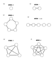
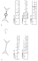
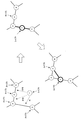
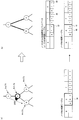
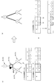
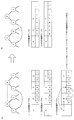
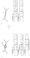
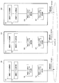
- FIG. 1 (a) is a diagram conceptually showing a part of a network system according to an embodiment of the present invention.
- FIGS. 1 (b) to 1 (g) are respectively for explaining different types of nodes.
- FIG. Each of FIG. 2A to FIG. 2F is a diagram showing the relationship between the number of nodes and the network configuration.
- FIG. 3 is a diagram for explaining node participation rules in a conventional network system.
- FIG. 4 is a diagram for explaining node participation rules in the network system of the present invention.
- FIG. 5A and FIG. 5B are diagrams specifically showing node participation rules in the network system of the present invention.
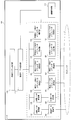
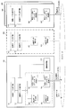
- FIG. 6 is a diagram showing the configuration of the network system and the nodes in the embodiment of the present invention.
- FIG. 7 is a diagram showing an example of the structure of route table information used in the embodiment of the present invention.
- FIG. 8 is a diagram illustrating the relationship between the information stored in the route table and the configuration between nodes.
- FIG. 9A is a diagram showing a general example of a route table used in the embodiment of the present invention
- FIG. 9B is a diagram between nodes corresponding to the route table shown in FIG. It is a figure which shows a structure.
- FIG. 10 is a diagram illustrating an example of the types of event keys used in the embodiment of the present invention.
- FIG. 11 shows an example of node participation.
- FIG. 11A shows a configuration between nodes before the node X participates and a route table of each node.
- FIG. 11B shows a node X participation.
- FIG. 12 is a diagram illustrating a change in the configuration between nodes due to the participation of the node Y.
- FIG. 13 is a block diagram showing a specific configuration of the node in the embodiment of the present invention.
- FIG. 14 is a diagram illustrating a flow of information in the network system when a node participates.
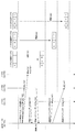
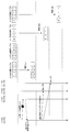
- FIG. 15 is a diagram illustrating a sequence and transition of each route table when a node participates.
- FIG. 16 shows another example of node participation, FIG. 16 (a) shows the configuration between the nodes before the node X participates, and the routing table of each node, and FIG.
- FIG. 16 (b) shows the node A configuration between nodes after X participates and a route table of each node are shown.
- FIG. 17 is a diagram illustrating an example in which a route is added by a periodic route addition event.
- FIG. 17A illustrates a configuration between nodes before a route is added, and FIG. The structure between the nodes after adding is shown.
- FIG. 18 is a diagram showing a flow of information in the network system when a route is added by a periodic route addition event.
- FIG. 19 is a diagram illustrating a sequence when a route is added by a periodic route addition event and transition of each route table.
- FIG. 20 is a diagram for explaining alive monitoring of nodes in the network system.
- FIG. 20 is a diagram for explaining alive monitoring of nodes in the network system.
- FIG. 21 is a flowchart showing the operation of the node during execution of life and death monitoring.
- FIG. 22 is a diagram showing an example of a type 2 node leaving the network.
- FIG. 22A shows a configuration between nodes before the node leaves and a route table of each node.
- b) shows the configuration between the nodes after leaving the node and the route table of each node.
- FIG. 23 is a diagram illustrating an example in which a new route is constructed after a type 2 node in the network leaves, and FIG. 23A illustrates a configuration between nodes and a route of each node before construction of a new route.
- FIG. 23B shows a configuration between nodes after the construction of a new route and a route table of each node.
- FIG. 24 is a diagram showing the flow of information in the network system when a new route is constructed after a type 2 node in the network leaves.
- FIG. 25 is a diagram illustrating a sequence and a transition of each route table when a new route is constructed after a type 2 node in the network leaves.
- FIG. 26 is a diagram illustrating an example in which a type 3i node in the network leaves and a type 2 node first detects the leave.
- FIG. 26A shows the configuration between nodes before leaving the node and the route table of each node
- FIG. 26B shows the configuration between nodes after leaving the node and the route table of each node. Show.
- FIG. 27 is a diagram for explaining detection of node detachment shown in FIG. FIG.
- FIG. 27A shows a state in which the node separation is detected
- FIG. 27B shows a state after the node separation is detected
- FIG. 28 is a diagram for explaining a notification performed after the node is detached as illustrated in FIG.
- FIG. 28A shows a state in which notification is performed after the node leaves
- FIG. 28B shows a state after notification.
- FIG. 29 is a diagram showing the flow of information in the network system when a new route is constructed after a type 3i node in the network leaves.
- FIG. 30 is a diagram showing a sequence and a transition of each route table when a new route is constructed after a type 3i node in the network leaves.
- FIG. 31 is a diagram illustrating an example in which a type 3i node in the network leaves and the type 3 node first detects leave.
- FIG. 31A shows the configuration between nodes before leaving the node and the route table of each node
- FIG. 31B shows the configuration between nodes after leaving the node and the route table of each node.
- FIG. 32 is a diagram for explaining an example of notification that is performed after the node leaves illustrated in FIG. 31.
- FIG. 32A shows a state in which notification is performed after the node leaves
- FIG. 32B shows a state after notification.
- FIG. 33 is a diagram for explaining another example of the notification performed after the node leaving illustrated in FIG. 31.
- FIG. 33A shows a state in which notification is performed after a node leaves
- FIG. 33B shows a state after notification.
- FIG. 34 is a diagram showing an information flow in the network system in another case where a new route is constructed after a type 3i node in the network leaves.
- FIG. 35 is a diagram showing a sequence in another case where a new route is constructed after a type 3i node in the network leaves and the transition of each route table.
- FIG. 36 is a diagram illustrating an example in which a type 3c node leaves the network with two nodes of type 3c and one node of type 3i as connection destinations, and FIG. The configuration between the previous nodes and the route table of each node are shown, and FIG. 36 (b) shows the configuration between the nodes after leaving the node and the route table of each node.
- FIG. 34 is a diagram showing an information flow in the network system in another case where a new route is constructed after a type 3i node in the network leaves.
- FIG. 35 is a diagram showing a sequence in another case where a new route is constructed after a
- FIG. 37 is a diagram showing the return of the node disconnected from the network to the network due to the node detachment shown in FIG. 36
- FIG. 37 (a) shows the state before the occurrence of the detachment
- FIG. 38 is a diagram illustrating an example in which a type 3c node leaves the network with three type 3c nodes as connection destinations, and FIG. 38A illustrates a configuration between nodes before the node leaves.
- FIG. 38B shows a configuration between nodes after the node has left.
- FIG. 39 is a diagram for explaining an example of provisional route creation processing and confirmation processing when node separation shown in FIG. 38 occurs, and FIG. 39A shows provisional route creation processing.
- FIG. 39B is a diagram showing the confirmation process.
- FIG. 40 is a diagram for explaining another example of a temporary route creation process and a confirmation process when the node separation shown in FIG. 38 occurs.
- FIG. 40A is a diagram showing a temporary route creation process
- FIG. 40B is a diagram showing a confirmation process.
- FIG. 41 is a diagram illustrating an example in which a node in the network starts the leaving process itself, and FIG. 41A illustrates a configuration between nodes before leaving the node and a route table of each node. (B) shows the configuration between nodes after the node leaves and the route table of each node.
- FIG. 42 is a diagram showing an information flow in the network system when a node in the network starts the leaving process itself.
- FIG. 43 is a diagram showing a sequence and transition of each route table when a node in the network starts the leaving process itself.
- FIG. 44 is a block diagram illustrating an example of a computer that implements a node according to an
- FIG. 1 (a) is a diagram conceptually showing a part of a network system according to an embodiment of the present invention.
- FIGS. 1 (b) to 1 (g) are respectively for explaining different types of nodes.
- FIG. 1 (b) is a diagram conceptually showing a part of a network system according to an embodiment of the present invention.
- FIGS. 1 (b) to 1 (g) are respectively for explaining different types of nodes.
- FIG. 1 (a) is a diagram conceptually showing a part of a network system according to an embodiment of the present invention.
- FIGS. 1 (b) to 1 (g) are respectively for explaining different types of nodes.
- the node 1 is a computer (hardware device) connected to a network and capable of executing a program, or the like.
- the path 2 is a communication path that connects between the node 1 and the node 1.
- the path 2 has nodes 1 at both ends thereof, and does not include the node 1 in the middle. Further, the route 2 does not branch on the way.
- the type is the type of the node 1 that is distinguished by the number of connected paths 2.
- Fig. 1 (b) shows "Type 0".
- Type 0 is a node with 0 routes.
- FIG. 1C shows “type 1”.
- Type 1 is a node with one path.
- FIG. 1D shows “Type 2”.
- Type 2 is a node with 2 routes.
- FIG. 1E shows “Type 3”.
- Type 3 is a node with 3 routes.
- the “type 3” node is further subdivided into two types, “type 3i” and “type 3c”.
- FIG. 1F shows “type 3i”.
- Type 3i is a type in which a node of type 2 is included in the three nodes connected by each route.
- FIG. 1G shows “type 3c”.
- the type 3c is a type in which a node of type 2 is not included in the three nodes connected by each route.
- FIG. 2A to FIG. 2F is a diagram showing the relationship between the number of nodes and the network configuration.
- FIG. 2A shows a case where the number of routes is 0 (zero). As shown in FIG. 2A, when the number of routes is zero, the node 1 is not yet in the network.
- FIG. 2B shows a case where the number of routes is one.
- the number of routes is one
- nodes 1 exist at both ends of the route 2, and each node 1 is located at the end of the network. Therefore, when the path 2 is disconnected, the node 1 is isolated from the network.
- the state in which the number of paths of all the nodes 1 on the network is one is a state that is not possible except when the number of nodes in the network is two.
- FIG. 2 (c) shows a case where the number of routes is two. As shown in FIG. 2C, if the number of connections of all the nodes 1 in the network is two, the node 1 becomes a part of the ring network. Further, if the node 1 with one connection is included in the network, the node 1 becomes a part of the line network as shown in FIG.
- the line-shaped network shown in FIG. 2 (d) when any route 2 is disconnected, the line-shaped network shown in FIG. 2 (d) is obtained. Further, in the line-shaped network shown in FIG. 2D, when any route is disconnected, the network network is divided into two.
- FIG. 2 (e) shows a case where the number of routes is three.
- the node 1 is a part of the mesh network. If the number of connections of all the nodes 1 in the network is three, the mesh network is maintained regardless of which path 2 is disconnected.
- FIG. 2 (f) shows a case where the number of routes is four.
- the node 1 becomes a part of the mesh network as in the case where the number of paths is three.
- the number of routes 2 is further increased as compared with the case where the number of routes is three.
- each of the three routes of a specific node may be expressed as route (1), route (2), and route (3).
- FIG. 3 is a diagram for explaining node participation rules in a conventional network system.
- FIG. 4 is a diagram for explaining node participation rules in the network system of the present invention.
- FIG. 5A and FIG. 5B are diagrams specifically showing node participation rules in the network system of the present invention.
- a to K and X represent nodes.
- a node when a node participates in a network, a specific node in the P2P network is uniquely specified. For example, a participant generally designates the IP address of a particular node and joins his node to the P2P network.
- the present invention since the number of routes of all nodes is basically set to three, the node cannot participate in a specific node. Yes. For this reason, as shown in FIG. 4, the present invention employs the concept of joining nodes as routes. In the present invention, as shown in FIGS. 5A and 5B, participation rules are the following two points.
- rule 1 specifies that node 1 must be placed between one path 2. Further, as shown in FIG. 5B, rule 2 specifies that the nodes 1 located at both ends of the path 2 must be of type 3.
- FIG. 6 is a diagram showing the configuration of the network system and the nodes in the embodiment of the present invention.
- a network system 500 has a network including a plurality of nodes 100 to 400.
- the number of nodes shown is four, but the number of nodes is not limited in the present embodiment.
- each node has the same configuration, and the node 100 will be described as an example.
- the node 100 includes a route table storage unit 114 that stores route table information, and a route table operation unit 113 that can rewrite the contents of the route table information.
- the route table information is information for specifying the connection destination of the node 100 and further limiting the number of connection destinations. Specifically, in the node 100, the route table information first includes a self-node route table that identifies the nodes 200 to 400 directly connected to the node 100. The route table information also includes an other node route table that identifies a node connected to each of the other nodes 200 to 400 directly connected to the node 100.
- the route table operation unit 113 is configured so that the node 100 directly joins the network, the node directly connected to the node 100 joins the network, and the node directly connected to the node 100 leaves the network. In this case, the own node route table and the other node route table in the node 100 are updated. Thereby, a new route in the network system 500 is constructed.
- the number of nodes to which each node is connected is limited, and when participation or withdrawal occurs in the network, a new route is constructed only by updating the route table information. Is done. For this reason, according to the present embodiment, it is possible to autonomously construct a communication path both in joining and leaving a node while suppressing an increase in processing load in the network.
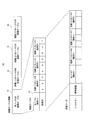
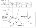
- FIG. 7 is a diagram showing an example of the structure of route table information used in the embodiment of the present invention.
- FIG. 8 is a diagram illustrating the relationship between the information stored in the route table and the configuration between nodes.
- the route table information 10 is connected to the own node route table 11 for identifying the node directly connected to the own node A and the other nodes B to D directly connected to the own node.
- other node route tables 12 to 14 for identifying the current node.
- the middle part of FIG. 7 and FIG. 8 show the detailed structure of the own node route table 11.
- the own node route table 11 includes a value (identifier) that can uniquely identify the own node A and each of the nodes B to C connected to the route (1) to the route (3), for example, an IP address, etc. Is registered. Further, in the examples of FIGS. 7 and 8, for the nodes B to C connected to the routes (1) to (3), the identifiers of the nodes connected to the routes (1) to (3) are also shown. It is registered.
- a, b, and A registered in relation to the node B connected to the route (1) are connected to the route (1) to the route (3) of this node B.
- the identifier of each node is shown.
- b, A, and c registered in relation to the node C connected to the route (2) are identifiers of the nodes connected to the route (1) to the route (3) of the node C.
- A, e, and f registered in relation to the node D connected to the route (3) are identifiers of the nodes connected to the route (1) to the route (3) of the node D. Show.
- transmission data used for data transmission between nodes is shown.
- the transmission data includes information of the own node route table, an event key, and failure information. Details of the transmission data will be described later.
- the route table information has two features. One is that the table length is fixed because the number of paths of each node is limited to three. Second, it is possible to manage not only information (route information) related to the route of the own node but also route information of each of the three routes connected to the own node.
- the order of the routes that is, whether it is route (1), route (2), or route (3) has no meaning.
- FIG. 9A is a diagram showing a general example of a route table used in the embodiment of the present invention
- FIG. 9B is a diagram between nodes corresponding to the route table shown in FIG. It is a figure which shows a structure.
- the own node is the node A
- the path table shown in FIG. 9A shows the configuration of the nodes within the range managed by the node A.
- “alphabet” indicates a value (identifier) for identifying a node
- “?” Indicates that there is some value.
- a blank column indicates that no value exists.
- the information stored in the route table shown in FIG. 9A is included in the transmission data in the data transmission between nodes as shown in the lower part of FIG. For this reason, the information stored in the route table is shared between the nodes. As shown in FIG. 7, the transmission data includes an event key and failure information.
- FIG. 10 is a diagram illustrating an example of the types of event keys used in the embodiment of the present invention.
- FIG. 11 shows an example of node participation.
- FIG. 11A shows a configuration between nodes before the node X participates and a route table of each node
- FIG. 11B shows a configuration between nodes after the node X participates and each node. Shows the routing table.
- node X is made to participate here, node X will participate in one route in the network.
- one of the three routes becomes a route connected to the newly joined node X. It should be noted that no route change occurs in other nodes in the network.
- connection destination node A in the route table of node A, only the connection destination node B is changed to node X, and in the node B route table, the connection destination node A is a node. It only changes to X.
- the participating node X is always connected to two paths, and thus becomes a type 2 node.
- the node X participates in a network composed of type 3c nodes. At this time, the number of paths connected to nodes other than the node X is all three. Therefore, the node X is in a state where the number of routes cannot be increased further.
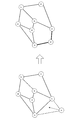
- FIG. 12 is a diagram illustrating a change in the configuration between nodes due to the participation of the node Y.
- both ends of the path used for joining node Y must be type 3 nodes, so node Y should participate in the path of type 2 nodes.
- connection destination routes is changed at the nodes at both ends of the route to which node Y is joined as described above, and the joined node Y has two routes, type 2 (See the central diagram in FIG. 12).
- the node X that joined earlier is also of type 2 (see FIG. 11B)
- the node X establishes a route with the newly joined node Y
- both the nodes X and Y are of type 3 Become a node. That is, a new path is established between the newly joined node Y and the previously joined node X (see the lower diagram of FIG. 12).
- nodes When nodes are joined by the method described above, all the nodes in the network are type 3 or only one node is type 2 and the other nodes are type 3. One of them. For this reason, the network configuration can be simplified.
- FIG. 13 is a block diagram showing a specific configuration of the node in the embodiment of the present invention.
- FIG. 13 only one node 100 configuring the network system 500 (see FIG. 6) is illustrated. It is assumed that there are a plurality of nodes having the same configuration as the node 100 in the network.
- the node 100 has the following configuration in addition to the route table operation unit 113 and the route table storage unit 114 shown in FIG. Specifically, the node 100 includes a regular data transmission unit 101, a regular data creation unit 102, a regular data reception unit 103, and a regular data analysis unit 104 in order to monitor the state of each node.
- the node 100 triggers the update of the route information to the specific node, so that the event data transmitting unit 105 for the specific node, the event data creating unit 106 for the specific node, the event data receiving unit 107 for the specific node, and the specific A node event data analysis unit 108.
- the node 100 triggers an update of a route change that is not conscious of a specific node when the node joins, etc., so that the event data transmission unit 109 for unspecified nodes, the event data creation unit 110 for unspecified nodes, and the unspecified An event data reception unit 111 for nodes and an event data analysis unit 112 for unspecified nodes are provided.
- the route table storage unit 114 stores data necessary for autonomously constructing a route between nodes, that is, route table information (see FIG. 2). .
- the route table operation unit 113 performs an operation on the route table information based on each event information.
- the node 100 also includes a failure processing unit 115 in order to cope with a failure when a failure occurs in each component unit due to communication processing or the like.
- the failure processing unit 115 performs failure processing based on failure information in each unit from the regular data transmission unit 101 to the event data analysis unit 112 for unspecified nodes.
- the regular data creation unit 102 acquires the route table information held by the route table storage unit 114 via the route table operation unit 113 during normal operation. Then, the periodic data creation unit 102 periodically transmits the acquired route table of the own node to the nodes of each route by the periodic data transmission unit 101.
- the regular data receiving unit 103 receives the route table from another node.
- the periodic data analysis unit 104 analyzes the contents of the received route table of the other node.
- the route table operation unit 113 updates the route table information held by the route table storage unit 114 when the route table information needs to be updated.
- the case where it is necessary to update the routing table information is when some kind of node state change has occurred.
- the periodic data analysis unit 104 determines a transmission event based on the result of the data analysis, and sends the route table information of the own node to the event data creation unit for specific node 106 or the event data creation unit for unspecified node 110. Make the event data included. Then, the periodic data analysis unit 104 transmits the created event data to the event data transmission unit 105 for specific nodes or the event data transmission unit 109 for unspecified nodes.
- event data transmitted from other nodes is received by the event data receiving unit 107 for specific nodes or the event data receiving unit 111 for unspecified nodes. Then, the event data analysis unit for specific node 108 or the event data analysis unit 112 for unspecified nodes analyzes the received event data.
- event data needs to be further transmitted as a result of the analysis, event data is transmitted in the same manner. If the route table needs to be updated, the route table operation unit 113 updates the route table information stored in the route table storage unit 114.
- FIG. 14 is a diagram illustrating a flow of information in the network system when a node participates.
- FIG. 15 is a diagram illustrating a sequence and transition of each route table when a node participates.
- FIG. 14 shows only the configuration necessary for the explanation of FIG. 15 among the configurations of the node 100 shown in FIG. Also, in the node 200, only the configuration necessary for the description of FIG. 15 is shown. In addition, in the functional blocks of the node 100 and the node 200, the functional blocks having the same last two digits are the same. Further, in FIG. 15, the node 100 is expressed as a node X, and the node 200 is expressed as a node A, a node B, and a node C.
- nodes A, B, and C there are a plurality of nodes (nodes A, B, and C) having the same configuration as the node 200 in the network, and each node has information having the same structure as the route table information shown in FIG. It is assumed that it is held in the route table storage unit 214. On the other hand, it is assumed that the node 100 (node X) participating in the network stores only its own node information and not other node information in the route table information of the route table storage unit 114.
- the event data creation unit 110 for unspecified nodes in the node X via the route table operation unit 113, has its own node route table (see FIG. 15). 7).
- the event data creation unit 110 for unspecified nodes uses the acquired route table, stores the node participation event key in the event key, and creates node participation event data (transmission data: see FIG. 7).
- the event data creation unit 110 for unspecified nodes transmits node participation event data from the event data transmission unit for unspecified nodes into the network (step A1).
- the event data receiving unit 211 for unspecified nodes receives the node participation event data (step A2). Then, the unspecified node event data analysis unit 212 analyzes the event key of the event data received from the unspecified node event data reception unit 211. If the event data analysis unit 212 for unspecified nodes determines that the event is a node participation event from the event key in the data, the event data analysis unit 212 acquires the route table of the own node from the route table storage unit 214 via the route table operation unit 213. .
- the event data analysis unit 212 for the unspecified node determines the type of the own node, and if it is not type 3 (if it is type 2), it determines that participation is not permitted and performs the processing without doing anything. End (Node C).
- the event data analysis unit 212 for the unspecified node accepts participation, and therefore the event data creation unit 206 for the specific node sends the route table of the own node. give. Furthermore, the event data analysis unit 212 for unspecified nodes also passes the route table of the node X included in the node participation event data received in step A2 to the event data creation unit 206 for specific nodes.
- the event data creation unit 206 for a specific node stores the candidate node event key in the event key and creates candidate node event data (transmission data) based on the route table of the own node (nodes A and B). To do. Then, the event data creation unit 206 for the specific node transmits candidate node event data from the event data transmission unit 205 for the specific node with the node X that is the transmission source of the node participation event data received in step A2 as the transmission destination node. (Step A3).
- the event data receiving unit for specific node 107 receives candidate node event data (step A4), and sends the received data to the event data analyzing unit for specific node 108.
- the event data analyzing unit for specific node 108 determines that the event is a candidate node event from the event key in the received data. Further, the event data analysis unit for specific node 108 receives candidate node events from two different nodes A and B, and therefore checks whether the same route exists from the route tables of the nodes A and B. As a result of the confirmation, if the presence of the same route cannot be confirmed, the node X further receives a candidate node event and confirms the route.
- the route of node A (1) and the route of node B (1) are the same route. Therefore, the event data analysis unit for specific node 108 finds the same route based on the route table from a plurality of nodes. Then, the event data analysis unit 108 for a specific node creates a route table with the nodes A and B that are both ends of the node X as connection destinations, and automatically stores the route table in the route table storage unit 114 via the route table operation unit 113. The node route table is updated (step A5).
- the event data analysis unit for specific node 108 passes the updated own node route table to the event data creation unit 106 for specific node.
- the event data creation unit for specific node 106 stores the route determination event in the event key, and creates route determination event data based on the updated route table.
- the event data creation unit for specific node 106 transmits the route determination event data from the event data transmission unit 105 for the specific node using each connection destination as the transmission destination of the route determination event data (step A6).
- the event data receiving unit 207 for specific nodes receives the route determination event data (step A7). Then, the event data analysis unit 208 for a specific node confirms that the event is a route determination event from the event key in the received data. As a result, the event data analysis unit 208 for the specific node updates the route table in the route table storage unit 214 via the route table operation unit 213 based on the route table in the received data (step A8).
- any of the two other connection destinations (total of four nodes) of each of the two nodes A and B having the same route. May be a type 2 node.
- three nodes including type 2 nodes are preferably connected to the participating node X. Note that there are four nodes in total because there are three paths per node, and one of them is the same, so there are two other nodes and two corresponding nodes.
- FIG. 16 shows another example of node participation.
- FIG. 16A shows a configuration between nodes before the node X participates and a route table of each node
- FIG. 16B shows a configuration between the nodes after the node X participates and each node. The node routing table is shown.
- the path 3 between the node A and the node B is the same path.
- the node A includes a path 4 with the node C and a path 5 with the node D.
- the node B there are a route 6 to the node E and a route 7 to the node F.
- the participating node X is connected to node C in addition to node A and node B located at both ends thereof. Connected.
- the portion surrounded by a thick frame is automatically determined and updated according to the rule of node participation as shown in FIG.
- FIG. 17 is a diagram illustrating an example in which a route is added by a periodic route addition event.
- FIG. 17A shows the configuration between the nodes before the addition of the route
- FIG. 17B shows the configuration between the nodes after the addition of the route.
- each node becomes a type 3 node by creating a route between the nodes.
- type 2 node A periodically transmits a route addition event to other nodes to search for another type 2 node. . Then, as shown in FIG. 17B, when another type of node is found, the node A creates a route with the node.
- FIG. 18 is a diagram showing a flow of information in the network system when a route is added by a periodic route addition event.
- FIG. 19 is a diagram illustrating a sequence when a route is added by a periodic route addition event and transition of each route table.
- FIG. 18 shows only the configuration necessary for the explanation of FIG. 19 among the configurations of the node 100 shown in FIG. Also, in the node 200, only the configuration necessary for the description of FIG. 19 is shown. In addition, in the functional blocks of the node 100 and the node 200, the functional blocks having the same last two digits are the same. Further, in FIG. 19, the node 100 is expressed as a node A, and the node 200 is expressed as a node B and a node C.
- the event data creation unit 110 for the unspecified node of the type 2 node A via the route table operation unit 113, the route table of its own node in the route table storage unit 114 (FIG. 7). Reference).
- the event data creation unit 110 for unspecified nodes uses the acquired route table, stores the route addition event key in the event key, and creates route addition event data.
- the unspecified node event data creation unit 110 periodically transmits the created route addition event data from the unspecified node event data transmission unit 109 into the network (step B1).
- the nodes B and C in the network receive the route addition event data by the event data receiving unit 211 for unspecified nodes (step B2). Then, the event data analyzing unit 212 for unspecified nodes receives data from the event data receiving unit 211 for unspecified nodes and analyzes it. Further, the event data analysis unit 212 for unspecified nodes determines that the event is a route addition event based on the event key in the data. Next, the event data analysis unit 212 for unspecified nodes acquires the route table (see FIG. 7) of the own node from the route table storage unit 214 via the route table operation unit 213.
- the event data analysis unit 212 for the unspecified node determines the type of the own node, and if it is not type 2 (type 3), does nothing and ends the process (node C).
- the event data analysis unit 212 for the unspecified node passes the route table of the own node to the event data creation unit 206 for the specific node. Furthermore, the event data analysis unit 212 for unspecified nodes also passes the route table for the node A included in the route addition event data received in step B2 to the event data creation unit 206 for specific nodes.
- the event data creation unit 206 for a specific node stores the candidate node event key in the event key and creates candidate node event data (transmission data) based on the route table of the own node (node B). Then, the event data creation unit 206 for the specific node transmits candidate node event data from the event data transmission unit 205 for the specific node with the node A that is the transmission source of the route addition event data received in step B2 as the transmission destination ( Step B3).
- the event data reception unit 107 for specific node receives the candidate node event (step B4), and sends the received data to the event data analysis unit 108 for specific node.
- the event data analysis unit for specific node 108 determines that the event is a candidate node event from the event key in the received data. In addition, since the event data analysis unit 108 for the specific node receives the route table of the candidate node B, it confirms that the candidate node B is type 2 from now on.
- the event data analysis unit for specific node 108 creates a route table with the candidate node B as a connection destination, and passes the route table via the route table operation unit 113.
- the route table in the table storage unit 114 is updated (step B5).
- the event data analysis unit for specific node 108 passes the updated route table to the event data creation unit 106 for specific node.
- the event data creation unit for specific node 106 stores the route determination event in the event key, and creates route determination event data based on the updated route table.
- the event data creation unit for specific node 106 transmits the route determination event data from the event data transmission unit 105 for the specific node using the connection destination as the transmission destination of the route determination event data (step B6).
- the event data receiving unit 207 for the specific node receives the route determination event data (step B7). Then, the event data analysis unit 208 for a specific node confirms that the event is a route determination event from the event key in the received data. Thereby, the event data analysis unit 208 for the specific node updates the route table in the route table storage unit 214 via the route table operation unit 213 based on the route table in the received data (step B8).
- a new path is constructed between the node A and the node B as shown in FIG.
- FIG. 20 is a diagram for explaining alive monitoring of nodes in the network system.
- FIG. 21 is a flowchart showing the operation of the node during execution of life and death monitoring.
- node A is connected to node B, node C, and node D.
- the node A periodically transmits data (periodic data) to each of the connection destination nodes B to D through each route, thereby monitoring the life and death of these connection destination nodes.
- each node constituting the network monitors only nodes directly connected by a route, that is, only adjacent nodes. Therefore, even if the number of nodes in the network increases, the number of nodes monitored by a certain node is limited to a maximum of three nodes. For this reason, the data amount of the periodic data for monitoring the node flowing through the network is suppressed. In addition, transmission of regular data by each node is performed in an unlinked manner.
- Each node determines that an abnormality has occurred in a specific node when there is an abnormality in the transmission of the periodic data to the specific node and when there is a delay in the reception of the periodic data from the specific node. To do. Each node also determines that there is an abnormality in the corresponding node even if there is an abnormality in the value of the route table in the transmission data between the nodes including the event data.
- the failure processing unit 115 first determines whether or not a failure has occurred in the destination node (step C1). Specifically, the failure processing unit 115, when there is a transmission abnormality in the regular data transmission unit 101 and when there is a transmission abnormality in the event data transmission unit 105 for a specific node, the destination node (data destination It is determined that a failure has occurred in the node.
- step C1 the failure processing unit 115 executes step C2 if no failure has occurred in the transmission destination node, and performs step C3 if a failure has occurred in the transmission destination node. Execute.
- the failure processing unit 115 determines whether a failure has occurred in the destination node. Specifically, the failure processing unit 115, when the regular data analysis unit 104 is not notified of the reception data from the regular data reception unit 103 for a certain period of time, notifies the reception destination node (node that is the data transmission source). Determine that a failure has occurred.
- the failure processing unit 115 executes Step C1 again if the result of the determination in Step C2 is that no failure has occurred in the destination node, and Step C3 if a failure has occurred in the destination node. Execute.
- the failure processing unit 115 executes a node leaving process. Therefore, the node leaves the network. Therefore, in step C3, a new route generation process is executed by the node 100 that detects the failure.
- the node that has detected the failure earliest may execute Step C3 after the node in which the failure has occurred.
- a node leaves the network.
- One is a case where the node in which the failure has occurred cannot notify the other node of its own departure due to the failure, and the other node detects an abnormality based on a communication failure or the like and determines that the node has left.
- the other is a case where the leaving node notifies the other nodes of the network before leaving and leaves the network.
- the rules for joining nodes to the network are clear, so that the pattern of node connection combinations when a node leaves is fixed. For this reason, the difference between the former and the latter relating to leaving the node is only whether the node remaining on the network without leaving creates a new route or the node scheduled to leave creates a new route.
- the former will be described.
- FIG. 22 is a diagram illustrating an example in which a type 2 node in the network leaves.
- FIG. 22A shows the configuration between nodes before leaving the node and the route table of each node
- FIG. 22B shows the configuration between nodes after leaving the node and the route table of each node. Show.
- FIG. 23 is a diagram showing an example in which a new route is constructed after a type 2 node in the network leaves.
- FIG. 23A shows a configuration between nodes before construction of a new route and a route table of each node
- FIG. 23B shows a configuration between nodes after construction of a new route and a route table of each node. It shows.
- the node A When the node A detects the detachment of the node X, the node A specifies that the node X is type 2 and that the connection destination node other than the node A is the node B based on the route information 21 of the route table.
- the node A transfers the route information 21 of the node X in the route table to the route information 20 of the node B in the route table of the node X (see FIG. 22B).
- a value (identifier) for identifying the node X that has left is still left in the route information 22 of the node B after the transfer. Therefore, the node A further transfers the information of the node X to a value for identifying the node A which is the node A (see FIG. 22B). Thereby, the route table of the node A is established with the information of the new route.
- the node A transmits connection request event data to the new connection destination node B.
- the node B compares the route information of each node in the route table of the own node B with the route information 24 of the own node in the route table included in the connection request event data. In this case, the node B determines that the node X does not exist at the connection destination and has changed to the node A.
- the node B replaces the route information 23 of the node X (see FIG. 23A) with the route information 25 of the node A in the route table of the own node. At this time, the node B writes the value of the connection request event data column 26 into the blank field 28 in the route information 25, and writes the value of the connection request event data column 27 into the blank field 29 in the route information 25.
- FIG. 24 is a diagram showing the flow of information in the network system when a new route is constructed after a type 2 node in the network leaves.
- FIG. 25 is a diagram illustrating a sequence and a transition of each route table when a new route is constructed after a type 2 node in the network leaves.
- FIG. 24 shows only the configuration necessary for the description of FIG. 25 among the configurations of the node 100 shown in FIG. Also, in the nodes 200 and 300, only the configuration necessary for the description of FIG. 25 is shown. Further, in each functional block of each of the nodes 100 to 300, it means that functional blocks having the same last two digits are the same. Further, in FIG. 25, the node 100 is represented as a node A, the node 200 is represented as a node X, and the node 300 is represented as a node B.
- the regular data transmission unit 101 detects a failure based on the transmission error (step D2), and notifies the failure processing unit 115 of the abnormality information regarding the detected abnormality.
- the failure processing unit 115 acquires the route table of the node X from the route table information (see FIG. 7) in the route table storage unit 114 via the route table operation unit 113. Further, the failure processing unit 115 identifies Node B as a new connection destination from the contents of the acquired route table.
- the failure processing unit 115 updates the route table of the node A via the route table operation unit 113 (step D3), and passes the updated route table of the node A to the event data creation unit 106 for specific node. .
- the specific node-oriented event data creation unit 106 creates connection request event data using the received updated route table of the node A.
- the event data creation unit 106 for the specific node stores the connection request event in the event key (see FIG. 7), and further identifies the information on the failed node (failed node) in the failed information (see FIG. 7). Value).
- the event data creation unit for specific node 106 transmits the created connection request event data from the event data transmission unit for specific node 105 to the node B (step D4).
- the event data receiving unit 307 for the specific node receives the connection request event data (step D5).
- the event data analysis unit 308 for specific nodes receives the connection request event data from the event data reception unit 307 for specific nodes and analyzes it.
- the event data analysis unit 308 for the specific node determines that it is a connection request event from the event key in the data. Therefore, the event data analysis unit 308 for the specific node updates the route table of the node B stored in the route table storage unit 314 via the route table operation unit 313 (step D6).
- the node B can transmit the periodic data to the node X (step D7) before receiving the connection request event data, and can detect a failure in the node X based on the transmission error. (Step D8). However, the node B receives a notification that a failure has occurred in the node X based on the failure information in the connection request event data from the node A. Therefore, in this case, the node B does not perform any processing for failure detection.
- step D8 a transmission error (step D8) has occurred before the connection request event data is received at node B (before step D4)
- node A also has node A
- the route update process is performed in the same manner as described above, but since the update results are the same, there is no particular problem.
- type 3 includes type 3 i including type 2 at the connection destination node and type 3 c not including type 2.
- type 3i includes type 3 i including type 2 at the connection destination node and type 3 c not including type 2.
- the leaving of a type 3i node will be described.
- FIG. 26 is a diagram illustrating an example in which a type 3i node in the network leaves and a type 2 node first detects the leave.
- FIG. 26A shows the configuration between nodes before leaving the node and the route table of each node
- FIG. 26B shows the configuration between nodes after leaving the node and the route table of each node. Show.
- FIG. 27 is a diagram for explaining detection of node detachment shown in FIG.
- FIG. 27A shows a state in which the node separation is detected
- FIG. 27B shows a state after the node separation is detected.
- FIG. 28 is a diagram for explaining a notification that is performed after the node shown in FIG. FIG. 28A shows a state in which notification is performed after the node leaves, and FIG. 28B shows a state after notification.
- node X leaves, it is the three nodes of node A, node B, and node C that are on the route, but these three nodes are not equivalent.
- the node that detected the detachment is type 2 and type 3, but the method is different in each case.
- a case will be described in which the node that first detects the departure is a type 2 node A.
- the node 2 of type 2 detects the departure of the node X, from the route table of the node X in the own node A, the node X is type 3i, It is specified that the connection destination nodes other than the own node are the node B and the node C.
- the node A replaces the route information 30 of the node B in the route table of the node X with the position of the route information 31 of the leaving node X in the route table of the own node A. Move to. Further, the node A transfers the route information 32 of the node C in the route table of the node X to the free area 33 of the route table of the own node A.
- the route information columns 34 and 35 of the node B and the node C include the detached node X.
- Information (value for identifying the node X) remains. For this reason, the node A replaces the information of the node X in the columns 34 and 35 with the information of the node A that is its own node.
- the new route information is established in the node A route table. Therefore, as illustrated in FIGS. 28A and 28B, the node A transmits connection request event data to the nodes B and C that are the connection destinations on the new route.
- the connection destination of the route of the own node has changed from the node X to the node A, and the connection request event data is sent from the node A. Change the route.
- the node B when the node B receives the connection request event data, the node B in the route table of the own node B and the received connection request event are received. The route information 37 of the own node in the route table in the data is compared. Then, the node B determines that the node X does not exist at the connection destination and the node X has changed to the node A.
- the node B replaces the route information 36 of the node X with the route information of the node A in the route table of the own node. At this time, the node B writes the value of the connection request event data field 38 in the blank field 40 of the path information of the node A in FIG. The value in the request event data column 39 is written.
- FIG. 29 is a diagram showing the flow of information in the network system when a new route is constructed after a type 3i node in the network leaves.
- FIG. 30 is a diagram showing a sequence and a transition of each route table when a new route is constructed after a type 3i node in the network leaves.
- FIG. 30 29 only the configuration necessary for the explanation of FIG. 30 is shown among the configurations of the node 100 shown in FIG. Also, in the nodes 200 to 400, only the configuration necessary for the description of FIG. 30 is shown. Further, in each functional block of each of the nodes 100 to 400, it means that functional blocks having the same last two digits are the same. Further, in FIG. 30, the node 100 is expressed as a node A, the node 200 is expressed as a node X, the node 300 is expressed as a node B, and the node 400 is expressed as a node C.
- Node A is a type 2 node. Then, the node A transmits the regular data created by the regular data creation unit 102 from the regular data transmission unit 101 to the node X (step E1).
- the regular data transmission unit 101 detects a failure based on the transmission error (step E2), and notifies the failure processing unit 115 of the abnormality information regarding the detected abnormality.
- the failure processing unit 115 acquires the route table of the node X from the route table information (see FIG. 7) in the route table storage unit 114 via the route table operation unit 113. Further, the failure processing unit 115 determines that the new connection destination is the node B and the node C based on the acquired contents of the route table.
- the failure processing unit 115 updates the route table of the node A (step E3), and passes the updated route table of the node A to the event data creation unit 106 for the specific node.
- the specific node-oriented event data creation unit 106 creates connection request event data using the received updated route table of the node A.
- the event data creation unit 106 for the specific node stores the connection request event in the event key (see FIG. 7), and further identifies the information on the failed node (failed node) in the failed information (see FIG. 7). Value).
- the specific node event data creation unit 106 transmits the created connection request event data from the specific node event data transmission unit 105 to the node B and the node C (step E4).
- the event data receiving unit 307 for the specific node receives the connection request event data (step E5).
- the event data analysis unit 308 for specific nodes receives the connection request event data from the event data reception unit 307 for specific nodes and analyzes it.
- the event data analysis unit 308 for the specific node determines that it is a connection request event from the event key in the data. Therefore, the event data analysis unit 308 for the specific node updates the node B route table stored in the route table storage unit 314 via the route table operation unit 313 (step E6).
- the reception process (step E7) and the update process (step E8) are executed, and the route table of the node C is updated.
- the route table of the node C is updated.
- FIG. 31 is a diagram illustrating an example in which a type 3i node in the network leaves and the type 3 node first detects the leave.
- FIG. 31A shows the configuration between nodes before leaving the node and the route table of each node
- FIG. 31B shows the configuration between nodes after leaving the node and the route table of each node. Show.
- FIG. 32 is a diagram for explaining an example of notification that is performed after the node has left the node shown in FIG.
- FIG. 32A shows a state in which notification is performed after the node leaves
- FIG. 32B shows a state after notification.
- FIG. 33 is a diagram for explaining another example of the notification that is performed after the node leaves shown in FIG.
- FIG. 33A shows a state in which notification is performed after a node leaves
- FIG. 33B shows a state after notification.
- the node X is of type 3i from the route table of the node X in the own node B. It is specified that the connection destination nodes other than the own node are the node A and the node C.
- the node B transfers the route information 50 of the node A (type 2) in the route table of the node X to the position of the route information 51 of the leaving node X in the route table of the own node.
- the route information column 52 of the node A contains the information (node X of the detached node X) as shown in FIG. Value to identify) remains. Therefore, the node B replaces the information of the detached node X in the column 52 with the information of the node B that is its own node.
- the node A is of type 2, there is an empty route, and the route information column 53 of the node A is blank. For this reason, the node B stores information on the node C, which is the remaining node connected to the node X, in the column 53. As a result, the new route information is established in the route table of the node B.
- the node B transmits connection request event data to the node A and the node C which are new connection destinations.
- node A when node A receives connection request event data from node B, the route information of each node in the route table of its own node A and the received connection request The route information 58 of the own node in the route table in the event data is compared. Then, the node A determines that the node X does not exist in the connection destination, and the node X is changed to the node B that is the transmission source of the connection request event data. Further, at this time, the node B also determines that the node C is added to the connection destination.
- the node A replaces the route information 56 of the node X with the route information of the node B in the route table of the own node A. Subsequently, the node A acquires the route information of the node C as a new connection destination from the route information 55 of the node C in the route table of the node X, and replaces this with the free route information 57 (4 in FIG. 31). ). At that time, the node 59 information (value for identifying the node X) remains in the field 59 of the path information 55 of the node C. Therefore, the node A replaces the information of the node X in the column 59 with the information of the node A that is the own node.
- the new route information is established in the node A route table.
- node C when node C receives connection request event data from node B, it receives the path information of each node in the path table of its own node C, and The route information 62 of the own node in the route table in the connection request event data is compared. Since no path exists between the node C and the node B, the node C determines that the path information of the node C does not exist in the received connection request event data.
- the node C confirms whether or not the information of the node C exists in the received connection request event data, and specifies that the node A has a route with the node C (route). Information 62 column 63).
- connection request event data transmitted from the node B stores information indicating that a failure has occurred in the node X as failure information. Therefore, the node C compares the route information 61 of the node X in the route table of the node C with the route information 60 of the node A in the route table of the node X. Then, the node C determines that the node A is a type 2 node, changes from the node X to the node B in the path of the node A, and further adds the node C.
- the node C replaces the route information 61 of the node X in the route table of its own node with the route information 62 of the node A in the received connection request event data.
- the new route information is established in the node C route table.
- FIG. 34 is a diagram showing an information flow in the network system in another case where a new route is constructed after a type 3i node in the network leaves.
- FIG. 35 is a diagram showing a sequence in another case where a new route is constructed after a type 3i node in the network leaves and the transition of each route table.
- the node 100 is expressed as a node B
- the node 200 is expressed as a node X
- the node 300 is expressed as a node A
- the node 400 is expressed as a node C.
- Node B is a type 3 node. Then, the node B transmits the regular data created by the regular data creation unit 102 from the regular data transmission unit 101 to the node X (step F1).
- the regular data transmission unit 101 detects a failure based on the transmission error (step F2), and notifies the failure processing unit 115 of the abnormality information about the detected abnormality.
- the failure processing unit 115 acquires the route table of the node X from the route table information (see FIG. 7) in the route table storage unit 114 via the route table operation unit 113. Further, the failure processing unit 115 determines that the new connection destination is the node A from the contents of the acquired route table.
- the node A is a type 2 node
- the node C is a type 3 node.
- the failure processing unit 115 updates the route table of the node B (step F3), and passes the updated route table of the node B to the event data creation unit 106 for the specific node.
- the specific node-oriented event data creation unit 106 creates connection request event data using the received updated node B route table.
- the event data creation unit 106 for the specific node stores the connection request event in the event key (see FIG. 7), and further identifies the information on the failed node (failed node) in the failed information (see FIG. 7). Value).
- the specific node data creation unit 106 transmits the created connection request event data from the specific node event data transmission unit 105 to the node A and the node C (step F4).
- the event data receiving unit 307 for the specific node receives the connection request event data (step F5).
- the event data analysis unit 308 for specific nodes receives the connection request event data from the event data reception unit 307 for specific nodes and analyzes it.
- the event data analysis unit 308 for the specific node determines that it is a connection request event from the event key in the data. Therefore, the event data analysis unit 308 for the specific node updates the route table of the node A stored in the route table storage unit 314 via the route table operation unit 313 (Step F6).
- the reception process (step F7) and the update process (step F8) are executed, and the route table of the node C is updated.
- the route table of the node C is updated.
- FIG. FIG. 36 is a diagram illustrating an example in which a type 3c node leaves the network with two type 3c nodes and one type 3i node as connection destinations.
- FIG. 36A shows the configuration between nodes before leaving the node and the route table of each node.
- FIG. 36B shows the configuration between nodes after leaving the node and the route table of each node. Show.
- connection destinations are type 3 nodes. Specifically, node A and node C, which are connection destinations, are type 3c, and node B is type 3i. Therefore, when this type 3c node X leaves the network, as shown in FIG. 36B, the node A is disconnected from the network, and the remaining nodes B and C construct a new path between them.
- the node connected to the node A may be connected to the node B or the node C via some nodes, but the node A cannot recognize it and needs to recognize it. Nor.
- FIG. 37 is a diagram illustrating the return of the node disconnected from the network to the network due to the departure of the node illustrated in FIG.
- FIG. 37A shows a state before the occurrence of the departure
- FIG. 37B shows a state where the node has returned to the network after the occurrence of the departure.
- node A node B, and node C, which are connection destinations of the node X to leave, consider these further connection destination nodes.
- the node B is a type 3i including a type 2 node as a connection destination.
- Node X When Node X leaves, it is Node A, Node B, and Node C that are connected to Node X, but these three nodes do not know the node type other than its own node. Therefore, when the node A, node B, and node C detect the departure of the node X, if the node itself is not type 3i (node A, node C), the process of creating a new route is not immediately performed, and the standby state It becomes. On the other hand, when the node A, the node B, and the node C are of type 3i, a new route is established between the node A and one of the remaining two nodes.
- FIG. 38 is a diagram illustrating an example in which a type 3c node leaves the network with three type 3c nodes as connection destinations, and FIG. 38A illustrates a configuration between nodes before the node leaves. FIG. 38B shows a configuration between nodes after the node has left.
- a temporary route is created by any two nodes among the three nodes that have become type 2. Thereafter, it is confirmed whether or not a route that replaces the created temporary route exists, and if it exists, the temporary route is removed. This confirmation process will be described below with reference to FIGS. 39 and 40.
- FIG. 39 is a diagram for explaining an example of a temporary route creation process and a confirmation process when the node separation shown in FIG. 38 occurs.
- FIG. 39A is a diagram showing a state during the execution of the temporary route creation process and the confirmation process
- FIG. 39B is a diagram showing the state after the process is completed.
- a temporary route is created between the node A and the node B.
- the node A and the node B confirm whether or not there is a common connection destination node by using the respective route tables.
- the node D exists as a common connection destination of the node A and the node B. Therefore, since there is a route between the node A and the node D and a route between the node B and the node D, the network is not divided even if the temporary route between the node A and the node B is removed. This path is removed.
- FIG. 40 is a diagram for explaining another example of the temporary route creation process and the confirmation process when the node separation shown in FIG. 38 occurs.
- FIG. 40A is a diagram illustrating a state during the execution of the provisional route creation process and the confirmation process
- FIG. 40B is a diagram illustrating the state after the process is completed.
- a temporary route is created between node A and node B.
- the node A and the node B use the respective route tables to check whether there is a common connection destination node, but it is assumed that there is no common connection destination node.
- each of the node A and the node B confirms whether there is a route that finally connects the node A and the node B, depending on the connection destination of the connection destination node.
- node A and node B are respectively between node C and node E, between node C and node F, between node D and node E, and between node D and node F.
- the node A confirms from the route table of the node A that a cyclic route of node A ⁇ node B ⁇ node E ⁇ node C ⁇ node A exists. (FIG. 40 (a) bottom).
- FIGS. 39 and 40 are performed between the node A and the node B, the node B and the node C, and the node C and the node A in FIG. Is done about. If the above route can be confirmed between any two nodes, between one (type 2) of the arbitrary two nodes to be confirmed and the remaining one node (type 2) A new route is created.
- one type 2 node periodically transmits route addition event data, as described with reference to FIGS. This is done by searching for other type 2 nodes in the network.
- FIG. 41 is a diagram illustrating an example in which a node in the network starts a leaving process by itself.
- FIG. 41A shows a configuration between nodes before leaving the node and a route table of each node.
- FIG. 41B shows a configuration between nodes after leaving the node and a route table of each node. Show.
- FIG. 42 is a diagram showing an information flow in the network system when a node in the network starts the leaving process itself.
- FIG. 43 is a diagram showing a sequence and transition of each route table when a node in the network starts the leaving process itself.
- FIG. 42 shows only the configuration necessary for the description of FIG. 43 among the configurations of the node 100 shown in FIG. Also, in the nodes 200 and 300, only the configuration necessary for the description of FIG. 43 is shown. Further, in each functional block of each of the nodes 100 to 300, it means that functional blocks having the same last two digits are the same. Further, in FIG. 43, the node 100 is represented as a node X, the node 200 is represented as a node A, and the node 300 is represented as a node B.
- the node X obtains the route table of the node X, the route table of the node A, and the route table of the node B from the route table information in the route table storage unit 114 via the route table operation unit 113. To get. Then, the route table operation unit 113 updates the obtained route table of the connection destination node (step G1).
- the event data creation unit for specific node 106 stores the route determination event in the event key, and creates route determination event data based on the updated route table in accordance with the destination of the event data. Then, the event data creation unit for specific node 106 transmits the route determination event data from the event data transmission unit for specific node 105 toward the destination node (step G2).
- the node A that is the destination of receiving the route determination event data receives this route determination event data by the event data receiving unit 207 for the specific node (step G3).
- the event data analysis unit 208 for the specific node analyzes the data received from the event data reception unit 207 for the specific node, and determines that it is a route determination event from the event key in the data.
- the event data analysis unit 208 for the specific node updates the route table information in the route table storage unit 214 via the route table operation unit 213 based on the route determination event data (step G5).
- the node B that is the destination of receiving the route determination event data also executes the reception process (step G4) and the update process of the route table information (step G6).
- the number of paths of each node is limited to two or three, and the participation of nodes in the network is defined.
- the data amount of the route information of the adjacent node managed by each node is fixed, and the creation of a new route when the node joins and leaves the node is logically automated.
- the route table of the connection destination node since the route table of the connection destination node is included in the transmission data used for communication between the nodes, the information of the connection destination node is always exchanged between the nodes. Check each other's path connection status. For this reason, control of participation and leaving of autonomous nodes is realized.
- the program in the present embodiment may be a program that causes a computer to execute the above steps. By installing and executing this program on a computer, the node in this embodiment can be realized.
- the CPU Central Processing Unit of the computer functions as a specific node event data transmission unit, a specific node event data creation unit, a specific node event data reception unit, and a specific node event data analysis unit. .
- the CPU also functions as an event data transmission unit for unspecified nodes, an event data creation unit for unspecified nodes, an event data reception unit for unspecified nodes, and an event data analysis unit for unspecified nodes.
- the CPU also functions as a route table operation unit and a failure processing unit.
- a storage device such as a hard disk provided in the computer functions as a path table storage unit.
- FIG. 44 is a block diagram illustrating an example of a computer that implements a node according to an embodiment of the present invention.
- the computer 510 includes a CPU 511, a main memory 512, a storage device 513, an input interface 514, a display controller 515, a data reader / writer 516, and a communication interface 517. These units are connected to each other via a bus 521 so that data communication is possible.
- the CPU 511 performs various operations by expanding the program (code) in the present embodiment stored in the storage device 513 in the main memory 512 and executing them in a predetermined order.
- the main memory 512 is typically a volatile storage device such as a DRAM (Dynamic Random Access Memory).
- the program in this embodiment is provided in a state of being stored in a computer-readable recording medium 520. Note that the program in the present embodiment may be distributed on the Internet connected via the communication interface 517.
- the storage device 513 include a semiconductor storage device such as a flash memory in addition to a hard disk.
- the input interface 514 mediates data transmission between the CPU 511 and the input device 518 such as a keyboard and a mouse.
- the display controller 515 is connected to the display device 519 and controls display on the display device 519.
- the data reader / writer 516 mediates data transmission between the CPU 511 and the recording medium 520, and executes reading of a program from the recording medium 520 and writing of a processing result in the computer 510 to the recording medium 520.
- the communication interface 517 mediates data transmission between the CPU 511 and another computer.
- the recording medium 520 include general-purpose semiconductor storage devices such as CF (Compact Flash (registered trademark)) and SD (Secure Digital), magnetic storage media such as a flexible disk, or CD- Optical storage media such as ROM (Compact Disk Read Only Memory) are listed.
- CF Compact Flash
- SD Secure Digital
- magnetic storage media such as a flexible disk
- CD- Optical storage media such as ROM (Compact Disk Read Only Memory) are listed.
- the routing table information specifies a local node routing table that identifies a node that is directly connected to the node and a node that is connected to each of the other nodes that are directly connected to the node. Including other node routing table The network system according to attachment 1.
- An event data creation unit for unspecified nodes that creates node participation event data including the local node route table included in the route table information for participation in the network;
- An event data transmission unit for unspecified nodes that transmits the node participation event data to a node other than the node, and
- the route table operation unit receives the received node route table. And updating the route table information in the node and constructing a new route between the node and a node other than the node.
- Each of the plurality of nodes further includes: In the node, when the node participation event data is received from a node other than the node, an event data analysis unit that determines whether or not to accept the node of the reception source, An event data creation unit for a specific node that creates the candidate node event data including its own node route table when participation of the node of the reception source is permitted; A candidate node event data transmitter for transmitting the candidate node event data to the reception source node; In each of the plurality of nodes, after the transmission of the candidate node event data, the route table operation unit updates the route table information in the node based on the own node route table received from the source node, Build a new path between the node and the receiving node, The network system according to attachment 3.
- Each of the plurality of nodes further includes: A failure processing unit that identifies a new connection destination based on the route table information when a node connected to the node leaves the network due to a failure; and In each of the plurality of nodes, when a new connection destination is specified by the failure processing unit, the route table operation unit updates the route table information based on the specified new connection destination.
- the network system according to any one of appendices 1 to 4.
- a node for constructing a network having a plurality of nodes The node is A route table storage unit for storing route table information for specifying its own connection destination and limiting the number of connection destinations; A route table operation unit for rewriting the contents of the route table information, The route table operation unit is configured such that when the node joins the network, when a node directly connected to the node joins the network, and when a node directly connected to the node leaves the network.
- the node updates the route table information and constructs a new route in the network system.
- the route table information includes a local node route table that identifies a node directly connected to the node, and an other node route table that identifies a node connected to each of the other nodes directly connected to the node. Including, Node described in Appendix 6
- An event data creation unit for unspecified nodes that creates node participation event data including the local node route table included in the route table information for participation in the network;
- An event data transmission unit for unspecified nodes that transmits the node participation event data to a node other than the node, and
- the route table operation unit receives the received node route table. And updating the route table information in the node and constructing a new route between the node and a node other than the node.
- an event data analysis unit that determines whether or not to accept the node of the reception source
- An event data creation unit for a specific node that creates the candidate node event data including its own node route table when participation of the node of the reception source is permitted
- a candidate node event data transmitter for transmitting the candidate node event data to the reception source node
- the route table operation unit updates the route table information in the node based on the own node route table received from the receiving node after the transmission of the candidate node event data, and the node and the receiving node Build a new route between The node according to attachment 8.
- a failure processing unit that identifies a new connection destination based on the route table information when a node connected to the node leaves the network due to a failure;
- the route table operation unit updates the route table information based on the specified new connection destination when a new connection destination is specified by the failure processing unit.
- the node according to any one of appendices 6 to 9.
- a network management method in a network system including a plurality of nodes, (A) In each of the plurality of nodes, when the node joins the network, when a node directly connected to the node joins the network, and a node directly connected to the node leaves the network If you do A network management method comprising the steps of identifying a connection destination of the node and limiting the number of connection destinations, updating route table information, and constructing a new route in the network system.
- the routing table information specifies a local node routing table that identifies a node that is directly connected to the node and a node that is connected to each of the other nodes that are directly connected to the node. Including other node routing table The network management method according to attachment 11.
- node participation event data including the own node route table included in the route table information is created for participation in the network, and the node participation event data is Further comprising the step of transmitting to a node other than In the step (a), after the node participation event data is transmitted, when the node receives candidate node event data including its own node route table from a node other than the node, the received own node route Based on the table, the route table information in the node is updated, and a new route is constructed between the node and a node other than the node.
- the network management method according to appendix 11 or 12.
- step (a) after the transmission of the candidate node event data, based on the own node route table received from the source node, the route table information in the node is updated, and the node and the source Build a new route with the node,
- the network management method according to attachment 13 After the transmission of the candidate node event data, based on the own node route table received from the source node, the route table information in the node is updated, and the node and the source Build a new route with the node, The network management method according to attachment 13.
- a computer-readable recording medium recording a program for causing a computer to function as a node for constructing a network having a plurality of nodes, In the computer, (A) When the node joins the network, when a node directly connected to the node joins the network, and when a node directly connected to the node leaves the network, Specifying the connection destination of the node and limiting the number of connection destinations, updating the route table information, and constructing a new route in the network system; A computer-readable recording medium in which a program including instructions is recorded.
- the route table information includes a local node route table that identifies a node directly connected to the node, and an other node route table that identifies a node connected to each of the other nodes directly connected to the node. Including, The computer-readable recording medium according to appendix 16.
- the program further includes: (B) For participation in the network, node participation event data including the own node route table included in the route table information is created, and the node participation event data is transmitted to a node other than the node. Further comprising instructions for causing the computer to execute, In the step (a), after the node participation event data is transmitted, when the node receives candidate node event data including its own node route table from a node other than the node, the received own node route Based on the table, the route table information in the node is updated, and a new route is constructed between the node and a node other than the node.
- the program according to appendix 16 or 17.
- the program further includes: (C) In the node, when receiving the node participation event data from a node other than the node, it is determined whether or not to accept the participation of the receiving source node; and (D) creating the candidate node event data including a self-node route table when the node of the reception source is permitted in the step of (c); and (E) transmitting the candidate node event data to the receiving node, further comprising an instruction that causes the computer to execute the step, In the step (a), after the transmission of the candidate node event data, based on the own node route table received from the source node, the route table information in the node is updated, and the node and the source Build a new route with the node, The program according to appendix 18.
- the program further includes: (F) further including an instruction that causes the computer to execute a step of identifying a new connection destination based on the route table information when a node connected to the node leaves the network due to a failure, When a new connection destination is specified in the step (f), the route table information is updated based on the new connection destination specified in the step (a).
- the program according to any one of supplementary notes 16 to 19.
- the present invention it is possible to construct a new communication path autonomously in both joining and leaving of a node while suppressing an increase in processing load on the network.
- the present invention is effective for a network having a large number of nodes.
Landscapes
- Engineering & Computer Science (AREA)
- Computer Networks & Wireless Communication (AREA)
- Signal Processing (AREA)
- Data Exchanges In Wide-Area Networks (AREA)
- Small-Scale Networks (AREA)
- Mobile Radio Communication Systems (AREA)
Abstract
Description
前記複数のノードそれぞれは、
当該ノードの接続先を特定し且つ接続先の数を制限する経路テーブル情報を格納する、経路テーブル格納部と、
前記経路テーブル情報の内容を書き換える、経路テーブル操作部と、を備え、
前記複数のノードそれぞれにおいて、前記経路テーブル操作部は、当該ノードが前記ネットワークに参加する場合、当該ノードに直接接続されるノードが前記ネットワークに参加した場合、及び当該ノードに直接接続されたノードが前記ネットワークから離脱した場合に、当該ノードにおける前記経路テーブル情報を更新し、前記ネットワークシステムにおける新たな経路を構築する、ことを特徴とする。
当該ノードは、
自身の接続先を特定し且つ接続先の数を制限する経路テーブル情報を格納する、経路テーブル格納部と、
前記経路テーブル情報の内容を書き換える、経路テーブル操作部と、を備え、
前記経路テーブル操作部は、当該ノードが前記ネットワークに参加する場合、当該ノードに直接接続されるノードが前記ネットワークに参加した場合、及び当該ノードに直接接続されたノードが前記ネットワークから離脱した場合に、前記経路テーブル情報を更新し、前記ネットワークシステムにおける新たな経路を構築する、ことを特徴とする。
(a)前記複数のノードそれぞれにおいて、当該ノードが前記ネットワークに参加する場合、当該ノードに直接接続されるノードが前記ネットワークに参加した場合、及び当該ノードに直接接続されたノードが前記ネットワークから離脱した場合に、
当該ノードの接続先を特定し且つ接続先の数を制限する、経路テーブル情報を更新し、前記ネットワークシステムにおける新たな経路を構築する、ステップを有する、ことを特徴とする。
前記コンピュータに、
(a)当該ノードが前記ネットワークに参加する場合、当該ノードに直接接続されるノードが前記ネットワークに参加した場合、及び当該ノードに直接接続されたノードが前記ネットワークから離脱した場合に、
当該ノードの接続先を特定し且つ接続先の数を制限する、経路テーブル情報を更新し、前記ネットワークシステムにおける新たな経路を構築する、ステップを実行させる、
命令を含むプログラムを記録していることを特徴とする。
まず、本明細書で用いる用語及び図表現の定義について図1(a)~図1(g)を用いて説明する。図1(a)は、本発明の実施の形態におけるネットワークシステムの一部分を概念的に示す図であり、図1(b)~図1(g)それぞれは、タイプの異なるノードを説明するための図である。
以下、本発明の実施の形態における、ネットワークシステム、ノード、ネットワーク管理方法、及びプログラムについて、図6~図43を参照しながら説明する。
最初に、図6を用いて、本発明の実施の形態におけるネットワークシステム及びノードの構成について説明する。図6は、本発明の実施の形態におけるネットワークシステム及びノードの構成を示す図である。
次に、本発明の実施の形態におけるネットワークシステム及びノードの動作について説明する。また、本実施の形態1では、ネットワークシステムを動作させることによって、ネットワーク管理方法が実施される。よって、本実施の形態におけるネットワーク管理方法の説明は、以下のネットワークシステムの動作説明に代える。
最初に、図14及び図15を用いて、ネットワークシステムにおいてノードの参加があった場合の動作について説明する。図14は、ノードの参加があった場合のネットワークシステムにおける情報の流れを示す図である。図15は、ノードの参加があった場合のシーケンスと各経路テーブルの遷移とを示す図である。
続いて、図17~図19を用いて、ネットワークシステムにおいて定期的な経路追加イベントによって経路が追加された場合の動作について説明する。図17は、定期的な経路追加イベントによって経路が追加される例を示す図である。また、図17(a)は、経路の追加前のノード間の構成を示し、図17(b)は、経路の追加後のノード間の構成を示している。
続いて、図20及び図21を用いて、ネットワークシステムにおけるノードの死活監視について説明する。図20は、ネットワークシステムにおけるノードの死活監視を説明するための図である。図21は、死活監視実行時におけるノードの動作を示すフロー図である。
続いて、図22~図25を用いて、ネットワークシステムにおけるタイプ2のノードの離脱について説明する。
続いて、図26~図30を用いて、ネットワークシステムにおけるタイプ3iのノードの離脱について説明する。
続いて、図31~図35を用いて、ネットワークシステムにおけるタイプ3iのノードの離脱について別の例を説明する。本例では、ノード離脱処理(2)と異なり、ネットワークにあるノードA、ノードB、ノードCの3つのノードのうち、タイプ3のノードBが最初にノードXの離脱を検出した例について説明する。
続いて、図36及び図37を用いて、ネットワークシステムにおけるタイプ3cのノードの離脱について説明する。
続いて、図38~図40を用いて、ネットワークシステムにおけるタイプ3cのノードの離脱の別の例について説明する。
続いて、図41~43を用いて、ネットワークシステムから離脱するノード自体が離脱処理を開始する場合について説明する。
以上のように、本実施の形態では、各ノードの経路の本数は2本または3本に制限され、ノードのネットワークへの参加について定義がなされている。これにより、各ノードで管理する隣接ノードの経路情報のデータ量が固定化され、ノードの参加時およびノードの離脱時における新経路の作成は、論理的に自動化される。
本実施の形態におけるプログラムは、コンピュータに、上述した各ステップを実行させるプログラムであれば良い。このプログラムをコンピュータにインストールし、実行することによって、本実施の形態におけるノードを実現することができる。
複数のノードを備えたネットワークを有するシステムであって、
前記複数のノードそれぞれは、
当該ノードの接続先を特定し且つ接続先の数を制限する経路テーブル情報を格納する、経路テーブル格納部と、
前記経路テーブル情報の内容を書き換える、経路テーブル操作部と、を備え、
前記複数のノードそれぞれにおいて、前記経路テーブル操作部は、当該ノードが前記ネットワークに参加する場合、当該ノードに直接接続されるノードが前記ネットワークに参加した場合、及び当該ノードに直接接続されたノードが前記ネットワークから離脱した場合に、当該ノードにおける前記経路テーブル情報を更新し、前記ネットワークシステムにおける新たな経路を構築する、ことを特徴とするネットワークシステム。
前記複数のノードそれぞれにおいて、前記経路テーブル情報は、当該ノードに直接接続されているノードを特定する自ノード経路テーブルと、当該ノードに直接接続された他のノードそれぞれに接続されているノードを特定する他ノード経路テーブルとを含む、
付記1に記載のネットワークシステム。
前記ネットワークへの参加のために、前記経路テーブル情報に含まれる前記自ノード経路テーブルを含むノード参加イベントデータを作成する、不特定ノード向けイベントデータ作成部と、
前記ノード参加イベントデータを、当該ノード以外のノードへと送信する、不特定ノード向けイベントデータ送信部と、を更に備え、
前記経路テーブル操作部は、前記ノード参加イベントデータの送信後に、当該ノードにおいて、当該ノード以外のノードから、その自ノード経路テーブルを含む候補ノードイベントデータを受信した場合に、受信した自ノード経路テーブルに基づいて、当該ノードにおける前記経路テーブル情報を更新し、当該ノードと当該ノード以外のノードとの間に新たな経路を構築する、
付記1または2に記載のネットワークシステム。
前記複数のノードそれぞれが、更に、
当該ノードにおいて、当該ノード以外のノードから、前記ノード参加イベントデータを受信した場合に、受信元のノードの参加を認めるかどうかを判断する、イベントデータ解析部と、
受信元のノードの参加が認められる場合に、自ノード経路テーブルを含む前記候補ノードイベントデータを作成する、特定ノード向けイベントデータ作成部と、
前記候補ノードイベントデータを、前記受信元のノードに送信する、特定ノード向けイベントデータ送信部と、を備え、
前記複数のノードそれぞれにおいて、前記経路テーブル操作部は、前記候補ノードイベントデータの送信後に、前記受信元のノードから受信した自ノード経路テーブルに基づいて、当該ノードにおける前記経路テーブル情報を更新し、当該ノードと受信元のノードとの間に新たな経路を構築する、
付記3に記載のネットワークシステム。
前記複数のノードそれぞれが、更に、
当該ノードに接続されているノードが障害によって前記ネットワークから離脱する場合に、前記経路テーブル情報に基づいて新しい接続先を特定する、障害処理部を備え、
前記複数のノードそれぞれにおいて、前記経路テーブル操作部は、前記障害処理部によって新しい接続先が特定された場合に、特定された前記新しい接続先に基づいて、前記経路テーブル情報を更新する、
付記1~4のいずれかに記載のネットワークシステム。
複数のノードを備えたネットワークを構築するノードであって、
当該ノードは、
自身の接続先を特定し且つ接続先の数を制限する経路テーブル情報を格納する、経路テーブル格納部と、
前記経路テーブル情報の内容を書き換える、経路テーブル操作部と、を備え、
前記経路テーブル操作部は、当該ノードが前記ネットワークに参加する場合、当該ノードに直接接続されるノードが前記ネットワークに参加した場合、及び当該ノードに直接接続されたノードが前記ネットワークから離脱した場合に、前記経路テーブル情報を更新し、前記ネットワークシステムにおける新たな経路を構築する、ことを特徴とするノード。
前記経路テーブル情報は、当該ノードに直接接続されているノードを特定する自ノード経路テーブルと、当該ノードに直接接続された他のノードそれぞれに接続されているノードを特定する他ノード経路テーブルとを含む、
付記6に記載のノード
前記ネットワークへの参加のために、前記経路テーブル情報に含まれる前記自ノード経路テーブルを含むノード参加イベントデータを作成する、不特定ノード向けイベントデータ作成部と、
前記ノード参加イベントデータを、当該ノード以外のノードへと送信する、不特定ノード向けイベントデータ送信部と、を更に備え、
前記経路テーブル操作部は、前記ノード参加イベントデータの送信後に、当該ノードにおいて、当該ノード以外のノードから、その自ノード経路テーブルを含む候補ノードイベントデータを受信した場合に、受信した自ノード経路テーブルに基づいて、当該ノードにおける前記経路テーブル情報を更新し、当該ノードと当該ノード以外のノードとの間に新たな経路を構築する、
付記6または7に記載のノード。
当該ノードにおいて、当該ノード以外のノードから、前記ノード参加イベントデータを受信した場合に、受信元のノードの参加を認めるかどうかを判断する、イベントデータ解析部と、
受信元のノードの参加が認められる場合に、自ノード経路テーブルを含む前記候補ノードイベントデータを作成する、特定ノード向けイベントデータ作成部と、
前記候補ノードイベントデータを、前記受信元のノードに送信する、特定ノード向けイベントデータ送信部と、を備え、
前記経路テーブル操作部は、前記候補ノードイベントデータの送信後に、前記受信元のノードから受信した自ノード経路テーブルに基づいて、当該ノードにおける前記経路テーブル情報を更新し、当該ノードと受信元のノードとの間に新たな経路を構築する、
付記8に記載のノード。
当該ノードに接続されているノードが障害によって前記ネットワークから離脱する場合に、前記経路テーブル情報に基づいて新しい接続先を特定する、障害処理部を更に備え、
前記経路テーブル操作部は、前記障害処理部によって新しい接続先が特定された場合に、特定された前記新しい接続先に基づいて、前記経路テーブル情報を更新する、
付記6~9のいずれかに記載のノード。
複数のノードを備えるネットワークシステムにおける、ネットワーク管理方法であって、
(a)前記複数のノードそれぞれにおいて、当該ノードが前記ネットワークに参加する場合、当該ノードに直接接続されるノードが前記ネットワークに参加した場合、及び当該ノードに直接接続されたノードが前記ネットワークから離脱した場合に、
当該ノードの接続先を特定し且つ接続先の数を制限する、経路テーブル情報を更新し、前記ネットワークシステムにおける新たな経路を構築する、ステップを有する、ことを特徴とするネットワーク管理方法。
前記複数のノードそれぞれにおいて、前記経路テーブル情報は、当該ノードに直接接続されているノードを特定する自ノード経路テーブルと、当該ノードに直接接続された他のノードそれぞれに接続されているノードを特定する他ノード経路テーブルとを含む、
付記11に記載のネットワーク管理方法。
(b)前記複数のノードそれぞれにおいて、前記ネットワークへの参加のために、前記経路テーブル情報に含まれる前記自ノード経路テーブルを含むノード参加イベントデータを作成し、前記ノード参加イベントデータを、当該ノード以外のノードへと送信する、ステップを更に有し、
前記(a)のステップにおいて、前記ノード参加イベントデータの送信後に、当該ノードにおいて、当該ノード以外のノードから、その自ノード経路テーブルを含む候補ノードイベントデータを受信した場合に、受信した自ノード経路テーブルに基づいて、当該ノードにおける前記経路テーブル情報を更新し、当該ノードと当該ノード以外のノードとの間に新たな経路を構築する、
付記11または12に記載のネットワーク管理方法。
(c)前記複数のノードそれぞれにおいて、当該ノード以外のノードから、前記ノード参加イベントデータを受信した場合に、受信元のノードの参加を認めるかどうかを判断する、ステップと、
(d)前記複数のノードそれぞれにおいて、前記(c)のステップで、受信元のノードの参加が認められる場合に、自ノード経路テーブルを含む前記候補ノードイベントデータを作成する、ステップと、
(e)前記複数のノードそれぞれにおいて、前記(d)のステップで作成された前記候補ノードイベントデータを、前記受信元のノードに送信する、ステップと、を有し、
前記(a)のステップにおいて、前記候補ノードイベントデータの送信後に、前記受信元のノードから受信した自ノード経路テーブルに基づいて、当該ノードにおける前記経路テーブル情報を更新し、当該ノードと受信元のノードとの間に新たな経路を構築する、
付記13に記載のネットワーク管理方法。
(f)前記複数のノードそれぞれにおいて、当該ノードに接続されているノードが障害によって前記ネットワークから離脱する場合に、前記経路テーブル情報に基づいて新しい接続先を特定する、ステップを更に有し、
前記(f)のステップによって新しい接続先が特定された場合に、前記(a)のステップにおいて、特定された前記新しい接続先に基づいて、前記経路テーブル情報を更新する、
付記11~14のいずれかに記載のネットワーク管理方法。
コンピュータを、複数のノードを備えたネットワークを構築するノードとして機能させるためのプログラムを記録したコンピュータ読み取り可能な記録媒体であって、
前記コンピュータに、
(a)当該ノードが前記ネットワークに参加する場合、当該ノードに直接接続されるノードが前記ネットワークに参加した場合、及び当該ノードに直接接続されたノードが前記ネットワークから離脱した場合に、
当該ノードの接続先を特定し且つ接続先の数を制限する、経路テーブル情報を更新し、前記ネットワークシステムにおける新たな経路を構築する、ステップを実行させる、
命令を含むプログラムを記録しているコンピュータ読み取り可能な記録媒体。
前記経路テーブル情報は、当該ノードに直接接続されているノードを特定する自ノード経路テーブルと、当該ノードに直接接続された他のノードそれぞれに接続されているノードを特定する他ノード経路テーブルとを含む、
付記16に記載のコンピュータ読み取り可能な記録媒体。
前記プログラムが、更に、
(b)前記ネットワークへの参加のために、前記経路テーブル情報に含まれる前記自ノード経路テーブルを含むノード参加イベントデータを作成、前記ノード参加イベントデータを、当該ノード以外のノードへと送信する、ステップを、前記コンピュータに実行させる命令を更に含み、
前記(a)のステップにおいて、前記ノード参加イベントデータの送信後に、当該ノードにおいて、当該ノード以外のノードから、その自ノード経路テーブルを含む候補ノードイベントデータを受信した場合に、受信した自ノード経路テーブルに基づいて、当該ノードにおける前記経路テーブル情報を更新し、当該ノードと当該ノード以外のノードとの間に新たな経路を構築する、
付記16または17に記載のプログラム。
前記プログラムが、更に、
(c)当該ノードにおいて、当該ノード以外のノードから、前記ノード参加イベントデータを受信した場合に、受信元のノードの参加を認めるかどうかを判断する、ステップと、
(d)前記(c)のステップで、受信元のノードの参加が認められる場合に、自ノード経路テーブルを含む前記候補ノードイベントデータを作成する、ステップと、
(e)前記候補ノードイベントデータを、前記受信元のノードに送信する、ステップと、を前記コンピュータに実行させる命令を更に含み、
前記(a)のステップにおいて、前記候補ノードイベントデータの送信後に、前記受信元のノードから受信した自ノード経路テーブルに基づいて、当該ノードにおける前記経路テーブル情報を更新し、当該ノードと受信元のノードとの間に新たな経路を構築する、
付記18に記載のプログラム。
前記プログラムが、更に、
(f)当該ノードに接続されているノードが障害によって前記ネットワークから離脱する場合に、前記経路テーブル情報に基づいて新しい接続先を特定する、ステップを、前記コンピュータに実行させる命令を更に含み、
前記(f)のステップによって新しい接続先が特定された場合に、前記(a)のステップにおいて、特定された前記新しい接続先に基づいて、前記経路テーブル情報を更新する、
付記16~19のいずれかに記載のプログラム。
2 経路
3 経路
4 経路
5 経路
6 経路
7 経路
8 経路
10 経路テーブル情報
11 自ノード経路テーブル
12~14 他ノード経路テーブル
15 経路
16 経路
17 経路
20 経路情報
21 経路情報
22 経路情報
23 経路情報
24 経路情報
25 経路情報
26、27 接続要求イベントデータの欄
28、29 経路情報における空欄
30 経路情報
31 経路情報
32 経路情報
33 空き領域
34、35経路情報の欄
36 経路情報
37 経路情報
38 欄
39 欄
40 欄
41 欄
50 経路情報
51 経路情報
52 欄
53 欄
54 経路情報
55 経路情報
56 経路情報
59 欄
60 経路情報
61 経路情報
62 経路情報
63 欄
100 ノード
101 定期データ送信部
102 定期データ作成部
103 定期データ受信部
104 定期データ解析部
105 特定ノード向けイベントデータ送信部
106 特定ノード向けイベントデータ作成部
107 特定ノード向けイベントデータ受信部
108 特定ノード向けイベントデータ解析部
109 不特定ノード向けイベントデータ送信部
110 不特定ノード向けイベントデータ作成部
111 不特定ノード向けイベントデータ受信部
112 不特定ノード向けイベントデータ解析部
113 経路テーブル操作部
114 経路テーブル格納部
115 障害処理部
213 経路テーブル操作部
214 経路テーブル格納部
200 ノード
300 ノード
313 経路テーブル操作部
314 経路テーブル格納部
400 ノード
413 経路テーブル格納部
414 経路テーブル操作部
500 ネットワークシステム
510 コンピュータ
511 CPU
512 メインメモリ
513 記憶装置
514 入力インターフェイス
515 表示コントローラ
516 データリーダ/ライタ
517 通信インターフェイス
518 入力機器
519 ディスプレイ装置
520 記録媒体
521 バス
Claims (8)
- 複数のノードを備えたネットワークを有するシステムであって、
前記複数のノードそれぞれは、
当該ノードの接続先を特定し且つ接続先の数を制限する経路テーブル情報を格納する、経路テーブル格納部と、
前記経路テーブル情報の内容を書き換える、経路テーブル操作部と、を備え、
前記複数のノードそれぞれにおいて、前記経路テーブル操作部は、当該ノードが前記ネットワークに参加する場合、当該ノードに直接接続されるノードが前記ネットワークに参加した場合、及び当該ノードに直接接続されたノードが前記ネットワークから離脱した場合に、当該ノードにおける前記経路テーブル情報を更新し、前記ネットワークシステムにおける新たな経路を構築する、ことを特徴とするネットワークシステム。 - 前記複数のノードそれぞれにおいて、前記経路テーブル情報は、当該ノードに直接接続されているノードを特定する自ノード経路テーブルと、当該ノードに直接接続された他のノードそれぞれに接続されているノードを特定する他ノード経路テーブルとを含む、
請求項1に記載のネットワークシステム。 - 前記複数のノードそれぞれが、更に、
前記ネットワークへの参加のために、前記経路テーブル情報に含まれる前記自ノード経路テーブルを含むノード参加イベントデータを作成する、不特定ノード向けイベントデータ作成部と、
前記ノード参加イベントデータを、当該ノード以外のノードへと送信する、不特定ノード向けイベントデータ送信部と、を備え、
前記複数のノードそれぞれにおいて、前記経路テーブル操作部は、前記ノード参加イベントデータの送信後に、当該ノードにおいて、当該ノード以外のノードから、その自ノード経路テーブルを含む候補ノードイベントデータを受信した場合に、受信した自ノード経路テーブルに基づいて、当該ノードにおける前記経路テーブル情報を更新し、当該ノードと当該ノード以外のノードとの間に新たな経路を構築する、
請求項1または2に記載のネットワークシステム。 - 前記複数のノードそれぞれが、更に、
当該ノードにおいて、当該ノード以外のノードから、前記ノード参加イベントデータを受信した場合に、受信元のノードの参加を認めるかどうかを判断する、イベントデータ解析部と、
受信元のノードの参加が認められる場合に、自ノード経路テーブルを含む前記候補ノードイベントデータを作成する、特定ノード向けイベントデータ作成部と、
前記候補ノードイベントデータを、前記受信元のノードに送信する、特定ノード向けイベントデータ送信部と、を備え、
前記複数のノードそれぞれにおいて、前記経路テーブル操作部は、前記候補ノードイベントデータの送信後に、前記受信元のノードから受信した自ノード経路テーブルに基づいて、当該ノードにおける前記経路テーブル情報を更新し、当該ノードと受信元のノードとの間に新たな経路を構築する、
請求項3に記載のネットワークシステム。 - 前記複数のノードそれぞれが、更に、
当該ノードに接続されているノードが障害によって前記ネットワークから離脱する場合に、前記経路テーブル情報に基づいて新しい接続先を特定する、障害処理部を備え、
前記複数のノードそれぞれにおいて、前記経路テーブル操作部は、前記障害処理部によって新しい接続先が特定された場合に、特定された前記新しい接続先に基づいて、前記経路テーブル情報を更新する、
請求項1~4のいずれかに記載のネットワークシステム。 - 複数のノードを備えたネットワークを構築するノードであって、
当該ノードは、
自身の接続先を特定し且つ接続先の数を制限する経路テーブル情報を格納する、経路テーブル格納部と、
前記経路テーブル情報の内容を書き換える、経路テーブル操作部と、を備え、
前記経路テーブル操作部は、当該ノードが前記ネットワークに参加する場合、当該ノードに直接接続されるノードが前記ネットワークに参加した場合、及び当該ノードに直接接続されたノードが前記ネットワークから離脱した場合に、前記経路テーブル情報を更新し、前記ネットワークシステムにおける新たな経路を構築する、ことを特徴とするノード。 - 複数のノードを備えるネットワークシステムにおける、ネットワーク管理方法であって、
(a)前記複数のノードそれぞれにおいて、当該ノードが前記ネットワークに参加する場合、当該ノードに直接接続されるノードが前記ネットワークに参加した場合、及び当該ノードに直接接続されたノードが前記ネットワークから離脱した場合に、
当該ノードの接続先を特定し且つ接続先の数を制限する、経路テーブル情報を更新し、前記ネットワークシステムにおける新たな経路を構築する、ステップを有する、ことを特徴とするネットワーク管理方法。 - コンピュータを、複数のノードを備えたネットワークを構築するノードとして機能させるためのプログラムを記録したコンピュータ読み取り可能な記録媒体であって、
前記コンピュータに、
(a)当該ノードが前記ネットワークに参加する場合、当該ノードに直接接続されるノードが前記ネットワークに参加した場合、及び当該ノードに直接接続されたノードが前記ネットワークから離脱した場合に、
当該ノードの接続先を特定し且つ接続先の数を制限する、経路テーブル情報を更新し、前記ネットワークシステムにおける新たな経路を構築する、ステップを実行させる、
命令を含むプログラムを記録しているコンピュータ読み取り可能な記録媒体。
Priority Applications (3)
| Application Number | Priority Date | Filing Date | Title |
|---|---|---|---|
| US14/772,584 US9860125B2 (en) | 2013-03-06 | 2014-02-10 | Network system, node, network management method, and computer-readable recording medium |
| HK16102174.6A HK1214435A1 (zh) | 2013-03-06 | 2014-02-10 | 網絡系統、節點、網絡管理方法和計算機可讀記錄介質 |
| CN201480012755.1A CN105027514B (zh) | 2013-03-06 | 2014-02-10 | 网络系统、节点、网络管理方法和计算机可读记录介质 |
Applications Claiming Priority (2)
| Application Number | Priority Date | Filing Date | Title |
|---|---|---|---|
| JP2013-043742 | 2013-03-06 | ||
| JP2013043742A JP5885257B2 (ja) | 2013-03-06 | 2013-03-06 | ネットワークシステム、ノード、ネットワーク管理方法、及びプログラム |
Publications (1)
| Publication Number | Publication Date |
|---|---|
| WO2014136531A1 true WO2014136531A1 (ja) | 2014-09-12 |
Family
ID=51491056
Family Applications (1)
| Application Number | Title | Priority Date | Filing Date |
|---|---|---|---|
| PCT/JP2014/053022 Ceased WO2014136531A1 (ja) | 2013-03-06 | 2014-02-10 | ネットワークシステム、ノード、ネットワーク管理方法、及びコンピュータ読み取り可能な記録媒体 |
Country Status (5)
| Country | Link |
|---|---|
| US (1) | US9860125B2 (ja) |
| JP (1) | JP5885257B2 (ja) |
| CN (1) | CN105027514B (ja) |
| HK (1) | HK1214435A1 (ja) |
| WO (1) | WO2014136531A1 (ja) |
Families Citing this family (2)
| Publication number | Priority date | Publication date | Assignee | Title |
|---|---|---|---|---|
| US11226879B2 (en) * | 2020-05-08 | 2022-01-18 | International Business Machines Corporation | Fencing non-responding ports in a network fabric |
| CN112437013B (zh) * | 2020-11-12 | 2022-02-22 | 北京字跳网络技术有限公司 | 网络图中的路径获取方法及路由组网的维护方法 |
Citations (2)
| Publication number | Priority date | Publication date | Assignee | Title |
|---|---|---|---|---|
| JP2008113186A (ja) * | 2006-10-30 | 2008-05-15 | Nec Corp | QoSルーティング方法およびQoSルーティング装置 |
| JP2009531981A (ja) * | 2006-03-29 | 2009-09-03 | モトローラ・インコーポレイテッド | 次数制約付き最小全域木を生成する方法および装置 |
Family Cites Families (5)
| Publication number | Priority date | Publication date | Assignee | Title |
|---|---|---|---|---|
| JP3844215B2 (ja) | 2002-03-28 | 2006-11-08 | 株式会社エヌ・ティ・ティ・ドコモ | ネットワーク構成管理システム、ノード装置、ネットワーク構成管理方法、ノード装置制御方法、ノード装置制御プログラム |
| JP4824914B2 (ja) | 2004-04-26 | 2011-11-30 | 株式会社エヌ・ティ・ティ・ドコモ | ネットワークリカバリーシステム及びネットワークリカバリー方法並びにノード |
| CN100583831C (zh) | 2007-03-29 | 2010-01-20 | 华为技术有限公司 | 路径计算单元组网及信息获取方法及通讯系统及相关设备 |
| JP4893533B2 (ja) | 2007-08-24 | 2012-03-07 | コニカミノルタホールディングス株式会社 | ネットワーク接続管理方法、および情報処理装置 |
| CN101552936A (zh) | 2009-05-05 | 2009-10-07 | 杭州华三通信技术有限公司 | 光纤最短路由优先协议的路由确定方法和装置 |
-
2013
- 2013-03-06 JP JP2013043742A patent/JP5885257B2/ja active Active
-
2014
- 2014-02-10 US US14/772,584 patent/US9860125B2/en not_active Expired - Fee Related
- 2014-02-10 CN CN201480012755.1A patent/CN105027514B/zh not_active Expired - Fee Related
- 2014-02-10 HK HK16102174.6A patent/HK1214435A1/zh unknown
- 2014-02-10 WO PCT/JP2014/053022 patent/WO2014136531A1/ja not_active Ceased
Patent Citations (2)
| Publication number | Priority date | Publication date | Assignee | Title |
|---|---|---|---|---|
| JP2009531981A (ja) * | 2006-03-29 | 2009-09-03 | モトローラ・インコーポレイテッド | 次数制約付き最小全域木を生成する方法および装置 |
| JP2008113186A (ja) * | 2006-10-30 | 2008-05-15 | Nec Corp | QoSルーティング方法およびQoSルーティング装置 |
Also Published As
| Publication number | Publication date |
|---|---|
| HK1214435A1 (zh) | 2016-07-22 |
| JP2014175685A (ja) | 2014-09-22 |
| CN105027514B (zh) | 2018-01-30 |
| JP5885257B2 (ja) | 2016-03-15 |
| US9860125B2 (en) | 2018-01-02 |
| CN105027514A (zh) | 2015-11-04 |
| US20160013981A1 (en) | 2016-01-14 |
Similar Documents
| Publication | Publication Date | Title |
|---|---|---|
| US10033623B2 (en) | Multithreaded system and method for establishing network connections | |
| JP5883946B2 (ja) | ネットワーク転送状態の算出ならびに伝播のためのトランザクションの使用 | |
| US9253077B2 (en) | Parallel top-K simple shortest paths discovery | |
| JP5033856B2 (ja) | ネットワーク構成の想定のための装置、システム | |
| US20160352578A1 (en) | System and method for adaptive paths locator for virtual network function links | |
| CN106059791B (zh) | 一种存储系统中业务的链路切换方法和存储设备 | |
| US20140188451A1 (en) | Distributed processing management server, distributed system and distributed processing management method | |
| JP2012174081A (ja) | 情報処理システム | |
| CN104734878A (zh) | 软件定义联网灾难恢复的方法和系统 | |
| JP6313140B2 (ja) | 通信装置及びマルチホッピングネットワーク | |
| WO2017215378A1 (zh) | 软件定义网络、节点、路径计算方法、装置及存储介质 | |
| CN113254159B (zh) | 有状态服务的迁移方法、装置、计算机设备及存储介质 | |
| CN104243196A (zh) | 一种sdn架构下的虚拟网络映射保护方法及系统 | |
| JP6204168B2 (ja) | 転送装置、サーバ、および経路変更方法 | |
| WO2017170103A1 (ja) | ネットワークシステム、ネットワーク制御装置、方法およびプログラム | |
| CN115834578A (zh) | 一种加入区块链网络的方法、装置、电子设备和存储介质 | |
| US9419887B1 (en) | Minimum latency routing | |
| JP6697158B2 (ja) | 情報管理プログラム、情報管理方法、及び情報管理装置 | |
| CN112532528B (zh) | 用于规则引擎的消息路由方法和装置 | |
| WO2012160641A1 (ja) | 管理装置、情報処理装置、情報処理システム、データ転送方法、経路選択プログラム及び転送要求プログラム | |
| JP5885257B2 (ja) | ネットワークシステム、ノード、ネットワーク管理方法、及びプログラム | |
| TW201448546A (zh) | 用於資料分佈的網路路由修改 | |
| JP2015007876A (ja) | 制御依頼方法、情報処理装置、システム、およびプログラム | |
| JPWO2016068238A1 (ja) | ネットワークの制御システム、制御装置、ネットワーク情報の管理方法及びプログラム | |
| JP2022156831A (ja) | 通信システム、通信装置、プログラム、及び制御方法 |
Legal Events
| Date | Code | Title | Description |
|---|---|---|---|
| WWE | Wipo information: entry into national phase |
Ref document number: 201480012755.1 Country of ref document: CN |
|
| 121 | Ep: the epo has been informed by wipo that ep was designated in this application |
Ref document number: 14760181 Country of ref document: EP Kind code of ref document: A1 |
|
| WWE | Wipo information: entry into national phase |
Ref document number: 14772584 Country of ref document: US |
|
| NENP | Non-entry into the national phase |
Ref country code: DE |
|
| 122 | Ep: pct application non-entry in european phase |
Ref document number: 14760181 Country of ref document: EP Kind code of ref document: A1 |