WO2014132824A1 - 携帯端末装置 - Google Patents
携帯端末装置 Download PDFInfo
- Publication number
- WO2014132824A1 WO2014132824A1 PCT/JP2014/053605 JP2014053605W WO2014132824A1 WO 2014132824 A1 WO2014132824 A1 WO 2014132824A1 JP 2014053605 W JP2014053605 W JP 2014053605W WO 2014132824 A1 WO2014132824 A1 WO 2014132824A1
- Authority
- WO
- WIPO (PCT)
- Prior art keywords
- application
- terminal device
- usage frequency
- mobile terminal
- cpu
- Prior art date
- Legal status (The legal status is an assumption and is not a legal conclusion. Google has not performed a legal analysis and makes no representation as to the accuracy of the status listed.)
- Ceased
Links
Images


Classifications
-
- H—ELECTRICITY
- H04—ELECTRIC COMMUNICATION TECHNIQUE
- H04W—WIRELESS COMMUNICATION NETWORKS
- H04W52/00—Power management, e.g. Transmission Power Control [TPC] or power classes
- H04W52/02—Power saving arrangements
- H04W52/0209—Power saving arrangements in terminal devices
- H04W52/0251—Power saving arrangements in terminal devices using monitoring of local events, e.g. events related to user activity
- H04W52/0258—Power saving arrangements in terminal devices using monitoring of local events, e.g. events related to user activity controlling an operation mode according to history or models of usage information, e.g. activity schedule or time of day
-
- H—ELECTRICITY
- H04—ELECTRIC COMMUNICATION TECHNIQUE
- H04M—TELEPHONIC COMMUNICATION
- H04M1/00—Substation equipment, e.g. for use by subscribers
- H04M1/72—Mobile telephones; Cordless telephones, i.e. devices for establishing wireless links to base stations without route selection
- H04M1/724—User interfaces specially adapted for cordless or mobile telephones
- H04M1/72403—User interfaces specially adapted for cordless or mobile telephones with means for local support of applications that increase the functionality
-
- Y—GENERAL TAGGING OF NEW TECHNOLOGICAL DEVELOPMENTS; GENERAL TAGGING OF CROSS-SECTIONAL TECHNOLOGIES SPANNING OVER SEVERAL SECTIONS OF THE IPC; TECHNICAL SUBJECTS COVERED BY FORMER USPC CROSS-REFERENCE ART COLLECTIONS [XRACs] AND DIGESTS
- Y02—TECHNOLOGIES OR APPLICATIONS FOR MITIGATION OR ADAPTATION AGAINST CLIMATE CHANGE
- Y02D—CLIMATE CHANGE MITIGATION TECHNOLOGIES IN INFORMATION AND COMMUNICATION TECHNOLOGIES [ICT], I.E. INFORMATION AND COMMUNICATION TECHNOLOGIES AIMING AT THE REDUCTION OF THEIR OWN ENERGY USE
- Y02D30/00—Reducing energy consumption in communication networks
- Y02D30/70—Reducing energy consumption in communication networks in wireless communication networks
Definitions
- the present invention relates to a portable terminal device that controls communication with an information communication device.
- Patent Document 1 discloses a technique of “terminating an operation state of an application executed on a mobile terminal from a power consumption correlation value and terminating the application”.
- Patent Document 1 there is a problem that it is not convenient because even an application frequently used by the user is forcibly terminated. Therefore, there is a need for a technique that can suppress power consumption without impairing user convenience.
- This disclosure has been made to solve the above-described problems, and an object thereof is to provide a mobile terminal device that suppresses power consumption and does not impair user convenience.
- the mobile terminal device includes a storage unit for storing an application and an application use history, a communication unit for communicating with the information communication device, and a control unit for controlling the mobile terminal device.
- the control unit is configured to calculate the usage frequency of the application based on the usage history, and to prohibit the application from communicating with the information communication device when the usage frequency is lower than a predetermined usage frequency. .
- the storage unit further stores an installation time when the application is installed.
- the control unit is configured to calculate the usage frequency based on the usage history and the time when the application is installed.
- control unit is configured to calculate the usage frequency of the application at regular intervals.
- control unit is configured to detect a signal for controlling the application and prohibit the application from communicating with the information communication apparatus when the signal is not detected for a certain period of time.
- the mobile terminal device further includes a display unit for displaying an application execution screen.
- the control unit is configured to prohibit the application from communicating with the information communication apparatus when the execution screen of the application is not displayed on the display unit.
- power consumption can be suppressed without sacrificing user convenience.
- FIG. 3 is a block diagram illustrating a specific example of a hardware configuration of a mobile terminal device 100.
- FIG. 3 is a block diagram illustrating a specific example of a functional configuration of the mobile terminal device 100.
- FIG. 6 is a diagram illustrating an application usage history DB 224 stored in a storage unit 220.
- FIG. It is a figure for demonstrating the calculation method of the utilization frequency of the application 222.
- FIG. 3 is a flowchart showing an operation flow of mobile terminal apparatus 100.
- 3 is a flowchart showing an operation flow of mobile terminal apparatus 100.
- 3 is a flowchart showing an operation flow of mobile terminal apparatus 100.
- 3 is a flowchart showing an operation flow of mobile terminal apparatus 100.
- FIG. 1 is a block diagram illustrating a specific example of the hardware configuration of the mobile terminal device 100.
- the mobile terminal device 100 includes a CPU 20 (Central Processing Unit), an antenna 23, a communication device 24, a user interface 25 such as operation keys, a camera 26, a flash memory 27, a RAM (Random Access Memory) 28, ROM (Read Only Memory) 29, memory card drive device 30, microphone 32, speaker 33, audio signal processing circuit 34, display 35, LED (Light Emitting Diode) 36, data communication I / F ( Interface) 37, vibrator 38, and timer 39.
- a memory card 31 can be attached to the memory card drive device 30.
- the mobile terminal device 100 is, for example, an information processing terminal including a smartphone, a mobile phone, a tablet terminal, other communication devices, and a settlement function.
- the antenna 23 receives a signal transmitted by the base station.
- the antenna 23 transmits a signal for communicating with another communication device via the base station.
- the signal received by the antenna 23 is subjected to front-end processing by the communication device 24.
- the processed signal is sent to the CPU 20.
- the CPU 20 executes a process for controlling the operation of the mobile terminal device 100 based on a command given to the mobile terminal device 100.
- the CPU 20 executes a predetermined process based on the signal sent from the communication device 24 and sends the processed signal to the audio signal processing circuit 34.
- the audio signal processing circuit 34 performs a predetermined process on the signal, and sends the processed signal to the speaker 33.
- the speaker 33 outputs sound based on the signal.
- the microphone 32 receives an utterance to the portable terminal device 100 and sends a signal corresponding to the uttered voice to the voice signal processing circuit 34.
- the audio signal processing circuit 34 executes a predetermined process for a call based on the signal, and sends the processed signal to the CPU 20.
- the CPU 20 converts the signal into data for transmission, and sends the converted data to the communication device 24.
- the communication device 24 generates a signal for transmission using the data, and transmits the signal to the antenna 23.
- the flash memory 27 stores data sent from the CPU 20.
- the CPU 20 reads data stored in the flash memory 27 and executes a predetermined process using the data.
- the RAM 28 temporarily holds data generated by the CPU 20.
- the ROM 29 stores a program or data for causing the mobile terminal device 100 to execute a predetermined operation.
- the CPU 20 reads the program or data from the ROM 29 and controls the operation of the mobile terminal device 100.
- the memory card driving device 30 reads data stored in the memory card 31 and sends the read data to the CPU 20.
- the memory card drive device 30 writes the data output by the CPU 20 in the empty area of the memory card 31.
- the audio signal processing circuit 34 executes signal processing for a call as described above.
- the CPU 20 and the audio signal processing circuit 34 are shown as separate configurations. However, in other aspects, the CPU 20 and the audio signal processing circuit 34 may be integrated. Good.
- the display 35 is a touch panel display, but the mechanism of the touch panel is not particularly limited.
- the display 35 displays an image defined by the data based on the data given from the CPU 20.
- the LED 36 realizes a predetermined light emission operation based on a signal from the CPU 20.
- the data communication I / F 37 accepts attachment of a data communication cable.
- the data communication I / F 37 sends a signal output from the CPU 20 to the cable.
- the data communication I / F 37 sends data received via the cable to the CPU 20.
- the vibrator 38 performs an oscillating operation at a predetermined frequency based on a signal output from the CPU 20.
- the timer 39 measures time based on a signal output from the CPU 20.
- the timer 39 inputs the measured time to the CPU 20.
- the timer 39 inputs the current time to the CPU 20.
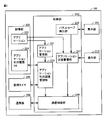
- FIG. 2 is a block diagram illustrating a specific example of a functional configuration of the mobile terminal device 100.
- the mobile terminal device 100 includes a display unit 201, an operation unit 210, a storage unit 220, a control unit 230, a monitoring timer 240, and a communication unit 250.
- the storage unit 220 includes an application 222 and an application usage history DB (Database) 224.
- the control unit 230 includes an application management unit 231, an application usage frequency management unit 233, a panel save detection unit 235, an application state management unit 237, and a communication control unit 239.
- the application management unit 231 detects an instruction for the application 222.
- the command is “start”, “operation”, “delete”, “install”, or the like of the application 222.
- the application management unit 231 determines the identification information of the application 222 (hereinafter referred to as “application identification information”) and the operation type for the application 222 (hereinafter referred to as “operation type”) according to the command. Input to the application usage frequency management unit 233.
- the application identification information includes an application ID (Identification), a name, and the like.
- the operation type is “activation”, “operation”, “deletion”, “installation” or the like of the application 222.
- the monitoring timer 240 inputs the time when the application 222 is activated to the application usage frequency management unit 233. In addition, the monitoring timer 240 inputs the time when the application 222 is installed to the application usage frequency management unit 233.
- the application usage frequency management unit 233 stores the application identification information and the operation type input by the application management unit 231 in the application usage history DB 224. In addition, the application usage frequency management unit 233 stores the activation time and installation time of the application 222 input by the monitoring timer 240 in the application usage history DB 224.
- the application usage frequency management unit 233 calculates the usage frequency of the application 222 for each type of application based on the application usage history DB 224. The calculation method of the usage frequency will be described in detail with reference to FIG.
- the application usage frequency management unit 233 calculates the usage frequency at regular intervals. For example, the certain time is set when the mobile terminal device 100 is designed. Further, the certain time may be configured to be set by the user. In one aspect, the application usage frequency management unit 233 calculates the usage frequency of the application 222 when the application 222 is activated or installed.
- the application usage frequency management unit 233 determines whether to prohibit communication of the application 222. For example, when the usage frequency of the application 222 is lower than a predetermined usage frequency, the application usage frequency management unit 233 prohibits communication performed by the application 222 (hereinafter referred to as “communication prohibited state”). The application usage frequency management unit 233 inputs the determination result to the communication control unit 239.
- the predetermined usage frequency may be set when the mobile terminal device 100 is designed.
- the predetermined usage frequency may be configured so that the user can set it.
- the display unit 201 displays an operation screen of the application 222.
- the display mode of the display unit 201 includes a display mode that does not limit the luminance and a display mode that limits the luminance (hereinafter referred to as “panel save mode”).
- panel save mode a display mode that limits the luminance
- the control unit 230 switches the display mode of the display unit 201 to the panel save mode when the operation on the mobile terminal device 100 is not accepted for a certain period of time.
- the panel save detection unit 235 detects that the display mode of the display unit 201 has been changed.
- the panel save detection unit 235 inputs the determination result to the application state management unit 237.
- the operation unit 210 receives an operation on the mobile terminal device 100.
- the operation unit 210 inputs a signal corresponding to the detected operation to the application state management unit 237.
- the operation unit 210 includes a touch panel.
- the touch panel may be any type such as a resistive film method, a surface acoustic wave method, an infrared method, an electromagnetic induction method, and a capacitance method.
- the application state management unit 237 determines whether or not the state of the application 222 has been switched.
- the state of the application 222 is a state where the application 222 is used by the user (hereinafter referred to as “foreground state”) and a state where the application 222 is not used by the user (hereinafter referred to as “background state”). )including.
- the determination result of the application state management unit 237 is input to the communication control unit 239.
- the state of the application 222 is in the foreground state when the user starts the application 222.
- the state of the application 222 becomes a foreground state when the user resumes the suspended application 222.
- the state of the application 222 is in the background state.
- the state of the application 222 becomes a background state.
- the operation screen of the application 222 is not displayed on the display unit 201, the state of the application 222 is in the background state.
- the state of the application 222 becomes a background state.
- the communication control unit 239 prohibits the application 222 from communicating with the information communication device based on the determination result of the application usage frequency management unit 233 and the determination result of the application state management unit 237. For example, when the application 222 is in a communication prohibited state and in the background state, the communication control unit 239 prohibits communication of the application 222.
- the communication control unit 239 prohibits the communication of the application 222 based on the determination result of one of the application usage frequency management unit 233 and the application state management unit 237.
- a configuration that enables communication may be used for the application 222 set by the user.
- FIG. 3 is a diagram illustrating the application usage history DB 224 stored in the storage unit 220.
- the storage unit 220 stores an application usage history DB 224.
- the application usage history DB 224 includes an application type 310, an operation type 320, and an operation date / time 330.
- the operation type 320 is “startup” or “installation” of the application 222.
- the operation date 330 is a time when the application 222 is activated or a time when the application 222 is installed.
- Application A is started at 11:00 on December 5, as indicated by line 350.
- the application A is activated on December 5th at 12:00.
- the application A is activated on December 7, 14:00.
- Application B is activated at 15:00 on December 6 as indicated by line 353.
- Application C is installed at 10:00 on December 1, as indicated by line 354. Further, the application C is activated at 12:00 on December 2, as indicated by a row 355.
- the operation date and time 330 may be any time from when the application 222 is activated until it is terminated.
- the operation date / time 330 may be a time from when the application 222 is activated until it is terminated.
- the operation date and time 330 is any time from the start of installation of the application 222 to the end.
- the operation date and time 330 may be a time from the start of installation of the application 222 to the end.
- the application usage frequency management unit 233 stores the application type 310, the operation type 320, and the operation date / time 330 in the application usage history DB 224.
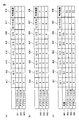
- FIG. 4 shows methods (a) to (c) as methods for calculating the usage frequency of the application 222 in a certain situation.
- the application usage frequency management unit 233 refers to the application usage history DB 224 and calculates the usage frequency of the application 222 for a certain period. For example, referring to the method (a) of FIG. 4, the application usage frequency management unit 233 determines the usage frequency 418 from the number of activations from December 1 (column 411) to December 7 (today) (column 417). Is calculated. In the method (a) of FIG. 4, the application usage frequency management unit 233 calculates the number of activations for each day, but is not limited to each day.
- the application B is started once on December 6 (column 416). For this reason, the use frequency 418 of the application B is 1.
- the communication control unit 239 prohibits the communication of the application 222 when the use frequency is lower than a predetermined frequency (hereinafter referred to as “use frequency threshold”). For example, when the usage frequency threshold is 2, communication between the applications B and C is prohibited.
- the application usage frequency management unit 233 determines the number of activations from December 1 (column 431) to December 7 (today) (column 437) and A usage frequency 418 is calculated based on the installation date and time.
- the usage frequency threshold is 5 when the usage frequency threshold is 5, communication between the applications A and B is prohibited.
- the number of uses added is set when the mobile terminal device 100 is designed. Further, the number of times of addition may be configured to be changeable by the user.
- Method (b) increases the frequency of use of applications installed in the past certain period. Thereby, since the communication of the application is permitted, the operability of the user is not impaired.
- the application usage frequency management unit 233 permits communication of the application that has been activated most recently when the usage frequency is calculated. In addition, the application usage frequency management unit 233 prohibits communication of an application that has not been activated most recently when the usage frequency is calculated.
- a coefficient is set for each day as indicated by a row 461 in the method (c) in FIG.
- the coefficient is set so as to increase as it approaches December 7 (today) (column 457).
- the coefficient for December 1 (column 451) is 0.1.
- the coefficient for December 2 (column 452) is 0.2.
- the coefficient for December 3 (column 453) is 0.3.
- the coefficient for December 4 (column 451) is 0.4.
- the coefficient for December 5 (column 455) is 0.6.
- the coefficient for December 6 (column 456) is 0.8.
- the coefficient for December 7 (column 451) is one.
- the usage frequency of the application 222 is calculated by multiplying the number of activations by a coefficient.
- the usage frequency threshold is 0.5, communication of the application C is prohibited.
- coefficient is set when the mobile terminal device 100 is designed.
- the coefficient may be configured to be changeable by the user.
- the coefficient is not limited to the above.
- FIG. 5 is a flowchart showing a part of processing executed by CPU 20 of mobile terminal device 100 in a certain aspect.
- the processing in FIG. 5 is realized by the CPU 20 executing a program. In other aspects, some or all of the processing may be performed by circuit elements or other hardware.
- step S510 the CPU 20 detects an operation on the application 222 as the application management unit 231.
- step S520 the CPU 20 registers the type, operation type, and activation time of the application 222 in the application usage history DB 224 as the application usage frequency management unit 233.
- step S530 the CPU 20 calculates the usage frequency x of the application 222 as the application usage frequency management unit 233.
- step S540 the CPU 20 determines whether the usage frequency x is equal to or higher than the usage frequency threshold C as the application usage frequency management unit 233.
- CPU 20 determines that usage frequency x is equal to or higher than usage frequency threshold C (YES in step S540)
- CPU 20 switches control to step S550. If not (NO in step S540), CPU 20 switches control to step S560.
- step S550 the CPU 20 sets the determination result R to “permitted”.
- step S560 the CPU 20 sets the determination result R to “prohibited”.
- step S570 the CPU 20 restarts the monitoring timer 240.
- step S580 the CPU 20 determines whether or not the mobile terminal device 100 is in the energy saving mode. Note that step S580 may be omitted. Step S580 may be executed at other timing, for example, before step S510.
- CPU 20 determines that the mobile terminal device is in the energy saving mode (YES in step S580)
- CPU 20 switches control to step S590. If not (NO in step S580), CPU 20 ends the process.
- step S590 the CPU 20 notifies the communication control unit 239 of the determination result R as the application usage frequency management unit 233. Thereafter, the CPU 20 ends the process.
- the mobile terminal device 100 in a certain aspect can permit communication of an application with high usage frequency and prohibit communication of an application with low usage frequency. Thereby, it becomes possible to suppress the power consumption of the portable terminal device 100 without impairing the user's convenience.
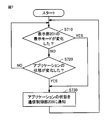
- FIG. 6 is a flowchart showing a part of processing executed by CPU 20 of portable terminal device 100 in another aspect.
- the processing in FIG. 6 differs from the flowchart in FIG. 5 in that the CPU executes step S610 and omits step S570.
- Other processing is the same. Therefore, the description of the same steps as those shown in FIG. 5 will not be repeated.
- the CPU 20 calculates the usage frequency of the application 222 at regular intervals. Specifically, in step S610, the CPU 20 determines, as the application usage frequency management unit 233, whether or not a certain time has elapsed since the monitoring timer 240 started measuring time. When CPU 20 determines that the predetermined time has elapsed (YES in step S610), CPU 20 switches control to step S530. If not (NO in step S610), CPU 20 switches control to step S610.
- the application usage frequency management unit 233 prohibits communication performed by the application 222.
- the mobile terminal device 100 can automatically switch the applicability of communication of the application at regular intervals, thereby improving the convenience for the user.
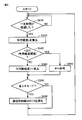
- FIG. 7 is a flowchart showing a part of processing executed by CPU 20 of portable terminal device 100 in another aspect.
- the processing in FIG. 7 is realized by the CPU 20 executing a program. In other aspects, some or all of the processing may be performed by circuit elements or other hardware.
- step S710 the CPU 20 determines whether or not the display mode of the display unit 201 has changed based on the determination result of the panel save detection unit 235.
- CPU20 switches control to step S730, when display mode changes (in step S710 YES). If not (NO in step S710), CPU 20 switches control to step S720.
- step S720 the CPU 20 determines whether or not the state of the application 222 has changed based on the determination result of the application state management unit 237.
- CPU 20 determines in step S720 that the state of application 222 has changed (YES in step S720)
- CPU 20 switches control to step S730. If not (NO in step S720), CPU 20 returns control to step S710.
- step S730 the CPU 20 notifies the communication control unit 239 of the state of the application 222 as the application state management unit 237.
- the communication control unit 239 prohibits communication performed by the application 222 based on the state of the application 222.
- the mobile terminal device 100 can prohibit communication of applications in the background state.
- the portable terminal device 100 which concerns on this Embodiment can permit communication of the application of a foreground state. For this reason, communication of applications used by the user is performed, and communication of applications not used by the user is not performed. Thereby, it becomes possible to suppress power consumption without impairing user convenience.
- 100 mobile terminal device 110 automatic transaction device, 120 network, 20 CPU, 23 antenna, 24 communication device, 25 user interface, 26 camera, 27 flash memory, 28 RAM, 29 ROM, 30 memory card drive device, 31 memory card, 32 microphone, 33 speaker, 34 audio signal processing circuit, 35 display, 36 LED, 37 data communication I / F, 38 vibrator, 39 timer, 201 display unit, 210 operation unit, 220 storage unit, 222 application, 224 application usage history DB, 230 control unit, 231 application management unit, 233 application usage frequency management unit, 235 panel save detection unit, 237 application state management unit 239 communication control unit, 240 monitor timer, 250 communication unit, 310 application type, 320 operation type, 330 operation time, 418 use frequency.
Landscapes
- Engineering & Computer Science (AREA)
- Computer Networks & Wireless Communication (AREA)
- Signal Processing (AREA)
- Human Computer Interaction (AREA)
- Telephone Function (AREA)
Priority Applications (2)
| Application Number | Priority Date | Filing Date | Title |
|---|---|---|---|
| US14/649,602 US20150327179A1 (en) | 2013-02-26 | 2014-02-17 | Portable terminal device |
| CN201480009897.2A CN105009555A (zh) | 2013-02-26 | 2014-02-17 | 便携终端装置 |
Applications Claiming Priority (2)
| Application Number | Priority Date | Filing Date | Title |
|---|---|---|---|
| JP2013035810A JP6016670B2 (ja) | 2013-02-26 | 2013-02-26 | 携帯端末装置 |
| JP2013-035810 | 2013-02-26 |
Publications (1)
| Publication Number | Publication Date |
|---|---|
| WO2014132824A1 true WO2014132824A1 (ja) | 2014-09-04 |
Family
ID=51428096
Family Applications (1)
| Application Number | Title | Priority Date | Filing Date |
|---|---|---|---|
| PCT/JP2014/053605 Ceased WO2014132824A1 (ja) | 2013-02-26 | 2014-02-17 | 携帯端末装置 |
Country Status (4)
| Country | Link |
|---|---|
| US (1) | US20150327179A1 (enExample) |
| JP (1) | JP6016670B2 (enExample) |
| CN (1) | CN105009555A (enExample) |
| WO (1) | WO2014132824A1 (enExample) |
Cited By (2)
| Publication number | Priority date | Publication date | Assignee | Title |
|---|---|---|---|---|
| CN106155599A (zh) * | 2015-01-29 | 2016-11-23 | 富士施乐株式会社 | 设备管理系统、中继装置和中继方法 |
| EP3101958A1 (en) * | 2015-06-05 | 2016-12-07 | Lg Electronics Inc. | Mobile terminal and method for controlling the same |
Families Citing this family (4)
| Publication number | Priority date | Publication date | Assignee | Title |
|---|---|---|---|---|
| JP2578922B2 (ja) | 1988-07-04 | 1997-02-05 | 日本電信電話株式会社 | 暗号化による通信端末機器の機器認識番号確認方法 |
| CN105306743A (zh) * | 2015-09-30 | 2016-02-03 | 小米科技有限责任公司 | 屏幕控制方法及装置 |
| JP6029781B1 (ja) | 2016-02-04 | 2016-11-24 | 京セラ株式会社 | 通信装置、dns処理方法、およびプログラム |
| JP6532851B2 (ja) * | 2016-10-18 | 2019-06-19 | 京セラ株式会社 | 通信装置、dns処理方法、およびプログラム |
Citations (3)
| Publication number | Priority date | Publication date | Assignee | Title |
|---|---|---|---|---|
| JP2000148454A (ja) * | 1998-11-10 | 2000-05-30 | Ricoh Co Ltd | 通信端末装置およびセンター装置 |
| JP2011238124A (ja) * | 2010-05-12 | 2011-11-24 | Fujitsu Toshiba Mobile Communications Ltd | 携帯型電子機器 |
| JP2014036410A (ja) * | 2012-08-10 | 2014-02-24 | Kyocera Corp | 携帯端末装置、プログラムおよび携帯端末装置の制御方法 |
Family Cites Families (9)
| Publication number | Priority date | Publication date | Assignee | Title |
|---|---|---|---|---|
| US9274807B2 (en) * | 2006-04-20 | 2016-03-01 | Qualcomm Incorporated | Selective hibernation of activities in an electronic device |
| US7900243B2 (en) * | 2006-10-19 | 2011-03-01 | Oracle America, Inc. | Method and system for managing execution of an application module |
| US8510743B2 (en) * | 2007-10-31 | 2013-08-13 | Google Inc. | Terminating computer applications |
| US20100277326A1 (en) * | 2009-05-01 | 2010-11-04 | BoxTone, Inc. | Method and system for monitoring portable communication devices |
| US8244311B2 (en) * | 2009-12-29 | 2012-08-14 | International Business Machines Corporation | Time-related power systems |
| CN101873385A (zh) * | 2010-06-04 | 2010-10-27 | 北京播思软件技术有限公司 | 一种实现快速进入手持终端省电模式的装置及方法 |
| CN102521041B (zh) * | 2011-12-14 | 2014-10-08 | 华为终端有限公司 | 一种处理应用程序的方法及无线手持设备 |
| JP5942416B2 (ja) * | 2011-12-21 | 2016-06-29 | 富士通株式会社 | 情報処理装置の制御プログラム、制御方法及び情報処理装置 |
| CN102811289B (zh) * | 2012-08-15 | 2014-12-10 | 东莞宇龙通信科技有限公司 | 终端和终端的电源管理方法 |
-
2013
- 2013-02-26 JP JP2013035810A patent/JP6016670B2/ja not_active Expired - Fee Related
-
2014
- 2014-02-17 CN CN201480009897.2A patent/CN105009555A/zh active Pending
- 2014-02-17 US US14/649,602 patent/US20150327179A1/en not_active Abandoned
- 2014-02-17 WO PCT/JP2014/053605 patent/WO2014132824A1/ja not_active Ceased
Patent Citations (3)
| Publication number | Priority date | Publication date | Assignee | Title |
|---|---|---|---|---|
| JP2000148454A (ja) * | 1998-11-10 | 2000-05-30 | Ricoh Co Ltd | 通信端末装置およびセンター装置 |
| JP2011238124A (ja) * | 2010-05-12 | 2011-11-24 | Fujitsu Toshiba Mobile Communications Ltd | 携帯型電子機器 |
| JP2014036410A (ja) * | 2012-08-10 | 2014-02-24 | Kyocera Corp | 携帯端末装置、プログラムおよび携帯端末装置の制御方法 |
Cited By (2)
| Publication number | Priority date | Publication date | Assignee | Title |
|---|---|---|---|---|
| CN106155599A (zh) * | 2015-01-29 | 2016-11-23 | 富士施乐株式会社 | 设备管理系统、中继装置和中继方法 |
| EP3101958A1 (en) * | 2015-06-05 | 2016-12-07 | Lg Electronics Inc. | Mobile terminal and method for controlling the same |
Also Published As
| Publication number | Publication date |
|---|---|
| CN105009555A (zh) | 2015-10-28 |
| JP2014165725A (ja) | 2014-09-08 |
| US20150327179A1 (en) | 2015-11-12 |
| JP6016670B2 (ja) | 2016-10-26 |
Similar Documents
| Publication | Publication Date | Title |
|---|---|---|
| US10732696B2 (en) | Method and apparatus for wake-up control of intelligent terminal | |
| EP3113549B1 (en) | Method and device for waking up mcu chip | |
| JP6016670B2 (ja) | 携帯端末装置 | |
| US10088889B2 (en) | Method and device for waking up a controller | |
| CN110930964B (zh) | 一种显示屏亮度调节方法、装置、存储介质及终端 | |
| CN103702028A (zh) | 一种控制拍摄的方法、装置及终端设备 | |
| CN106940997B (zh) | 一种向语音识别系统发送语音信号的方法和装置 | |
| WO2022042485A1 (zh) | 近场通信模块的控制方法、装置及电子设备 | |
| KR20150121887A (ko) | 이동단말기 제어방법 | |
| CN110543333B (zh) | 针对处理器的休眠处理方法、装置、移动终端和存储介质 | |
| CN112198954A (zh) | 帧率设置方法、装置、存储介质及移动终端 | |
| CN110505335B (zh) | 发声控制方法、装置、电子装置及计算机可读介质 | |
| CN111026456A (zh) | 应用管理方法、装置、存储介质及电子设备 | |
| CN110312995A (zh) | 应用程序加速启动方法、装置及终端 | |
| CN117112045A (zh) | 一种应用程序启动方法、装置、电子设备和存储介质 | |
| WO2010092994A1 (ja) | 情報処理装置 | |
| US11736608B2 (en) | Call control method and apparatus, and storage medium and terminal device | |
| JP5947170B2 (ja) | 表示装置ならびに視線入力制御プログラムおよび方法 | |
| CN111263008A (zh) | 一种来电提醒方法、装置、存储介质及移动终端 | |
| CN106033358B (zh) | 一种应用程序的批量安装方法和装置 | |
| CN113079249B (zh) | 提示方法、装置、存储介质及移动终端 | |
| JP6445718B2 (ja) | プロセス管理方法、装置、およびデバイス | |
| CN111897472A (zh) | 按键分时管理方法、系统、存储介质及移动终端 | |
| CN111600986A (zh) | 屏幕使用时间检测方法、系统、存储介质及移动终端 | |
| CN112261536A (zh) | 耳机控制方法、装置、终端设备及存储介质 |
Legal Events
| Date | Code | Title | Description |
|---|---|---|---|
| 121 | Ep: the epo has been informed by wipo that ep was designated in this application |
Ref document number: 14756992 Country of ref document: EP Kind code of ref document: A1 |
|
| WWE | Wipo information: entry into national phase |
Ref document number: 14649602 Country of ref document: US |
|
| NENP | Non-entry into the national phase |
Ref country code: DE |
|
| 122 | Ep: pct application non-entry in european phase |
Ref document number: 14756992 Country of ref document: EP Kind code of ref document: A1 |