WO2014132400A1 - Robot system - Google Patents
Robot system Download PDFInfo
- Publication number
- WO2014132400A1 WO2014132400A1 PCT/JP2013/055466 JP2013055466W WO2014132400A1 WO 2014132400 A1 WO2014132400 A1 WO 2014132400A1 JP 2013055466 W JP2013055466 W JP 2013055466W WO 2014132400 A1 WO2014132400 A1 WO 2014132400A1
- Authority
- WO
- WIPO (PCT)
- Prior art keywords
- robot
- annular member
- jig
- hole
- robot system
- Prior art date
Links
Images


Classifications
-
- B—PERFORMING OPERATIONS; TRANSPORTING
- B25—HAND TOOLS; PORTABLE POWER-DRIVEN TOOLS; MANIPULATORS
- B25J—MANIPULATORS; CHAMBERS PROVIDED WITH MANIPULATION DEVICES
- B25J9/00—Programme-controlled manipulators
- B25J9/16—Programme controls
- B25J9/1679—Programme controls characterised by the tasks executed
- B25J9/1687—Assembly, peg and hole, palletising, straight line, weaving pattern movement
-
- B—PERFORMING OPERATIONS; TRANSPORTING
- B23—MACHINE TOOLS; METAL-WORKING NOT OTHERWISE PROVIDED FOR
- B23P—METAL-WORKING NOT OTHERWISE PROVIDED FOR; COMBINED OPERATIONS; UNIVERSAL MACHINE TOOLS
- B23P19/00—Machines for simply fitting together or separating metal parts or objects, or metal and non-metal parts, whether or not involving some deformation; Tools or devices therefor so far as not provided for in other classes
- B23P19/001—Article feeders for assembling machines
Definitions
- the disclosed embodiment relates to a robot system.
- Such robot systems include, for example, an assembly system that assembles a mechanical product such as a motor using a robot while supplying parts by a transfer device or the like.
- annular member such as an O-ring is often used as a part. Since such an annular member is made of a soft material and is often amorphous, a dedicated device has been used for its conveyance (see, for example, Patent Document 1).
- the “belt transport device” disclosed in Patent Document 1 has a base that is pivotably attached to a frame, suspends an annular member from an arm around which the belt is suspended, and feeds out the belt and the belt.
- the annular member is conveyed by switching the direction.
- the belt conveying device since the above-described belt conveying device requires a mechanism such as an arm or a belt, the installation space and cost are easily increased and inefficient. Also, for example, it is not suitable for transporting small annular members such as packing, which are generally smaller than O-rings.
- the small annular member may be made of a soft material, so that it is difficult for the robot to hold it and it is difficult to attach it.
- One aspect of the embodiment has been made in view of the above, and an object thereof is to provide a robot system capable of efficiently and reliably carrying and attaching a small annular member.
- the robot system includes a robot and an instruction unit.
- the robot includes a robot hand including a mechanism for gripping an object to be gripped.
- the instructing unit holds the annular member by inserting the jig formed in a substantially rod shape as the object to be grasped into the hole of the annular member, and instructs the robot to carry the jig together. .
- the small annular member can be transported and attached efficiently and reliably.
- FIG. 1A is a schematic plan view showing the configuration of the robot system according to the first embodiment.
- FIG. 1B is a schematic perspective view of a workpiece and an annular member.
- 1C is a schematic cross-sectional view taken along line A-A ′ shown in FIG. 1B.
- FIG. 2 is a block diagram of the robot system according to the first embodiment.
- FIG. 3A is a schematic front view showing the configuration of the robot.
- FIG. 3B is a schematic plan view showing the configuration of the robot.
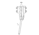
- FIG. 4 is a schematic perspective view showing the configuration of the hand.
- FIG. 5A is a schematic diagram (part 1) for describing a series of operations from conveyance to attachment of an annular member.
- FIG. 5A is a schematic diagram (part 1) for describing a series of operations from conveyance to attachment of an annular member.
- FIG. 5B is a schematic diagram (part 2) for explaining a series of operations from conveyance to attachment of the annular member.
- FIG. 5C is a schematic diagram (No. 3) for explaining a series of operations from conveyance to attachment of the annular member.
- FIG. 5D is a schematic diagram (part 4) for describing a series of operations from conveyance to attachment of the annular member.
- FIG. 5E is a schematic diagram (No. 5) for describing a series of operations from conveyance to attachment of the annular member.
- FIG. 5F is a schematic diagram (No. 6) for describing a series of operations from conveyance to attachment of the annular member.
- FIG. 5G is a schematic diagram (No. 7) for describing a series of operations from conveyance to attachment of the annular member.
- FIG. 5H is a schematic diagram (No. 8) for describing a series of operations from conveyance to attachment of the annular member.
- FIG. 6A is a schematic diagram (part 1) for explaining a series of operations according to the second embodiment.
- FIG. 6B is a schematic diagram (part 2) for describing a series of operations according to the second embodiment.
- FIG. 6C is a schematic diagram (part 3) for describing a series of operations according to the second embodiment.
- FIG. 6D is a schematic diagram (part 4) for describing a series of operations according to the second embodiment.
- FIG. 6E is a schematic diagram (part 5) for describing a series of operations according to the second embodiment.
- FIG. 1A is a schematic plan view showing the configuration of the robot system 1 according to the first embodiment.
- FIG. 1A shows a three-dimensional orthogonal coordinate system including the Z axis with the vertical direction as the positive direction for easy understanding. Such an orthogonal coordinate system may be shown in other drawings used in the following description. In the present embodiment, it is assumed that the positive direction of the X axis points to the front of the robot 10.
- a component composed of a plurality of components only a part of the plurality of components may be provided with a reference numeral, and the provision of a reference numeral may be omitted for the others. In such a case, it is assumed that a part with the reference numeral and the other have the same configuration.
- the robot system 1 includes a cell 2 that forms a rectangular parallelepiped work space.
- the robot system 1 includes a robot 10, a work table 20, a supply table 30, and a camera 40 inside the cell 2.
- the robot system 1 includes a control device 50 outside the cell 2.
- the control device 50 is connected to various devices in the cell 2 such as the robot 10 and the camera 40 so that information can be transmitted.
- control device 50 is a controller that controls the operation of various connected devices, and includes various control devices, arithmetic processing devices, storage devices, and the like. Details of the control device 50 will be described later with reference to FIG.
- control device 50 of one housing is shown, but the present invention is not limited to this.
- the control device 50 is composed of a plurality of housings associated with various devices to be controlled. Also good. Further, it may be disposed inside the cell 2.
- the robot 10 is a dual-arm manipulator that operates in response to an operation instruction from the control device 50, and describes a robot hand (hereinafter, “hand”) to be described later for each arm (hereinafter, referred to as “arm”). ). Details of the configuration of the robot 10 will be described later with reference to FIGS. 3A to 4.
- the work table 20 is a place where the robot 10 performs a series of work from conveyance to attachment of the annular member P. As shown in FIG. 1A, the work table 20 includes a mounting table 21.
- the mounting base 21 is a place where the robot 10 attaches the annular member P to the workpiece W.
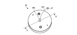
- FIG. 1B is a schematic perspective view of the workpiece W and the annular member P.
- 1C is a schematic cross-sectional view taken along line A-A ′ shown in FIG. 1B.
- the workpiece W in the present embodiment is a member formed in a low-profile, substantially columnar shape used as a motor bracket or the like.
- the workpiece W has a flange portion (described later in FIG. 5E and the like), and a hole portion Wh that is a through-hole penetrating from the upper surface side to the lower surface side is formed in a shape that can be fitted to the annular member P.
- the robot system 1 is attached by fitting the annular member P into the hole Wh (see the arrow 101 in FIG. 1B and FIG. 1C).
- the annular member P shall be formed from soft materials, such as rubber
- the supply stand 30 is a place where, for example, the annular member P supplied from the outside is stocked together with the attachment stand 21.
- the supply base 30 includes a parts feeder (described later in FIG. 5C and the like), and the annular member P is held by the parts feeder for each type of difference such as the size and shape of the inner diameter.
- the annular members P1 and P2 shown in FIG. 1A represent differences in the type of the annular member P.
- the above-described mounting base 21 is provided with jigs J corresponding to the difference in the type of the annular member P.
- the jigs J1 and J2 shown in FIG. 1A represent differences in the type of the jig J.
- the annular member P is transported and attached while the annular member P is held using the jig J applied to the robot 10. Details of this point will be described later with reference to FIGS. 5A to 5H.
- the camera 40 is an image pickup device having a predetermined image pickup area, and picks up an image of the workpiece W placed on the mounting base 21. Although it is difficult to understand in FIG. 1A, the camera 40 is suspended above the mounting base 21 from the ceiling portion of the cell 2 in this embodiment. Here, the camera 40 may be provided in the vicinity of the hand 14 (described later in FIG. 2) of the robot 10.
- the work information related to the work W is acquired based on the imaging data of the camera 40.
- the present invention is not limited to the imaging device, and a detection device such as an optical sensor may be used.
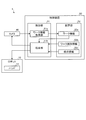
- FIG. 2 is a block diagram of the robot system 1 according to the first embodiment.
- FIG. 2 only the components necessary for the description of the robot system 1 are shown, and descriptions of general components are omitted.
- control device 50 In the description using FIG. 2, the internal configuration of the control device 50 will be mainly described, and the description of various devices already shown in FIG. 1A may be simplified.
- the control device 50 includes a control unit 51 and a storage unit 52.
- the control unit 51 further includes a work information acquisition unit 51a and an instruction unit 51b.
- the storage unit 52 is a storage device such as a hard disk drive or a nonvolatile memory, and stores work information 52a, work identification information 52b, and teaching information 52c.
- control device 50 not all of the components of the control device 50 shown in FIG. 2 need be arranged in the control device 50 alone.
- any or all of the work information 52a, work identification information 52b, and teaching information 52c stored in the storage unit 52 may be stored in an internal memory of the robot 10.
- the control unit 51 performs overall control of the control device 50.
- the workpiece information acquisition unit 51a receives imaging data of the workpiece W from the camera 40 and stores it as workpiece information 52a.
- the instruction unit 51b matches the workpiece information 52a and the workpiece identification information 52b to identify the type of the workpiece W.
- the workpiece identification information 52b is information for identifying the type of the workpiece W such as the shape and size of the workpiece W and the position and size of the hole Wh.
- Such work identification information 52b is registered in the storage unit 52 in advance.
- the teaching information 52c is information including a “job” which is a specific program for actually operating the robot 10 according to a specific workpiece W, and is input via an input device (not shown) (for example, a programming pendant). Registered in advance.
- the “job” includes a mode of attachment operation applied to the workpiece W (specifically, information such as which annular member P is used for which workpiece W and which jig J is used for the annular member P) ) Is included.
- the instruction unit 51b generates an operation signal for operating the robot 10 based on the “job”.
- the operation signal is generated as a pulse signal for the servo motor mounted on each joint portion of the robot 10, for example.
- the instruction unit 51b causes the camera 40 to appropriately capture new imaging data at a predetermined timing in a series of operations performed by the robot 10.
- the robot 10 includes a hand 14. As described above, since the robot 10 is a double-arm robot, the hand 14 is a generic term for a pair of left and right hands.
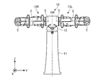
- FIG. 3A is a schematic front view illustrating the configuration of the robot 10
- FIG. 3B is a schematic plan view illustrating the configuration of the robot 10.
- the robot 10 is a double-armed multi-axis robot. Specifically, the robot 10 includes a base part 11, a body part 12, a left arm part 13L, and a right arm part 13R.
- the base portion 11 is fixed to the floor surface or the like inside the cell 2 (see FIG. 1A), and supports the trunk portion 12 at the tip so that it can turn around the axis SW (around the axis SW in FIG. 3A). (See the double arrow).
- the trunk portion 12 is supported at the base end portion by the base portion 11, and supports the base end portion of the right arm portion 13R at the right shoulder so that the base end portion can be rotated around the axis S.
- the base end portion of the left arm portion 13L is supported at the left shoulder so as to be rotatable around the axis S (see both double arrows around the axis S in the figure).
- Each of the left arm portion 13L and the right arm portion 13R includes a plurality of links and joint portions, and can rotate around the axes S, E, and T at each joint portion from the base end portion to the distal end portion. (See double arrows around the axes S, E and T in the figure).
- the left arm portion 13L and the right arm portion 13R can rotate about the axis L, the axis U, the axis R, and the axis B, respectively (the axis L, the axis U, (See double arrows around axis R and axis B). That is, the robot 10 has 7 axes per arm part.
- the robot 10 performs various multi-axis operations combining the two 7-axis arms and the turning around the axis SW based on the operation instruction from the control device 50.
- the right hand 14R is attached to the terminal movable part around the axis T of the right arm part 13R
- the left hand 14L is attached to the terminal movable part around the axis T of the left arm part 13L.
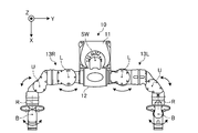
- FIG. 4 is a schematic perspective view showing the configuration of the hand 14.
- the right hand 14R will be described as an example of the hand 14, but the left hand 14L may be used.
- the right hand 14R is attached to the terminal movable portion of the right arm portion 13R.
- the right hand 14R has a pair of gripping claws 14Ra, and grips the gripping object by closing the gripping claws 14Ra in the direction of the arrow 401 in the drawing and sandwiching the gripping target object.
- the gripping object of the right hand 14R is a jig J.
- a series of operations from the conveyance to the attachment of the annular member P including the configuration of the jig J will be described with reference to FIGS. 5A to 5H.
- FIGS. 5A to 5H are schematic views (No. 1) to (No. 8) for explaining a series of operations from the conveyance to the attachment of the annular member P.
- FIG. A series of operations performed by the robot 10 described below with reference to FIGS. 5A to 5H are performed based on an instruction from the instruction unit 51b as described above.
- the jig J has a shape formed in a substantially rod shape.
- the jig J includes a main body portion Ja and a handle portion Jb.
- the main body portion Ja is a portion that is inserted into the hole of the annular member P, and the outer diameter thereof is formed to be substantially the same as the inner diameter (that is, the diameter of the hole) of the annular member P.
- the grip portion Jb is a portion that is gripped by the right hand 14R, and the shape thereof is formed to be constant even if the inner diameter of the annular member P is different.
- the jig J has a mass to which a larger gravitational force than a frictional force generated between the jig J and the annular member P when inserted into the hole of the annular member P is applied.
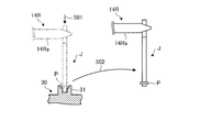
- the instruction unit 51b instructs the robot 10 to grip the jig J using the gripping claws 14Ra of the right hand 14R when transporting the annular member P.
- the instruction unit 51 b drives the right arm unit 13 ⁇ / b> R while holding the jig J, and holds the annular member held by the parts feeder 31 included in the supply base 30.
- the robot 10 is instructed to insert the jig J into the hole P (see arrow 501 in the figure).
- the annular member P is locked to the jig J by the frictional force generated between the annular member P and the inserted jig J. Then, the instruction unit 51b operates the robot to move the annular member P locked to the jig J to the mounting base 21 by driving the right arm portion 13R while holding the jig J. 10 (see arrow 502 in the figure).
- the instruction unit 51b instructs the robot 10 to insert the jig J into the hole Wh of the workpiece W placed on the mounting base 21 (see the arrow 503 in the figure). ).
- the hole Wh of the workpiece W has a concentric shape in plan view with the flange Wf, and the first inner diameter d1 and the second inner diameter d2 are Have.
- the first inner diameter d1 is substantially the same as the outer diameter of the annular member P.
- the second inner diameter d2 is larger than the outer diameter Jd of the jig J and smaller than the first inner diameter d1. Therefore, it can be said that the hole Wh has a shape that allows only the jig J to pass therethrough and holds the annular member P inside.
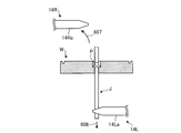
- the mounting table 21 and the work table 20 are provided with a hole 21a and a hole 20a in association with the position of the hole Wh of the workpiece W, respectively. Therefore, the upper surface of the workpiece W is penetrated from the lower surface of the work table 20 through the holes Wh, 21a and 20a.
- the inner diameters of the hole portion 21a and the hole portion 20a are at least equal to or greater than the above-described second inner diameter d2.
- a jig receiving portion 22 having a space communicating with the hole portion 20a is provided on the lower surface of the work table 20.
- the jig receiving portion 22 is provided with an opening into which at least one set of gripping claws 14Ra can be inserted.
- the instruction unit 51b performs an operation on the robot 10 to open the gripping claw 14Ra and release the gripped jig J from the state where the jig J is inserted into the hole Wh of the workpiece W. (See arrow 504 in the figure). Then, the jig J released from the robot 10 falls into the hole Wh (see arrow 505 in the figure).
- the jig J moves through the holes Wh, 21a, and 20a while leaving the annular member P to the flange portion Wf by a gravitational action larger than the frictional force with the annular member P. It falls to the receiving part 22. Thereby, the annular member P is attached to the hole Wh of the workpiece W.
- the jig J that has dropped onto the jig receiving unit 22 is collected when the instruction unit 51b instructs the robot 10 to perform a collecting operation, and is used for the next conveyance and attachment of the annular member P.
- the collecting operation is an operation of inserting and holding the gripping claws 14Ra from the opening of the jig receiving portion 22 and transporting the gripping claws 14Ra to the mounting base 21.
- the annular member P is held and transported by the robot 10 using the jig J corresponding to the type of the annular member P. There is no need for special equipment for transport. Therefore, an efficient system with reduced installation space and cost can be configured.
- the annular member P is moved to the workpiece W by using the gravity action generated by inserting and dropping the jig J that holds the annular member P into the hole Wh of the workpiece W. We decided to attach to. Therefore, even the small annular member P can be efficiently and reliably attached to the workpiece W without causing the robot 10 to perform complicated operations.
- the robot system includes a robot and an instruction unit.
- the robot includes a robot hand including a mechanism for gripping an object to be gripped.
- the instruction unit holds the annular member while holding the jig formed in a substantially rod shape as the object to be grasped, and instructs the robot to perform an operation of transporting the jig together with the jig. .
- the small annular member can be transported and attached efficiently and reliably.
- (Second Embodiment) 6A to 6E are schematic views (No. 1) to (No. 5) for explaining a series of operations according to the second embodiment.
- the robot system 1 ′ according to the second embodiment (not shown, but hereinafter, given the sign “1 ′” for convenience) is mainly the same as the robot system 1 according to the first embodiment described above. Different parts will be described, and descriptions of common components may be simplified or omitted.
- the robot 10 includes a right hand 14 ⁇ / b> R and a left hand 14 ⁇ / b> L.
- the left hand 14L has the same configuration as the right hand 14R shown in FIG.
- the gripping claws of the left hand 14L are denoted by “14La” for convenience.
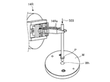
- FIGS. 6A and 6B the parts feeder 31 'of the supply base 30 is different from the first embodiment.
- 6A is a schematic diagram in a side view
- FIG. 6B is a schematic diagram in a plan view.
- the parts feeder 31 ′ is formed, for example, in a substantially U shape in plan view so as to have an opening 31 ′ a partially opened, and the annular member P It has a structure to hold.
- the lower part of the parts feeder 31 ' is opened to such an extent that a pair of gripping claws 14La of the left hand 14L can be inserted.
- the instruction unit 51b holds the jig J with the right hand 14R and the annular member P held by the parts feeder 31 ′.
- the robot 10 is instructed to insert the jig J into the hole (see arrow 601 in the figure).
- the instruction unit 51b instructs the robot 10 to grip the tip of the inserted jig J using the gripping claws 14La of the left hand 14L (see arrow 602 in the figure).
- the instruction unit 51b pulls the annular member P together with the jig J from the opening 31'a while holding the jig J with both the right hand 14R and the left hand 14L, and the right arm unit 13R and the left arm unit 13L is driven to instruct the robot 10 to carry the annular member P to the mounting base 21 (see arrow 603 in the figure).
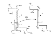
- the instruction unit 51b uses the right hand 14R after positioning the tip of the jig J to the upper part of the hole Wh of the work W and releasing the jig J by the left hand 14L.
- the robot 10 is instructed to insert the jig J into the hole Wh (see arrows 604 and 605 in the figure).
- the instruction unit 51b instructs the robot 10 to move the left hand 14L, which has been released from the jig J, to the lower surface side of the workpiece W (see an arrow 606 in the drawing).
- the mounting table 21 and the work table 20 are not shown for convenience of explanation.
- the instruction unit 51b grips the tip of the jig J inserted through the hole Wh using the left hand 14L and holds the jig J by the right hand 14R.
- the robot 10 is instructed to unravel (see arrow 607 in the figure).
- the instruction unit 51b instructs the robot 10 to drive the left arm unit 13L and pull out the jig J from the lower surface side of the workpiece W using the left hand 14L (see arrow 608 in the figure). ). Thereby, after the jig J is pulled out, the annular member P is attached to the hole Wh of the workpiece W.
- the annular member P is held and transported between the right hand 14R and the left hand 14L. Therefore, for example, even when there is a possibility that the annular member P is loosely fitted to the jig J due to variations in the annular member P, the annular member P can be reliably conveyed.
- the jig J is pulled out from the lower surface side of the workpiece W using the left hand 14 ⁇ / b> L, so that the annular member P can be reliably attached to the workpiece W.
- the exclusive apparatus for conveying the annular member P etc. are not required similarly to 1st Embodiment, the efficient system which suppressed installation space and cost can be comprised.
- the annular member has been described as being made of a soft material such as rubber. However, each of the embodiments described above is also applicable when the annular member is made of a hard member such as metal. May apply.
- the dual-arm robot is exemplified, but the present invention is not limited to this.
- a multi-arm robot having three or more arms may be used.
- Two single-arm robots having one arm may be provided.
- a multi-axis robot having seven axes per arm is illustrated, but the number of axes is not limited.
Abstract
In order to solve the problem of efficiently and reliably conveying small annular members and attaching same, this robot system (1) comprises a robot (10) and an instruction unit (51b). The robot (10) comprises a robot hand (hand) (14) that includes a mechanism that grasps objects to be grasped. The instruction unit (51b) instructs the robot (10) to perform an operation whereby an annular member (P) is held, by grasping a jig (J) formed in a substantially rod shape, using said jig as the object to be grasped, inserting same into a hole in the annular member (P), and conveying each jig (J).
Description
開示の実施形態は、ロボットシステムに関する。
The disclosed embodiment relates to a robot system.
従来、製品の生産ラインなどにおいて人によってなされていた所定の作業をロボットに行わせることで、生産ラインの効率化を図るロボットシステムが種々提案されている。
Various types of robot systems have been proposed for improving the efficiency of a production line by causing a robot to perform a predetermined operation that has been conventionally performed by a person in a product production line.
かかるロボットシステムには、たとえば、搬送装置などによって部品の供給を行いつつ、ロボットを用いてモータのような機械製品を組み立てる組立システムがある。
Such robot systems include, for example, an assembly system that assembles a mechanical product such as a motor using a robot while supplying parts by a transfer device or the like.
ところで、このような機械製品を組み立てる組立システムの場合、部品として、Oリングのような環状部材が用いられることも多い。かかる環状部材は、軟性素材からなり、無定形である場合も多いため、その搬送には専用装置が用いられてきた(たとえば、特許文献1参照)。
Incidentally, in the case of an assembly system for assembling such a machine product, an annular member such as an O-ring is often used as a part. Since such an annular member is made of a soft material and is often amorphous, a dedicated device has been used for its conveyance (see, for example, Patent Document 1).
なお、特許文献1に開示の「ベルト搬送装置」は、フレームに対して基部を旋回可能に取り付けられ、ベルトが架け渡されたアームへ環状部材を吊り下げて、アームの差し出し方向およびベルトの送り出し方向を切り替えることで環状部材を搬送するものである。
In addition, the “belt transport device” disclosed in Patent Document 1 has a base that is pivotably attached to a frame, suspends an annular member from an arm around which the belt is suspended, and feeds out the belt and the belt. The annular member is conveyed by switching the direction.
しかしながら、上述した従来技術には、小型の環状部材の搬送および取り付けを効率的かつ確実に行う点で更なる改善の余地がある。
However, the above-described prior art has room for further improvement in terms of efficiently and reliably transporting and mounting small annular members.
たとえば、上述のベルト搬送装置はアームやベルトといった機構を要するため、設置スペースやコストがかさみやすく、非効率的であった。また、たとえば、一般にOリングなどよりも小さい、パッキンのような小型の環状部材の搬送には適していなかった。
For example, since the above-described belt conveying device requires a mechanism such as an arm or a belt, the installation space and cost are easily increased and inefficient. Also, for example, it is not suitable for transporting small annular members such as packing, which are generally smaller than O-rings.
また、小型の環状部材は、軟性素材からなることもあって、ロボットに把持させにくく、その取り付けも行いにくかった。
Also, the small annular member may be made of a soft material, so that it is difficult for the robot to hold it and it is difficult to attach it.
実施形態の一態様は、上記に鑑みてなされたものであって、小型の環状部材の搬送および取り付けを効率的かつ確実に行うことができるロボットシステムを提供することを目的とする。
One aspect of the embodiment has been made in view of the above, and an object thereof is to provide a robot system capable of efficiently and reliably carrying and attaching a small annular member.
実施形態の一態様に係るロボットシステムは、ロボットと、指示部とを備える。前記ロボットは、把持対象物を把持する機構を含むロボットハンドを具備する。前記指示部は、略棒状に形成されたジグを前記把持対象物として把持しながら環状部材の孔に差し込むことで該環状部材を保持し、前記ジグごと搬送する動作を前記ロボットに対して指示する。
The robot system according to an aspect of the embodiment includes a robot and an instruction unit. The robot includes a robot hand including a mechanism for gripping an object to be gripped. The instructing unit holds the annular member by inserting the jig formed in a substantially rod shape as the object to be grasped into the hole of the annular member, and instructs the robot to carry the jig together. .
実施形態の一態様によれば、小型の環状部材の搬送および取り付けを効率的かつ確実に行うことができる。
According to one aspect of the embodiment, the small annular member can be transported and attached efficiently and reliably.
以下、添付図面を参照して、本願の開示するロボットシステムの実施形態を詳細に説明する。なお、以下に示す実施形態によりこの発明が限定されるものではない。
Hereinafter, embodiments of a robot system disclosed in the present application will be described in detail with reference to the accompanying drawings. In addition, this invention is not limited by embodiment shown below.
また、以下では、説明の便宜上、被加工品(ワーク)へ環状部材を取り付ける工程に特化したロボットシステムを例に挙げて説明を行うが、一製品が完成に至るまでの部分的な工程の一例とみなしてよい。
In the following, for convenience of explanation, a robot system specialized in the process of attaching an annular member to a workpiece (workpiece) will be described as an example, but a partial process until one product is completed will be described. It may be considered as an example.
(第1の実施形態)
図1Aは、第1の実施形態に係るロボットシステム1の構成を示す平面模式図である。なお、図1Aには、説明を分かりやすくするために、鉛直上向きを正方向とするZ軸を含む3次元の直交座標系を図示している。かかる直交座標系は、以下の説明で用いる他の図面においても示す場合がある。なお、本実施形態では、X軸の正方向がロボット10の前方を指すものとする。 (First embodiment)
FIG. 1A is a schematic plan view showing the configuration of therobot system 1 according to the first embodiment. Note that FIG. 1A shows a three-dimensional orthogonal coordinate system including the Z axis with the vertical direction as the positive direction for easy understanding. Such an orthogonal coordinate system may be shown in other drawings used in the following description. In the present embodiment, it is assumed that the positive direction of the X axis points to the front of the robot 10.
図1Aは、第1の実施形態に係るロボットシステム1の構成を示す平面模式図である。なお、図1Aには、説明を分かりやすくするために、鉛直上向きを正方向とするZ軸を含む3次元の直交座標系を図示している。かかる直交座標系は、以下の説明で用いる他の図面においても示す場合がある。なお、本実施形態では、X軸の正方向がロボット10の前方を指すものとする。 (First embodiment)
FIG. 1A is a schematic plan view showing the configuration of the
また、以下では、複数個で構成される構成要素については、複数個のうちの一部にのみ符号を付し、その他については符号の付与を省略する場合がある。かかる場合、符号を付した一部とその他とは同様の構成であるものとする。
Also, in the following, for a component composed of a plurality of components, only a part of the plurality of components may be provided with a reference numeral, and the provision of a reference numeral may be omitted for the others. In such a case, it is assumed that a part with the reference numeral and the other have the same configuration.
図1Aに示すように、ロボットシステム1は、直方体状の作業スペースを形成するセル2を備える。また、ロボットシステム1は、かかるセル2の内部に、ロボット10と、作業台20と、供給台30と、カメラ40とを備える。
As shown in FIG. 1A, the robot system 1 includes a cell 2 that forms a rectangular parallelepiped work space. The robot system 1 includes a robot 10, a work table 20, a supply table 30, and a camera 40 inside the cell 2.
また、ロボットシステム1は、セル2の外部に制御装置50を備える。制御装置50は、ロボット10やカメラ40といったセル2内部の各種装置と情報伝達可能に接続される。
In addition, the robot system 1 includes a control device 50 outside the cell 2. The control device 50 is connected to various devices in the cell 2 such as the robot 10 and the camera 40 so that information can be transmitted.
ここで、制御装置50は、接続された各種装置の動作を制御するコントローラであり、種々の制御機器や演算処理装置、記憶装置などを含んで構成される。制御装置50の詳細については、図2を用いて後述する。
Here, the control device 50 is a controller that controls the operation of various connected devices, and includes various control devices, arithmetic processing devices, storage devices, and the like. Details of the control device 50 will be described later with reference to FIG.
なお、図1Aでは、1筐体の制御装置50を示しているが、これに限られるものではなく、たとえば、制御対象となる各種装置のそれぞれに対応付けた複数個の筐体で構成されてもよい。また、セル2の内部に配設されてもよい。
In FIG. 1A, the control device 50 of one housing is shown, but the present invention is not limited to this. For example, the control device 50 is composed of a plurality of housings associated with various devices to be controlled. Also good. Further, it may be disposed inside the cell 2.
ロボット10は、制御装置50からの動作指示を受けて動作する双腕のマニュピレータであり、腕(以下、「アーム」と記載する)ごとに、後述するロボットハンド(以下、「ハンド」と記載する)を備える。なお、ロボット10の構成の詳細については、図3A~図4を用いて後述する。
The robot 10 is a dual-arm manipulator that operates in response to an operation instruction from the control device 50, and describes a robot hand (hereinafter, “hand”) to be described later for each arm (hereinafter, referred to as “arm”). ). Details of the configuration of the robot 10 will be described later with reference to FIGS. 3A to 4.
作業台20は、ロボット10が、環状部材Pの搬送から取り付けまでの一連の作業を行う場所である。かかる作業台20は、図1Aに示すように、取り付け台21を備える。取り付け台21は、ロボット10が、環状部材PをワークWへ取り付ける場所である。
The work table 20 is a place where the robot 10 performs a series of work from conveyance to attachment of the annular member P. As shown in FIG. 1A, the work table 20 includes a mounting table 21. The mounting base 21 is a place where the robot 10 attaches the annular member P to the workpiece W.
ここで、ワークWおよび環状部材Pについて、図1Bおよび図1Cを用いて述べておく。図1Bは、ワークWおよび環状部材Pの斜視模式図である。また、図1Cは、図1Bに示すA-A’線略断面図である。
Here, the workpiece W and the annular member P will be described with reference to FIGS. 1B and 1C. FIG. 1B is a schematic perspective view of the workpiece W and the annular member P. 1C is a schematic cross-sectional view taken along line A-A ′ shown in FIG. 1B.
図1Bおよび図1Cに示すように、本実施形態におけるワークWは、モータのブラケットなどとして用いられる、低背な略円柱状に形成された部材であるものとする。
As shown in FIG. 1B and FIG. 1C, the workpiece W in the present embodiment is a member formed in a low-profile, substantially columnar shape used as a motor bracket or the like.
なお、ワークWには、フランジ部(図5E等で後述)を有するとともに上面側から下面側に貫通した貫通孔である孔部Whが、環状部材Pと嵌合可能な形状に形成されており、ロボットシステム1は、かかる孔部Whに環状部材Pをはめ込んで取り付けるものとする(図1Bの矢印101および図1C参照)。また、環状部材Pは、ゴムなどの軟性素材から形成されているものとする。
The workpiece W has a flange portion (described later in FIG. 5E and the like), and a hole portion Wh that is a through-hole penetrating from the upper surface side to the lower surface side is formed in a shape that can be fitted to the annular member P. The robot system 1 is attached by fitting the annular member P into the hole Wh (see the arrow 101 in FIG. 1B and FIG. 1C). Moreover, the annular member P shall be formed from soft materials, such as rubber | gum.
図1Aの説明に戻る。供給台30は、たとえば、取り付け台21に併設され、外部から供給される環状部材Pをストックしておく場所である。なお、供給台30は、パーツフィーダ(図5C等で後述)を具備しており、環状部材Pは、内径の大きさや形状といった種別の違いごとにかかるパーツフィーダに保持されている。図1Aに示す環状部材P1、P2は、環状部材Pの種別の違いをあらわすものである。
Returning to the description of FIG. 1A. The supply stand 30 is a place where, for example, the annular member P supplied from the outside is stocked together with the attachment stand 21. The supply base 30 includes a parts feeder (described later in FIG. 5C and the like), and the annular member P is held by the parts feeder for each type of difference such as the size and shape of the inner diameter. The annular members P1 and P2 shown in FIG. 1A represent differences in the type of the annular member P.
また、前述の取り付け台21には、かかる環状部材Pの種別の違いにそれぞれ応じたジグJが備えられている。図1Aに示すジグJ1、J2は、ジグJの種別の違いをあらわすものである。
Moreover, the above-described mounting base 21 is provided with jigs J corresponding to the difference in the type of the annular member P. The jigs J1 and J2 shown in FIG. 1A represent differences in the type of the jig J.
ロボットシステム1では、ロボット10にかかるジグJを用いて環状部材Pを保持させつつ、環状部材Pの搬送および取り付けを行う。かかる点の詳細については、図5A~図5Hを用いて後述する。
In the robot system 1, the annular member P is transported and attached while the annular member P is held using the jig J applied to the robot 10. Details of this point will be described later with reference to FIGS. 5A to 5H.
カメラ40は、所定の撮像領域を有する撮像デバイスであり、取り付け台21に載置されたワークWなどを撮像する。なお、図1Aでは分かりにくいが、カメラ40は、本実施形態では、セル2の天井部から取り付け台21の上方に吊設されているものとする。ここで、カメラ40は、ロボット10のハンド14(図2以降で後述)の近傍に設けられてもよい。
The camera 40 is an image pickup device having a predetermined image pickup area, and picks up an image of the workpiece W placed on the mounting base 21. Although it is difficult to understand in FIG. 1A, the camera 40 is suspended above the mounting base 21 from the ceiling portion of the cell 2 in this embodiment. Here, the camera 40 may be provided in the vicinity of the hand 14 (described later in FIG. 2) of the robot 10.
また、本実施形態では、カメラ40の撮像データに基づいてワークWに関するワーク情報を取得することとするが、撮像デバイスに限らず、たとえば、光学センサといった検出デバイスを用いてもよい。
In the present embodiment, the work information related to the work W is acquired based on the imaging data of the camera 40. However, the present invention is not limited to the imaging device, and a detection device such as an optical sensor may be used.
次に、第1の実施形態に係るロボットシステム1のブロック構成について、図2を用いて説明する。図2は、第1の実施形態に係るロボットシステム1のブロック図である。なお、図2では、ロボットシステム1の説明に必要な構成要素のみを示しており、一般的な構成要素についての記載を省略している。
Next, the block configuration of the robot system 1 according to the first embodiment will be described with reference to FIG. FIG. 2 is a block diagram of the robot system 1 according to the first embodiment. In FIG. 2, only the components necessary for the description of the robot system 1 are shown, and descriptions of general components are omitted.
また、図2を用いた説明では、主として制御装置50の内部構成について説明することとし、既に図1Aで示した各種装置については説明を簡略化する場合がある。
In the description using FIG. 2, the internal configuration of the control device 50 will be mainly described, and the description of various devices already shown in FIG. 1A may be simplified.
図2に示すように、制御装置50は、制御部51と、記憶部52とを備える。制御部51は、ワーク情報取得部51aと、指示部51bとをさらに備える。
As shown in FIG. 2, the control device 50 includes a control unit 51 and a storage unit 52. The control unit 51 further includes a work information acquisition unit 51a and an instruction unit 51b.
記憶部52は、ハードディスクドライブや不揮発性メモリといった記憶デバイスであり、ワーク情報52aと、ワーク識別情報52bと、教示情報52cとを記憶する。
The storage unit 52 is a storage device such as a hard disk drive or a nonvolatile memory, and stores work information 52a, work identification information 52b, and teaching information 52c.
なお、図2に示す制御装置50の各構成要素は、すべてが制御装置50単体に配置されなくともよい。たとえば、記憶部52の記憶するワーク情報52a、ワーク識別情報52bおよび教示情報52cのいずれかまたは全部を、ロボット10が有する内部メモリに記憶させてもよい。
Note that not all of the components of the control device 50 shown in FIG. 2 need be arranged in the control device 50 alone. For example, any or all of the work information 52a, work identification information 52b, and teaching information 52c stored in the storage unit 52 may be stored in an internal memory of the robot 10.
制御部51は、制御装置50の全体制御を行う。ワーク情報取得部51aは、カメラ40からワークWの撮像データを受け取り、ワーク情報52aとして記憶させる。
The control unit 51 performs overall control of the control device 50. The workpiece information acquisition unit 51a receives imaging data of the workpiece W from the camera 40 and stores it as workpiece information 52a.
指示部51bは、ワーク情報52aと、ワーク識別情報52bとをマッチングして、ワークWの種別を識別する。ここで、ワーク識別情報52bは、ワークWの形状や寸法、孔部Whの位置や大きさといった、ワークWの種別を識別するための情報である。かかるワーク識別情報52bは、あらかじめ記憶部52に登録される。
The instruction unit 51b matches the workpiece information 52a and the workpiece identification information 52b to identify the type of the workpiece W. Here, the workpiece identification information 52b is information for identifying the type of the workpiece W such as the shape and size of the workpiece W and the position and size of the hole Wh. Such work identification information 52b is registered in the storage unit 52 in advance.
そして、指示部51bは、識別したワークWの種別と、これに応じた教示情報52cとに基づき、ロボット10を動作させる動作信号を生成して、ロボット10へ向け出力する。
And the instruction | indication part 51b produces | generates the operation signal which operates the robot 10 based on the classification | category of the identified workpiece | work W, and the teaching information 52c according to this, and outputs it toward the robot 10. FIG.
なお、教示情報52cは、特定のワークWに応じて実際にロボット10を動作させる特定のプログラムである「ジョブ」を含む情報であり、図示略の入力装置(たとえば、プログラミングペンダントなど)を介してあらかじめ登録される。
The teaching information 52c is information including a “job” which is a specific program for actually operating the robot 10 according to a specific workpiece W, and is input via an input device (not shown) (for example, a programming pendant). Registered in advance.
「ジョブ」には、ワークWに施す取り付け動作の態様(具体的には、どのワークWに対してどの環状部材Pを使用し、その環状部材Pに対してどのジグJを用いるかといった情報など)が含まれる。
The “job” includes a mode of attachment operation applied to the workpiece W (specifically, information such as which annular member P is used for which workpiece W and which jig J is used for the annular member P) ) Is included.
そして、指示部51bは、かかる「ジョブ」に基づいてロボット10を動作させる動作信号を生成する。なお、動作信号は、たとえば、ロボット10が、その各関節部に搭載するサーボモータへのパルス信号として生成される。
Then, the instruction unit 51b generates an operation signal for operating the robot 10 based on the “job”. The operation signal is generated as a pulse signal for the servo motor mounted on each joint portion of the robot 10, for example.
また、指示部51bは、ロボット10の行う一連の動作における所定のタイミングで、適宜、カメラ40にあらたな撮像データを撮像させる。
Further, the instruction unit 51b causes the camera 40 to appropriately capture new imaging data at a predetermined timing in a series of operations performed by the robot 10.
なお、ロボット10は、ハンド14を備える。上述したように、ロボット10は双腕ロボットであるので、ハンド14は、左右1対のハンドの総称であるものとする。
The robot 10 includes a hand 14. As described above, since the robot 10 is a double-arm robot, the hand 14 is a generic term for a pair of left and right hands.
以下、指示部51bの指示に基づいて動作するロボット10の構成、および、ロボットシステム1における環状部材Pの搬送から取り付けまでの一連の動作について、順次詳細に説明する。
Hereinafter, the configuration of the robot 10 that operates based on an instruction from the instruction unit 51b and a series of operations from conveyance to attachment of the annular member P in the robot system 1 will be sequentially described in detail.
まず、ロボット10の構成例について、図3Aおよび図3Bを用いて説明する。図3Aは、ロボット10の構成を示す正面模式図であり、図3Bは、ロボット10の構成を示す平面模式図である。
First, a configuration example of the robot 10 will be described with reference to FIGS. 3A and 3B. FIG. 3A is a schematic front view illustrating the configuration of the robot 10, and FIG. 3B is a schematic plan view illustrating the configuration of the robot 10.
図3Aに示すように、ロボット10は、双腕型の多軸ロボットである。具体的には、ロボット10は、基台部11と、胴部12と、左アーム部13Lと、右アーム部13Rとを備える。
As shown in FIG. 3A, the robot 10 is a double-armed multi-axis robot. Specifically, the robot 10 includes a base part 11, a body part 12, a left arm part 13L, and a right arm part 13R.
基台部11は、セル2(図1A参照)内部の床面などに固定され、先端部において胴部12を軸SWまわりに旋回が可能となるように支持する(図3A中の軸SWまわりの両矢印参照)。
The base portion 11 is fixed to the floor surface or the like inside the cell 2 (see FIG. 1A), and supports the trunk portion 12 at the tip so that it can turn around the axis SW (around the axis SW in FIG. 3A). (See the double arrow).
胴部12は、基端部を基台部11によって支持され、右肩部において右アーム部13Rの基端部を軸Sまわりに回動が可能となるように支持する。同様に、左肩部において左アーム部13Lの基端部を軸Sまわりに回動が可能となるように支持する(いずれも図中の軸Sまわりの両矢印参照)。
The trunk portion 12 is supported at the base end portion by the base portion 11, and supports the base end portion of the right arm portion 13R at the right shoulder so that the base end portion can be rotated around the axis S. Similarly, the base end portion of the left arm portion 13L is supported at the left shoulder so as to be rotatable around the axis S (see both double arrows around the axis S in the figure).
左アーム部13Lおよび右アーム部13Rはそれぞれ、複数個のリンクと関節部によって構成され、基端部から先端部にかけての各関節部において、軸S、軸Eおよび軸Tまわりの回動が可能となるように設けられる(図中の軸S、軸Eおよび軸Tまわりの両矢印参照)。
Each of the left arm portion 13L and the right arm portion 13R includes a plurality of links and joint portions, and can rotate around the axes S, E, and T at each joint portion from the base end portion to the distal end portion. (See double arrows around the axes S, E and T in the figure).
また、図3Bに示すように、左アーム部13Lおよび右アーム部13Rはそれぞれ、軸L、軸U、軸Rおよび軸Bまわりの回動が可能である(図中の軸L、軸U、軸Rおよび軸Bまわりの両矢印参照)。すなわち、ロボット10は、1個のアーム部につき7軸を有する。
Further, as shown in FIG. 3B, the left arm portion 13L and the right arm portion 13R can rotate about the axis L, the axis U, the axis R, and the axis B, respectively (the axis L, the axis U, (See double arrows around axis R and axis B). That is, the robot 10 has 7 axes per arm part.
そして、ロボット10は、制御装置50からの動作指示に基づき、かかる7軸のアーム2個分と、軸SWまわりの旋回を組み合わせた多様な多軸動作を行うこととなる。
Then, the robot 10 performs various multi-axis operations combining the two 7-axis arms and the turning around the axis SW based on the operation instruction from the control device 50.
なお、右アーム部13Rの軸Tまわりの終端可動部には右ハンド14Rが、左アーム部13Lの軸Tまわりの終端可動部には左ハンド14Lが、それぞれ取り付けられる。
The right hand 14R is attached to the terminal movable part around the axis T of the right arm part 13R, and the left hand 14L is attached to the terminal movable part around the axis T of the left arm part 13L.
つづいて、ハンド14の構成例について図4を用いて説明する。図4は、ハンド14の構成を示す斜視模式図である。なお、図4および第1の実施形態では、ハンド14の一例として右ハンド14Rを採りあげて説明するが、左ハンド14Lであってもよい。
Next, a configuration example of the hand 14 will be described with reference to FIG. FIG. 4 is a schematic perspective view showing the configuration of the hand 14. In FIG. 4 and the first embodiment, the right hand 14R will be described as an example of the hand 14, but the left hand 14L may be used.
図4に示すように、右ハンド14Rは、右アーム部13Rの終端可動部に取り付けられる。また、右ハンド14Rは、1組の把持爪14Raを有しており、かかる把持爪14Raを図中の矢印401の向きに閉じて把持対象物を挟み付けることによって、把持対象物を把持する。
As shown in FIG. 4, the right hand 14R is attached to the terminal movable portion of the right arm portion 13R. The right hand 14R has a pair of gripping claws 14Ra, and grips the gripping object by closing the gripping claws 14Ra in the direction of the arrow 401 in the drawing and sandwiching the gripping target object.
なお、本実施形態では、かかる右ハンド14Rの把持対象物はジグJである。次に、かかるジグJの構成ほかを含め、環状部材Pの搬送から取り付けまでの一連の動作について、図5A~図5Hを用いて説明する。
In the present embodiment, the gripping object of the right hand 14R is a jig J. Next, a series of operations from the conveyance to the attachment of the annular member P including the configuration of the jig J will be described with reference to FIGS. 5A to 5H.
図5A~図5Hは、環状部材Pの搬送から取り付けまでの一連の動作を説明するための模式図(その1)~(その8)である。なお、図5A~図5Hを用いて以下に示す、ロボット10が行う一連の動作は、上述のように指示部51bの指示に基づいて行われることとなる。
FIGS. 5A to 5H are schematic views (No. 1) to (No. 8) for explaining a series of operations from the conveyance to the attachment of the annular member P. FIG. A series of operations performed by the robot 10 described below with reference to FIGS. 5A to 5H are performed based on an instruction from the instruction unit 51b as described above.
まず、図5Aに示すように、ジグJは、略棒状に形成された形状を有する。また、ジグJは、本体部Jaと、把手部Jbとを備える。本体部Jaは、環状部材Pの孔に差し込まれる部位であり、その外径は、環状部材Pの内径(すなわち、孔の径)と略同一となるように形成される。
First, as shown in FIG. 5A, the jig J has a shape formed in a substantially rod shape. The jig J includes a main body portion Ja and a handle portion Jb. The main body portion Ja is a portion that is inserted into the hole of the annular member P, and the outer diameter thereof is formed to be substantially the same as the inner diameter (that is, the diameter of the hole) of the annular member P.
把手部Jbは、右ハンド14Rによって把持される部位であり、その形状は、環状部材Pの内径が異なっても一定となるように形成される。
The grip portion Jb is a portion that is gripped by the right hand 14R, and the shape thereof is formed to be constant even if the inner diameter of the annular member P is different.
したがって、環状部材P1、P2・・・(図1A参照)のように、環状部材Pの種別が複数ある場合、これら種別それぞれの内径に応じた本体部Jaと、共通の形状を有する把手部Jbとを備えたジグJ1、J2・・・(図1A参照)が用意されることとなる。これにより、環状部材Pの種別それぞれに応じて、右ハンド14Rを複数用意する必要がない。すなわち、低コストで効率的なシステムを構成することができる。
Therefore, when there are a plurality of types of the annular member P as in the annular members P1, P2,... (See FIG. 1A), the main body portion Ja corresponding to the inner diameter of each of these types and the handle portion Jb having a common shape. Jigs J1, J2... (See FIG. 1A) are prepared. Thereby, it is not necessary to prepare a plurality of right hands 14R according to the type of the annular member P. That is, an efficient system can be configured at a low cost.
また、ジグJは、環状部材Pの孔に差し込まれた際に環状部材Pとの間に生じる摩擦力よりも大きい重力がかかる質量を有する。
Also, the jig J has a mass to which a larger gravitational force than a frictional force generated between the jig J and the annular member P when inserted into the hole of the annular member P is applied.
そして、図5Bに示すように、指示部51bは、かかるジグJを、環状部材Pを搬送するのに際して、右ハンド14Rの把持爪14Raを用いて把持する動作をロボット10に対して指示する。
Then, as shown in FIG. 5B, the instruction unit 51b instructs the robot 10 to grip the jig J using the gripping claws 14Ra of the right hand 14R when transporting the annular member P.
つづいて、図5Cに示すように、指示部51bは、かかるジグJを把持したままの状態で、右アーム部13Rを駆動させて、供給台30が具備するパーツフィーダ31に保持された環状部材Pの孔へジグJを差し込む動作をロボット10に対して指示する(図中の矢印501参照)。
Next, as shown in FIG. 5C, the instruction unit 51 b drives the right arm unit 13 </ b> R while holding the jig J, and holds the annular member held by the parts feeder 31 included in the supply base 30. The robot 10 is instructed to insert the jig J into the hole P (see arrow 501 in the figure).
このとき、環状部材Pは、差し込まれたジグJとの間に生じる摩擦力によってジグJに係止される。そして、指示部51bは、かかるジグJに係止された環状部材Pを、ジグJを把持したままの状態で右アーム部13Rを駆動させて、ジグJごと取り付け台21へ搬送する動作をロボット10に対して指示する(図中の矢印502参照)。
At this time, the annular member P is locked to the jig J by the frictional force generated between the annular member P and the inserted jig J. Then, the instruction unit 51b operates the robot to move the annular member P locked to the jig J to the mounting base 21 by driving the right arm portion 13R while holding the jig J. 10 (see arrow 502 in the figure).
つづいて、図5Dに示すように、指示部51bは、取り付け台21に載置されたワークWの孔部WhへジグJを差し込む動作をロボット10に対して指示する(図中の矢印503参照)。
Subsequently, as shown in FIG. 5D, the instruction unit 51b instructs the robot 10 to insert the jig J into the hole Wh of the workpiece W placed on the mounting base 21 (see the arrow 503 in the figure). ).
ここで、図5Eに示すように、ワークWの孔部Whは、フランジ部Wfを有した平面視で同心円状となる形状を有しており、第1の内径d1および第2の内径d2を有する。第1の内径d1は、環状部材Pの外径と略同一である。また、第2の内径d2は、ジグJの外径Jdより大きく、第1の内径d1より小さい。したがって、孔部Whは、ジグJのみを通過させ、環状部材Pを内部に留める形状を有していると言える。
Here, as shown in FIG. 5E, the hole Wh of the workpiece W has a concentric shape in plan view with the flange Wf, and the first inner diameter d1 and the second inner diameter d2 are Have. The first inner diameter d1 is substantially the same as the outer diameter of the annular member P. The second inner diameter d2 is larger than the outer diameter Jd of the jig J and smaller than the first inner diameter d1. Therefore, it can be said that the hole Wh has a shape that allows only the jig J to pass therethrough and holds the annular member P inside.
また、図5Fに示すように、取り付け台21および作業台20には、ワークWの孔部Whの位置に対応付けて、孔部21aおよび孔部20aがそれぞれ設けられている。したがって、ワークWの上面から作業台20の下面までは、かかる孔部Wh、21aおよび20aを介して貫通している。なお、孔部21aおよび孔部20aの内径は、少なくとも上述の第2の内径d2以上である。
Further, as shown in FIG. 5F, the mounting table 21 and the work table 20 are provided with a hole 21a and a hole 20a in association with the position of the hole Wh of the workpiece W, respectively. Therefore, the upper surface of the workpiece W is penetrated from the lower surface of the work table 20 through the holes Wh, 21a and 20a. The inner diameters of the hole portion 21a and the hole portion 20a are at least equal to or greater than the above-described second inner diameter d2.
そして、作業台20の下面には、孔部20aに連通する空間を有するジグ受け部22が設けられている。なお、図5Fでは分かりにくいが、かかるジグ受け部22には、少なくとも1組の把持爪14Raを差し入れ可能な開口部が設けられている。
Further, a jig receiving portion 22 having a space communicating with the hole portion 20a is provided on the lower surface of the work table 20. Although not easily understood in FIG. 5F, the jig receiving portion 22 is provided with an opening into which at least one set of gripping claws 14Ra can be inserted.
そして、図5Gに示すように、指示部51bは、ワークWの孔部WhへジグJを差し込んだ状態から、把持爪14Raを開いて、把持していたジグJを放す動作をロボット10に対して指示する(図中の矢印504参照)。そして、ロボット10から放されたジグJは、孔部Whの中へ落下することとなる(図中の矢印505参照)。
Then, as shown in FIG. 5G, the instruction unit 51b performs an operation on the robot 10 to open the gripping claw 14Ra and release the gripped jig J from the state where the jig J is inserted into the hole Wh of the workpiece W. (See arrow 504 in the figure). Then, the jig J released from the robot 10 falls into the hole Wh (see arrow 505 in the figure).
そして、図5Hに示すように、ジグJは、環状部材Pとの間の摩擦力よりも大きい重力作用により環状部材Pをフランジ部Wfへ残しつつ、孔部Wh、21aおよび20aを介してジグ受け部22まで落下する。これにより、環状部材Pは、ワークWの孔部Whへ取り付けられる。
Then, as shown in FIG. 5H, the jig J moves through the holes Wh, 21a, and 20a while leaving the annular member P to the flange portion Wf by a gravitational action larger than the frictional force with the annular member P. It falls to the receiving part 22. Thereby, the annular member P is attached to the hole Wh of the workpiece W.
以上をもって、1つの環状部材Pの搬送から取り付けまでの一連の動作が終了する。なお、ジグ受け部22へ落下したジグJは、指示部51bがロボット10に対して回収動作を指示することによって回収され、次回の環状部材Pの搬送および取り付けに用いられる。なお、たとえば、回収動作は、ジグ受け部22の開口部から把持爪14Raを差し入れて把持し、取り付け台21へ搬送する動作である。
Thus, a series of operations from the conveyance to the attachment of one annular member P is completed. The jig J that has dropped onto the jig receiving unit 22 is collected when the instruction unit 51b instructs the robot 10 to perform a collecting operation, and is used for the next conveyance and attachment of the annular member P. For example, the collecting operation is an operation of inserting and holding the gripping claws 14Ra from the opening of the jig receiving portion 22 and transporting the gripping claws 14Ra to the mounting base 21.
このように、第1の実施形態に係るロボットシステム1では、環状部材Pの種別に応じたジグJを用いてロボット10に環状部材Pを保持させ、搬送することとしたので、環状部材Pを搬送するための専用装置などを必要としない。したがって、設置スペースやコストを抑えた効率的なシステムを構成することができる。
As described above, in the robot system 1 according to the first embodiment, the annular member P is held and transported by the robot 10 using the jig J corresponding to the type of the annular member P. There is no need for special equipment for transport. Therefore, an efficient system with reduced installation space and cost can be configured.
また、第1の実施形態に係るロボットシステム1では、環状部材Pを係止したジグJをワークWの孔部Whへ差し込み、落下させることで生じる重力作用を利用して環状部材PをワークWへ取り付けることとした。したがって、小型の環状部材Pであっても、ロボット10に複雑な動作を行わせることなく効率的かつ確実に、ワークWへ取り付けることができる。
Further, in the robot system 1 according to the first embodiment, the annular member P is moved to the workpiece W by using the gravity action generated by inserting and dropping the jig J that holds the annular member P into the hole Wh of the workpiece W. We decided to attach to. Therefore, even the small annular member P can be efficiently and reliably attached to the workpiece W without causing the robot 10 to perform complicated operations.
上述してきたように、第1の実施形態に係るロボットシステムは、ロボットと、指示部とを備える。上記ロボットは、把持対象物を把持する機構を含むロボットハンドを具備する。上記指示部は、略棒状に形成されたジグを上記把持対象物として把持しながら環状部材の孔に差し込むことでこの環状部材を保持し、上記ジグごと搬送する動作を上記ロボットに対して指示する。
As described above, the robot system according to the first embodiment includes a robot and an instruction unit. The robot includes a robot hand including a mechanism for gripping an object to be gripped. The instruction unit holds the annular member while holding the jig formed in a substantially rod shape as the object to be grasped, and instructs the robot to perform an operation of transporting the jig together with the jig. .
したがって、第1の実施形態に係るロボットシステムによれば、小型の環状部材の搬送および取り付けを効率的かつ確実に行うことができる。
Therefore, according to the robot system of the first embodiment, the small annular member can be transported and attached efficiently and reliably.
ところで、上述した第1の実施形態では、ジグと環状部材との間に生じる摩擦力によって環状部材を係止し、搬送する場合を例に挙げて説明したが、環状部材は、その形成の過程で孔の内径にばらつきがあることも考えられる。かかる点を考慮した場合を第2の実施形態として、図6A~図6Eを用いて説明する。
By the way, in the first embodiment described above, the case where the annular member is locked and conveyed by the frictional force generated between the jig and the annular member has been described as an example. However, the annular member is a process of forming the annular member. It is also conceivable that the inner diameter of the hole varies. A case where such points are taken into account will be described as a second embodiment with reference to FIGS. 6A to 6E.
(第2の実施形態)
図6A~図6Eは、第2の実施形態に係る一連の動作を説明するための模式図(その1)~(その5)である。なお、第2の実施形態に係るロボットシステム1’(図示しないが、以下、便宜的に「1’」の符号を付与)については主に、上述した第1の実施形態に係るロボットシステム1と異なる部分について説明することとし、共通する構成要素等については、説明を簡略化するか、省略する場合がある。 (Second Embodiment)
6A to 6E are schematic views (No. 1) to (No. 5) for explaining a series of operations according to the second embodiment. Note that therobot system 1 ′ according to the second embodiment (not shown, but hereinafter, given the sign “1 ′” for convenience) is mainly the same as the robot system 1 according to the first embodiment described above. Different parts will be described, and descriptions of common components may be simplified or omitted.
図6A~図6Eは、第2の実施形態に係る一連の動作を説明するための模式図(その1)~(その5)である。なお、第2の実施形態に係るロボットシステム1’(図示しないが、以下、便宜的に「1’」の符号を付与)については主に、上述した第1の実施形態に係るロボットシステム1と異なる部分について説明することとし、共通する構成要素等については、説明を簡略化するか、省略する場合がある。 (Second Embodiment)
6A to 6E are schematic views (No. 1) to (No. 5) for explaining a series of operations according to the second embodiment. Note that the
第2の実施形態に係るロボットシステム1’は、ロボット10が、右ハンド14Rと、左ハンド14Lとを備える。ここで、左ハンド14Lは、左右が異なるものの、図4に示した右ハンド14Rと同様の構成であるものとする。また、以下の説明では、左ハンド14Lの把持爪には、便宜上「14La」の符号を付す。
In the robot system 1 ′ according to the second embodiment, the robot 10 includes a right hand 14 </ b> R and a left hand 14 </ b> L. Here, it is assumed that the left hand 14L has the same configuration as the right hand 14R shown in FIG. Further, in the following description, the gripping claws of the left hand 14L are denoted by “14La” for convenience.
また、第2の実施形態では、図6Aおよび図6Bに示すように、供給台30のパーツフィーダ31’が第1の実施形態とは異なる。なお、図6Aは側面視の模式図であり、図6Bは平面視の模式図である。
Also, in the second embodiment, as shown in FIGS. 6A and 6B, the parts feeder 31 'of the supply base 30 is different from the first embodiment. 6A is a schematic diagram in a side view, and FIG. 6B is a schematic diagram in a plan view.
具体的には、図6Bに示すように、パーツフィーダ31’は、一部が開放された開口部31’aを有するように、たとえば平面視で略U字状に形成され、環状部材Pを保持する構造となっている。また、図6Aに示すように、パーツフィーダ31’の下部は、左ハンド14Lの1組の把持爪14Laが差し入れ可能な程度に開口されている。
Specifically, as shown in FIG. 6B, the parts feeder 31 ′ is formed, for example, in a substantially U shape in plan view so as to have an opening 31 ′ a partially opened, and the annular member P It has a structure to hold. As shown in FIG. 6A, the lower part of the parts feeder 31 'is opened to such an extent that a pair of gripping claws 14La of the left hand 14L can be inserted.
そして、図6Cに示すように、第2の実施形態に係るロボットシステム1’では、指示部51bは、右ハンド14RでジグJを把持しつつ、パーツフィーダ31’に保持された環状部材Pの孔へジグJを差し込む動作をロボット10に対して指示する(図中の矢印601参照)。
Then, as shown in FIG. 6C, in the robot system 1 ′ according to the second embodiment, the instruction unit 51b holds the jig J with the right hand 14R and the annular member P held by the parts feeder 31 ′. The robot 10 is instructed to insert the jig J into the hole (see arrow 601 in the figure).
あわせて、指示部51bは、差し込まれたジグJの先端部を、左ハンド14Lの把持爪14Laを用いて把持する動作をロボット10に対して指示する(図中の矢印602参照)。
In addition, the instruction unit 51b instructs the robot 10 to grip the tip of the inserted jig J using the gripping claws 14La of the left hand 14L (see arrow 602 in the figure).
そして、指示部51bは、右ハンド14Rおよび左ハンド14Lの双方でジグJを把持したままの状態で、ジグJごと環状部材Pを開口部31’aから引き出し、右アーム部13Rおよび左アーム部13Lを駆動させて、環状部材Pを取り付け台21へ搬送する動作をロボット10に対して指示する(図中の矢印603参照)。
The instruction unit 51b pulls the annular member P together with the jig J from the opening 31'a while holding the jig J with both the right hand 14R and the left hand 14L, and the right arm unit 13R and the left arm unit 13L is driven to instruct the robot 10 to carry the annular member P to the mounting base 21 (see arrow 603 in the figure).
つづいて、図6Dに示すように、指示部51bは、ワークWの孔部Whの上部へジグJの先端部を位置付けて左ハンド14LによるジグJの把持を解いた後、右ハンド14Rを用いて孔部WhへジグJを差し込む動作をロボット10に対して指示する(図中の矢印604および矢印605参照)。
Subsequently, as shown in FIG. 6D, the instruction unit 51b uses the right hand 14R after positioning the tip of the jig J to the upper part of the hole Wh of the work W and releasing the jig J by the left hand 14L. The robot 10 is instructed to insert the jig J into the hole Wh (see arrows 604 and 605 in the figure).
そして、さらに指示部51bは、ジグJの把持を解いた左ハンド14LをワークWの下面側へ移動する動作をロボット10に対して指示する(図中の矢印606参照)。なお、図6Dおよびつづく図6Eでは、説明の便宜上、取り付け台21および作業台20の図示を省略している。
Further, the instruction unit 51b instructs the robot 10 to move the left hand 14L, which has been released from the jig J, to the lower surface side of the workpiece W (see an arrow 606 in the drawing). In FIG. 6D and subsequent FIG. 6E, the mounting table 21 and the work table 20 are not shown for convenience of explanation.
そして、図6Eに示すように、指示部51bは、孔部Whへ差し込まれて貫通してきたジグJの先端部を、左ハンド14Lを用いて把持するとともに、右ハンド14RによるジグJの把持を解く動作をロボット10に対して指示する(図中の矢印607参照)。
Then, as shown in FIG. 6E, the instruction unit 51b grips the tip of the jig J inserted through the hole Wh using the left hand 14L and holds the jig J by the right hand 14R. The robot 10 is instructed to unravel (see arrow 607 in the figure).
そして、つづけて指示部51bは、左アーム部13Lを駆動させて、左ハンド14Lを用いてジグJをワークWの下面側から引き抜く動作をロボット10に対して指示する(図中の矢印608参照)。これにより、ジグJが引き抜かれた後、環状部材Pは、ワークWの孔部Whへ取り付けられる。
Then, the instruction unit 51b instructs the robot 10 to drive the left arm unit 13L and pull out the jig J from the lower surface side of the workpiece W using the left hand 14L (see arrow 608 in the figure). ). Thereby, after the jig J is pulled out, the annular member P is attached to the hole Wh of the workpiece W.
以上をもって、第2の実施形態に係る一連の動作が終了する。このように、第2の実施形態に係るロボットシステム1’では、右ハンド14Rおよび左ハンド14Lの間で環状部材Pを保持して搬送することとした。したがって、たとえば、環状部材Pのばらつきにより、環状部材PがジグJにゆるく嵌ってずり落ちるおそれがあるような場合であっても、確実に環状部材Pを搬送することができる。
Thus, a series of operations according to the second embodiment is completed. Thus, in the robot system 1 'according to the second embodiment, the annular member P is held and transported between the right hand 14R and the left hand 14L. Therefore, for example, even when there is a possibility that the annular member P is loosely fitted to the jig J due to variations in the annular member P, the annular member P can be reliably conveyed.
また、第2の実施形態に係るロボットシステム1’では、左ハンド14Lを用いてジグJをワークWの下面側から引き抜くこととしたので、確実に環状部材PをワークWへ取り付けることができる。また、第1の実施形態と同様に、環状部材Pを搬送するための専用装置などを必要としないので、設置スペースやコストを抑えた効率的なシステムを構成することができる。
Further, in the robot system 1 ′ according to the second embodiment, the jig J is pulled out from the lower surface side of the workpiece W using the left hand 14 </ b> L, so that the annular member P can be reliably attached to the workpiece W. Moreover, since the exclusive apparatus for conveying the annular member P etc. are not required similarly to 1st Embodiment, the efficient system which suppressed installation space and cost can be comprised.
なお、上述してきた各実施形態では、環状部材が、ゴムなどの軟性素材からなるものとして説明を行ったが、環状部材が、金属などの硬性部材からなる場合にも上述してきた各実施形態を適用してよい。
In each of the embodiments described above, the annular member has been described as being made of a soft material such as rubber. However, each of the embodiments described above is also applicable when the annular member is made of a hard member such as metal. May apply.
また、上述した実施形態では、双腕ロボットを例示したが、これに限られるものではなく、たとえば、3つ以上の腕を備える多腕ロボットを用いることとしてもよい。また、1つの腕を備える単腕ロボットを2基設けることとしてもよい。
In the above-described embodiment, the dual-arm robot is exemplified, but the present invention is not limited to this. For example, a multi-arm robot having three or more arms may be used. Two single-arm robots having one arm may be provided.
また、上述した実施形態では、1つのアーム部につき7軸を有する多軸ロボットを例示したが、軸数を限定するものではない。
In the above-described embodiment, a multi-axis robot having seven axes per arm is illustrated, but the number of axes is not limited.
さらなる効果や変形例は、当業者によって容易に導き出すことができる。このため、本発明のより広範な態様は、以上のように表しかつ記述した特定の詳細および代表的な実施形態に限定されるものではない。したがって、添付の特許請求の範囲およびその均等物によって定義される総括的な発明の概念の精神または範囲から逸脱することなく、様々な変更が可能である。
Further effects and modifications can be easily derived by those skilled in the art. Thus, the broader aspects of the present invention are not limited to the specific details and representative embodiments shown and described above. Accordingly, various modifications can be made without departing from the spirit or scope of the general inventive concept as defined by the appended claims and their equivalents.
1、1’ ロボットシステム
2 セル
10 ロボット
11 基台部
12 胴部
13L 左アーム部
13R 右アーム部
14 ハンド
14L 左ハンド
14La 把持爪
14R 右ハンド
14Ra 把持爪
20 作業台
20a 孔部
21 取り付け台
21a 孔部
22 ジグ受け部
30 供給台
31、31’ パーツフィーダ
31’a 開口部
40 カメラ
50 制御装置
51 制御部
51a ワーク情報取得部
51b 指示部
52 記憶部
52a ワーク情報
52b ワーク識別情報
52c 教示情報
B 軸
E 軸
J、J1、J2 ジグ
Ja 本体部
Jb 把手部
Jd 外径
L 軸
P、P1、P2 環状部材
R 軸
S 軸
SW 軸
T 軸
U 軸
W ワーク
Wf フランジ部
Wh 孔部
d1 第1の内径
d2 第2の内径 DESCRIPTION OFSYMBOLS 1, 1 'robot system 2 cell 10 robot 11 base part 12 trunk | drum 13L left arm part 13R right arm part 14 hand 14L left hand 14La gripping claw 14R right hand 14Ra gripping claw 20 work table 20a hole part 21 mounting base 21a hole Part 22 Jig receiving part 30 Supply base 31, 31 'Parts feeder 31'a Opening 40 Camera 50 Control device 51 Control part 51a Work information acquisition part 51b Instruction part 52 Storage part 52a Work information 52b Work identification information 52c Teaching information B axis E axis J, J1, J2 Jig Ja body part Jb handle part Jd outer diameter L axis P, P1, P2 annular member R axis S axis SW axis T axis U axis W work Wf flange part Wh hole part d1 first inner diameter d2 Of the second
2 セル
10 ロボット
11 基台部
12 胴部
13L 左アーム部
13R 右アーム部
14 ハンド
14L 左ハンド
14La 把持爪
14R 右ハンド
14Ra 把持爪
20 作業台
20a 孔部
21 取り付け台
21a 孔部
22 ジグ受け部
30 供給台
31、31’ パーツフィーダ
31’a 開口部
40 カメラ
50 制御装置
51 制御部
51a ワーク情報取得部
51b 指示部
52 記憶部
52a ワーク情報
52b ワーク識別情報
52c 教示情報
B 軸
E 軸
J、J1、J2 ジグ
Ja 本体部
Jb 把手部
Jd 外径
L 軸
P、P1、P2 環状部材
R 軸
S 軸
SW 軸
T 軸
U 軸
W ワーク
Wf フランジ部
Wh 孔部
d1 第1の内径
d2 第2の内径 DESCRIPTION OF
Claims (7)
- 把持対象物を把持する機構を含むロボットハンドを具備するロボットと、
略棒状に形成されたジグを前記把持対象物として把持しながら環状部材の孔に差し込むことで該環状部材を保持し、前記ジグごと搬送する動作を前記ロボットに対して指示する指示部と
を備えることを特徴とするロボットシステム。 A robot having a robot hand including a mechanism for gripping a gripping object;
An instruction unit that holds the annular member while holding the jig formed in a substantially rod shape as the object to be grasped, and holds the annular member, and instructs the robot to carry the jig together. A robot system characterized by this. - 前記環状部材は、
該環状部材と嵌合可能な形状に形成された貫通孔を有するワークに取り付けられるものであって、
前記指示部は、
前記環状部材を保持したまま前記ジグの先端部を前記貫通孔へ差し込み、該貫通孔の反対側から前記ジグのみを取り出すことで前記環状部材を前記ワークへ取り付ける動作を前記ロボットに対して指示すること
を特徴とする請求項1に記載のロボットシステム。 The annular member is
It is attached to a work having a through hole formed in a shape that can be fitted with the annular member,
The instruction unit includes:
The robot is instructed to attach the annular member to the workpiece by inserting the tip of the jig into the through-hole while holding the annular member and taking out only the jig from the opposite side of the through-hole. The robot system according to claim 1, wherein: - 前記貫通孔は、
前記ジグのみを通過させ、前記環状部材を内部に留める形状を有していること
を特徴とする請求項2に記載のロボットシステム。 The through hole is
The robot system according to claim 2, wherein the robot system has a shape that allows only the jig to pass therethrough and holds the annular member inside. - 前記ジグは、
該ジグと前記環状部材との間に生じる摩擦力よりも大きい重力のかかる質量を有するように形成されており、
前記指示部は、
前記貫通孔へ差し込んだ後に前記ジグを放して落下させる動作を前記ロボットに対して指示することで、重力作用を利用して前記環状部材のみを前記貫通孔へ留めさせること
を特徴とする請求項3に記載のロボットシステム。 The jig is
Formed so as to have a gravitational mass greater than the friction force generated between the jig and the annular member;
The instruction unit includes:
The operation of dropping the jig after being inserted into the through-hole and instructing the robot to drop it causes only the annular member to be fastened to the through-hole by using a gravitational action. 3. The robot system according to 3. - 前記ロボットは、
前記ロボットハンドを2つ有しており、
前記指示部は、
一方の前記ロボットハンドで前記ジグを前記貫通孔へ差し込み、他方の前記ロボットハンドで前記貫通孔の反対側から前記ジグのみを引き抜く動作を前記ロボットに対して指示すること
を特徴とする請求項3に記載のロボットシステム。 The robot is
It has two robot hands,
The instruction unit includes:
4. The robot is instructed to insert the jig into the through hole with one robot hand and pull out only the jig from the opposite side of the through hole with the other robot hand. The robot system described in 1. - 前記指示部は、
一方の前記ロボットハンドで前記ジグを把持して前記環状部材の孔に差し込んだ後、他方の前記ロボットハンドで前記ジグの先端部を把持して、双方の前記ロボットハンドの間で前記環状部材を保持しつつ該環状部材を搬送する動作を前記ロボットに対して指示すること
を特徴とする請求項5に記載のロボットシステム。 The instruction unit includes:
After gripping the jig with one robot hand and inserting it into the hole of the annular member, the other robot hand grips the tip of the jig and holds the annular member between the robot hands. The robot system according to claim 5, wherein the robot is instructed to convey the annular member while holding the robot. - 前記ジグは、
本体部と把手部とを有しており、
前記本体部は、
前記環状部材の孔の径に応じた外径を有して形成され、
前記把手部は、
前記環状部材の孔の径に関わりなく一定の形状をもって形成されること
を特徴とする請求項1~6のいずれか一つに記載のロボットシステム。 The jig is
It has a body part and a handle part,
The main body is
Formed with an outer diameter corresponding to the diameter of the hole of the annular member,
The handle portion is
The robot system according to any one of claims 1 to 6, wherein the robot system is formed with a constant shape regardless of the diameter of the hole of the annular member.
Priority Applications (2)
| Application Number | Priority Date | Filing Date | Title |
|---|---|---|---|
| PCT/JP2013/055466 WO2014132400A1 (en) | 2013-02-28 | 2013-02-28 | Robot system |
| JP2015502661A JPWO2014132400A1 (en) | 2013-02-28 | 2013-02-28 | Robot system |
Applications Claiming Priority (1)
| Application Number | Priority Date | Filing Date | Title |
|---|---|---|---|
| PCT/JP2013/055466 WO2014132400A1 (en) | 2013-02-28 | 2013-02-28 | Robot system |
Publications (1)
| Publication Number | Publication Date |
|---|---|
| WO2014132400A1 true WO2014132400A1 (en) | 2014-09-04 |
Family
ID=51427701
Family Applications (1)
| Application Number | Title | Priority Date | Filing Date |
|---|---|---|---|
| PCT/JP2013/055466 WO2014132400A1 (en) | 2013-02-28 | 2013-02-28 | Robot system |
Country Status (2)
| Country | Link |
|---|---|
| JP (1) | JPWO2014132400A1 (en) |
| WO (1) | WO2014132400A1 (en) |
Cited By (2)
| Publication number | Priority date | Publication date | Assignee | Title |
|---|---|---|---|---|
| JP2016203280A (en) * | 2015-04-17 | 2016-12-08 | セイコーエプソン株式会社 | Robot and control device |
| JP2016209964A (en) * | 2015-05-11 | 2016-12-15 | 株式会社安川電機 | Biotechnology and medicinal chemistry automated operation cell, biotechnology and medicinal chemistry automated operation method, and automated operation cell |
Citations (1)
| Publication number | Priority date | Publication date | Assignee | Title |
|---|---|---|---|---|
| JPH1177450A (en) * | 1997-09-02 | 1999-03-23 | Koganei Corp | Assembly method for elastic ring and device therefor |
-
2013
- 2013-02-28 JP JP2015502661A patent/JPWO2014132400A1/en active Pending
- 2013-02-28 WO PCT/JP2013/055466 patent/WO2014132400A1/en active Application Filing
Patent Citations (1)
| Publication number | Priority date | Publication date | Assignee | Title |
|---|---|---|---|---|
| JPH1177450A (en) * | 1997-09-02 | 1999-03-23 | Koganei Corp | Assembly method for elastic ring and device therefor |
Cited By (3)
| Publication number | Priority date | Publication date | Assignee | Title |
|---|---|---|---|---|
| JP2016203280A (en) * | 2015-04-17 | 2016-12-08 | セイコーエプソン株式会社 | Robot and control device |
| JP2016209964A (en) * | 2015-05-11 | 2016-12-15 | 株式会社安川電機 | Biotechnology and medicinal chemistry automated operation cell, biotechnology and medicinal chemistry automated operation method, and automated operation cell |
| US10588994B2 (en) | 2015-05-11 | 2020-03-17 | Kabushiki Kaisha Yaskawa Denki | Life-science and/or medicinal chemistry automated manufacturing cell, life-science and/or medicinal chemistry automated manufacturing method, and automated manufacturing cell |
Also Published As
| Publication number | Publication date |
|---|---|
| JPWO2014132400A1 (en) | 2017-02-02 |
Similar Documents
| Publication | Publication Date | Title |
|---|---|---|
| US9329585B2 (en) | Article assembling device using robot | |
| US9561594B2 (en) | Robot, robot system, and robot control apparatus | |
| CN108349092B (en) | End effector, robot, and robot operation method | |
| DK2607029T3 (en) | TOOL CHANGE SYSTEM | |
| JP2019051575A (en) | Gripping device and transport device | |
| JP3790759B2 (en) | Robot hand and handling robot system | |
| KR101707091B1 (en) | Transportation system, and transportation method for transportation system | |
| JP5130509B2 (en) | End effector exchange device for work robot and work robot having part thereof | |
| CN114559428A (en) | System and method for providing a dynamic robot control system | |
| WO2013157119A1 (en) | Robot system | |
| CN106457576B (en) | End effector, industrial robot, and method for operating industrial robot | |
| JP2003340772A (en) | Joint system head, joint system, and method for joining by supplying element | |
| WO2014132400A1 (en) | Robot system | |
| EP2949419A1 (en) | Gear incorporation system and gear incorporation method | |
| JP6741329B1 (en) | System to change the tool of gripper device | |
| US11633861B2 (en) | Systems, methods and associated components for robotic manipulation of physical objects | |
| JP6420533B2 (en) | Work equipment | |
| JP2003334661A (en) | Joining system head, joining system, and joining system by supplying element | |
| WO2014132401A1 (en) | Robot system | |
| KR20190072285A (en) | Learning data collection system of robots and method | |
| WO2014115244A1 (en) | Robot system | |
| JP5365156B2 (en) | Robot equipment | |
| JP2009202248A (en) | Parts taking-out hand and parts taking-out method | |
| JP6314431B2 (en) | Robot system, control device, robot, and driving method | |
| JP2015096290A (en) | Robot, robot system, robot control device and method |
Legal Events
| Date | Code | Title | Description |
|---|---|---|---|
| 121 | Ep: the epo has been informed by wipo that ep was designated in this application |
Ref document number: 13876642 Country of ref document: EP Kind code of ref document: A1 |
|
| ENP | Entry into the national phase |
Ref document number: 2015502661 Country of ref document: JP Kind code of ref document: A |
|
| NENP | Non-entry into the national phase |
Ref country code: DE |
|
| 122 | Ep: pct application non-entry in european phase |
Ref document number: 13876642 Country of ref document: EP Kind code of ref document: A1 |