WO2014129085A1 - Inverter-integrated electric compressor - Google Patents
Inverter-integrated electric compressor Download PDFInfo
- Publication number
- WO2014129085A1 WO2014129085A1 PCT/JP2013/084766 JP2013084766W WO2014129085A1 WO 2014129085 A1 WO2014129085 A1 WO 2014129085A1 JP 2013084766 W JP2013084766 W JP 2013084766W WO 2014129085 A1 WO2014129085 A1 WO 2014129085A1
- Authority
- WO
- WIPO (PCT)
- Prior art keywords
- inverter
- terminal
- main board
- electric compressor
- connector
- Prior art date
Links
Images


Classifications
-
- H—ELECTRICITY
- H02—GENERATION; CONVERSION OR DISTRIBUTION OF ELECTRIC POWER
- H02K—DYNAMO-ELECTRIC MACHINES
- H02K5/00—Casings; Enclosures; Supports
- H02K5/04—Casings or enclosures characterised by the shape, form or construction thereof
- H02K5/22—Auxiliary parts of casings not covered by groups H02K5/06-H02K5/20, e.g. shaped to form connection boxes or terminal boxes
- H02K5/225—Terminal boxes or connection arrangements
-
- F—MECHANICAL ENGINEERING; LIGHTING; HEATING; WEAPONS; BLASTING
- F04—POSITIVE - DISPLACEMENT MACHINES FOR LIQUIDS; PUMPS FOR LIQUIDS OR ELASTIC FLUIDS
- F04B—POSITIVE-DISPLACEMENT MACHINES FOR LIQUIDS; PUMPS
- F04B35/00—Piston pumps specially adapted for elastic fluids and characterised by the driving means to their working members, or by combination with, or adaptation to, specific driving engines or motors, not otherwise provided for
- F04B35/04—Piston pumps specially adapted for elastic fluids and characterised by the driving means to their working members, or by combination with, or adaptation to, specific driving engines or motors, not otherwise provided for the means being electric
-
- F—MECHANICAL ENGINEERING; LIGHTING; HEATING; WEAPONS; BLASTING
- F04—POSITIVE - DISPLACEMENT MACHINES FOR LIQUIDS; PUMPS FOR LIQUIDS OR ELASTIC FLUIDS
- F04B—POSITIVE-DISPLACEMENT MACHINES FOR LIQUIDS; PUMPS
- F04B39/00—Component parts, details, or accessories, of pumps or pumping systems specially adapted for elastic fluids, not otherwise provided for in, or of interest apart from, groups F04B25/00 - F04B37/00
- F04B39/12—Casings; Cylinders; Cylinder heads; Fluid connections
- F04B39/121—Casings
-
- H—ELECTRICITY
- H02—GENERATION; CONVERSION OR DISTRIBUTION OF ELECTRIC POWER
- H02K—DYNAMO-ELECTRIC MACHINES
- H02K11/00—Structural association of dynamo-electric machines with electric components or with devices for shielding, monitoring or protection
- H02K11/30—Structural association with control circuits or drive circuits
- H02K11/33—Drive circuits, e.g. power electronics
-
- F—MECHANICAL ENGINEERING; LIGHTING; HEATING; WEAPONS; BLASTING
- F04—POSITIVE - DISPLACEMENT MACHINES FOR LIQUIDS; PUMPS FOR LIQUIDS OR ELASTIC FLUIDS
- F04C—ROTARY-PISTON, OR OSCILLATING-PISTON, POSITIVE-DISPLACEMENT MACHINES FOR LIQUIDS; ROTARY-PISTON, OR OSCILLATING-PISTON, POSITIVE-DISPLACEMENT PUMPS
- F04C2240/00—Components
- F04C2240/80—Other components
- F04C2240/808—Electronic circuits (e.g. inverters) installed inside the machine
-
- H—ELECTRICITY
- H02—GENERATION; CONVERSION OR DISTRIBUTION OF ELECTRIC POWER
- H02M—APPARATUS FOR CONVERSION BETWEEN AC AND AC, BETWEEN AC AND DC, OR BETWEEN DC AND DC, AND FOR USE WITH MAINS OR SIMILAR POWER SUPPLY SYSTEMS; CONVERSION OF DC OR AC INPUT POWER INTO SURGE OUTPUT POWER; CONTROL OR REGULATION THEREOF
- H02M7/00—Conversion of ac power input into dc power output; Conversion of dc power input into ac power output
- H02M7/003—Constructional details, e.g. physical layout, assembly, wiring or busbar connections
Definitions
- the present invention relates to an inverter-integrated electric compressor in which an inverter device is integrated in a housing of the electric compressor.
- An inverter-integrated electric compressor in which an inverter device is integrated is used as a compressor of an air conditioner mounted on an electric vehicle, a hybrid vehicle, or the like.
- This inverter-integrated electric compressor is driven by converting high-voltage DC power supplied from a power supply unit mounted on a vehicle into three-phase AC power of a required frequency by an inverter device and applying it to an electric motor. It is configured to be.
- the inverter device includes a plurality of high-voltage electrical components such as coils and capacitors that constitute a filter circuit for noise removal, a plurality of semiconductor switching elements such as IGBTs that constitute a switching circuit that converts power, a filter circuit, and a switching circuit.
- Inverter circuit including the control circuit including the inverter circuit, etc., which converts DC power input via the PN terminal into three-phase AC power and outputs it from the UWV terminal to the motor side
- the power supply side cable for supplying DC power from the power supply to the inverter device is connected to a connector connecting portion provided on the inverter accommodating portion side via a connector of the power supply side cable, as shown in Patent Document 1, for example.
- the terminal board, the resin board from which the DC power line is constituted by the wiring pattern, the filter circuit constituted by the inductor coil and the smoothing capacitor provided on the resin board, the bus bar assembly, etc. is configured to be connected to the PN terminal.
- a power input port forming portion is formed in a metal inverter cover that seals an inverter accommodating space where a circuit board on which a filter circuit coil and a capacitor are mounted is installed, and a metal terminal is formed in the port forming portion.
- Patent Document 3 discloses that a power conversion board is fixedly installed in a state where an elastic member is sandwiched between inner surfaces of a board cover, and a coil and a capacitor for a filter circuit are provided on the surface facing the housing. It is disclosed that the lower part of the coil and capacitor is inserted and installed in the recess on the housing side It has been.
- Patent Document 1 the one shown in Patent Document 1 is provided with a terminal block, a resin board, a bus bar, etc. in the DC power input system from the power supply side cable, and a high voltage system electrical component such as a filter circuit coil or a smoothing capacitor is connected.
- a high voltage system electrical component such as a filter circuit coil or a smoothing capacitor
- Patent Document 2 a plurality of electrical components for a filter circuit are mounted on a circuit board, and a power connector for connecting a power-side cable is integrated with an inverter cover, and the metal terminal is connected to an inverter. It is only necessary to connect to the circuit board when the cover is attached, and the configuration of the DC power input system can be simplified. However, when inserting the terminal when connecting the metal terminal to the circuit board, an excessive force may be applied to the circuit board, and there is a problem that the circuit board may be damaged or the mounted parts may be damaged by the stress. .
- Japanese Patent Application Laid-Open No. H10-228561 discloses a coil or capacitor disposed on the back side of the power conversion board, but does not reduce the stress applied to the circuit board when the terminals are inserted as described above.
- An object of the present invention is to provide an inverter-integrated electric compressor that is reduced by supporting system electrical parts and that can be realized with high accuracy.
- an inverter-integrated electric compressor according to an aspect of the present invention is an inverter-integrated electric compressor in which an inverter device is incorporated and integrated in an inverter housing portion provided on the outer periphery of a housing.
- a PN terminal for inputting high-voltage DC power is provided on the main board, and a power source cable can be connected by inserting a connector provided at one end of the PN terminal.
- a high-voltage electrical component that constitutes the inverter device is disposed at a position opposite to the PN terminal across the main substrate, and the electrical component is housed in a case and is made of a resin material.
- the fixed configuration is provided, and a plurality of uneven portions are provided on the periphery of the upper end opening of the case, and the protrusions are brought into contact with the lower surface of the main board, thereby Wherein when insertion of connector is configured to receive the stress applied to the main board.
- the PN terminal for inputting high-voltage DC power is provided on the main board of the inverter device, and the power supply side cable is connected by inserting the connector provided at one end of the PN terminal.
- the high-voltage electrical components that make up the inverter device are placed at the opposite position on the opposite side of the PN terminal across the main board, and the electrical components are stored in the case.
- the structure is fixed with a resin material, and a plurality of uneven portions are provided on the periphery of the upper end opening of the case, and the protrusions are brought into contact with the lower surface of the main substrate, thereby receiving stress applied to the main substrate when the connector is inserted.
- the configuration is such that the connector provided at one end of the power supply side cable is inserted into the PN terminal provided on the main board, the power supply side cable is directly connected. Even if a stress applied to the main board at the time of insertion of the connector can be reduced by receiving a high-voltage electrical component arranged on the opposite position facing the P-N terminal across the main board. Therefore, it is possible to reliably eliminate the situation where the main board and its mounting parts are damaged by the stress caused by the excessive pushing force when the connector is inserted. By eliminating the terminal block and bus bar that were provided in the DC power input system and reducing the number of parts in the inverter device, the configuration can be simplified, the cost can be reduced, and the size and weight can be reduced.
- An inverter-integrated electric compressor is the above-described inverter-integrated electric compressor, wherein the electrical component includes a noise removing filter circuit provided in a high-voltage DC power line of the inverter device. It is good also as being the smoothing capacitor to comprise.
- An inverter-integrated electric compressor is the above-described inverter-integrated electric compressor, wherein the electrical component includes a noise removing filter circuit provided in a high-voltage DC power line of the inverter device. It is good also as it being set as the coil which comprises.
- the electrical component is a coil that forms a filter circuit for noise removal provided in the high-voltage DC power line of the inverter device
- the electrical component is accommodated in the case, and the upper surface of the case is flat.
- the coil By disposing the coil in a shape at a position opposite to the PN terminal across the main board, it can be used as an electrical component that stably receives the stress applied to the main board. Therefore, by using the existing electrical components and devising the arrangement as a material for receiving stress applied to the main board, the power source side cable is directly connected to the PN terminal provided on the main board by a connector. This makes it possible to reduce the number of parts of the inverter device, reduce the cost, and reduce the size and weight.
- the inverter-integrated electric compressor according to one aspect of the present invention is the inverter-integrated electric compressor described above, wherein the case of the electrical component has a rectangular shape in plan view, and the upper end thereof
- the plurality of concave and convex portions provided on the periphery of the opening may be provided alternately and at least one convex portion on each side.
- the case of the electrical component has a rectangular shape in plan view, and the plurality of uneven portions provided on the periphery of the upper end opening portion are alternately and at least one convex portion on each side. Therefore, when the connector is inserted into the PN terminal, the stress applied to the main board is caused by one or more convex portions provided on each side of the peripheral edge of the rectangular shape of the electrical component case. Dimensional accuracy of the upper surface of the convex part that supports the substrate by allowing it to escape from the concave part when it is stored in a case and fixed with resin material when manufacturing electrical parts, and even if the filled resin material overflows Can be secured. Therefore, the stress applied to the main board can be greatly relieved, and the main board can be reliably prevented from being damaged and the mounted components can be prevented from being damaged. The assembly accuracy of the apparatus can be ensured.
- the inverter-integrated electric compressor according to one aspect of the present invention is the above-described inverter-integrated electric compressor, wherein the connector provided at one end of the power supply side cable includes the inverter accommodating portion. It is good also as a structure which is provided in the position corresponding to the said PN terminal by the side of the cover body to seal, and can be inserted in the said PN terminal at the time of the attachment of the said cover body.
- the connector provided at one end of the power supply side cable is provided at a position corresponding to the PN terminal on the lid side that seals the inverter accommodating portion. Since the inverter device is accommodated and installed, when the lid is attached and the inverter accommodating portion is sealed, the connector installed on the inner surface of the lid is simultaneously used as the PN terminal. By plugging, the power supply side cable can be connected to the PN terminal of the inverter device. Therefore, the connection structure of the power supply side cable can be simplified, the connection process can be simplified, and even if the cover is pushed in with a little excessive force and the connector is fitted, the main board is overstressed. The connector can be securely inserted into the PN terminal without being added.
- the present invention even when the connector provided at one end of the power supply side cable is inserted into the PN terminal provided on the main board and the power supply side cable is directly connected,
- the stress applied to the main board when the connector is inserted can be reduced by receiving it with a high-voltage electrical component placed on the opposite side of the PN terminal across the main board. It is possible to reliably eliminate the situation in which the mounted component is damaged by the stress caused by the excessive pushing force when the connector is inserted.
- the configuration can be simplified, the cost can be reduced, and the size and weight can be reduced.
- the bus bar By reducing the number of connections by the bus bar, man-hours can be reduced and reliability can be improved. Furthermore, since a plurality of irregularities are provided at the periphery of the upper end opening of the case for storing the electrical components, and the convex portions support the lower surface of the main board, the electrical components are accommodated in the case and made of resin material. When fixing, even if the filled resin material overflows, it can escape from the recesses, maintaining the dimensional accuracy of the top surface of the projections that support the substrate, supporting the main substrate with high accuracy, and ensuring the assembly accuracy of the inverter device it can.
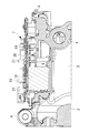
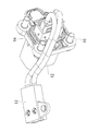
- FIG. 2 is a view corresponding to an aa longitudinal section in FIG. 1. It is a back surface side perspective view of the lid which seals the inverter accommodating part of the above-mentioned inverter integrated electric compressor. It is a perspective view of the power cable simple substance connected to the said cover body. It is a disassembled perspective view which shows the arrangement
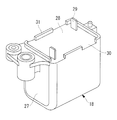
- FIG. 3 is a perspective view of a high voltage system electrical component (smoothing capacitor) disposed at a position facing the PN terminal on the main board.
- FIG. 1 is a perspective view of the main part of an inverter-integrated electric compressor according to an embodiment of the present invention
- FIG. 2 is a corresponding cross-sectional view taken along the line aa
- FIG. FIG. 4 shows a perspective view of a single power cable.
- FIG. The inverter-integrated electric compressor 1 includes a cylindrical housing 2 that forms an outer shell.
- the housing 2 has a structure in which a motor housing 3 for incorporating an electric motor (not shown) and a compressor housing (not shown) for incorporating a compression mechanism (not shown) are integrally coupled.
- an electric motor built in the housing 2 and a compression mechanism are connected via a rotating shaft, and the electric motor is rotationally driven via an inverter device 7 described later.
- the compression mechanism is driven, and the low-pressure refrigerant gas sucked into the interior through the suction port 4 provided on the rear end side surface of the motor housing 3 is sucked through the periphery of the electric motor, and is compressed by the compression mechanism. After being compressed and discharged into the compressor housing, it is sent out to the outside.
- the motor housing 3 is formed with a plurality of refrigerant flow passages 5 for circulating the refrigerant along the axial direction on the inner peripheral surface side, and a plurality of installation leg portions 6 of the electric compressor 1 are formed on the outer peripheral portion thereof. It is provided in the place.
- An inverter housing portion 8 for integrally incorporating the inverter device 7 is integrally formed on the outer peripheral portion of the housing 2 (motor housing 3 side).
- the inverter accommodating portion 8 has a substantially square shape in plan view, the bottom surface is a partially flat base surface 9 formed by the wall surface of the motor housing 3, and a flange portion 10 is raised around the periphery. It has been configured.
- the inverter accommodating portion 8 is configured to be sealed by attaching the lid 11 shown in FIG. 3 to the flange portion 10 after the inverter device 7 is incorporated.
- a high voltage cable (power supply side cable) 12 is provided on the inner surface side of the lid 11.
- the high voltage cable 12 is provided with a connector 13 on one end side and a connector terminal 14 connected to a power supply side cable on the other end side.
- the connector 13 at one end is connected to a main board 20 described later.
- the connector terminal 14 at the other end projects the terminal portion to the outer surface side of the lid body 11. In the state, it is fixedly installed by a plurality of screws 16 from the outer side.
- the high voltage cable 12 forms part of the power supply side cable, and is connected to a power supply unit mounted on the vehicle via the power supply side cable, and a connector 13 provided at one end of the high voltage cable 12 is an inverter device. 7 is connected to the PN terminal 24 provided on the main board 20 to apply high-voltage DC power fed from the power supply unit to the inverter device 7.
- the inverter device 7 converts high-voltage DC power fed from a power supply unit mounted on a vehicle into three-phase AC power having a required frequency, applies it to the electric motor, and drives the electric motor. .
- the inverter device 7 is integrated and incorporated in the inverter housing portion 8, and includes a cased coil 17 and a smoothing that constitute a noise removal filter circuit. It is composed of a plurality of high-voltage system electrical components (hereinafter also simply referred to as electrical components) such as a capacitor 18, a sub board 19, a main board 20, and the like.
- the inverter device 7 itself may be a known one, but here, in order to be integrated, a plurality of electrical components such as a coil 17 and a smoothing capacitor 18 constituting a filter circuit are mounted on the main substrate 20 by soldering. Is used.
- the smoothing capacitor 18 is generally configured to be accommodated in a case. As shown in FIGS. 2 and 6, the outer shape is a square shape (cuboid shape), and the upper surface is a flat shape having a substantially flat shape. Is. Electrical components such as the smoothing capacitor 18 and the cased coil 17 (for example, common mode coil, normal mode coil) are connected to a high voltage line constituted by the wiring pattern of the main board 20 and are known for noise removal.
- a filter circuit is configured.
- the sub circuit board 19 is mounted with a communication circuit 21 connected to a communication line from the host controller, and is mounted on a base surface 9 formed on the wall surface of the motor housing 3 which is the bottom surface of the inverter housing portion 8. It is fixedly installed in contact.
- the sub board 19 is electrically connected to the main board 20.
- the main board 20 is mounted with a switching circuit (not shown) composed of a plurality of switching elements such as IGBTs that convert DC power into three-phase AC power, and a low-power CPU such as a CPU that controls the switching circuit.
- a control circuit 22 that operates on voltage is mounted.
- the main board 20 controls the operation of the inverter device 7 based on a control signal from an ECU mounted on the vehicle side, and is fixedly installed inside the inverter accommodating portion 8 via a plurality of bolts 23. ing.
- the main board 20 has a PN terminal 24 for inputting high-voltage DC power from the high-voltage cable 12 via the connector 13 on the upper surface thereof, and a three-phase AC of a required frequency returned from the DC power.
- a UVW terminal 25 that outputs electric power is provided.
- the UVW terminal 25 is connected to a glass sealed terminal 26 installed in the inverter accommodating portion 8 through the motor housing 3, and the electric motor installed in the motor housing 3 through the glass sealed terminal 26. It is set as the structure which applies three-phase alternating current power to.
- a high voltage line is connected to the PN terminal 24 by inserting the connector 13 provided on the lid 11 side corresponding to the PN terminal 24. Requires a certain pressing force, and the stress is applied to the main board 20.
- a high-voltage electrical component is placed on the back side of the main board 20 so as to face the installation position of the PN terminal 24.
- a smoothing capacitor 18 is provided.
- the smoothing capacitor 18 has a rectangular shape (a rectangular parallelepiped shape) as its outer shape, and is configured to receive stress applied to the main substrate 20 on its upper surface.
- the smoothing capacitor 18 is housed in a resin case 27 whose upper end is opened and is fixed by filling with a resin material 28, and a pair of terminals from the surface of the resin material 28. 29 is protruded, and the terminal 29 is mounted on the main board 20 by being soldered to the main board 20.
- a plurality of concave portions 30 and convex portions 31 are alternately provided at the periphery of the upper end opening that forms the short shape of the case 27 of the smoothing capacitor 18 so that at least one convex portion 31 exists on each side.
- the convex portion 31 here supports the lower surface side portion of the main substrate 20 facing the position where the PN terminal 24 is installed on the upper surface, and the main substrate 20 is inserted when the connector 13 is inserted into the PN terminal 24.
- the smoothing capacitor 18 is manufactured, the recess 30 is caused to escape from the recess 30 when the resin material 28 filled in the case 27 overflows. This is to prevent the dimensional accuracy of the upper surface of the convex portion 31 from being affected.
- the coil 17, which is another high-voltage electrical component is also housed in a resin case 32 having a substantially flat top surface, and is similarly fixed by a resin material.
- the both-end terminals 33 are mounted on the main board 20 by being soldered to the main board 20.
- the coil 17 and the smoothing capacitor 18 are fixed to the main board by fastening the cases 27 and 32 to predetermined positions on the back side of the main board 20 via screws 34 and 35 (see FIG. 1).
- 20 is housed in the inverter housing portion 8 in a state of being integrally assembled with the housing 20, and the bottom portion thereof is fixedly installed on the bottom surface of the inverter housing portion 8 with a silicon adhesive or the like.
- the high voltage system constituting the inverter device 7 is located at the opposite position on the back surface side of the PN terminal 24 provided on the main substrate 20 with the main substrate 20 interposed therebetween. Is provided with a plurality of concave portions 30 and convex portions 31 at the periphery of the upper end opening of the storage case 27 of the smoothing capacitor 18, and the convex portions 31 are formed on the main substrate 20.
- the stress applied to the main board 20 is received when the connector 13 is inserted into the PN terminal 24. Therefore, even when a stress due to an excessive pressing force is applied to the main board 20 when the connector 13 is inserted into the PN terminal 24, the stress can be supported by the smoothing capacitor 18.
- the connector 13 provided at one end of the power supply side cable 12 is inserted into the PN terminal 24 provided on the main board 20, so that the power supply side cable 12 is connected. Even when the connectors are directly connected, the stress applied to the main board 20 when the connector 13 is inserted is arranged at a position opposite to the PN terminal 24 across the main board 20. By receiving it with the smoothing capacitor 18 which is one of the high-voltage electrical parts, it can be greatly reduced.
- a plurality of concave and convex portions are provided at the periphery of the upper end opening of the case 27 that houses the smoothing capacitor 18 that is one of the high-voltage system electrical components, and the convex portion 31 covers the lower surface of the main substrate 20.
- the smoothing capacitor 18 is housed in the case 27 and fixed with the resin material 28, even if the filled resin material 28 overflows, it escapes from the recess 30 and is affected by the resin material 28.
- the dimensional accuracy of the upper surface of the convex portion 31 that supports the main substrate 20 can be maintained, the main substrate 20 can be supported with high accuracy, and the assembly accuracy of the inverter device 7 can be ensured.
- the high-voltage electrical component that receives the stress applied to the main board 20 is the smoothing capacitor 18 that constitutes a noise removal filter circuit provided in the high-voltage DC power line of the inverter device 7.
- the smoothing capacitor 18 housed in the case 27 and having a rectangular outer shape is disposed at a position opposite to the PN terminal 24 with the main substrate 20 interposed therebetween. It can be used as an electrical component that receives the stress applied to the main board 20 as it is.
- a PN provided on the main board 20 is obtained.
- a configuration in which the connector 13 provided at one end of the power supply cable 12 is directly connected to the terminal 24 can be adopted, and the number of parts of the inverter device 7 can be reduced, the cost can be reduced, and the size and weight can be reduced.
- the case 27 of the smoothing capacitor 18 has a rectangular shape in plan view, and a plurality of concave portions 30 and convex portions 31 provided at the periphery of the upper end opening are alternately and at least one convex portion 31 on each side. It is set as the structure provided so that there may exist. For this reason, when the connector 13 is inserted into the PN terminal 24, the stress applied to the main board 20 is dispersed and supported by one or more protrusions 31 provided on each side of the peripheral edge of the rectangular shape of the case 27.
- the smoothing capacitor 18 when it is housed in the case 27 and fixed with the resin material 28, even if the filled resin material 28 overflows, the convex portion that supports the main substrate 20 by escaping from the recess 30. The dimensional accuracy of the upper surface of 31 can be ensured.
- the stress applied to the main board 20 can be greatly relieved, and the main board 20 can be reliably prevented from being damaged and the components mounted thereon can be prevented from being damaged. It is supported with accuracy, and the assembly accuracy of the inverter device 7 can be ensured.
- a connector 13 provided at one end of the power supply side cable 12 is provided at a position corresponding to the PN terminal 24 on the lid 11 side that seals the inverter accommodating portion 8.
- the N terminal 24 can be inserted.
- the side cable 12 can be connected to the PN terminal 24 of the inverter device 7. Therefore, the connection structure of the power supply side cable 12 can be simplified, the connection process can be simplified, and even if the cover body 11 is pushed in with a little excessive force and the connector 13 is fitted, excessive stress is applied to the main board 20. Therefore, the connector 13 can be securely inserted into the PN terminal 24.
- the present invention is not limited to the invention according to the above-described embodiment, and can be modified as appropriate without departing from the scope of the invention.
- the example in which the smoothing capacitor 18 is used as the electrical component disposed on the opposite side of the PN terminal 24 with the main board 20 interposed therebetween is not limited thereto.
- the main substrate 20 may be supported by the case 32 as a coil 17 such as a housed type common mode coil or normal mode coil.
- the case 32 is similar to the case 27 of the smoothing capacitor 18 and the periphery of the upper end opening.
- the high voltage cable 12 is installed in the lid 11 and the power supply side cable is connected thereto.
- the power supply side cable may be composed of one cable. is there.
- the inverter device 7 may have any configuration as long as the PN terminal 24 is provided on the main board 20 and the power supply side cable is connected.
- the inverter device 7 may be integrated into a unit via a resin structure and incorporated in the inverter accommodating portion 8.
Abstract
Description
すなわち、本発明の一態様にかかるインバータ一体型電動圧縮機は、ハウジングの外周に設けられたインバータ収容部に、インバータ装置が組み込まれて一体化されているインバータ一体型電動圧縮機において、インバータ装置のメイン基板上に高電圧の直流電力を入力するP-N端子を設け、該P-N端子にその一端に設けられているコネクタを差し込むことにより電源側ケーブルが接続可能とされているとともに、前記メイン基板を挟んで前記P-N端子と反対側の対向位置に、前記インバータ装置を構成する高電圧系の電装部品が配設され、前記電装部品は、ケース内に収納されて樹脂材で固定された構成とされ、前記ケースの上端開口部の周縁に複数の凹凸部を設け、その凸部を前記メイン基板の下面に当接させることにより、前記コネクタの差し込み時に前記メイン基板にかかる応力を受ける構成とされている。 In order to solve the above-described problems, the inverter-integrated electric compressor of the present invention employs the following means.
That is, an inverter-integrated electric compressor according to an aspect of the present invention is an inverter-integrated electric compressor in which an inverter device is incorporated and integrated in an inverter housing portion provided on the outer periphery of a housing. A PN terminal for inputting high-voltage DC power is provided on the main board, and a power source cable can be connected by inserting a connector provided at one end of the PN terminal. A high-voltage electrical component that constitutes the inverter device is disposed at a position opposite to the PN terminal across the main substrate, and the electrical component is housed in a case and is made of a resin material. The fixed configuration is provided, and a plurality of uneven portions are provided on the periphery of the upper end opening of the case, and the protrusions are brought into contact with the lower surface of the main board, thereby Wherein when insertion of connector is configured to receive the stress applied to the main board.
図1には、本発明の一実施形態の係るインバータ一体型電動圧縮機の主要部の斜視図が示され、図2には、そのa-a縦断面相当図、図3には、インバータ収容部を密閉する蓋体の裏面側斜視図、図4には、電源ケーブル単体の斜視図が示されている。
インバータ一体型電動圧縮機1は、外殻を構成する円筒形状とされたハウジング2を備えている。ハウジング2は、電動モータ(図示省略)を内蔵するためのモータハウジング3と、圧縮機構(図示省略)を内蔵するための圧縮機ハウジング(図示省略)とを一体に結合した構成とされている。 An embodiment according to the present invention will be described below with reference to FIGS.
FIG. 1 is a perspective view of the main part of an inverter-integrated electric compressor according to an embodiment of the present invention, FIG. 2 is a corresponding cross-sectional view taken along the line aa, and FIG. FIG. 4 shows a perspective view of a single power cable. FIG.
The inverter-integrated
P-N端子24には、該P-N端子24と対応して蓋体11側に設けられているコネクタ13が差し込まれることにより、高電圧ラインが接続されるが、コネクタ13を差し込む際には一定以上の押し込み力が必要であり、その応力がメイン基板20にかかるようになっている。 The
A high voltage line is connected to the
2 ハウジング
3 モータハウジング
7 インバータ装置
8 インバータ収容部
11 蓋体
12 高電圧ケーブル(電源側ケーブル)
13 コネクタ
18 平滑コンデンサ(高電圧系の電装部品)
20 メイン基板
24 P-N端子
27 ケース
28 樹脂材
30 凹部
31 凸部 DESCRIPTION OF
13
20
Claims (5)
- ハウジングの外周に設けられたインバータ収容部に、インバータ装置が組み込まれて一体化されているインバータ一体型電動圧縮機において、
インバータ装置のメイン基板上に高電圧の直流電力を入力するP-N端子を設け、該P-N端子にその一端に設けられているコネクタを差し込むことにより電源側ケーブルが接続可能とされているとともに、
前記メイン基板を挟んで前記P-N端子と反対側の対向位置に、前記インバータ装置を構成する高電圧系の電装部品が配設され、
前記電装部品は、ケース内に収納されて樹脂材で固定された構成とされ、前記ケースの上端開口部の周縁に複数の凹凸部を設け、その凸部を前記メイン基板の下面に当接させることにより、前記コネクタの差し込み時に前記メイン基板にかかる応力を受ける構成とされているインバータ一体型電動圧縮機。 In the inverter-integrated electric compressor in which the inverter device is incorporated and integrated in the inverter housing portion provided on the outer periphery of the housing,
A PN terminal for inputting high-voltage DC power is provided on the main board of the inverter device, and a power source cable can be connected by inserting a connector provided at one end of the PN terminal. With
A high-voltage electrical component constituting the inverter device is disposed at a position opposite to the PN terminal across the main board,
The electrical component is housed in a case and fixed with a resin material. A plurality of uneven portions are provided on the periphery of the upper end opening of the case, and the protrusions are in contact with the lower surface of the main board. Thus, an inverter-integrated electric compressor configured to receive stress applied to the main board when the connector is inserted. - 前記電装部品は、前記インバータ装置の高電圧の直流電力ラインに設けられるノイズ除去用のフィルタ回路を構成する平滑コンデンサとされている請求項1に記載のインバータ一体型電動圧縮機。 The inverter-integrated electric compressor according to claim 1, wherein the electrical component is a smoothing capacitor constituting a noise removing filter circuit provided in a high-voltage DC power line of the inverter device.
- 前記電装部品は、前記インバータ装置の高電圧の直流電力ラインに設けられるノイズ除去用のフィルタ回路を構成するコイルとされている請求項1に記載のインバータ一体型電動圧縮機。 2. The inverter-integrated electric compressor according to claim 1, wherein the electrical component is a coil that constitutes a filter circuit for noise removal provided in a high-voltage DC power line of the inverter device.
- 前記電装部品の前記ケースは、平面視が矩形状とされており、その上端開口部の周縁に設けられる複数の前記凹凸部が、交互にかつ各辺に少なくとも1つ以上の凸部が存在するように設けられている1ないし3のいずれかに記載のインバータ一体型電動圧縮機。 The case of the electrical component has a rectangular shape in plan view, and a plurality of the concavo-convex portions provided on the periphery of the upper end opening portion are alternately and have at least one convex portion on each side. The inverter-integrated electric compressor according to any one of 1 to 3, provided as described above.
- 前記電源側ケーブルの一端に設けられている前記コネクタは、前記インバータ収容部を密閉する蓋体側の前記P-N端子と対応する位置に設けられ、前記蓋体の取付け時、前記P-N端子に差し込み可能な構成とされている請求項1ないし4のいずれかに記載のインバータ一体型電動圧縮機。 The connector provided at one end of the power supply side cable is provided at a position corresponding to the PN terminal on the lid side that seals the inverter accommodating portion, and when the lid is attached, the PN terminal The inverter-integrated electric compressor according to claim 1, wherein the inverter-integrated electric compressor is configured to be inserted into the inverter.
Priority Applications (3)
| Application Number | Priority Date | Filing Date | Title |
|---|---|---|---|
| US14/654,995 US9722474B2 (en) | 2013-02-21 | 2013-12-25 | Inverter-integrated electric compressor |
| DE112013006708.0T DE112013006708B4 (en) | 2013-02-21 | 2013-12-25 | Electric compressor with integrated inverter |
| CN201380068086.5A CN104981972B (en) | 2013-02-21 | 2013-12-25 | Inverter-integrated electric compressor |
Applications Claiming Priority (2)
| Application Number | Priority Date | Filing Date | Title |
|---|---|---|---|
| JP2013032185A JP6096003B2 (en) | 2013-02-21 | 2013-02-21 | Inverter-integrated electric compressor |
| JP2013-032185 | 2013-02-21 |
Publications (1)
| Publication Number | Publication Date |
|---|---|
| WO2014129085A1 true WO2014129085A1 (en) | 2014-08-28 |
Family
ID=51390896
Family Applications (1)
| Application Number | Title | Priority Date | Filing Date |
|---|---|---|---|
| PCT/JP2013/084766 WO2014129085A1 (en) | 2013-02-21 | 2013-12-25 | Inverter-integrated electric compressor |
Country Status (5)
| Country | Link |
|---|---|
| US (1) | US9722474B2 (en) |
| JP (1) | JP6096003B2 (en) |
| CN (1) | CN104981972B (en) |
| DE (1) | DE112013006708B4 (en) |
| WO (1) | WO2014129085A1 (en) |
Families Citing this family (7)
| Publication number | Priority date | Publication date | Assignee | Title |
|---|---|---|---|---|
| JP6153745B2 (en) * | 2013-03-07 | 2017-06-28 | 三菱重工オートモーティブサーマルシステムズ株式会社 | Inverter board and inverter-integrated electric compressor using the same |
| JP6516357B2 (en) * | 2015-04-20 | 2019-05-22 | 三菱重工サーマルシステムズ株式会社 | Circuit board for electric power conversion and electric compressor |
| JP6700674B2 (en) * | 2015-05-21 | 2020-05-27 | 三菱重工サーマルシステムズ株式会社 | Motor housing for electric compressor and vehicle-mounted electric compressor using the same |
| FR3050887B1 (en) * | 2016-04-28 | 2018-04-27 | Valeo Systemes De Controle Moteur | ELECTRONIC FILTER FOR FILTERING THE POWER SUPPLY POWER OF AN ELECTRIC MOTOR |
| DE102017111396B4 (en) * | 2017-05-24 | 2020-08-06 | Hanon Systems | Arrangement for the active suppression of interference signals |
| CN107476951B (en) * | 2017-08-08 | 2019-03-22 | 中山大洋电机股份有限公司 | Integrated electric air compressor and the fuel battery air gas handling system for applying it |
| JP6976881B2 (en) * | 2018-02-23 | 2021-12-08 | サンデン・オートモーティブコンポーネント株式会社 | Electric compressor |
Citations (4)
| Publication number | Priority date | Publication date | Assignee | Title |
|---|---|---|---|---|
| JPH0613539A (en) * | 1992-06-26 | 1994-01-21 | Fuji Electric Co Ltd | Semiconductor device |
| JPH11135965A (en) * | 1997-10-30 | 1999-05-21 | Nippon Seiki Co Ltd | Retaining structure of printed substrate with connector |
| JP2000261160A (en) * | 1999-03-12 | 2000-09-22 | Harness Syst Tech Res Ltd | Branch connection box |
| JP2012209414A (en) * | 2011-03-29 | 2012-10-25 | Mitsubishi Heavy Ind Ltd | Electronic substrate and inverter-integrated electric compressor |
Family Cites Families (17)
| Publication number | Priority date | Publication date | Assignee | Title |
|---|---|---|---|---|
| JPS5927563A (en) * | 1982-08-07 | 1984-02-14 | Mitsubishi Electric Corp | Semiconductor device |
| JPH0613639A (en) | 1992-06-24 | 1994-01-21 | Sanyo Electric Co Ltd | Photovoltaic device |
| US6954368B1 (en) * | 1996-07-22 | 2005-10-11 | HYDRO-QUéBEC | Low stray interconnection inductance power converting molecule for converting a DC voltage into an AC voltage, and a method therefor |
| JP4162523B2 (en) * | 2002-06-03 | 2008-10-08 | シャープ株式会社 | Inverter |
| JP2007295639A (en) | 2006-04-20 | 2007-11-08 | Denso Corp | Motor drive for vehicle |
| JP4867889B2 (en) | 2007-01-18 | 2012-02-01 | 株式会社デンソー | Power converter and manufacturing method thereof |
| JP5144945B2 (en) * | 2007-03-06 | 2013-02-13 | 三菱重工業株式会社 | Integrated electric compressor |
| JP5138551B2 (en) | 2008-11-06 | 2013-02-06 | サンデン株式会社 | Inverter-integrated electric compressor |
| JP5120240B2 (en) | 2008-12-22 | 2013-01-16 | 株式会社豊田自動織機 | Electric compressor |
| JP5152701B2 (en) | 2009-05-18 | 2013-02-27 | 住友電気工業株式会社 | Reactor, coil molding, and converter |
| CN101707433A (en) * | 2009-11-11 | 2010-05-12 | 中国科学院电工研究所 | Insulated gate bipolar transistor on-vehicle traction converter |
| JP5450042B2 (en) * | 2009-12-25 | 2014-03-26 | 日立オートモティブシステムズ株式会社 | Actuator control device |
| JP4832581B2 (en) * | 2010-01-29 | 2011-12-07 | トヨタ自動車株式会社 | Terminal block for rotating electrical machines |
| JP4898931B2 (en) | 2010-02-10 | 2012-03-21 | 三菱重工業株式会社 | Inverter-integrated electric compressor |
| JP5067679B2 (en) * | 2010-05-21 | 2012-11-07 | 株式会社デンソー | Semiconductor module and driving device using the same |
| JP5338804B2 (en) * | 2010-12-28 | 2013-11-13 | 株式会社デンソー | DRIVE DEVICE AND ELECTRIC POWER STEERING DEVICE USING THE SAME |
| JP5382036B2 (en) * | 2011-03-16 | 2014-01-08 | 株式会社豊田自動織機 | Electric compressor |
-
2013
- 2013-02-21 JP JP2013032185A patent/JP6096003B2/en active Active
- 2013-12-25 DE DE112013006708.0T patent/DE112013006708B4/en active Active
- 2013-12-25 US US14/654,995 patent/US9722474B2/en active Active
- 2013-12-25 WO PCT/JP2013/084766 patent/WO2014129085A1/en active Application Filing
- 2013-12-25 CN CN201380068086.5A patent/CN104981972B/en active Active
Patent Citations (4)
| Publication number | Priority date | Publication date | Assignee | Title |
|---|---|---|---|---|
| JPH0613539A (en) * | 1992-06-26 | 1994-01-21 | Fuji Electric Co Ltd | Semiconductor device |
| JPH11135965A (en) * | 1997-10-30 | 1999-05-21 | Nippon Seiki Co Ltd | Retaining structure of printed substrate with connector |
| JP2000261160A (en) * | 1999-03-12 | 2000-09-22 | Harness Syst Tech Res Ltd | Branch connection box |
| JP2012209414A (en) * | 2011-03-29 | 2012-10-25 | Mitsubishi Heavy Ind Ltd | Electronic substrate and inverter-integrated electric compressor |
Also Published As
| Publication number | Publication date |
|---|---|
| JP6096003B2 (en) | 2017-03-15 |
| CN104981972B (en) | 2017-12-12 |
| DE112013006708T5 (en) | 2015-10-29 |
| DE112013006708B4 (en) | 2023-07-27 |
| US20150349613A1 (en) | 2015-12-03 |
| US9722474B2 (en) | 2017-08-01 |
| CN104981972A (en) | 2015-10-14 |
| JP2014165944A (en) | 2014-09-08 |
Similar Documents
| Publication | Publication Date | Title |
|---|---|---|
| WO2014129085A1 (en) | Inverter-integrated electric compressor | |
| JP6029484B2 (en) | Inverter-integrated electric compressor | |
| US10008895B2 (en) | Inverter-integrated electric compressor | |
| JP5511232B2 (en) | Inverter module and inverter-integrated electric compressor using the same | |
| US10253763B2 (en) | Motor-driven compressor | |
| JP6037809B2 (en) | Inverter-integrated electric compressor | |
| US10122237B2 (en) | Inverter circuit board and inverter-containing electric compressor using same | |
| JP6021623B2 (en) | Inverter-integrated electric compressor | |
| JP6195453B2 (en) | Inverter-integrated electric compressor | |
| US9929618B2 (en) | Inverter-integrated electric compressor | |
| CN108369863B (en) | Power conversion device | |
| JP2012200070A (en) | Driving control device of electric actuator | |
| WO2020179404A1 (en) | Electric compressor | |
| JP5574794B2 (en) | Inverter-integrated electric compressor | |
| WO2017221854A1 (en) | Electrical component mounting structure and inverter-integrated electric compressor including the same | |
| JP6102704B2 (en) | Motor drive device |
Legal Events
| Date | Code | Title | Description |
|---|---|---|---|
| 121 | Ep: the epo has been informed by wipo that ep was designated in this application |
Ref document number: 13875410 Country of ref document: EP Kind code of ref document: A1 |
|
| WWE | Wipo information: entry into national phase |
Ref document number: 14654995 Country of ref document: US |
|
| WWE | Wipo information: entry into national phase |
Ref document number: 1120130067080 Country of ref document: DE Ref document number: 112013006708 Country of ref document: DE |
|
| 122 | Ep: pct application non-entry in european phase |
Ref document number: 13875410 Country of ref document: EP Kind code of ref document: A1 |