WO2014123204A1 - Load application device - Google Patents
Load application device Download PDFInfo
- Publication number
- WO2014123204A1 WO2014123204A1 PCT/JP2014/052810 JP2014052810W WO2014123204A1 WO 2014123204 A1 WO2014123204 A1 WO 2014123204A1 JP 2014052810 W JP2014052810 W JP 2014052810W WO 2014123204 A1 WO2014123204 A1 WO 2014123204A1
- Authority
- WO
- WIPO (PCT)
- Prior art keywords
- spring
- applying device
- load applying
- mainspring
- load
- Prior art date
Links
Images


Classifications
-
- F—MECHANICAL ENGINEERING; LIGHTING; HEATING; WEAPONS; BLASTING
- F16—ENGINEERING ELEMENTS AND UNITS; GENERAL MEASURES FOR PRODUCING AND MAINTAINING EFFECTIVE FUNCTIONING OF MACHINES OR INSTALLATIONS; THERMAL INSULATION IN GENERAL
- F16H—GEARING
- F16H7/00—Gearings for conveying rotary motion by endless flexible members
- F16H7/08—Means for varying tension of belts, ropes, or chains
-
- F—MECHANICAL ENGINEERING; LIGHTING; HEATING; WEAPONS; BLASTING
- F01—MACHINES OR ENGINES IN GENERAL; ENGINE PLANTS IN GENERAL; STEAM ENGINES
- F01L—CYCLICALLY OPERATING VALVES FOR MACHINES OR ENGINES
- F01L1/00—Valve-gear or valve arrangements, e.g. lift-valve gear
- F01L1/12—Transmitting gear between valve drive and valve
- F01L1/18—Rocking arms or levers
-
- F—MECHANICAL ENGINEERING; LIGHTING; HEATING; WEAPONS; BLASTING
- F16—ENGINEERING ELEMENTS AND UNITS; GENERAL MEASURES FOR PRODUCING AND MAINTAINING EFFECTIVE FUNCTIONING OF MACHINES OR INSTALLATIONS; THERMAL INSULATION IN GENERAL
- F16H—GEARING
- F16H7/00—Gearings for conveying rotary motion by endless flexible members
- F16H7/08—Means for varying tension of belts, ropes, or chains
- F16H2007/0802—Actuators for final output members
- F16H2007/0804—Leaf springs
-
- F—MECHANICAL ENGINEERING; LIGHTING; HEATING; WEAPONS; BLASTING
- F16—ENGINEERING ELEMENTS AND UNITS; GENERAL MEASURES FOR PRODUCING AND MAINTAINING EFFECTIVE FUNCTIONING OF MACHINES OR INSTALLATIONS; THERMAL INSULATION IN GENERAL
- F16H—GEARING
- F16H7/00—Gearings for conveying rotary motion by endless flexible members
- F16H7/08—Means for varying tension of belts, ropes, or chains
- F16H2007/0802—Actuators for final output members
- F16H2007/081—Torsion springs
-
- F—MECHANICAL ENGINEERING; LIGHTING; HEATING; WEAPONS; BLASTING
- F16—ENGINEERING ELEMENTS AND UNITS; GENERAL MEASURES FOR PRODUCING AND MAINTAINING EFFECTIVE FUNCTIONING OF MACHINES OR INSTALLATIONS; THERMAL INSULATION IN GENERAL
- F16H—GEARING
- F16H7/00—Gearings for conveying rotary motion by endless flexible members
- F16H7/08—Means for varying tension of belts, ropes, or chains
- F16H2007/0889—Path of movement of the finally actuated member
- F16H2007/0893—Circular path
Definitions
- the present invention relates to a load applying device such as a tensioner used to keep the tension of an endless belt or chain constant.
- a tensioner as one of the load application devices presses a timing chain or timing belt used in an automobile engine with a predetermined force, and keeps the tension constant when it is stretched or loosened. Acts as follows.
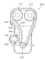
- FIG. 31 shows the inside of the engine body 200 of the automobile.
- a pair of cam sprockets 210 and 210 that are driven shafts and a crank sprocket 220 that is a drive shaft are disposed inside the engine body 200, and the timing chain 230 is endless between these sprockets 210, 210, and 220. It is stretched over in a shape.
- the timing chain 230 moves (runs) between the sprockets 210, 210, and 220 by the rotation of the crank sprocket 220.
- a chain guide 240 is disposed on the moving path of the timing chain 230 so as to contact the timing chain 230, and the timing chain 230 moves while sliding on the chain guide 240.
- the chain guide 240 can swing around the support shaft 250, and the tension of the timing chain 230 is adjusted by this swing.
- Numeral 300 is a tensioner provided inside the engine main body 200 for pressing the chain guide 240 against the timing chain 230.
- the tensioner 300 generally has a structure that presses the chain guide 240 by expansion and contraction in the axial direction.
- the tensioner 300 includes a case 310 fixed in the engine main body 200 and a propulsion shaft 320 disposed in the case 310 so as to be movable forward and backward.
- the propulsion shaft 320 is urged so as to advance from the case 310 by a coil spring (not shown) provided inside the case 310.
- the tip of the propulsion shaft 320 is in contact with the chain guide 240 and applies tension to the timing chain 230 by pressing the chain guide 240.
- a tensioner 300 shown in FIG. 31 has a structure in which a coil spring and a propulsion shaft 320 are arranged in a case 310, and the propulsion shaft 320 advances and retreats in the axial direction, so that it becomes longer in the axial direction and shortened in the axial direction.
- a tensioner using a spring spring has been developed (see Patent Documents 1 and 2).
- the tensioner of Patent Document 1 includes a cam member made of an eccentric cam that swings the chain guide in a direction in which the timing chain is tensioned, and a spring spring that biases the cam member to swing in a direction in which the chain guide is pressed. It has a prepared structure. The cam member is prevented from being reversely rotated by meshing the reverse rotation preventing claw. The spring spring has an inner end that is locked to a fixing pin of the engine body, and an outer end that is locked to a cam member. The chain guide is pressed by swinging.
- the tensioner of Patent Document 2 also uses a mainspring spring and a cam member, but the cam member has a structure in which a cam surface having an involute curve is formed. Further, a rolling bearing is attached to the chain guide, and the rolling bearing is in contact with the cam surface of the cam member so as to be able to roll. For this reason, when the cam member swings, the rolling bearing rolls on the cam surface.
- the spring spring has its outer end locked to the engine body, and its inner end locked to the cam member to urge the cam member so that the cam member swings and presses the tune guide. Yes.
- the cam member connected to the mainspring spring is in contact with the chain guide and swings so as to apply the tension of the timing chain, and moves forward and backward in the axial direction. Therefore, the axial direction can be shortened.
- an object of the present invention is to provide a load application device such as a tensioner that has a large vibration damping force, can suppress the generation of a hitting sound, and has a simple structure even if the structure uses a spring spring.
- the mainspring spring in which the thin plate material is wound a plurality of times is disposed between the movable body and the fixed member, and the outer periphery of the mainspring spring is separated from the movable body and the fixed member.
- the outer periphery of the mainspring spring is in direct contact with the movable body or indirectly through an indirect member so as to receive a load.
- the invention according to claim 2 is the load applying device according to claim 1, wherein the outer peripheral portion of the mainspring spring comes into contact with each of the fixing member and the indirect member at least in two places due to the diameter expansion of the mainspring spring. It is characterized by that.
- a third aspect of the present invention is the load applying apparatus according to the first or second aspect, wherein the fixing member and the indirect member have triangular, arc-shaped or linear receiving portions facing the outer peripheral portion of the mainspring spring. Is formed.
- a fourth aspect of the present invention is the load applying device according to any one of the first to third aspects, wherein a buffer member is provided between an outer peripheral portion of the mainspring spring and at least one of the indirect member or the fixing member. It is arranged.
- a fifth aspect of the present invention is the load applying device according to any one of the first to third aspects, wherein the deformation is deformed between an outer peripheral portion of the mainspring spring and at least one of the indirect member or the fixing member. And the plate-shaped elastic member which contacts the said indirect member or the said fixing member is arrange
- a sixth aspect of the present invention is the load applying device according to any one of the first to third aspects, wherein the mainspring spring is arranged in a direction of a load from the movable body between the fixed member and the indirect member.
- a plurality of the springs are provided side by side, and an intermediate member is disposed between adjacent springs.
- the invention according to claim 7 is the load applying device according to claim 5, wherein the plate-like elastic member has both end portions in the length direction in contact with the fixing member or the indirect member, and an intermediate portion in the length direction. It has the space which can bend and deform
- the invention according to claim 8 is the load applying device according to claim 6, wherein the plurality of side-by-side springs are continuous with thin plate members between the springs.
- a ninth aspect of the present invention is the load applying device according to any one of the first to third aspects or the sixth aspect, wherein the fixed member or the intermediate member intersects the direction of the load from the movable body. It consists of the divided
- a tenth aspect of the present invention is the load applying apparatus according to the fourth aspect, wherein an uneven portion is formed in a portion of the buffer member facing the outer peripheral portion of the mainspring spring.
- the invention of claim 11 is the load applying device according to any one of claims 1 to 9, wherein the indirect member covers the outer periphery of the mainspring spring in the circumferential direction in the direction of the movable body. It is a propulsion member that can move forward and backward.
- a twelfth aspect of the present invention is the load applying device according to any one of the first to eleventh aspects, wherein an adjustment mechanism in a length direction is interposed between the fixed member and the movable body. To do.
- a thirteenth aspect of the present invention is the load applying device according to any one of the first to ninth aspects, wherein the indirect member is a guide member that contacts the movable body in a swingable state. To do.
- a fourteenth aspect of the present invention is the load applying device according to any one of the first to thirteenth aspects, wherein hydraulic pressure can be supplied to the inside of the inner peripheral portion of the mainspring spring.
- a fifteenth aspect of the invention is the load applying device according to any one of the first to fourteenth aspects, characterized in that provisional fastening means for holding the mainspring spring in a wound state is provided. .
- a sixteenth aspect of the present invention is the load applying device according to any one of the first to fifteenth aspects, wherein the movable body is a timing chain or a timing belt that moves endlessly in an automobile engine. It is characterized by that.
- the invention according to claim 17 is the load applying device according to any one of claims 1 to 15, wherein the movable body is a rocker arm that swings to open and close an intake valve of an automobile engine. It is characterized by.
- the outer peripheral portion of the mainspring spring is in direct contact with the movable body or indirectly through the indirect member, and the movable body is pressed by this contact, so the number of parts is reduced and the structure is simplified. .
- the rigidity is lowered, the buffering force for damping the vibration is large, and the occurrence of hitting sound can be suppressed.
- FIG. 5 is a cross-sectional view taken along the line aa of FIG. 4 after winding the mainspring spring. It is a side view explaining the effect
- FIG. 4 is a deflection-load diagram of a spring.
- FIG. 1 It is a side view which shows the deformation state of the tensioner of 1st Embodiment.
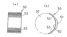
- the cylindrical body for winding used for the tensioner of a deformation state is shown, (a) is a side view, (b) is a front view.
- the tensioner of 2nd Embodiment as a load addition apparatus of this invention is shown, (a) is a side view which shows the state which wound up the mainspring spring, (b) is a front view. It is a side view which shows the state which the mainspring spring in the tensioner of 2nd Embodiment expanded.
- the 1st case part used for the tensioner of 2nd Embodiment is shown, (a) is a side view, (b) is a front view, (c) is a bb sectional view taken on the line.
- the 2nd case part used for the tensioner of 2nd Embodiment is shown, (a) is a side view, (b) is a front view, (c) is a cc sectional view.
- a propulsion member is shown, (a) is a side view, (b) is a front view.
- (A)-(d) is a side view explaining the effect
- the buffer member used for the tensioner of 3rd Embodiment is shown, (a) is a rear view, (b) is a side view.
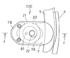
- the tensioner of 4th Embodiment as a load addition apparatus of this invention is shown, (a) is the dd sectional view taken on the line of (b), (b) is a front view.
- FIG. 22 is a sectional view taken along line ff in FIG. 21.
- FIG. 1 It is sectional drawing which shows the state which attached the tensioner of 7th Embodiment as a load addition apparatus of this invention to the engine main body.
- the tensioner of 8th Embodiment as a load addition apparatus of this invention is shown, (a) is a side view, (b) is a front view.
- (A)-(d) is a side view explaining the effect
- the tensioner of 9th Embodiment as a load addition apparatus of this invention is shown, (a) is the j sectional view taken on the line of (b), (b) is a front view.
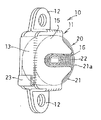
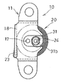
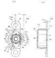
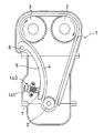
- (First embodiment) 1 to 7 show a first embodiment of a tensioner 10 used as one of the load applying devices of the present invention.
- FIG. 1 shows an engine body 1 provided with a tensioner 10, which is provided with a crank sprocket 2 as a drive shaft and two cam sprockets 3 as a driven shaft, and a timing chain as a movable body between these sprockets 2 and 3. 4 is stretched endlessly.
- the timing chain 4 moves (runs) between the sprockets 2, 3 and 3 by the rotation of the crank sprocket 2.
- a chain guide 5 as a guide member is disposed on the moving path of the timing chain 4 so as to contact the timing chain 4, and the timing chain 4 moves while sliding the chain guide 5.
- the chain guide 5 can swing around the support shaft 6, and the tension of the timing chain 4 is adjusted by this swing.
- the tensioner 10 is provided inside the engine body 1 so as to face the chain guide 5 and applies tension to the timing chain 4 by pressing the chain guide 5 and swinging the chain guide 5.
- the tensioner 10 includes a spring 20 as will be described later.
- the chain guide 5 as a guide member constitutes an indirect member in which the outer peripheral portion of the mainspring spring 20 abuts on the timing chain (movable body) 4 indirectly.
- the timing chain 4 receives torque fluctuation by rotating the cam sprocket 3 (cam shaft), and moves while changing tension. For this reason, the tensioner 10 receives vibration (alternate load) from the timing chain 4 and the chain guide 5.
- a housing portion 13 is formed by a bottom plate portion 14 and a top plate portion 15, and a spring 20 is housed in the housing portion 13.
- a flange portion 12 extending in the vertical direction is formed in the case 11, and a tensioner 10 is fixed inside the engine body 1 by attaching a bolt or the like to the flange portion 12.
- the mainspring 20 is formed by spirally winding a thin plate material having spring properties, and is housed in the housing portion 13 for use. In the housed state in the case 11, the spring spring 20 is sandwiched between the bottom plate portion 14 and the top plate portion 15 from both sides in the plate width direction of the thin plate material. As a result, the mainspring spring 20 is accommodated in the case 11 in a state where the thin plate material does not shift in the plate width direction (a state where the thin plate material does not move out). Further, the case 11 is provided with a spring receiving portion (receiving portion) 18 with which the outer peripheral portion 21 of the mainspring spring 20 contacts (see FIGS. 3, 4, and 6). In this embodiment, the spring receiving portion 18 is formed in a planar shape (linear shape), and the spring 21 is supported by the case 11 by the outer peripheral portion 21 coming into contact with the linear spring receiving portion (receiving portion) 18. Is done.
- the outer periphery 21 of the mainspring spring 20 is partially exposed from the case 11.
- Reference numeral 21a denotes an exposed portion of the outer peripheral portion 21 of the mainspring spring 20, and the exposed portion 21a directly contacts the receiving portion 7 on the chain guide 5 side (see FIG. 6). Due to the direct contact with the receiving portion 7, the mainspring spring 20 can directly exert an urging force for the chain guide 5 to swing on the chain guide 5. Further, vibration from the chain guide 5 is directly input to the mainspring spring 20.
- the mainspring 20 is a winding portion 22 in which an inner end portion wound in a spiral shape is formed in a hexagonal shape, and an outer end portion becomes an outer end locking portion 23 that is hooked and locked by the case 11. ing.
- the winding part 22 is exposed from the notch part 16 formed in the top plate part 15 of the case 11, and a winding member 30 such as a hexagon wrench can be inserted into the winding part 22 through the notch part 16 ( 4 and 5). Thereby, the winding spring 30 can be wound up (reduced in diameter) by operating the winding member 30.
- the bottom plate portion 14 of the case 11 is formed with a hexagonal temporary fixing hole 17 in which the leading end of the winding member 30 is locked when the leading end of the winding member 30 is inserted.
- a temporary fixing hole 17 constitutes a temporary fixing means for holding the mainspring spring 20 in a wound state.
- the winding portion 22 of the mainspring 20 and the temporary fixing hole 17 of the case 11 are formed in a non-circular shape that matches the outer shape of the winding member 30, and the outer shape of the winding member 30 has a triangular cross section and a square cross section. In some cases, it is formed in a non-circular shape to match these.
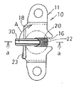
- the tensioner 10 of this embodiment Before fixing to the engine body 1, the winding member 30 is inserted into the winding portion 22 of the mainspring 20 and rotated in the winding direction A shown in FIG. As a result, the mainspring 20 is wound up and reduced in diameter, and the spring force is stored. After the mainspring spring 20 is reduced in diameter, the tip of the winding member 30 is locked in the temporary fixing hole 17 of the case 11 as shown in FIG. Thus, the tensioner 10 is temporarily fixed in a state where the mainspring 20 is wound up. Thereafter, the tensioner 10 is attached to the engine body 1. By this attachment, the exposed portion 21 a of the outer peripheral portion 21 of the mainspring spring 20 faces the receiving portion 7 of the chain guide 5.
- the winding member 30 is pulled out. Thereby, the mainspring spring 20 is expanded in diameter by the stored spring force. Due to the diameter expansion, the outer peripheral portion 21 of the mainspring spring 20 contacts the spring receiving portion 18 of the case 11 and the receiving portion 7 of the chain guide 5. Due to this contact, the spring 20 receives the load from the timing chain 4 and the load (supporting force) of the case 11. Since the spring spring 20 has the outer peripheral portion 21 received by the spring receiving portion 18, the exposed portion 21 a of the outer peripheral portion 21 pushes the chain guide 5 and swings the chain guide 5 due to the expanded diameter. Therefore, tension can be applied to the timing chain 4 via the chain guide 5.
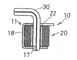
- FIG. 6 shows a state in which the mainspring spring 20 receives a load from the chain guide 5 by contacting the chain guide 5.
- the spring 20 is sandwiched between the receiving portion 7 of the chain guide 5 and the spring receiving portion (receiving portion) 18 of the case 11, and an alternating load (vibration) indicated by an arrow B acting from the chain guide 5 is applied to the chain guide. Receive from 5.
- the exposed portion 21a bends in the direction of the arrow B while the spring 20 is swollen in the direction of the arrow C by this alternating load. Since the spring 20 is a member obtained by winding a thin plate material having a spring property in a spiral shape, it can be a spring of overlapping thin plate materials and can withstand a strong alternating load.
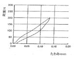
- FIG. 7 shows a deflection-load diagram of the mainspring spring 20 when a static load is applied to the outer peripheral portion 21 of the mainspring spring 20.
- the mainspring 20 is a member obtained by winding a thin plate material a plurality of times, and friction occurs between the thin plate materials when a load is applied.
- the tensioner 10 that receives the alternating load (vibration) in the direction of arrow B from the chain guide 5 is pressed in the direction of arrow B and exerts a large force.
- the force is small. A large difference is generated between the arrow B direction and the direction opposite to the B direction due to the difference in the magnitude of the force (hist properties).
- This hysteresis characteristic can absorb the alternating load (vibration) received from the chain guide 5, so that the buffering force for damping the vibration can be increased.
- the elastic member having a small hysteresis characteristic such as a compression coil spring, is used instead of the mainspring spring, the difference in force between the B direction and the B direction is very small. It is difficult to absorb the alternating load (vibration).
- the mainspring 20 is formed by a plurality of windings of a thin plate material, it has low rigidity unlike a solid member, and thus has a silent effect for suppressing the hitting sound.
- the mainspring spring 20 follows this and expands in a stepless manner. Since the outer peripheral portion 21 presses the chain guide 5 by this diameter expansion, the tensioned state of the timing chain 4 can be adjusted steplessly.
- the spring 20 is formed of a thin plate material, the inter-plate friction generated between the thin plates when the main spring 20 expands in diameter is large. For this reason, the load at the time of diameter expansion becomes small. Moreover, since the diameter expansion speed becomes slow, instantaneous excessive tension can be reduced. As a result, the chain guide 5 is softly pressed, so that the tension of the timing chain 4 does not increase more than necessary.
- the timing chain 4 is tensed, the spring 20 is bent as described with reference to FIG.
- the tensioner 10 can be reduced in size and a dedicated space for installation can be reduced. Further, the number of parts as the tensioner 10 is small, and the structure becomes simple.
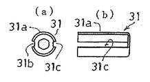
- FIG. 8 shows a modified tensioner 10 of this embodiment.
- a winding cylinder 31 is provided at the inner end of the spring 20.
- the winding cylinder 31 includes a cylinder body 31a formed to have a length substantially the same as the plate width of the thin plate member of the mainspring spring 20, and a hexagonal winding formed in the central portion of the cylinder body 31a. It is formed by the hole 31b and the latching recessed part 31c formed along the length direction in the outer surface of the cylinder main body 31a.
- the winding cylinder 31 is inserted into the inner end of the mainspring spring 20, and the inner end locking portion 24 of the mainspring spring 20 is locked to the locking recess 31c to be connected to the mainspring spring 20. Then, a winding member 30 such as a hexagon wrench is inserted into the winding hole 31b of the winding cylinder 31 and rotated. As a result, the mainspring 20 can be wound up and spring force can be stored in the mainspring 20. After the mainspring 20 is wound up, the mainspring 20 can be temporarily fixed in a state where the spring force is stored by engaging the tip of the winding member 30 in the temporary fixing hole 17 of the case 11. By providing the winding cylinder 31 which is a separate member from the mainspring 20 in this way, the inner spring end of the mainspring 20 is not required, so that the mainspring 20 can be easily manufactured.
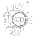
- (Second Embodiment) 10 to 15 show a tensioner 10A according to a second embodiment used as a load applying device of the present invention.
- the tensioner 10A incorporates a propelling member 40 in addition to the case 11 and the spring 20 of the tensioner 1 of the first embodiment.
- the propulsion member 40 covers the exposed portion 21 a in the outer peripheral portion 21 of the mainspring spring 20 in the circumferential direction. Move forward and backward.
- the propelling member 40 is provided between the outer peripheral portion 21 of the spring 20 and the chain guide 5 by covering the outer peripheral portion 21 of the mainspring spring 20.
- the propelling member 40 constitutes an indirect member in which the outer peripheral portion 21 of the mainspring 20 indirectly contacts the timing chain (movable body) 4.
- FIG. 14 shows the propelling member 40, which is formed of a plate material having a width substantially similar to the plate width of the thin plate material of the mainspring spring 20.
- the propulsion member 40 includes a cover portion 41 that covers the exposed portion 21a of the outer peripheral portion 21 of the spring 20, a guide portion 42 that extends linearly from both ends of the cover portion 41 and extends away from the chain guide 5, and a guide The stopper portion 43 is formed at the end of the portion 42.
- the cover portion 41 has a shape in which two oblique straight portions 41b are continuous from both sides of the arc portion 41a with the arc portion 41a in the middle.
- the two oblique straight portions 41b extend obliquely away from each other from the arc portion 41a.
- the cover portion 41 including the arc portion 41 a and the oblique straight portion 41 b contacts the outer peripheral portion 21 of the mainspring spring 20 from the reduced diameter state to the expanded diameter state of the mainspring spring 20. That is, when the spring spring 20 is in the reduced diameter state, the exposed portion 21a of the outer peripheral portion 21 of the mainspring spring 20 abuts on the arc portion 41a of the cover portion 41 (see FIG.
- the cover portion 41 is slanted.
- the outer peripheral part 21 of the mainspring 20 contacts the straight part 41b (see FIG. 11).
- Such a covering portion 41 constitutes a receiving portion that faces the outer peripheral portion 21 of the mainspring spring 20 and receives the outer peripheral portion 21 of the spring 20.
- the circular arc part 41a of the cover part 41 becomes an arc shape and receives the outer peripheral part 21 of the mainspring spring 20, and the two oblique straight parts 41b on both sides of the arc part 41a become triangular and the outer peripheral part of the mainspring spring 20 21.
- the guide portion 42 of the propulsion member 40 slides on the case 11 when the propulsion member 40 moves forward and backward, and thereby the forward and backward movement of the propulsion member 40 is stabilized.
- the stopper portion 43 is locked to the case 11 by the advancement of the propulsion member 40, thereby restricting the advancement of the propulsion member 40 within a predetermined range and preventing the propulsion member 40 from coming off the case 11.
- the first case portion 11a forming the case 11 as a fixing member is shown in FIG. 12, and the second case portion 11b is shown in FIG.
- the first case portion 11 a is formed by a plate-like flange portion 70 and a spring receiving portion (receiving portion) 71 that rises integrally from a substantially central portion in the length direction of the flange portion 70.
- the flange part 70 is a part for assembling with the second case part 11b, and a temporary fixing hole 17 made of a hexagonal hole in which the winding member 30 is locked is formed.
- the spring receiving portion (receiving portion) 71 rises from the flange portion 70 so as to correspond to the outer peripheral portion 21 of the mainspring spring 20.
- the height of the spring receiving portion 71 is substantially the same as the plate width of the thin plate material of the mainspring spring 20.
- the spring receiving portion 71 has a shape in which two oblique straight portions 71b are continuous from both sides of the arc portion 71a with the arc portion 71a in the middle.
- the two oblique straight portions 71b are in an oblique state and extend in an oblique direction away from both sides of the arc portion 71a.
- Such a spring receiving portion 71 is in contact with the outer peripheral portion 21 of the mainspring spring 20 from the mainspring spring 20 from the reduced diameter state to the expanded diameter state.
- the exposed portion 21a in the outer peripheral portion 21 comes into contact (see FIG. 10), and the outer peripheral portion 21 of the mainspring spring 20 comes into contact with the oblique straight portion 71b in the expanded state of the mainspring spring 20 (see FIG.
- the arc portion 71a of the receiving portion 71 has an arc shape like the arc portion 41a of the cover portion 41 of the propelling member 40 and receives the outer peripheral portion 21 of the mainspring spring 20, and two oblique straight lines on both sides of the arc portion 71a.
- the part 71b is triangular and receives the outer peripheral part 21 of the spring 20.
- the second case portion 11 b includes flat flange portions 73 on both sides in the length direction, and rising portions that rise from the respective flange portions 73 at substantially the same height as the plate width of the thin plate member of the spring spring 20. 74 and a top plate portion 75 that connects the rising portions 74.
- the top plate part 75 covers the upper part of the mainspring spring 20, and a notch part 16 through which the winding member 30 is inserted is formed.
- the rising portion 74 is a portion on which the guide portion 42 of the propelling member 40 slides, and the propelling member 40 moves forward and backward stably by this sliding.
- the mainspring 20 is arranged in a space surrounded by the spring receiving portion 71 of the case 11 and the propelling member 40.
- the winding member 30 is inserted into the winding portion 22 of the mainspring spring 20 and rotated in the winding direction, whereby the mainspring spring 20 is wound and reduced in diameter.
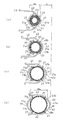
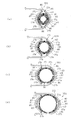
- FIG. 10 shows a state in which the mainspring 20 is wound up, and the outer peripheral portion 21 of the mainspring 20 contacts the arc portion 71a of the spring receiving portion 71 of the case 11 and the arc portion 41a of the cover portion 41 of the propelling member 40 (FIG. 15). (See (a)).
- the triangular marks in FIGS. 15A to 15D indicate the contact portions 27 on the outer peripheral portion 21 of the mainspring spring 20.
- the diameter of the mainspring 20 is increased by the spring force accumulated.
- the outer peripheral portion 21 of the mainspring spring 20 contacts the spring receiving portion 71 of the case 11 at two locations and contacts the propulsion member 40 at two locations. That is, the outer peripheral portion 21 of the spring 20 is in contact with the respective oblique straight portions 71b of the spring receiving portion 71 and the respective oblique straight portions 41b in the covering portion 41 of the propelling member 40 as shown in FIG.
- FIG. 15 shows the operation of the tensioner 1A of this embodiment.
- the outer peripheral portion 21 of the mainspring spring 20 comes into contact with the two diagonal straight portions 71b of the spring receiving portion 71 at two locations and covers the propulsion member 40.
- Contact is made at two locations of two oblique straight portions 41b having a triangular shape 41, and the propelling member 40 advances in this contact state.
- the contact portion 27 moves relative to the spring receiving portion 71 and the propulsion member 40 as shown in FIGS. 15B, 15C, and 15D in order, and the propulsion member Forty cover portions 41 move away from the outer peripheral portion 21 of the spring 20.
- the propulsion member 40 advances with a larger advance amount than the amount by which the mainspring spring 20 expands, so that a large operation amount can be obtained.
- the propelling member 40 and the spring receiving portion 71 are arranged in series on the outer peripheral surface 21 which is a circular portion of the mainspring spring 20. ing.
- the propelling member 40 and the spring receiving portion 71 are inclined on the outer peripheral portion 21 of the mainspring spring 20 with the oblique linear portions 41b and 71b. Spreads and bends in the backward direction (B direction) of the propelling member 40 while sliding.
- the propelling member 40 slides on the mainspring spring 20 (the outer peripheral portion 21 of the mainspring spring) while the slanting straight portions 41b and 71b are narrowed.
- the propulsion direction opposite direction B. This is the same as when a load is applied to or removed from a disc spring with a disc spring, and a large amount of friction (difference in load due to slip (history characteristic)) occurs in the propulsion direction.
- arc portions 41a and 71a and oblique linear portions 41b and 71b continuous thereto are formed at portions facing the outer peripheral portion 21 of the mainspring spring 20. It only has to be. That is, the entire shape of the propelling member 40 and the spring receiving portion 70 is not shown in FIGS. 10 and 11, but only the arc portions 41 a and 71 a and the portions facing the outer peripheral portion 21 (opposing surface) of the mainspring spring 20. What is necessary is just to form the continuous diagonal linear part 41b and 71b. Further, the propelling member 40 and the spring receiving portion 71 may be in contact with the outer peripheral portion 21 of the mainspring spring 20 at three or more points.
- cover part 41 and the spring receiving part 71 of the propulsion member 40 it is good also as an arc shape only of an arc part, and it is good also as a triangle shape only of the two diagonal linear part which cross
- shape of the arc portion 41a is intended to shorten the length of the propelling member 40, and is not limited to the arc shape, and is linear or pointed according to the shape of the counterpart member (receiving portion 7). The design can be freely changed to a pointed shape, a convex shape, or the like.
- FIGS. 16 and 17 show a third embodiment of a tensioner 10B used as a load applying device of the present invention.
- the tensioner 10B of this embodiment incorporates a buffer member 50 in the structure of the tensioner 10A of the second embodiment.
- the buffer member 50 is interposed between the exposed portion 21 a and the propelling member 40 on the outer peripheral portion 21 of the mainspring spring 20.
- the opposing surface 51 on the propelling member 40 side of the buffer member 50 is formed along the arc portion 41 a and the oblique straight portion 41 b in the cover portion 41 of the propelling member 40.
- the opposing surface 52 on the main spring 20 side of the propelling member 40 is formed in an arc shape along the outer peripheral portion 21 of the main spring 20.
- An uneven portion 53 is formed on the facing surface 52 on the main spring 20 side.
- the uneven portions 53 are formed on both sides in the width direction of the buffer member 50, and the uneven portions 53 come into contact with the outer peripheral portion 21 of the mainspring spring 20.
- the uneven portion 53 is provided on the surface 52 facing the mainspring 20 of the buffer member 50 provided between the propelling member 40 and the outer peripheral portion 21 of the mainspring 20 so that the load from the chain guide 5 is dispersed. The state is input to the spring 20. For this reason, an averaged load can be applied to the mainspring 20 and partial wear of the mainspring 20 can be reduced.
- the buffer member 50 may be a metal such as a steel plate, the wear amount of the mainspring spring 20 can be further reduced by forming it with a resin. Note that the concave and convex portion 53 may not be formed on the buffer member 50.
- the buffer member 50 is disposed between the outer peripheral portion 21 of the mainspring spring 20 and the propelling member 40 as an indirect member. Between the outer peripheral portion 21 of the mainspring spring 20 and the propelling member 40 and between the outer peripheral portion 21 of the mainspring spring 20 and the case 11.
- FIG. 18 shows a tensioner 10C according to a fourth embodiment used as a load applying device of the present invention.
- the left and right springs 20 are arranged side by side, and an intermediate member 60 is disposed between the two springs 20.
- the two springs 20 are arranged side by side along the direction of the load input from the chain guide 5 on which the timing chain 4 (movable body) slides.
- the propulsion member 40 is formed in the same shape as the propulsion member 40 of the second embodiment, and is provided so as to cover the outer peripheral portion 21 of the right mainspring 20 located on the chain guide 5 side to press the chain guide 5.
- the intermediate member 60 is provided between the left and right spring springs 20 and moves in the direction of the chain guide 5 due to the enlarged diameter of the left spring 20, and pushes the right spring 20 toward the chain guide 5 (right side). .
- the right spring 20 is also pushed out in the same direction, and the propelling member 40 is pushed out toward the chain guide 5 by the diameter expanding operation. Therefore, the propulsion member 40 operates with the advance amount that combines the diameter expansion operations of the left and right mainsprings 20, and the operation amount of the propulsion member 40 can be increased.
- the intermediate member 60 has left and right facing surfaces 61 and 62 facing the two mainspring springs 20 in an arc shape, and contacts the outer peripheral portion 21 of the left and right mainspring springs 20 in a wide area. Thereby, the diameter expansion operation of the left mainspring 20 can be reliably transmitted to the right mainspring 20. Further, since the load input from the chain guide 5 to the right spring 20 is dispersed by the left and right opposing surfaces 61 and 62 of the intermediate member 60 having an arc shape, the input load can be buffered.
- the spring receiving portion 71 of the case 11 that receives the outer peripheral portion 21 of the left spring 20 and the cover portion 41 of the propulsion member 40 corresponding to the outer peripheral portion 21 of the right spring 20 are formed in an arc shape.
- the contact area with the outer peripheral part 21 of the mainspring spring 20 is large.
- three or more springs 20 can be arranged in parallel along the direction of the load input from the chain guide 5, and the intermediate member 60 can be arranged between the adjacent springs 20.
- the advancement amount of the propelling member 40 can be increased according to the number of the springs 20 arranged in parallel.
- the buffering effect can be increased according to the number of springs 20 and the number of intermediate members 60.
- FIG. 19 shows a tensioner 10D of a fifth embodiment used as a load applying device of the present invention.
- the receiving portion 7 of the chain guide 5 that is in contact with the outer peripheral portion 21 is formed in a recess so as to face the exposed portion 21 a of the outer peripheral portion 21 of the mainspring spring 20.
- a spring receiving portion 71 extending from the engine body 1 is formed, and the outer peripheral portion 21 of the mainspring spring 20 is in contact with the spring receiving portion 71.
- the mainspring spring 20 is disposed so as to be sandwiched between the spring receiving portion 71 and the receiving portion 7 of the chain guide 5, and is fixed to the engine body 1 by being covered with a cover 83.
- the spring receiving portion 71 of the engine body 1 functions as a fixing member that fixes the mainspring spring 20.
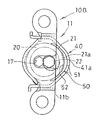
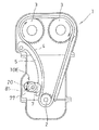
- FIGS. 21 and 22 show a tensioner 10E according to a sixth embodiment used as a load applying device of the present invention.
- the tensioner 10 ⁇ / b> E is fixed in the engine body 1, and is configured by fixing the mainspring spring 20 to the engine body 1 using the engine body 1 as a fixing member. That is, as shown in FIGS. 21 and 22, an arc-shaped receiving block 78 as a receiving portion for receiving the mainspring 20 is erected integrally from the engine block 77 of the engine body 1, and the mainspring 20 is moved to the receiving block 78.
- the mainspring spring 20 is fixed to the engine main body 1 by bringing the outer peripheral portion 21 into contact with the mainspring spring 20 and screwing the presser cover 79 onto the mainspring spring 20.
- the mainspring spring 20 is operated by being sandwiched between the receiving block 78 (engine body 1) and the recessed receiving portion 7 of the chain guide 5.
- the inner periphery of the spring 20 is hollow, and the hydraulic pressure of the engine body 1 can be supplied to the inner periphery.
- an oil passage 81 communicating with the hydraulic pump of the engine is formed in the engine block 77, and the oil passage 81 is opened at the inner peripheral portion of the mainspring spring 20.
- hydraulic pressure is supplied to the inside of the spring 20.
- the timing chain 4 can be pressed in a state where the hydraulic pressure is applied to the spring force of the mainspring spring 20. That is, when the vibration received from the timing chain 4 (chain guide 5) becomes excessive due to the change in the engine speed, the timing chain 4 may be weakly pressed by the spring force of the mainspring spring 20 alone.
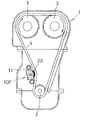
- FIG. 23 shows a tensioner 10F of a seventh embodiment used as a load applying device of the present invention.
- the tensioner 10F is disposed inside the engine body 1, the engine body 1 is not provided with the tune guide 5 as an indirect member.
- the outer peripheral part 21 of the mainspring spring 20 attached to the case 11 is directly in contact with the timing chain 4 as a movable body, and the imming chain 4 is directly pressed by this contact.
- the tension of the timing chain 4 can be adjusted also by such direct contact.
- the tensioner 10G has a structure including a plate-like elastic member 80 in addition to the propelling member 40.
- the propulsion member 40 is an indirect member formed in the same shape as the propulsion member 40 of the second embodiment, and is provided so as to cover the outer peripheral portion 21 of the mainspring spring 20 and receives a load from the chain guide 5.
- the propulsion member 40 includes an arc-shaped cover portion 41 that covers the outer peripheral portion 21 of the mainspring 20, a guide portion 42 that extends linearly from both ends of the cover portion 41 and extends away from the chain guide 5, and a guide portion 42. It is formed by the stopper part 43 formed in the terminal end of.
- the cover portion 41 has an arc portion 41a and two oblique straight portions 41b continuous from both sides of the arc portion 41a.
- the case 11 as a fixing member that accommodates the spring 20 is the same as the case 11 of the second embodiment, and is formed by assembling the first case portion 11a and the second case portion 11b.
- the first case portion 11 a is formed with a spring receiving portion 71 that rises from the flange portion 70.
- the spring receiving portion 71 is formed by an arc portion 71a and two oblique straight portions 71b continuous on both sides of the arc portion 71a.
- Two plate-like elastic members 80 are assembled to the tensioner 10 ⁇ / b> G by being disposed between the mainspring 20 and the propelling member 40 and between the mainspring 20 and the spring receiving portion 71 of the case 11. .
- a plate spring is used as the plate-like elastic member 80.
- Each plate-like elastic member 80 is disposed between the mainspring spring 20 and the propelling member 40 and between the mainspring spring 20 and the spring receiving portion 71.
- the plate-like elastic member 80 on the propelling member 40 side has a space 87 in which the intermediate portion 85 in the length direction perpendicular to the plate width direction of the mainspring spring 20 and the arc portion 41a of the covering portion 41 in the propelling member 40 can be flexibly deformed. And facing the arc portion 41a.
- the plate-like elastic member 80 on the spring receiving portion 71 side has a space 87 in which an intermediate portion 85 in the length direction orthogonal to the plate width direction of the spring spring 20 can be flexibly deformed with the arc portion 71 a of the spring receiving portion 71. And facing the arc portion 71a.
- both end portions 86 in the length direction of the plate-like elastic member 80 on the propulsion member 40 side are oblique to the propulsion member 40. While the plate-like elastic member 80 on the spring receiving portion 71 side comes into contact with the straight portion 41b, both end portions 86 in the length direction come into contact with the oblique straight portion 71b of the spring receiving portion 71, and the load from the chain guide 5 (hereinafter, referred to as “long”). In this embodiment, it is referred to as an axial load).
- 25 (a) to 25 (d) show changes in the contact position of the plate-like elastic member 80 as the diameter of the mainspring spring 20 expands or contracts.
- black triangle marks are contact portions 27 a where the outer peripheral portion 21 of the spring 20 is in contact with the plate-like elastic member 80
- white triangle marks are both end portions 82 of the plate-like elastic member 80 and the propelling member 40. This is a contact portion 27 b that comes into contact with the spring receiving portion 71.
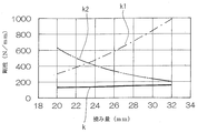
- FIG. 25A shows a state in which the mainspring spring 20 is most contracted in diameter, and the contact portion 27a of the outer peripheral portion 21 of the mainspring spring 20 is in contact with the intermediate portion 85 of each of the two plate-like elastic members 80. Further, the contact portion 27 b with the propulsion member 40 and the spring receiving portion 71 are both end portions 86 of the plate-like elastic member 80. In this state, since the distance between the contact portion 27a and the contact portion 27b is long, the bending of the plate-like elastic member 80 is large, and the rigidity (k2) of the plate-like elastic member 80 is low. On the other hand, in the mainspring 20, since the number of turns is large and the outer diameter is small, the rigidity (k1) of the mainspring 20 itself is high.
- 25 (b) to 25 (d) show a state in which the diameter of the mainspring spring 20 progresses, and the contact portion 27a with the outer peripheral portion 21 of the mainspring spring 20 is a plate-like elastic member as the mainspring spring 20 expands. Since it moves along the length direction of 80, the distance of the contact part 27a and the contact part 27b becomes small gradually.
- the contact portion 27a with the mainspring spring 20 moves to the both ends 86 side of the plate-like elastic member 80, so the distance between the contact portion 27a and the contact portion 27b is reduced, and the plate-like elastic member.
- the rigidity (k2) of 80 increases.
- the rigidity (k1) of the mainspring 20 itself is reduced.
- the rigidity of the tensioner 10G as a whole which combines the rigidity of the spring 20 and the rigidity of the plate-like elastic member 80, is changed as the diameter of the spring 20 is increased or decreased.
- FIG. 26 is a graph plotting the relationship between the allowance G (see FIG. 24) of the propelling member 40 and the rigidity (the static load and the displacement of the tip of the propelling member 40) based on the above operation.
- the propulsion member 40 and the spring receiving portion 71 will be described as rigid bodies.
- the horizontal axis in FIG. 26 is the distance between the center of the tensioner mounting hole 70g formed in the flange portion 70 of the case 11 and the tip end portion of the propelling member 40, and is the distance G shown in FIG.
- the relationship between the rigidity (k) of the entire tensioner 10G, the rigidity (k2) of the plate-like elastic member 80, and the rigidity (k1) of the mainspring spring 20 includes two plate-like elastic members 80.
- the change in rigidity (k) of the entire tensioner 10G is small, and the change in rigidity can be mitigated.
- the elastic member 80 shown in FIG. 25 slides the contact portion 27b of the propelling member 40 and the spring receiving portion 71 with friction due to vibration from the engine (load from the timing chain (movable body) 4) in the B direction / B direction. And bends in the opposite direction.
- a third hiss characteristic is generated as a difference in force between the B direction and the B direction (his characteristic).
- the tensioner becomes more flexible and stable due to the relaxation of the rigidity change and the third hiss characteristic.
- the shape, size, and material thereof are changed, the plate thickness and rigidity of the two plate-like elastic members 80 are combined to be different, or the plate-like elasticity is changed.
- the number of members 80 may be one, or the design may be arbitrarily changed according to required characteristics.
- FIG. 27 shows a tensioner 10H of a ninth embodiment used as a load applying device of the present invention.
- the tensioner 10H has the same structure as the tensioner 10C of the fourth embodiment shown in FIG. 18, and is arranged side by side along the direction of the load input from the chain guide 5 (timing chain 4 as a movable body) (left-right direction). ) And two springs 20 are arranged, and an intermediate member 60 is provided between the two springs 20.
- a propulsion member 40 is disposed on the right spring spring 20 located on the chain guide 5 side.
- the intermediate member 60 has left and right facing surfaces 61 and 62 facing the two mainspring springs 20 in an arc shape, and contacts the outer peripheral portion 21 of the left and right mainspring springs 20 in a wide area. Further, the cover portion 41 of the propulsion member 40 is formed in an arc shape, contacts the right mainspring 20 with a large area, and a spring receiving portion 71 corresponding to the left mainspring 20 is formed in an arc shape. This makes contact with the left mainspring 20 over a wide area.
- the left and right spring springs 20 are formed by winding one thin plate material 29 in a spiral shape, and the thin plate material 29 is continuous between the two springs 20. Yes. In this case, the winding direction of the thin plate material 29 is reversed in the right spring 20 and the left spring 20, and the winding portion 22 is reversed in the left and right springs 20.
- One thin plate material 29 passes between the intermediate member 60 and the guide portion 42 of the propelling member 40, thereby connecting the left and right spring springs 20.
- the two springs 20 are formed by winding one thin plate material 29 in this way, the number of the thin plate materials 29 can be reduced. Further, as with the tensioner 10C of the fourth embodiment, since the propulsion member 40 operates with the advance amount that combines the diameter expansion operations of the two left and right springs 20, the operation amount of the propulsion member 40 can be increased.
- FIG. 28 shows a modified tensioner 10I of the ninth embodiment.
- This tensioner 10I is formed by winding one thin plate material 29 in a reverse spiral shape, similarly to the tensioner 10H of FIG. 27, and thereby, the left and right spring springs 20 are formed by one thin plate material 29. Is done.
- the slit 65 is formed in the constricted portion of the intermediate portion in the vertical direction of the intermediate member 60, and the left and right springs 20 are connected by allowing the thin plate material 29 to pass through the slit 65. It can operate in the same way as the 27 tensioner 10H.
- FIG. 29 shows a tensioner 10J of a tenth embodiment used as a load applying device of the present invention.
- two springs 20 are arranged side by side (in the left-right direction) along the direction of the load input from the chain guide 5 (timing chain 4 as a movable body), and an intermediate between the two springs 20 is provided.
- a member 60 is provided.
- a propulsion member 40 as an indirect member is disposed on the right spring spring 20 side located on the chain guide 5 side.
- the propelling member 40 has a cover part 41 and two upper and lower guide parts 42 extending linearly in a direction away from the chain guide 5 from the cover part 41.
- the guide part 42 slides on the rising part 74 formed in the case 11 (lower case part 11b).
- the two left and right mainsprings 20 are formed by winding a single thin plate material 29 in a spiral shape in the opposite direction, and the thin plate material 29 is in a continuous state between the two mainspring springs 20. .
- the intermediate member 60 between the two springs 20 is divided into two in the vertical direction intersecting (orthogonal to) the load direction from the chain guide 5, whereby the intermediate member 60 is divided into the divided body 60 a and the divided body 60 b. Formed by.
- the thin plate material 29 connects the two springs 20 by passing between the divided bodies 60a and 60b.
- FIG. 30 shows a tensioner 10K of an eleventh embodiment used as a load applying device of the present invention.
- a single spring 20 is disposed in a case 11 as a fixing member.
- the case 11 is provided with a propulsion member 40 as an indirect member so as to be able to advance and retract in the direction of the chain guide 5.
- the propulsion member 40 includes a cover portion 41 that covers the outer peripheral surface 21 of the mainspring 20 and two upper and lower guide portions 42 that extend linearly in a direction away from the chain guide 5 from the cover portion 41.
- a receiving block 89 is provided inside the case 11 on the rear side in the forward / backward direction of the propelling member 40.
- the receiving block 89 is formed by two vertically divided parts 89a and 89b that intersect (orthogonal to) the direction of the load input from the chain guide 5 (timing chain 4 as a movable body).
- Each of the divided bodies 89a and 89b is formed in a triangular shape when viewed from the side, and has an inclined receiving surface 98 that receives the outer peripheral surface 21 of the spring 20.
- the two divided bodies 89a and 89b are provided in the case 11 so as to correspond to the guide portion 42 of the propelling member 40, and with the guide portion 42 as the diameter of the mainspring spring 20 increases and decreases. It can be moved back and forth in the contact direction (arrow 101 direction). The outer end locking portion 23 of the mainspring spring 20 is locked to the lower divided body 89a.
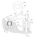
- (Twelfth embodiment) 32 and 33 show a twelfth embodiment in which the load applying device of the present invention is applied to a lash adjuster 120 of an automobile engine.
- the cylinder head 131 of the engine is provided with a valve stem 132 of an intake valve (not shown) for opening and closing the cylinder.
- the valve stem 132 moves up and down the through hole 133 of the cylinder head 131.
- a spring retainer 134 is attached to the upper end portion of the valve stem 132, and a valve spring 135 that urges the intake valve (valve stem 132) in the valve closing direction is disposed between the spring retainer 134 and the cylinder head 131.
- the lash adjuster 120 is provided on the upper surface of the cylinder head 131 so as to be close to the valve stem 132 in order to adjust the gap between the upper end surface of the valve stem 132 and the rocker arm 137.
- an adjuster attachment hole 131 a is formed on the upper surface of the cylinder head 131.
- the rocker arm 137 is a movable body of this embodiment, and opens and closes the intake valve via the valve stem 132.
- the rocker arm 137 is provided above the cylinder head 131 so as to be capable of swinging in a state of being spanned between the upper end surface of the valve stem 132 and the upper end portion of the lash adjuster 120.
- a cam 139 attached to the camshaft 138 is in contact with the upper surface of the rocker arm 137. When the cam 139 rotates, the rocker arm 137 swings up and down to open and close the intake valve.
- the rocker arm 137 is provided with hook-shaped contact portions 137b and push rods 137c at both left and right ends of the arm main body 137a with which the cam 139 contacts.
- the contact portions 137b contact the lash adjuster 120, and the push rod 137c. Is in contact with the valve stem 132.
- the lash adjuster 120 includes a mainspring 20 in which a thin plate is wound in a spiral shape, a case 11 to which the mainspring 20 is attached, and a propelling member 40 that covers the mainspring 20 on the opposite side of the case 11. And.
- the case 11 constitutes a fixing member, and is fixed in an adjuster mounting hole 131a formed in the cylinder head 131.
- a spring receiving portion 71 that receives the outer peripheral portion of the mainspring spring 20 is formed on the surface of the case 11 that faces the mainspring spring 20.
- the propulsion member 40 constitutes an indirect member, and includes a cover portion 41 that covers the mainspring 20 and two leg portions 49 that extend from the cover portion 41 to the opposite side of the rocker arm 137.
- the cover portion 41 is in contact with the outer peripheral portion of the spring 20 and, like the cover portion 41 of the second embodiment, the arc portion 41a formed in an arc shape and two continuous portions on both sides of the arc portion 41a.
- the outer periphery of the mainspring spring 20 is received by the circular arc portion 41a and the two diagonal straight portions 41b. As a result, the propelling member 40 moves forward and backward by expanding and contracting the diameter of the mainspring spring 20.
- the arc portion 41 a of the cover portion 41 abuts on the abutting portion 137 b while being fitted to the hook-like abutting portion 137 b of the rocker arm 137, and receives a load due to the swinging motion of the rocker arm 137.
- the two leg portions 49 extend from the arc portion 41a at a position orthogonal to the arrangement position of the two oblique straight portions 41b, and the end portions thereof are bent inward to form the stopper portions 43. Propulsion of the propulsion member 40 stops when the stopper portion 43 abuts the case 11.
- the swinging motion of the rocker arm 137 can be controlled by the spring force of the mainspring spring 20, thereby adjusting the gap between the upper end surface of the valve stem 132 and the rocker arm 137. it can. For this reason, the lash adjuster by the conventional hydraulic plunger can be made unnecessary.
- the propelling member 40 may be omitted and the mainspring 20 may be brought into contact with the rocker arm 137, and a plurality of mainsprings may be arranged along the direction of the load from the rocker arm 137 as in the fourth embodiment.
- the springs 20 may be arranged side by side.
- FIG. 34 and 35 show a load applying device 140 according to a thirteenth embodiment of the present invention.
- the load applying device 140 is arranged inside the engine body 1 and is fixed in the engine block 8 as a fixing member.
- the engine body 1 has a timing chain 4 as a movable body spanned between a crank sprocket 2 and cam sprockets 3, 3.
- the timing chain 4 moves while sliding on a chain guide 5 that can swing on a support shaft 6.
- the load applying device 140 is disposed between the engine block 8 as a fixed member and the timing chain 4 as a movable body.
- the load applying device 140 includes a case 141 fixed to the engine block 8, a length-direction adjusting mechanism 142 assembled to the case 141, and a spring spring 20 disposed in the case 141.
- the longitudinal adjustment mechanism 142 includes a cylindrical support shaft 143 inserted into the case 141, a propulsion shaft 144 inserted axially into the support shaft 143 so as to advance and retreat from the case 141, and the propulsion shaft 144. And a coil spring 145 for biasing.
- the propulsion shaft 144 is in contact with the timing chain 4 (chain guide 5) at the tip, and moves forward and backward in response to a change in the length direction of the timing chain 4 to apply tension to the timing chain 4.
- the adjustment mechanism 142 in the length direction has a ratchet 147 provided in the case 141.
- the ratchet 147 is disposed on the rear end side (left end side) of the support shaft 143 and is in contact with the tapered surface 144a of the rear end portion (left end portion) of the propulsion shaft 144.
- a holding frame 148 is inserted into the support shaft 143, and the ratchet spring 149 is disposed between the holding frame 148 and the ratchet 147, so that the ratchet 147 is biased in the contact direction with the propulsion shaft 144. ing.
- the mainspring 20 is sandwiched between the receiving member 151 and the propelling member 153, and the outer peripheral portion thereof is in contact with the receiving member 151 and the propelling member 153.
- the receiving member 151 is arranged on the rear end side inside the case 141, and the propelling member 153 is arranged in contact with the rear end portion of the support shaft 143.
- the load applying device 140 having such a structure, when the change in the length direction due to the extension of the timing chain 4 is large, the extension is dealt with by the adjustment mechanism 142 in the length direction having the ratchet 147.
- the spring 20 receives a buffering effect against the load from the timing chain 4. As a result, it is possible to achieve both a follow-up to the permanent elongation of the timing chain 4 and a buffering effect.
Abstract
Description
図1~図7は本発明の荷重付加装置のひとつとして用いるテンショナー10の第1実施形態を示す。 (First embodiment)
1 to 7 show a first embodiment of a
図10~図15は本発明の荷重付加装置として用いる第2実施形態のテンショナー10Aを示す。テンショナー10Aは第1実施形態1のテンショナー1のケース11及びゼンマイばね20に加えて推進部材40を組み込むものである。図10及び図11に示すように、推進部材40はゼンマイばね20の外周部21における露出部分21aを周方向で覆っており、ゼンマイばね20の拡径及び縮径に伴ってケース11に対して進退移動する。この実施形態において、推進部材40はゼンマイばね20の外周部21を覆うことにより、同ばね20の外周部21とチェーンガイド5との間に設けられる。これにより、推進部材40はゼンマイばね20の外周部21がタイミングチェーン(可動体)4に間接的に当接する間接部材を構成する。 (Second Embodiment)
10 to 15 show a
図16及び図17は本発明の荷重付加装置として用いる第3実施形態のテンショナー10Bを示す。この実施形態のテンショナー10Bは第2実施形態のテンショナー10Aの構造に対し緩衝部材50を組み込むものである。 (Third embodiment)
16 and 17 show a third embodiment of a
図18は本発明の荷重付加装置として用いる第4実施形態のテンショナー10Cを示す。テンショナー10Cは左右2つのゼンマイばね20を横並び状に配置すると共に、2つのゼンマイばね20の間に中間部材60が配置されている。2つのゼンマイばね20はタイミングチェーン4(可動体)が摺動するチェーンガイド5から入力される荷重の方向に沿って横並び状に配置されている。 (Fourth embodiment)
FIG. 18 shows a tensioner 10C according to a fourth embodiment used as a load applying device of the present invention. In the
図19は本発明の荷重付加装置として用いる第5実施形態のテンショナー10Dを示す。テンショナー10Dにおいては、ゼンマイばね20の外周部21の露出部分21aに対向して外周部21と当接するチェーンガイド5の受け部7が凹み形成されている。また、この実施形態において、エンジン本体1から伸びるばね受け部71が形成されており、このばね受け部71にゼンマイばね20の外周部21が接触している。ゼンマイばね20はこのばね受け部71とチェーンガイド5の受け部7とに挟まれるように配置され、カバー83によって覆うことによりエンジン本体1に固定される。エンジン本体1のばね受け部71はゼンマイばね20を固定する固定部材として機能する。 (Fifth embodiment)
FIG. 19 shows a
図20~図22は本発明の荷重付加装置として用いる第6実施形態のテンショナー10Eを示す。テンショナー10Eは図20に示すように、エンジン本体1内に固定されるものであり、エンジン本体1を固定部材とし、このエンジン本体1にゼンマイばね20が固定されることにより構成されている。すなわち、図21及び図22に示すように、ゼンマイばね20を受ける受け部としての円弧状の受けブロック78をエンジン本体1のエンジンブロック77から一体に起立させ、この受けブロック78にゼンマイばね20の外周部21を当接させ、押えカバー79をゼンマイばね20に被せてねじ止めすることによりゼンマイばね20がエンジン本体1に固定される。これによりゼンマイばね20は受けブロック78(エンジン本体1)とチェーンガイド5の凹み状の受け部7とに挟まれて作動する。 (Sixth embodiment)
20 to 22 show a
図23は本発明の荷重付加装置として用いる第7実施形態のテンショナー10Fを示す。テンショナー10Fはエンジン本体1の内部に配置されるが、エンジン本体1には間接部材としてのチューンガイド5が設けられていない。そして、ケース11に取り付けられたゼンマイばね20の外周部21が可動体としてのタイミングチェーン4に直接に当接しており、この当接によってイミングチェーン4を直接に押圧している。このような直接な当接によってもタイミングチェーン4の張力を調整することができる。 (Seventh embodiment)
FIG. 23 shows a
図24~図26は本発明の荷重付加装置として用いる第8実施形態のテンショナー10Gを示す。テンショナー10Gは推進部材40に加えて板状の弾性部材80を備えた構造となっている。 (Eighth embodiment)
24 to 26 show a
図27は本発明の荷重付加装置として用いる第9実施形態のテンショナー10Hを示す。テンショナー10Hは図18で示す第4実施形態のテンショナー10Cと同様な構造となっており、チェーンガイド5(可動体としてのタイミングチェーン4)から入力される荷重の方向に沿って横並び状(左右方向)に2つのゼンマイばね20が配置され、2つのゼンマイばね20の間に中間部材60が設けられている。また、チェーンガイド5側に位置する右側のゼンマイばね20には、推進部材40が配置されている。中間部材60は2つのゼンマイばね20に対向する左右の対向面61、62が円弧状となっており、左右のゼンマイばね20の外周部21と広い面積で接触する。また、推進部材40の覆い部41が円弧状に形成されており、右側のゼンマイばね20と広い面積で接触すると共に、左側のゼンマイばね20に対応したばね受け部71が円弧状に形成されることにより左側のゼンマイばね20と広い面積で接触する。 (Ninth embodiment)
FIG. 27 shows a
図29は本発明の荷重付加装置として用いる第10実施形態のテンショナー10Jを示す。テンショナー10Jはチェーンガイド5(可動体としてのタイミングチェーン4)から入力される荷重の方向に沿って横並び状(左右方向)に2つのゼンマイばね20が配置され、2つのゼンマイばね20の間に中間部材60が設けられている。チェーンガイド5側に位置する右側のゼンマイばね20側には、間接部材としての推進部材40が配置されている。推進部材40は覆い部41と、覆い部41からチェーンガイド5から離れる方向に直線状に伸びた上下2つのガイド部42とを有している。ガイド部42はケース11(下ケース部11b)に形成されている立ち上がり部74を摺動する。左右の2つのゼンマイばね20は1枚の薄板材29を逆方向に渦巻き状に巻くことによって形成されるものであり、2つのゼンマイばね20間においては薄板材29が連続した状態となっている。 (10th Embodiment)
FIG. 29 shows a
図30は本発明の荷重付加装置として用いる第11実施形態のテンショナー10Kを示す。テンショナー10Kは固定部材としてのケース11内に1つのゼンマイばね20が配置されている。また、ケース11には、間接部材としての推進部材40がチェーンガイド5の方向に進退可能に設けられている。推進部材40はゼンマイばね20の外周面21を覆う覆い部41と、覆い部41からチェーンガイド5から離れる方向に直線状に伸びた上下2つのガイド部42とを有している。 (Eleventh embodiment)
FIG. 30 shows a
図32及び図33は本発明の荷重付加装置を自動車エンジンのラッシュアジャスター120に適用した第12実施形態を示す。 (Twelfth embodiment)
32 and 33 show a twelfth embodiment in which the load applying device of the present invention is applied to a lash
図34及び図35は、本発明の第13実施形態の荷重付加装置140を示す。荷重付加装置140は図34に示すように、エンジン本体1の内部に配置されるものであり、固定部材としてのエンジンブロック8内に固定される。エンジン本体1は図1に示すように、クランクスプロケット2とカムスプロケット3、3との間に可動体としてのタイミングチェーン4が無端状となって掛け渡されている。タイミングチェーン4は支軸6に揺動可能となっているチェーンガイド5を摺動しながら移動する。荷重付加装置140は固定部材としてのエンジンブロック8と可動体としてのタイミングチェーン4との間に配置される。 (13th Embodiment)
34 and 35 show a
In the
4 タイミングチェーン(可動体)
5 チェーンガイド(ガイド部材(間接部材))
7 受け部
11 ケース
17 仮止め穴
18 ばね受け部(受け部)
20 ゼンマイばね
21 外周部
22 巻き上げ部
29 薄板材
30 巻き上げ部材
40 推進部材(間接部材)
41 覆い部
41a 円弧部
41b 斜め直線部
50 緩衝部材
53 凹凸部
60 中間部材
60a、60b 分割体
71 ばね受け部(受け部)
71a 円弧部
71b 斜め直線部
80 板状の弾性部材
85 中間部
86 両端部
87 空間
89 受けブロック
89a、89b 分割体
120 ラッシュアジャスター(荷重付加装置)
140 荷重付加装置
142 長さ方向の調整機構 10, 10A, 10B, 10C, 10D, 10E, 10F, 10G, 10H, 10I, 10J, 10K Tensioner (load application device)
4 Timing chain (movable body)
5 Chain guide (guide member (indirect member))
7 Receiving
20
41
140
Claims (17)
- 薄板材が複数回巻かれたゼンマイばねが、可動体と固定部材との間に配置され、
前記ゼンマイばねの外周部で前記可動体及び固定部材からの荷重を受けるように前記ゼンマイばねの外周部が前記可動体と直接にまたは間接部材を介して間接的に当接していることを特徴とする荷重付加装置。 A spring spring in which a thin plate material is wound a plurality of times is disposed between the movable body and the fixed member,
The outer peripheral portion of the mainspring spring is in direct contact with the movable body directly or indirectly via an indirect member so that the outer peripheral portion of the mainspring spring receives a load from the movable body and the fixed member. Load applying device. - 請求項1記載の荷重付加装置であって、
前記ゼンマイばねの拡径により前記ゼンマイばねの外周部が前記固定部材及び間接部材のそれぞれに対して少なくとも2箇所で当接することを特徴とする荷重付加装置。 The load applying device according to claim 1,
The load applying device according to claim 1, wherein an outer peripheral portion of the mainspring spring comes into contact with each of the fixing member and the indirect member at least at two locations by expanding the diameter of the mainspring spring. - 請求項1または2記載の荷重付加装置であって、
前記固定部材及び間接部材における前記ゼンマイばねの外周部との対向部分に三角状、円弧状または直線状の受け部が形成されていることを特徴とする荷重付加装置。 The load applying device according to claim 1 or 2,
A load applying device, wherein a receiving portion having a triangular shape, an arc shape, or a linear shape is formed at a portion of the fixing member and the indirect member facing the outer peripheral portion of the mainspring. - 請求項1乃至3のいずれか1項記載の荷重付加装置であって、
前記ゼンマイばねの外周部と前記間接部材または前記固定部材の少なくとも一方との間に緩衝部材が配置されていることを特徴とする荷重付加装置。 The load applying device according to any one of claims 1 to 3,
A load applying device, wherein a buffer member is disposed between an outer peripheral portion of the mainspring spring and at least one of the indirect member or the fixing member. - 請求項1乃至3のいずれか1項記載の荷重付加装置であって、
前記ゼンマイばねの外周部と前記間接部材または前記固定部材の少なくとも一方との間に、撓み変形して前記間接部材または前記固定部材と接触する板状の弾性部材が配置されていることを特徴とする荷重付加装置。 The load applying device according to any one of claims 1 to 3,
A plate-like elastic member is disposed between the outer periphery of the mainspring and at least one of the indirect member or the fixing member so as to bend and deform and contact the indirect member or the fixing member. Load applying device. - 請求項1乃至3のいずれか1項記載の荷重付加装置であって、
前記固定部材と前記間接部材との間に前記ゼンマイばねが前記可動体からの荷重の方向に沿って横並び状に複数設けられ、隣接するゼンマイばねの間に中間部材が配置されていることを特徴とする荷重付加装置。 The load applying device according to any one of claims 1 to 3,
A plurality of springs are provided between the fixed member and the indirect member in a side-by-side manner along the direction of the load from the movable body, and an intermediate member is disposed between adjacent springs. Load applying device. - 請求項5記載の荷重付加装置であって、
前記板状の弾性部材は長さ方向の両端部が前記固定部材または間接部材と接触し、長さ方向の中間部が前記固定部材または間接部材と撓み変形可能な空間を有して対向していることを特徴とする荷重付加装置。 The load applying device according to claim 5, wherein
In the plate-like elastic member, both end portions in the length direction are in contact with the fixing member or the indirect member, and an intermediate portion in the length direction is opposed to the fixing member or the indirect member with a space capable of bending deformation. A load applying device characterized by comprising: - 請求項6記載の荷重付加装置であって、
前記横並び状の複数のゼンマイばねは、ゼンマイばね間における薄板材が連続していることを特徴とする荷重付加装置。 The load applying device according to claim 6,
The load applying device, wherein the plurality of springs arranged side by side are continuous with thin plate materials between the springs. - 請求項1乃至3または請求項6のいずれか1項記載の荷重付加装置であって、
前記固定部材または中間部材は前記可動体からの荷重の方向と交差する方向に分割された複数の分割体からなり、前記分割体は前記ゼンマイばねの経の拡縮に伴って前記間接部材との接触方向に進退移動可能となっていることを特徴とする荷重付加装置。 The load applying device according to any one of claims 1 to 3 or claim 6,
The fixed member or the intermediate member includes a plurality of divided bodies that are divided in a direction intersecting the direction of the load from the movable body, and the divided body contacts the indirect member as the spring springs expand and contract. A load applying device characterized by being capable of moving back and forth in a direction. - 請求項4記載の荷重付加装置であって、
前記緩衝部材における前記ゼンマイばねの外周部との対向部分に凹凸部が形成されていることを特徴とする荷重付加装置。 The load applying device according to claim 4,
An uneven portion is formed in a portion of the buffer member facing the outer peripheral portion of the mainspring spring. - 請求項1乃至9のいずれか1項記載の荷重付加装置であって、
前記間接部材は前記ゼンマイばねの外周部を周方向で覆った状態で前記可動体の方向に進退移動可能となっている推進部材であることを特徴とする荷重付加装置。 The load applying device according to any one of claims 1 to 9,
The load applying device according to claim 1, wherein the indirect member is a propulsion member that is capable of moving back and forth in the direction of the movable body in a state in which the outer peripheral portion of the mainspring spring is covered in the circumferential direction. - 請求項1乃至11のいずれか1項記載の荷重付加装置であって、
前記固定部材と前記可動体との間に長さ方向の調整機構を介したことを特徴とする荷重付加装置。 The load applying device according to any one of claims 1 to 11,
A load applying device, wherein an adjustment mechanism in a length direction is interposed between the fixed member and the movable body. - 請求項1乃至9のいずれか1項記載の荷重付加装置であって、
前記間接部材は揺動自在な状態で前記可動体と当接するガイド部材であることを特徴とする荷重付加装置。 The load applying device according to any one of claims 1 to 9,
The load applying device, wherein the indirect member is a guide member that comes into contact with the movable body in a swingable state. - 請求項1乃至13のいずれか1項記載の荷重付加装置であって、
前記ゼンマイばねの内周部の内部に油圧が供給可能となっていることを特徴とする荷重付加装置。 The load applying device according to any one of claims 1 to 13,
A load applying device, wherein hydraulic pressure can be supplied to the inside of the inner peripheral portion of the mainspring spring. - 請求項1乃至14のいずれか1項記載の荷重付加装置であって、
前記ゼンマイばねを巻き上げ状態に保持するための仮止め手段が設けられていることを特徴とする荷重付加装置。 The load applying device according to any one of claims 1 to 14,
A load applying device, characterized in that a temporary fixing means for holding the mainspring spring in a wound state is provided. - 請求項1乃至15のいずれか1項記載の荷重付加装置であって、
前記可動体は、自動車のエンジン内で無端状となって移動するタイミングチェーンまたはタイミングベルトであることを特徴とする荷重付加装置。 The load applying device according to any one of claims 1 to 15,
The load applying device, wherein the movable body is a timing chain or a timing belt that moves endlessly in an automobile engine. - 請求項1乃至15のいずれか1項記載の荷重付加装置であって、
前記可動体は、自動車のエンジンの吸気バルブを開閉するためにスイング動作するロッカーアームであることを特徴とする荷重付加装置。 The load applying device according to any one of claims 1 to 15,
The load applying device, wherein the movable body is a rocker arm that swings to open and close an intake valve of an automobile engine.
Priority Applications (3)
| Application Number | Priority Date | Filing Date | Title |
|---|---|---|---|
| JP2014560809A JP6243361B2 (en) | 2013-02-07 | 2014-02-06 | Load applying device |
| US14/772,681 US9869378B2 (en) | 2013-02-07 | 2014-02-06 | Load application device |
| CN201480007998.6A CN104981628B (en) | 2013-02-07 | 2014-02-06 | Load attachment device |
Applications Claiming Priority (2)
| Application Number | Priority Date | Filing Date | Title |
|---|---|---|---|
| JP2013022631 | 2013-02-07 | ||
| JP2013-022631 | 2013-02-07 |
Publications (1)
| Publication Number | Publication Date |
|---|---|
| WO2014123204A1 true WO2014123204A1 (en) | 2014-08-14 |
Family
ID=51299795
Family Applications (1)
| Application Number | Title | Priority Date | Filing Date |
|---|---|---|---|
| PCT/JP2014/052810 WO2014123204A1 (en) | 2013-02-07 | 2014-02-06 | Load application device |
Country Status (4)
| Country | Link |
|---|---|
| US (1) | US9869378B2 (en) |
| JP (1) | JP6243361B2 (en) |
| CN (1) | CN104981628B (en) |
| WO (1) | WO2014123204A1 (en) |
Cited By (4)
| Publication number | Priority date | Publication date | Assignee | Title |
|---|---|---|---|---|
| WO2016021566A1 (en) * | 2014-08-08 | 2016-02-11 | 日本発條株式会社 | Load application device |
| WO2016021567A1 (en) * | 2014-08-08 | 2016-02-11 | 日本発條株式会社 | Load application device |
| JP2016142111A (en) * | 2015-02-05 | 2016-08-08 | 株式会社グレイプ | Damping structure |
| JP2018084466A (en) * | 2016-11-22 | 2018-05-31 | セイコーエプソン株式会社 | Watch driving mechanism, mechanical watch, and operation method of spiral spring |
Families Citing this family (7)
| Publication number | Priority date | Publication date | Assignee | Title |
|---|---|---|---|---|
| EP2909507B1 (en) * | 2012-10-22 | 2019-08-14 | Litens Automotive Partnership | Tensioner with increased damping |
| JP6204489B2 (en) * | 2013-11-18 | 2017-09-27 | 川崎重工業株式会社 | Engine supercharger |
| JP6600105B2 (en) * | 2017-02-02 | 2019-10-30 | 大同工業株式会社 | Tensioner |
| US10968988B2 (en) * | 2017-06-16 | 2021-04-06 | Gates Corporation | Tensioner |
| US10989280B2 (en) * | 2017-06-16 | 2021-04-27 | Gates Corporation | Tensioner |
| CN109458435A (en) * | 2017-09-06 | 2019-03-12 | 舍弗勒技术股份两合公司 | Mechanical tensioner |
| JP6948992B2 (en) * | 2018-08-01 | 2021-10-13 | 日本発條株式会社 | Tensioner |
Citations (6)
| Publication number | Priority date | Publication date | Assignee | Title |
|---|---|---|---|---|
| DE686129C (en) * | 1936-05-27 | 1940-01-04 | John Weller | Chain tensioning device |
| JPS59136063U (en) * | 1983-03-01 | 1984-09-11 | 光洋精工株式会社 | belt tensioner |
| JPH05280606A (en) * | 1992-03-27 | 1993-10-26 | Ina Waelzlager Schaeffler Kg | Tension device for belt or chain |
| JPH0893419A (en) * | 1994-09-28 | 1996-04-09 | Nittan Valve Kk | Hydraulic rush adjuster |
| JPH09184550A (en) * | 1995-11-30 | 1997-07-15 | Borg Warner Automot Inc | Coil spring chain tensioner |
| DE102010018204A1 (en) * | 2010-04-26 | 2011-10-27 | Schaeffler Technologies Gmbh & Co. Kg | Traction drive for internal combustion engine of e.g. passenger car, has tensioner formed as spiral spring, separate damping element connected with spiral spring for damping movement of tensioning rail |
Family Cites Families (45)
| Publication number | Priority date | Publication date | Assignee | Title |
|---|---|---|---|---|
| US1701820A (en) * | 1925-12-08 | 1929-02-12 | Morse Chain Co | Tensioning device for drive chains |
| US2130571A (en) * | 1936-05-27 | 1938-09-20 | Weller John | Tensioning device for transmission chains and the like |
| FR1249477A (en) * | 1959-11-18 | 1960-12-30 | Renault | Improvements to automatic chain tensioners |
| US3358522A (en) * | 1965-08-16 | 1967-12-19 | Morse Chain Co | Cam chain tensioner |
| JPS5848788B2 (en) * | 1979-10-12 | 1983-10-31 | 日本発条株式会社 | Lock mechanism in propulsion device |
| DE3704521C2 (en) * | 1987-02-13 | 1996-09-12 | Skf Gmbh | Belt tensioner |
| DE3810188A1 (en) * | 1988-03-25 | 1989-10-05 | Skf Gmbh | RUNNING RAIL TO TENSION A TRANSMISSION |
| US4990123A (en) * | 1989-06-13 | 1991-02-05 | Gkn Automotive, Inc. | Continuously variable transmission system having a variable diameter pulley with resiliently biased belt engaging members |
| US4906222A (en) * | 1989-07-07 | 1990-03-06 | Dayco Products, Inc. | Belt tensioner and method of making the same |
| US4938734A (en) * | 1989-09-06 | 1990-07-03 | Dayco Products, Inc. | Belt tensioner and method of making the same |
| US4971589A (en) * | 1989-12-13 | 1990-11-20 | Dayco Products, Inc. | Belt tensioner and method of making the same |
| JP2805390B2 (en) * | 1990-10-12 | 1998-09-30 | キヤノン株式会社 | Image forming device |
| US5176581A (en) * | 1991-06-06 | 1993-01-05 | Kumm Industries, Inc. | Self-energized controllable belt tensioner |
| US5370586A (en) * | 1992-07-22 | 1994-12-06 | Hasco Spring Industries, Inc. | Tension regulating device for belt drives |
| US5277667A (en) * | 1992-09-18 | 1994-01-11 | Dayco Products, Inc. | Belt tensioning system and method of making |
| US5354242A (en) * | 1992-10-08 | 1994-10-11 | St John Richard C | Automatic belt tensioner with an enclosed flat wire power spring and improved zeroing and damping means |
| DE4339596A1 (en) * | 1993-11-20 | 1995-05-24 | Skf Gmbh | Temperature dependent belt tensioning mechanism |
| US5462494A (en) * | 1994-10-20 | 1995-10-31 | Dayco Products, Inc. | Belt tensioner and method of making the same |
| US5443424A (en) * | 1994-10-20 | 1995-08-22 | Dayco Products, Inc. | Belt tensioner and method of making the same |
| DE4437926C1 (en) * | 1994-10-24 | 1996-02-08 | Daimler Benz Ag | Tensioning device for chain of IC engine, esp. oil pump chain |
| US5558587A (en) * | 1995-05-15 | 1996-09-24 | Eaton Corporation | Self-contained hydraulic belt tensioner |
| JP3280339B2 (en) * | 1999-03-24 | 2002-05-13 | 株式会社椿本チエイン | Chain transmission tensioner lever |
| US6231465B1 (en) * | 1999-08-13 | 2001-05-15 | Dayco Products, Inc. | Belt tensioner assembly with unidirectional damping |
| US6689001B2 (en) * | 2001-12-12 | 2004-02-10 | Dayco Products, Llc | Adaptive belt tensioner system for control of reversible torque load pulley |
| US7163478B2 (en) * | 2001-12-12 | 2007-01-16 | Dayco Products, Llc | Belt tensioner having an automatically adjustable travel stop |
| JP2003222208A (en) * | 2002-01-31 | 2003-08-08 | Tsubakimoto Chain Co | Tensioner lever for transmission medium |
| US7118504B2 (en) * | 2002-02-07 | 2006-10-10 | Dayco Products, Llc | Hydraulic asymmetric damped belt tensioner |
| US6682452B2 (en) * | 2002-02-14 | 2004-01-27 | Dayco Products, Llc | Belt tensioner with pivot bushing |
| US7837582B2 (en) * | 2002-09-30 | 2010-11-23 | Fenner, Inc. | Bi-directional belt tensioner |
| US20110207568A1 (en) * | 2002-09-30 | 2011-08-25 | Gary Smith | Bi-Directional Belt Tensioner |
| US7883436B2 (en) * | 2004-09-15 | 2011-02-08 | Fenner U.S., Inc. | Bi-directional tensioner |
| US7354363B2 (en) * | 2004-05-18 | 2008-04-08 | Dayco Products, Llc | Magnetorheological fluid V-ribbed belt tensioner with through shaft |
| ITTO20030819A1 (en) * | 2003-10-17 | 2005-04-18 | Dayco Europe Srl | BI-ARM TENSIONER FOR A TRANSMISSION BELT OF A MOTOR VEHICLE. |
| US7261655B2 (en) * | 2004-06-24 | 2007-08-28 | Vargas Eladio A | Variable speed flat belt transmission and variable diameter pulley for use in same |
| EP1893894B1 (en) * | 2005-06-20 | 2010-12-22 | Dayco Europe S.R.L. Con Unico Socio | Asymetric damping belt tensioner |
| BRPI0520542B1 (en) * | 2005-07-29 | 2018-05-02 | Dayco Europe S.R.L. Con Unico Socio | SHOE TENSOR FOR AN OIL SYNCHRONOUS DRIVE |
| KR101322173B1 (en) * | 2006-03-22 | 2013-10-25 | 리텐스 오토모티브 파트너쉽 | Tensioner for flexible drives |
| JP4473301B2 (en) * | 2007-10-29 | 2010-06-02 | 株式会社椿本チエイン | Chain transmission tensioner lever |
| US20100261564A1 (en) * | 2009-04-13 | 2010-10-14 | Hughes Thomas E | Rotary tensioner |
| JP2011140972A (en) * | 2010-01-06 | 2011-07-21 | Ntn Corp | Tension adjusting device of wrapping transmission member in wrapping transmission device |
| US20110230286A1 (en) * | 2010-03-17 | 2011-09-22 | Eli Cohen | Variable Drive Transmission |
| EP2395259B1 (en) * | 2010-06-11 | 2012-11-07 | iwis motorsysteme GmbH & Co. KG | Tensioning device with stop bracket |
| JP5425015B2 (en) * | 2010-08-09 | 2014-02-26 | 株式会社椿本チエイン | Chain tensioner lever |
| JP2013249939A (en) * | 2012-06-04 | 2013-12-12 | Tsubakimoto Chain Co | Hydraulic tensioner |
| DE102013102562B4 (en) * | 2013-03-13 | 2021-05-27 | Muhr Und Bender Kg | Use of a spring in a belt tensioning device, belt tensioning device and assembly arrangement |
-
2014
- 2014-02-06 US US14/772,681 patent/US9869378B2/en active Active
- 2014-02-06 JP JP2014560809A patent/JP6243361B2/en active Active
- 2014-02-06 CN CN201480007998.6A patent/CN104981628B/en active Active
- 2014-02-06 WO PCT/JP2014/052810 patent/WO2014123204A1/en active Application Filing
Patent Citations (6)
| Publication number | Priority date | Publication date | Assignee | Title |
|---|---|---|---|---|
| DE686129C (en) * | 1936-05-27 | 1940-01-04 | John Weller | Chain tensioning device |
| JPS59136063U (en) * | 1983-03-01 | 1984-09-11 | 光洋精工株式会社 | belt tensioner |
| JPH05280606A (en) * | 1992-03-27 | 1993-10-26 | Ina Waelzlager Schaeffler Kg | Tension device for belt or chain |
| JPH0893419A (en) * | 1994-09-28 | 1996-04-09 | Nittan Valve Kk | Hydraulic rush adjuster |
| JPH09184550A (en) * | 1995-11-30 | 1997-07-15 | Borg Warner Automot Inc | Coil spring chain tensioner |
| DE102010018204A1 (en) * | 2010-04-26 | 2011-10-27 | Schaeffler Technologies Gmbh & Co. Kg | Traction drive for internal combustion engine of e.g. passenger car, has tensioner formed as spiral spring, separate damping element connected with spiral spring for damping movement of tensioning rail |
Cited By (4)
| Publication number | Priority date | Publication date | Assignee | Title |
|---|---|---|---|---|
| WO2016021566A1 (en) * | 2014-08-08 | 2016-02-11 | 日本発條株式会社 | Load application device |
| WO2016021567A1 (en) * | 2014-08-08 | 2016-02-11 | 日本発條株式会社 | Load application device |
| JP2016142111A (en) * | 2015-02-05 | 2016-08-08 | 株式会社グレイプ | Damping structure |
| JP2018084466A (en) * | 2016-11-22 | 2018-05-31 | セイコーエプソン株式会社 | Watch driving mechanism, mechanical watch, and operation method of spiral spring |
Also Published As
| Publication number | Publication date |
|---|---|
| US20160153529A1 (en) | 2016-06-02 |
| CN104981628A (en) | 2015-10-14 |
| CN104981628B (en) | 2018-10-26 |
| US9869378B2 (en) | 2018-01-16 |
| JPWO2014123204A1 (en) | 2017-02-02 |
| JP6243361B2 (en) | 2017-12-06 |
Similar Documents
| Publication | Publication Date | Title |
|---|---|---|
| JP6243361B2 (en) | Load applying device | |
| EP1915549B1 (en) | Long mechanical tensioner with a compliant blade spring | |
| EP1715217B1 (en) | Mechanical chain tensioner with ratcheting device | |
| JP5133265B2 (en) | Force limiting tensioning arm | |
| KR101318131B1 (en) | Chain tensioning device linking two strands of a chain drive | |
| JP2008544195A (en) | Mechanical chain tensioner with followable blade spring | |
| EP2008001A1 (en) | Ratchet mechanism for a chain drive | |
| US8608601B2 (en) | Tensioning device | |
| JP2008509358A (en) | Composite chain drive guide | |
| US20060089220A1 (en) | Chain tensioner | |
| JP2009509101A (en) | Friction damping blade tensioner | |
| US10794455B2 (en) | Tensioner | |
| JP2016038036A (en) | Load application device | |
| US9850989B2 (en) | Compliant tensioner arm | |
| CN110114592B (en) | Winding transmission body tensioning device | |
| WO2016021567A1 (en) | Load application device | |
| JP4777660B2 (en) | Blade tensioner device | |
| JP5800191B2 (en) | Tensioner |
Legal Events
| Date | Code | Title | Description |
|---|---|---|---|
| 121 | Ep: the epo has been informed by wipo that ep was designated in this application |
Ref document number: 14749395 Country of ref document: EP Kind code of ref document: A1 |
|
| DPE1 | Request for preliminary examination filed after expiration of 19th month from priority date (pct application filed from 20040101) | ||
| ENP | Entry into the national phase |
Ref document number: 2014560809 Country of ref document: JP Kind code of ref document: A |
|
| NENP | Non-entry into the national phase |
Ref country code: DE |
|
| WWE | Wipo information: entry into national phase |
Ref document number: IDP00201505352 Country of ref document: ID |
|
| WWE | Wipo information: entry into national phase |
Ref document number: 14772681 Country of ref document: US |
|
| 122 | Ep: pct application non-entry in european phase |
Ref document number: 14749395 Country of ref document: EP Kind code of ref document: A1 |