WO2014122952A1 - Beauty aid - Google Patents
Beauty aid Download PDFInfo
- Publication number
- WO2014122952A1 WO2014122952A1 PCT/JP2014/050388 JP2014050388W WO2014122952A1 WO 2014122952 A1 WO2014122952 A1 WO 2014122952A1 JP 2014050388 W JP2014050388 W JP 2014050388W WO 2014122952 A1 WO2014122952 A1 WO 2014122952A1
- Authority
- WO
- WIPO (PCT)
- Prior art keywords
- rollers
- handle
- cosmetic device
- support shafts
- skin
- Prior art date
Links
Images


Classifications
-
- A—HUMAN NECESSITIES
- A61—MEDICAL OR VETERINARY SCIENCE; HYGIENE
- A61H—PHYSICAL THERAPY APPARATUS, e.g. DEVICES FOR LOCATING OR STIMULATING REFLEX POINTS IN THE BODY; ARTIFICIAL RESPIRATION; MASSAGE; BATHING DEVICES FOR SPECIAL THERAPEUTIC OR HYGIENIC PURPOSES OR SPECIFIC PARTS OF THE BODY
- A61H15/00—Massage by means of rollers, balls, e.g. inflatable, chains, or roller chains
- A61H15/0092—Massage by means of rollers, balls, e.g. inflatable, chains, or roller chains hand-held
-
- A—HUMAN NECESSITIES
- A61—MEDICAL OR VETERINARY SCIENCE; HYGIENE
- A61H—PHYSICAL THERAPY APPARATUS, e.g. DEVICES FOR LOCATING OR STIMULATING REFLEX POINTS IN THE BODY; ARTIFICIAL RESPIRATION; MASSAGE; BATHING DEVICES FOR SPECIAL THERAPEUTIC OR HYGIENIC PURPOSES OR SPECIFIC PARTS OF THE BODY
- A61H7/00—Devices for suction-kneading massage; Devices for massaging the skin by rubbing or brushing not otherwise provided for
- A61H7/007—Kneading
-
- A—HUMAN NECESSITIES
- A61—MEDICAL OR VETERINARY SCIENCE; HYGIENE
- A61N—ELECTROTHERAPY; MAGNETOTHERAPY; RADIATION THERAPY; ULTRASOUND THERAPY
- A61N1/00—Electrotherapy; Circuits therefor
- A61N1/18—Applying electric currents by contact electrodes
- A61N1/32—Applying electric currents by contact electrodes alternating or intermittent currents
- A61N1/36—Applying electric currents by contact electrodes alternating or intermittent currents for stimulation
- A61N1/36014—External stimulators, e.g. with patch electrodes
-
- A—HUMAN NECESSITIES
- A61—MEDICAL OR VETERINARY SCIENCE; HYGIENE
- A61H—PHYSICAL THERAPY APPARATUS, e.g. DEVICES FOR LOCATING OR STIMULATING REFLEX POINTS IN THE BODY; ARTIFICIAL RESPIRATION; MASSAGE; BATHING DEVICES FOR SPECIAL THERAPEUTIC OR HYGIENIC PURPOSES OR SPECIFIC PARTS OF THE BODY
- A61H7/00—Devices for suction-kneading massage; Devices for massaging the skin by rubbing or brushing not otherwise provided for
- A61H7/007—Kneading
- A61H2007/009—Kneading having massage elements rotating on parallel output axis
-
- A—HUMAN NECESSITIES
- A61—MEDICAL OR VETERINARY SCIENCE; HYGIENE
- A61H—PHYSICAL THERAPY APPARATUS, e.g. DEVICES FOR LOCATING OR STIMULATING REFLEX POINTS IN THE BODY; ARTIFICIAL RESPIRATION; MASSAGE; BATHING DEVICES FOR SPECIAL THERAPEUTIC OR HYGIENIC PURPOSES OR SPECIFIC PARTS OF THE BODY
- A61H15/00—Massage by means of rollers, balls, e.g. inflatable, chains, or roller chains
- A61H2015/0007—Massage by means of rollers, balls, e.g. inflatable, chains, or roller chains with balls or rollers rotating about their own axis
- A61H2015/0042—Balls or spheres
-
- A—HUMAN NECESSITIES
- A61—MEDICAL OR VETERINARY SCIENCE; HYGIENE
- A61H—PHYSICAL THERAPY APPARATUS, e.g. DEVICES FOR LOCATING OR STIMULATING REFLEX POINTS IN THE BODY; ARTIFICIAL RESPIRATION; MASSAGE; BATHING DEVICES FOR SPECIAL THERAPEUTIC OR HYGIENIC PURPOSES OR SPECIFIC PARTS OF THE BODY
- A61H15/00—Massage by means of rollers, balls, e.g. inflatable, chains, or roller chains
- A61H2015/0007—Massage by means of rollers, balls, e.g. inflatable, chains, or roller chains with balls or rollers rotating about their own axis
- A61H2015/0057—Massage by means of rollers, balls, e.g. inflatable, chains, or roller chains with balls or rollers rotating about their own axis the axis being resiliently biased
-
- A—HUMAN NECESSITIES
- A61—MEDICAL OR VETERINARY SCIENCE; HYGIENE
- A61H—PHYSICAL THERAPY APPARATUS, e.g. DEVICES FOR LOCATING OR STIMULATING REFLEX POINTS IN THE BODY; ARTIFICIAL RESPIRATION; MASSAGE; BATHING DEVICES FOR SPECIAL THERAPEUTIC OR HYGIENIC PURPOSES OR SPECIFIC PARTS OF THE BODY
- A61H2201/00—Characteristics of apparatus not provided for in the preceding codes
- A61H2201/12—Driving means
- A61H2201/1253—Driving means driven by a human being, e.g. hand driven
Definitions
- the present invention relates to a cosmetic device provided with a massage roller for realizing beautiful skin.
- Patent Document 1 Conventionally, as this type of beauty device, for example, configurations as disclosed in Patent Document 1 and Patent Document 2 have been proposed.
- three stainless steel balls stainless ball
- a ball support in a state where the stainless steel balls (stainless ball) are arranged at equal intervals on the main body. And these stainless steel balls are pressed against the skin and moved to massage the skin.
- the cosmetic device described in Patent Document 2 can obtain the same massage effect as Patent Document 1 by two spherical rollers. Furthermore, the cosmetic device of Patent Document 2 can obtain a massage effect that picks up the skin between both rollers when it is moved while rotating in one direction with both rollers pressed against the skin. it can. However, since picking up the skin can be obtained only when the roller rotates in one direction, if you try to obtain a massage effect that presses the skin and a massage effect that picks up the skin at the same time, make the cosmetic device smaller Since it was necessary to reciprocate, handling was troublesome.
- the present invention has been made by paying attention to such problems existing in the prior art.
- the purpose is to provide a cosmetic device that can simultaneously obtain a massage effect that presses the skin and a massage effect that picks up the skin only by moving the body in one direction.
- the cosmetic device is supported by the main body, at least three axes that are supported by the main body and extend in a pre-tilt shape, and are rotatable on the support shafts. And a supported massage roller.
- This cosmetic device is a shaft that extends in a slanting shape when the body is moved in one direction and the other direction along a direction intersecting the arrangement direction of a pair of adjacent rollers with each roller pressed against the skin.
- Each roller rotates around a support axis on the line.
- the adjacent rollers in the adjacent state rotate about the intersecting axis line so as to spread toward the front side in the moving direction, a massage effect that presses the skin is obtained.
- the next roller in the adjacent state rotates inward about the intersecting axis so as to spread toward the rear side in the moving direction, so that the skin is picked up between the two rollers. Such a massage effect is obtained.
- this cosmetic device can simultaneously obtain different massage effects of pressing against the skin and picking up by simply moving the body in one direction without reciprocating the main body.
- the “inclined tip shape” means a state in which the gap is inclined so as to widen toward the tip side.
- the support shafts are positioned on at least three axes that extend in an inclined state so that the interval increases toward the distal end side.
- this cosmetic device exhibits an effect that it is possible to simultaneously obtain a massage effect that presses the skin and a massage effect that picks up the skin only by moving the body in one direction.
- FIG. 6 is an enlarged cross-sectional view taken along line 6-6 in FIG.
- FIG. 7 is a partially enlarged sectional view taken along line 7-7 in FIG. It is sectional drawing which shows the support structure of a roller. It is sectional drawing which shows the example of a change of the support structure of a roller.
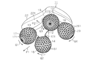
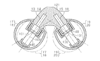
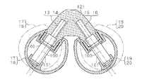
- the cosmetic device 11 of this embodiment includes a main body 12 made of synthetic resin.
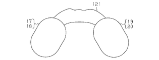
- the main body 12 is formed by projecting four leg portions 121 at four corners. These leg portions 121 are located at the vertexes of the rectangle.
- a total of four support shafts 13, 14, 15, 16 project from each leg 121.
- each of the support shafts 13 to 16 is inclined with respect to the vertical line in a state where it is installed with respect to the horizontal plane, and has a forwardly inclined shape and a rectangular corner. It is located on the corner. That is, as shown in FIGS.
- the two pairs of support shafts 13 and 14 and the support shafts 15 and 16 that are located at both ends of the short side of the rectangle and sandwich the short side are the leading edges in the side projection. It has a spreading and inclined shape, and the inter-axis distance L1 is narrow. Further, as shown in FIGS. 5A and 5B, the two pairs of support shafts 13 and 15 and the support shafts 14 and 16 that are located at both ends of the long side of the rectangle and sandwich the long side are the side projections. Is inclined forward and 90 ° in side projection, and the inter-axis distance L2 is formed wider than the distance L1. Accordingly, each of the four support shafts 13, 14, 15, and 16 has two pairs of forward and inclined shapes in the side projection from one direction, and two combinations of two in the side projection from the other direction different by 90 degrees. The pair is forward and inclined.
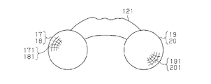
- the support shafts 13 to 16 support massage rollers 17, 18, 19, and 20 via bearings 40 at their distal ends, respectively.
- the axis 101 that is the center of rotation of each of the rollers 17 to 20 coincides with the axis 100 of the support shafts 13 to 16.
- Each of the rollers 17 to 20 is formed of a synthetic resin so as to be substantially spherical as a whole.
- Each of the rollers 17 to 20 has a large number of triangular small planes 171, 181, 191, 201 formed on the outer surface for giving a suitable stimulus to the skin surface and tissue.
- Each of the rollers 17 to 20 is provided with a conductive metal plating constituting a conductive material on its outer surface.
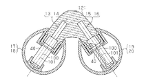
- the main body 12 has a boss 21 formed at the center.
- the handle 22 is supported on the main body 12 by inserting a support shaft 23 protruding from the center of the lower surface of the handle 22 into the boss portion 21.
- the handle 22 is rotatable in the plane of arrangement of the rollers 17 to 20 and can be moved up and down in FIG.
- the handle 22 is sized to cover the entire top surface of the main body 12, and is formed of synthetic resin so as to have a substantially flat weight shape.
- the handle 22 has an arcuate concave gripping part 221 formed on both sides.
- the handle 22 has a conductive metal plating that constitutes a conductive material on its outer surface.
- the conductive metal plating of the handle 22 and the conductive metal plating of the rollers 17 to 20 are electrically insulated.
- a spring 25 for applying an elastic force in a direction of moving the handle 22 downward in FIG. ing is provided between the spring seat 24 fixed to the lower end portion of the support shaft 23 and the lower end edge of the boss portion 21, a spring 25 for applying an elastic force in a direction of moving the handle 22 downward in FIG. ing.
- the handle 22 has a metal collar 26 fixed at the center of the bottom surface in an embedded state.
- the collar 26 has a pair of hemispherical engagement protrusions 27 formed on the lower surface at an interval of 180 degrees on the same circumference centered on the axis of the support shaft 23.
- the main body 12 has a plurality of pairs of hemispherical engaging recesses 28, 29, 30, 31 that can engage with the engaging protrusions 27 at the center of the upper surface of the boss portion 21.
- Each pair of engaging recesses 28 to 31 is formed at an interval of 45 degrees on the same circumference centered on the axis of the support shaft 23.
- the engagement protrusion 27 is engaged with each of the engagement recesses 28 to 31.
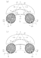
- the rotational position of the handle 22 is regulated every 45 degrees, and the orientation of the handle 22 is arbitrarily adjusted within a range of 360 degrees every 45 degrees, as shown by solid lines and chain lines in FIG.
- the adjustment angle and angle range of the handle 22 can be arbitrarily set by changing the number of engagement recesses and the arrangement pitch.
- the engagement protrusion 27 and the engagement recesses 28 to 31 constitute a holding mechanism for holding the handle 22 in a plurality of directions.
- the handle 22 has a pair of recesses 32 formed on the upper surface.
- This handle 22 has a solar cell panel 33 installed in each recess 32.
- the output of the solar cell panel 33 is supplied to the conductive metal plating of the rollers 17 to 20 and the conductive metal plating of the handle 22 through a power supply line (not shown). Therefore, each conductive metal plating constitutes an output terminal of the solar cell panel 33. Therefore, the electric power generated by the solar cell panel 33 is supplied to the conductive metal plating of the rollers 17 to 20 and the handle 22.
- an electric circuit having a human body interposed between the conductive parts is formed, and a weak current flows between the rollers 17 to 20 and the handle 22 in the body including the skin, thereby stimulating the body.
- the cosmetic effect is enhanced by the promotion.
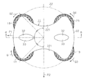
- this beauty machine 11 When this beauty machine 11 is used to massage a thin part with a high curvature and low flatness, such as a body arm, a leg, and a neck, the grip part 221 of the handle 22 is gripped, and a chain line in FIG. As shown in the figure, the rollers 17 to 20 are pressed against the skin 34 where massage is desired. Then, the rollers 17 and 18 and the rollers 19 and 20 arranged at a narrow interval are moved in either the direction of the arrow P1 in FIGS. 2 and 3 or the direction opposite to the arrow P1. .
- the inter-axis distance L1 between the support shafts 13 and 14 and the support shafts 15 and 16 that support the pair of rollers 17 and 18 and the pair of rollers 19 and 20 is small. Therefore, as described above, it is possible to effectively massage a portion having a large curvature, such as a body arm or ankle, with the two pairs of rollers 17 and 18 and rollers 19 and 20. In particular, as shown in FIG. 4B, the action of massaging so that the skin 34 is picked up is effective for beauty.
- the gripping part 221 of the handle 22 is gripped and the rollers 17 to 20 are pressed against the skin 34 such as the thigh and waist. Then, the rollers 17 and 19 and the rollers 18 and 20 are moved in the direction of the arrow P2 in FIG. 3, for example. Then, as shown in FIG. 5A, the preceding pair of rollers 17 and 19 is massaged so that the skin 34 is pressed. At the same time, as shown in FIG. 5B, massage is performed between the pair of following rollers 18 and 20 so that the skin 34 is picked up.
- the angle of the handle 22 can be arbitrarily adjusted in units of 45 degrees over a range of 360 degrees. For this reason, the handle 22 can be easily held by selecting the handle 22 at an appropriate angle according to the part to be massaged. For this reason, a massage can be easily performed with little fatigue.
- each support shaft 13 to 16 is provided on the main body 12 so as to protrude forward and in an inclined manner.
- Each support shaft 13 to 16 rotatably supports massage rollers 17 to 20.
- a massage effect that presses the skin 34 with the pair of rollers 17 to 20 in the adjacent state is obtained.
- a massage effect that picks up the skin 34 between the rollers 17 to 20 can be obtained in the pair of rollers 17 to 20 that are adjacent to each other. Therefore, different types of massage effects of pressing against the skin 34 and muscles and picking up can be obtained simultaneously by merely moving the main body 12 in one direction without reciprocating.
- the support shafts 13 to 16 are provided in two pairs of four, and two pairs of supports are supported by the distance L1 between the two pairs of support shafts 13 and 14 and the support shafts 15 and 16.
- the inter-axis distance L2 between the shafts 13 and 15 and the support shafts 14 and 16 is configured to be large. Therefore, when massaging a thin part such as an arm or an ankle, the rollers 17 and 18 and the rollers 19 and 20 supported by the two pairs of support shafts 13 and 14 and the support shafts 15 and 16 having a small inter-axis distance L1 are used.
- the main body 12 is moved in a state where is set to the front and rear in the moving direction.
- the two pairs of rollers 17 to 20 can exert different massage effects by pressing and picking up a thin portion having a large curvature such as an arm.
- the rollers 17 and 19 supported by the two pairs of support shafts 13 and 15 and the support shafts 14 and 16 having a large inter-axis distance L2 are used.
- the main body 12 is moved in the state which made the rollers 18 and 20 the front and back. This makes it possible to exert different massage effects between pressing on a thick part and picking in the two pairs of rollers 17 to 20. Therefore, the rollers 17 to 20 can be properly used according to the part to be massaged, and a good massage effect can be obtained at a desired part of the body.
- a handle 22 is provided on the main body 12. For this reason, the handle
- the cosmetic device 11 is configured so that the orientation of the handle 22 can be changed and is held at a desired angle. For this reason, for example, by changing the direction of the handle 22 according to the part of the massage, the main body 12 can be moved freely and reasonably in a desired direction, and good operability and a massage effect can be obtained. Obtainable.
- this embodiment can also be changed and embodied as follows.
- the number of support shafts 13 to 16, that is, the number of rollers is three, or five or more.
- the number of rollers is three, by making all the intervals between each roller different, it is possible to massage appropriately according to different curvatures of each part of the body, or to change the amount picked up It becomes possible to do.
- the direction of the handle 22 is configured so that it can be changed at an angle different from the above configuration, for example, every 30 degrees.
- the handle 22 has a shape different from that of the above embodiment, such as a rod shape, a ball shape, or an annular shape.
- the handle 22 should be omitted.
- the main body 12 has a handle function.
- the handle 22 is integrated with the main body 12.
- the main body 12 is formed of a material other than synthetic resin, for example, metal, wood, stone, ceramic, or the like.
- the handle 22 is made of a material other than synthetic resin, for example, metal or wood, stone or ceramic. -Omit conductive metal plating on the main body 12, the handle 22, and the rollers 17-20.
- an embedded output terminal of the solar cell panel 33 is provided on the surface of the main body 12, the handle 22, the rollers 17 to 20, and the like so that the user's skin can come into contact with the output terminal.
- the number of the solar cell panels 33 should be 1 or 3 or more. -Omit the solar panel 33. • At least one roller with a different diameter should be provided for other rollers. Therefore, a case where all the rollers have different diameters can be considered.
- the central axes 100 of the support shafts 13 to 16 and the central axis 101 of the at least one roller 17 to 20 are not aligned with each other, and they are arranged at different positions to support the support shafts 13 to 16
- the central axis 101 of the rollers 17 to 20 is inclined with respect to the central axis 100 of the roller.
- the central axis 101 of the rollers 17 to 20 may or may not intersect with the central axis 100 of the support shafts 13 to 16. In this way, as indicated by a two-dot chain line in FIG. 9, the rollers 17 to 20 swing with the rotation thereof, so that the contact pressure to the skin can be increased or decreased.
- the central axis 101 of at least one roller 17-20 is eccentric with respect to the central axis 100 of the support shafts 13-16.
- the central axis 101 of the rollers 17 to 20 is parallel to the central axis 100 of the support shafts 13 to 16.
- the rollers 17 to 20 rotate eccentrically, so that the contact pressure against the skin can be increased or decreased.
- At least one of the rollers 17 to 20 supports the support shafts 13 to 16 rotatably on the main body 12 via bearings, and the rollers 17 to 20 are fixed to the support shafts 13 to 16. Therefore, in this configuration, the support shafts 13 to 16 and the rollers 17 to 20 are rotated together. Further, in this configuration, although not illustrated, in at least one of the rollers 17 to 20, between the portion supported by the leg portion 121 of the support shafts 13 to 16 and the portion supporting the rollers 17 to 20, The support shafts 13 to 16 are bent or curved. In this way, the support shafts 13 to 16 are formed in a dogleg shape or a crank shape as a whole. Accordingly, since the rollers 17 to 20 are rotated while being swung or rotated eccentrically, the contact pressure to the skin can be increased or decreased.
- rollers 17-20 as shown in Figs. 11-14.
- the rollers 17 to 20 are formed in a spherical shape
- in FIG. 12 are formed in an elliptical sphere shape or a rugby ball shape
- in FIG. 13 are formed in a cylindrical shape with hemispherical ends
- in FIG. It is formed in a balloon shape.
- the outer peripheral surface has a cylindrical shape, that is, a drum shape or a barrel shape, or a polygonal cylindrical shape (10-sided tube, 12-sided tube, etc.) To do.
- the skin can be picked up at the tip portion with a large curvature and the picked-up state can be maintained at the portion with a small curvature, thus improving the picking effect. be able to.
- it may be a quadrangle as shown in FIG. 11, an elongated shape as shown in FIG. 12, or a circular shape as shown in FIG.
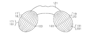
- an annular line 103 is attached to the maximum diameter portion of the rollers 17-20.
- the rollers 17 to 20 in FIG. 13 have a smooth surface and are not formed with the small planes 171, 181, 191 and 201.
- the surface of the rollers 17 to 20 may be a satin finish or a dimple having a large number of small holes. Also good.
- the rollers 17 to 20 should have a shape having a number of warped projections on the surface.
- a part or a plurality of portions of the outer periphery in the portion of the roller 17-20 having various shapes such as a spherical shape or a rugby ball shape in contact with the skin are recessed or protruded. In this way, since the distance between the rollers 17 to 20 changes as the rollers 17 to 20 rotate, the contact pressure on the skin can be increased or decreased.
- (B) A cosmetic device in which the axis of the roller is inclined with respect to the axis of the support shaft.
- C A cosmetic device in which the axis of the roller is parallel to the axis of the support shaft.
Abstract
Description
特許文献1に記載の従来構成においては、本体上に3個のステンレス球(stainless ball)が等間隔をおいた状態で、ボール支えを介して回転可能に支持されている。そして、これらのステンレス球が肌に押し当てられて移動されることにより、肌がマッサージされる。 Conventionally, as this type of beauty device, for example, configurations as disclosed in
In the conventional configuration described in
特許文献1に記載の美容器は、各ステンレス球は肌を押圧したり、肌の上を転がったりするだけであるため、有効なマッサージ効果を得ることは難しい。 However, these conventional cosmetic devices have the following problems.
In the beauty device described in
図1及び図2に示すように、この実施形態の美容器11は合成樹脂よりなる本体12を備えている。図2及び図6に示すように、本体12は4箇所の隅角部に4本の脚部121を突出させて形成している。これら脚部121は長方形の頂点部に位置している。合計4本の支持軸13,14,15,16が各脚部121から突設している。図4及び図5に示すように、各支持軸13~16は、水平面に対して設置された状態で、鉛直線に対して傾斜状に延びて、先広がり傾斜状をなすとともに、長方形のコーナー部(corner)上に位置している。すなわち、図4(a)(b)に示すように、長方形の短辺の両端に位置してその短辺を挟む二対の支持軸13,14及び支持軸15,16は、側面投影において先広がり傾斜状をなし、軸間間隔L1は狭く形成されている。また、図5(a)(b)に示すように、長方形の長辺の両端に位置してその長辺を挟む二対の支持軸13,15及び支持軸14,16は、前記側面投影とは90度異なる側面投影において先広がり傾斜状をなし、軸間間隔L2は前記間隔L1より広く形成されている。従って、4本の各支持軸13,14,15,16は、一方向からの側面投影において二対が先広がり傾斜状であるとともに、90度異なる他方向からの側面投影において他の組み合わせの二対が先広がり傾斜状である。 Hereinafter, an embodiment of a cosmetic device will be described with reference to the drawings.
As shown in FIGS. 1 and 2, the
この美容器11を使用して、身体の腕、足、首等の曲率が大きく平面度が低い細い部位をマッサージする場合、ハンドル22の把持部221を把持して、図4(a)に鎖線で示すように、各ローラ17~20をマッサージしたい箇所の肌34に押し当てる。そして、狭い間隔で配置されたローラ17,18及びローラ19,20の各配置方向と直交する方向である図2及び図3の矢印P1方向、又は矢印P1とは反対方向のいずれかに移動させる。 Next, the operation of the
When this
(1)この美容器11においては、本体12に4本の支持軸13~16が、先広がり傾斜状に延びるように突設されている。各支持軸13~16はマッサージ用のローラ17~20を回転可能に支持している。 Therefore, according to this embodiment, the following effects can be obtained.
(1) In the
なお、この実施形態は、次のように変更して具体化することも可能である。
・支持軸13~16の数、すなわちローラの数を3個にしたり、5個以上にしたりすること。例えば、ローラの数を3個にした場合、各ローラ間の間隔を全て異ならせることにより、身体の各部の異なる曲率にあわせて適切にマッサージできるようにしたり、摘み上げる量を変化させるようにしたりすることが可能になる。 (Example of change)
In addition, this embodiment can also be changed and embodied as follows.
-The number of
・ハンドル22として、棒状、ボール状、環状等、前記実施形態と異なる形状にすること。 -The direction of the
The
・ハンドル22を本体12に対して一体にすること。 -The
The
・本体12を合成樹脂以外の材料、例えば、金属や木、あるいは石やセラミック等によって形成すること。 -Fix the
-The
・本体12、ハンドル22、ローラ17~20の導電金属メッキを省略すること。この場合、太陽電池パネル33の例えば埋め込み型の出力端子を本体12、ハンドル22、ローラ17~20等の表面に設けて、出力端子に使用者の皮膚が接触できるようにする。 The
-Omit conductive metal plating on the
・太陽電池パネル33を省略すること。
・他のローラに対して、径の異なるローラを少なくともひとつ設けること。従って、全てのローラの径が異なるケースも考えられる。 -The number of the
-Omit the
• At least one roller with a different diameter should be provided for other rollers. Therefore, a case where all the rollers have different diameters can be considered.
・少なくとも1個のローラ17~20において、ほぼ球状あるいはラグビーボール形状等の各種形状のローラ17~20の皮膚と接する部分における外周の一部または複数部分を凹ませたり、突出させたりすること。このようにすれば、ローラ17~20の回転にともない、ローラ17~20間の間隔が変化するため、皮膚への当接圧力に強弱をつけることができる。 -The
In at least one roller 17-20, a part or a plurality of portions of the outer periphery in the portion of the roller 17-20 having various shapes such as a spherical shape or a rugby ball shape in contact with the skin are recessed or protruded. In this way, since the distance between the
前記実施形態から把握される技術的思想は以下の通りである。
(A)少なくとも1つのローラの軸線が前記支持軸の軸線と異なるところに位置する美容器。 (Other technical ideas)
The technical idea grasped from the embodiment is as follows.
(A) A cosmetic device located at a position where the axis of at least one roller is different from the axis of the support shaft.
(C)ローラの軸線は支持軸の軸線と平行をなす美容器。 (B) A cosmetic device in which the axis of the roller is inclined with respect to the axis of the support shaft.
(C) A cosmetic device in which the axis of the roller is parallel to the axis of the support shaft.
12…本体
13~16…支持軸
17~20…ローラ
22…ハンドル
33…太陽電池パネル
100…軸線
101…軸線
L1,L2…軸間間隔 DESCRIPTION OF
Claims (12)
- 本体と、
その本体に支持され、先広がり傾斜状に延びる少なくとも3本の軸線上に位置する支持軸と、
前記各支持軸に回転可能に支持されたマッサージ用のローラと
を設けた美容器。 The body,
A support shaft that is supported by the main body and that is positioned on at least three axes extending in a forward and inclined manner;
A cosmetic device provided with a massage roller rotatably supported on each of the support shafts. - 本体と、
その本体に回転可能に支持され、先広がり傾斜状に延びる少なくとも3本の軸線上に位置する支持軸と、
前記各支持軸に固定されたマッサージ用のローラと
を設けた美容器。 The body,
A support shaft which is rotatably supported by the main body and which is positioned on at least three axes extending in a forward and inclined manner;
A cosmetic device provided with a massage roller fixed to each of the support shafts. - 前記支持軸は4本である請求項1又は2に記載の美容器。 The cosmetic device according to claim 1 or 2, wherein the number of support shafts is four.
- 前記支持軸は、軸間間隔の狭い対と広い対とが設けられるように配置された請求項3に記載の美容器。 The cosmetic device according to claim 3, wherein the support shafts are arranged so as to be provided with a pair having a narrow interval between the axes and a wide pair.
- 前記支持軸は、側面投影において少なくとも一対が先広がり傾斜状である請求項3又は4に記載の美容器。 5. The cosmetic device according to claim 3 or 4, wherein at least a pair of the support shafts are pre-tilted and inclined in a side projection.
- 前記支持軸は、前記側面投影とは90度異なる方向からの側面投影において少なくとも一対が先広がり傾斜状である請求項5に記載の美容器。 6. The cosmetic device according to claim 5, wherein at least one pair of the support shafts is inclined in a side projection from a direction different from the side projection by 90 degrees.
- 前記支持軸は、一方向からの側面投影において二対が先広がり傾斜状であるとともに、90度異なる他方向からの側面投影において二対が先広がり傾斜状である請求項4又は5に記載の美容器。 6. The support shaft according to claim 4, wherein two pairs are forwardly inclined in a side projection from one direction and two pairs are forwardly inclined in a side projection from another direction different by 90 degrees. Beauty machine.
- 支持軸を長方形のコーナー部に配置した請求項3乃至7のいずれか1項に記載の美容器。 The cosmetic device according to any one of claims 3 to 7, wherein the support shaft is disposed at a rectangular corner.
- 前記本体にハンドルを設けた請求項1乃至8のいずれか1項に記載の美容器。 The cosmetic device according to any one of claims 1 to 8, wherein a handle is provided on the main body.
- 前記ハンドルの向きを各ローラの配置面内において調節可能にした請求項9に記載の美容器。 The cosmetic device according to claim 9, wherein the direction of the handle is adjustable in the arrangement surface of each roller.
- 前記ハンドルを調節された向きにおいて保持する保持機構を設けた請求項10に記載の美容器。 The cosmetic device according to claim 10, further comprising a holding mechanism for holding the handle in an adjusted direction.
- 前記ローラ及びハンドルの表面を導電材料によって形成するとともに、ハンドルの上面に太陽電池パネルを設け、ローラ及びハンドルの表面の導電材料が太陽電池パネルの出力端子を構成した請求項10又は11に記載の美容器。 The surface of the roller and the handle is formed of a conductive material, a solar cell panel is provided on the upper surface of the handle, and the conductive material on the surface of the roller and the handle constitutes an output terminal of the solar cell panel. Beauty machine.
Priority Applications (5)
| Application Number | Priority Date | Filing Date | Title |
|---|---|---|---|
| KR1020167009604A KR101676232B1 (en) | 2013-02-08 | 2014-01-13 | Beauty aid |
| SG11201505864SA SG11201505864SA (en) | 2013-02-08 | 2014-01-13 | Beauty aid |
| KR1020157015015A KR101627077B1 (en) | 2013-02-08 | 2014-01-13 | Beauty aid |
| KR1020157004343A KR101867658B1 (en) | 2013-02-08 | 2014-01-13 | Beauty aid |
| KR1020187016026A KR102076327B1 (en) | 2013-02-08 | 2014-01-13 | Beauty aid |
Applications Claiming Priority (4)
| Application Number | Priority Date | Filing Date | Title |
|---|---|---|---|
| JP2013023403 | 2013-02-08 | ||
| JP2013-023403 | 2013-02-08 | ||
| JP2013-108438 | 2013-05-22 | ||
| JP2013108438A JP6382489B2 (en) | 2013-02-08 | 2013-05-22 | Beauty machine |
Publications (1)
| Publication Number | Publication Date |
|---|---|
| WO2014122952A1 true WO2014122952A1 (en) | 2014-08-14 |
Family
ID=51280725
Family Applications (1)
| Application Number | Title | Priority Date | Filing Date |
|---|---|---|---|
| PCT/JP2014/050388 WO2014122952A1 (en) | 2013-02-08 | 2014-01-13 | Beauty aid |
Country Status (7)
| Country | Link |
|---|---|
| JP (1) | JP6382489B2 (en) |
| KR (4) | KR101867658B1 (en) |
| CN (3) | CN203763468U (en) |
| HK (1) | HK1198908A1 (en) |
| SG (2) | SG11201505864SA (en) |
| TW (1) | TWI632901B (en) |
| WO (1) | WO2014122952A1 (en) |
Families Citing this family (14)
| Publication number | Priority date | Publication date | Assignee | Title |
|---|---|---|---|---|
| CN107205880A (en) * | 2014-10-31 | 2017-09-26 | 株式会社Mtg | beauty appliance |
| KR101557264B1 (en) * | 2015-03-23 | 2015-10-02 | 박성훈 | Rolling type Massage utensil |
| KR101713587B1 (en) * | 2015-08-19 | 2017-03-09 | (주)아모레퍼시픽 | massager with intersected Y-type massage roller axis |
| JP6718765B2 (en) * | 2015-12-28 | 2020-07-08 | 株式会社 Mtg | Beauty device |
| WO2017115735A1 (en) * | 2015-12-28 | 2017-07-06 | 株式会社 Mtg | Beauty device |
| JP2018171333A (en) * | 2017-03-31 | 2018-11-08 | 株式会社 Mtg | Beauty appliance |
| WO2018189936A1 (en) * | 2017-03-31 | 2018-10-18 | 株式会社Mtg | Beauty device |
| KR20190005096A (en) * | 2017-07-05 | 2019-01-15 | 가부시키가이샤 엠티지 | Cosmetic device |
| KR102166358B1 (en) * | 2017-08-16 | 2020-10-15 | 주식회사 엘지생활건강 | Cosmetic device |
| TWI672134B (en) * | 2018-02-02 | 2019-09-21 | 金寶電子工業股份有限公司 | Massage head structure having angle adjustable roller |
| JP7066548B2 (en) * | 2018-06-29 | 2022-05-13 | 株式会社 Mtg | shower head |
| RU203820U1 (en) * | 2018-08-31 | 2021-04-22 | Николай Григорьевич Ляпко | Reflexology Applicator |
| JP7291465B2 (en) * | 2018-09-05 | 2023-06-15 | 株式会社 Mtg | Beauty device |
| KR20210058182A (en) * | 2019-11-13 | 2021-05-24 | 주식회사 엘지생활건강 | Massager |
Citations (4)
| Publication number | Priority date | Publication date | Assignee | Title |
|---|---|---|---|---|
| JPS4917387U (en) * | 1972-05-18 | 1974-02-14 | ||
| JP2004016584A (en) * | 2002-06-18 | 2004-01-22 | Gakujo Nakamura | Hand-held massager |
| JP2011120893A (en) * | 2009-11-12 | 2011-06-23 | Ya Man Ltd | Roller massage device |
| JP2012000347A (en) * | 2010-06-19 | 2012-01-05 | Hns Co Ltd | Beautifying roller device |
Family Cites Families (24)
| Publication number | Priority date | Publication date | Assignee | Title |
|---|---|---|---|---|
| US1999939A (en) * | 1933-05-11 | 1935-04-30 | August F Luzzi | Massage device |
| US2633844A (en) * | 1950-05-08 | 1953-04-07 | Herndon Victor | Massage device |
| DE1137525B (en) * | 1960-04-23 | 1962-10-04 | Raymond Gerard Baulard Genannt | Massage machine |
| US4989585A (en) * | 1989-04-03 | 1991-02-05 | Auker Lawrence F | Hand manipulated roller massage tool |
| JPH03127366A (en) * | 1989-10-13 | 1991-05-30 | Matsushita Electric Ind Co Ltd | Loading post driving device |
| JP2757501B2 (en) | 1989-11-09 | 1998-05-25 | 松下電器産業株式会社 | Rotating fan of electric blower |
| FR2664158B1 (en) * | 1990-07-06 | 1995-06-16 | Oreal | SKIN MASSAGE APPARATUS, EQUIPPED WITH ORIENTED ROTATING ELEMENTS. |
| DE9010455U1 (en) * | 1990-07-11 | 1990-11-08 | Koll, Walter, 5413 Bendorf, De | |
| JPH08252290A (en) * | 1995-03-17 | 1996-10-01 | Reinboo:Kk | Massage device |
| JP3151598B2 (en) | 1995-12-28 | 2001-04-03 | 株式会社ケーヒン | Linear solenoid valve |
| KR100223775B1 (en) * | 1996-06-29 | 1999-10-15 | 김영환 | Semiconductor device for data sensing |
| US20040015110A1 (en) * | 2002-07-18 | 2004-01-22 | Kuo-Chin Chen | Massaging device |
| US6966883B2 (en) | 2002-12-03 | 2005-11-22 | Pidcock Ralph M | Method and apparatus for relieving leg cramps and massaging muscles |
| US7137960B2 (en) * | 2004-07-26 | 2006-11-21 | Tien-Jen Tien | Manual massager |
| FR2891137A1 (en) * | 2005-09-29 | 2007-03-30 | Roland Duvet | Manual massager comprises handle with two or more freely-rotating balls on projecting axles to knead, probe and drain in single operation |
| US20080058687A1 (en) * | 2006-09-01 | 2008-03-06 | Tzu-Keng Cheng | Muscle rolling and pinching structure |
| JP2011505900A (en) * | 2007-12-07 | 2011-03-03 | ディティエス ローラーズ カンパニー リミテッド | Disc needle roller |
| JP3151598U (en) | 2009-02-10 | 2009-07-02 | ミツワ株式会社 | Beauty face roller |
| JP4916580B1 (en) * | 2011-02-08 | 2012-04-11 | ルーヴルドージャパン株式会社 | Massage equipment |
| JP2012183171A (en) * | 2011-03-04 | 2012-09-27 | Shiseido Co Ltd | Massage device |
| JP2012217516A (en) * | 2011-04-05 | 2012-11-12 | Cogit:Kk | Roller for massage and roller type massage instrument using the same |
| CN202277487U (en) * | 2011-10-31 | 2012-06-20 | 黄木荣 | Beautifying massage rod |
| JP2013103086A (en) * | 2011-11-16 | 2013-05-30 | Mtg:Kk | Beauty instrument |
| JP3176276U (en) * | 2012-04-02 | 2012-06-14 | 檜垣恵美 | Beauty roller |
-
2013
- 2013-05-22 JP JP2013108438A patent/JP6382489B2/en active Active
-
2014
- 2014-01-13 WO PCT/JP2014/050388 patent/WO2014122952A1/en active Application Filing
- 2014-01-13 SG SG11201505864SA patent/SG11201505864SA/en unknown
- 2014-01-13 KR KR1020157004343A patent/KR101867658B1/en active IP Right Grant
- 2014-01-13 KR KR1020167009604A patent/KR101676232B1/en active IP Right Grant
- 2014-01-13 KR KR1020157015015A patent/KR101627077B1/en active IP Right Review Request
- 2014-01-13 SG SG10201708475PA patent/SG10201708475PA/en unknown
- 2014-01-13 KR KR1020187016026A patent/KR102076327B1/en active IP Right Grant
- 2014-02-06 TW TW103103911A patent/TWI632901B/en active
- 2014-02-08 CN CN201420059739.5U patent/CN203763468U/en not_active Expired - Fee Related
- 2014-02-08 CN CN201610244117.3A patent/CN105853164B/en active Active
- 2014-02-08 CN CN201410045921.XA patent/CN104000713B/en active Active
- 2014-12-17 HK HK14112657.3A patent/HK1198908A1/en unknown
Patent Citations (4)
| Publication number | Priority date | Publication date | Assignee | Title |
|---|---|---|---|---|
| JPS4917387U (en) * | 1972-05-18 | 1974-02-14 | ||
| JP2004016584A (en) * | 2002-06-18 | 2004-01-22 | Gakujo Nakamura | Hand-held massager |
| JP2011120893A (en) * | 2009-11-12 | 2011-06-23 | Ya Man Ltd | Roller massage device |
| JP2012000347A (en) * | 2010-06-19 | 2012-01-05 | Hns Co Ltd | Beautifying roller device |
Also Published As
| Publication number | Publication date |
|---|---|
| CN105853164A (en) | 2016-08-17 |
| KR20150079548A (en) | 2015-07-08 |
| CN203763468U (en) | 2014-08-13 |
| CN104000713B (en) | 2017-11-14 |
| KR101676232B1 (en) | 2016-11-14 |
| SG10201708475PA (en) | 2017-11-29 |
| SG11201505864SA (en) | 2015-09-29 |
| KR20150070430A (en) | 2015-06-24 |
| JP6382489B2 (en) | 2018-08-29 |
| CN105853164B (en) | 2018-06-01 |
| KR101627077B1 (en) | 2016-06-03 |
| JP2014168642A (en) | 2014-09-18 |
| CN104000713A (en) | 2014-08-27 |
| TW201446235A (en) | 2014-12-16 |
| KR101867658B1 (en) | 2018-06-15 |
| KR20160047587A (en) | 2016-05-02 |
| KR20180067706A (en) | 2018-06-20 |
| HK1198908A1 (en) | 2015-06-19 |
| KR102076327B1 (en) | 2020-02-11 |
| TWI632901B (en) | 2018-08-21 |
Similar Documents
| Publication | Publication Date | Title |
|---|---|---|
| WO2014122952A1 (en) | Beauty aid | |
| KR102098812B1 (en) | Beauty instrument | |
| JP5356625B2 (en) | Beauty machine | |
| JP5990355B2 (en) | Beauty machine | |
| TWI760563B (en) | massager | |
| JP2014226335A (en) | Beauty appliance | |
| US20220347044A1 (en) | Massage device | |
| JP6728325B2 (en) | Beauty device | |
| JP2019069338A (en) | Beauty equipment | |
| JP2013236835A (en) | Handy roller massager | |
| JP5840320B2 (en) | Beauty machine | |
| JP2016179264A (en) | Beauty instrument |
Legal Events
| Date | Code | Title | Description |
|---|---|---|---|
| 121 | Ep: the epo has been informed by wipo that ep was designated in this application |
Ref document number: 14748644 Country of ref document: EP Kind code of ref document: A1 |
|
| ENP | Entry into the national phase |
Ref document number: 20157004343 Country of ref document: KR Kind code of ref document: A |
|
| WWE | Wipo information: entry into national phase |
Ref document number: IDP00201504816 Country of ref document: ID |
|
| NENP | Non-entry into the national phase |
Ref country code: DE |
|
| 122 | Ep: pct application non-entry in european phase |
Ref document number: 14748644 Country of ref document: EP Kind code of ref document: A1 |