WO2014118304A2 - A support member for cooking devices and the cooking device wherein the same is used - Google Patents
A support member for cooking devices and the cooking device wherein the same is used Download PDFInfo
- Publication number
- WO2014118304A2 WO2014118304A2 PCT/EP2014/051859 EP2014051859W WO2014118304A2 WO 2014118304 A2 WO2014118304 A2 WO 2014118304A2 EP 2014051859 W EP2014051859 W EP 2014051859W WO 2014118304 A2 WO2014118304 A2 WO 2014118304A2
- Authority
- WO
- WIPO (PCT)
- Prior art keywords
- support member
- coating plate
- recess
- situated
- sheet metal
- Prior art date
- Legal status (The legal status is an assumption and is not a legal conclusion. Google has not performed a legal analysis and makes no representation as to the accuracy of the status listed.)
- Ceased
Links
Images


Classifications
-
- F—MECHANICAL ENGINEERING; LIGHTING; HEATING; WEAPONS; BLASTING
- F24—HEATING; RANGES; VENTILATING
- F24C—DOMESTIC STOVES OR RANGES ; DETAILS OF DOMESTIC STOVES OR RANGES, OF GENERAL APPLICATION
- F24C15/00—Details
- F24C15/08—Foundations or supports plates; Legs or pillars; Casings; Wheels
Definitions
- the present invention relates to a support member suitable to be used in the assembly of the coating plates of a cooking device and also relates to a cooking device wherein the support member is used.
- Present cooking devices for example midi/mini ovens, comprise a jacket sheet metal that encloses the device, including the top of the device, and a panel sheet metal that is situated at the front side of the device and above the door.
- the aim of the present invention is the realization of a durable and low cost support member that is easy to mass-produce and assemble and that enables the jacket sheet metal enclosing the cooking device and the front panel sheet metal situated at the front side of the device to be connected without using screws, and also the realization of a cooking device wherein the support member is used.
- the support member realized in order to attain the aim of the present invention, explicated in the attached claims is suitable to be used in the assembly of a first coating plate forming the jacket of a cooking device and a second coating plate forming the front panel thereof, and comprises a top wall bearing from under against a portion of the first coating plate and a front portion of the second coating plate covering the first coating plate, a base bearing from above against the inner surface of the second coating plate and an interlocking portion that is suitable to interlock with the front portion of the first coating plate situated at the portion of the second coating plate covering the first coating plate.
- the support member enables the coating plates to be joined in a durable manner without being screwed to each other.
- the support member comprises a recess that is situated at the interlocking portion, that is suitable to receive the front portion of the first coating plate and that opens from the top wall into the body thereof. During the assembly, the front portion of the first coating plate is placed into the said recess.
- the width of the recess is preferably a little smaller than the thickness of the first coating plate.
- the width of the recess is preferably equal to or wider than the thickness of the first coating plate.
- one or more than one pin is provided on the inner surface of the recess, that is suitable to be inserted into one or more than hole bored on the front portion of the first coating plate.
- the front portion of the first coating plate is placed into the said recess and the hole bored on the front portion of the first coating plate is interlocked with the pin situated inside the recess.
- the interlocking portion of the support member comprises an extension that is suitable to be interlocked with a front portion of the first coating plate in a detachable manner. During the assembly, the front portion of the first coating plate is interlocked with the said extension.
- the extension on the interlocking portion is formed as an L-shaped projecting wall that rises from the front portion of the support member to the top wall thereof and that has the pin at its inner side suitable to be inserted into a hole bored on the front portion of the first coating plate.
- the support member has a hollow structure, and the top wall and the base thereof are joined by at least one upright member. Thus, compression forces acting on the wall and base of the support member are transferred to the upright member.
- the cooking device of the present invention comprises a top jacket sheet metal formed from a first coating plate, a front panel formed from a second coating plate different from the first coating plate, a corner that is situated between the jacket sheet metal and the front panel and that is formed by joining the top jacket sheet metal and the front panel without screw or welding at the region where the second coating plate partially covers the first coating plate, and also comprises at least one support member that is mounted between the jacket sheet metal and the front panel.
- a durable, lightweight and low cost support member is realized, that can be mass-produced and easily applied between the top jacket sheet metal and the front panel, that does not require screws for assembly and that prevents deformations and especially depressions that may occur due to utilization.
- an esthetic and durable cooking device is realized.
- Figure 1 - is the sideways view of the support member in an embodiment of the present invention.
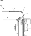
- Figure 2 - is the partial cross-sectional view of the cooking device to which the support member is mounted in an embodiment of the present invention.
- Figure 3 - is the partial cross-sectional view of the cooking device when the support member is mounted to the cooking device in an embodiment of the present invention.
- the support member (1) is suitable to be used for the assembly of a cooking device (100) comprising a cooking chamber (P) wherein the foodstuffs are cooked and a door (K) providing access into the cooking chamber (P), especially the assembly of a first coating plate (2) that surrounds the upper portion of the cooking chamber (P) and a second coating plate (3) that is situated above the door (K) and that partially covers the first coating plate (2).
- the support member (1) comprises a top wall (4) that enables the support member (1) to bear from below against the portions of the first coating plate (2) and the second coating plate (3) that seat one above the other, a base (5) that enables the support member (1) to bear from above against the inner surface of the second coating plate (3) and an interlocking portion (6) that is situated at the portion of the second coating plate (3) partially covering the first coating plate (2) and that is suitable to be interlocked with the front portion of the first coating plate (2) ( Figure 1).
- the coating plates (2, 3) are enabled to be joined in a durable manner without being screwed to each other.
- the support member (1) comprises a recess (13) that is situated at the interlocking portion (6), that is suitable to receive the front portion of the first coating plate (2) and that opens from the top wall (4) inside ( Figure 1). During the assembly, the front portion of the first coating plate (2) is placed into the recess (13).
- the width of the recess (13) is smaller than the thickness of the first coating plate (2).
- the width of the recess (13) is equal to the thickness of the first coating plate (2) or larger than the thickness of the first coating plate (2). During the assembly, the front portion of the first coating plate (2) is freely placed into the recess (13).
- the support member (1) comprises one or more than one pin (8) that is situated at the interlocking portion (6), that extends into the recess (13) in a direction perpendicular to the lateral surface of the recess (13) and that can be inserted into one or more than one hole (not shown in the figures) bored on the first coating plate (2).
- the front portion of the first coating plate (2) is placed into the recess (13) and the front portion of the first coating plate (2) is interlocked with the pin (8) that extends into the recess (13) at the interlocking portion (6).
- the support member (1) is prevented from sliding off its position.
- the support member (1) is fixed to the coating plates (2, 3) and furthermore prevented from coming loose by means of the top wall (4) and the base (5) that bear against the coating plates (2, 3).
- the support member (1) comprises an extension (7) that is situated at the interlocking portion (6) and that bears against the front portion of the first coating plate (2) ( Figure 1 and Figure 3).
- the front portion of the first coating plate (2) is interlocked with the support member (1) under a predetermined pressure by means of the extension (7).
- the support member (1) is fixed to the coating plates (2, 3) and furthermore prevented from coming loose by means of the top wall (4) and the base (5) that bear against the coating plates (2, 3).
- the extension (7) is formed as an L-shaped projecting wall that rises from the front portion of the support member (1) to the top wall (4) thereof and that has the pin (8) at its inner side that extends into the recess (13) ( Figure 1). During the assembly, the hole bored on the front portion of the first coating plate (2) is interlocked with the pin (8) situated at the inner side of the extension (7).
- the extension (7) is situated on the top wall (4) of the support member (1).
- the support member (1) is produced from hard plastic.
- the support member (1) is enabled to be resistant to pressure and also flexible.
- the support member (1) has a hollow structure and comprises one or more than one upright member (9) that extends between the top wall (4) and the base (5) ( Figure 1).
- the support member (1) is enabled to be lightweight, low-cost and durable by means of its hollow structure and the upright member (9).
- the cooking device (100) comprises the above-mentioned support member (1) ( Figure 3).
- the cooking device (100) comprises a jacket sheet metal (10) produced from the first coating plate (2), a front panel (11) produced from the second coating plate (3) and a corner (12) that is situated between the jacket sheet metal (10) and the front panel (11) and that is formed by joining the jacket sheet metal (10) and the front panel (11) without screw or welding at the region where the front panel (11) partially covers the jacket sheet metal (10) ( Figure 3)
- the length of the support member (1) is equal to or shorter than the width of the cooking device (100). Depending on the width of the support member (1), one or more than one support member (1) can be used in the assembly of the jacket sheet metal (10) and the front panel (11) of the cooking device (100).
- the length of the support member (1) is almost equal to the width of the cooking device (100).
- the cooking device (100) comprises one support member (1) that extends longitudinally between the jacket sheet metal (10) and the front panel (11) above the door (K).
- the cooking device (100) comprises more than one support member (1) that extends longitudinally and consecutively between the jacket sheet metal (10) and the front panel (11) above the door (K).
- the top wall (4) of the support member (1) bears from below against a portion of the jacket sheet metal (10) and the portion of the front panel (11) partially covering the jacket sheet metal (10) ( Figure 3).
- the base (5) of the support member (1) bears from above against the inner surface of the front panel (11) ( Figure 3).
- the interlocking portion (6) of the support member (1) is interlocked only with the front portion of the jacket sheet metal (10) that is partially covered by the front panel (11) in a manner not visible from the outside ( Figure 3).
- the assembly process can be realized without requiring screws.
- a durable, lightweight and low cost support member (1) is realized, that can be mass-produced and easily applied between the top jacket sheet metal (10) and the front panel (11) especially in cooking devices (100), for example in ovens, that does not require screws for assembly and that prevents deformations and especially depressions that may occur due to utilization.
- Utilization of the support member (1) of the present invention in household appliances other than the cooking devices (100) should also be considered within the scope of the present invention.
Landscapes
- Engineering & Computer Science (AREA)
- Chemical & Material Sciences (AREA)
- Combustion & Propulsion (AREA)
- Mechanical Engineering (AREA)
- General Engineering & Computer Science (AREA)
- Baking, Grill, Roasting (AREA)
Abstract
The present invention relates to a support member (1) suitable to be used in the assembly of the coating plates (2, 3) of a cooking device (100) and also relates to a cooking device (100) wherein the support member (1) is used.
Description
The present invention relates to a support member suitable to be used in the assembly of the coating plates of a cooking device and also relates to a cooking device wherein the support member is used.
Present cooking devices, for example midi/mini ovens, comprise a jacket sheet metal that encloses the device, including the top of the device, and a panel sheet metal that is situated at the front side of the device and above the door.
Users do not prefer white goods with visible screw connections, therefore producers do not use screw connections between the jacket sheet metal enclosing the device and the panel sheet metal enclosing the front of the device in order to provide esthetic designs. As a result of this, deformations occur in the jacket sheet metal in the course of time due to usage. Deformations occurring at the top parts of this type of products after production are in form of depressions. These deformations cause user complaints and increase the number of malfunctions reported to the related service departments.
The aim of the present invention is the realization of a durable and low cost support member that is easy to mass-produce and assemble and that enables the jacket sheet metal enclosing the cooking device and the front panel sheet metal situated at the front side of the device to be connected without using screws, and also the realization of a cooking device wherein the support member is used.
The support member realized in order to attain the aim of the present invention, explicated in the attached claims is suitable to be used in the assembly of a first coating plate forming the jacket of a cooking device and a second coating plate forming the front panel thereof, and comprises a top wall bearing from under against a portion of the first coating plate and a front portion of the second coating plate covering the first coating plate, a base bearing from above against the inner surface of the second coating plate and an interlocking portion that is suitable to interlock with the front portion of the first coating plate situated at the portion of the second coating plate covering the first coating plate. The support member enables the coating plates to be joined in a durable manner without being screwed to each other.
In an embodiment of the present invention, the support member comprises a recess that is situated at the interlocking portion, that is suitable to receive the front portion of the first coating plate and that opens from the top wall into the body thereof. During the assembly, the front portion of the first coating plate is placed into the said recess.
In another embodiment of the present invention, the width of the recess is preferably a little smaller than the thickness of the first coating plate.
In another embodiment of the present invention, the width of the recess is preferably equal to or wider than the thickness of the first coating plate.
In another embodiment of the present invention, one or more than one pin is provided on the inner surface of the recess, that is suitable to be inserted into one or more than hole bored on the front portion of the first coating plate. During the assembly, the front portion of the first coating plate is placed into the said recess and the hole bored on the front portion of the first coating plate is interlocked with the pin situated inside the recess.
In an embodiment of the present invention, the interlocking portion of the support member comprises an extension that is suitable to be interlocked with a front portion of the first coating plate in a detachable manner. During the assembly, the front portion of the first coating plate is interlocked with the said extension.
In another embodiment of the present invention, the extension on the interlocking portion is formed as an L-shaped projecting wall that rises from the front portion of the support member to the top wall thereof and that has the pin at its inner side suitable to be inserted into a hole bored on the front portion of the first coating plate.
In an embodiment of the present invention, the support member has a hollow structure, and the top wall and the base thereof are joined by at least one upright member. Thus, compression forces acting on the wall and base of the support member are transferred to the upright member.
In an embodiment of the present invention, the cooking device of the present invention comprises a top jacket sheet metal formed from a first coating plate, a front panel formed from a second coating plate different from the first coating plate, a corner that is situated between the jacket sheet metal and the front panel and that is formed by joining the top jacket sheet metal and the front panel without screw or welding at the region where the second coating plate partially covers the first coating plate, and also comprises at least one support member that is mounted between the jacket sheet metal and the front panel.
By means of the present invention, a durable, lightweight and low cost support member is realized, that can be mass-produced and easily applied between the top jacket sheet metal and the front panel, that does not require screws for assembly and that prevents deformations and especially depressions that may occur due to utilization. Moreover, by means of the present invention, an esthetic and durable cooking device is realized.
The model embodiments that relate to the support member realized in order to attain the aim of the present invention and to the cooking device where the same is used are illustrated in the attached figures, where:
Figure 1 - is the sideways view of the support member in an embodiment of the present invention.
Figure 2 - is the partial cross-sectional view of the cooking device to which the support member is mounted in an embodiment of the present invention.
Figure 3 - is the partial cross-sectional view of the cooking device when the support member is mounted to the cooking device in an embodiment of the present invention.
The elements illustrated in the figures are numbered as follows:
- Support member
- First coating plate
- Second coating plate
- Top wall
- Base
- Interlocking portion
- Extension
- Pin
- Upright member
- Jacket sheet metal
- Front panel
- Corner
- Recess
100. Cooking device
The support member (1) is suitable to be used for the assembly of a cooking device (100) comprising a cooking chamber (P) wherein the foodstuffs are cooked and a door (K) providing access into the cooking chamber (P), especially the assembly of a first coating plate (2) that surrounds the upper portion of the cooking chamber (P) and a second coating plate (3) that is situated above the door (K) and that partially covers the first coating plate (2).
The support member (1) comprises a top wall (4) that enables the support member (1) to bear from below against the portions of the first coating plate (2) and the second coating plate (3) that seat one above the other, a base (5) that enables the support member (1) to bear from above against the inner surface of the second coating plate (3) and an interlocking portion (6) that is situated at the portion of the second coating plate (3) partially covering the first coating plate (2) and that is suitable to be interlocked with the front portion of the first coating plate (2) (Figure 1). By means of the support member (1), the coating plates (2, 3) are enabled to be joined in a durable manner without being screwed to each other.
In an embodiment of the present invention, the support member (1) comprises a recess (13) that is situated at the interlocking portion (6), that is suitable to receive the front portion of the first coating plate (2) and that opens from the top wall (4) inside (Figure 1). During the assembly, the front portion of the first coating plate (2) is placed into the recess (13).
In another embodiment of the present invention, the width of the recess (13) is smaller than the thickness of the first coating plate (2). During the assembly, the front portion of the first coating plate (2) is placed into the recess (13) by applying a little pressure, thus the support member (1) is prevented from sliding.
In another embodiment of the present invention, the width of the recess (13) is equal to the thickness of the first coating plate (2) or larger than the thickness of the first coating plate (2). During the assembly, the front portion of the first coating plate (2) is freely placed into the recess (13).
In another embodiment of the present invention, the support member (1) comprises one or more than one pin (8) that is situated at the interlocking portion (6), that extends into the recess (13) in a direction perpendicular to the lateral surface of the recess (13) and that can be inserted into one or more than one hole (not shown in the figures) bored on the first coating plate (2). During the assembly, the front portion of the first coating plate (2) is placed into the recess (13) and the front portion of the first coating plate (2) is interlocked with the pin (8) that extends into the recess (13) at the interlocking portion (6). Thus, the support member (1) is prevented from sliding off its position. The support member (1) is fixed to the coating plates (2, 3) and furthermore prevented from coming loose by means of the top wall (4) and the base (5) that bear against the coating plates (2, 3).
In an embodiment of the present invention, the support member (1) comprises an extension (7) that is situated at the interlocking portion (6) and that bears against the front portion of the first coating plate (2) (Figure 1 and Figure 3). During the assembly, the front portion of the first coating plate (2) is interlocked with the support member (1) under a predetermined pressure by means of the extension (7). Thus, the support member (1) is fixed to the coating plates (2, 3) and furthermore prevented from coming loose by means of the top wall (4) and the base (5) that bear against the coating plates (2, 3).
In another embodiment of the present invention, the extension (7) is formed as an L-shaped projecting wall that rises from the front portion of the support member (1) to the top wall (4) thereof and that has the pin (8) at its inner side that extends into the recess (13) (Figure 1). During the assembly, the hole bored on the front portion of the first coating plate (2) is interlocked with the pin (8) situated at the inner side of the extension (7).
In another embodiment of the present invention, the extension (7) is situated on the top wall (4) of the support member (1).
In another embodiment of the present invention, the support member (1) is produced from hard plastic. Thus, the support member (1) is enabled to be resistant to pressure and also flexible.
In an embodiment of the present invention, the support member (1) has a hollow structure and comprises one or more than one upright member (9) that extends between the top wall (4) and the base (5) (Figure 1). Thus, the forces acting on the top wall (4) and the base (5) of the support member (1) are carried by the upright member (9). Moreover, the support member (1) is enabled to be lightweight, low-cost and durable by means of its hollow structure and the upright member (9).
In an embodiment of the present invention, the cooking device (100) comprises the above-mentioned support member (1) (Figure 3).
In another embodiment of the present invention, the cooking device (100) comprises a jacket sheet metal (10) produced from the first coating plate (2), a front panel (11) produced from the second coating plate (3) and a corner (12) that is situated between the jacket sheet metal (10) and the front panel (11) and that is formed by joining the jacket sheet metal (10) and the front panel (11) without screw or welding at the region where the front panel (11) partially covers the jacket sheet metal (10) (Figure 3)
The length of the support member (1) is equal to or shorter than the width of the cooking device (100). Depending on the width of the support member (1), one or more than one support member (1) can be used in the assembly of the jacket sheet metal (10) and the front panel (11) of the cooking device (100).
In another embodiment of the present invention, the length of the support member (1) is almost equal to the width of the cooking device (100). In this embodiment, the cooking device (100) comprises one support member (1) that extends longitudinally between the jacket sheet metal (10) and the front panel (11) above the door (K).
In another embodiment of the present invention, the cooking device (100) comprises more than one support member (1) that extends longitudinally and consecutively between the jacket sheet metal (10) and the front panel (11) above the door (K).
In the assembled state, the top wall (4) of the support member (1) bears from below against a portion of the jacket sheet metal (10) and the portion of the front panel (11) partially covering the jacket sheet metal (10) (Figure 3). In the assembled state, the base (5) of the support member (1) bears from above against the inner surface of the front panel (11) (Figure 3). In the assembled state, the interlocking portion (6) of the support member (1) is interlocked only with the front portion of the jacket sheet metal (10) that is partially covered by the front panel (11) in a manner not visible from the outside (Figure 3). Thus, the assembly process can be realized without requiring screws.
By means of the present invention, a durable, lightweight and low cost support member (1) is realized, that can be mass-produced and easily applied between the top jacket sheet metal (10) and the front panel (11) especially in cooking devices (100), for example in ovens, that does not require screws for assembly and that prevents deformations and especially depressions that may occur due to utilization. Utilization of the support member (1) of the present invention in household appliances other than the cooking devices (100) should also be considered within the scope of the present invention.
Claims (14)
- A support member (1) suitable to be used in cooking devices (100) comprising a cooking chamber (P) wherein the foodstuffs are cooked, a door (K) providing access into the cooking chamber (P), a first coating plate (2) that surrounds the upper portion of the cooking chamber (P) and a second coating plate (3) that is situated above the door (K), characterized in that- a top wall (4) that enables the support member (1) to bear from below against the portions of the first coating plate (2) and the second coating plate (3) that seat one above the other,- a base (5) that enables the support member (1) to bear from above against the inner surface of the second coating plate (3) and- an interlocking portion (6) that is situated at the portion of the second coating plate (3) partially covering the first coating plate (2) and that enables the support member (1) to be interlocked with the front portion of the first coating plate (2).
- A support member (1) as in Claim 1, characterized in that a recess (13) that is situated at the interlocking portion (6), that is suitable to receive the front portion of the first coating plate (2) and that opens from the top wall (4) inside.
- A support member (1) as in Claim 2, characterized in that the recess (13) of which the width is smaller than the thickness of the first coating plate (2).
- A support member (1) as in Claim 2, characterized in that the recess (13) of which the width is equal to or larger than the thickness of the first coating plate (2).
- A support member (1) as in any one of the above claims, characterized in that one or more than one pin (8) that is situated at the interlocking portion (6) and that can be inserted into one or more than one hole bored on the first coating plate (2).
- A support member (1) as in any one of the above claims, characterized in that one or more than one pin (8) that extends into the recess (13) in a direction perpendicular to the lateral surface of the recess (13).
- A support member (1) as in any one of the above claims, characterized in that an extension (7) that is situated at the interlocking portion (6) and that bears against the front portion of the first coating plate (2).
- A support member (1) as in Claim 7, characterized in that the extension (7) that is formed as an L-shaped projecting wall that rises from the front portion of the support member (1) to the top wall (4) thereof and that has the pin (8) at its inner side that extends into the recess (13).
- A support member (1) as in Claim 7, characterized in that the extension (7) that is situated at the top wall (4) of the support member (1).
- A support member (1) as in any one of the above claims, that is produced from plastic and has a hollow structure and characterized in that one or more than one upright member (9) that extends between the top wall (4) and the base (5).
- A cooking device (100) characterized in that a support member (1) as in any one of the above claims.
- A cooking device (100) as in Claim 11, characterized in that a jacket sheet metal (10) produced from the first coating plate (2), a front panel (11) produced from the second coating plate (3) and one or more than one support member (1) placed between the jacket sheet metal (10) and the front panel (11).
- A cooking device (100) as in Claim 12, characterized in that one support member (1) that extends longitudinally between the jacket sheet metal (10) and the front panel (11) above the door (K).
- A cooking device (100) as in Claim 12, characterized in that one or more than one support member (1) that extends longitudinally and consecutively between the jacket sheet metal (10) and the front panel (11) above the door (K).
Applications Claiming Priority (2)
| Application Number | Priority Date | Filing Date | Title |
|---|---|---|---|
| TRA2013/01237 | 2013-01-31 | ||
| TR201301237 | 2013-01-31 |
Publications (2)
| Publication Number | Publication Date |
|---|---|
| WO2014118304A2 true WO2014118304A2 (en) | 2014-08-07 |
| WO2014118304A3 WO2014118304A3 (en) | 2014-12-11 |
Family
ID=50029057
Family Applications (1)
| Application Number | Title | Priority Date | Filing Date |
|---|---|---|---|
| PCT/EP2014/051859 Ceased WO2014118304A2 (en) | 2013-01-31 | 2014-01-30 | A support member for cooking devices and the cooking device wherein the same is used |
Country Status (1)
| Country | Link |
|---|---|
| WO (1) | WO2014118304A2 (en) |
Cited By (1)
| Publication number | Priority date | Publication date | Assignee | Title |
|---|---|---|---|---|
| US10145564B2 (en) | 2014-12-24 | 2018-12-04 | Lg Electronics Inc. | Cooking appliance |
Family Cites Families (9)
| Publication number | Priority date | Publication date | Assignee | Title |
|---|---|---|---|---|
| US2675797A (en) * | 1954-04-20 | Stove construction | ||
| GB411840A (en) * | 1932-12-12 | 1934-06-12 | R & A Main Ltd | Improvements in or relating to cooking ovens |
| GB738373A (en) * | 1951-02-03 | 1955-10-12 | Cannon Ind Ltd | Improvements in or relating to cooker doors and wall panels |
| US3965540A (en) * | 1975-01-29 | 1976-06-29 | Armstrong Store Fixture Corporation | Clip for mounting a crossbar to a bracket |
| DE19613320C1 (en) * | 1996-04-03 | 1997-04-30 | Bauknecht Hausgeraete | Worksurface fixing system for domestic electrical appliance |
| DE19755594A1 (en) * | 1997-12-15 | 1999-06-17 | Volkswagen Ag | Elastic deformable clamp body |
| FR2817302B1 (en) * | 2000-11-28 | 2004-10-08 | Neyr Plastiques Holding | DEVICE FOR FASTENING AN ACCESSORY ON A VEHICLE |
| EP2444168A3 (en) * | 2004-10-07 | 2014-06-25 | Elro (Holding ) AG | High pressure cleaner resistant sealing elements for cooking devices and cover for a cooking device |
| PL2532975T3 (en) * | 2011-06-07 | 2014-09-30 | Fagor S Coop | Cooking appliance adapted for low pressure cooking |
-
2014
- 2014-01-30 WO PCT/EP2014/051859 patent/WO2014118304A2/en not_active Ceased
Non-Patent Citations (1)
| Title |
|---|
| None |
Cited By (2)
| Publication number | Priority date | Publication date | Assignee | Title |
|---|---|---|---|---|
| US10145564B2 (en) | 2014-12-24 | 2018-12-04 | Lg Electronics Inc. | Cooking appliance |
| EP3037732B1 (en) * | 2014-12-24 | 2019-01-09 | LG Electronics Inc. | Cooking appliance |
Also Published As
| Publication number | Publication date |
|---|---|
| WO2014118304A3 (en) | 2014-12-11 |
Similar Documents
| Publication | Publication Date | Title |
|---|---|---|
| US9303916B2 (en) | Built-in household appliance comprising a decorative panel | |
| USD773622S1 (en) | Campfire stove and fire pit | |
| KR101717531B1 (en) | cooking appliance | |
| USD657191S1 (en) | Appliance with a front having the appearance of chamfered sides with rounded edges | |
| US20180142941A1 (en) | Home Appliance Door | |
| ITPR20130094A1 (en) | FREE INSTALLATION KITCHEN. | |
| WO2009141126A3 (en) | Cold appliance | |
| US20120048258A1 (en) | Adjustable grate foot for home appliance | |
| EP2798136B1 (en) | A household appliance | |
| WO2017133782A1 (en) | Hinge assembly for use in a laundry treatment appliance | |
| WO2011147898A3 (en) | Household appliance with gap between a compartment of the appliance and storage unit received within the compartment and a gap shielding member | |
| WO2010020540A3 (en) | Door for a household appliance | |
| WO2012072453A3 (en) | Household appliance including glass interior walls | |
| US11835237B2 (en) | Oven appliance and door assembly | |
| KR200465969Y1 (en) | Commercial cooker | |
| WO2015062665A1 (en) | Refrigerator door and method of manufacturing the same | |
| AU2017422539B2 (en) | Household appliance | |
| WO2015189773A1 (en) | Household appliance | |
| US20090096333A1 (en) | Furniture Arrangement for Built-in Appliances | |
| US20130192584A1 (en) | Heating element mounting features for a cook top appliance | |
| CN211290706U (en) | Household appliance door | |
| JP2007229022A (en) | Partition counter | |
| WO2014041334A3 (en) | An improved barbecue | |
| ATE549958T1 (en) | BUILT-IN PARTS SET FOR A BUILT-IN HOUSEHOLD APPLIANCE | |
| US9803730B1 (en) | Home appliance device |
Legal Events
| Date | Code | Title | Description |
|---|---|---|---|
| 122 | Ep: pct application non-entry in european phase |
Ref document number: 14701786 Country of ref document: EP Kind code of ref document: A2 |